the unrestrainable growth of a shear band in a prestressed
TRANSCRIPT

on December 5, 2018http://rspa.royalsocietypublishing.org/Downloaded from
The unrestrainable growth of a shear bandin a prestressed material
BY D. BIGONI* AND F. DAL CORSO
Department of Mechanical and Structural Engineering, University of Trento,via Mesiano 77, 38050 Trento, Italy
A weak line inclusion model in a nonlinear elastic solid is proposed to analyticallyquantify and investigate, for the first time, the stress state and growth conditions of afinite-length shear band in a ductile prestressed metallic material. The deformation isshown to become highly focused and aligned coaxial to the shear band—a finding thatprovides justification for the experimentally observed strong tendency towards rectilinearpropagation—and the energy release rate to blow up to infinity, for incremental loadingoccurring when the prestress approaches the elliptic boundary. It is concluded that thepropagation becomes ‘unrestrainable’, a result substantiating the experimentalobservation that shear bands are the preferential near-failure deformation modes.
Keywords: failure of ductile materials; strain localization; energy release rate;slip surface growth
Elehtt
*A
1FeFortopThe2Thdire(Giver
RecAcc
1. Introduction
Localized deformations in the form of shear bands emerging from a slowly varyingdeformation field are known to be the preferential near-failure deformationmodes of ductile materials (e.g. Fenistein & van Hecke 2003; Bei et al. 2006;Lewandowski & Greer 2006; Rittel et al. 2006). Therefore, shear band formation isthe key concept to explain failure in many materials and, according to itstheoretical and ‘practical’ importance, it has been the focus of an enormousresearch effort in the last 30 years. From the theoretical point of view, this efforthas been mainly directed in two ways,1 namely the dissection of the specificconstitutive features responsible for strain localization in different materials2 and
Proc. R. Soc. A (2008) 464, 2365–2390
doi:10.1098/rspa.2008.0029
Published online 25 April 2008
ctronic supplementary material is available at http://dx.doi.org/10.1098/rspa.2008.0029 or viap://journals.royalsociety.org.
uthor for correspondence ([email protected]).
atures of strain localization occurring after its onset have scarcely been theoretically explored.instance, there is almost nothing about post-localization behaviour. Research devoted to thisic has been developed by Hutchinson & Tvergaard (1981), Tvergaard (1982), Petryk &rmann (2002) and Gajo et al. (2004).is line of research has been initiated by Rudnicki & Rice (1975) and developed in a number ofctions (including gradient effects (Aifantis 1987; Aifantis & Willis 2005), temperature effectsoia & Ortiz 1996; Benallal & Bigoni 2004), anisotropy effects (Bigoni & Loret 1999) and yield-tex effects (Petryk & Thermann 2002)).
eived 24 January 2008epted 12 March 2008 2365 This journal is q 2008 The Royal Society

D. Bigoni and F. Dal Corso2366
on December 5, 2018http://rspa.royalsocietypublishing.org/Downloaded from
the struggle for the overcoming of difficulties connected with numericalapproaches.3 Although these problems still seem far from being definitely solved,the most important questions in this research area have only marginally beenapproached and are therefore still awaiting explanation. They are as follows.
(i) The highly inhomogeneous stress/deformation state developing near ashear band tip is unknown from an analytical point of view (and numericaltechniques can hardly have the appropriate resolution to detail this).
(ii) It is not known if a shear band tip involves a strong stress concentration.(iii) The fact that shear bands grow quasi-statically and rectilinearly for
remarkably long distances under mode II loading conditions, while the samefeature is not observed in the akin problem of crack growth, remainsunexplained.
(iv) Finally, and most importantly, the reason why shear bands are preferentialfailure modes for quasi-statically deformed ductile materials has nojustification.
Surprisingly, analytical investigation of the above problems and even of thestress field generated by a finite-length shear band, possibly including near-tipsingularities, has never been attempted. Moreover, shear band growth has beenconsidered only in a context pertaining to slope-stability problems in soilmechanics (Palmer & Rice 1973; Rice 1973), an approach recently developed byPuzrin & Germanovich (2005).
A full-field solution is given here for a finite-length shear band4 in ananisotropic, prestressed, nonlinear elastic material, incrementally loaded undermode II and revealing: stress singularity; high inhomogeneity of the deformationand its focusing parallel and coaxially aligned to the shear band. Moreover, theincremental energy release rate is shown to blow up when the stress stateapproaches the condition for strain localization (i.e. the elliptic boundary). Thesegeneral findings are applied to the so-called ‘J2-deformation theory material’,
the most important constitutive model for the plastic response of ductile metals,5
and provide justification to the above-mentioned aspects of shear banding inductile materials.
3 Reviews on the numerical work developed in these years have been given by Needleman &Tvergaard (1983) and Petryk (1997).4 In addition to the shear band solution, we provide in appendix B the full-field solution for a finite-length crack in a prestressed material loaded incrementally under modes I and II. This solution isnew in the case when the crack is inclined with respect to the material’s orthotropic axes and isfundamental to the understanding of the shear band problem. Although based on the assumptionthat dead loading tractions are present inside the crack to equilibrate the assumed prestress state,this solution is interesting in itself, when used near the boundary of ellipticity loss, since it revealsfeatures related to the interaction between shear bands and crack tip fields, so that it may explainexperimental observations relative to crack growth in ductile materials (McClintock 1971;Hallback & Nilsson 1994).5 The finite-strain J2-deformation theory of plasticity has been proposed by Hutchinson & Neale(1979). This theory accounts for the most important features of plastic flow in metals (except forthe possibility of elastic unloading, which is a priori ruled out) and correctly predicts the onset ofshear banding (see Hutchinson & Tvergaard 1981).
Proc. R. Soc. A (2008)

(a) (b)
Figure 1. Sketch of (b) a weak interface to model (a) a shear band (inspired by a deformationband observed in dry sandstone by Sulem & Ouffroukh (2006)). The hinged quadrilateralshould be thought to have zero thickness, so that materials in contact can freely slideincrementally along a weak surface, across which normal incremental displacement remainscontinuous. Scale bar, 1 mm.
2367Unrestrainable growth of a shear band
on December 5, 2018http://rspa.royalsocietypublishing.org/Downloaded from
2. The shear band model
A shear band of finite length, formed inside a material at a certain stage ofcontinued deformation, is a very thin layer of material across which the normalcomponent of incremental displacement and of nominal traction remaincontinuous, but the incremental nominal tangential traction vanishes, whilethe corresponding displacement becomes unprescribed (figure 1). Therefore, itresults spontaneous to model such a shear band as a weak surface along whichneighbouring materials can freely slide, but are constrained to remain in contact.Note that this slip surface is different from a crack since it can carry normaltractions, so that only under special symmetry conditions on the prestress state itmay behave as a crack when subjected to shear parallel to it (the so-called ‘modeII’ loading in fracture mechanics).
Models of slip bands similar to the weak line model have been proposed inmetal plasticity (e.g. Cottrell 1953, §10) and geomechanics (Palmer & Rice 1973;Rice 1973; Puzrin & Germanovich 2005), although the neighbouring materialsassumed in these models are free of prestress and linear elastic so that there isno correlation between the shear band and the surrounding stress that hasgenerated it.
The key to the analysis of the stress/deformation fields near a shear band andits advance under load increments is a perturbative approach similar to thatproposed by Bigoni & Capuani (2002, 2005) and Piccolroaz et al. (2006). Inparticular, an infinite, incompressible, nonlinear elastic material is considered,homogeneously deformed under the plane strain condition. According to the Biot(1965) theory, the response to an incremental loading is expressed in terms of thenominal (unsymmetrical) stress increment _t , related to the gradient of incrementaldisplacement Vv (satisfying the incompressibility constraint tr VvZ0) through thelinear relation
_t ZK½VvT�C _pI ; ð2:1Þwhere T denotes the transpose; _p is the incremental in-plane mean stress; andthe fourth-order tensor K is a function of the current state of stress (expressedthrough the principal components of Cauchy stress, s1 and s2) and material
Proc. R. Soc. A (2008)
P
0.5 1.0
0.5
1.0
(a) (b)
(c)
0k
H
EI
EC
path forJ2-materialat N = 0.3
Hill criterion
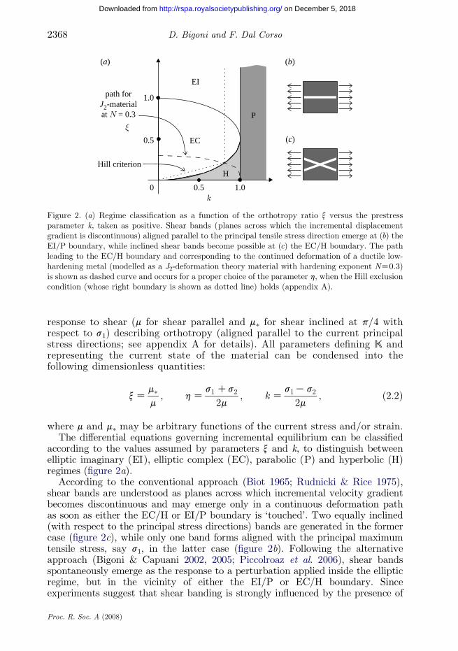
Figure 2. (a) Regime classification as a function of the orthotropy ratio x versus the prestressparameter k, taken as positive. Shear bands (planes across which the incremental displacementgradient is discontinuous) aligned parallel to the principal tensile stress direction emerge at (b) theEI/P boundary, while inclined shear bands become possible at (c) the EC/H boundary. The pathleading to the EC/H boundary and corresponding to the continued deformation of a ductile low-hardening metal (modelled as a J2-deformation theory material with hardening exponent NZ0.3)is shown as dashed curve and occurs for a proper choice of the parameter h, when the Hill exclusioncondition (whose right boundary is shown as dotted line) holds (appendix A).
D. Bigoni and F. Dal Corso2368
on December 5, 2018http://rspa.royalsocietypublishing.org/Downloaded from
response to shear (m for shear parallel and m� for shear inclined at p/4 withrespect to s1) describing orthotropy (aligned parallel to the current principalstress directions; see appendix A for details). All parameters defining K andrepresenting the current state of the material can be condensed into thefollowing dimensionless quantities:
xZm�m; hZ
s1 Cs2
2m; k Z
s1K s2
2m; ð2:2Þ
where m and m� may be arbitrary functions of the current stress and/or strain.The differential equations governing incremental equilibrium can be classified
according to the values assumed by parameters x and k, to distinguish betweenelliptic imaginary (EI), elliptic complex (EC), parabolic (P) and hyperbolic (H)regimes (figure 2a).
According to the conventional approach (Biot 1965; Rudnicki & Rice 1975),shear bands are understood as planes across which incremental velocity gradientbecomes discontinuous and may emerge only in a continuous deformation pathas soon as either the EC/H or EI/P boundary is ‘touched’. Two equally inclined(with respect to the principal stress directions) bands are generated in the formercase (figure 2c), while only one band forms aligned with the principal maximumtensile stress, say s1, in the latter case (figure 2b). Following the alternativeapproach (Bigoni & Capuani 2002, 2005; Piccolroaz et al. 2006), shear bandsspontaneously emerge as the response to a perturbation applied inside the ellipticregime, but in the vicinity of either the EI/P or EC/H boundary. Sinceexperiments suggest that shear banding is strongly influenced by the presence of
Proc. R. Soc. A (2008)

x1
x1
x2x
2
0
Figure 3. Finite-length (2l ) shear band in a prestressed orthotropic material inclined at an angle w0
(positive when anticlockwise) with respect to the orthotropy axes x1 and x2. The prestress stateis expressed through the two in-plane principal Cauchy stresses s1 and s2, aligned parallel to thex1–x2 reference system. The null shear stiffness at the band boundaries has to be understood in anincremental sense.
2369Unrestrainable growth of a shear band
on December 5, 2018http://rspa.royalsocietypublishing.org/Downloaded from
randomly distributed defects (Xue & Gray 2006), it is assumed that duringhomogeneous deformation of an infinite medium subjected to remote stress withkO0, a defect is present in the form of a thin zone of material that has touchedthe EI/P or EC/H boundary and has been transformed into a shear band oflength 2l (in other words, the weak line inclusion in the proposed modelling),leaving the surrounding material uniformly deformed/stressed and still in theelliptic regime, although near the elliptic boundary. (This uniform state ofstress has to satisfy the Hill exclusion condition, to avoid ‘spurious’ interfacialinstabilities; see appendix A.) The shear band of length 2l is inclined withrespect to the x1-axis at an angle w0 that can be determined from a knownformula (Hutchinson & Tvergaard 1981), thus providing the inclination of theweak line inclusion with respect to the material orthotropy x1-axis (figure 3).Taking this configuration as the initial state, the response of the shear band toan incremental perturbation is analysed.
According to the weak line model, under an incremental mode I perturbationthe shear band does not alter the incremental response of the surrounding material(so that it is ‘neutral’), but under a mode II perturbation the shear band behavesas a slip surface of length 2l (prestressed both longitudinally and transversely), andstrongly non-uniform and singular fields are generated.
3. Analytical solution for a shear band of finitelength loaded incrementally
The analytical solution for a finite-length crack incrementally loaded by a uniformmode II far field in a prestressed material similar to that described by equation(2.1) was available only when the crack is aligned parallel or orthogonal to theorthotropy axes, a situation corresponding to a shear band forming at the EI/Pboundary, where symmetry implies that a crack behaves as a slip surface, so thatthe crack and the weak line become equivalent models. The solution for an inclinedcrack in a prestressed material (obtained in appendix B) is interesting in itself(since it shows features of interactions between shear bands and crack tip fields)and of fundamental importance for the understanding of the shear band problemaddressed here.
Proc. R. Soc. A (2008)

D. Bigoni and F. Dal Corso2370
on December 5, 2018http://rspa.royalsocietypublishing.org/Downloaded from
For shear bands occurring at the EC/H boundary, the solution for a weak lineinclusion inclined with respect to the orthotropy axes, not previously availablefor the material under consideration, is given here. Developing this solutionfor constitutive equations (2.1) and employing it to analyse a shear band, a 1=
ffiffiffir
p
singularity is found. Moreover, a full-field representation is obtained for theincremental stress/strain field near a shear band of finite length.
The solution for an inclined shear band in an infinite medium can be expressedin a x1–x2 reference system located at the shear band centre, with the x1-axisaligned parallel to the shear band, and rotated at an angle w0 with respect tothe reference system in which constitutive equations (2.1) are expressed (figure 3).
The stress components in the x1–x2 reference system can be obtained through arotation of the components in the prestress principal reference system x1–x2, sothat, since the two systems are rotated at an angle w0 (taken positive whenanticlockwise), we have
x ZQTx; ½Q�Zcos w0 sin w0
Ksin w0 cos w0
" #; ð3:1Þ
so that the nominal stress increment, incremental displacement and its gradientcan be expressed in the x1–x2 reference system as
t ZQT _tQ; v ZQTv; Vv ZQTVvQ; ð3:2Þ
while the constitutive equations (2.1) transform to
t Z K½VvT�C _pI ; ð3:3Þ
where the transformed fourth-order tensor K is given by
Kijhk ZQliQmjKlmnoQnhQok ; ð3:4Þ
where the indices range between 1 and 2.In the x1–x2 reference system, the so-called ‘perturbed problem’ is solved in
which the traction at infinity tN21 is applied with reversed sign along the shear band
surfaces. In terms of perturbed stream function j8, defined to provide theincremental displacements as
v18Zvj8
vx2; v 28ZK
vj8
vx1; ð3:5Þ
the full-field solution for a shear band of length 2l can be written as
j8ðx1; x2ÞZtN21
2m
X2jZ1
Re BIIj f ðz jÞ
� �; ð3:6Þ
where
f ðz jÞZ z2j Kzj
ffiffiffiffiffiffiffiffiffiffiffiffiffiz2j Kl 2
qC l 2 ln z j C
ffiffiffiffiffiffiffiffiffiffiffiffiffiz2j Kl 2
q� �ð3:7Þ
Proc. R. Soc. A (2008)

2371Unrestrainable growth of a shear band
on December 5, 2018http://rspa.royalsocietypublishing.org/Downloaded from
and (Uj is purely imaginary in EI and complex in EC and Re denotes the real partof its argument)
z j Z x1 CWjx2; Wj Zsin w0 CUj cos w0
cos w0KUj sin w0
;
U2j Z
1K2xCðK1ÞjL1Kk
; LZffiffiffiffiffiffiffiffiffiffiffiffiffiffiffiffiffiffiffiffiffiffiffiffiffiffiffi4x2K4xCk2
p:
9>>>>=>>>>;
ð3:8Þ
The unknown complex constants BIIj ( jZ1, 2) in equation (3.6) can be determined
by imposing boundary conditions at the shear band surfaces, namely
—null incremental nominal shearing tractions
t 21ðx1; 0GÞZ 0; c jx1j! l; ð3:9Þ
—continuity of the incremental nominal normal traction
Et 22ðx1; 0ÞFZ 0; c jx1j! l; ð3:10Þ
—continuity of normal incremental displacement
Ev2ðx1; 0ÞFZ 0; c jx1j! l; ð3:11Þ
where the brackets E$F denote the jump of the relevant argument across theshear band.
Employing equation (3.6) and imposing the boundary conditions (3.9)–(3.11)at the sliding surface yields the following algebraic system for the unknown
constants BIIj :
Kc21 c11 Kc22 c12
c31 c41 c32 c42
Kc41 c31 Kc42 c32
0 1 0 1
26664
37775
Re ½BII1 �
Im ½BII1 �
Re ½BII2 �
Im ½BII2 �
2666664
3777775Z
0
K1
0
0
266664
377775; ð3:12Þ
where coefficients cij are defined by equations (B 6). The determinant of thecoefficient matrix in equation (3.12) vanishes both when the surface bifurcationcondition, equation (A 18), is met and at the EC/H boundary.
Similar to the crack solution, the asymptotic fields near the shear band tip resultto be given in polar coordinates (centred at the shear band tip ðx1Z l; x2Z0Þ) by
t 22ðr; 0ÞZKY _K IIffiffiffiffiffiffiffiffi2pr
p ; t 21ðr ; 0ÞZ_K IIffiffiffiffiffiffiffiffi2pr
p ; ð3:13Þ
for the incremental nominal stress ahead of the tip, where
YZt 228
tN21
Z c11 Re ½BII1 �Cc12 Im ½BII
1 �Cc13 Re ½BII2 �Cc14 Im ½BII
2 �; ð3:14Þ
Proc. R. Soc. A (2008)

D. Bigoni and F. Dal Corso2372
on December 5, 2018http://rspa.royalsocietypublishing.org/Downloaded from
while for the incremental displacements we have (where constants have beenneglected)
v1ðDlKr ; GpÞZGtN21
ffiffiffiffi2l
p ffiffiffiffiffiffiffiffiffiffiffiffiffiDlKr
p
2mIm W1B
II1 CW2B
II2
� �;
v2ðDlKr ; GpÞZHtN21
ffiffiffiffi2l
p ffiffiffiffiffiffiffiffiffiffiffiffiffiDlKr
p
2mIm BII
1 CBII2
� �;
9>>>>=>>>>;
ð3:15Þ
holding at the shear band surfaces, for ‘small’ Dl.6
In the particular case of a shear band aligned parallel to the prestress principaldirection s1 (i.e. w0Z0), solution (3.6) simplifies to
j8ZKtN21
2mRe
" P2jZ1
ðK1Þjð2xKhKðK1ÞjLÞffiffiffiffiffiffiffiffiffiffiffiffiffiffiffiffiffiffiffiffiffiffiffiffiffiffiffiffiffiffiffiffiffiffi2xK1CðK1ÞjL
qf ðz jÞ
ð2xKhCLÞ2ffiffiffiffiffiffiffiffiffiffiffiffiffiffiffiffiffiffiffiffiffiffi2xK1KL
pKð2xKhKLÞ2
ffiffiffiffiffiffiffiffiffiffiffiffiffiffiffiffiffiffiffiffiffiffiffi2xK1CL
p
#: ð3:16Þ
4. Rectilinear shear band growth is a preferred failure mode
Solution (3.6) is employed to obtain results shown in figure 4, where level sets ofincremental deviatoric strain are reported for a shear band (inclined at 29.38) in aductile low-hardening metal, modelled through the J2-deformation theory withNZ0.3, at null prestrain 3Z0 (figure 4a) and at a prestrain 3Z0.548 (figure 4b),taken close to the EC/H boundary. It can be noted from the figure (additionalresults are reported in appendix C) that, while at null prestrain (far from theelliptic boundary in figure 4a) the incremental strain field is not particularlydeveloped and does not evidence focusing, near the elliptic boundary (figure 4b) theincremental strain field is localized and elongated, and evidences a strong focusingin the direction aligned parallel to the shear band. This finding suggests that, whilemode II rectilinear crack propagation in a homogeneous material does not usuallyoccur (since in first approximation cracks deviate from rectilinearity following themaximum near-tip hoop stress inclination), shear band growth is very likely tooccur aligned with the shear band itself. This observation explains the strongtendency that shear bands evidence towards the rectilinear propagation for long(compared with their thickness) distances (e.g. Korbel & Bochniak 2004; Bei et al.2006). Moreover, the focusing of incremental deformation and the stresssingularity strongly promotes shear band growth.
6 The following properties of function Y
Yðk Z 0;w0ÞZYðk;w0 Z 0ÞZYðk;w0 Zp=2ÞZ 0
have been proven, while the properties
YZYðk;w0ÞZKYðKk;p=2Kw0Þ
have been numerically found to hold, from which the identities
Yðk;w0 Zp=4ÞZ 1Kffiffiffiffiffiffiffiffiffiffiffiffi1Kk2
p
kand Yðk;w0 Zp=3ÞZ
ffiffiffi3
pð2CkK2
ffiffiffiffiffiffiffiffiffiffiffiffi1Kk2
pÞ
4C5k
follow with the help of a symbolic manipulator.
Proc. R. Soc. A (2008)

0 = 29.3°
(a) (b)
Figure 4. Level sets of the modulus of incremental deviatoric strain, near a shear band of length 2l(demonstrated by a thin rectangle, providing the scale bar of the representation) in a low-hardening ductile metal (a J2-deformation theory material with NZ0.3). (a) Null prestrain, 3Z0,and (b) uniform prestrain near the EH/C boundary, 3Z0.548, are considered for mode IIincremental loading parallel to the shear band (inclined at w0Z29.38 with respect to the principalCauchy stress direction s1). Parameter h has been taken as equal to 0.52k, so that the Hillexclusion condition holds.
2373Unrestrainable growth of a shear band
on December 5, 2018http://rspa.royalsocietypublishing.org/Downloaded from
To further analyse shear band growth, the incremental energy release rate for aninfinitesimal shear band advance (see appendix Bc) can be calculated for anorthotropic prestressed material, equation (2.1), by employing the asymptotic
near-tip representations (3.13) and (3.15) in equation (B 19)7
_GsbZ _K
2II
Im W1BII1 CW2B
II2
� �4m
; ð4:1Þ
where the complex constants BIIj are the solutions of equation (3.12). Equation
(4.1) becomes, for a shear band aligned parallel to the principal direction ofprestress s1 (w0Z0),
_GsbZ
_K2II
m
Lffiffiffiffiffiffiffiffiffiffiffi1Ck
p
ð2xKhCLÞ2ffiffiffiffiffiffiffiffiffiffiffiffiffiffiffiffiffiffiffiffiffiffi2xK1KL
pKð2xKhKLÞ2
ffiffiffiffiffiffiffiffiffiffiffiffiffiffiffiffiffiffiffiffiffiffiffi2xK1CL
p : ð4:2Þ
7Note that the perturbed solution for the shear band model can be alternatively obtained providinga mixed-mode loading to an inclined crack (see appendix Ba). The mode I loading component is‘calibrated’ with respect to the mode II component in such a way as to eliminate the jump innormal incremental displacement along the crack faces generated by a pure mode II loading, inother words, to satisfy condition (3.11). All these procedures bear on the special feature foundin the solution of the crack problem that a mode I uniform loading along the crack faces is sufficientto eliminate a mode II transversal mismatch in incremental displacements. In particular equation(4.1) can be obtained from equation (B 23), considering a mixed mode defined by t
N22ZKYt
N21, so
that the condition of continuity of transversal incremental displacement yields
Im ½AII1 CAII
2 �KY Im ½AI1 CAI
2�Z 0;
and the constants defining the crack and shear band solutions are related through
BIIj ZAII
j KYAIj ; j Z 1; 2:
Therefore, the difference between the crack and shear band problems lies in a uniform nominalnormal stress increment applied at the crack surfaces.
Proc. R. Soc. A (2008)

0.577
0.60.40.20
5
10
15
1.826G
Figure 5. Incremental energy release rate _Gsb
(made dimensionless by multiplying by 4m= _K2II) for
an infinitesimal growth of a shear band (inclined at w0Z29.38) in a low-hardening ductile metal (aJ2-deformation theory material with NZ0.3 and hZ0.52k), as a function of the prestrainparameter 3, equal to 0.577 at the EC/H boundary, so that shear band growth becomes‘unrestrainable’ when this boundary is approached.
D. Bigoni and F. Dal Corso2374
on December 5, 2018http://rspa.royalsocietypublishing.org/Downloaded from
In equations (4.1) and (4.2) constant _K II is the incremental mode II stress intensityfactor, defining the intensity of the singularity in terms of applied incrementalloading t
N21 and equal to
_K II Z tN21
ffiffiffiffiffipl
p; ð4:3Þ
for a rectilinear shear band of length 2l in an infinite material (inclined withrespect to the orthotropy and prestress axes).
The release rate (4.1) represents the energy released for an infinitesimal advanceof the shear band and has the typical behaviour shown in figure 5, referred to thesame material considered in figure 4 (there are no qualitative changes when othervalues of the hardening exponent N are considered, see appendix C).
It is assumed in fracture mechanics that a crack advances under small-scaleyielding when the energy release rate exceeds a critical threshold, believed to be acharacteristic of the material. Whether this criterion can be generalized to thepresent context or not can still be a matter of discussion, but the important pointis that the incremental energy release rate blows up to infinity when the ellipticboundary is approached. In these conditions, a shear band can drive itself on andovercome possible barriers; in other words, it can grow ‘unrestrainable’, a findingwhich, together with the previous results on near-tip stress/deformation states,legitimizes for the first time the common experimental observation that shearbands are the preferred near-failure deformation modes.
5. Conclusions
The modelling of a finite-length shear band in an infinite prestressed materialpresented in this article keeps into account stress-induced and inherent anisotropy,and large strain effects. Quasi-statically loaded ductile materials have beenaddressed exhibiting incompressible flow, typically metals, and the modellingpermits the first explicit closed-form evaluation of all mechanical fields near a shearband of finite length and provides justification to the fact that shear bands arepreferred modes growing rectilinearly for long distances, as experimentally found by
Proc. R. Soc. A (2008)
2375Unrestrainable growth of a shear band
on December 5, 2018http://rspa.royalsocietypublishing.org/Downloaded from
Korbel & Bochniak (2004) among others. A number of features in the modelling ofthe material (the possibility of elastic unloading outside the shear band, dynamicloading and thermal effects and, for granular materials and soils, pressure sensitivityof yielding and plastic flow dilatancy) and of the shear band (the possibility ofintroducing cohesive tangential forces between the weak line surfaces) have beensacrificed for mathematical tractability, although their incorporation can certainlybe pursued. In particular, elastic unloading near the shear band and thermal effectshave been found to be important (the latter when dynamic loading is involved,Guduru et al. (2001), while the former even for quasi-static loading, Gajo et al.(2004)) and the development of weak cohesive forces at the shear band surfacesmight prelude the extreme loss of (incremental) stiffness assumed in our model.However, considering our previous treatment of various perturbations in materialsprestressed near the boundary of ellipticity loss (Bigoni & Capuani 2002, 2005;Piccolroaz et al. 2006), we believe that the results presented in this article havegeneral validity and can be extended to include much more complicated effects.
Financial support of Trento University is gratefully acknowledged.
Appendix A. Incremental constitutive equations for incompressiblenonlinear elasticity
According to the Biot (1965) theory, the response of a nonlinear elastic,incompressible and uniformly deformedmaterial subjected to an incremental loadingis expressed in terms of the nominal (unsymmetrical) stress increment _t , related tothe gradient of incremental displacement Vv (satisfying the incompressibilityconstraint tr VvZ0) through the linear relation (2.1) where the components ofconstitutive fourth-order tensor K (possessing the major symmetry KijhkZKhkij) are
K1111 ZmðxKkKhÞ; K1122 ZKmx; K1112 ZK1121 Z 0;
K2211 ZKmx; K2222 ZmðxCkKhÞ; K2212 ZK2221 Z 0;
K1212 Zmð1CkÞ; K1221 ZK2112 Zmð1KhÞ; K2121 Zmð1KkÞ:
9>=>; ðA 1Þ
The components of the constitutive fourth-order tensor K depend on the currentstate of stress (expressed through the principal components of Cauchy stress, s1and s2) and material response to shear (m for shear parallel and m� for shearinclined at p/4 with respect to s1) describing orthotropy (aligned parallel to thecurrent principal stress directions), see Bigoni & Capuani (2002, 2005) for details,through the dimensionless quantities (2.2).
(a ) Positive definiteness of K
The Hill exclusion condition for bifurcation (Hill 1958) is the condition ofpositive definiteness of the constitutive fourth-order tensor K (Hill & Hutchinson1975, eqn (3.9)). Assuming mO0, in terms of dimensionless constants (2.2), thiscondition becomes
0!h!2x;k2 Ch2
2h!1; ðA 2Þ
defining a region in the space x, k and h, which bound has been reported in figure 2for h/kZ0.52, see also the electronic supplementary material.
Proc. R. Soc. A (2008)

D. Bigoni and F. Dal Corso2376
on December 5, 2018http://rspa.royalsocietypublishing.org/Downloaded from
(b ) Regime classification
Since the material response described by equations (2.1) and (2.2) isincompressible, we can introduce a stream function j(x1, x2), with the property(where a comma means differentiation with respect to the corresponding spatialvariable)
v1 Zj;2; v2 ZKj;1; ðA 3Þso that the incompressibility constraint is automatically satisfied. Assuming zerobody forces, the elimination of _p in the incremental equilibrium equations ( _tij;iZ0)gives the fourth-order partial differential equation
ð1CkÞj;1111 C2ð2xK1Þj;1122Cð1KkÞj;2222 Z 0; ðA 4Þ
derived by Biot (1965, p. 193, eqn (3.7), see also Hill & Hutchinson 1975, eqn (3.3)).Following Lekhnitskii (1981), Guz (1999), Radi et al. (2002), Cristescu et al.
(2004) and Dal Corso et al. (2008), a solution of (A 4) can be represented in termsof the analytic function F
jðx 1; x 2ÞZFðx1 CUx2Þ; ðA 5Þwhere U is a complex constant satisfying the biquadratic equation obtainedinserting representation (A 5) in equation (A 4),
1CkC2ð2xK1ÞU2 Cð1KkÞU4 Z 0: ðA 6ÞThe four roots Uj ( jZ1,., 4) of equation (A 6) satisfy equation (3.8)3 and are
real or complex depending on the values of x and k. In compact form, we write
Uj Zaj C ibj ; j Z 1;.; 4; ðA 7Þ
and define the four complex variables
zj Z x1 CUjx 2 Z x1 Cajx2 C ibjx 2; j Z 1;.; 4; ðA 8Þ
where iZffiffiffiffiffiffiffiK1
pis the imaginary unit, ajZRe [Uj] and bjZIm [Uj].
Employing equations (A 5) and (A 8), the general solution of the differentialequation (A 4) can be written as
jðx1; x2ÞZX4jZ1
FjðzjÞ: ðA 9Þ
The roots Uj, defined by equation (3.8)3 change their nature according to thevalues of parameters x and k, so that the differential equation (A 4) can beclassified as reported by Dal Corso et al. (2008). The regime classification in thek–x plane has been given by Radi et al. (2002) and is sketched in figure 2.
In the EI regime, defined as
k2!1 and 2xO1Cffiffiffiffiffiffiffiffiffiffiffiffi1Kk2
p; ðA 10Þ
we have four imaginary conjugate roots Uj, so that
a1 Za2 Z 0;b1
b2
)Z
ffiffiffiffiffiffiffiffiffiffiffiffiffiffiffiffiffiffiffiffiffiffiffiffiffiffiffiffiffiffiffiffiffiffiffiffiffiffiffiffiffiffiffiffiffiffiffiffiffiffi2xK1G
ffiffiffiffiffiffiffiffiffiffiffiffiffiffiffiffiffiffiffiffiffiffiffiffiffiffiffi4x2K4xCk2
p1Kk
sO0; ðA 11Þ
Proc. R. Soc. A (2008)

2377Unrestrainable growth of a shear band
on December 5, 2018http://rspa.royalsocietypublishing.org/Downloaded from
while in the EC regime, defined as
k2!1 and 1Kffiffiffiffiffiffiffiffiffiffiffiffi1Kk2
p!2x!1C
ffiffiffiffiffiffiffiffiffiffiffiffi1Kk2
p; ðA 12Þ
we have four complex conjugate roots Uj, so that
bZ b1 Zb2
aZKa1 Za2
�Z
ffiffiffiffiffiffiffiffiffiffiffiffiffiffiffiffiffiffiffiffiffiffiffiffiffiffiffiffiffiffiffiffiffiffiffiffiffiffiffiffiffiffiffiffiffiffiffiffiffiffi1Kk2
pGð2xK1Þ
2ð1KkÞ
sO0: ðA 13Þ
(c ) Specific cases of material behaviour
The assumption of a specific material model determines the relation between xand k. For instance, a Mooney–Rivlin material coincides with a neo-Hookeanmaterial for plane isochoric deformations, so that parameters k and x become(where l is the logarithmic stretch, representing a prestrain measure)
k Zl2KlK2
l2 ClK2; xZ 1; ðA 14Þ
while for a J2-deformation theory material (Hutchinson & Neale 1979),particularly suited to analyse the plastic branch of the constitutive response ofductile metals, we have
k Zl4K1
l4 C1; xZ
Nðl4K1Þ2ðln lÞðl4 C1Þ
; ðA 15Þ
where N is the hardening exponent. The curve in the x versus k plane described byequation (A 15) for NZ0.3 is reported in figure 2.
(d ) Shear bands inclination
At the EC/H boundary, two shear bands become simultaneously possible, theirinclinations are given by the angles Gw0 between the shear band and the x1-axisand solutions of (Hill & Hutchinson 1975)
cot2 w0 Z1C2 signðkÞ
ffiffiffiffiffiffiffiffiffiffiffiffiffiffiffiffixð1KxÞ
p1K2x
: ðA 16Þ
At the EI/P boundary, we have only one shear band possible, aligned parallel tothe x1-axis (x2-axis), when kZ1 (kZK1)
w0 Z 0; for k Z 1; or w0 Zp
2; for k ZK1: ðA 17Þ
(e ) Surface bifurcation
Surface instability occurs (Needleman & Ortiz 1991, eqn (48)) when
4xK2hZh2K2hCk2ffiffiffiffiffiffiffiffiffiffiffiffi
1Kk2p ; ðA 18Þ
Proc. R. Soc. A (2008)

D. Bigoni and F. Dal Corso2378
on December 5, 2018http://rspa.royalsocietypublishing.org/Downloaded from
which, in the particular case of stress parallel to the free surface x1Z0 (hZk),becomes
xZk
21K
ffiffiffiffiffiffiffiffiffiffiffiffi1Kk
1Ck
r !: ðA 19Þ
Surface bifurcation, equation (A 18), and the Hill exclusion condition, equation(A 2), are reported in figure 2 for h/kZ0.52.
In our model of a shear band, a sliding surface abruptly (but affecting onlyincremental fields) forms when the thin layer of material representing the shearband touches the elliptic boundary, while in a refined model a weak thin layer ofmaterial should approach the elliptic boundary becoming incrementally less stiff ina continuous way. The abrupt formation of a sliding surface within an infinite solidmay, depending on the stress conditions, generate a sudden ‘spurious’ interfacialinstability, so that in this condition our shear band model becomes oversimplified.Therefore, themodel has to be employed only in situationswhere surface instabilitiesare a priori excluded until the elliptic boundary is met, a circumstance that can beattained employing the Hill (1958) exclusion condition (see also Hill & Hutchinson(1975), eqn (3.9)). However, this condition is so general that all points of the EC/Hand EI/P boundaries can be explored, by taking kO0 and selecting appropriatevalues for the prestress parameter h, as can be noted from figure 2, see also theelectronic supplementary material.
Appendix B. Finite-length crack in a prestressed material
A homogenously prestressed and prestrained, incompressible elastic infinite planeis considered, characterized by the constitutive equations (2.1) of incremental,incompressible orthotropic elasticity, containing a crack of current length 2l, takenparallel to the x1-axis in the x1–x2 reference system, and loaded at infinity by auniform nominal stress increment t
N2n, where nZ1 corresponds to mode II and
nZ2 to mode I loading (see figure 3, in which the shear band should be thoughtto represent a crack of length 2l ).
Obviously, the crack faces cannot be free of tractions, since a dead loading isrequired to ‘provide’ the prestress state (with principal Cauchy components s1and s2, assumed to be aligned parallel to the x1–x2 reference system, rotated atan angle w0 with respect to the x1–x2 system). An interesting exception to thisrule occurs when the crack is aligned parallel to the x1-axis and the prestressis aligned parallel to the crack surfaces, namely when the x1–x2 and x1–x2systems coincide, i.e. w0Z0, and s2Z0, corresponding to hZk. This situation hasbeen considered by Guz (1999, and references therein), Radi et al. (2002) (in thenear-tip asymptotic limit) and Cristescu et al. (2004). The case of a genericinclination w0 has never been treated in the case of a prestressed material, butit is well known in linear, infinitesimal, anisotropic elasticity (Savin 1961; Sih &Liebowitz 1968).
Solution to the above-formulated crack problem is obtained by superimposingthe trivial unperturbed solution to the perturbation induced by the crack, thelatter denoted with the apex 8.
Proc. R. Soc. A (2008)

2379Unrestrainable growth of a shear band
on December 5, 2018http://rspa.royalsocietypublishing.org/Downloaded from
The unperturbed solutions are obtained defining the uniform nominal stressfield in the x1–x2 reference system
t 22 Z tN22; t 11 Z 0; t 12 Z t 21 Z t
N21; ðB 1Þ
so that tN21Z0 t
N22Z0
� �for mode I (mode II).
The nominal stress increment, incremental displacement and its gradient areexpressed in the x1–x2 reference system through equations (3.1)–(3.4).
Note that the above definition (B 1) of mode I and II loading is fully meaningfulonly when the constitutive equations (2.1) are positive defined, so that the Hillexclusion condition (A 2) holds true. For a non-positive definite constitutiveequation, definition (B 1) would be better changed to one concerning thecomponents of the incremental displacement gradient.
Assuming that condition (A 2) holds true, we can directly obtain from equations(2.1), (2.2) and (A 1) the components of the incremental displacement gradientand the incremental in-plane mean stress in the x1–x2 reference system
_pZtN22
2Kmkv2;2;
v2;2 ZKv1;1 ZtN22 cos 2w0K2t
N21 sin 2w0
2mð2xKhÞ ;
v1;2 ZKðkChÞ t
N22 sin 2w0C2t
N21 cos 2w0
� �2mðk2K2hCh2Þ ;
v2;1 ZðkKhÞ t
N22 sin 2w0C2t
N21 cos 2w0
� �2mðk2K2hCh2Þ :
9>>>>>>>>>>>>>>=>>>>>>>>>>>>>>;
ðB 2Þ
The components of the incremental displacement gradient in the x1–x2 referencesystem can be obtained through a rotation of equations (B 2), by employingequation (3.2)3.
It should be noted from equations (B 2) that in the absence of prestress, kZhZ0, equations (B 2) fully determine the incremental displacement gradient.However, in this case, the incremental stress is only related to the symmetricpart of the incremental displacement gradient, so that an arbitrary incrementalrotation can be added without altering the state of stress, a circumstance notpossible when the prestress is different from zero. In other words, when theprestress is present, loading (B 1) completely defines the incremental displacementgradient (and incremental mean stress) through equations (B 2), so that theincremental rigid-body rotations remain determined.
(a ) The inclined crack
We consider a crack inclined with respect to the x1–x2 axes defining theprestress directions and the orthotropy axes (see figure 3 in which the shear bandshould be thought to represent a crack). Therefore, the x1–x2 reference system hasto be distinguished from the system x1–x2, where the x1-axis is aligned parallel tothe crack. The transformation between the two systems is expressed by equation(3.1), while the transformations between incremental displacement, its gradient,nominal stress and constitutive tensor are given by equations (3.2)–(3.4).
Proc. R. Soc. A (2008)

D. Bigoni and F. Dal Corso2380
on December 5, 2018http://rspa.royalsocietypublishing.org/Downloaded from
The trick to solve the inclined crack problem can be deduced from Savin (1961,see also Sih & Liebowitz 1968) and consists in the introduction of a functionanalogous to that for an aligned crack (obtained in the electronic supplementarymaterial, see eqns (40), (48), (57) and (63)), but now defined in the x1–x2 referencesystem, namely (which automatically satisfies the decaying conditions of fieldsat infinity)
jM8 ðx1; x2ÞZtN2n
2m
X2jZ1
Re AMj f ðz jÞ
� �; ðB 3Þ
where nZ1 and MZII for mode II (nZ2 and MZI for mode I), so that tN21 t
N22
� �is
the traction component parallel (orthogonal) to the crack line. Moreover, f ðz jÞ andz j are defined by equations (3.7) and (3.8)1, respectively.
Constants AMj in equation (B 3) can be obtained by imposing the boundary
conditions on the crack faces, which are
t 218 ðx1; 0GÞZ 0; t 228 ðx1; 0GÞZKtN22; c jx1j! l; for mode I
t 218 ðx1; 0GÞZKtN21; t 228 ðx1; 0GÞZ 0; c jx1j! l; for mode II:
)ðB 4Þ
Imposing the conditions (B 4) yields a linear algebraic system for the real
and imaginary parts of constants AMj
c11 c21 c12 c22
Kc21 c11 Kc22 c12
c31 c41 c32 c42
Kc41 c31 Kc42 c32
26664
37775
Re½AM1 �
Im½AM1 �
Re½AM2 �
Im½AM2 �
2666664
3777775Z
K1
0
0
0
266664
377775
|fflfflfflffl{zfflfflfflffl}for mode I
or
0
0
K1
0
266664
377775
|fflfflfflffl{zfflfflfflffl}for mode II
; ðB 5Þ
where MZI for mode I (MZII for mode II) and coefficients cij are
2mc1j Z K1112KK1222KRe ½Wj �½K1111K2K1122KK1221CK2222
CRe ½Wj �ð2K1121K2K2122 CRe ½Wj �K2121Þ�
C Im ½Wj �2ð2K1121K2K2122C3 Re ½Wj �K2121Þ;
2mc2j Z Im ½Wj �½K1111K2K1122KK1221 CK2222
CRe ½Wj �ð4K1121K4K2122C3 Re ½Wj �K2121ÞKIm½Wj �2K2121�;
2mc3j ZKK1221CRe ½Wj �½K1121KK2122CRe ½Wj �K2121�KIm½Wj �2K2121;
2mc4j Z Im½Wj � KK1121CK2122K2 Re ½Wj �K2121
� �; j Z 1; 2;
9>>>>>>>>>>>>>>>>>>>>>=>>>>>>>>>>>>>>>>>>>>>;
ðB 6Þ
and depend on the crack inclination w0 and on the prestress and orthotropyparameters x, k and h.
Proc. R. Soc. A (2008)

2381Unrestrainable growth of a shear band
on December 5, 2018http://rspa.royalsocietypublishing.org/Downloaded from
The determinant of the coefficient matrix in equation (B 5) is null only when thesurface instability condition, equation (A 18), is met, so that in all other cases,system (B 5) can be solved and the solution of the inclined crack follows. Note thatwhen the surface bifurcation condition is approached, the fields, solution of thecrack problem, tend to blow up, a peculiarity first noted by Guz (1999 andreferences quoted therein).
For values of parameters x, k and h beyond the surface instability threshold, theobtained solution still works, from a purely mathematical point of view. However,the crack faces cannot be maintained straight after a surface bifurcation point hasbeen passed, so that the solution looses its physical meaning (the incrementalenergy release rate, obtained in appendix Bc, becomes negative in this situation).
The perturbed incremental displacement along the crack faces can be obtainedin the form
v8M1 ðx1; x2 Z 0GÞZ tN2n
2mRe ðW1A
M1 CW2A
M2 Þ x1Hi
ffiffiffiffiffiffiffiffiffiffiffiffiffiffil 2Kx21
q �� ;
v8M2 ðx1; x2 Z 0GÞZKtN2n
2mRe AM
1 CAM2
� �x1Hi
ffiffiffiffiffiffiffiffiffiffiffiffiffiffil 2Kx21
q �� ;
9>>>>=>>>>;
ðB 7Þ
so that the jump in incremental displacements across the crack surfaces (x2Z0,jx1j! l) takes the form
EvM1 FZtN2n
mIm W1A
M1 CW2A
M2
� � ffiffiffiffiffiffiffiffiffiffiffiffiffiffil 2Kx21
q;
EvM2 FZKtN2n
mIm AM
1 CAM2
� � ffiffiffiffiffiffiffiffiffiffiffiffiffiffil 2Kx21
q;
9>>>>=>>>>;
ðB 8Þ
where nZ1 and MZII (nZ2 and MZI) for mode II (mode I).It is worth noting that the following conditions, proven in the particular cases of
null prestress or crack parallel to the orthotropy axes, have been in general verifiednumerically to hold
Re AI1 CAI
2
� �Z 0; Re W1A
II1 CW2A
II2
� �Z 0; ðB 9Þ
showing that the incremental perturbed displacement along the x1-axis outside
the crack is only longitudinal, i.e. v82Z0 (transversal, i.e. v81Z0) for mode I (formode II), a circumstance noted also by Broberg (1999, his §4.14) for infinitesimalanisotropic elasticity.
In addition to equation (B 9), the following conditions are obtained in theparticular case of a crack parallel to the orthotropy x1-axis, w0Z0,
Im W1AI1 CW2A
I2
� �Z 0; Im AII
1 CAII2
� �Z 0; ðB 10Þ
from which the solution obtained in the electronic supplementary material can beeasily recovered.
Proc. R. Soc. A (2008)

D. Bigoni and F. Dal Corso2382
on December 5, 2018http://rspa.royalsocietypublishing.org/Downloaded from
Finally, we note that the incremental stress intensity factors, defined as
_K I Z limx 1/lC
_t22ðx1; x2 Z 0Þffiffiffiffiffiffiffiffiffiffiffiffiffiffiffiffiffiffiffiffiffi2pðx 1KlÞ
p ; _K II Z limx 1/lC
_t21ðx1; x2 Z 0Þffiffiffiffiffiffiffiffiffiffiffiffiffiffiffiffiffiffiffiffiffi2pðx1KlÞ
p ; ðB 11Þ
follow immediately from the above calculations. These are
_K I Z _tN22
ffiffiffiffiffipl
p; _K II Z _t
N21
ffiffiffiffiffipl
p; ðB 12Þ
for modes I and II loading, respectively. Note that equations (B 12) coincide withtheir counterpart in elasticity without prestress, except that now the nominalstress replaces the Cauchy stress.
The inclined crack solution becomes particularly simple in the case when theprestress is null, kZhZ0. In particular, for mode I we have
AIj ZKðK1Þ j cos 2w0
2ffiffiffiffiffiffiffiffiffiffi1Kx
p K i1KxKðK1Þj
ffiffiffiffiffiffiffiffiffiffi1Kx
psin 2w0
2ð1KxÞffiffiffix
p ; j Z 1; 2; ðB 13Þ
while for mode II we have
AIIj Z ðK1Þ j sin 2w0
2ffiffiffiffiffiffiffiffiffiffi1Kx
p C icos 2w0
2ffiffiffiffiffiffiffiffiffiffiffiffiffiffiffiffið1KxÞx
p" #
; j Z 1; 2: ðB 14Þ
The following properties can also be proven:
W1AI1CW2A
I2 Z 0; AII
1 CAII2 Z 0: ðB 15Þ
An interesting feature that does not hold when the prestress is present and thecrack is inclined can be deduced from equations (B 8), (B 15)1 and (B 14), namelythat a mode I (mode II) loading does not produce longitudinal, v1 (transversal, v2),incremental displacements along the crack line, so that for x2Z0 and jx1j! l,we have
EvFZtN21
mffiffiffix
pffiffiffiffiffiffiffiffiffiffiffiffiffiffil 2Kx21
q;
tN22
mffiffiffix
pffiffiffiffiffiffiffiffiffiffiffiffiffiffil 2Kx21
q� �; ðB 16Þ
which is independent of the crack inclination w0.
(b ) Shear bands interacting with a finite-length crack
In the spirit of the perturbative approach proposed by Bigoni & Capuani (2002,2005), the role of shear banding in the incremental deformation fields around acrack of length 2l is investigated. The crack is considered in a J2-deformationtheory material near the EC/H boundary, aligned parallel to the principal stressaxis x1 (lying therefore in a symmetry axis with respect to the conjugate banddirections), and loaded under incremental mode I. In particular, for the value ofhardening exponent NZ0.8, the critical logarithmic strain for localization (and theshear band inclination with respect to the x1-axis) is 3z1.032 (w0z19.608).
The level sets of the modulus of incremental deviatoric strain have been mappedin figure 6 with a choice of h, namely h/kZ0.775, such that the Hill exclusioncondition (A 2) is satisfied.
Proc. R. Soc. A (2008)

–4 –2 0 2 4
2
0
–2
2
2
1/
0
–2
420–2–4
Figure 6. Level sets of the modulus of incremental deviatoric strain evidencing interaction of shearbands and mechanical fields near a crack of length 2l under mode I incremental loading.A J2-deformation theory material has been considered at high-strain hardening NZ0.8, prestrainednear the elliptic border 3Z0.981. The crack is horizontal, while the shear bands are inclined atG19.608. Note that four shear bands emerge.
(a) (i) (ii) (b)
Figure 7. (a(i),(ii)) Two elastic prestressed bodies are compared, having identical shape, boundaryconditions, elastic properties, prestress and prestrain, but voids of different size. (b) The detail of thevoid and its surface is reported; note the unit normal vector, defined to point outward from the elasticbody and towards the void. Incremental deformation of prestressed solids are considered, so that thesurface of the void can be subjected to finite dead loading and surface DS �
i must be subjected to thenominal tractions present on the same surface embedded in the material in the configuration in (a(i)).
2383Unrestrainable growth of a shear band
on December 5, 2018http://rspa.royalsocietypublishing.org/Downloaded from
Results are qualitatively analogous for different values of strain hardening andfor mode II loading; in particular, the mode II incremental deformation fields aredominated near the elliptic border by localized deformations aligned parallel to thetwo shear band conjugate directions, in a way quite similar to figure 6.
We can observe that two symmetric shear bands emerge near the crack tip,and their interaction may lead to failure of the material under shear in front of thecrack, a situation compatible with mode I growth, to be interpreted as a sort of‘alternating sliding off and cracking’, as suggested by McClintock (1971) andKardomateas & McClintock (1989). The situation is more complicated for mode IIloading, but our results agree with the consideration made by Hallback & Nilsson(1994) that ‘mode II failure results when the direction of the prospective shear bandcoincides with the crack surface direction, while mode I-type failure occurs when theshear bands are inclined to the direction of crack surfaces’.
Proc. R. Soc. A (2008)

D. Bigoni and F. Dal Corso2384
on December 5, 2018http://rspa.royalsocietypublishing.org/Downloaded from
(c ) Incremental energy release rate for crack growth
We slightly generalize Rice (1968) and start referring to figure 7 and com-paring two incremental boundary-value problems (for finite bodies subjected toidentical conditions on the external boundaries SsgSv, namely prescribedincremental nominal tractions _s0 on Ss and incremental displacements vZ �von Sv) differing only in the sizes of the void that they contain. Note that we areaddressing an incremental problem, so that the surface of the void can be loadedby dead loading.
In particular, the void in the body on figure 7a(ii) (of volume VigDVi, enclosedby surface S �
i gDS �i ) has been obtained by increasing the size of the void in the
body on figure 7a(i) (of volume Vi, enclosed by surface Si).Since we want to include prestress in an incremental formulation, nominal
(finite) dead tractions identical to those existing within the material containingthe void Vi must be applied on the surface DS �
i of the material containing thevoid VigDVi.
We define the incremental displacement and nominal traction fields, solutions tothe two problems, as v0 and _t
0for the problem in figure 7a(i) and vZv0C ~v and
_tZ _t0C~t for the problem in figure 7a(ii). Since the void surfaces are subjected to
dead loading, _t0TnZ0 and _t
TnZ0, within Vi and VigDVi, respectively.
The two bodies are assumed to be identically prestressed and prestrained,although not necessarily in a homogeneous way. If the expedient of prescribing ‘adhoc’ dead tractions onDS �
i is not considered and the void surface is free of tractions,in order to have identical prestress and prestrain, the two current configurationsshown in figure 7 must have special geometries and loadings, as will be the case of acrack aligned parallel to a principal stress direction with the other principal stressto be null and, more important, of our shear band model (§3).
The incremental potential energy decrease for a void growth in an elastic(incompressible or compressible, generically anisotropic and prestressed) body takesan expression analogous to that reported byRice (1968, p. 207, his eqn (55)), namely
KD _P Z
ðDVi
fðVv0Þ dVK1
2
ðDS �
i
n$t0~v dS; ðB 17Þ
a quantity which when positive implies void growth. Note that the scalar functionf is the incremental gradient potential defined as
_tij ZvfðVvÞvvj;i
C _pdij; fðVvÞZ 1
2vj;iKijhkvk;h: ðB 18Þ
Turning now the attention to a thin void inclusion, namely a crack aligned parallelto the x1-axis (figure 3), the volume integral in equation (B 17) vanishes, so thattaking the limit of the length increase Dl/0 at fixed incremental stress intensityfactor _K , equation (B 17) becomes
_G ZKd _P
dlZ lim
Dl/0
1
2Dl
ðDl0t 2iðr ; 0ÞEviðDlKr ;pÞF dr ; ðB 19Þ
where the symbol ^ denotes that we are using the inclined crack solution, therepeated index is summed; r denotes the radial distance from the crack tip and 0and p indicate values of the polar coordinate (anticlockwise) angle singling out rfrom the x1-axis (so that qZ0 corresponds to points ahead of the crack tip).
Proc. R. Soc. A (2008)
2385Unrestrainable growth of a shear band
on December 5, 2018http://rspa.royalsocietypublishing.org/Downloaded from
Equation (B 19) defines the incremental energy release rate for a mixed-modegrowth of a crack in an elastic incompressible or compressible body, genericallyanisotropic and prestressed.
The proof that the incremental energy release rate coincides with the path-independent incremental _J -integral
_J Z
ðG
fn1Knj t jivvivx1
�dG ðB 20Þ
has not yet been explicitly obtained, but the validity of _GZ _J has been verifiednumerically.
The incremental energy release rate (B 19) can be developed making use of theasymptotic near-tip incremental nominal stress ahead of the crack
t 22ðr; 0ÞZ_K Iffiffiffiffiffiffiffiffi2pr
p ; t 21ðr ; 0ÞZ_K IIffiffiffiffiffiffiffiffi2pr
p ; ðB 21Þ
and incremental displacement on the crack faces (where constants havebeen neglected)
v1ðDlKr;GpÞZG
ffiffiffiffi2l
p ffiffiffiffiffiffiffiffiffiffiffiffiffiDlKr
p
2mIm t
N22ðW1A
I1CW2A
I2ÞC t
N21ðW1A
II1 CW2A
II2 Þ
� �;
v2ðDlKr;GpÞZH
ffiffiffiffi2l
p ffiffiffiffiffiffiffiffiffiffiffiffiffiDlKr
p
2mIm t
N22ðAI
1CAI2ÞC t
N21ðAII
1 CAII2 Þ
� �;
9>>>>=>>>>;
ðB22Þholding for ‘small’ Dl.
Employing the asymptotic near-tip representations (B 21) and (B 22) inequation (B 19), we obtain
_G ZK _K2I
Im AI1 CAI
2
� �4m
C _K2II
Im W1AII1 CW2A
II2
� �4m
C _K I_K II
Im W1AI1 CW2A
I2KAII
1 KAII2
� �4m
; ðB 23Þ
representing the incremental energy release rate for an inclined crack loaded inmixed mode in a prestressed, orthotropic and incompressible material.
From equation (B 23) the incremental energy release rate for a mixed-modeloading of a crack parallel to the orthotropy axes (i.e. w0Z0) can be made explicit
_G ZL
m
_K2I
ffiffiffiffiffiffiffiffiffiffi1Kk
pC _K
2II
ffiffiffiffiffiffiffiffiffiffiffi1Ck
p
2xKhCLð Þ2ffiffiffiffiffiffiffiffiffiffiffiffiffiffiffiffiffiffiffiffiffiffi2xK1KL
pKð2xKhKLÞ2
ffiffiffiffiffiffiffiffiffiffiffiffiffiffiffiffiffiffiffiffiffiffiffi2xK1CL
p ; ðB 24Þ
where there is no coupling between the two modes I and II.Another interesting special case is that of null prestress, in which for an inclined
crack the following expression of the incremental energy release rate can be obtained:
_G Z_K2I C _K
2II
4mffiffiffix
p ; ðB 25Þ
which agrees with the known isotropic elasticity solution in the incompressible limit,recovered for xZ1.
Proc. R. Soc. A (2008)

–4 –2
–2
0
2
2 2
–2
0
2
0 2 4 –4 –2 0 2 4
–4 –2 0 2 4 –4 –2 0 2 4
(a) (b)
1/
1/
Figure 8. Level sets of the modulus of incremental deviatoric strain, near a shear band of length 2l(w0Z08) in an incrementally isotropic, xZ1, material (a) without prestress, kZ0, and (b)prestressed near, kZhZ0.95, the EI/P boundary. Mode II incremental loading is considered.
D. Bigoni and F. Dal Corso2386
on December 5, 2018http://rspa.royalsocietypublishing.org/Downloaded from
Appendix C. Further results on the stress state near a shear band
More results on the predicted incremental strain state near a shear band loadedunder incremental Mode II in ductile materials are provided here in the case of amaterial approaching the parabolic boundary and of a J2-deformation theorymaterial at low- and high-strain hardening NZ0.1 and 0.8, respectively.
(a ) Shear band at the EI/P boundary
All points of the EI/P boundary can be approached while the Hill exclusioncondition holds true when hZkO0, corresponding to a uniaxial tensile stressstate, s1O0, s2Z0. In this situation, one shear band forms at the EI/P boundary,kZ1, parallel to the tensile loading direction (A 17) so that the problem issymmetric and the aligned crack solution (obtained in the electronic supple-mentary material, eqn (57)), can be used. In fact, due to symmetry, the normaldisplacement increment and all nominal incremental traction components are null(and therefore a fortiori continuous) at the shear band boundary, under a mode IIloading increment.
The shear band solution has been used to obtain results shown in figure 8, wherethe level sets of incremental deviatoric strain are reported at different levels ofprestress, namely at null prestress, kZ0, and at kZ0.95, a value very close to theEI/P boundary. Results similar to those obtained in figure 8, but limited to fieldsnear the tip of the shear band can also be obtained employing the asymptoticanalysis presented by Radi et al. (2002).
It should be noted from figure 8 that the incremental deformation fieldevidences a strong focusing in the direction of the shear band. Moreover, theincremental energy release rate for shear band growth can be deduced from theformula for crack advance under mode II, equation (B 24). The energy released foran incremental advance of shear band has the typical behaviour shown in figure 5,showing an asymptote at the EI/P boundary.
Proc. R. Soc. A (2008)

–4 –2 0 2 4
–4
–2
0
2
4
–4
–2
0
2
4
–4 –2 0 2 4
–4 –2 0 2 4 –4 –2 0 2 4
1/
2 2
(a) (b)
Figure 9. Level sets of the modulus of incremental deviatoric strain, near a shear band of length 2l(w0Z35.958) in aJ2-deformation theorymaterial at low (NZ0.1)-strain hardening, (a) not prestrained(3Z0) and (b) near the EC/H boundary (3Z0.306). Mode II incremental loading is considered.
–4 –2 0 2 4
–4
–2
0
2
4
–4
–2
0
2
4
–4 –2 0 2 4
–4 –2 0 2 4 –4 –2 0 2 4
(a) (b)
1/
1/
2 2
Figure 10. Level sets of the modulus of incremental deviatoric strain, near a shear band of length 2l(w0Z19.608) in aJ2-deformation theorymaterial at high (NZ0.8)-strainhardening, (a) notprestrained(3Z0) and (b) near the EC/H boundary (3Z0.981). Mode II incremental loading is considered.
2387Unrestrainable growth of a shear band
on December 5, 2018http://rspa.royalsocietypublishing.org/Downloaded from
(b ) Shear band at the EC/H boundary
Level sets of the modulus of incremental deviatoric strain for a J2-deformationtheory material (which is a particular case of the developed theory) are reported infigure 9 for low (NZ0.1) and in figure 10 for high (NZ0.8) strain hardening.
Proc. R. Soc. A (2008)

KII2.
4 G
sb.
1.21.00.80.60.40.20
5
10
15
Figure 11. Incremental energy release rate for shear band growth in a J2-deformation theorymaterial at low (NZ0.1)- and high (NZ0.8)-strain hardening, as a function of the prestrain 3. Thecurve presents an asymptote at the EI/P boundary (3z0.322 for NZ0.1 and 3z1.032 for NZ0.8),so that shear band growth becomes ‘unrestrainable’ when prestress approaches this point.
D. Bigoni and F. Dal Corso2388
on December 5, 2018http://rspa.royalsocietypublishing.org/Downloaded from
In both cases, null prestrain (and prestress) and a value of prestrain near theEC/H boundary have been considered. Moreover, parameter h has been takenequal to 0.311k for NZ0.1 and 0.775k for NZ0.8, to ensure the validity of theHill exclusion condition (A 2) near the EC/H boundary. Note that, for nullprestrain 3Z0, the shear band model behaves as a fracture, since the normalcomponent of incremental displacement remains continuous for a crack in anorthotropic incompressible material at null prestress. Therefore, figures 9a and10a are identical to the analogue cases reported for the inclined crack inthe electronic supplementary material (figs 4b and 5b ). The difference between theshear band model and the crack becomes evident while comparing figs 4d and 5dof the electronic supplementary material with figures 9b and 10b, where in theformer figures both conjugate directions of shear bands are activated under modeII loading, while only the direction aligned to the shear band is activated in thelatter case.
Calculations of the incremental energy release rate for an infinitesimalshear band advance _G
sb(made dimensionless by multiplication by 4m= _K
2II) for
shear band growth in a J2-deformation theory material at low (NZ0.1) and high(NZ0.8) strain hardening are reported in figure 11.
References
Aifantis, E. C. 1987 The physics of plastic deformation. Int. J. Plast. 3, 211–247. (doi:10.1016/0749-6419(87)90021-0)
Aifantis, K. E. &Willis, J. R. 2005 The role of interfaces in enhancing the yield strength of compositesand polycrystals. J. Mech. Phys. Solids 53, 1047–1070. (doi:10.1016/j.jmps.2004.12.003)
Bei, H., Xie, S. & George, E. P. 2006 Softening caused by profuse shear banding in a bulk metallicglass. Phys. Rev. Lett. 96, 105 503. (doi:10.1103/PhysRevLett.96.105503)
Benallal, A. & Bigoni, D. 2004 Effects of temperature and thermo-mechanical couplings on materialinstabilities and strain localization of inelastic materials. J. Mech. Phys. Solids 52, 725–753.(doi:10.1016/S0022-5096(03)00118-2)
Proc. R. Soc. A (2008)

2389Unrestrainable growth of a shear band
on December 5, 2018http://rspa.royalsocietypublishing.org/Downloaded from
Bigoni, D. & Capuani, D. 2002 Green’s function for incremental nonlinear elasticity: shear bands and
boundary integral formulation. J. Mech. Phys. Solids 50, 471–500. (doi:10.1016/S0022-5096(01)00090-4)
Bigoni, D. & Capuani, D. 2005 Time-harmonic Green’s function and boundary integral formulation
for incremental nonlinear elasticity: dynamics of wave patterns and shear bands. J. Mech. Phys.Solids 53, 1163–1187. (doi:10.1016/j.jmps.2004.11.007)
Bigoni, D. & Loret, B. 1999 Effects of elastic anisotropy on strain localization and flutter instabilityin plastic solids. J. Mech. Phys. Solids 47, 1409–1436. (doi:10.1016/S0022-5096(98)00119-7)
Biot, M. A. 1965 Mechanics of incremental deformations. New York, NY: Wiley.Broberg, K. B. 1999 Cracks and fracture. San Diego, CA: Academic Press.Cottrell, A. H. 1953 Dislocations and plastic flow in crystals. Oxford, UK: Clarendon Press.Cristescu, N. D., Craciun, E. M. & Soos, E. 2004 Mechanics of elastic composites. Boca Raton, FL:
Chapman & Hall; CRC.Dal Corso, F., Bigoni, D. & Gei, M. 2008 The stress concentration near a rigid line inclusion in a
prestressed, elastic material. Part I. Full-field solution and asymptotics. J. Mech. Phys. 56,
815–838. (doi:10.1016/j.jmps.2007.07.002)Fenistein, D. & van Hecke, M. 2003 Kinematics—wide shear zones in granular bulk flow. Nature 425,
256. (doi:10.1038/425256a)Gajo, A., Bigoni, D. &MuirWood, D. 2004 Multiple shear band development and related instabilities
in granular materials. J. Mech. Phys. Solids 52, 2683–2724. (doi:10.1016/j.jmps.2004.05.010)Gioia, G.&Ortiz,M. 1996The two-dimensional structure of dynamic boundary layers and shear bands
in thermoviscoplastic solids. J.Mech.Phys. Solids 44, 251–292. (doi:10.1016/0022-5096(95)00071-2)Guduru, P. R., Ravichandran, G. & Rosakis, A. J. 2001 Observations of transient high temperature
vortical microstructures in solids during adiabatic shear banding. Phys. Rev. E 64, 036 128.(doi:10.1103/PhysRevE.64.036128)
Guz, A. N. 1999 Fundamentals of the three-dimensional theory of stability of deformable bodies.Berlin, Germany: Springer.
Hallback, N. & Nilsson, F. 1994 Mixed-mode I/II fracture behaviour of an aluminium alloy. J. Mech.Phys. Solids 42, 1345–1374. (doi:10.1016/0022-5096(94)90001-9)
Hill, R. 1958 A general theory of uniqueness and stability in elastic-plastic solids. J. Mech. Phys.
Solids 6, 236–249. (doi:10.1016/0022-5096(58)90029-2)Hill, R. & Hutchinson, J. W. 1975 Bifurcation phenomena in the plane tension test. J. Mech. Phys.
Solids 23, 239–264. (doi:10.1016/0022-5096(75)90027-7)Hutchinson, J. W. & Neale, K. W. 1979 Finite strain J2-deformation theory. In Proc. IUTAM Symp.
on Finite Elasticity (eds D. E. Carlson and R. T. Shield), pp. 237–247. The Hague, The
Netherlands: Martinus Nijhoff.Hutchinson, J. W. & Tvergaard, V. 1981 Shear band formation in plane strain. Int. J. Solids
Structures 17, 451–470. (doi:10.1016/0020-7683(81)90053-6)Kardomateas, G. A. & McClintock, F. A. 1989 Shear band characterization of mixed mode I and II
fully plastic crack growth. Int. J. Fracture 40, 1–12. (doi:10.1007/BF01150863)Korbel, A. & Bochniak, W. 2004 Refinement and control of the metal structure elements by plastic
deformation. Scripta Mater. 51, 755–759. (doi:10.1016/j.scriptamat.2004.06.020)Lekhnitskii, S. G. 1981 Theory of elasticity of an anisotropic body. Moscow, Russia: Mir Publisher.Lewandowski, J. J. & Greer, A. L. 2006 Temperature rise at shear bands in metallic glasses. Nat.
Mater. 5, 15–18. (doi:10.1038/nmat1536)McClintock, F. A. 1971 Plasticity aspects of fracture. In Fracture. An advanced treatise, vol. III
(ed. H. Liebowitz), pp. 47–225. New York, NY: Academic Press Inc.Needleman, A. & Ortiz, M. 1991 Effects of boundaries and interfaces on shear-band localization. Int.
J. Solids Structures 28, 859–877. (doi:10.1016/0020-7683(91)90005-Z)Needleman, A. & Tvergaard, V. 1983 Finite elements: special problems in solid mechanics, vol. V
(eds J. T. Oden & G. F. Carey), p. 94.Palmer, A. C. & Rice, J. R. 1973 The growth of slip surfaces in the progressive failure of over-
consolidated clay. Proc. R. Soc. A 332, 527–548. (doi:10.1098/rspa.1973.0040)
Proc. R. Soc. A (2008)

D. Bigoni and F. Dal Corso2390
on December 5, 2018http://rspa.royalsocietypublishing.org/Downloaded from
Petryk, H. 1997 Plastic instability: criteria and computational approaches. Arch. Comput. Meth.Eng. 4, 111–151.
Petryk, H. & Thermann, K. 2002 Post-critical plastic deformation in incrementally nonlinearmaterials. J. Mech. Phys. Solids 50, 925–954. (doi:10.1016/S0022-5096(01)00131-4)
Piccolroaz, A., Bigoni, D. & Willis, J. R. 2006 A dynamical interpretation of flutter instability in acontinuous medium. J. Mech. Phys. Solids 54, 2391–2417. (doi:10.1016/j.jmps.2006.05.005)
Puzrin, A. M. & Germanovich, L. N. 2005 The growth of shear bands in the catastrophic failure ofsoils. Proc. R. Soc. A 461, 1199–1228. (doi:10.1098/rspa.2004.1378)
Radi, E., Bigoni, D. &Capuani, D. 2002 Effects of prestress on crack-tip fields in elastic, incompressiblesolids. Int. J. Solids Structures 39, 3971–3996. (doi:10.1016/S0020-7683(02)00252-4)
Rice, J. R. 1968 Mathematical analysis in the mechanics of fracture. In Fracture. An advancedtreatise, vol. II (ed. H. Liebowitz), pp. 191–311. New York, NY: Academic Press Inc.
Rice, J. R. 1973 In Plasticity and soil mechanics (ed. A. C. Palmer), p. 263. Cambridge, UK:Cambridge University Engineering Department.
Rittel, D., Wang, Z. G. & Merzer, M. 2006 Adiabatic shear failure and dynamic stored energy of coldwork. Phys. Rev. Lett. 96, 075 502. (doi:10.1103/PhysRevLett.96.075502)
Rudnicki, J. W. & Rice, J. R. 1975 Conditions for the localization of deformation in pressure-sensitivedilatant materials. J. Mech. Phys. Solids 23, 371–394. (doi:10.1016/0022-5096(75)90001-0)
Savin, G. N. 1961 Stress concentration around holes. Oxford, UK: Pergamon Press.Sih, G. C. & Liebowitz, H. 1968 In Fracture. An advanced treatise, vol. II (ed. H. Liebowitz), p. 67.
New York, NY: Academic Press Inc.Sulem, J. & Ouffroukh, H. 2006 Hydromechanical behaviour of Fontainebleau sandstone. Rock Mech.
Rock Eng. 39, 185–213. (doi:10.1007/s00603-005-0065-4)Tvergaard, V. 1982 Influence of void nucleation on ductile shear fracture at a free surface. J. Mech.
Phys. Solids 30, 399–425. (doi:10.1016/0022-5096(82)90025-4)Xue, Q. & Gray, G. T. 2006 Development of adiabatic shear bands in annealed 316L stainless steel:
Part I. Correlation between evolving microstructure and mechanical behavior. Metall. Mater.Trans. A 37, 2435–2446. (doi:10.1007/BF02586217)
Proc. R. Soc. A (2008)