the use of engineered sediments for dyke ...20/4 slopes. crest width should be 7.0 m wide and 4.5 m...
TRANSCRIPT
ABSTRACT
After the 1953 and 1976 North Sea floods, a
flood defence plan, called the Sigma Plan,
was conceived to protect the Flemish part of
the Scheldt estuary against future storm
surges. The plan is governed by Waterwegen
en Zeekanaal NV (W&Z), a Flemish
government agency and since 2005 aims to
combine flood defence with strengthening
the river’s ecology through the creation of
flood control areas. Maintaining the
navigability of inland waterways is also a key
task of W&Z, whereby a huge amount of
sediments are produced.
W&Z set up a pilot project in Dendermonde,
involving the construction of a compartment
dyke of a flood control area using dredged
material from the River Scheldt without
intermediate storage between the dredging
and the construction process. Jan De Nul
Group and its environmental subsidiary
Envisan set out an extensive testing campaign
to develop engineered sediments for use in
the construction phase. This involved the
testing of specific additives on the
geotechnical characteristics of the dredged
material. Based on the results of the
geotechnical dyke model and an economical
appraisal, a specific combination was
identified for large-scale use.
After being mechanically dredged and
transported by barges to a location near
the flood defence works, the sediments
are pumped ashore to the mixing plant.
The dredged material is delivered to a
pontoon equipped with screens and a set
of piston pumps able to push the relatively
dry sediment approximately 600 m to the
mixing plant.
To ensure that the dyke exhibits the
performance as intended in the design
calculations a Quality Assurance / Quality
Control (QA/QC) programme is installed.
Multiple field tests are executed during
construction to determine strength and
permeability of the engineered sediments in the dyke body.
INTRODUCTION
Waterways are increasingly important for
social and economic activities. Therefore they
need to be maintained in a proper way.
However, traditional dredging methods and
placement of sediment have become a thing
of the past. Large amounts of sediments are
produced by maintenance dredging. Annual
monitoring of the quality of the sediment in
the Scheldt estuary shows that at least 80% is
chemically suitable for reuse in infrastructure
works. In practice, however, the poor
geotechnical quality is often regarded as a
bottleneck. As a result large quantities of
dredged material are still disposed in landfill
sites, entailing significant costs and often
causing social resistance. This can be avoided
by enhancing the knowledge about
techniques that allow a beneficial reuse of
sediments. The environmental impact of both
dredging activities and large infrastructure
works, such as the construction of flood
control areas, can be reduced significantly
when combined.
THE SIGMA PLANWaterways and Sea Canal (W&Z) is a
government agency, responsible for 1,000 km
of navigable waterways and much of the land
on their banks in the region of Flanders,
Belgium. The proximity of the North Sea also
presents potential flood risk. After the
disastrous 1953 and 1976 North Sea floods,
a flood defence plan called the Sigma Plan
was conceived to protect the Flemish part of
the Scheldt estuary against future storm
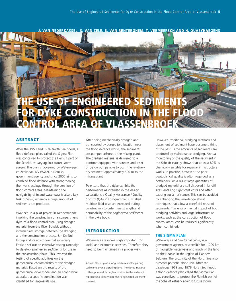
THE USE OF ENGINEERED SEDIMENTS FOR DYKE CONSTRUCTION IN THE FLOOD CONTROL AREA OF VLASSENBROEK
J. VAN NEDERKASSEL, S. VAN ZELE, B. VAN RENTERGHEM, T. VERMEERSCH AND H. QUAEYHAEGENS
Above: Close up of a long-reach excavator placing
sediments over a vibrating sieve. The sieved material
is then pumped through a pipeline to the sediment
reprocessing plant where the “engineered sediment”
is mixed.
The Use of Engineered Sediments for Dyke Construction in the Flood Control Area of Vlassenbroek 5
6 Terra et Aqua | Number 138 | March 2015
INNOVATIVE ANSWERIn civil construction a widespread technique is
to stabilise and solidify soft soils with additives
such as lime, fly ash or cement. It is not
uncommon that contaminated sediments are
stabilised and solidified prior to final disposal
in a landfill. Jan De Nul Group came up with
the innovative solution to bring the dredged
sediments ashore using high density pumps
and to create engineered sediments from the
soft not-suitable sediments by applying and
optimising the stabilisation and solidification
methodology.This technology, as applied to
the Vlassenbroek pilot project, has the
following advantages:
- No transport water and associated
environmental permitting for water
treatment is necessary.
- The dyke body can be built up with a high
proportion of sediments, minimizing external
supply and associated transport.
- Workability, shear strength and bearing
capacity of the sediments are quickly
improved.
- Permeability of the sediments is decreased
because of physical and chemical binding.
- Risk for internal slides is reduced as only one
type of dyke material is used.
- Internal settlements are reduced as no
dewatering takes place and the solidified
material gets its final shape in a couple of
days to weeks.
PILOT PROJECT ACTIVITIESThe Vlassenbroek pilot project execution can
be divided in four work stages:
1. Design phase
2. Construction phase
3. Quality control
4. Post-construction testing
Stage 1: Design PhaseDesign requirementsThe overflow dyke has to be 800 m long with
20/4 slopes. Crest width should be 7.0 m
wide and 4.5 m above ground level. The total
volume of the dyke body is estimated to be
100,000 m³. The design requirements for
the overflow dyke are equal to those for a
conventional dyke in tidal conditions. The
different failure mechanisms (see Figure 6)
that have to be addressed are:
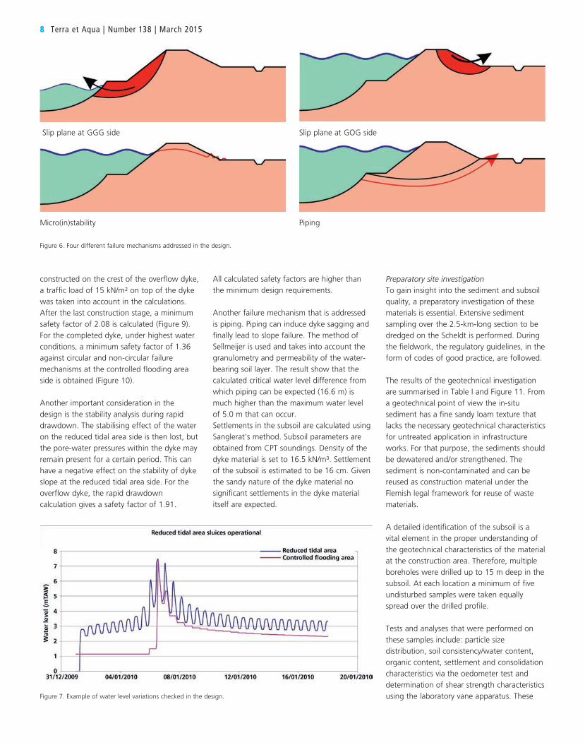
- Macro stability of the dyke slopes: formation
of slip planes between dyke body and
subsoil caused by uplifting phenomena.
outlined, providing the contractor with
non-contaminated sediment with a fine
granulometry that lacks the necessary
geotechnical characteristics for untreated
application in infrastructure works. The
overflow dyke, as secondary flood defence
structure, was selected to implement the
pilot project.
To encourage the innovativeness of the
market, W&Z set up a Design/Build project
through an open procedure in which the
client specifies certain requirements but the
contractor is free to pursue unique solutions.
In this case, in addition to price, the amount
of dredged material being reused and the
technical and environmental quality of
the bid were assessed in the course of the
procurement procedure to select the most
economically advantageous tender.
Bidders were asked to develop and implement
a method to dredge, transport and reuse
dredged material to construct the overflow
dyke within a framework of strict boundary
conditions. The shape of the overflow dyke
was prescribed as well as the minimum
requirements in relation to the impermeability
and micro as well as macro stability. After
being dredged the material was to be
transported either via the waterway or
through pipelines to the construction site for
immediate application. Intermediate storage
was excluded to minimise the environmental
impact of the construction works.
surges. The implementation of the Sigma Plan
is one of the key tasks of Waterways and Sea
Canal. Since 2005 flood defense is combined
with strengthening the river’s ecology through
the creation of flood control areas (FCA). To
construct new embankments around the first
series of flood control areas approximately 2.5
million m³ of construction material is needed.
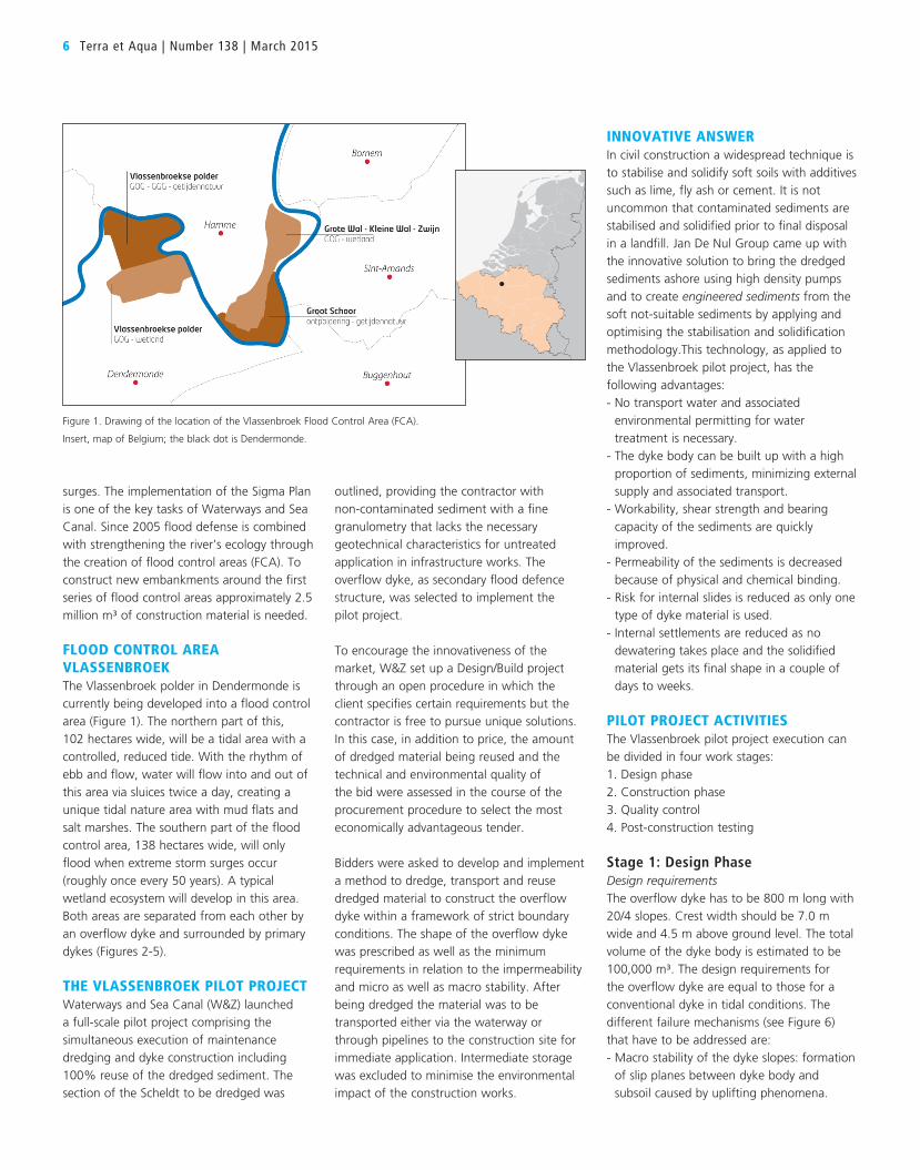
FLOOD CONTROL AREA VLASSENBROEKThe Vlassenbroek polder in Dendermonde is
currently being developed into a flood control
area (Figure 1). The northern part of this,
102 hectares wide, will be a tidal area with a
controlled, reduced tide. With the rhythm of
ebb and flow, water will flow into and out of
this area via sluices twice a day, creating a
unique tidal nature area with mud flats and
salt marshes. The southern part of the flood
control area, 138 hectares wide, will only
flood when extreme storm surges occur
(roughly once every 50 years). A typical
wetland ecosystem will develop in this area.
Both areas are separated from each other by
an overflow dyke and surrounded by primary
dykes (Figures 2-5).
THE VLASSENBROEK PILOT PROJECTWaterways and Sea Canal (W&Z) launched
a full-scale pilot project comprising the
simultaneous execution of maintenance
dredging and dyke construction including
100% reuse of the dredged sediment. The
section of the Scheldt to be dredged was
Figure 1. Drawing of the location of the Vlassenbroek Flood Control Area (FCA).
Insert, map of Belgium; the black dot is Dendermonde.
- Micro stability of the dyke slopes: formation
of slip planes in the dyke body caused by
infiltrating water.
- Piping: erosion of subsoil caused by ground
water flow carrying ground particles under
dyke body.
Stability has to be determined for both the
construction phase as well as for the final
situation. A minimum safety factor of 1.1 is
required for undrained scenarios during
construction; for the drained scenario upon
completion a minimum safety of 1.3 is
required.
Boundary conditions for the stability as well
as permeability of the overflow dyke are
governed by normative water levels that
might occur in the flood control area of
Vlassenbroek during storm events (see
Figure 7). One of the storm events that has
to be addressed for the calculation is the
unlikely event in which the reduced tidal area
is operating normally (water can flow in and
out through the sluices connected with
Scheldt) and the controlled flooding area has
continuously high water for 7 consecutive
days (outgoing sluice is closed).
Settlement at the location of the overflow
dyke had to be checked and incorporated in
the design.
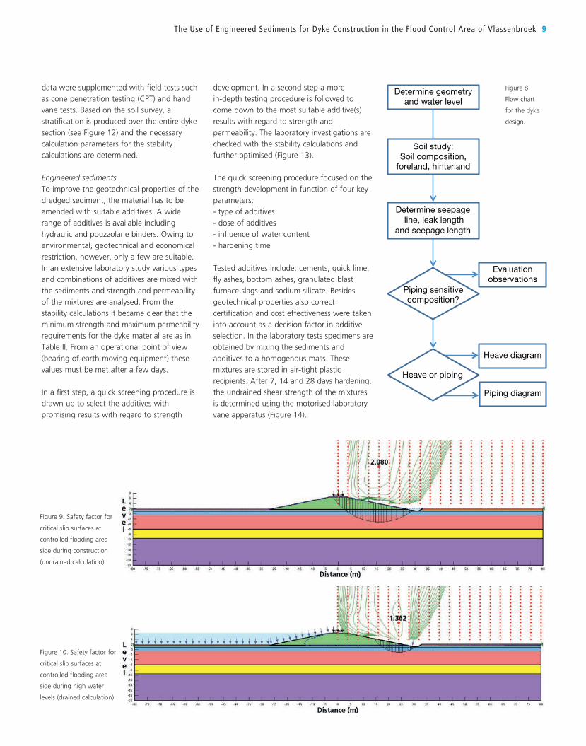
Stability calculationsThe flow scheme shown in Figure 8 is
followed during the design calculations.
Stability calculations are performed with
SLOPE/W software and seepage modelling is
performed with SEEP/W. Input parameters for
subsoil and dyke material are gathered from
laboratory and field investigations.
The results of the transient seepage modelling
show that the water flow in the overflow
dyke is negligible in all scenarios. For example,
in the worst case event with seven days of
continuous high water in the controlled tidal
area and the controlled flooding area empty,
the water flow in the overflow dyke is
1.49E-07 m³/s/m dyke.
The modelled water table is subsequently
used in the stability calculations to determine
the critical circular and non-circular failure
mechanisms via the Bishop method. Given the
fact that a 3.5-m wide service road will be
JORIS VAN NEDERKASSEL
graduated as a MSc in Bioscience
Engineering from Catholic University (KU)
Leuven in 2006 and started at Jan De Nul
Group as an environmental surveyor in the
Middle East and Australia. In 2009 he
moved to the Belgian office to follow up
on tenders and ongoing projects. In 2011
he became Project Engineer R&D at
Envisan, JDN’s environmental subsidiary.
SOFIE VAN ZELE
graduated in Industrial Engineering,
Hogeschool Ghent in 2000 and worked in
Ireland on remediation projects. She joined
the Jan De Nul Group in 2011 in the
Environmental Dredging Division and was
project manager during the construction of
the Moen sediment treatment centre and
the compartment dyke in Vlassenbroek,
where she now manages the dyke
construction.
BRAM VAN RENTERGHEM
obtained an MSc in Bioscience Engineering
and in Environmental Remediation and
Management from University of Ghent in
2004. In 2006 he joined the Jan De Nul
Group as an environmental engineer and
since 2008 is an operational dredging
superintendent. He was outsourced for 3
years to Envisan as a Project Manager and
as such followed up at Vlassenbroek.
TOM VERMEERSCH
graduated in 2009 with a MSc in Civil
Engineering from the University of Ghent
and joined the Design and Engineering
Department of the Jan De Nul Group. He
has worked as Design Engineer on civil and
dredging projects such as the Ivoz-Ramet
Lock and flood control dykes in Vlassen-
broek and the tender for the Fehmarnbelt
Tunnel between Denmark and Germany.
HANS QUAEYHAEGENS
obtained an MSc in Bio Engineering at the
University of Louvain, Belgium in 2004 and
then worked as a project manager on
environmental remediation projects in
Belgium and France. In 2007 he joined the
Flemish government agency Waterwegen
& Zeekanaal as project engineer on
projects that are part of the Sigma Plan,
the Flemish flood protection programme.
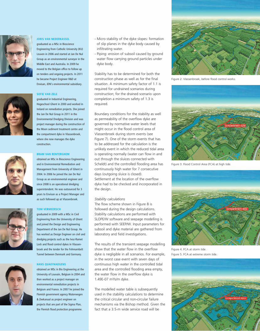
Figure 2. Vlassenbroek, before flood control works.
Figure 3. Flood Control Area (FCA) at high tide.
Figure 4. FCA at storm tide.
Figure 5. FCA at extreme storm tide.
8 Terra et Aqua | Number 138 | March 2015
All calculated safety factors are higher than
the minimum design requirements.
Another failure mechanism that is addressed
is piping. Piping can induce dyke sagging and
finally lead to slope failure. The method of
Sellmeijer is used and takes into account the
granulometry and permeability of the water-
bearing soil layer. The result show that the
calculated critical water level difference from
which piping can be expected (16.6 m) is
much higher than the maximum water level
of 5.0 m that can occur.
Settlements in the subsoil are calculated using
Sanglerat’s method. Subsoil parameters are
obtained from CPT soundings. Density of the
dyke material is set to 16.5 kN/m³. Settlement
of the subsoil is estimated to be 16 cm. Given
the sandy nature of the dyke material no
significant settlements in the dyke material
itself are expected.
constructed on the crest of the overflow dyke,
a traffic load of 15 kN/m² on top of the dyke
was taken into account in the calculations.
After the last construction stage, a minimum
safety factor of 2.08 is calculated (Figure 9).
For the completed dyke, under highest water
conditions, a minimum safety factor of 1.36
against circular and non-circular failure
mechanisms at the controlled flooding area
side is obtained (Figure 10).
Another important consideration in the
design is the stability analysis during rapid
drawdown. The stabilising effect of the water
on the reduced tidal area side is then lost, but
the pore-water pressures within the dyke may
remain present for a certain period. This can
have a negative effect on the stability of dyke
slope at the reduced tidal area side. For the
overflow dyke, the rapid drawdown
calculation gives a safety factor of 1.91.
Preparatory site investigationTo gain insight into the sediment and subsoil
quality, a preparatory investigation of these
materials is essential. Extensive sediment
sampling over the 2.5-km-long section to be
dredged on the Scheldt is performed. During
the fieldwork, the regulatory guidelines, in the
form of codes of good practice, are followed.
The results of the geotechnical investigation
are summarised in Table I and Figure 11. From
a geotechnical point of view the in-situ
sediment has a fine sandy loam texture that
lacks the necessary geotechnical characteristics
for untreated application in infrastructure
works. For that purpose, the sediments should
be dewatered and/or strengthened. The
sediment is non-contaminated and can be
reused as construction material under the
Flemish legal framework for reuse of waste
materials.
A detailed identification of the subsoil is a
vital element in the proper understanding of
the geotechnical characteristics of the material
at the construction area. Therefore, multiple
boreholes were drilled up to 15 m deep in the
subsoil. At each location a minimum of five
undisturbed samples were taken equally
spread over the drilled profile.
Tests and analyses that were performed on
these samples include: particle size
distribution, soil consistency/water content,
organic content, settlement and consolidation
characteristics via the oedometer test and
determination of shear strength characteristics
using the laboratory vane apparatus. These
Slip plane at GGG side
Micro(in)stability
Slip plane at GOG side
Piping
Figure 6. Four different failure mechanisms addressed in the design.
Figure 7. Example of water level variations checked in the design.
The Use of Engineered Sediments for Dyke Construction in the Flood Control Area of Vlassenbroek 9
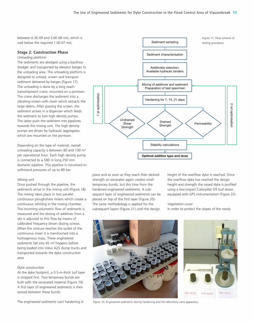
development. In a second step a more
in-depth testing procedure is followed to
come down to the most suitable additive(s)
results with regard to strength and
permeability. The laboratory investigations are
checked with the stability calculations and
further optimised (Figure 13).
The quick screening procedure focused on the
strength development in function of four key
parameters:
- type of additives
- dose of additives
- influence of water content
- hardening time
Tested additives include: cements, quick lime,
fly ashes, bottom ashes, granulated blast
furnace slags and sodium silicate. Besides
geotechnical properties also correct
certification and cost effectiveness were taken
into account as a decision factor in additive
selection. In the laboratory tests specimens are
obtained by mixing the sediments and
additives to a homogenous mass. These
mixtures are stored in air-tight plastic
recipients. After 7, 14 and 28 days hardening,
the undrained shear strength of the mixtures
is determined using the motorised laboratory
vane apparatus (Figure 14).
Soil study: Soil composition,
foreland, hinterland
Determine geometry and water level
Determine seepage line, leak length
and seepage length
Piping sensitive composition?
Evaluation observations
Heave or piping
Heave diagram
Piping diagram
Figure 8.
Flow chart
for the dyke
design.
Figure 9. Safety factor for
critical slip surfaces at
controlled flooding area
side during construction
(undrained calculation).
Figure 10. Safety factor for
critical slip surfaces at
controlled flooding area
side during high water
levels (drained calculation).
data were supplemented with field tests such
as cone penetration testing (CPT) and hand
vane tests. Based on the soil survey, a
stratification is produced over the entire dyke
section (see Figure 12) and the necessary
calculation parameters for the stability
calculations are determined.
Engineered sedimentsTo improve the geotechnical properties of the
dredged sediment, the material has to be
amended with suitable additives. A wide
range of additives is available including
hydraulic and pouzzolane binders. Owing to
environmental, geotechnical and economical
restriction, however, only a few are suitable.
In an extensive laboratory study various types
and combinations of additives are mixed with
the sediments and strength and permeability
of the mixtures are analysed. From the
stability calculations it became clear that the
minimum strength and maximum permeability
requirements for the dyke material are as in
Table II. From an operational point of view
(bearing of earth-moving equipment) these
values must be met after a few days.
In a first step, a quick screening procedure is
drawn up to select the additives with
promising results with regard to strength
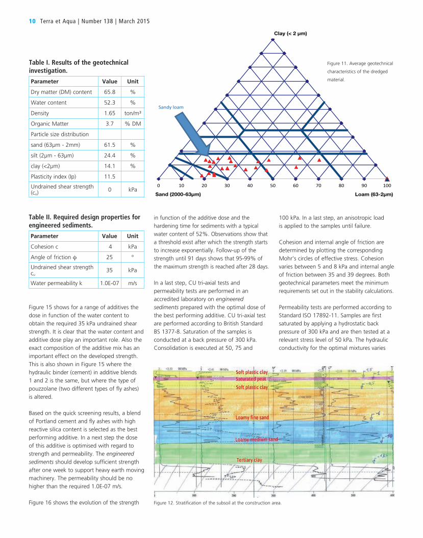
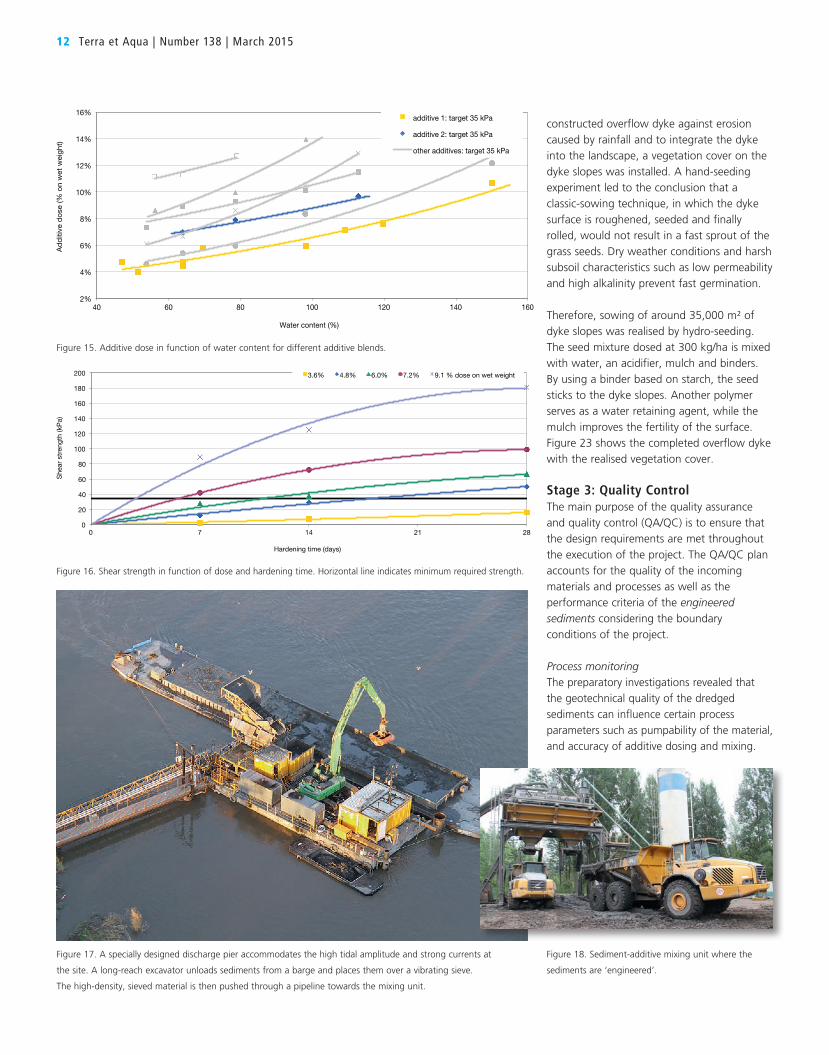
Figure 15 shows for a range of additives the
dose in function of the water content to
obtain the required 35 kPa undrained shear
strength. It is clear that the water content and
additive dose play an important role. Also the
exact composition of the additive mix has an
important effect on the developed strength.
This is also shown in Figure 15 where the
hydraulic binder (cement) in additive blends
1 and 2 is the same, but where the type of
pouzzolane (two different types of fly ashes)
is altered.
Based on the quick screening results, a blend
of Portland cement and fly ashes with high
reactive silica content is selected as the best
performing additive. In a next step the dose
of this additive is optimised with regard to
strength and permeability. The engineered sediments should develop sufficient strength
after one week to support heavy earth moving
machinery. The permeability should be no
higher than the required 1.0E-07 m/s.
Figure 16 shows the evolution of the strength
in function of the additive dose and the
hardening time for sediments with a typical
water content of 52%. Observations show that
a threshold exist after which the strength starts
to increase exponentially. Follow-up of the
strength until 91 days shows that 95-99% of
the maximum strength is reached after 28 days.
In a last step, CU tri-axial tests and
permeability tests are performed in an
accredited laboratory on engineered sediments prepared with the optimal dose of
the best performing additive. CU tri-axial test
are performed according to British Standard
BS 1377-8. Saturation of the samples is
conducted at a back pressure of 300 kPa.
Consolidation is executed at 50, 75 and
100 kPa. In a last step, an anisotropic load
is applied to the samples until failure.
Cohesion and internal angle of friction are
determined by plotting the corresponding
Mohr’s circles of effective stress. Cohesion
varies between 5 and 8 kPa and internal angle
of friction between 35 and 39 degrees. Both
geotechnical parameters meet the minimum requirements set out in the stability calculations.
Permeability tests are performed according to
Standard ISO 17892-11. Samples are first
saturated by applying a hydrostatic back
pressure of 300 kPa and are then tested at a
relevant stress level of 50 kPa. The hydraulic
conductivity for the optimal mixtures varies
10 Terra et Aqua | Number 138 | March 2015
Table II. Required design properties for engineered sediments.
Parameter Value Unit
Cohesion c 4 kPa
Angle of friction φ 25 °
Undrained shear strength cu
35 kPa
Water permeability k 1.0E-07 m/s
Table I. Results of the geotechnical investigation.
Parameter Value Unit
Dry matter (DM) content 65.8 %
Water content 52.3 %
Density 1.65 ton/m³
Organic Matter 3.7 % DM
Particle size distribution
sand (63µm - 2mm) 61.5 %
silt (2µm - 63µm) 24.4 %
clay (<2µm) 14.1 %
Plasticity index (Ip) 11.5
Undrained shear strength (cu)
0 kPa
Figure 12. Stratification of the subsoil at the construction area.
0 10 20 30 40 50 60 70 80 90 100
Clay (< 2 µm)
Sand (2000-63µm) Loam (63-2µm)
Sandy loam
Figure 11. Average geotechnical
characteristics of the dredged
material.
between 6.3E-09 and 3.6E-08 m/s, which is
well below the required 1.0E-07 m/s.
Stage 2: Construction PhaseUnloading platformThe sediments are dredged using a backhoe
dredger and transported by elevator barges to
the unloading area. The unloading platform is
designed to unload, screen and transport
sediment delivered by barges (Figure 17).
The unloading is done by a long reach
transshipment crane, mounted on a pontoon.
The crane discharges the sediment into a
vibrating screen with mesh which extracts the
large debris. After passing the screen, the
sediment arrives in a dispenser which feeds
the sediment to two high density pumps.
The latter push the sediment into pipelines
towards the mixing unit. The high density
pumps are driven by hydraulic aggregates,
which are mounted on the pontoon.
Depending on the type of material, overall
unloading capacity is between 80 and 130 m³
per operational hour. Each high density pump
is connected to a 580 m long 250 mm
diameter pipeline. This pipeline is conceived to
withstand pressures of up to 80 bar.
Mixing unitOnce pushed through the pipeline, the
sediments arrive in the mixing unit (Figure 18).
The mixing takes place in two parallel
continuous ploughshare mixers which create a
continuous whirling in the mixing chamber.
The incoming volumetric flow of sediments is
measured and the dosing of additives from a
silo is adjusted to this flow by means of
calibrated frequency driven dozing screws.
When the mixture reaches the outlet of the
continuous mixer it is transformed into a
homogenous mass. These engineered sediments fall into 45 m³ hoppers before
being loaded into Volvo A25 dump trucks and
transported towards the dyke construction
area.
Dyke constructionAt the dyke footprint, a 0.5-m-thick turf layer
is stripped first. Two temporary bunds are
built with the excavated material (Figure 19).
A first layer of engineered sediments is then
spread between these bunds.
The engineered sediments start hardening in
place and as soon as they reach their desired
strength an excavator again creates small
temporary bunds, but this time from the
hardened engineered sediments. A sub-
sequent layer of engineered sediments can be
placed on top of the first layer (Figure 20).
The same methodology is applied for the
subsequent layers (Figure 21) until the design
height of the overflow dyke is reached. Once
the overflow dyke has reached the design
height and strength the raised dyke is profiled
using a low-impact Caterpillar D5 bull dozer, equipped with GPS instrumentation (Figure 22).
Vegetation coverIn order to protect the slopes of the newly
The Use of Engineered Sediments for Dyke Construction in the Flood Control Area of Vlassenbroek 11
Figure 14. Engineered sediments during hardening and the laboratory vane apparatus.
Sediment sampling
Undrained Shear
Strength
Sediment characterisation
Additive(s) selection: Available hydraulic binders
Mixing of additives and sediment Preparation of test specimen
Hardening for 7, 14, 21 days
Drained Strength
Permeability
Stability calculations
Optimal additive type and dose
1 st
op
timis
atio
n
2 nd op
timisation
Figure 13. Flow scheme of
testing procedure.
12 Terra et Aqua | Number 138 | March 2015
constructed overflow dyke against erosion
caused by rainfall and to integrate the dyke
into the landscape, a vegetation cover on the
dyke slopes was installed. A hand-seeding
experiment led to the conclusion that a
classic-sowing technique, in which the dyke
surface is roughened, seeded and finally
rolled, would not result in a fast sprout of the
grass seeds. Dry weather conditions and harsh
subsoil characteristics such as low permeability
and high alkalinity prevent fast germination.
Therefore, sowing of around 35,000 m² of
dyke slopes was realised by hydro-seeding.
The seed mixture dosed at 300 kg/ha is mixed
with water, an acidifier, mulch and binders.
By using a binder based on starch, the seed
sticks to the dyke slopes. Another polymer
serves as a water retaining agent, while the
mulch improves the fertility of the surface.
Figure 23 shows the completed overflow dyke
with the realised vegetation cover.
Stage 3: Quality Control The main purpose of the quality assurance
and quality control (QA/QC) is to ensure that
the design requirements are met throughout
the execution of the project. The QA/QC plan
accounts for the quality of the incoming
materials and processes as well as the
performance criteria of the engineered sediments considering the boundary
conditions of the project.
Process monitoringThe preparatory investigations revealed that
the geotechnical quality of the dredged
sediments can influence certain process
parameters such as pumpability of the material,
and accuracy of additive dosing and mixing.
2%
4%
6%
8%
10%
12%
14%
16%
40 60 80 100 120
Ad
diti
ve d
ose
(% o
n w
et w
eig
ht)
Water content (%)
140 160
additive 1: target 35 kPa
additive 2: target 35 kPa
other additives: target 35 kPa
0
20
40
60
80
100
120
140
160
180
200
0 7 14
She
ar s
tren
gth
(kP
a)
Hardening time (days)
3.6% 4.8% 6.0%
21 28
7.2% 9.1 % dose on wet weight
Figure 16. Shear strength in function of dose and hardening time. Horizontal line indicates minimum required strength.
Figure 17. A specially designed discharge pier accommodates the high tidal amplitude and strong currents at
the site. A long-reach excavator unloads sediments from a barge and places them over a vibrating sieve.
The high-density, sieved material is then pushed through a pipeline towards the mixing unit.
Figure 18. Sediment-additive mixing unit where the
sediments are ‘engineered’.
Figure 15. Additive dose in function of water content for different additive blends.
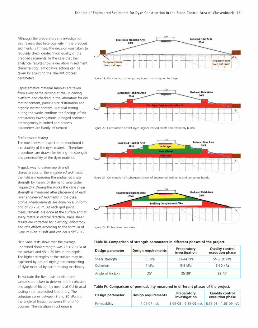
Although the preparatory site investigation
also reveals that heterogeneity in the dredged
sediments is limited, the decision was taken to
regularly check geotechnical quality of the
dredged sediments. In the case that the
analytical results show a deviation in sediment
characteristics, anticipative actions can be
taken by adjusting the relevant process
parameters.
Representative material samples are taken
from every barge arriving at the unloading
platform and checked in the laboratory for dry
matter content, particle size distribution and
organic matter content. Material testing
during the works confirms the findings of the
preparatory investigations: dredged sediment
heterogeneity is limited and process
parameters are hardly influenced.
Performance testingThe most relevant aspect to be monitored is
the stability of the dyke material. Therefore
procedures are drawn for testing the strength
and permeability of the dyke material.
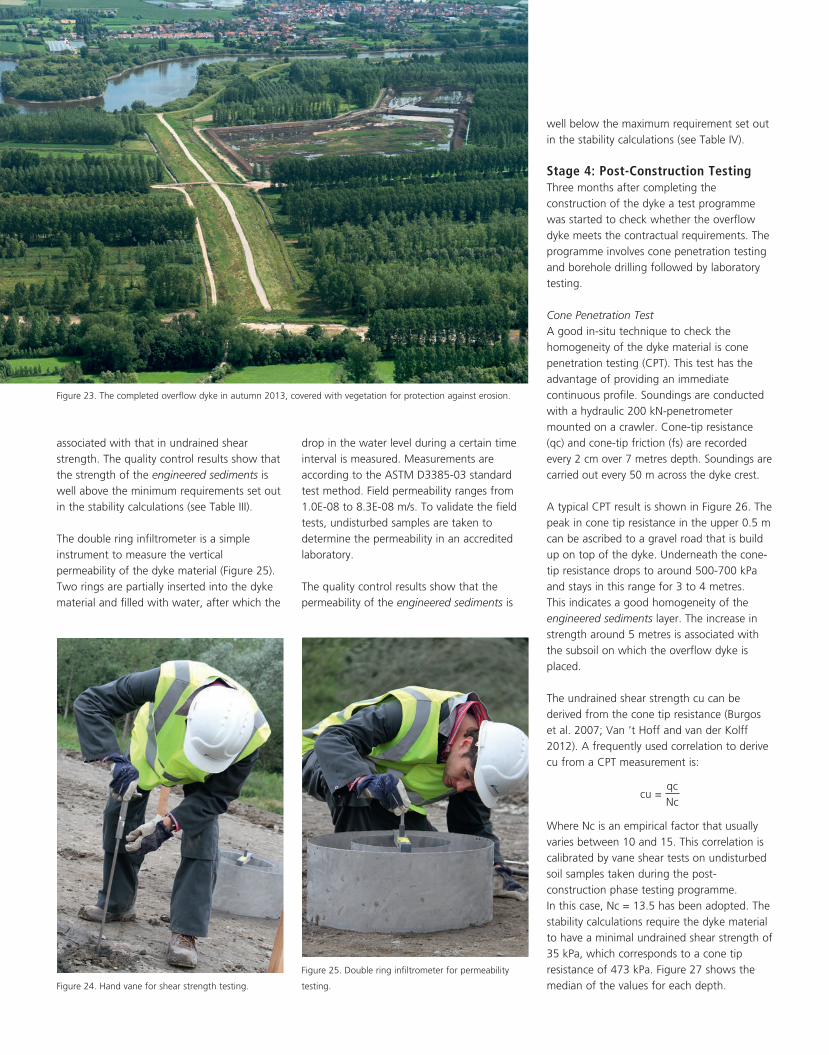
A quick way to determine strength
characteristics of the engineered sediments in
the field is measuring the undrained shear
strength by means of the hand vane tester
(Figure 24). During the works the vane shear
strength is measured after placement of each
layer engineered sediments in the dyke
profile. Measurements are done on a uniform
grid of 20 x 20 m. At each grid point
measurements are done at the surface and at
every metre in vertical direction. Vane shear
results are corrected for plasticity, anisotropy
and rate effects according to the formula of
Bjerrum (Van ’t Hoff and van der Kolff 2012).
Field vane tests show that the average
undrained shear strength was 76 ± 29 kPa at
the surface and 55 ± 20 kPa in the depth.
The higher strengths at the surface may be
explained by natural drying and compacting
of dyke material by earth moving machinery.
To validate the field tests, undisturbed
samples are taken to determine the cohesion
and angle of friction by means of CU tri-axial
testing in an accredited laboratory. The
cohesion varies between 8 and 30 kPa and
the angle of friction between 34 and 40
degrees. The variation in cohesion is
The Use of Engineered Sediments for Dyke Construction in the Flood Control Area of Vlassenbroek 13
Figure 22. Profiled overflow dyke.
Figure 21. Construction of subsequent layers of Engineered Sediments and temporary bunds.
Figure 20. Construction of first layer Engineered Sediments and temporary bunds.
Figure 19. Construction of temporary bunds from stripped turf layer.
Table III. Comparison of strength parameters in different phases of the project.
Design parameter Design requirements Preparatory investigation
Quality control execution phase
Shear strength 35 kPa 33-44 kPa 55 ± 20 kPa
Cohesion 4 kPa 5-8 kPa 8-30 kPa
Angle of friction 25˚ 35-39˚ 33-40˚
Table IV. Comparison of permeability measured in different phases of the project.
Design parameter Design requirements Preparatory investigation
Quality control execution phase
Permeability 1.0E-07 m/s 3.6E-08 - 6.3E-09 m/s 8.3E-08 - 1.6E-09 m/s
well below the maximum requirement set out
in the stability calculations (see Table IV).
Stage 4: Post-Construction TestingThree months after completing the
construction of the dyke a test programme
was started to check whether the overflow
dyke meets the contractual requirements. The
programme involves cone penetration testing
and borehole drilling followed by laboratory
testing.
Cone Penetration TestA good in-situ technique to check the
homogeneity of the dyke material is cone
penetration testing (CPT). This test has the
advantage of providing an immediate
continuous profile. Soundings are conducted
with a hydraulic 200 kN-penetrometer
mounted on a crawler. Cone-tip resistance
(qc) and cone-tip friction (fs) are recorded
every 2 cm over 7 metres depth. Soundings are
carried out every 50 m across the dyke crest.
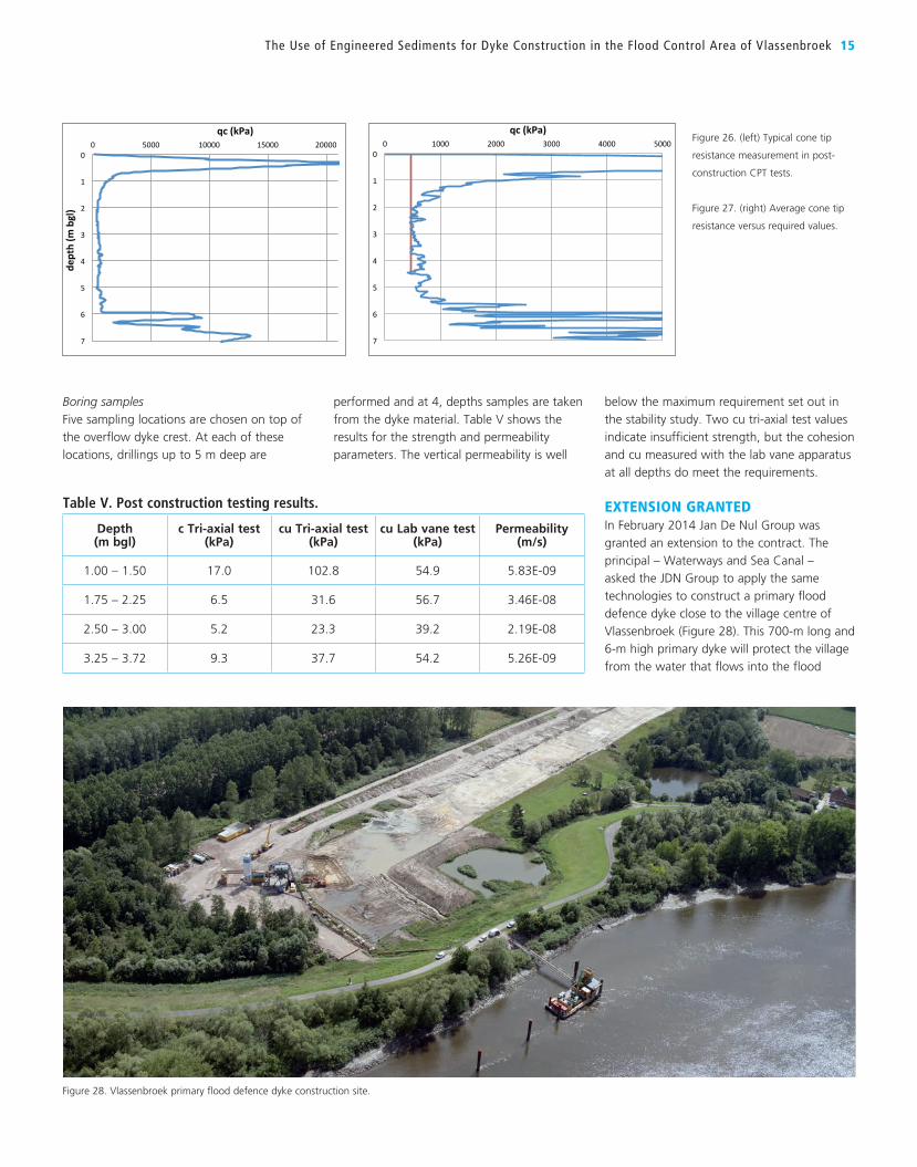
A typical CPT result is shown in Figure 26. The
peak in cone tip resistance in the upper 0.5 m
can be ascribed to a gravel road that is build
up on top of the dyke. Underneath the cone-
tip resistance drops to around 500-700 kPa
and stays in this range for 3 to 4 metres.
This indicates a good homogeneity of the
engineered sediments layer. The increase in
strength around 5 metres is associated with
the subsoil on which the overflow dyke is
placed.
The undrained shear strength cu can be
derived from the cone tip resistance (Burgos
et al. 2007; Van ’t Hoff and van der Kolff
2012). A frequently used correlation to derive
cu from a CPT measurement is:
cu =
qc
Nc
Where Nc is an empirical factor that usually
varies between 10 and 15. This correlation is
calibrated by vane shear tests on undisturbed
soil samples taken during the post-
construction phase testing programme.
In this case, Nc = 13.5 has been adopted. The
stability calculations require the dyke material
to have a minimal undrained shear strength of
35 kPa, which corresponds to a cone tip
resistance of 473 kPa. Figure 27 shows the
median of the values for each depth.
drop in the water level during a certain time
interval is measured. Measurements are
according to the ASTM D3385-03 standard
test method. Field permeability ranges from
1.0E-08 to 8.3E-08 m/s. To validate the field
tests, undisturbed samples are taken to
determine the permeability in an accredited
laboratory.
The quality control results show that the
permeability of the engineered sediments is
associated with that in undrained shear
strength. The quality control results show that
the strength of the engineered sediments is well above the minimum requirements set out
in the stability calculations (see Table III).
The double ring infiltrometer is a simple
instrument to measure the vertical
permeability of the dyke material (Figure 25).
Two rings are partially inserted into the dyke
material and filled with water, after which the
Figure 24. Hand vane for shear strength testing.
Figure 25. Double ring infiltrometer for permeability
testing.
Figure 23. The completed overflow dyke in autumn 2013, covered with vegetation for protection against erosion.
The Use of Engineered Sediments for Dyke Construction in the Flood Control Area of Vlassenbroek 15
below the maximum requirement set out in
the stability study. Two cu tri-axial test values
indicate insufficient strength, but the cohesion
and cu measured with the lab vane apparatus
at all depths do meet the requirements.
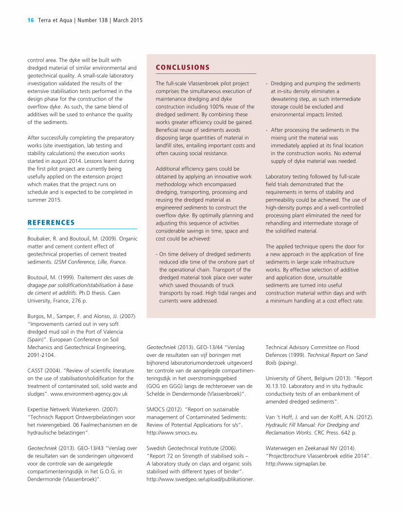
EXTENSION GRANTEDIn February 2014 Jan De Nul Group was
granted an extension to the contract. The
principal – Waterways and Sea Canal –
asked the JDN Group to apply the same
technologies to construct a primary flood
defence dyke close to the village centre of
Vlassenbroek (Figure 28). This 700-m long and
6-m high primary dyke will protect the village
from the water that flows into the flood
Boring samplesFive sampling locations are chosen on top of
the overflow dyke crest. At each of these
locations, drillings up to 5 m deep are
performed and at 4, depths samples are taken
from the dyke material. Table V shows the
results for the strength and permeability
parameters. The vertical permeability is well
0
1
2
3
4
5
6
7
0 5000 10000 15000 20000
dept
h (m
bgl
)
qc (kPa)
0
1
2
3
4
5
6
7
0 1000 2000 3000 4000 5000
dept
h (m
bgl
)
qc (kPa)
minimal required median
Figure 28. Vlassenbroek primary flood defence dyke construction site.
Figure 26. (left) Typical cone tip
resistance measurement in post-
construction CPT tests.
Figure 27. (right) Average cone tip
resistance versus required values.
Table V. Post construction testing results.
Depth(m bgl)
c Tri-axial test(kPa)
cu Tri-axial test(kPa)
cu Lab vane test(kPa)
Permeability(m/s)
1.00 – 1.50 17.0 102.8 54.9 5.83E-09
1.75 – 2.25 6.5 31.6 56.7 3.46E-08
2.50 – 3.00 5.2 23.3 39.2 2.19E-08
3.25 – 3.72 9.3 37.7 54.2 5.26E-09
16 Terra et Aqua | Number 138 | March 2015
Technical Advisory Committee on Flood
Defences (1999). Technical Report on Sand Boils (piping).
University of Ghent, Belgium (2013). “Report
XI.13.10. Laboratory and in situ hydraulic
conductivity tests of an embankment of
amended dredged sediments”.
Van ‘t Hoff, J. and van der Kolff, A.N. (2012).
Hydraulic Fill Manual: For Dredging and Reclamation Works. CRC Press. 642 p.
Waterwegen en Zeekanaal NV (2014).
“Projectbrochure Vlassenbroek editie 2014”.
http://www.sigmaplan.be.
Geotechniek (2013). GEO-13/44 “Verslag
over de resultaten van vijf boringen met
bijhorend laboratoriumonderzoek uitgevoerd
ter controle van de aangelegde compartimen-
teringsdijk in het overstromingsgebied
(GOG en GGG) langs de rechteroever van de
Schelde in Dendermonde (Vlassenbroek)”.
SMOCS (2012). “Report on sustainable
management of Contaminated Sediments:
Review of Potential Applications for s/s”.
http://www.smocs.eu.
Swedish Geotechnical Institute (2006).
“Report 72 on Strength of stabilised soils –
A laboratory study on clays and organic soils
stabilised with different types of binder”.
http://www.swedgeo.se/upload/publikationer.
control area. The dyke will be built with
dredged material of similar environmental and
geotechnical quality. A small-scale laboratory
investigation validated the results of the
extensive stabilisation tests performed in the
design phase for the construction of the
overflow dyke. As such, the same blend of
additives will be used to enhance the quality
of the sediments.
After successfully completing the preparatory
works (site investigation, lab testing and
stability calculations) the execution works
started in august 2014. Lessons learnt during
the first pilot project are currently being
usefully applied on the extension project
which makes that the project runs on
schedule and is expected to be completed in
summer 2015.
REFERENCES
Boubaker, R. and Boutouil, M. (2009). Organic
matter and cement content effect of
geotechnical properties of cement treated
sediments. I2SM Conference, Lille, France.
Boutouil, M. (1999). Traitement des vases de dragage par solidification/stabilisation à base de ciment et additifs. Ph.D thesis. Caen
University, France, 276 p.
Burgos, M., Samper, F. and Alonso, JJ. (2007).
“Improvements carried out in very soft
dredged mud soil in the Port of Valencia
(Spain)”. European Conference on Soil
Mechanics and Geotechnical Engineering,
2091-2104.
CASST (2004). “Review of scientific literature on the use of stabilisation/solidification for the
treatment of contaminated soil, solid waste and
sludges”. www.environment-agency.gov.uk
Expertise Netwerk Waterkeren. (2007).
“Technisch Rapport Ontwerpbelastingen voor
het rivierengebied. 06 Faalmechanismen en de
hydraulische belastingen”.
Geotechniek (2013). GEO-13/43 “Verslag over
de resultaten van de sonderingen uitgevoerd
voor de controle van de aangelegde
compartimenteringsdijk in het G.O.G. in
Dendermonde (Vlassenbroek)”.
CONCLUSIONS
The full-scale Vlassenbroek pilot project
comprises the simultaneous execution of
maintenance dredging and dyke
construction including 100% reuse of the
dredged sediment. By combining these
works greater efficiency could be gained.
Beneficial reuse of sediments avoids
disposing large quantities of material in
landfill sites, entailing important costs and
often causing social resistance.
Additional efficiency gains could be
obtained by applying an innovative work
methodology which encompassed
dredging, transporting, processing and
reusing the dredged material as
engineered sediments to construct the
overflow dyke. By optimally planning and
adjusting this sequence of activities
considerable savings in time, space and
cost could be achieved:
- On time delivery of dredged sediments
reduced idle time of the onshore part of
the operational chain. Transport of the
dredged material took place over water
which saved thousands of truck
transports by road. High tidal ranges and
currents were addressed.
- Dredging and pumping the sediments
at in-situ density eliminates a
dewatering step, as such intermediate
storage could be excluded and
environmental impacts limited.
- After processing the sediments in the
mixing unit the material was
immediately applied at its final location
in the construction works. No external
supply of dyke material was needed.
Laboratory testing followed by full-scale
field trials demonstrated that the
requirements in terms of stability and
permeability could be achieved. The use of
high-density pumps and a well-controlled
processing plant eliminated the need for
rehandling and intermediate storage of
the solidified material.
The applied technique opens the door for
a new approach in the application of fine
sediments in large scale infrastructure
works. By effective selection of additive
and application dose, unsuitable
sediments are turned into useful
construction material within days and with
a minimum handling at a cost effect rate.