the use of representation clauses and implementation ... · pdf filetation clauses and...
TRANSCRIPT

Technical Report
CMU/SEI-87-TR-14ESD-TR-87-115
The Use of Representation Clausesand Implementation-DependentFeatures in Ada:
I. OverviewB. Craig Meyers
Andrea L. Cappellini
July 1987

The Use of Representation Clausesand Implementation-Dependent
Features in Ada:I. Overview
��
Software Engineering InstituteCarnegie Mellon University
Pittsburgh, Pennsylvania 15213
Technical ReportCMU/SEI-87-TR-14
ESD/TR-87-115July 1987
B. Craig MeyersAndrea L. Cappellini
Ada Embedded Systems Testbed Project
Unlimited distribution subject to the copyright.

This report was prepared for the SEI Joint Program Office HQ ESC/AXS
5 Eglin Street
Hanscom AFB, MA 01731-2116
The ideas and findings in this report should not be construed as an official DoD position. It ispublished in the interest of scientific and technical information exchange.
FOR THE COMMANDER
(signature on file)
Thomas R. Miller, Lt Col, USAF, SEI Joint Program Office
This work is sponsored by the U.S. Department of Defense.
Copyright 1987 by Carnegie Mellon University.
Permission to reproduce this document and to prepare derivative works from this document for internal use is granted, provided the copyright and \‘No Warranty\’
statements are included with all reproductions and derivative works. Requests for permission to reproduce this document or to prepare derivative works of this document
for external and commercial use should be addressed to the SEI Licensing Agent.
NO WARRANTY
THIS CARNEGIE MELLON UNIVERSITY AND SOFTWARE ENGINEERING INSTITUTE MATERIAL IS FURNISHED ON AN \‘AS-IS\’ BASIS. CARNEGIE MELLON
UNIVERSITY MAKES NO WARRANTIES OF ANY KIND, EITHER EXPRESSED OR IMPLIED, AS TO ANY MATTER INCLUDING, BUT NOT LIMITED TO,
WARRANTY OF FITNESS FOR PURPOSE OR MERCHANTIBILITY, EXCLUSIVITY, OR RESULTS OBTAINED FROM USE OF THE MATERIAL. CARNEGIE MELLON
UNIVERSITY DOES NOT MAKE ANY WARRANTY OF ANY KIND WITH RESPECT TO FREEDOM FROM PATENT, TRADEMARK, OR COPYRIGHT
INFRINGEMENT.
This work was created in the performance of Federal Government Contract Number F19628-95-C-0003 with Carnegie Mellon University for the operation of the Software
Engineering Institute, a federally funded research and development center. The Government of the United States has a royalty-free government-purpose license to use,
duplicate, or disclose the work, in whole or in part and in any manner, and to have or permit others to do so, for government purposes pursuant to the copyright license
under the clause at 52.227-7013.
This document is available through Research Access, Inc. / 800 Vinial Street / Pittsburgh, PA 15212. Phone: 1-800-685-6510. FAX: (412) 321-2994. RAI also maintains
a World Wide Web home page at http://www.rai.com
Copies of this document are available through the National Technical Information Service (NTIS). For information on ordering, please contact NTIS directly: National
Technical Information Service / U.S. Department of Commerce / Springfield, VA 22161. Phone: (703) 487-4600.
This document is also available through the Defense Technical Information Center (DTIC). DTIC provides acess to and transfer of scientific and technical information for
DoD personnel, DoD contractors and potential con tractors, and other U.S. Government agency personnel and their contractors. To obtain a copy, please contact DTIC
directly: Defense Technical Information Center / 8725 John J. Kingman Road / Suite 0944 / Ft. Belvoir, VA 22060-6218. Phone: 1-800-225-3842 or 703-767-8222.
Use of any trademarks in this report is not intended in any way to infringe on the rights of the trademark holder.

CMU/SEI-TR-14 1
The Use of Representation Clausesand Implementation-Dependent Features
in Ada:I. Overview
Abstract: This report, the first in a series, presents an overview of the aspects of the Adalanguage relating to representation clauses and implementation-dependent features. Par-ticular emphasis is given to the use of Ada for application to packed data structures. Thisreport is in part tutorial, and several examples from real-time, mission-critical systems arediscussed in detail. A brief discussion of design guidelines for the use of representationclauses and implementation-dependent features is included.
1. Introduction
The Ada language has now been mandated by the Department of Defense (DoD) for use in real-time,mission-critical systems as noted in reference [1]. There are many issues which must be givenconsideration for the application of Ada to such systems. These issues apply to the compiler as wellas the run-time environment support.
It is the purpose of this report to present a discussion of the issues relating to the use of represen-tation clauses and implementation-dependent features in Ada. The discussion is based on examplesfrom characteristic real-time, mission-critical systems. This discussion is in part tutorial. That is, abrief overview of the aspects of Ada relating to representation clauses and implementation-dependentfeatures is provided. Additionally, examples are discussed from a tutorial viewpoint. In this sense,this report may serve as an introduction to the use of representation clauses and implementation-dependent features in Ada.
This report is organized in the following manner: Chapter 2 provides an overview of the problemdomain to which representation clauses and implementation-dependent features are applicable.Chapter 3 gives an overview of those features of the Ada language which are applicable to thisdomain. A basic design principle, and the use of representation clauses from a global perspective,are provided in Chapter 4. Chapter 5 presents several case study examples of the use of represen-tation clauses and implementation-dependent features. The use of assembler language is discussedin Chapter 6. Chapter 7 lists a set of design guidelines for considered use of representation clausesand implementation-dependent features. A summary of the report appears in Chapter 8. Finally,Appendix I groups together the figures for this report to improve the continuity of the text.
This is the first in a series of reports dealing with the use of representation clauses andimplementation-dependent features in Ada. The principal focus of the present report is in part tutorialand case study in nature. The second report, reference [2], provides a set of questions deemedrelevant to the evaluation of support for representation clauses and implementation-dependent fea-

2 CMU/SEI-87-TR-14
tures provided by an Ada compiler. These questions are then related to a general experimentalcontext described in reference [3]. A qualitative assessment of the VAX Ada compiler may be found inreference [4]. In summary, references [2] and [3] provide a basis for evaluation of a particular Adacompiler with regard to representation clauses and implementation-dependent features. This schememay be applied to other compilers, and other qualitative compiler assessments are expected to ap-pear as part of this series.
This report has been prepared by the Ada Embedded Systems Testbed Project at the SoftwareEngineering Institute (SEI). The SEI is a federally funded research and development center (FFRDC)sponsored by the DoD and established and operated by Carnegie Mellon University. This report wasprepared by the authors while on sabbatical leave at the SEI.

CMU/SEI-TR-14 3
2. The Problem Domain
A frequent characteristic of real-time, embedded systems is that they make use of packed datastructures. That is, the basic unit of machine storage (such as a 16-bit word) may be used to storeseveral fields. For example, a storage unit may contain several values such as a 4-bit integer, a 2-bitinteger and a 10-bit integer. Additionally, one frequently encounters "binary scaled" values. Theseare fixed-point objects represented in the form (m, n), meaning there are m binary digits to the left ofthe (binary) decimal place, and n binary digits to the right. Thus, scalings such as (7, 8), (0, 15), and(17, 10) may be found. The application program must therefore provide code which accesses,manipulates, and performs arithmetic operations on such data structures.
The principal reasons for the use of packed data structures are two-fold, namely:
1. To minimize storage allocation.
2. To conform to constraints imposed by external systems.
The first case is obvious. That is, storage availability is at a premium in many systems and minimiz-ing such storage allocation is often a basic concern. It is understood that the particular application iswilling to sacrifice additional time to perform the storage operations on the packed data structures.
A second reason for the use of packed data structures is to conform to the requirements imposed bysome external system. A relevant example is some hardware device that memory maps data in apacked format which the application program must then operate on. In these cases, there is nofreedom of choice regarding data representation on behalf of the application program. That is, thereis an explicit requirement that the application must process and perform operations on such packeddata structures.
Many mission-critical systems are distributed in nature. For example, a command and control systemmay be composed of several subsystems. A basic feature of the overall system is that the subsys-tems communicate via digital intercomputer messages. Often the content of the messages trans-mitted and received by a particular subsystem employ packed data structures. Thus, a particularapplication subsystem must be able to process packed data structures; this represents the casewhere the application is constrained to conform to requirements imposed by existing systems. Theuse of packed data structures within the context of intercomputer messages motivates the examplesdiscussed later in this report.
The ability to access and perform operations on packed data structures is directly related to Ada andmay be illustrated as follows. Consider a distributed system which is composed of subsystems,possibly resident in different processors. Assume that one of the subsystems will be upgraded andthat the upgrade will be done using Ada. Clearly, the new upgrade must conform to interfacespecifications with other existing subsystems. Hence, if interprocessor communication is achieved bypacked data structures, the upgrade must also conform to the requirements imposed by the existingsubsystems. In other words, the ability of the Ada compiler chosen for the upgrade to access andoperate on packed data structures is an issue which must be addressed.

4 CMU/SEI-87-TR-14

CMU/SEI-TR-14 5
3. Discussion of Representation Clauses andImplementation-Dependent Features in Ada
3.1. Introduction
One of the underlying design principles in the development of the Ada language was the attempt toincorporate accepted software engineering practice in elements of the language. One of these prin-ciples, as discussed in reference [5], is referred to as the "separation principle." That is, one shouldattempt to separate the logical data representation from the physical representation. The logicalrepresentation refers to the conceptual, structural representation of data and is machine independent.In contrast, the physical representation couples the logical representation to the underlying architec-ture.
It was recognized, however, that there was a need to be able to allow the designer to interact with theunderlying hardware implementation of data types. For this reason Ada provides representationclauses which provide the mechanism through which the logical properties of data types may bemapped to the underlying machine architecture. It is through the use of the representation clausesthat packed data structures may be discussed in Ada. The discussion of representation clauses andimplementation-dependent features constitutes the so-called "Chapter 13" issues of Ada, as dis-cussed in the Reference Manual for the Ada Programming Language, reference [6].
An important point must be made at the outset of any discussion of representation clauses andimplementation-dependent features in Ada. The reader must be aware that the use of these lan-guage features will considerably affect the portability of the software. Specifically, the use ofrepresentation clauses manifests a direct coupling to the underlying architecture. As such, the codewill be machine-dependent, and portability of the code may no longer be possible. Theimplementation-dependent features are, by definition, implementation specific. The loss of portabilitymust be kept in mind; in many cases of embedded systems, this may not be a significant issue. Notethat the separation of logical and physical data representations can help to minimize the cost ofportability. This separation should be kept in mind during the software design stage.
It is the purpose of this chapter to provide a brief overview of the representation clauses in Ada.Additionally, we note three pragmas that have particular relevance to the treatment of packed datastructures and representation attributes that provide a mechanism for obtaining implementation-dependent quantities. The following discussion is largely tutorial in nature and is followed by specificexamples in the next chapter. Some insight into a discussion of representation clauses may be foundin reference [5]. Note that the application of representation clauses to tasks and interrupt handlingare beyond the scope of this report and will not be addressed here.

6 CMU/SEI-87-TR-14
3.2. Pragmas Pack, Optimize, and Shared
Ada provides three compiler-directive statements, or pragmas, which are applicable to the treatmentof packed data structures. The first of these, pragma PACK, has the syntax:
pragma PACK (type_simple_name);
where type_simple_name refers to the name of a type. The PACK pragma indicates that gapsbetween consecutive components of an array or record should be minimized. Note the use of theterm "minimized." Thus, the use of this pragma does not assure that there will be no gaps betweenconsecutive storage components. Rather, it directs the compiler to minimize the gaps between con-secutive data components. Hence, the use of this pragma is applicable to minimization of storageallocated for records and arrays. It does not, however, allow one to directly map a structure onto theunderlying hardware.
The second Ada pragma relevant to the discussion at hand is pragma OPTIMIZE, which has thesyntax:
pragma OPTIMIZE (argument);
where argument can be either TIME or SPACE. The purpose of this pragma is to request optimiza-tion according to the argument specified. Note that pragma OPTIMIZE is local in nature in thateffects of this pragma apply only to the block or body enclosing the declarative part in which it isused. That is, one Ada unit may contain a request that the compiler optimize storage, while anotherAda unit may request that the compiler optimize execution time. The local nature of this pragmameans that it may be used selectively at the discretion of the designer.
The third Ada pragma of concern here is pragma SHARED, which has the following syntax:
pragma SHARED (variable_simple_name);
indicating two (or more) tasks will be accessing (reading or updating) the specified variable. In asense, use of this pragma provides information to the compiler which may be used in optimizationsperformed for the specified variable. Section 5.5 presents an example requiring the use of thispragma.
The Reference Manual for the Ada Programming Language, reference [6], defines pragmas otherthan those listed above. An implementation may provide additional pragmas to support a particulartarget machine.

CMU/SEI-TR-14 7
3.3. Type Representation Clauses
The Ada language defines two basic representation clauses: type representation clauses and ad-dress clauses. Address clauses apply to one of the following: an object, subprogram, package, task,or entry. Section 3.4 gives a discussion of address clauses.
Type representation clauses apply to either a type or a subtype declared by a type declaration (whichis termed a "first-named subtype"). These clauses apply to all objects of the type or first namedsubtype. Type representation clauses may exist in one of the following forms:
1. Length clause
2. Enumeration representation clause
3. Record representation clause
Each of these forms is discussed in the following sections.
3.3.1. Length ClausesA length clause specifies the amount of storage to be associated with a particular type. The generalform of the clause is:
for attribute use simple_expression;
The storage allocated for a particular type may be affected by the use of attribute designators SIZE,STORAGE_SIZE, and SMALL.
The SIZE attribute designator indicates the upper bound for the number of bits to be allocated to thespecified type. Note that the size specification gives an upper bound for the number of bits to beallocated, not the exact number of bits to be allocated. The value of the simple_expression mustallow enough storage for the values of objects of the type specified.
The STORAGE_SIZE attribute designator applies to access types and indicates the amount ofstorage units to be reserved for the pool of memory from which dynamically created objects of thespecified type are allocated.
The SMALL attribute designator is used for fixed-point types. Recall that the basic storage model forfixed-point types is sign *mantissa* small, where sign is either +1 or -1, mantissa is a positive integernot equal to zero, and small is the largest power of two that is not greater than the delta given in thefixed-point type definition. Thus, the SMALL attribute designator indicates that the specified value ofsmall should be used for the representation of fixed point values of the particular type.
Let us consider some simple examples in the use of the length clause. First, suppose we have aninteger type which ranges over the values -100..100. It is possible that a number within this rangemay be implemented in only eight bits, as indicated below:
Bits : constant := 1;type Small_Integer is range -100 .. 100;for Small_Integer’SIZE use 8 * Bits;

8 CMU/SEI-87-TR-14
As an example of the use of the STORAGE_SIZE attribute designator, assume that we wish toallocate a page of memory for an access type Keyboard_Buffer. If the memory page is 2000 storageunits, then the following indicates how to allocate the desired memory:
Page : constant := 2000;type Keyboard_Buffer is access Buffer;for Keyboard_Buffer’STORAGE_SIZE use 1 * Page;
Next, we consider an example of the use of the SMALL attribute designator. Suppose there is afixed-point type, Heading, where objects of type Heading are used to store the heading of the ship.Assume that the values of Heading are in the range 0.0 .. 1.0, and that the delta for this fixed-pointtype is 0.01. We may obtain a "finer" representation for objects of this type by redefining the value ofsmall as illustrated below:
type Heading is delta 0.01 range 0.0 .. 1.0;for Heading’SMALL use (2.0 ** (-8) );
In the type definition for Heading, the default value of small for the fixed point representation willcharacteristically be 2 ** (-7), since this value is less than the specified delta and satisfies the in-dicated range constraint. Redefining Heading’SMALL to be 2 ** (-8) ensures the accuracy of objectsof type Heading. The additional bit used to specify small can be used as a "guard digit" to preventround off, truncation, or overflow errors.
Finally, more than one length clause can be provided for a type. For example, a size specificationcan also be given for type Heading above:
for Heading’SIZE use 10 * Bits;
specifying that at most 10 bits be allocated for objects of type Heading.
3.3.2. Enumeration Representation ClausesAda provides enumerated data types, and it is possible to specify the internal codes to be used forthe literals of the enumerated types by using an enumeration representation clause. The generalform of this clause is:
for type_simple_name use aggregate;
The mapping from an enumeration literal to the internal representation of the literal is accomplishedby using an array aggregate, which, in this case, is a one-dimensional array of integers. For ex-ample, suppose a system recorded the values of gyro status, which are enumerated as up, down,and unknown. If one wanted to map these literals to an internal representation of 0, 1, and 3,respectively, then the following would suffice:
type Gyro_Status is (UP, DOWN, UNKNOWN);for Gyro_Status use
(UP => 0, DOWN => 1, UNKNOWN => 3);
Each enumeration value must be an integer type which is static, that is, known at compilation time.The values which are associated with a particular enumerated literal must appear in increasing orderin the enumeration representation (the "for" clause, above). Additionally, the enumerated values

CMU/SEI-TR-14 9
must be distinct. In the example above, note that the enumerated values (namely, 0, 1, and 3) arenot contiguous (since the value 2 is not present). The implementation of enumeration representationclauses when the integer codes are not contiguous may be inefficient and thus may effect the ef-ficiency of the operations performed on the enumeration type.
At most, one enumeration representation clause is allowed for a given enumeration type, though alength clause can also be specified for Gyro_Status:
for Gyro_Status’SIZE use 8 * Bits;
3.3.3. Record Representation ClausesOne of the composite data types supported by Ada is a record data type where types of the com-ponents of the record may be different. A record representation clause may be used to specify theorder, position, and size of record components. The general syntax for the record representationclause is:
for type_simple_name userecord alignment_clause
component_clause;end record;
where the syntax of an alignment clause is:
at mod static_simple_expression
and the syntax of a component clause is:
component_name at static_simple_expression range static_range
The use of an alignment clause is optional and, if used, forces each record of the given type to beallocated at a starting address which is an integer multiple of the specified expression. The use of thecomponent clause specifies two characteristics of the component:
1. the storage location of the record component, relative to the start of the record, which isexpressed in system storage units.
2. the bit positions of the record component, relative to the storage unit, which also im-plicitly defines the number of bits to allocate for the component.
For example, navigation data include ownship position data such as latitude, which is assumed to be20 bits in length, and longitude, which is assumed to be 21 bits in length. The record type below andits associated representation clause define this data:
type Ownship_Position_Data isrecord
Latitude : Latitude_Type;Longitude : Longitude_Type;
end record;

10 CMU/SEI-87-TR-14
for Ownship_Position_Data userecord at mod 4
Latitude use at 0 range 4 .. 23;Longitude use at 3 range 3 .. 23;
end record;

CMU/SEI-TR-14 11
The alignment clause specifies that objects of the record type be allocated on double-word boun-daries. The component clauses specify what storage unit and bits each record component occupies.As with enumeration representation clauses, at most one record representation clause is allowed fora given record type, though a length clause may also be provided. Thus, the following length clausecan be specified for Ownship_Position_Data:
for Ownship_Position_Data’SIZE use 64 * Bits;
The use of records provides a convenient data representation for messages which are transferredbetween systems in a distributed computing environment. Thus, they are the principal structureapplicable to the definition of intercomputer messages. In the examples to be presented in Chapter5, records, as well as record representation clauses, are frequently used.
3.4. Address Clauses
The second general class of representation clauses defined by Ada is the address clause. As thename implies, an address clause allows for specific address references. The syntax of this clause is:
for simple_name use at simple_expression;
where simple_expression is of type ADDRESS defined in package SYSTEM. Note that values of thistype need not be integers.
Address clauses may be used in a variety of situations. For instance, they may be used to specifyaddresses where some external device will map data. An example is:
for Sensor_Mapped_Data use at 16#F200#;
which specifies that sensor data will be mapped at address F200 hexadecimal. Address clauses mayalso be used to specify an address of machine code which may be referenced in some call statement.As another example, an address clause may be used to specify an address where control will betransferred upon recognition of an interrupt.
3.5. Representation Attributes
We have emphasized that the use of representation clauses is inherently coupled to the implemen-tation, or compiler. It is possible to obtain the values of certain implementation-dependent charac-teristics. These may be obtained by interrogating representation attributes. These attributes containvalues of implementation-dependent quantities.
Representation attributes have several uses. First, they may be useful during debugging of somesection of code. Thus, they provide a mechanism for validating the output of a particular compiler.For example, if one specifies a length clause for a type and declares an object of that type, represen-tation attributes can be used to verify that the size of the object is not greater than that specified in thelength clause. Second, they may be used to provide information to an application program concern-ing basic quantities which may then be referenced by other code sections. An example of this isgiven in Chapter 6.

12 CMU/SEI-87-TR-14
The problem domain for the consideration of this report is in the area of packed data structures. Inparticular, we have considered the use of packed data structures which are forced to conform tosome particular format, such as that imposed by an external computer system. It is possible,however, to use packed data structures where the choice of the packing is done by the compiler withthe intent of minimizing storage allocation. In this latter case, representation attributes may haveconsiderable application as an alternative design technique. In fact, the resulting design may bemore portable, where the portability is assured through the use of the representation attributes. Note,however, that there may be an overhead associated with the use of these attributes.
Two of the representation attributes which are defined by the language, and which have particularapplication to the problem area at hand, are:
1. X’ADDRESS provides the address of the first storage unit allocated to an object,program unit, label, or entry denoted by X.
2. X’SIZE, when applied to a type or subtype X, yields the minimum number of bits neces-sary to allocate any possible object of the type or subtype; and when applied to anobject X, provides the number of bits allocated to store X.
It is also possible to obtain certain information about the location and size of components of a record.In particular, the following representation attributes may be used for record-dependent quantitieswhere R denotes a record and C denotes a component of R:
1. R.C’POSITION provides the offset of the first storage unit occupied by the componentC. The offset is measured from the first storage unit occupied by the record. The valueof the offset is of type universal_integer.
2. R.C’FIRST_BIT provides the offset of the first bit occupied by the component C. Theoffset is measured from the first storage unit occupied by C. The offset is measured inbits and is of type universal_integer.
3. R.C’LAST_BIT provides the offset of the last bit occupied by the component C. Theoffset is measured from the first storage unit occupied by C. The offset is measured inbits and is of type universal_integer.
An example of the use of representation attributes, particularly those for obtaining record-dependentinformation, is presented in Chapter 6.
3.6. Compiler Support
An overview of representation clauses and implementation-dependent features in Ada has beenpresented. The previous discussions were based on the Ada language, as defined in reference [6],as opposed to an implementation of Ada. Thus, the discussions were given independent of anyparticular implementation. It is important to note that the Ada language allows an implementationmany options for its support of representation clauses and implementation-dependent features, andthe following discussion is made in view of this.
The Reference Manual for the Ada Programming Language, reference [6], states that an implemen-tation may limit its acceptance of representation clauses. In other words, support of these clauses isoptional. On the other hand, support of the predefined generic library subprogram

CMU/SEI-TR-14 13
UNCHECKED_CONVERSION (discussed in Section 4.4) is required. The following features dis-cussed in this report are optional for an implementation:
• length clause
• enumeration representation clause
• record representation clause
• address clause
Those features that are required for an implementation are:
• pragmas PACK, OPTIMIZE, and SHARED
• representation attributes
• UNCHECKED_CONVERSION
• pragma INTERFACE (discussed in Section 6.2)
Support of any feature listed above, required or not, involves some implementation-specific inter-pretation or option. For example, pragma PACK is a language-defined pragma and thus must besupported, which only means a compiler must not reject a program containing this pragma. Animplementation has the option as to whether or not it will actually perform packing. And, if recordrepresentation clauses are supported, an implementation can choose what values are legal align-ments in an alignment clause. It is implementation options such as these that motivate and warrantthis series of reports. In particular, it is the purpose of reference [2] to aid the application developer indetermining what support a particular implementation provides.

14 CMU/SEI-87-TR-14

CMU/SEI-TR-14 15
4. A Basic Design Model
4.1. Introduction
In the previous chapter we indicated the general use of representation clauses in Ada, noting thatthey are frequently used in the treatment of packed data structures. Any application must considerthe use of representation clauses in two contexts. First, there is a low-level context. Here, theprincipal issue is the manner in which the relevant data structures may be defined using represen-tation clauses. Within this context is the issue of data representation for a particular architecture.
A second context is one which is at a higher level. Here, we are concerned with the relationshipbetween an abstract definition of data and a concrete representation of that data. To successfullydeal with this level of abstraction, we need some basic design model, or paradigm, to frame a discus-sion.
4.2. Data Abstraction
We have mentioned that the development of the Ada language was spurred, in part, by emergingsoftware engineering principles. One aspect was the inclusion of certain features in the language tosupport the new design methods. One of these methods is of special importance to the considerationof representation clauses. This is the approach of data abstraction, which is related to the separationprinciple. In particular, this perspective is based on the following:
The abstract properties of data should be distinct from data representation. This is tan-tamount to a separation of logical properties of data from the physical implementation of thedata.
We accept this basic design model and it is used in the examples discussed later. For example, theconcept of packages is considered in the examples below as a means of encapsulating data. Notethat the data abstraction paradigm has various applications. On the one hand, it implies that the useof representation clauses should be separated from code sections which require only logicalproperties of data. On the other hand, the principle applies to development of large programs. Onebasic example here is the notion of a virtual interface. The example of a virtual interface is ap-plicable, particularly in consideration of a distributed computing environment. Thus, one side of theinterface is concerned with representation of data and details of input/output processing to othersystems. The other side of the virtual interface is concerned with the logical properties of data andoperations on the data.
To satisfy the principle of data abstraction, it is implicit that one must have a mechanism to provide formultiple representations of data. Stated differently, one must be able to affect a change of represen-tation. In the following subsection we indicate how this change of representation may be ac-complished in Ada.

16 CMU/SEI-87-TR-14
4.3. Affecting Multiple Representations
We now illustrate the concept of multiple representation by a simple example. In Ada, at most onerepresentation clause is permitted for a given type and aspect of representation. It is recognized thatthere may be a need to have another representation in addition to the default representation. Thus, ifan alternate representation is needed, one may declare a second type which is derived from the firstalthough it may be represented differently.
We may illustrate the preceding by considering the example of a virtual interface. Assume that thereis a set of related data which is of a type Message_Data. The elements of the record will be used incomputational procedures and are represented as integer or floating point, for example. It will be thislogical definition of the type Message_Data which will be used on one side of the virtual interface. Onthe other side of the virtual interface, we are concerned with a second type, called Message_Buffer.We define a new record type exactly the same as Message_Data, except here the components arespecified with representation clauses which correspond to the details of the interface to some externalsystem. The fact that the type Message_Buffer is derived from the type Message_Data may now beillustrated by considering the following:
type Message_Data isrecord
-- declare record componentsend record;
type Message_Buffer is new Message_Data;
for Message_Buffer userecord
-- declare record components in packed formatend record;
Consider now an object M, which is of type Message_Data. To affect a multiple representation ofobject M, i.e., change the representation of object M to that specified by type Message_Buffer, thefollowing could be performed:
M : Message_Data;N : Message_Buffer;
.
.
.N := Message_Buffer(M);
The expression Message_Buffer(M) is an explicit conversion of object M, which is of typeMessage_Data, to the type Message_Buffer. That is, the record which is used for computationalpurposes is explicitly converted to a packed representation.
We see then that the use of different representations satisfies the data abstraction principle. Further-more, we may perform conversions from one representation to another. An example illustrating thisis considered in the following chapter.

CMU/SEI-TR-14 17
4.4. Unchecked Conversion
A characteristic feature of Ada is that the language is strongly-typed. Basically this means two things.First, objects of a particular type may assume only those values which are appropriate to the par-ticular type. Second, the only operations which are permitted on an object are those defined for thetype of the object. We see then that typing provides a way for imposing structure on objects whichthe language operates with.
Ada also permits type conversion in two different forms. First, there is explicit conversion. An ex-ample of this is a statement of the form A := FLOAT(I), which causes the value of the object I to beconverted to the type of A, assumed floating point. Another example of an explicit type conversionwas illustrated in Section 4.3 concerning changes of representation.
In addition to explicit type conversions, Ada also supports a generic function which is calledUNCHECKED_CONVERSION. An instantiation of this generic function allows a bit pattern of somesource type to be interpreted as a value of some target type. An example of the application ofUNCHECKED_CONVERSION is provided in the following:
type Ints is range 0 .. 100;type Fixed is delta 0.0001 range 0.0 .. 200.0;
function Convert_to_Ints is new UNCHECKED_CONVERSION(Fixed, Ints);
J : Ints;X : Fixed;
J := Convert_to_Ints( X );
The result of the above is that the bit pattern representing X, declared as a fixed-point type, will beinterpreted as a value of the target type, in this case an integer. It must be stressed that the value ofX will not be equal to the value of J after the conversion has been performed. This statement is truenotwithstanding the fact that the objects X and J are of different types. Recall that an explicit conver-sion is a conversion of values. It is to be emphasized, however, that the use ofUNCHECKED_CONVERSION represents an interpretation of some particular bit pattern in terms of atarget type. Clearly, the use of this type of conversion must be treated with special care. In spite ofthis, we provide an example in the following chapter where UNCHECKED_CONVERSION isemployed and shown to be useful. A full discussion of generics and instantiation of generics may befound in references [5] and [6].

18 CMU/SEI-87-TR-14

CMU/SEI-TR-14 19
5. Examples
5.1. Introduction
We now illustrate the application of representation clauses and implementation-dependent featuresby means of several examples. The examples presented should be understood in the sense of acase study. That is, there is no attempt to define an exhaustive set of experiments which encompassthe full range of application of representation clauses. Some discussion, within the context of adetailed experimental setting, is provided in reference [3], however.
To facilitate illustration of representation clauses, intercomputer digital communications used in ashipboard Inertial Navigation System (INS) will be the principal domain from which examples arechosen. An INS provides some external computer (EC) with time-critical measurements of the shipposition and motion. Intercomputer digital messages are used for communication between the INSand the EC.
The first example given is introductory and illustrates length, enumeration representation, and recordrepresentation clauses. Next, an example with data of type integer is presented. We also presentexamples involving multiple data types. An example is given where data is mapped into a particularhardware address and processed to obtain specific values. The final example illustrates the use ofUNCHECKED_CONVERSION to perform a message checksum calculation.
Several notes are relevant to the following examples. These are: (1) the System.Storage_Unit isassumed to be 8 bits but the message layouts show a 16-bit word. Because of this there will not be adirect one-to-one correspondence between the given message layout and implementation. (2) It isassumed that a component can overlap a storage boundary (e.g., a word boundary). (3) It is as-sumed that the relative ordering of bits within a particular System.Storage_Unit is from left to rightand that storage units are numbered from left to right with respect to each other.
5.2. An Introductory Example
Each message used in the INS has a common message header. Thus, it would be appropriate tospecify that header only once in a package and make that package available to all message im-plementations. Figure 1 shows the data layout of the message header. The message header iscontained in two 16-bit words and includes the message type (MT) and number of data words (NW) inthe message.1
Figure 2 shows an Ada package that implements the message header and associated componenttypes. Type Message_Type is an enumeration type and associated with that is an enumerationclause that maps the appropriate numeric code to each kind of message. Type Bit_Value_Type isan integer type with range 0 to 1, and thus a length clause is used to specify that objects of this typebe represented in 1 bit.
1For purposes of simplicity, all figures are collected together and may be found in Appendix I.

20 CMU/SEI-87-TR-14
Finally, using the three previously defined types, a record type and associated record representationclause are used to implement the message header illustrated in Figure 1. TypeMessage_Header_Type contains three components: Type_of_Message, Bit_Constant, andNumber_of_Words. For each component in the record type, a component clause is given in therecord clause that specifies its location and size. For example, Number_of_Words is located atword 2 and occupies bits 1 through 14.
5.3. An Example of Integer Types
A basic procedure in intercomputer communications is to perform a test of the interface between themachines. This test is performed as part of the enabling of communications and also at periodicintervals thereafter. The test of the interface is accomplished by an exchange of Test Messages.Figure 3 shows the format of the Test Message transmitted by the INS. The Test Message is eight16-bit words long and consists of a message header, source information, and two test word fields.With the exception of the message header, all the data in this message are of type integer.
An Ada package that implements this test message is given in Figure 4. Test_Message_Typeconsists of four components: Test_Message_Header, which is a record itself of typeMessage_Header_Type; Source of the defined type Source_Type; and Test_Word_3 andTest_Word_2 whose type is the predefined type Integer. The associated record representationclause lists a component clause for each of the components. It should be pointed out that a com-ponent clause is given for Test_Message_Header to ensure that it is positioned first in the record.Note that the components of Test_Message_Header need not be specified since this was donepreviously in package Message_Header_Format.
5.4. An Example of Fixed-Point and Floating-Point Types
A shipboard INS provides an EC with navigation data that include ownship latitude, longitude, speed,heading, pitch and roll, among other things. Figure 5 shows a navigation data periodic messagelayout through which such information is passed to the EC. The navigation message is 30 16-bitwords long and contains 17 fields of specific navigation data. All navigation data are real types. Thedata scaling applicable to the fields in Figure 5 is indicated in the form (m,n). As noted earlier, an(m,n) scaling means that there are m binary digits to the left of the decimal point and n binary digits tothe right of the decimal point.
Figure 6 shows an Ada package that contains a record type, record representation clause, and as-sociated component type definitions. Package Navigation_Message_Format contains a set of con-stants that are the deltas of the defined fixed-point types. For example, typeOwnship_Attitude_Information is a fixed-point type whose delta is the constant OAI_Del. Of thedefined types, type Ownship_Velocity_Integrals is the only floating-point type.
The record defined shows components of the appropriately defined type that represent the navigationdata resident in the message shown in Figure 5. The record representation clause appropriatelypositions each component. For example, Longitude is of the fixed-point type

CMU/SEI-TR-14 21
Ownship_Longitude_Data, is located at byte 9, and occupies bits 3 .. 23. The delta for this type isgiven by the constant OLOD_Del and has the value 2**(-6), which corresponds to the number ofbinary digits in the scaling for this data. Similarly, Integral_Velocity_North is of the floating-pointtype Ownship_Velocity_Integrals, located at byte 44, and occupies bits 0 .. 31.
5.5. An Example of Analog Conversion
As a final example in the use of representation clauses, consider a 24-bit machine which receivesanalog data at a periodic rate. We also assume that the data are DMA mapped to particular ad-dresses. Hence, this example requires the use of address representation clauses, noted in Section3.4. We assume that the analog data consist of a ship heading, roll, and speed data, and that thedata are mapped to the octal addresses 101 to 103, respectively. Note that each of these addressesis assumed to be 24 bits in length.
Each 24-bit analog data value is assumed to be in the following format:
• Bit 24 (the most significant bit) is assumed zero.
• Bit 23 is used to indicate a scale multiplier; if the bit is set, the multiplier will be used inconverting the data.
• Bit 22 is a second scale multiplier, used similarly as above.
• Bit 21 is reserved for a sign bit.
• Bits 20 through 10 contain the data bits. In the case of the ship heading and roll, thisfield is interpreted as the arctangent of the respective angle. In the case of the shipspeed, these bits represent the arctangent of the speed. The data are provided in thearctangent form by the hardware device and require conversion by the software. Theunit of measurement for heading and roll is degrees, while the speed is measured inknots.
• Bit 9 is a validity bit. Thus, if the bit is set, the data are valid; otherwise, the data areinvalid. If the data are invalid, no conversion of the data should be performed, and anexception should be raised.

22 CMU/SEI-87-TR-14
• Bits 8 and 7 are used as a code for the particular channel which provided the data.
• Bits 6 through 1 are spare and not used.

CMU/SEI-TR-14 23
The above defines the general format of the data which are mapped into particular memory ad-dresses. For each particular value, that is, heading, roll, or ship speed, it is necessary to convert thedata to obtain specific values. The equations for conversion of the data are defined in the followingmanner:
Heading = 180 B23 + 90B22 + K Arctan[2-1B20 + 2-2 B19 + ... + 2-11B10]
Roll = 90B23 + 45B22 + 0.5 K Arctan[2-1B20 +2-2B19 + ... + 2-11B10 ]
Speed = 5 { 180 B23 + 90 B22 + K Arctan[2-1B20 + 2-2 B19 + ... + 2-11B10] }/18
In the above equations, Bi refers to the value of bit i and K is (-1)B21.
The preceding has defined the data formats and appropriate addresses where the data are mapped.We now consider the software aspects of the problem. In particular, we consider (i) the use ofrepresentation clauses to allocate storage for the data, and (ii) the software necessary to perform thedata conversions. Note the following for this example only: (1) SYSTEM.STORAGE_UNIT is as-sumed equal to 24 bits; and (2) bit numbering in the figure starts at 1, and Ada requires bit numberingto begin at 0; thus there will not be a one-to-one correspondence between the implementation andthe figure.
Figures 7a-f show an Ada implementation for this analog conversion. Figure 7a shows an Adapackage, Analog_Data_Format, that contains type declarations for representing the analog data.The distinction between objects of types Bit_Type and Bit_Value_Type must be made. Some bits inthe analog data are used as boolean bits, e.g., Validity_Bit, and are of type Bit_Type, whereas otherbits are used numerically and are of type Bit_Value_Type.
Figure 7b shows the main procedure for the data conversions. The procedure Convert_Data usesthe type definitions in package Analog_Data_Format. Object declarations for the analog data andan associated address clause are defined in this procedure. For example, an objectRoll_Analog_Data is declared to be type Analog_Data_Type, and an address clause is givenspecifying that it is located at octal address 102 in memory. Note also the use of pragma SHAREDfor the analog data objects which informs the compiler that some other process will be accessingthese variables.
Convert_Data also contains a general purpose data bit conversion function, Convert_Data_Bits,which is shown in Figure 7c. Convert_Data_Bits uses an arctangent function ATanD which is as-sumed to be contained in a predefined library package, Float_Math_Lib. Convert_Data_Bits iscalled by each of the conversion functions, e.g., heading, roll, and speed. For example, functionConvert_Heading, which is shown in Figure 7d, calls Convert_Data_Bits, and, using the returnedresult in the appropriate conversion equation, calculates the heading. Similarly, Figures 7e and 7fcontain functions Convert_Roll and Convert_Speed, respectively.
Two points should be made regarding the design of this example. First, note that all the machine-dependent data representation code can be found in one package, Analog_Data_Format. This will

24 CMU/SEI-87-TR-14
be helpful in maintenance, for example, since all possible changes to the machine dependentrepresentation values will be made in only one unit. Also note that the packageAnalog_Data_Format contains object declarations for heading, roll, and speed analog data whereaddress clauses are given specifying the location where the data will be mapped by the externalsystem.
A second point should be made about the use of modularity. For the purposes of this example,separate functions for each of the conversions is plausible, but when designing a mission-criticalsystem, one must consider the overhead cost of making the function calls. Depending upon theparticular emphasis, it may be more efficient to use either pragma INLINE which replaces a functioncall with the actual body of the function, or eliminate the functions altogether and put the code for theconversions in the body of the main procedure.
5.6. Calculation of Message Checksums
In systems which involve the transmission of data with other systems, there is typically a requirementthat the integrity of the data transmission be assured. A simple technique to implement such arequirement, which is frequently used, involves a checksum procedure on the contents of the mes-sage. We now extend the discussion of Section 5.4 to incorporate a simple message checksum. Weimplement the checksum using the UNCHECKED_CONVERSION function of Ada, discussed in Sec-tion 4.4.
In Figure 5, we presented the format of a Navigation Data Message, which contains information abouta ship position and attitude data. The Ada code to implement this example appears in Figure 6. Letus now extend this example to incorporate a simple checksum procedure in the following manner:We will perform the algebraic sum of each 16-bit component of the message. The checksum shall becomputed as a 32-bit integer.
In the format of the Navigation Data Message, shown in Figure 5, we note that the message com-ponents are not allocated in units of 16-bits. At first it may appear that performing the checksum is aproblem; we certainly cannot merely add up the values of the components, for this would be incorrect.Rather, the problem is to add up each 16-bit word in the message, as opposed to message com-ponents. We now illustrate a technique to accomplish this using the UNCHECKED_CONVERSIONfunction.
Figure 8 shows a function, CheckSum, that given a message of type Navigation_Message_Type,will return the integer checksum of that message. Prior to calculating the checksum, the messagemust be converted to a format that will allow the 16-bit fields to be accessed. An array type,Array_of_Fields whose components are of type Field_Type, is defined for this purpose. The bitpattern of the parameter Navigation_Message is viewed as type Array_of_Fields using the functionConvert_to_Fields and assigned to the object CheckSum_Message. The checksum is computedfrom this new representation. The specific conversion function that views the bit pattern of an objectof type Navigation_Message_Type as the bit pattern of an object of type Array_of_Fields is aninstantiation of the generic function UNCHECKED_CONVERSION which is made visible by the "with"clause. Note that for purposes of this example this function calculates the checksum of messages of

CMU/SEI-TR-14 25
type Navigation_Message_Type only. A general purpose function to calculate checksums of anymessage could also be implemented.

26 CMU/SEI-87-TR-14

CMU/SEI-TR-14 27
6. The Use of Assembler Language
6.1. Introduction
A characteristic alternative to implementing a particular operation in Ada, where an Ada implemen-tation does not support the necessary features to implement the operation, is to use assembler lan-guage. Traditionally, use of assembler language was warranted because assembler code is typically"better" than the code which would be generated by the compiler. Assembler code has found fre-quent application to time-critical processing as well as bit-manipulation operations. In view of thewidespread use of assembler, we believe it is relevant to discuss the mechanism through which anAda program interfaces to a routine written in another language and to consider an example whichillustrates interfacing an Ada program to an assembler language subroutine.
6.2. Discussion: Pragma Interface
Ada provides for the ability to interface to another language through the use of pragma INTERFACE.The general form of this predefined pragma is as follows:
pragma INTERFACE (language_name, subprogram_name);
For each subprogram name, there must exist a pragma INTERFACE. This pragma specifies thelanguage as well as the name of the subprogram. Note that the specification of the language im-plicitly specifies the calling conventions. It is not required that an implementation support thispragma. Furthermore, an implementation may place restrictions on the permitted forms and places ofparameters, as well as calls to the subprogram.
6.3. An Example
We now consider an example illustrating the use of assembler language. For this example we as-sume that there is a need to allocate and access some data structure which contains informationabout the status of an inertial navigation system gyro. Thus, we assume that these data containinformation about the gyro alignment mode, the current temperature, and the current values of x, y,and z torques being applied. Additionally, we assume there are five status indicators which providethe status of an A-D converter and multiplexer, a random access memory (RAM) built-in test (BIT)status, status of a velocity buffer, and finally, the status of the gyro power supply. We assume thatthe type of data recorded is of the type and ranges indicated below:
1. Gyro alignment mode, integer, [1, 12]
2. Left Bit Precision (M), integer, [0, 15]
3. Right Bit Precision (N), integer, [0, 15]
4. Gyro temperature, integer, [0, 100]
5. x-gyro torque, fixed-point, [0.0, 360.0]

28 CMU/SEI-87-TR-14
6. y-gyro torque, fixed-point, [0.0, 360.0]
7. z-gyro torque, fixed-point, [0.0, 360.0]
8. A-D Converter status, integer, [0, 1]
9. A-D Multiplexer status, integer, [0, 1]
10. RAM BIT status, integer, [0, 1]
11. Gyro power status, integer, [0, 1]
12. Velocity buffer status, integer, [0, 1]
The gyro torque components have been specified as fixed-point types, which is the desired targettype. In the actual data, however, they are reported as an integer-type bit pattern. The ability toconvert this pattern is based on the values of the precision, denoted M and N. That is, the value of M(N) represents the number of binary places to the left (right) of the binary point. We assume that thevalues of M and N are not constant. In other words, the precision of the gyro torque components willvary according to the values of M and N.
In the example, we assume that the actual locations for the above data items are not fixed. That is,the locations are not constrained to conform to some external specification, which is in contrast to thepreceding examples. However, we require that the total storage for the structure be minimized, andwe affect this by using the pragma PACK. In other words, the storage allocation is determined by thecompiler.
For purposes of the example, we assume that the fixed-point quantities listed above are not neces-sarily reported in terms of 32-bit quantities. In particular, we assume that the fixed-point quantitieslisted above are reported with either 16-, 24-, or 32-bit precision. However, we assume that the targetmachine requires the fixed-point quantities to be stored in 32-bit long addresses. Hence, the problemis to be able to convert an arbitrary fixed-point quantity, specified by the precision based on M and N,to a fixed-point quantity which will be stored in a 32-bit address. To implement the above considera-tions, we assume the existence of an assembler language routine that is passed the followingparameters:
1. The address of the component in the record.
2. The bit offset of the component, relative to the address.
3. The length of the component (in bits).
4. The values of M and N, which determine the precision of the data.
Using the above parameters, the assembler routine will convert the data to a fixed-point type, and thisvalue is returned with a length of 32 bits and 15 bits of precision.
Note that since the allocation of the structure is performed by the compiler, we must have a way ofdetermining the values of the parameters which are required by the assembler routine. We obtainthese values by using representation attributes, discussed in Section 3.5.
The code for solving this problem is shown in Figures 9a-c. In Figure 9a, a package, Gyro_Status, is

CMU/SEI-TR-14 29
shown which defines a record containing the relevant data. Note that pragma PACK is used, and norecord representation clause is specified; thus the storage representation of the record is decided bythe compiler.
Shown in Figure 9b is a package, Asem_Convert, that contains the function specification for theassembler routine, Asem_Convert_Fixed, and pragma INTERFACE which informs the compiler thatthe function specified is an assembler routine. It should be pointed out that type Address is definedin package System, and package System is made visible to package Asem_Convert by the "with"clause.
Shown in Figure 9c is a procedure, Encode_Data, that is passed a record containing gyro statusdata, and upon completion, passes three parameters containing fixed-point values of the torque data.Encode_Data invokes the assembler routine, Asem_Convert_Fixed, to perform conversions of thetorque values. Note the use of representation attributes to query the machine to obtain theparameters needed by the assembler routine.
A final point is worth noting about this example. That is, the storage allocation is performed by thecompiler, and the use of pragma PACK assures us that the storage be minimized. The actual ad-dress of a particular data item is obtained by querying the representation attributes. This implies thatthere is, indeed, a certain portability in the design technique employed. Thus, the same code couldbe executed using two different compilers and would provide the same results, even though thestorage allocations might be different. This assumes, of course, that the two compilers supportpragma PACK. Note, again, the possible cost associated with using representation attributes.

30 CMU/SEI-87-TR-14

CMU/SEI-TR-14 31
7. Guidelines for Design
7.1. Introduction
In the following we present some guidelines for the use of representation clauses andimplementation-dependent features. These guidelines are intended for a designer who is consideringusing representation clauses and implementation-dependent features in an application program. Tosome extent, the choice of a design will be a function of the support provided by the compiler as wellas the run-time environment. Guidelines for an assessment of the support provided by a compiler forrepresentation clauses and implementation-dependent features are given in references [2] and [3]. Itshould be noted that we have made no attempt to be all inclusive in our discussion of guidelines.Thus, there may be points of interest to some application developer which are not addressed here.
7.2. System Requirements
When designing any system, it is important to know the system requirements. This is particularlyimportant for contemplated use of Ada with machine-dependent features. Based upon those require-ments, separation of logical and physical representations should be attempted at the earliest possiblephase of the design.
7.3. Implementation Plan
The results of an analysis of system requirements will provide a list of the machine-dependent func-tional characteristics necessary for a particular application. On the other hand, the results of anassessment of compiler support for representation clauses and implementation-dependent featureswill provide a list of the compiler’s characteristics in support of these features. Such an assessmentshould be conducted, if it is not available otherwise. An implementation plan for mapping the systemrequirements onto the target processor using the chosen compiler should be performed early in thedesign development. An assessment of the system requirements, as well as the compiler supportavailable, may indicate the need for alternative design mechanisms, such as the use of assemblerlanguage.
As an example of the above, a system being designed in Ada may be required to interface with othersubsystems. An assessment of the interface requirements may indicate that external systems trans-mit and receive objects of fixed-point types which are of varying size. Several examples of this wereillustrated previously. An assessment of the compiler chosen for the application, as recommended inreference [2] for example, may show that the compiler only provides for fixed-point types of a con-stant size, such as 32 bits. Hence, some implementation plan is required to assess the manner inwhich the fixed-point types will be operated on in the application. A common choice is the use ofassembler language routines to perform the conversion from arbitrarily sized fixed-point types to thesize required by the compiler. Another choice may be the use of UNCHECKED_CONVERSIONwhich would "convert" the bit pattern of the fixed-point value to a type that could vary in size, i.e., viewa fixed-point type as an integer and then vary the size of the integer. Keep in mind that the restric-

32 CMU/SEI-87-TR-14
tions on the use and results of an UNCHECKED_CONVERSION are very implementation dependentand one must be aware of the behavior of the compiler employed.
The development of an implementation plan may serve several purposes. First, the development ofthe plan will affect the mapping from system requirements onto a specific architecture/compiler.Second, it will indicate areas where alternative design strategies are warranted. Third, it can indicatethe possible need for assembler routines.
7.4. Knowledge of the Compiler To Be Used
The Ada language gives the compiler implementor many implementation choices, particularly in thearea of representation clauses. As a result, it is very important for an application programmer toknow what implementation choices have been made for the particular compiler employed. It is alsoimportant for an application programmer to know what kind of information the compiler can provide.For example, a load map which gives storage locations and sizes of program variables is very useful.The questions enumerated in reference [2] can aid one in gaining knowledge about a particularcompiler, and serious consideration should be given to those questions, prior to design. The choiceof a particular compiler and the associated characteristics of that compiler may require consideringalternatives for supporting machine-dependent functionality.
7.5. Interfacing Code Developed on Different Compilers
When developing large systems, it is not unusual for the development to be distributed amongseveral different organizations, each of which uses its own particular resources for the development.Problems will undoubtedly occur when the system is integrated and code developed on differentcompilers/machines must interface with each other. Knowing the compilers and their associatedcharacteristics that were used for each subsystem development will help alleviate problems. Again,reference [2] will help in this task.
7.6. Grouping Implementation Dependencies Together
If a system requires the use of implementation-dependent features where specific references tomachine values are made, we recommend that all implementation dependencies be groupedtogether. This will make the code more understandable, easier to maintain, and may simplify theprocess of portability. This grouping will also aid in keeping logical and physical representationsseparated. This recommendation was used in our solution to the analog conversion example, Sec-tion 5.5, and is illustrated in Figures 7a-f.

CMU/SEI-TR-14 33
7.7. Using Numeric Values in Length and Record RepresentationClauses
When using representation clauses, the values specified in the clauses are dependent upon theunderlying machine, and how the values are specified may help to relax this dependency. For lengthclauses, a simple expression of some numeric type may be used when specifying the amount ofstorage. For record representation clauses, a static simple expression of some integer type may beused specifying the alignment, the storage unit offset, and the bounds on the range of bits. As anexample of this, consider a record component, Speed, which is specified with the following com-ponent clause:
Speed at Which_Storage_Unit range First_Bit .. Last_Bit;
In the examples for this report, we chose to use specific numeric values for these expressions ratherthan objects or constants. The use of objects may make changes to the length and record clauseseasier but will, in our opinion, affect the readability/understandability of the code. Also, dependencyon the underlying machine will be hidden by the objects, but there is an overhead cost associatedwith such an approach. This matter is also an issue of style, and tradeoffs must be considered foreither approach.
7.8. Pragma Storage_Unit
Any use of implementation-specific values implies a compromise of portability. A suggestion wasdiscussed above on how to ease the loss of portability. As another suggestion, consider thepredefined pragma, STORAGE_UNIT, which allows one to change the value ofSYSTEM.STORAGE_UNIT. This pragma may be used to specify the basic storage unit for a par-ticular target machine. Referring to our example in Section 5.4, Figures 5 and 6, we could have usedthis pragma to specify SYSTEM.STORAGE_UNIT to be 16 bits instead of the assumed 8 bits. As aresult, the code would correspond directly to the message layout, and, if ported to another system,the specific values used in the record clause would not have to be changed. Use of this pragmacould eliminate changes to machine-dependent values. Keep in mind that this discussion is onlyrelevant for compilers that support this pragma.
7.9. Referencing Storage
In many applications and particularly those applications that use intercomputer messages, there arespecific constraints on the actual placement of data. When representing specific data placementssuch as the message formats illustrated in Figures 1, 3, and 5, it is very important to know theordering schema for storage units and how bits are numbered within storage units. A correspon-dence between the requirements and machine schemas should be documented to ensure correct-ness of the representation implemented.
For example, the format of the messages referenced above uses a left-to-right ordering of storageunits schema, and numbers the bits within a storage unit from left-to-right. If the underlying machineused for implementing these messages numbers bits from right-to-left, then the representations, asdisplayed in Figure 2, for example, will require modification.

34 CMU/SEI-87-TR-14
7.10. Run-Time Issues
The scope of this document, and related documents in this series, focuses on the compiler supportfor representation clauses and implementation-dependent features in Ada. It must be noted,however, that consideration of run-time support may also be an issue. In other words, a compilermay implement some feature of representation clauses or other machine-dependent characteristicsby calls to a run-time library. Hence, the amount of support provided by the run-time environment isan issue which should also be considered. Here, one is especially concerned with tradeoff issues,such as execution time and storage requirements, which are associated with the use of run-timesupport.
7.11. Use of Different Compilers in Development
A development effort may involve the use of more than one Ada compiler. For example, selectedportions of the application may be prototyped. Additionally, part of the application may be developedwith one compiler and then transferred to the target machine.
The use of two (or more) compilers introduces an additional "layer" in the development effort. That is,one must consider the support provided for representation clauses and machine-dependent featuresfor the different compilers. A suggested design recommendation would be to implement the machine-dependent characteristics for the target processor to the extent possible, attempting to minimize theinherent portability issues.
7.12. Knowledge of Support Facilities
The use of representation clauses and implementation-dependent features may present unusualproblems throughout design and coding. Support facilities, namely debugger and system documen-tation, should provide relevant functions and information in this area. For example, accessing ad-dresses of variables, examining contents of those addresses, and displaying machine code aredesirable functions for a debugger to provide in support of representation clauses andimplementation-dependent features.
Since compiler implementors have many options as to the support of these features, it is very impor-tant to have complete and correct documentation on these features. And, it is conceivable, sincethere are many degrees of support for these features, that upgraded versions of an implementationwill enhance the support originally provided for these features. The manner in which systemdocumentation is upgraded should be of concern in that the usefulness of the documentation may becompromised. An application programmer should be knowledgeable about support facilities such asthose discussed above.
CMU/SEI-TR-14 35
8. Summary
A basic characteristic of real-time, embedded systems is that they must be able to access the under-lying architecture of the target machine. This necessitates considering representation clauses andimplementation-dependent features in the Ada language. Thus, the purpose of this report is toprovide a discussion of representation clauses and implementation-dependent features as defined bythe Ada language. Several examples, drawn from mission-critical systems, illustrate the use ofrepresentation clauses and implementation-dependent features. A set of guidelines for consideringthe use of representation clauses and implementation-dependent features is included with this report.
This report is the first in a series of reports related to the use of representation clauses andimplementation-dependent features in Ada. The emphasis in this report is on the use of represen-tation clauses and implementation-dependent features from a machine-independent perspective.Thus, this report may be viewed as tutorial in nature. Other reports in this series will examine theassessment of support provided for representation clauses and implementation-dependent featuresfor particular compilers.
We emphasize that the Ada language satisfies all of the requirements of the case study examplespresented. Of greater importance, however, is the support provided by a particular compiler for themachine-dependent elements of the language.
The authors would like to acknowledge discussions with colleagues John Nestor, Nelson Weiderman,and Linda Burgermeister.

36 CMU/SEI-87-TR-14
CMU/SEI-TR-14 37
References
1. DoD Instruction 5000.31, Interim List of DoD-Approved High-Order ProgrammingLanguages, July 1986. DoD Directive 3405.2, March 30, 1987.
2. B. Craig Meyers and Andrea L. Cappellini, The Use of Representation Clauses andImplementation-Dependent Features in Ada: IIA. Evaluation Questions, CMU/SEI-87-TR-15, ESD-TR-87-116, July 1987.
3. B. Craig Meyers and Andrea L. Cappellini, The Use of Representation Clauses andImplementation-Dependent Features in Ada: IIB. Experimental Procedures,CMU/SEI-87-TR-18, ESD-TR-87-126, July 1987.
4. B. Craig Meyers and Andrea L. Cappellini, The Use of Representation Clauses andImplementation-Dependent Features in Ada: IIIA. Qualitative Results for VAX Ada, Ver-sion 1.3, CMU/SEI-87-TR-17, ESD-TR-87-118, July 1987.
5. J. D. Ichbiah et al., Rationale for the Design of the Ada Programming Language,SIGPLAN Notices, Vol. 14, No. 6, 1979.
6. Reference Manual for the Ada Programming Language, Department of Defense MIL-STD-1815, 1983.

38 CMU/SEI-87-TR-14

CMU/SEI-TR-14 39
Appendix I: Figures
To provide continuity of the text, all figures have been placed together in this appendix.
Figure 1
Format for Message Header

40 CMU/SEI-87-TR-14
Figure 2
Package for Message Header
-- This package contains type definitions for implementing the message-- header described in Figure 1.
package Message_Header_Format is
-- Type definitions for data in the message header
type Bit_Value_Type is range 0 .. 1;for Bit_Value_Type’Size use 1;
type Message_Type is (Navigation, Attitude, Time_and_Status, Test);for Message_Type use (Navigation => 1, Attitude => 2,
Time_and_Status => 3, Test => 20);
type Number_of_Words_Type is range 1 .. 50;
-- Record type and record representation clause that implement the message header-- Record type specifies the contents of the message and record representation clause-- specifies the position and length of the contents
type Message_Header_Type isrecord
Type_of_Message : Message_Type;Bit_Constant : Bit_Value_Type := 0; -- For 0 bitNumber_of_Words : Number_of_Words_Type;
end record;
for Message_Header_Type userecord
Type_of_Message at 0 range 0 .. 7;-- 8 bit filler after
Bit_Constant at 2 range 0 .. 0;Number_of_Words at 2 range 1 .. 14;
-- 1 bit filler afterend record;
end Message_Header_Format;

CMU/SEI-TR-14 41
Figure 3
Format for Test Message

42 CMU/SEI-87-TR-14
Figure 4
Package for Test Message
-- This package contains the types necessary for implementing the-- test message shown in Figure 3. Notice the use of Message_Header_Type-- that was defined in package Message_Header_Format shown in Figure 2.
with Message_Header_Format;package Test_Message_Format is
type Source_Type is range 0 .. 100;
type Test_Message_Type isrecord
Test_Message_Header : Message_Header_Format.Message_Header_Type;Source : Source_Type;Test_Word_3 : Integer;Test_Word_2 : Integer;
end record;
for Test_Message_Type userecord
Test_Message_Header at 0 range 0 .. 31;Source at 4 range 0 .. 7;
-- 8 bit filler afterTest_Word_3 at 8 range 0 .. 31;
-- 1 word filler before-- 2 word field
Test_Word_2 at 12 range 0 .. 31;-- 2 word field
end record;
end Test_Message_Format;

CMU/SEI-TR-14 43
Figure 5
Format for Navigation Message

44 CMU/SEI-87-TR-14
Figure 5 (continued)
Format for Navigation Message

CMU/SEI-TR-14 45
Figure 5 (continued)
Format for Navigation Message

46 CMU/SEI-87-TR-14
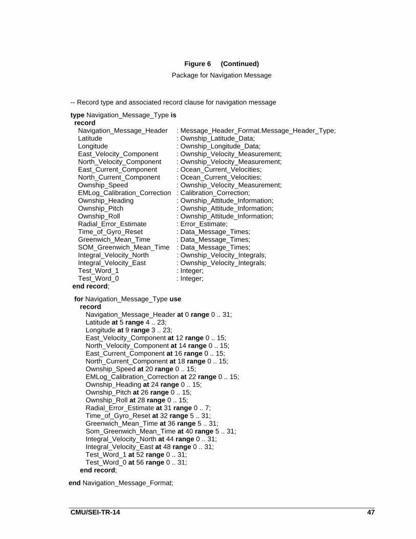
Figure 6
Package for Navigation Message
-- This package contains type definitions for implementing the-- navigation message described in Figure 5
with Message_Header_Format;package Navigation_Message_Format is
-- Deltas used for fixed-point types
CC_Del : constant := 2.0**(-8);DMT_Del : constant := 2.0**(-10);EE_Del : constant := 2.0**(-4);OAI_Del : constant := 2.0**(-15);OCV_Del : constant := 2.0**(-8);OLAD_Del : constant := 2.0**(-6);OLOD_Del : constant := 2.0**(-6);OVM_Del : constant := 2.0**(-8);
-- Fixed-point types for data in the navigation message
type Calibration_Correction is delta CC_Delrange -(8.0 - CC_Del) .. (8.0 - CC_Del);
type Data_Message_Times is delta DMT_Delrange 0.0 .. (86399.0 - DMT_Del);
type Error_Estimate is delta EE_Delrange 0.0 .. (16.0 - EE_Del);
type Ocean_Current_Velocities is delta OCV_Delrange -(11.0 - OCV_Del) .. (11.0 - OCV_Del);
type Ownship_Attitude_Information is delta OAI_Delrange 0.0 .. (1.0 - OAI_Del);
type Ownship_Latitude_Data is delta OLAD_Delrange -5400.0 .. 5400.0;
type Ownship_Longitude_Data is delta OLOD_Delrange -10800.0 .. 10800.0;
type Ownship_Velocity_Integrals is digits 3range -(0.001*(2.0**30 - 1.0)) .. (0.001*(2.0**30 - 1.0))
type Ownship_Velocity_Measurement is delta OVM_Delrange -(128.0 - OVM_Del) .. (128.0 - OVM_Del);
CMU/SEI-TR-14 47
Figure 6 (Continued)
Package for Navigation Message
-- Record type and associated record clause for navigation message
type Navigation_Message_Type isrecordNavigation_Message_Header : Message_Header_Format.Message_Header_Type;Latitude : Ownship_Latitude_Data;Longitude : Ownship_Longitude_Data;East_Velocity_Component : Ownship_Velocity_Measurement;North_Velocity_Component : Ownship_Velocity_Measurement;East_Current_Component : Ocean_Current_Velocities;North_Current_Component : Ocean_Current_Velocities;Ownship_Speed : Ownship_Velocity_Measurement;EMLog_Calibration_Correction : Calibration_Correction;Ownship_Heading : Ownship_Attitude_Information;Ownship_Pitch : Ownship_Attitude_Information;Ownship_Roll : Ownship_Attitude_Information;Radial_Error_Estimate : Error_Estimate;Time_of_Gyro_Reset : Data_Message_Times;Greenwich_Mean_Time : Data_Message_Times;SOM_Greenwich_Mean_Time : Data_Message_Times;Integral_Velocity_North : Ownship_Velocity_Integrals;Integral_Velocity_East : Ownship_Velocity_Integrals;Test_Word_1 : Integer;Test_Word_0 : Integer;
end record;
for Navigation_Message_Type userecord
Navigation_Message_Header at 0 range 0 .. 31;Latitude at 5 range 4 .. 23;Longitude at 9 range 3 .. 23;East_Velocity_Component at 12 range 0 .. 15;North_Velocity_Component at 14 range 0 .. 15;East_Current_Component at 16 range 0 .. 15;North_Current_Component at 18 range 0 .. 15;Ownship_Speed at 20 range 0 .. 15;EMLog_Calibration_Correction at 22 range 0 .. 15;Ownship_Heading at 24 range 0 .. 15;Ownship_Pitch at 26 range 0 .. 15;Ownship_Roll at 28 range 0 .. 15;Radial_Error_Estimate at 31 range 0 .. 7;Time_of_Gyro_Reset at 32 range 5 .. 31;Greenwich_Mean_Time at 36 range 5 .. 31;Som_Greenwich_Mean_Time at 40 range 5 .. 31;Integral_Velocity_North at 44 range 0 .. 31;Integral_Velocity_East at 48 range 0 .. 31;Test_Word_1 at 52 range 0 .. 31;Test_Word_0 at 56 range 0 .. 31;
end record;
end Navigation_Message_Format;

48 CMU/SEI-87-TR-14
Figure 7a
Package for Analog Data
-- This package contains type definitions for implementing the 24-bit-- analog value described in Section 5.5 of the text
package Analog_Data_Format is
type Bit_Type is new Boolean;for Bit_Type use (False => 0, True =>1);
type Bit_Value_Type is range 0 .. 1;for Bit_Value_Type’Size use 1;
type Channel_Type is range 0 .. 3;for Channel_Type’Size use 2;
type Data_Array is array(1 .. 11) of Bit_Value_Type;
type Analog_Data_Type isrecord
Channel : Channel_Type;Validity_Bit : Bit_Type;Data_Bits : Data_Array;Sign_Bit : Bit_Value_Type;Secondary_Scale_Multiplier : Bit_Value_Type;Primary_Scale_Multiplier : Bit_Value_Type;Zero_Bit : Bit_Value_Type:= 0;
end record;
for Analog_Data_Type userecord
Channel at 0 range 6 .. 7;Validity_Bit at 0 range 8 .. 8;Data_Bits at 0 range 9 .. 19;Sign_Bit at 0 range 20 .. 20;Secondary_Scale_Multiplier at 0 range 21 .. 21;Primary_Scale_Multiplier at 0 range 22 .. 22;Zero_Bit at 0 range 23 .. 23;
end record;
Heading_Analog_Data: Analog_Data_Type;for Heading_Analog_Data use at 8#101#;
-- this address clause specifies the address-- for object Heading_Analog_Data to be-- 101 base 8
pragma SHARED (Heading_Analog_Data);
Roll_Analog_Data: Analog_Data_Type;for Roll_Analog_Data use at 8#102#;pragma SHARED (Roll_Analog_Data);
Speed_Analog_Data: Analog_Data_Type;for Speed_Analog_Data use at 8#103#;pragma SHARED (Speed_Analog_Data);
end Analog_Data_Format;

CMU/SEI-TR-14 49
Figure 7b
Procedure for Analog Data Conversion
-- Procedure Convert_Data takes the data which are mapped to particular-- addresses and using the specified equation computes the appropriate-- value
with Analog_Data_Format;procedure Convert_Data is
-- type definitions for computed values
type Heading_Type is digits 8 range 0.0 .. 360.0;type Roll_Type is digits 8 range 0.0 .. 180.0;type Speed_Type is digits 8 range 0.0 .. 100.0;
-- object declarations for data
Heading : Heading_Type;Roll : Roll_Type;Speed : Speed_Type;
package ADF renames Analog_Data_Format;
-- functions to perform actual conversions
-- See Figure 7Cfunction Convert_Data_Bits (Source : ADF.Data_Array; Sign : ADF.Bit_Value_Type)
return Float is separate;
-- See Figure 7Dfunction Convert_Heading (Source_Heading : ADF.Analog_Data_Type)
return Heading_Type is separate;
-- See Figure 7Efunction Convert_Roll (Source_Roll : ADF.Analog_Data_Type)
return Roll_Type is separate;
-- See Figure 7Ffunction Convert_Speed (Source_Speed : ADF.Analog_Data_Type)
return Speed_Type is separate;

50 CMU/SEI-87-TR-14
Figure 7b (Continued)
Procedure for Analog Data Conversion
begin -- Convert_Data
-- Validity check on analog data is performed prior to attempting-- any conversion
-- convert heading dataif ADF.Heading_Analog_Data.Validity_Bit = True then
Heading := Convert_Heading (ADF.Heading_Analog_Data);else
-- raise Invalid_Heading_Data;end if;
-- convert roll dataif ADF.Roll_Analog_Data.Validity_Bit = True then
Roll := Convert_Roll (ADF.Roll_Analog_Data);else
-- raise Invalid_Roll_Data;end if;
-- convert speed dataif ADF.Speed_Analog_Data.Validity_Bit = True then
Speed := Convert_Speed (ADF.Speed_Analog_Data);else
-- raise Invalid_Speed_Data;end if;
end Convert_Data;

CMU/SEI-TR-14 51
Figure 7c
Common Data Bits Conversion Function
-- This function converts the data bits found in the analog data-- This conversion is common in all three conversion equations
with Float_Math_Lib;separate (Convert_Data)function Convert_Data_Bits (Source : ADF.Data_Array; Sign : ADF.Bit_Value_Type)
return Float is
Exponent : Integer range -11 .. 0 := -11;Result_Sign : Float;Temporary : Float := 0.0;
begin -- Convert_Data_Bits
-- loop to compute the argument for the Arctan function callfor Index in Source’Range loop
Temporary := Temporary + (2.0**Exponent)*Float(Source(Index));Exponent := Exponent + 1;
end loop;
Result_Sign := (-1.0)**Float(Sign);
return ( Result_Sign * Float_Math_Lib.ATanD(Temporary));
end Convert_Data_Bits;

52 CMU/SEI-87-TR-14
Figure 7d
Function to Convert Heading Data
-- This function takes heading analog data as a parameter and returns-- a specific heading value
separate (Convert_Data)function Convert_Heading (Source_Heading : ADF.Analog_Data_Type)
return Heading_Type is
Temporary : Float;
begin -- Convert_Heading
-- convert data bitsTemporary := Convert_Data_Bits (Source_Heading.Data_Bits,
Source_Heading.Sign_Bit);
-- computed value returned corresponds to equation found in textreturn (Heading_Type(
180.0*Float(Source_Heading.Primary_Scale_Multiplier)+ 90.0*Float(Source_Heading.Secondary_Scale_Multiplier)+ Temporary));
end Convert_Heading;

CMU/SEI-TR-14 53
Figure 7e
Function to Convert Roll Data
-- This function takes roll analog data as a parameter and returns-- a specific roll value
separate (Convert_Data)function Convert_Roll (Source_Roll : ADF.Analog_Data_Type)
return Roll_type is
Temporary : Float;
begin -- Convert_Roll
-- convert data bitsTemporary := Convert_Data_Bits (Source_Roll.Data_Bits,
Source_Roll.Sign_Bit);
-- computed value returned corresponds to equation found in textreturn (Roll_Type(90.0*Float(Source_Roll.Primary_Scale_Multiplier)
+ 45.0*Float(Source_Roll.Secondary_Scale_Multiplier)+ 0.5*Temporary));
end Convert_Roll;

54 CMU/SEI-87-TR-14
Figure 7f
Function to Convert Speed Data
-- This function takes speed analog data as a parameter and returns-- a specific speed value
separate (Convert_Data)function Convert_Speed (Source_Speed : ADF.Analog_Data_Type)
return Speed_Type is
Temporary : Float;
begin -- Convert_Speed
-- convert data bitsTemporary := Convert_Data_Bits (Source_Speed.Data_Bits,
Source_Speed.Sign_Bit);
-- computed value returned corresponds to equation found in textreturn (Speed_Type ((5.0/18.0)*
(180.0*Float(Source_Speed.Primary_Scale_Multiplier)+ 90.0*Float(Source_Speed.Secondary_Scale_Multiplier)+ Temporary)));
end Convert_Speed;

CMU/SEI-TR-14 55
Figure 8
Checksum Function for Navigation Message
-- Function CheckSum takes a parameter of type Navigation_Message_Type-- and returns the integer checksum of the message
with Unchecked_Conversion;function CheckSum (Navigation_Message : Navigation_Message_Type)
return Integer is
-- type definitions for representing the message as-- an array of 16 bit fieldstype Field_Type is range -32768 .. 32767;for Field_Type’Size use 16;
type Array_of_Fields is array (0 .. 29) of Field_Type;
-- instantiation that will result in the specific unchecked conversion-- function that will take a bit pattern of type Navigation_Message_Type-- and view it as a bit pattern of type Array_of_Fieldsfunction Convert_to_Fields is new Unchecked_Conversion
(Navigation_Message_Type, Array_of_Fields);
CheckSum_Message : Array_of_Fields;Sum : Integer := 0;-- requirements state the sum is to be-- computed as a 32 bit integer
begin
-- perform unchecked conversionCheckSum_Message := Convert_to_Fields(Navigation_Message);
-- compute and return the sum of the fieldsfor I in Array_of_Fields’Range loop
Sum := Sum + Integer (CheckSum_Message(I));
end loop;
return Sum;
end CheckSum;

56 CMU/SEI-87-TR-14
Figure 9a
Package for Gyro Status Types
-- This package contains the type declarations for representing-- data about the status of an inertial navigation system gyro
package Gyro_Status is
type Alignment_Mode_Type is range 1 .. 12;type Bits_to_Left_Type is range 0 .. 16;type Bits_to_Right_Type is range 0 .. 15;type Long_Data_Type is range -(2**31) .. (2**31)-1;type Medium_Data_Type is range -(2**23) .. (2**23)-1;type Short_Data_Type is range -(2**15) .. (2**15)-1;type Status_Type is range 0 .. 1;type Temperature_Type is range 0 .. 100;
type INS_Gyro_Data_Type isrecord
Gyro_Alignment_Mode : Alignment_Mode_Type;M : Bits_to_Left_Type;N : Bits_to_Right_Type;
Gyro_Temperature : Temperature_Type;X_Gyro_Torque : Short_Data_Type;Y_Gyro_Torque : Medium_Data_Type;Z_Gyro_Torque : Long_Data_Type;A_D_Converter : Status_Type;A_D_Multiplexer : Status_Type;RAM_BIT : Status_Type;Gyro_Power : Status_Type;Velocity_Buffer : Status_Type;
end record;pragma PACK(INS_Gyro_Data_Type);
-- this is the type that the torque values must be converted totype Long_Fixed_Type is delta 2.0**(-15)
range -(2.0**16) .. (2.0**16)-1.0;
end Gyro_Status;

CMU/SEI-TR-14 57
Figure 9b
Package for Assembler Conversion
-- This package contains a function specification for an assembler-- routine used in converting gyro torque values to a fixed-point type
with Gyro_Status;with System;package Asem_Convert is
function Asem_Convert_Fixed (Component : System.Address;First_Bit_Offset : Integer;Length : Integer;Left : Gyro_Status.Bits_to_Left_Type;Right : Gyro_Status.Bits_to_Right_Type)
return Long_Fixed_Type;
private
pragma INTERFACE (Assembler, Asem_Convert_Fixed);
end Asem_Convert;

58 CMU/SEI-87-TR-14
Figure 9c
Procedure for Data Encoding of Gyro Status Data
-- This procedure converts the torque values given in the parameter-- to a fixed-point type using an assembler routine
with Asem_Convert;with Gyro_Status; use Gyro_Status;with System;procedure Encode_Data (System_Gyro_Data : in INS_Gyro_Data_Type;
Fixed_X_Gyro : out Long_Fixed_Type;Fixed_Y_Gyro : out Long_Fixed_Type;Fixed_Z_Gyro : out Long_Fixed_Type) is
Addr : System.Address;Length : Integer;Offset : Integer;
package AC renames Asem_Convert;
begin
-- convert x-component of gyro torqueAddr := System_Gyro_Data.X_Gyro_Torque’Address;Offset := System_Gyro_Data.X_Gyro_Torque’First_Bit;Length := System_Gyro_Data.X_Gyro_Torque’Last_Bit - Offset + 1;
Fixed_X_Gyro := AC.Asem_Convert_Fixed (Addr, Offset, Length,System_Gyro_Data.M, System_Gyro_Data.N);
-- convert y-component of gyro torqueAddr := System_Gyro_Data.Y_Gyro_Torque’Address;Offset := System_Gyro_Data.Y_Gyro_Torque’First_Bit;Length := System_Gyro_Data.Y_Gyro_Torque’Last_Bit - Offset + 1;
Fixed_Y_Gyro := AC.Asem_Convert_Fixed (Addr, Offset, Length,System_Gyro_Data.M, System_Gyro_Data.N);
-- convert z-component of gyro torqueAddr := System_Gyro_Data.Z_Gyro_Torque’Address;Offset := System_Gyro_Data.Z_Gyro_Torque’First_Bit;Length := System_Gyro_Data.Z_Gyro_Torque’Last_Bit - Offset + 1;
Fixed_Z_Gyro := AC.Asem_Convert_Fixed (Addr, Offset, Length,System_Gyro_Data.M, System_Gyro_Data.N);
end Encode_Data;

CMU/SEI-TR-14 i
Table of Contents
1. Introduction 1
2. The Problem Domain 3
3. Discussion of Representation Clauses and Implementation-Dependent 5Features in Ada3.1. Introduction 53.2. Pragmas Pack, Optimize, and Shared 63.3. Type Representation Clauses 7
3.3.1. Length Clauses 73.3.2. Enumeration Representation Clauses 83.3.3. Record Representation Clauses 9
3.4. Address Clauses 113.5. Representation Attributes 113.6. Compiler Support 12
4. A Basic Design Model 154.1. Introduction 154.2. Data Abstraction 154.3. Affecting Multiple Representations 164.4. Unchecked Conversion 17
5. Examples 195.1. Introduction 195.2. An Introductory Example 195.3. An Example of Integer Types 205.4. An Example of Fixed-Point and Floating-Point Types 205.5. An Example of Analog Conversion 215.6. Calculation of Message Checksums 24
6. The Use of Assembler Language 276.1. Introduction 276.2. Discussion: Pragma Interface 276.3. An Example 27
7. Guidelines for Design 317.1. Introduction 317.2. System Requirements 317.3. Implementation Plan 317.4. Knowledge of the Compiler To Be Used 327.5. Interfacing Code Developed on Different Compilers 327.6. Grouping Implementation Dependencies Together 327.7. Using Numeric Values in Length and Record Representation Clauses 33

ii CMU/SEI-87-TR-14
7.8. Pragma Storage_Unit 337.9. Referencing Storage 337.10. Run-Time Issues 347.11. Use of Different Compilers in Development 347.12. Knowledge of Support Facilities 34
8. Summary 35
References 37
Appendix I: Figures 39