the user manual for the series of sz05 zigbee embedded module product manual.pdf · the pin of sz05...
TRANSCRIPT

The user manual for the series of SZ05
ZigBee Embedded Module
www.shuncom.com

·2·
The user manual for the series of SZ05 ZigBee Embedded Module
1. Overviews of the SZ05 ZigBee Modules.........................................................................31.1 Appearance...........................................................................................................3 1.2 Key features....................................................................................................................................4 1.3 Specifications...................................................................................................................................41.4 Technical parameters......................................................................................................................41.5 Dimensions......................................................................................................................................5
2. Interfaces.........................................................................................................................................82.1 Module mechanical diagram...........................................................................................................82.2 Left pin ............................................................................................................................................82.3 Right pin........................................................................................................................................92.4 Data interface...............................................................................................................................9
3. Accessories...................................................................................................................................103.1 Antennas.......................................................................................................................................103.2 Evaluation Board and the Converter Board.................................................................................10
4. 4. Configuration.....................................................................................................114.1 Connecting to the computer..........................................................................................................114.2 Entering into computer hyper terminal........................................................................................114.3 Configuration parameter..............................................................................................................12
5. Frequently-used configuration.........................................................................................155.1 The tips for the configuration...................................................................................................155.2 Several typical configuration methods........................................................................................15 (1) Transparent transmission......................................................................................................15 (2) Destination address transmission.........................................................................................15
6. Running description...............................................................................................................156.1 How to connect the device...........................................................................................................15 6.2 Fault description.................................................................................................................16
7. Notes................................................................................................................................................16
8. Technical support.....................................................................................................................16
Contents

·3·
The user manual for the series of SZ05 ZigBee Embedded Module
1. Overviews of the SZ05 ZigBee ModulesShuncom the series of SZ05 ZigBee Embedded Wireless Serial Communication Module, using the ZigBee wireless technical, is compliance with the industrial standards. It has advantages of long communication distance, strong anti-jamming, flexible network to make sure transparent data transmission among many devices with self-organizing star, line and mesh network topology.Shuncom SZ05 ZigBee Wireless Module had been widely applied in industry wireless monitoring communication, such as wireless sensor data acquisition, smart home, IOT, wireless streetlight control, smart grid, wireless automatic meter reading, wireless automatic traffic.
1.1 Appearance
SZ05-L Converter Board
SZ05-ADV-PCBSZ05-STD-PCB
SZ05-L-STD
SZ05-ADV-SMASZ05-STD-SMA
SZ05-L-PRO ZigBee Evaluation Board

·4·
The user manual for the series of SZ05 ZigBee Embedded Module
1.2 Key features
Communication: serial ports of RS232, RS485, TTL convert to ZigBee for wireless communication.Strong wireless features: support Multi hopLong distance: 2000m at sightStrong anti-jamming: ISM (Industrial, Scientific & Medical) 2.4G DSSS Flexible serial port application: transparent format or instruction format transmission, maximal baud rate can be115200Transmit mode: broadcast or destination address transmission to send data can be selectedNode type: coordinator node, router node or end device can be setStrong self-organizing network: star, tree, line or mesh Channels: 16 Direct Sequence Channels. 65535 PAN ID to be selected
1.3 Specifications
SZ05 -xxx -xxx -x -x
Module Distance Interface Plug-in type Supply voltage
SZ05-STD (200 m)-PRO (800 m)-ADV (2000m)
232485TTL
-Z(double pin header )-X(cable) 5V
Such as: The module of SZ05-ADV-485-Z means the series of SZ05 Wireless Data Module, transmission distance 2000m at sight, RS485 interface, double pin header.
Name Notes SZ05 ZigBee Module
Wireless network
Distance(at sight range)SZ05-STD(200 M)SZ05-PRO(800 M)SZ05-ADV(2000M)
Network topology Star, tree, link and mesh
Addressing option IEEE802.15.4/ZIGBEE standard address
Net ID 00-FF
Data interfaceThe maximal data packet 100 bytes
Data interface RS232, RS485 or TTL
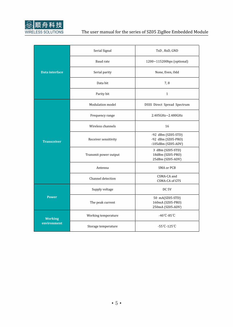
1.4 Technical parameters
·5·
The user manual for the series of SZ05 ZigBee Embedded Module
Data interface
Serial Signal TxD , RxD, GND
Baud rate 1200~115200bps (optional)
Serial parity None, Even, Odd
Data bit 7, 8
Parity bit 1
Transceiver
Modulation model DSSS Direct Spread Spectrum
Frequency range 2.405GHz~2.480GHz
Wireless channels 16
Receiver sensitivity-92 dBm (SZ05-STD)-92 dBm (SZ05-PRO)-105dBm (SZ05-ADV)
Transmit power output3 dBm (SZ05-STD) 18dBm (SZ05-PRO) 25dBm (SZ05-ADV)
Antenna SMA or PCB
Channel detection CSMA-CA and CSMA-CA of GTS
Power
Supply voltage DC 5V
The peak current50 mA(SZ05-STD)
160mA (SZ05-PRO)250mA (SZ05-ADV)
Working environment
Working temperature -40℃-85℃
Storage temperature -55℃-125℃

·6·
The user manual for the series of SZ05 ZigBee Embedded Module
1.5 Dimensions
SZ05 Standard Modules contain SZ05-STD, SZ05-PRO and SZ05-ADVSZ05- L Small Modules include SZ05-L-STD and SZ05-L-PRO(1) SZ05 Standard Module dimensions:
14.4mm
22.3mm
21.9mm
27.3mm
The Size of SZ05 Standard Module
2.4m
m
8.6m
m
2.6m
m
3.0m
m2.
5mm
47.5mm
42.5mm
6.5mm
2.5mm
0.9mm
2.7mm
2.5mm
Φ
2.7mm

·7·
The user manual for the series of SZ05 ZigBee Embedded Module
(2) SZ05-L Small Module dimensions:
17.00mm
15.00mmIO 1 IO 3
IO 4
IO 5
IO 6
IO 7
GND
VCC
RX 1
TX 1
SND
TX 2
RX 2
MS
RST
UCC
GND
IO 8
IO 9
IO 2
AD 1
AD 2
AD 3
AD 4
RUN
NET
CFG
GND
IO 5
ALM
SLD
C485
The Size of SZ05-L Small Module
28.0
0mm
21.5
0mm

·8·
The user manual for the series of SZ05 ZigBee Embedded Module
2. Interfaces2.1 Module mechanical diagramShuncom SZ05 ZigBee Module has interfaces of RS232, RS485 and TTL which are vey convenience for equipment connection. Pin connection as follows:
2.2 Left pin
Pin number Pin name Functions Notes
5 AD4
6 RUN Run LED
7 NET Net LED
8 ALM Alarm LED
9 SLP Sleep Low level effective
A
B I08 Reserved for IO
C I09 Reserved for IO
D CFG Configuration control Low level effective
SMA
3.3V1K LED AD4 GND
Sleep control (low level effective)
The Pin of SZ05 ZigBee Module
RS485 receiver control
Reserve IO
Reserve IO
Configuration control
GND
The anode of power, 5V
The GND of RS232
Reserve
Reset (low level effective)
TTL level, connecting to TX of user
TTL level, connecting to RX of user
RS232/485, connecting to RX of user
RS232/485, connecting to TX of user
RNURNU VCC
NETNET RS1
ALMALM TX1
CFG RET
SLP SGND
TX2
IO8 RX2
IO9

·9·
The user manual for the series of SZ05 ZigBee Embedded Module
2.3 Right pin
Pin number Pin name Functions Notes
15 GND The anode of power
16 VCC The cathode of power 5V
17 RX1 TTL Links to the TX of user
18 TX1 TTL Links to the RX of user
19 SGND The GND of RS232
1A TX2 RS232/RS485 Connects RX/A of user
1B RX2 RS232/RS485 Connects RX/B of user
1C Reserved Reserved
1D RST Reset Low level effective
Normally, the required pin connections are VCC, GND, TTL, RS232 or RS485. All unused pins should be left disconnected
2.4 Data interface
SZ05-ZigBee Wireless Module has standard interface of RS232, RS485 or TTL in the hardware. Serial RS232 includes TX2, RX2 and GND. RS485 contains TX2(A+), RX2(B-). TTL interface is TX1 and RX1, and the level of TTL is 3.3V.
Notes:RS232 and RS485 cannot be used at the same time. It is required to be sure that which one interface you want to use when you make the buying .

·10·
The user manual for the series of SZ05 ZigBee Embedded Module
Frequency band: 2.4G Gain:5dBistanding wave:《 1.5interface: SMA maleLong glue stick antenna: length 21CMShort glue stick antenna: length 11CM
Glue stick antenna Suction cup antenna
The extended cableFiberglass antenna
Frequency band: 2.4GGain: 8dBiStanding wave:《1.5Interface: SMA male
Application: to convenient to extend the antenna out of the box.Frequency band: 2.4GLength: 1M, 2M, 3M (optional )
Frequency band:2.4G Gain: 1dBiStanding wave:《 1.5Interface: SMA male
3. Accessories3.1 Antenna
Operating frequency baud: ISM 2.4GHz, 2405M—2485MInterface type: SMA maleAntenna type: Glue stick antenna, Suction cup antenna, Fiberglass antennaAntenna attachment: the extended cable
3.2 Evaluation Board and SZ05-L Converter Board
Shuncom SZ05 ZigBee Evaluation Board is for Standard Module to configurate parameters. And the SZ05-L Converter Board is convenient for the SZ05-L Small Module to mount into the SZ05 ZigBee Evaluation Board.
Notes: The extended cable and the suction cup antenna should not be more than 3 meters. The suitable length is within 1m. Because the longer cable length, the shorter transmission distance you will get
ZigBee Evaluation BoardSZ05-L Converter Board
SZ05-L Small Module Mounting to the SZ05-L Converter Board (Called SZ05-L System)
SZ05-L System Mounting to the SZ05 Evaluation Board
SZ05-L Small Module
SZ05 Mounting to the ZigBee Evaluation Board
SZ05 Standard Module

·11·
The user manual for the series of SZ05 ZigBee Embedded Module
(1) ZigBee Evaluation Board
(2) SZ05-L Converter Board
ZigBee Evaluation Board Parameters
Specification Zigbee Evaluation Board
Applicable module SZ05 Standard Module
Voltage DC5V~24V
Data interface RS232, RS485 or USB
Function descriptionConvenience for user to configurate module; to prevent burning out module in case of wrong wiring connection
ZigBee Converter Board Parameters
Specification SZ05-L Converte Board
Applicable module SZ05-L Small Module
Power supply DC3.7V~5V
Data interfaceConvenience for user to configurate module; to prevent burning out module in case of wrong wire connection
Others Recommend to use with SZ05 ZigBee Evaluation Board
4. Configuration4.1 Connecting to the computer
SZ05 ZigBee Module mounting into the ZigBee Evaluation Board, then connect the ZigBee Evaluation Board to computer.
4.2 Entering into the computer hyper terminal.
1. Open the computer hyper terminal (Star→ Programs→Accessories→Communications→Hyper Terminal.) choose right serial port and the configuration is:
Baud rate: 38400, Data Bit: 8, parity: NONE, Stop Bit: 1, Flow: NONE2. Power on.3. Press “CFG” for 3 seconds.4. Alarm light and run light flash at the same time5. Module is on configuration mode.

·12·
The user manual for the series of SZ05 ZigBee Embedded Module
4.3 Configuration parameters
1). Address setting
2). Node type setting
3). Network
4).Network ID setting
5). Channel setting
Name ID configuration Notes
MAC_Addr 0000-FFFEIt cannot have the same a d d re s s w i t h i n t h e same network.
the coordinator address must be 0000
Notes: every ZigBee Module has the unique MAC_Address, it is not allowed to share the same address within the same network. We use two bytes to define the MAC address.
Notes: In the same network, the Net_ type must be the same.
Node Name Description
PAN_Coord It is the coordinator which can select a channel and PAN ID to start the network.
Router Not only assist in routing data but also having the functions of end_device.
End_Device Only send data of itself and receive data from the router and coordinator.
NET_ID Notes
PAN_Coord The NET_ID must be set to be same in the same network
Net_Type Notes
MeshMesh, star and line networks are the master-slave networks. They must have a coordinator. All modules within the same network must set the same type of network.
Star
Line
Peer Peer to peer type network does not need coordinator.
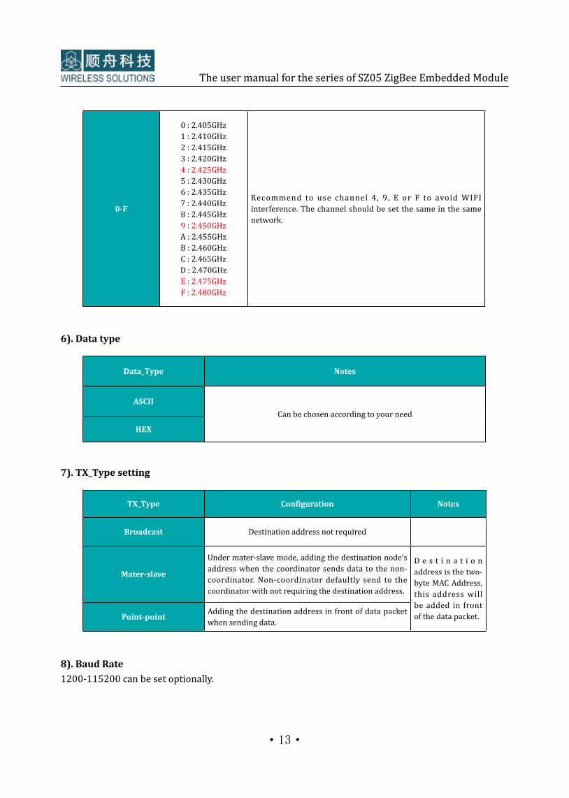
Frequency Channels Notes
·13·
The user manual for the series of SZ05 ZigBee Embedded Module
0-F
0 : 2.405GHz 1 : 2.410GHz 2 : 2.415GHz 3 : 2.420GHz 4 : 2.425GHz 5 : 2.430GHz 6 : 2.435GHz 7 : 2.440GHz 8 : 2.445GHz 9 : 2.450GHz A : 2.455GHz B : 2.460GHz C : 2.465GHz D : 2.470GHz E : 2.475GHz F : 2.480GHz
Recommend to use channel 4, 9, E or F to avoid WIFI interference. The channel should be set the same in the same network.
6). Data type
7). TX_Type setting
Data_Type Notes
ASCIICan be chosen according to your need
HEX
TX_Type Configuration Notes
Broadcast Destination address not required
Mater-slave
Under mater-slave mode, adding the destination node’s address when the coordinator sends data to the non-coordinator. Non-coordinator defaultly send to the coordinator with not requiring the destination address.
D e s t i n a t i o n address is the two-byte MAC Address, this address will be added in front of the data packet.Point-point Adding the destination address in front of data packet
when sending data.
8). Baud Rate1200-115200 can be set optionally.

·14·
The user manual for the series of SZ05 ZigBee Embedded Module
9). Data Parity setting
10). Data Bit Setting
11). Data source address
12). Default settings
Data_Parity Notes
None
According to your requirement to choose the suitable parity.Even
Odd
Data Bit(data bit +parity +stop bit) Notes
7+1+1
Choose the data bit setting based on the selection of data parity setting.8+0+1
8+1+1
8+0+2
Src_Add Notes
Not output
Generally, default setting" No Output".HEX
ASCII
Notes: The module will be out of the configuration mode when there is no more operation within 60 seconds. All the settings will stay unchanged.

·15·
The user manual for the series of SZ05 ZigBee Embedded Module
5. Frequently-used configuration5.1 The tips for the configuration(1).The coordinator’s address is 0000.The address of the non-coordinators (router and end_device) can be set optionally from 0001 to FFFE, but the routers’ addresses must be different in the same network, or else they cannot communicate.(2). Each network is defined with a unique channel and PAN ID. The channel and the PAN ID must be the same in the unique network. And the baud rate, parity, data bit should be consistent with the connected devices.
5.2 Several typical configuration methods1) Transparent transmissionThe coordinator is set as broadcast, and the router or end_device are set as Master-slave or broadcast (Other parameters please refer to Page 14 configuration).2) Destination address transmission① Mater-slave modeThe coordinator, router and end_devicea are set as master-slave mode (Other parameters please refer to Page 14 configuration).It is required to add destination address when the coordinator sends data to the non-coordinators.Non-coordinators defaultly sent to the coordinator with not requiring destination address.② Point-point modeIn this mode, only two devices are allowed to communicate. Add the destination address in front of data packet when sending data.
6. Running description6.1 How to connect the modules(1) It will need to connect to PC when SZ05 is set to be coordinator.(2) If SZ05 used as router, it only requires DC power supply then data will be transmitted.(3) The end_devices connect to user devices. (The end_device also can be set as the router which not only can transmit the data of itself but also have the router functions.)
PC SZ02 Coordinatorzigbee wireless communication
Zigbee wireless communicationSZ05 end_device mounting into the end user device by the RS232, RS485 or TTL
SZ05Router
SZ05 end_deviceEnd user device
232/USB/Net interface connection by wiring

·16·
The user manual for the series of SZ05 ZigBee Embedded Module
6.2 Fault description
7. Notes (1) Power supply is DC5V(2) Module is not waterproof and not lightning protection.(3) The anode and cathode of power do not reversed, otherwise it will burn out the module(4) Module should be installed in anti- static environment , the antenna should be kept away from the metal objects
8. Technical supportShanghai Shuncom Electronic Technology Co.,LtdAdd: 4-502 No.289. Bisheng Road , Zhangjiang High-Tech Park, Shanghai, China Tel: +86-021-33933988/78/68/58/28/18Fax: +86-021-33933988-6800Email: [email protected], [email protected] Http: www.shuncom.com
Symptom Solution to the problem
Module too hot ,current too strong Maybe module burn out ,please connect suppliers to check it
Short transmission distance Check whether there is damage to the antenna, having obstacles will also cause the shorter distance.
Cannot connect to the equipment to communication
Module interface choosing is correct or not. Confirm whether configuration parameters are consistent with the connected devices.
Module cannot communication Make sure that configuration parameters are consistent with the connected devices.