the ussher society 2, part 5, 1972.pdf · the ussher society exists to promote research into all...
TRANSCRIPT

THE USSHER SOCIETY
Chairman Prof. D. L. Dineley
Vice-Chairman Mr. F. W. Sherrell
Secretary Dr. S. C. Matthews
Treasurer Dr. P. A. Floyd
Editor Dr. E. B. Selwood
Committee members : Mr. K. E. Beer Mr. C. M. Bristow Dr. J. W. Inglis Prof. C. Kidson Dr. C. T. Scrutton
Membership of the Ussher Society is open to all on written application to the Secretary and payment of the annual subscription (£1.50 ordinary members, £1.00 students and retired members) due on January lst each year. Cheques should be made payable to the Ussher Society.
Back numbers may be purchased, post free, from the Secretary at the following rates :
Volume 1 (Parts 1-6) 75p (38p Members). Volume 2 (Parts 1-3) 75p (38p Members). Volume 2 (Part 4) £1.50 (£1 Members). Bristol Abstracts (1960) 38p.
Correspondence and requests for membership and publications should be addressed to :
Dr. S. C. Matthews, Department of Geology,
Queen's Building, University Walk
Bristol. BS8 1TR.


PROCEEDINGS
OF THE
USSHER SOCIETY
VOLUME TWO PART FIVE
_______________
Edited by E. B. SELWOOD _______________
REDRUTH, NOVEMBER 1972

PROCEEDINGS
OF THE
USSHER SOCIETY
VOLUME TWO PART FIVE
_______________
Edited by E. B. SELWOOD _______________
REDRUTH, NOVEMBER 1972
PRICE: £1.50

CONTENTS
page CHAIRMAN'S REPORT ... ... ... 355
SYMPOSIUM. Some aspects of Engineering Geology in South West England
Chairman's Introduction ... ... ... 356
Engineering geology in reservoir construction in South West England. By J. L. Knill. ... ... ... 359
The influence of weathering on the layout of quarries in South West England. By W. R. Dearman and P. G. Fookes. ... ... ... ... 372
Some examples of cliff failure in S.W. England. By H. M. de Freitas. ... ... ... ... 388
Geological investigation for a proposed offshore tunnel in the Dodman Point-Maenease Point area. By M. S. Money. ... ... ... ... ... 397
Slope stability problems in the china clay industry of South West England. By M. J. Ripley. ... ... 405
The geological aspects of colliery tipping in South Wales and Somerset (Abstract). By A. N. Lane ... ... 409
The mineralogy and chemistry of axinite reaction veins cutting the Meldon aplite. By D. M. Mackenzie. ... 410
A model for the development of the greenstones and growth of S.W. England. By P. A. Floyd. ... ... 417
Preliminary petrological and geochemical data on the Cudden Point greenstone. By P. A. Floyd and G. J. Lees. ... ... ... ... ... 421
Geochemistry of the Permian igneous rocks of Devon - some conclusions (Abstract). By M. E. Cosgrove. ... 423
Geochemistry and mineralogy of the Permo-Trias of South- West England (Abstract). By M. E. Cosgrove. ... 424
Wall-rock alteration at Geevor Tin Mine. By I. R. Wilson. ... 425
Gypsum in the Perran Iron Lode, Cornwall. By S. Henley. ... 435
Hydraulic fracturing in south Pembrokeshire and north-west Devon (Abstract). By P. L. Hancock. ... ... 437
Oblique folds in South-West England. By D. J. Sanderson. ... 438
The Tertiary structure of the Haldon Hills. By R. J. O. Hamblin. ... ... ... ... 442
The form of the Permo-Triassic basin in south-east Devon. By M. R. Henson. ... ... ... 447
Provincial affinities of Eifelian phacopids (Trilobita) of South West England. By C. J. Burton. ... ... 458
The Upper Carboniferous statigraphy of north Cornwall and west Devon. By E. C. Freshney and R. T. Taylor. ... 464
The conodont biostratigraphy of the Plymouth Limestones about the Middle/Upper Devonian boundary. By M. J. Orchard. ... ... ... ... 471 The following papers were also read :
Invitation address. Marine geology of the region between Brittany and Munster (Eire) - a speculative review. By D. Curry.
Heavy mineral concentrations in the Bladder Wrack (Fucus vesiculosus) of the Bristol Channel. By R. Fuge.
Exe estuary sedimentation. By J. M. Thomas.

CONFERENCE OF THE USSHER SOCIETY HELD AT TORQUAY, JANUARY, 1972
CHAIRMAN'S REPORT
The aims of our Society, to promote research into all aspects of geology, applied geology and geomorphology in the South West, were well realised during this conference, which was held at Torquay. The first day, which was devoted to general geology, commenced with an invited address, presented by Mr. D. Curry ; this was most stimulating. The second day brought what was an innovation to the Society, namely a day given to engineering geology. During this session which was attended by eighty two persons, including members of the Society and some twenty six visiting Civil Engineers from various walks in the South West, a broad spectrum of engineering geology was presented, both by invited speakers and members working in the sphere of engineering geology. The conference marked the tenth anniversary of the Ussher Society, an occasion which was duly celebrated by the holding of a ‘Conference Dinner’ at the conclusion of the formal Conference Programme.
The third day was devoted to field excursions. Following a brief visit to the Beacon Cove area, the excursion was devoted to the Chudleigh By-Pass and to some of the engineering geological problems encountered. This visit gave members an opportunity to examine some of these and other problems associated with motorway construction - and perhaps evidence of the ‘properties of mud’ and its capacity to envelop the unwary during a walk along an engineering site.
The eleventh conference will probably be held in the Weymouth area, and will provide a welcomed opportunity to see and examine some younger rocks in the south west.
Finally on a personal note, I would like to record my sincere thanks to all members of the Society and to the visiting speakers who have helped so much during the past two years of my chairmanship. I am sure that the Society will continue to grow and prosper under the chairmanship of Professor Dineley, who now succeeds me.
F.W. Sherrell

SYMPOSIUM ON SOME ASPECTS OF ENGINEERING GEOLOGY IN SOUTH WEST ENGLAND
CHAIRMAN'S INTRODUCTION The Ussher Society exists to promote research into all aspects of
the geology, applied geology and geomorphology of South West England, and with the discussion and dissemination of that research on the occasion of its annual conference. It is appropriate on this tenth anniversary of the formal constitution of the Society, at a time when major civil engineering works of considerable engineering geological interest are under construction, that this session is to be devoted entirely to engineering geology, con-tributed to by a number of invited speakers, and before an audience which in addition to members of the Society, includes many civil engineers from various walks in the south west.
Before embarking on our programme, it is perhaps encumbent upon me to attempt to define what engineering geology is and briefly to review the history of this branch of science. It represents a different thing to different people. To some it is a hybrid science, coming from the borderland between geology and civil engineering. However, I would suggest that if it is a hybrid, so also is geology itself, for it is difficult to imagine how geology could be what it is, without the aid of physics, chemistry and biology, and assisted by the language of mathematics. The same can be said of civil engineering but perhaps the more so, in view of the broad spectrum of that science.
To appreciate the historical aspects and the growth of engineering geology, it is necessary to consider also the growth of soil mechanics, which many would argue is the older discipline. Although some of the basic principles of geology may have been understood by the ancient philosophers of Greece and Rome, the real study of geology, particularly of stratigraphy, dates from the early part of the last century, the founder being William Smith, the "father of stratigraphy," who was himself a civil engineer. Regretably, with the passing of William Smith and his con-temporaries, the influence of geology upon civil engineering declined, because geology remained an inexact science, lacking quantification. As the 19th century progressed, there developed a "science for its own sake" attitude, which tended to divorce geology from technological application, as suggested by Dr. Dunham in 1970 in his introduction to the Yorkshire Geological

Society's Symposium on ‘The Geological Aspects of Development and Planning in Northern England.’ In defence of this, one must allow that geological science had to grow before it could be applied. Furthermore, engineers had been wrestling with founda-tion problems long before the advent of geological science as we know it to-day. Many of those problems were presented by what in to-day's terminology would be termed engineering soils, rather than in situ rock ; the scope of engineering being such that engineers were and are concerned with relatively shallow depths in a limited area, as compared to the great thickness and area of the earth's crust, which is the domain of the geologist. Even a major reservoir site is still a small one by geological standards. Some progress in the solution of the geotechnical problems encountered in civil engineering was made during what has been termed by Mr. Glossop in his Rankine Lecture to the British Geotechnical Society in 1968 as, ` the early period,' between the end of the 17th century and the beginning of the 20th century. Significant progress was made in civil engineering processes in the latter half of the 19th century, including the use of compressed air, ground freezing, and grouting techniques in construction. In parallel, significant progress was made in engineering design, which led to an increase in the magnitude and degree of sophistication of civil engineering works, encompassing larger and deeper areas of the countryside. With this progress came the realisation that where civil engineering works had sometimes failed, the failure was not so much in the structure itself, but in the geological environment in which that structure was located. Research was accelerated in many European countries in the early part of this century, involving the energies of many talented engineers, culminating with the emergence in the early 1920's of Karl von Terzaghi and with him the age of Classical Soil Mechanics Theory, of which as stated by Mr. Glossop in his Rankine Lecture, "the cornerstone was the concept of Effective Stress"
During the period of emergence of Classical Soil Mechanics, engineers showed a renewed interest in geology. In America, following the St. Francis Dam disaster, the necessity for full geological investigation of reservoir and dam sites became very evident and it became the practice of engineers to seek the advice of geologists. Both in America and elsewhere, a new type of specialist entered the arena - the engineering geologist. To answer the questions raised by engineers it became necessary for

the engineering geologist to obtain more than just a notion of civil engineering and the behaviour of engineering structures ; it also became necessary to have a thorough knowledge of soil mechanics and to attempt to apply such knowledge to the rocks, where the presence of discontinuities added further problems to the employment of soil mechanics which up to that time had been concerned primarily with homogeneous soils. Even in the early days of Classical Soil Mechanics Theory, Terzaghi realised and was at pains to stress that the problems of soil mechanics are basically geological. He stated that the first step in investigation should be the exploration of the geological structure and hydrology of a site, after which the methods of physics should be applied to measure the mechanical properties of the soils and rocks, to provide data for rational design.
Moving forward to the present time, vigorous research con-tinues in soil mechanics and in its allied but younger science, that of rock mechanics, both of which form essential aids to engineering geology. It is not my intention to discuss the nature of these researches, or to become involved in what might be emotive issues as to which is the ‘basic discipline,’ or where the boundaries are to be drawn between these disciplines. As I suggested earlier, engineering geology is a different thing to different people. To me, and this is purely a personal view, it is a separate science in the borderland between geology and engineering, in which geology is interpreted, assessed and quantified, to provide design criteria for the broad spectrum of civil engineering. Its media are geology, together with hydrogeology, geophysics and geochemistry, with the vital assistance of soil and rock mechanics. Collectively it is I believe a science in its own right.
After this most timely session, the subject of which is "Some Aspects of Engineering Geology in South West England," non-engineering geologists and civil engineers may have a clearer understanding of what is engineering geology. Whatever that understanding may be, all of us, whether we may be geologists, geomorphologists, engineers or engineering geologists, will I feel sure be the richer in our knowledge at the end of this session.
F. W. Sherrell, Frederick Sherrell, Consulting Engineering Geologists, Tavistock, Devon.

ENGINEERING GEOLOGY IN RESERVOIR CONSTRUCTION IN SOUTH WEST ENGLAND
by J. L. Knill Abstract. The main engineering problems which arise in the location, design and construction of dams and reservoirs are discussed in relation to the Palaeozoic rocks and granites of South West England.
1. Introduction
The preliminary location of reservoir sites is primarily determined by the hydrological characteristics of the catchment and the topography of the potential reservoir basin. As a second stage, the site geology then becomes of importance particularly with regard to the confirmation of reservoir watertightness and assessment of conditions at the proposed dam site. The review will normally lead to the recognition of a limited number of sites which are both technically feasible and which are not likely to cause unreasonable intrusion into, or damage to, the environment.
In South West England there are special questions which arise in relation to the principle of constructing reservoirs and the factors involved in their location. The region as a whole has a moderate rainfall, concentrated in the winter season, and a major demand for water in the summer arising particularly from the tourist demand. There are few aquifers of significance and it is therefore inevitable that the summer demand can, under present circumstances, only be supplied by storage in reservoirs. The physiography of South West England is, in addition, such that water is best supplied from a series of small reservoirs rather than a single major source. There have been proposals to construct reservoirs for regional water supply schemes, such as was suggested at De Lank on Bodmin Moor. but this proposal was not proceeded with. More recently, major controversy has resulted from the promotion of a Parliamentary Bill to construct a reservoir at Swincombe on Dartmoor to provide an urgent need for water in Devon. The Bill was rejected at the Committee stage in 1971 and further consideration has been given to alternative sites. Regional geology has an influence in this broader issue of reservoir location. The sites on granite are characterised by wild,

lonely landscape of little economic value whereas those on the surrounding country rocks would flood agricultural land of value but less scenic distinction.
More detailed assessment of geology is relevant to the appraisal of reservoir feasibility, and to the factors involved in dam design and construction. The paper reviews these topics in relation to conditions in South West England.
2. Reservoir Feasibility The main geological factor which controls the feasibility of
a reservoir is the watertightness of the basin. The conditions of flow through a rock mass are controlled by the Darcy equation Q = kia, where Q = rate of flow, k = permeability, i = hydraulic gradient and a = area through which flow is taking place. Leakage will not take place from a reservoir where the pre-existing groundwater pressures in the reservoir flank are greater than the pressures imposed by the water contained within the reservoir. It is inevitable that there will be a hydraulic gradient from the reservoir water level to the tailwater downstream of the dam, and so some leakage must occur close to dams. However, it is normal practice to assess the extent of such leakage near the dam and to carry out appropriate engineering measures to reduce and control this leakage. The permeability of the rocks which underlie a reservoir determine in part the rate of leakage. In more massive rocks, such as granite, or shales and slates, the low bulk permeability tends to provide suitable reservoir con-ditions. However, in areas underlain by limestones, faults or old mine workings, localised zones of high permeability could give rise to significant leakage.
Major rock defects have influenced decisions on reservoir location in South West England. A site on the River Hayle, for example, some six miles east of Penzance has been considered but extensive old mine workings are present both within and on the flanks of the reservoir basin. On the northern flank of the site, the workings have resulted in groundwater drainage so that the water table is below the proposed top water level. On the western side, the conditions are more serious in that the reservoir would have flooded a major system of veins associated with the Friendship Lode which has been worked to a depth of about two hundred metres below sea level. A direct leakage path exists,

therefore, from the potential reservoir to a lower topographic level. Another suggested site, on the River Tavy about three km upstream of Marytavy, has been rejected on similar grounds to that on the Hayle. In this case the country rock is composed of metamorphosed dolerites with shales and grits intruded by a series of east-west trending tin lodes (Hillbridge Consols), linked by crosscourses, which outcrop on the western flanks of the proposed reservoir. These veins, which appear to have been worked to a limited degree, join up with the Jewell Mine where lodes have been worked to a depth of about 160m. Some 3 km west of the proposed reservoir margin this lode system meets a north-south lode worked to depths well below O.D. at the Betsy Mine where drainage adits are also present. In this case, the distribution of veins and workings was such that a risk of leakage was acknowledged although the critical groundwater observations do not appear to have been made.
Apart from the localised defects which occur within rock masses and influence reservoir feasibility, the question of water-tightness is closely related to the pre-existing groundwater con-ditions in the reservoir margin (Knill 1972). A good example of this situation is provided by the investigations carried out in connection with the North Devon Pumped Storage Scheme at Cranford, west of Bideford in North Devon. The proposed scheme involved pumping sea water at night from Bideford Bay through a system of tunnels and shafts into the Cranford reservoir with a top water level of 205m above O.D. Electricity would be generated at peak times by releasing water from the reservoir, Water would be returned to the reservoir when base load electricity produced by base load thermal stations was at low cost. A major uncertainty at the site arose in connection with the watertightness of the reservoir basin with regard to sea water. Under normal circumstances, minor seepage from reservoirs is of limited concern but in this case any loss of water from the reservoir would be readily identifiable. The bedrock consists of closely interbedded Culm mudstones and sandstones, which are strongly folded on east-west axes. In consequence, there would be no continuity in any particular layer below the reservoir which might provide a limit to potential downward penetration of saline water. In situ permeability tests were also carried out in boreholes to a depth of 100 m below the reservoir floor. These tests revealed that the

FIGURE 1. Variation in level of water table around margin of proposed Cranford reservoir, illustrated by cross-section around reservoir rim. g.l. - ground level T.W.L. - top water level of reservoir g.w.l. - ground water level Dd - normal drawdown level of reservoir
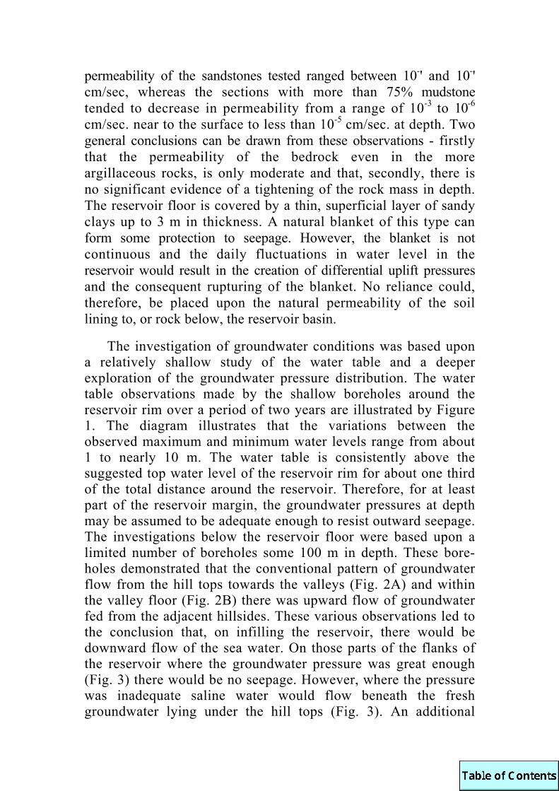
permeability of the sandstones tested ranged between 10-' and 10-' cm/sec, whereas the sections with more than 75% mudstone tended to decrease in permeability from a range of 10-3 to 10-6 cm/sec. near to the surface to less than 10-5 cm/sec. at depth. Two general conclusions can be drawn from these observations - firstly that the permeability of the bedrock even in the more argillaceous rocks, is only moderate and that, secondly, there is no significant evidence of a tightening of the rock mass in depth. The reservoir floor is covered by a thin, superficial layer of sandy clays up to 3 m in thickness. A natural blanket of this type can form some protection to seepage. However, the blanket is not continuous and the daily fluctuations in water level in the reservoir would result in the creation of differential uplift pressures and the consequent rupturing of the blanket. No reliance could, therefore, be placed upon the natural permeability of the soil lining to, or rock below, the reservoir basin.
The investigation of groundwater conditions was based upon a relatively shallow study of the water table and a deeper exploration of the groundwater pressure distribution. The water table observations made by the shallow boreholes around the reservoir rim over a period of two years are illustrated by Figure 1. The diagram illustrates that the variations between the observed maximum and minimum water levels range from about 1 to nearly 10 m. The water table is consistently above the suggested top water level of the reservoir rim for about one third of the total distance around the reservoir. Therefore, for at least part of the reservoir margin, the groundwater pressures at depth may be assumed to be adequate enough to resist outward seepage. The investigations below the reservoir floor were based upon a limited number of boreholes some 100 m in depth. These bore-holes demonstrated that the conventional pattern of groundwater flow from the hill tops towards the valleys (Fig. 2A) and within the valley floor (Fig. 2B) there was upward flow of groundwater fed from the adjacent hillsides. These various observations led to the conclusion that, on infilling the reservoir, there would be downward flow of the sea water. On those parts of the flanks of the reservoir where the groundwater pressure was great enough (Fig. 3) there would be no seepage. However, where the pressure was inadequate saline water would flow beneath the fresh groundwater lying under the hill tops (Fig. 3). An additional
factor exists in that the density of the saline water would be in excess of that of the fresh groundwater, so a relatively higher column of fresh water would be required to balance seepage than in the more usual case. Various measures could have been adopted to prevent, reduce, or control seepage as appropriate ; these include blanketting, cutoffs, grouting, artificial supplementation of the natural groundwater pressures and drainage.
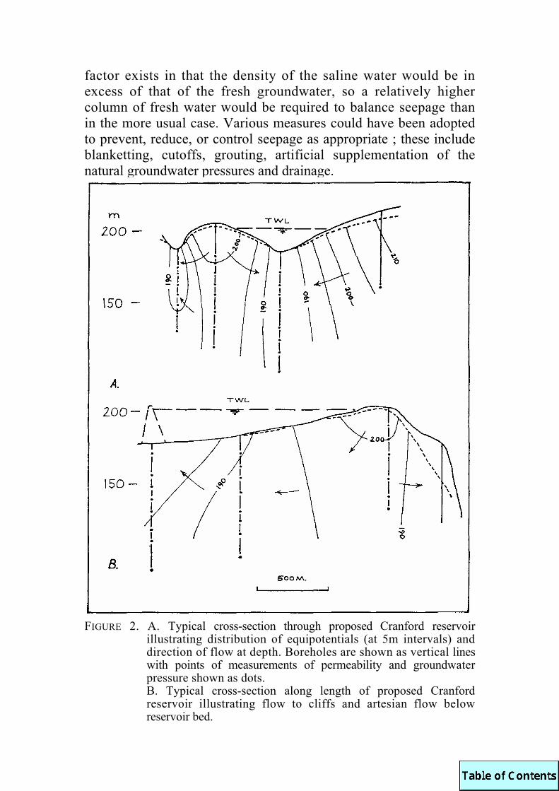
FIGURE 2. A. Typical cross-section through proposed Cranford reservoir
illustrating distribution of equipotentials (at 5m intervals) and direction of flow at depth. Boreholes are shown as vertical lines with points of measurements of permeability and groundwater pressure shown as dots. B. Typical cross-section along length of proposed Cranford reservoir illustrating flow to cliffs and artesian flow below reservoir bed.
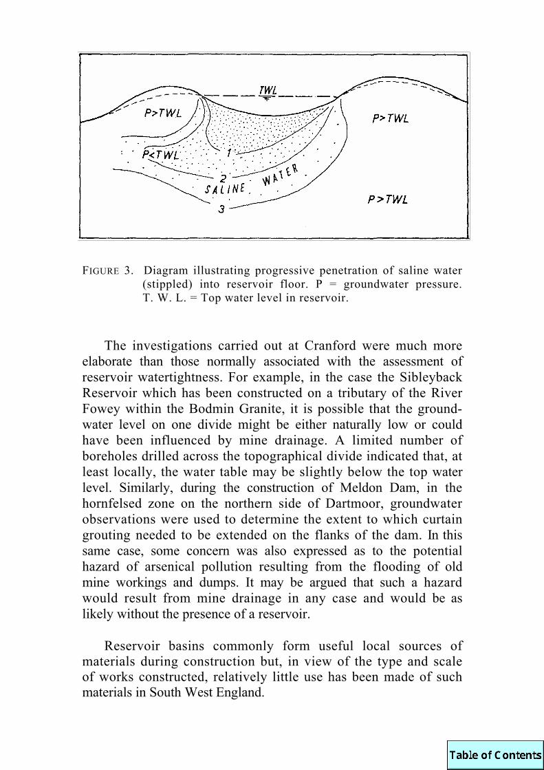
FIGURE 3. Diagram illustrating progressive penetration of saline water
(stippled) into reservoir floor. P = groundwater pressure. T. W. L. = Top water level in reservoir.
The investigations carried out at Cranford were much more elaborate than those normally associated with the assessment of reservoir watertightness. For example, in the case the Sibleyback Reservoir which has been constructed on a tributary of the River Fowey within the Bodmin Granite, it is possible that the ground-water level on one divide might be either naturally low or could have been influenced by mine drainage. A limited number of boreholes drilled across the topographical divide indicated that, at least locally, the water table may be slightly below the top water level. Similarly, during the construction of Meldon Dam, in the hornfelsed zone on the northern side of Dartmoor, groundwater observations were used to determine the extent to which curtain grouting needed to be extended on the flanks of the dam. In this same case, some concern was also expressed as to the potential hazard of arsenical pollution resulting from the flooding of old mine workings and dumps. It may be argued that such a hazard would result from mine drainage in any case and would be as likely without the presence of a reservoir.
Reservoir basins commonly form useful local sources of materials during construction but, in view of the type and scale of works constructed, relatively little use has been made of such materials in South West England.

3. Dam Construction The preliminary location of a dam is frequently based upon
selection of a site involving a minimum volume, and so minimum cost of the structure. The prime requirements for a dam foundation are that it should (a) carry the vertical loads and shear stresses imposed by the weight of the dam, (b) be of sufficient imperme-ability to keep seepage to a minimum and, in the case of concrete dams, (c) be rigid enough to ensure that excessive deformation does not result.
The criterion of deformability is of considerable importance in the case of concrete dams. The main geological requirements are that the depth of overburden and weathered rock should be limited and so the depth of excavation to sound rock, suitable for the dam foundation, is at a minimum. In the case of large dams it is possible to determine the static modulus of deformation of the rock mass by in situ tests. However, such tests are costly and simpler, largely qualitative, criteria have been used for small structures. The in situ longitudinal wave velocity, which can be readily determined from small-scale refraction surveys, may be used as a measure of rock quality (Knill 1970) Such information, based on sites in South West England, is summarised in Table 1. In general terms, a velocity in excess of about 3,500 m/s would indicate satisfactory conditions but values significantly less than this suggest that some form of foundation treatment would normally be required. The in situ velocity is primarily determined by the properties of the intact rock material, the degree of fracturing of the rock mass and the degree of saturation. The examples quoted in Table 1 were based upon measurements made in saturated rock so the Fracture Index (ratio of the in situ velocity to that determined on small, intact specimens) is a direct measure of the state of fracturing of the rock mass. A lower value for this Index indicates the presence of either more closely spaced fractures or significant separation of individual fractures. In typical conditions in South West England, where there is not a deep cover of overburden, intense faulting or deep weathering, excavation depths at dam sites on granite and Palaeozoic rocks have typically been in the range of 5 to 8 m. Such depths are economically satisfactory for dams in the height range of 20 to 50 m and, in consequence, most of the dams in this region are concrete structures. Embankment dams have, to date, only been constructed where the height of dam required was relatively low.
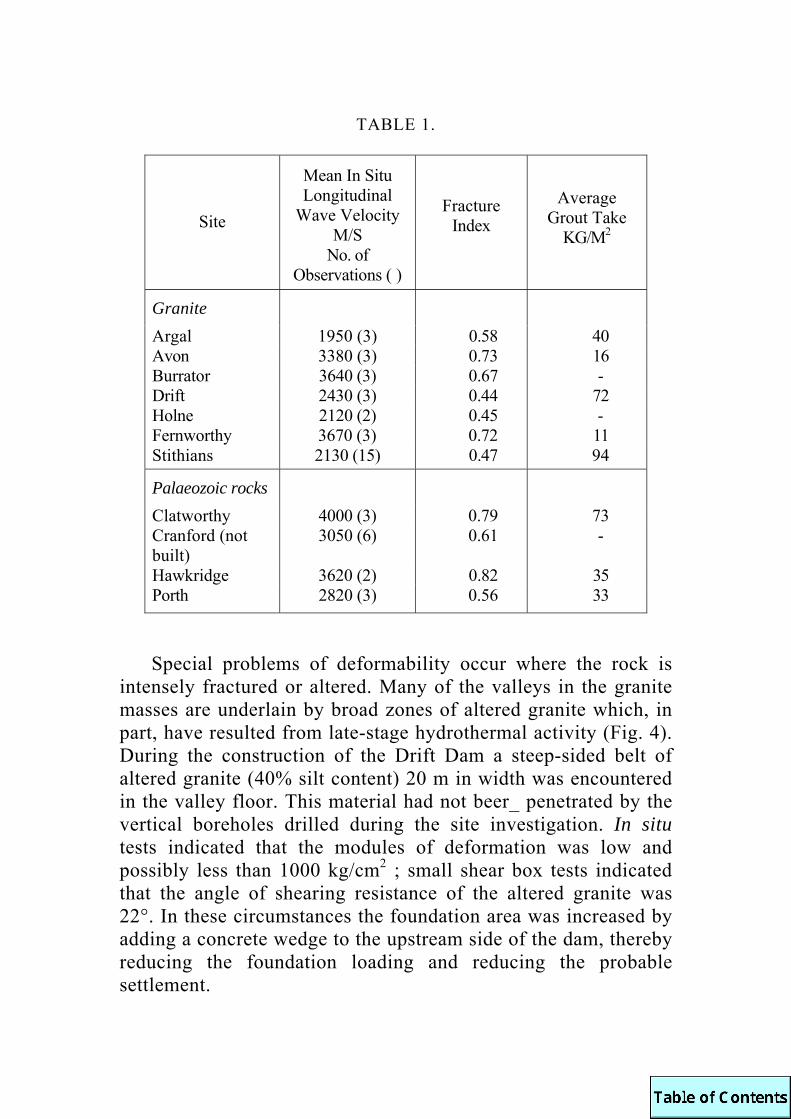
TABLE 1.
Special problems of deformability occur where the rock is
intensely fractured or altered. Many of the valleys in the granite masses are underlain by broad zones of altered granite which, in part, have resulted from late-stage hydrothermal activity (Fig. 4). During the construction of the Drift Dam a steep-sided belt of altered granite (40% silt content) 20 m in width was encountered in the valley floor. This material had not beer_ penetrated by the vertical boreholes drilled during the site investigation. In situ tests indicated that the modules of deformation was low and possibly less than 1000 kg/cm2 ; small shear box tests indicated that the angle of shearing resistance of the altered granite was 22°. In these circumstances the foundation area was increased by adding a concrete wedge to the upstream side of the dam, thereby reducing the foundation loading and reducing the probable settlement.
Site
Mean In Situ Longitudinal
Wave Velocity M/S
No. of Observations ( )
Fracture Index
Average Grout Take
KG/M2
Granite
Argal 1950 (3) 0.58 40 Avon 3380 (3) 0.73 16 Burrator 3640 (3) 0.67 - Drift 2430 (3) 0.44 72 Holne 2120 (2) 0.45 - Fernworthy 3670 (3) 0.72 11 Stithians 2130 (15) 0.47 94
Palaeozoic rocks
Clatworthy 4000 (3) 0.79 73 Cranford (not built)
3050 (6) 0.61 -
Hawkridge 3620 (2) 0.82 35 Porth 2820 (3) 0.56 33

FIGURE 4. Geological sections along the centre-lines of the Stithians, Argal and Sheepstor Dams, illustrating distribution of alteration in granite in relation to foundation depth. Altered granite is shown stippled. Vertical lines in Sheepstor cross-section represent quartz veins.
Special problems with regard to strength and deformability occurred in the case of the Stithians Dam located five miles north-west of Falmouth within the outcrop of the Carnmenellis granite. The dam was constructed in the period 1962-64 on behalf of the Stithians Joint Water Committee. The rock founda-tions of the dam are composed of medium grained muscovite-biotite granite with porphyritic felspar and quartz The near surface rocks are severely weathered to a depth of about 1.5 m being converted to a gravelly granitic sand with occasional core stones distributed along the valley sides. With depth, the rock becomes fresher and the excavations and boreholes have demon-strated that essentially fresh rock occurs at a depth of 15 to 20m.

Three main joint-sets are present: - A-joints : These joints, which trend ENE-WSW, are vertical or
steeply dipping and form the main joint set at the site. The mean joint separation is about 0.5 m with a range between 250 mm to 1.0 m. The joint surfaces are relatively smooth, being locally dis-coloured or infilled by thin seams of chlorite.
B-joints: This joint set trends NNW-SSE and individual joints are typically vertical. The mean joint separation is about 0.5 m with a range of 0.1 to 2.5 m. Joint surfaces are typically rough and kaolinisation has taken place along occasional fractures.
C-joints : These joints essentially parallel the topography and appear to be related to stress relief and other processes associated with weathering. The joint frequency decreases from an average of about 100 mm immediately below the ground surface to 0.7 m at a depth of 20 m. The near-surface joints are partially infilled by altered granite debris from which the fines (silt-sized felspar and mica predominantly) are readily removed by internal erosion.
A local mineral parallelism plunges steeply north-eastwards.
Two zones of altered granite underlie the valley floor, trending parallel to the 13-joint set. The major zone has a width of about 13 m and the more intense influence of kaolinisation extends to a depth of some 22 m. This altered rock contributed to the selection of the dam-type ultimately constructed. The foundation conditions on the valley sides are suitable for a mass gravity dam but this would have necessitated excessive volumes of excavation and concrete in the broad foundation area of the valley floor. It was decided to replace the central section of the dam by a constant radius arch and to realign the flanking gravity wings to carry the arch loading. Such a design provides an economic solution, necessitating minimum excavation and concrete. The total length of the dam is 260 m and is approximately 22 m above the original ground level and 42 m above the deepest foundation

level ; the arch has a span of 50 m and a radius of 58 m at the upstream face. The gravity tangential wings are thickened on the upstream face for a distance of 43 m to provide extra weight to help resist the arch thrust.
The exposed rock foundations were mapped geologically and, in order to provide a quantitative measure of rock quality, seismic velocity measurements were made in the rock foundations both during excavation and prior to concreting. At an early phase of excavation, it was revealed that the in situ velocity measurements in the intended position of the arch abutments were low, ranging from 1,600 to 800 m/sec. The contributory factor to this observa-tion was the presence of C-joints which had, in part, lost their infilling as a result of internal erosion arising from groundwater draining into the excavations. It was, therefore, decided to carry out further excavation and, also, to consolidate the arch abutments by low pressure grouting from the rock surfaces ; subsequently further consolidation grouting was carried out after some concrete had been placed. The mean grout take was equivalent to about 2% void infilling. Observations made at this time demonstrated that the in situ seismic velocity was more than doubled by the treatment, to a mean value of about 4,150 m/s indicating the effectiveness of the grouting. The arch loading is carried from the gravity abutments into the dam foundations. On the right bank, the C-joints are unfavourably orientated in that they daylight on the downstream side of the dam. A extensive series of laboratory shear tests were carried out on the three joint-types and it was concluded that design values of 40° could be used for the angle of shearing resistance for the A and B/C joint sets, respectively. Stability analyses, using these parameters, have indicated that under normal loading, and full uplift, the dam has a factor of safety in excess of 5. The overall stability condition is further improved by a system of foundation drains together with 75 mm diameter drilled boreholes extending up into an inspection gallery within the dam. Observations indicate that there is only limited uplift below the dam foundations
Seepage below dams such as Stithians is reduced by injecting grout (a cement-water mix) into the rock mass through a series of boreholes drilled as a curtain along the upstream side of the dam. The average quantity of grout injected, measured in kg. of

cement per m2 of curtain for various dams is summarised in Table 1. It will be recognised from these data that there is a general increase in the mean grout take with decrease in rock quality as indicated by velocity and Fracture Index. In older dams constructed before grouting was introduced, the standard technique was to excavate a trench about 2 m in width to sound rock and then infill the trench with concrete or clay. In the case of the Sheepstor embankment, on Dartmoor, a trench 25 m in maximum depth was excavated in altered granite for a dam impounding about 4 m of water (Fig. 4).
4. Comment It is clear that there will be a continuing need for the con-
struction of small reservoirs in South West England to satisfy the increasing public demand for water and a rising population. The geological problems to be encountered will in the main echo those that have been met and satisfactorily solved in the past.
KNILL, J. L., 1970. The application of seismic techniques in the prediction of grout take in rock. In situ investigations in soils and rocks, BRIT.GEOTECH.SOC. : 93-100.
1972. Assessment of reservoir feasibility. Q.JL.ENG.GEOL., Vol. 4 : 355 365.

THE INFLUENCE OF WEATHERING ON THE LAYOUT OF QUARRIES IN SOUTH-WEST ENGLAND
by W. R. Dearman and P. G. Fookes
Abstract. An engineering classification of weathered rock is given, and this, combined with structure, lithostratigraphy and geomorphology, is used as a basis for assessing the influence of weathering on the layout of quarries in S.W. England. Meldon Quarry and dolerite quarries south of Dartmoor are used as illustrations.
1. Introduction
In South-west England intensive weathering is associated with a succession of erosion levels into which the present river gorges have been incised. The region has not been glaciated, and in what was a periglacial environment during glacial times the products of weathering have generally been preserved on the erosion platforms beneath a variable cover of solifluction (head) deposits. The oldest of these erosion surfaces may be Miocene in age or even older (Edmonds et al. 1969, Fookes et al. 1971, fig. 12), but even on the lowest surfaces so far examined susceptible rock types have been found in a completely weathered state.
It is the purpose of this paper to illustrate, using selected examples, the effect of weathering and denudation history associated with the formation of successive erosion levels on the location, layout, and operation of quarries in South-west England. The study was begun in Meldon Quarry where working quarry faces provide cross-sections from the present surface to more than 150 ft below ground, and the influence of weathering on both quarrying and the properties of materials is well displayed. The rock types and the geological setting at Meldon are somewhat unusual, and other examples have been sought beyond the influence of the granite. Dolerite quarries in a wide belt south of Dartmoor and westwards into Cornwall show a similar topographical control of the distribution of weathering effects.
2. Engineering classification of weathered rock Classification of rock for engineering purposes requires the use
of a simple rock name amplified by geological characteristics which can be determined easily in the field. The latter may

involve a 'grade' of weathering classification, and simple index tests or observations. In the field descriptiorn of exposures, for example those in Meldon Quarry discussed later, each was examined and recorded systematically in the following stages :
(i) description of each rock type in engineering geology terms for each weathering grade, in a standard order "colour, grain size, structure and texture, discontinuities, weathered state, alteration state, minor lithological characteristics, ROCK NAME, estimated mechanical strength, mass permeability," and other terms indicating special engineering characteristics.
(ii) determination of the distribution of each rock type. Stages (i) and (ii) involve both qualitative and quantitative estimates of some aspects of the engineering behaviour of the whole quarry face.
(iii) preparation of a drawing of the quarry face showing, for example, individual lithological types, the position and physical nature of all major bedding, joint and fault discontinuities and discontinuity frequency over the whole face, and the distribution of weathering grades in each lithology present.
Stage (iii) was carried out on Sin x 4in Polaroid photographs annotated in ink in the field to provide a permanent record of the orientation, size and engineering geological details of the exposure. This drawing was then used to record the locations and values of field and laboratory tests, such as:
(iv) Schmidt Hammer Values or Pocket Penetrometer Test Values.
(v) Localities of samples for the Field Point Load Test or its laboratory equivalent, engineering petrographic examination, bulk density, porosity and other laboratory determinations.
Three main features are used to qualify the rock name : the weathering grade, a fracture spacing classification or index, and a strength classification or index. (i) Weathering grade classification. A slightly simplified version of the authors' classification scheme (Fookes et al. 1971, table 2) is given in Table 1 in which the engineering properties are after Little (1969). This classification has so far been applied only to rocks in the south-west of England, and grades should be assigned ideally for a fully trained person.

TABLE 1. Engineering grade classification of weathered rock.
(ii) Fracture spacing classification. A fracture spacing index should preferably be determined directly on the rock face, but may also be estimated from the average size of cored material or loose material derived from a rock face by blasting or natural processes. The following scale has been used :
Term Fracture Spacing Index millimetres
Extremely High EH If >2000 Very High VH 600 - 2000 High H 200 - 600 Medium M 600 - 200 Low L 20 - 60 Very Low VL 6 - 20 Extremely Low EL <6

The spacing of fractures is particularly important in quarrying, since this affects the degree of freedom available for displacements during blasting. Other significant features are their orientation, persistence, tightness, roughness and the nature of any weathered lining or infilling.
(iii) Strength classification. A simple field test is required to estimate rock strength, preferably a test requiring no specimen preparation. The point load test, which gives a measure of the tensile strength of the specimen, has been found suitable for this purpose. Two quantities are measured, the thickness D of the specimen between the test platen points and the force P required to break the specimen. The point load strength index Is, the ratio P/D2, is closely related to the unconfined compressive strength (D’Andrea et at. 1965) and the following logarithmic scale has been used :
Term Point load strength index IS , KN/m2
Equivalent uniaxial compressive strength
KN/m2
Extremely high strength EH >10000 > 160000 Very high strength VH 3000-10000 50000 - 160000 High strength H 1000-3000 16000 - 50000 Medium strength M 300-1000 5000 - 16000 Low strength L 100-300 1600 - 5000 Very low strength VL 30-100 500 - 1600 Extremely low strength EL <30 <500 Some of the limitations of the point load test are briefly discussed by Fookes et al. (1971: 150).
3. The geological setting of Meldon Quarry The geology of the Meldon area is well known (Dearman
1959, Edmonds et al. 1968) and will only be summarized here. In the Lower Carboniferous inlier, the stratigraphical succession is:
Meldon Chert Formation 240 ft Meldon Shale and Quartzite
Formation (including Meldon Volcanic Beds)
about 480 ft Meldon Slate-with-lenticles
Formation ?
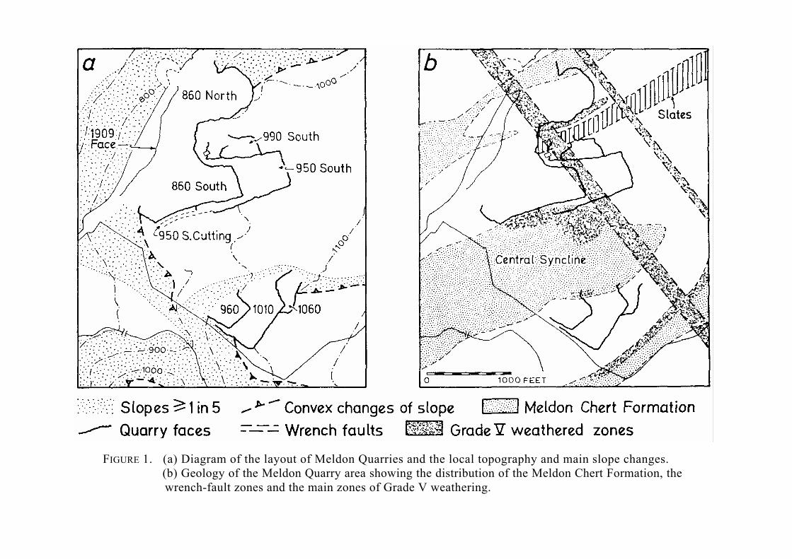
FIGURE 1. (a) Diagram of the layout of Meldon Quarries and the local topography and main slope changes. (b) Geology of the Meldon Quarry area showing the distribution of the Meldon Chert Formation, the wrench-fault zones and the main zones of Grade V weathering.
Distribution of the different formations is determined by over-folding and related strike faulting, and on a large scale two main anticlines are separated by a central syncline (Edmonds et al. 1968, fig. 11). The folds are intruded by two types of dolerite, and all rock types are contact metamorphosed by the adjacent Dartmoor granite. Tertiary wrench-faults trending NNW-SSE, subparallel to the dip of the beds, affect all rocks in the Meldon area and have produced intense brecciation extending over exposed widths of 9 ft (Fookes et al. 1971, p1.5)
4. Engineering appraisal of quarry faces at Meldon
The working quarries at Meldon provide 'fresh' faces, to depths of up to 150 ft below ground surface, in which the effects of long-term weathering have been preserved beneath solifluction (head) deposits of variable thickness. In this situation exposed weathering profiles range from Grade II immediately below over-burden to the greatest depth of exposure in, for example, hard mudstones, to the sequence Grade V to II in the contact metamorphosed limestones and cherts. An important point is that every quarry face shows weathering phenomena which, together with other geotechnical properties, may be assessed as an engineering appraisal of likely excavation conditions.
One example will suffice (Fookes et al. 1971, fig. 14) as an illustration of the effect of weathering on the engineering behaviour of a rock exposure. Cherts and limestones have had, as will be shown later, an important influence of the development of the various quarry areas at Meldon. At the north-eastern end of the 1010 Quarry Level (Fig. la) an exposure in the southern limb of the Central Syncline (Fig. lb & 2) has been left as a disused face. The face has been divided on the basis of weathered rock of Grades II, III and IV into three zones (Fig. 3a). These visual estimates of the weathered state of the rocks have been substan-tiated by measurements, on five traverses made at right angles to the bedding, of the spacing of bedding discontinuities and the total thickness of weathered Grade V material (soil) along the bedding planes. Such determinations, supplemented by assessment of fracture spacing (Fig. 3b) and measurement of the point load strength of selected samples (Fig. 3c) provide the bases for the assessments presented as Figure 4.
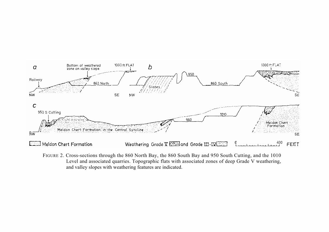
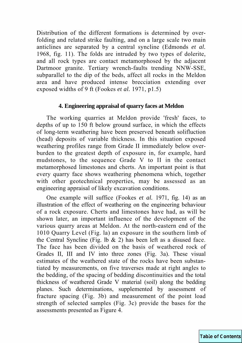
FIGURE 2. Cross-sections through the 860 North Bay, the 860 South Bay and 950 South Cutting, and the 1010 Level and associated quarries. Topographic flats with associated zones of deep Grade V weathering, and valley slopes with weathering features are indicated.

The field engineering appraisal (Fig. 4c) of likely excavation or quarrying conditions takes into account factors such as weathering grade, fracture index and strength index. It is self evident that broken or weak rocks should be easy to excavate, but the relationship between strength and fracture index has been used (Franklin, Broch and Walton 1971 ; Franklin 1970) as an index of likely ease of excavation. Precise location of the blast, rip or scrape areas on the graph (Fig. 4b) depends on the influence of other rock properties, on local conditions and on the mechanical capability of the excavating equipment. It should be noted that in an engineering appraisal the mapped boundaries do not neces-sarily correspond with bedding or with boundaries between rock types.
Figure 4a shows the test results obtained for cherts and limestones related to the weathering grade of the samples. The narrow spread of fracture spacing values in the high to extremely high strength range can be explained in terms of difficulty of obtaining test samples without coring the quarry face ; visual assessment of quarry faces with high to extremely high fracture spacings suggest how the range of tests values should be expanded. The high strength values for rock weathered to Grades II-111 is an intrinsic property of the rock, and is independent of fracture spacing.
There are three zones in the face ; the area at the base of the highest part of the face which would require to be blasted to fracture the rock coincides with the region of very high fracture spacing and extremely high strength, but with Grade III weathering. The two other areas on the quarry face with very high fracture spacing are surrounded and penetrated by rocks with the same weathering and strength characteristics but with a high fracture spacing. Consequently, blasting would have to be used to loosen the rock along existing discontinuities (Fig. 4c) in order to permit excavation. In contrast, the area of very high strength and medium to high fracture spacing could be removed by ripping because the rock is weathered to Grade IV. Present quarrying practice bears out these observations.

FIGURE 3. Geotechnical properties of an exposure of cherts and limestones
in the 1010 Level, Meldon Quarry. (a) weathering zones defined in terms of grade ; (b) discontinuity spacing variation ; (c) strength zones determined by point load strength tests.
(after Fookes et al. 1971. fig. 14).
5. Factors influencing the development of Meldon Quarry In the type of structural setting described above a quarry
could most conveniently be developed along the strike of the beds, thus minimizing the unfavourable effect of the variable dip of the strata on the ease of working, stability and safety of the quarry faces. Quarrying along the strike would, in this case, be facilitated by the presence at approximately 50 ft intervals of master vertical dip joints extending through heights of more than 150 ft. That there is not one single, very large working quarry face at Meldon indicates that other factors have influenced quarry development.
The quarry has, since its inception, been worked for railway ballast. For this purpose a rock should have high strength and durability, a low aggregate crushing value, a high resistance to abrasion, and should provide on crushing an angular rather than a flaky aggregate. Typically the rock should not possess a marked slaty cleavage and at the most should be weathered to Grade II.
(a) Early development Meldon Quarry was developed from the south wall of the
railway cutting in which there was the fortuitous combination of the first exposure of rock suitable for railway ballast west of London and a location before the highest point on the line west of Exeter had been reached. The railway cutting was made at an elevation of about 850 ft through the 1 in 5 valley slope of the West Okement River which was incised into the older 1000 ft platform (Fookes et al. 1971, fig. 7). As can be determined from the present north face of the cutting the rocks were predominantly weathered to Grade II ; most rapid development took place along the strike of the chert exposure at the northern end of the cutting and as the face increased in height the exposures included thin beds of impure limestone which were completely weathered to Grade V and thicker beds which were weathered to Grade IV with very large lithorelics.
(b) Later development Subsequent development of the quarry, particularly since
1946, was directed to the exploitation of large panels of rock weathered to Grade II immediately below the overburden, with the necessary additional condition that the rocks should not be slaty. It is the weathering to Grades IV and V of the limestones,

FIGURE 4. Engineering appraisal of the exposure of cherts and limestones
in the 1010 Level, Meldon Quarry.
(a) classification diagram for cherts and limestones from the Meldon area, showing the relationship between fracture spacing If, point load strength IS , and weathering grade ; see table in text for values of fracture spacing and strength.
(b) subdivision of the classification diagram (a) in terms of likely ease of excavation ;
(c) engineering appraisal of the quarry face in terms of likely excavation conditions set out in (b). (after Fookes et al. 1971. figs. 8, 9 & 14d with additions).

concentrated towards the base of the Meldon Chert Formation, that has been mainly, but not entirely, responsible for the definition of quarryable areas. The Meldon Chert Formation forms four separate outcrops within the Lower Carboniferous inlier, and these delimit the three main quarries (Fig. 1). A second factor controlling quarrying is also structural but of a different kind. The Tertiary wrench-faults have guided deep weathering, breaking up the strike continuity of otherwise extensive panels of Grade II weathered rock.
Distribution of weathering Grades IV and V is thus controlled by:
(i) the presence of a topographic flat on which deep weathering has taken place.
(ii) the presence and structural repetition of the Meldon Chert Formation, and
(iii) the presence of wrench-fault zones. Preservation of fragments of the weathered areas at the surface has been determined by a denudation history dominated by fluviatile denudation and intermittent river rejuvenation.
The restraints on quarrying in the three main areas at Meldon (Fig. la) will now be described and discussed. The 860 North Bay. This quarry has been worked on one level only into the valley slopes below the 1000 ft platform and has cut into the 1000 ft platform on the southern face. On the valley slopes (Fig. 2) only the lower parts of the deeply weathered zone in the Meldon Chert Formation are preserved in the present 860 North Bay.
The southern face of the quarry is a strike section and quarrying has mainly been limited by the occurrence of slates of the Meldon Slate-with-lenticles Formation in the lower part of the face. A thin skin of the Meldon Chert Formation at the quarry top, extensively weathered to Grade IV, has been partly removed by quarrying. A more effective restraint to quarrying along the strike of the beds was the presence of the wrench-fault zone. To the south at the quarry top, the outcrop of the Meldon Slate-with-lenticles Formation and the chiastolite slates at the base of the Meldon Shale and Quartzite Formation formed a slaty barrier to extension of quarrying in that direction. Additionally, in the vicinity of the wrench-fault zone the slates are weathered to Grades IV to V.

The 860 South Bay and the 950 and 990 South Bays. Present quarrying in this area is entirely within the 1000 ft platform and therefore the effects of weathering are particularly important. The northern limit of the quarry face is the chiastolite slate belt ; The southern limit at the 860 level is just below the inverted base of the Meldon Chert Formation. At the western end of the 'Gullet Back' (Edmonds et al. 1968: 41) the weathered chert beds have been broken into at the quarry top and the depth of the weathered zone was explored by means of a deep pit. The weathered zone in steeply dipping limestones and cherts is at east 100 ft wide, and the 950 South Cutting was driven along the strike of the completely weathered beds in order to open up the present higher levels above the 860 South Bay. The outcrop of the weathered beds is limited to the east by the plunge of the central syncline (Fig. 1) and in the southern limb of the fold the outcrop of the same weathered limestones has determined the northern limit of quarrying in the 960 level (Fig. 1& 2). Depth of the zone of Grade V weathering has been proved to 50 ft with no sign of a change of grade at that depth.
The 960, 1010 and 1060 Levels. Quarrying in these areas has not yet reached a southern limit, but hand-dug pits up to 12 ft deep have again revealed a zone of Grade V weathering, immediately below the overburden, near the base of the steeply dip-ping Meldon Chert Formation. The probable limits of outcrop of the Grade V zone have been determined (Fig lb), but the depth is unknown and is assumed, by comparison with the 950 South Cutting, to be greater than 50 ft. Exposures of this horizon of the cherts and limestones in the bed of the Red-a-van Brook are poor, but in one thick bed of altered limestone the wollastonite porphyroblasts are completely weathered. Neighbouring cherts, altered to blackand-white calcflintas are weathered to Grades II and III.
The effects of wrench-faulting. The two proven wrench-faults (Fig. lb) are zones up to 200 ft wide cutting across the strike of the beds in a direction sub-parallel to the major vertical dip joints. Relatively narrow bands of complete brecciation follow the main fault trend, but within the fault zone itself and splaying off on both sides are narrower zones of brecciation. These latter die out into ordinary dip joints away from the fault zone. In rocks other than those of the Meldon Chert Formation, the breccia alone

provides a locus for Grade V weathering, and the zones of Grade V weathering shown along the fault zones in Figure lb should be interpreted in this way
If highly weathered, the fault zones break up the strike continuity of quarryable blocks of ground already delimited by the occurrence of slate and completely weathered beds of the Meldon Chert Formation.
6. Weathering in dolerite quarries in south Devon All the dolerite quarries so far examined are now worked on
more than one level, having been opened originally at a low topographic level on valley slopes. With continued development they have been worked back to the topographic flat into which the valley slope has been incised. The highest quarry level has invariably been opened to remove the more weathered material of Grades III - V before quarrying the underlying better quality Grade II weathered rock.
The top of Pitts Cleave Quarry (SX502762) near Tavistock is at 550 ft ; at Wilminstone Quarry (SX490757) near Tavistock the higher level cuts into the 500 ft contour ; at Torr Quarry (SX744480) East Allington into the 450 ft contour ; and at New England Quarry (SX596545), near Yealmpton, into the 300 ft contour. The 300, 450 and 500-550 ft heights all appear to be the levels of distinct topographic flats, and from the initial survey the weathering effects at the surface appear to reach higher grades on the higher topographic levels, More work is needed on this aspect of weathering, but there is certainly a topographical control of the present distribution of weathering in these quarries (Fig. 5a, b). Successive erosional levels may be correlatable with successive phases of weathering, leading to the possible super-position of weathering effects on all but the youngest surface (Fig. 5c).
7. Summary and conclusions The rock types and geological setting at Meldon are some-
what unusual, but the area serves to demonstrate the importance of "fossil" weathering effects, which may have survived later denudation, on :
(i) the location, layout and operation of quarries, (ii) the suitability of natural materials for a particular use, (iii) the likely performance of the material in use.

FIGURE 5. The general setting of quarries and topographic flats.
(a) typical dolerite quarry setting with early development in Grade II dolerite on valley slope ; (b) subsequent development of (a) with necessity of higher quarry levels to remove Grades Ill-V before quarrying Grade II materials below ; (c) the general succession of topographic flats in S.W. England with possible polycyclic weathering phases WI, W2 W3, with W1 the earliest phase.
Fragments of entire deeply weathered zones, grading down-wards beneath a solifluction head from Grade V to Grade II, are preserved on high-level platform interfluves which have escaped denudation during later rejuvenation of the rivers and the cutting of more youthful valley slopes. There is a resultant contrast between the effects on quarrying of what may be assumed to be the root of a deeply weathered zone, such as that which affects the cherts of the 860 North Bay (Fig. 2), and the more completely preserved, very deep, Grade V weathered zone, for example, in the same beds in the 950 South Cutting. The former is a hindrance to effective quarrying without limiting the quarry area ; the latter completely inhibits quarrying and thereby closely defines the quarry area.
Examples of weathering in "dolerite" quarries remote from the granite serve to introduce the polycyclic nature of the weathering. Structure, as well as lithology, is an important controlling factor in weathering.

ACKNOWLEDGEMENTS. This work has been continued with the aid of a NERC research award which is gratefully acknowledged as is the continued help of quarry owners in the area.
D'ANDREA, C. B., R. L. FISCHER, and D. E. FOGELSON, 1965. Prediction of compressive strength from other rock properties. U.S. BUREAU OF MINES R.I. 6702.
DEARMAN, W. R., 1959. The structure of the Culm Measures at Meldon, near Okehampton, north Devon. Q.JL.GEOL.SOC.LOND., 115 : 65-106.
EDMONDS, E. A., and others, 1968. Geology of the country around Okehampton. MEM.GEOL.SURV.U.K.
M. C. MCKEOWN and M. WILLIAMS, 1969. South-west England. (Third Edition). B.REG.GEOL., London.
FOOKES, P. G., W. R. DEARMAN and J. A. FRANKLIN, 1971. Some engineering aspects of rock weathering with field examples from Dartmoor and elsewhere. Q.JL.ENGNG.GEOL., Vol. 4: 139-85.
FRANKLIN, J. A., 1970. Observations and tests for engineering description and mapping of rocks. PROC.2ND.CONG.INT.SOC. ROCK MECH. Belgrade, Vol. 1: 1-3.
E. BROCH and G. WALTON, 1971. Logging the mechanical character of rock. TRANS. INSTN.MIN.METALL. Sect. A, Vol. 80 : 1-9.
LITTLE, A. L., 1969. The engineeding classification of residual tropical Soils. PROC.INT.CONF.SOIL MECH. & FOUNO.ENGNG. 7th Mexico 1 : 1-10.

SOME EXAMPLES OF CLIFF FAILURE IN S.W. ENGLAND by M. H. de Freitas
Abstract : Numerous modes of failure can be observed in the cliffs of Devon and Cornwall. Three are briefly described in this paper viz, toppling, rotation and sagging. Geological structure largely controls the type of failure that is permitted to develop and in certain circumstances allows two or more compatible modes of failure to operate within one particular slide.
1. Introduction The cliffs in S.W. England expose many rocks and structures
which permit the development of a variety of failure mechanisms. Toppling, rotation and sagging are three that are briefly described in this paper. A fuller description of these and other failures is the subject of a forthcoming thesis.
2. Toppling Toppling is a mode of failure whose importance to slope
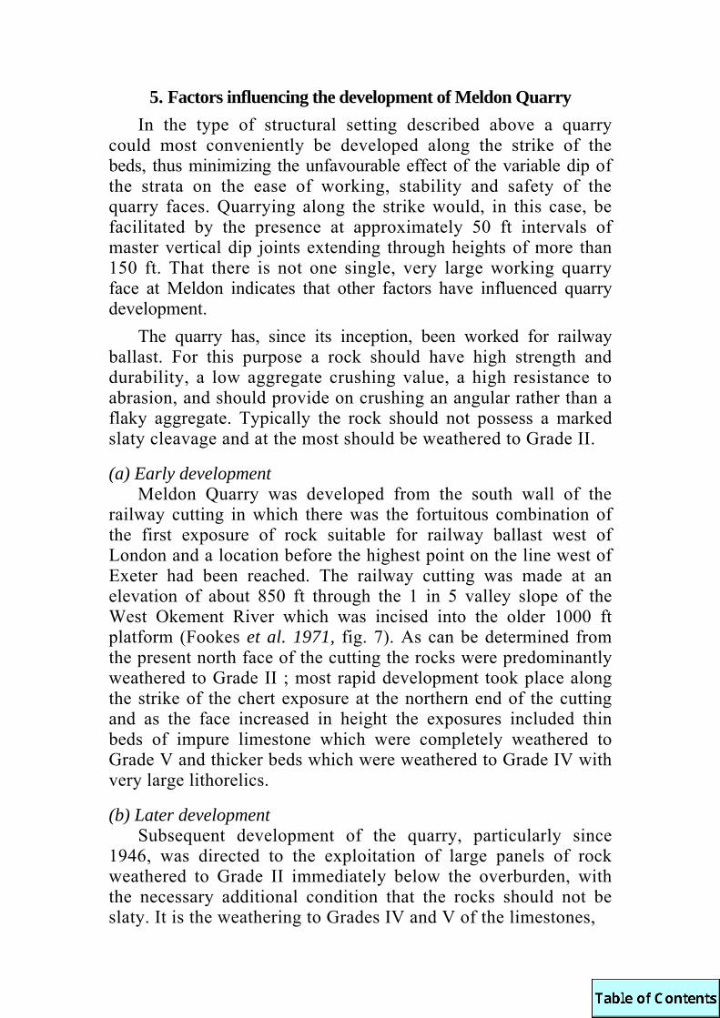
stability has only recently been more fully appreciated. (Ashby 1971). It occurs in situations where the centre of gravity of a unit of rock overhangs a possible pivot point within the rock structure. Figure 1 illustrates a simple situation where this occurs. The mechanics of the system can be studied with the aid of the simple model described in the Appendix
Many parts of the coastline between Hartland Point and Bideford have a geological structure that is suited to this form of failure. The Culm in this part of Devon consists of sandstones and shales which have been irregularly folded about E-W trending axes so that they strike almost parallel to the shore of Bideford Bay. Dips are therefore directed either towards, or away from the Bay itself. Those areas where the direction of the dip is south, i.e. away from the Bay and into the cliffs, have a geometry which is little different from that shown in Figure 1. Figure 2 illustrates a typical section from that part of the coast.
In these situations marine erosion of the weaker shales exposed at the base of the cliffs eventually undermines the sand-stones which then topple and so leave the next shale horizon unsupported. Gradually the process creeps back into the slope
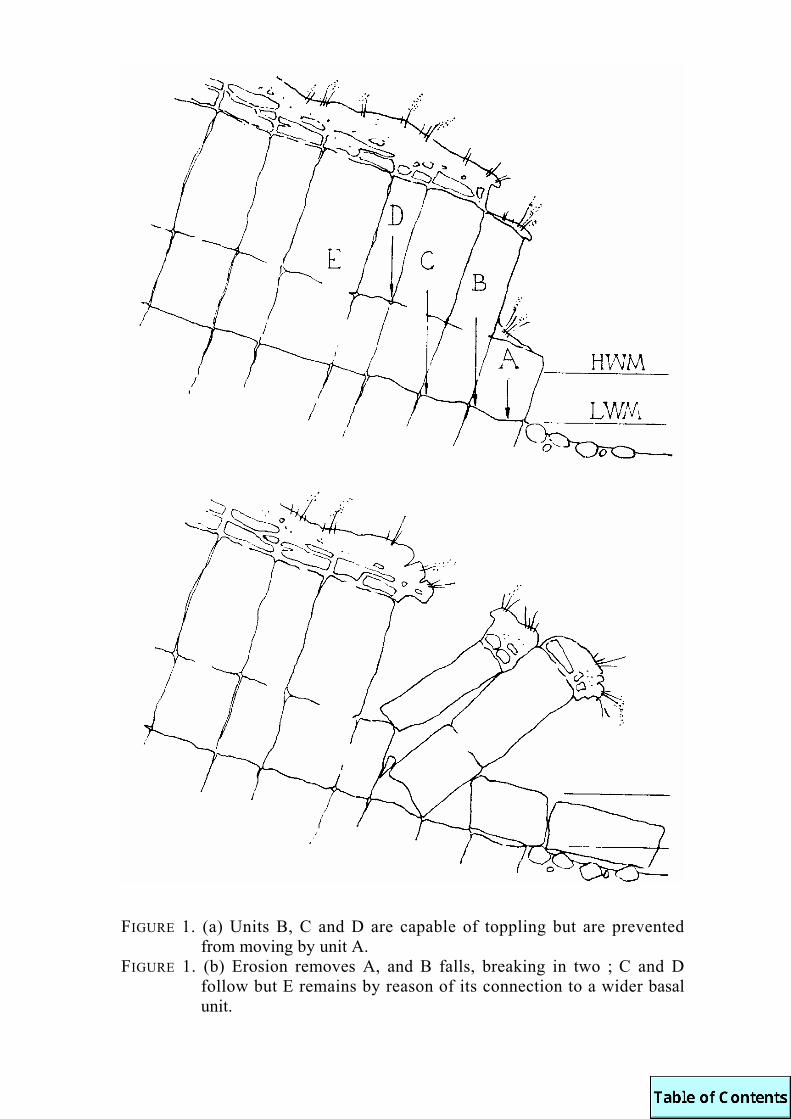
FIGURE 1. (a) Units B, C and D are capable of toppling but are prevented from moving by unit A.
FIGURE 1. (b) Erosion removes A, and B falls, breaking in two ; C and D follow but E remains by reason of its connection to a wider basal unit.
FIGURE 2. Alternating series of sandstones and shales dipping in a southerly direction, i.e. into the cliffs.
until a point is reached where the geometry of the rock structures prevents further toppling from occurring. Plate 1 illustrates the process in operation. Toppling was initiated in this section by the weathering of a thin shale horizon to a soft clay. This was progressively squeezed, from its initial position within the structure, out onto the face of the slope so permitting the overlying sandstone to topple forward. This started the failure which gradually involved more and more of the slope.
Seeing the process at work on a small section of cliff prompts the question of whether the mechanism is also controlling the general stability of larger sections which rise to a height of 500-600 ft above sea level between Bucks Mills and Clovelly. Unfortunately only the superficial character of the cliffs can be studied in any detail, however certain features of their shape and size do suggest that toppling mechanisms may have been, and may continue to be, at work within them. There are 3 points to note : -
(a) Many sections of cliff along this stretch of the coast are covered by a thick mantle of scree. This is open, contains a great variety of 'grain' sizes and is unlike the surface of a rock mass which has suffered rotational failure. Model studies of the type outlined in the Appendix show that toppling is

PLATE 1. Toppling failure in the Culm at Bideford Bay
associated with a considerable loosening of the rock structure and the development of an upper zone of mobile sliding units which if seen in the field would probably resemble a scree of loose, tumbled rocks.
(b) Such sections have a low dipping, planar slope profile which terminates at the crest of the slope with a steep cliff. This is not the profile that would normally result from a rotational failure however it is reproduced by the toppling model.
(c) Behind the crest of these slopes extends a zone of disturbed ground. This is manifest at ground level by a series of ridges and hollows which run parallel to the crest of the slope. The ridges are known to be of hard rock and the hollows to be chasms that are filled with loose debris which is covered by a veneer of top soil. These are undoubtedly tension cracks at the tail and of some failure within the cliffs and as such are found associated with most forms of slope instability. However, a line joining the farthest of these features to the toe of the cliffs invariably makes an angle of approximately 30° to the horizontal and this is the angle of the surfaces about which toppling is seen to occur on the more exposed parts of the cliffs near the shore ; see for example Plate 1.
Most of this ‘evidence’ is circumstantial but it does support the conclusions from other studies on this coast which indicate that a number of failure processes are at work. Whatever their mode, i.e. planar, rotational or toppling. their development is markedly controlled by the structure exposed at any section of cliff for a completely different state of stability exists in the same rocks exposed on the coast between Hartland Point and Bude. Here the cliffs are orientated at right angles to the strike of the Culm and steep cliffs are generally developed.
3. Rotation Rotational failure of the type seen in clays does occur in
areas where fragmentation is intense and gives the rock mass either a very small 'grain' size or a high degree of structural homogeneity. Examples of this type can be seen along the Lizard between Cadgwith and Poltesco. The slides are poorly exposed but their topographical features are quite distinct. From a distance they resemble the imprint that might be left by a giant horse stamping his hoof into the top of the cliff.

FIGURE 3. Negative vertical movements, in feet, recorded between 1966-68.
Recent surveying confirms this trend. The front pinnacles of the cliff fell in January 1971.
A better exposure of rotational failure has recently been visible on the west side of the Lizard at Halsferran Cove. It developed in a folded series of Devonian shales and sandstones and assumed a curved, but non-circular failure surface which was exposed on the face of the cliff itself. The top of this slide has been surveyed since 1966 and the results reveal that recent movements have not occurred about the failure surface which can be seen but around another further in the cliff itself (Fig. 3).
This suggests that the rock mass above the original failure surface has moved as far as it can for the present and that the geometry of the sliding mass has regained a structural competence which is sufficient to temporarily support the front of the slope. The original movement will probably continue once the geometrical cohesion of the sliding mass is lost. Meanwhile the original slide is now moving in conjunction with an additional

section of the cliff which is situated at its rear. At the present the cause of the slide is not definitely known but it is likely to have been initiated at a time when water pressures within the cliff were of such a magnitude that marine erosion at the toe was sufficient to precipitate a large failure.
4. Sagging
Sagging is a new term which has been coined to describe a mode of failure that is closely linked to the development of geometrical cohesion within a moving mass of rock. Good examples of this process occasionally develop on the north face of Baggy Point. Here the Devonian sandstones and shales dip at approximately 65-70° into the Point. Occasionally a failure in one of the shale horizons exposed on the face undercuts the sandstones that are above. These then sag, and promote a similar movement above them which can sometimes involve a sizeable volume of the cliff. Plate 2 shows this developed to a remarkable degree.
The stability of these slides is almost entirely controlled by the interaction of the separate constituent blocks and the removal of any one from the lower part of the structure will invariably cause the whole mass to collapse.
5. Conclusions The development of each of these modes of failure is
closely linked to the structure of the exposed mass and the 'degree of freedom' that is available for the mass to utilise ; this has been discussed elsewhere (de Freitas 1969). Although these failures are not commonly described from rock slopes they are not unusual and require no exceptional geological conditions for their formation. In fact rock slopes can fail in a variety of ways and it is quite likely that many of the slides which have occurred in the complicated rock structures of Devon and Cornwall have probably involved more than one mode of failure. Care should be taken when stabilizing such slopes to ensure that no mode is left free to develop as this could under-mine the work that may have already been completed.

PLATE 2. The remains of a sagging failure in the Baggy Beds on the scarp
face of Baggy Point
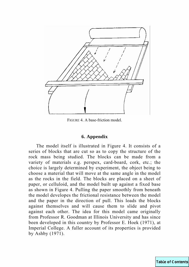
FIGURE 4. A base-friction model.
6. Appendix
The model itself is illustrated in Figure 4. It consists of a series of blocks that are cut so as to copy the structure of the rock mass being studied. The blocks can be made from a variety of materials e.g. perspex, card-board, cork, etc.; the choice is largely determined by experiment, the object being to choose a material that will move at the same angle in the model as the rocks in the field. The blocks are placed on a sheet of paper, or celluloid, and the model built up against a fixed base as shown in Figure 4. Pulling the paper smoothly from beneath the model developes the frictional resistance between the model and the paper in the direction of pull. This loads the blocks against themselves and will cause them to slide and pivot against each other. The idea for this model came originally from Professor R. Goodman at Illinois University and has since been developed in this country by Professor E. Hoek (1971), at Imperial College. A fuller account of its properties is provided by Ashby (1971).

ASHBY, J. P., 1971. Sliding and Toppling modes of failure in models and jointed rock slopes. M.SC.THESIS, UNIVERSITY OF LONDON (ROCK MECHANICS RESEARCH REPORT No. T3. IMPERIAL COLLEGE).
DE FREITAS, M. H., 1969. The stability of rock cliffs in south west England. PROC.GEOL.SOC.LOND., No. 1654: 68-70.
HOEK, E. and J. M. BOYD, 1971. Stability of slopes in jointed rock. ROCK MECHANICS PROGRESS REPORT No. 9. IMPERIAL COLLEGE.
GEOLOGICAL INVESTIGATIONS FOR A PROPOSED OFFSHORE TUNNEL IN THE DODMAN POINT -
MAENEASE POINT AREA
by M. S. Money
Abstract. Assessment of tunnelling conditions and selection of tunnel routes, pipeline routes and portal sites was made by studying the dis-continuity pattern in the Dodman Phyllites and by mapping head deposits and coastal landslips. Geological mapping offshore showed that rocks similar to the Dodman Phyllites form an irregular outcrop on the sea floor extending to 3 km south and 2 km west of Dodman Point.
1. Introduction Extraction of china clay in the St. Austell area generates
approximately 82 tons of waste for each ton of kaolin produced. About 90% of the waste is quartz sand, rock and overburden which is placed on tips but the remainder is micaceous residue, some of which is discharged into the St. Austell and Luxulyan Rivers. Investigations were started in 1967 into alternative means of disposing of the mica and a scheme was proposed in which residues would be conveyed in a pipeline laid in a tunnel driven from the Dodman Point - Maenease Point area to an offshore outfall. For technical (but not geological) reasons the scheme has been abandoned in favour of constructing additional mica lagoons and back-filling disused pits. The paper summarises the geological information obtained for the tunnel scheme but does not deal with any other aspects of residue disposal.

Geological information was needed to assess the feasibility of the scheme and in particular to predict undersea tunnelling conditions, namely the rock types and rock defects likely to be encountered, the cover and support required for safety and the probable extent of overbreak and leakage. The selection of suitable portal sites and connecting pipeline routes was influenced by the topography, the solid geology and the presence of head deposits and coastal landslips.
2. Previous work Although there are numerous references in the geological
literature to the Dodman area the majority are concerned with the possible structural and stratigraphical relationships of the Dodman Phyllites to the Devonian rocks to the north and to the Lizard and Start complexes to the west and east respectively. Only three works provide useful local detail, the Geological Survey Memoir by Reid (1907) an outline of the structure by McKeown (1962) and an account of the geomorphology by Bird (1963). None of these accounts provided sufficient information to make an engineering assessment of the area and a fresh field investigation was therefore carried out. A limited study of literature and records relating to underwater mining in south Cornwall was also undertaken to assist in estimating the amount of rock cover required between the tunnel and the sea bed.
3. The Dodman Phyllites The rocks outcropping in the Dodman Point-Maenease Point
area are generally known as the Dodman Phyllites and although phyllites form a large part of the succession, slates, siltstones, sandstones and greywackes are also present The rocks have undergone repeated deformation (McKeown 1962) and any size-able outcrop shows folded bedding, one or two cleavages and a variety of faults and joints. Although detailed analysis of this complex structural situation could not be justified for engineering purposes it was considered advisable to examine the pattern and nature of the discontinuities in order to assess their effect on tunnelling.
(a) Cleavage As all lithologies are cleaved the attitude of the cleavages
was measured throughout the project area. The results in general confirmed McKeown's observations ; the first cleavage dips at

between 40° and 60° to the south east except in the vicinity of Dodman Point where the dip is less and more easterly in direction. The second cleavage also dips south east at 80°-90°. The main effect of the cleavages in tunnelling would be to increase the overbreak and this could be minimised by aligning the tunnel in a south-easterly direction. (b) Joints and Faults
Three sample areas, the east side of Hemmick Beach, Dodman Point and Maenease Point were selected for a statistical study of these fractures. The orientation and the nature of at least 120 fractures in each sample area was determined and over 500 readings were obtained in the area as a whole. The fracture pattern proved to be similar though not identical in the three sample areas. Three main types of fracture were found :
Faults-with-gouge Faults and joints with quartz infill ‘Clean’ joints
(i) Faults-with-gouge. These consist of a zone of shattered rock and clay gouge ranging from a few millimetres to about 2 metres in width and usually carry seepage. Most of these faults dip at 60° to 90° south east or north west but a few dip eastnorth-east and probably belong to the set of north-north-west striking wrench faults in south-west England. In the tunnel these faults would introduce seepage and the wider zones might ravel unless treated promptly.
(ii) Faults and joints with quartz infill. These fractures show a greater scatter in orientation but two main sets can be dis-tinguished, one dipping steeply north or south, the other dipping steeply east-north-east. Most of these fractures are tight but some, particularly in the second set, show horizontal slickensides and may be slightly open. Fractures of this type would contribute to overbreak in the tunnel if unfavourably oriented and if open would permit seepage to enter.
(iii) ‘Clean’ joints. These joints have no infilling apart from limonite staining in the weathered zone and occur in a wide range of orientations. Most of the joints however dip at 60°-90° and stereographic plots show preferred strike directions of north east, east south east and south south east. Joints of this type may contribute to overbreak but not to seepage except in the weathered zone where they may be open.

4. Head deposits Deposits of head mantle the sides and ffoors of valleys and
many of the coastal slopes in the area. In general the deposits consist of yellow to brown compact gravel to boulder size angular platy fragments of phyllite and other local rocks in a matrix of silty sand. The material is usually gap-graded but some cliff exposures show a crude stratification with lenses of sand and alignment of platy fragments. The material possesses considerable cohesion and is locally cemented. When well drained vertical faces 10 m high can stand without protection for many years. In places the head overlies fairly intact rock but there is often a transition zone of fractured disturbed material which is permeable and locally water-bearing.
5. Coastal Landslips Much of the coast between Hemmick Beach and Maenease Point
has been subject to landslips and rockfalls. The type and scale of slope failures can be related to three main factors :
(a) The orientation of discontinuities in the phyllites, principally the cleavage,
(b) The occurrence and depth of the head deposits, (c) The extent of the rock protection at the toe of the cliff s. The cliffs between Hemmick Beach and Dodman Point
appear to be the most stable part of the coast in the area and now exhibit only a few rock falls and minor sloughing of the head. The typical slope profile is a rock cliff about 30 m high topped by more gentle slopes rising to the 90-100 m level. Master joints control many of the cliff faces but the cleavage strikes at right angles to the general line of the coast and head deposits when present are only thin. Most of the base of the cliff is protected by the remnants of a raised rock platform.
The south-eastward facing slopes of Dodman Point itself are steep and very broken. Extensive rockfalls have occurred producing much large boulder debris and there has been mass movement seawards with a toppling type of failure opening up deep gullies parallel to the coast. Failures here appear to be guided by the seaward dipping cleavage and master joints striking east-north-east.

Between Dodman Point and Maenease Point there have been numerous slips, some of which extend to the full 90 m height of the coastal slopes and leave clearly defined semicircular scars. Although the smaller slips appear to be confined to the head the larger failures involve the underlying rock. On this section of the coast the cleavage dips seawards and there are thick deposits of head. Much of the toe of the cliff, particularly along Vault Beach is undefended.
There is no evidence to suggest that any of the major slips has been active in recent years. The scars of the largest slips are shown on the 1907 edition of the 1: 2500 map and do not appear to have been extended by further movement. The toes of the head slope along Vault Beach and some of the rock slips are attacked by waves and head is also being eroded where springs emerge. It was thought that slip movement might be renewed and this ruled out large areas of the coast for consideration in selecting a portal site.
6. Offshore geological mapping The main purpose of the offshore mapping was to determine
the seaward extent of the Dodman Phyllites. It was known from earlier but small scale mapping (Curry, Hamilton and Smith 1970) that Permo-Triassic rocks, in which undersea tunnelling would be very difficult, outcrop on the sea floor 2-4 km offshore.
Existing charts showed a rock reef extending southwards from Dodman Point and this was explored in detail during a hydro-graphic survey of the area. Echosounder traces showed a strong contrast between a relatively smooth bottom surrounding the reef and the irregular jagged profile of the reef itself. Feature mapping by plotting these two types of topography appeared to give the consistent pattern of rock outcrops shown on Figure 1.
The survey vessel was unable to handle a heavy corer and in the reef area a Shipek sampler was only able to recover seabed fauna and flora or the occasional loose boulder and was often damaged. Sampling and inspection of outcrops was therefore carried out by two divers who were already employed elsewhere on the project. 28 one-man dives were completed in 5 days to a maximum depth of 10 fathoms. 5 dives in sand areas and 23 in rock areas confirmed the distribution of outcrops deduced from

the bottom profile. Samples were prised from outcrops with a small crowbar. Visibility varied from 2 to 20 m and descriptions were obtained of the general form of the rocks and the ‘run’ of the outcrops estimated with a wrist-mounted compass. Accurate description of the underwater scene is part of the professional diver's stock-in-trade and it is thought that if more time had been available for surface training basic structural observations could also have been made. Positioning for all the offshore work was carried out with the Decca Navigator with checks by sextant on shore markers.
Rock samples recovered by the divers were all comparable to the Dodman Phyllites exposed on shore. The outcrop of the Permo-trias could not be firmly established although it is thought that it probably coincides with a belt of sand in which gravel occurs and within which a few Shipek samples of red sandstone and mudstone were obtained.
No geophysical surveys were undertaken as the combination of feature mapping and direct sampling had proved successful. It was also thought that a sparker survey would be unlikely to define rock defects such as fault zones or narrow sediment-filled gullies. If the outfall were to be located outside the proved limit of the phyllites then further investigation would be needed and this would include geophysical methods.
7. Conclusions The location of the tunnel portal was influenced by the overall
steepness of most of the coastline, the doubtful long term stability of the more accessible areas and the construction difficulties that could be expected if the tunnel were driven through head which would probably be water-bearing near its contact with the underlying rock.
The Dodman Phyllites were judged to be a satisfactory medium for tunnelling and it was considered that little temporary support would be required. Minimum overbreak would be achieved by driving the tunnel in a south easterly direction which would also intersect the majority of faults at a high angle. The offshore work demonstrated the continuity of the Dodman Phyllite outcrop. The seaward section of the tunnel was designed to
drain towards the land and a minimum cover of 100 ft of phyllites at the outfall was recommended. Figure 1 shows the proposed tunnel route through the phyllites Extension of the tunnel beyond the proved outcrop would require further investigation.
ACKNOWLEDGEMENTS. The author wishes to thank the China Clay Association and Binnie and Partners, Chartered Engineers for permission to publish the paper and Mr. C. M. Bristow and Dr. M. J. Ripley for helpful discussions. The hydrographic survey was carried out by George Wimpey & Co. and the diving by Strongwork Diving International Ltd.
BIRD, E. C. F., 1963. Coastal landforms of the Dodman District. PROC.USSHER .SOC., Vol. 1: 56-57.
CURRY, D., D. HAMILTON and A. J. SMITH, 1970. Geological and shallow subsurface geophysical investigations in the Western Approaches to the English Channel REP. No. 70/3. INST.GEOL.SCI.
MCKEOWN, M. C., 1962. Structural studies at Dodman Point Cornwall. PROC.USSHER.SOC., Vol. 1: 18-19.
REID, C., 1907. The geology of the country around Mevagissey. MEM.GEOL.SURV.U.K.

SLOPE STABILITY PROBLEMS IN THE CHINA CLAY INDUSTRY OF SOUTH WEST ENGLAND
by M. J. Ripley
Abstract. Although the detailed examination of excavated slopes is in its infancy ti has become apparent that an empirical approach will play a large part in the study of the problems. Increasing knowledge of the stability of tipped slopes plus experience gained from study of actual failures, has caused the Industry to modify some of its tipping techniques.
1. Introduction The China Clay Industry of Devon and Cornwall has been in
existence for nearly 200 years. At present it extracts over 25 million tons of material each year from its open pits. Only a little over 10% is sold, the remainder has to be disposed of, either in tips of various kinds, or in mica dams (tailings lagoons). The cumulative results of this work are numerous large pits and tips with the consequent problems of maintaining stable slopes. Pits today range up to 500 ft in depth and 100 acres in area. However, much larger pits are envisaged. China clay has been proven to at least 800 ft below land surface and pits up to 24 miles in length and 600 ft deep are presently being planned. Also tips over 300 ft high and mica dams of similar scale are under consideration. The problems of the excavated pit slopes in in situ material is considered separately from those of the tips and mica dams.
2. Pit Slopes Although detailed study of these slopes is in its infancy
certain factors have become apparent. The inherent variability of china clay ground is such that considerable difficulty will be encountered in determining many of the parameters necessary for stability calculations. The complex distribution patterns of un-kaolinised, partly kaolinised and fully kaolinised ground plus the frequently haphazard distribution and variation in scale and orientation of the numerous lodes will make analysis difficult. It is thought at present that empirical study may be the best approach.

For slopes 200 ft high it appears that the maximum slope angle can range from 30° to 65° depending on the degree of kaolinisation and the geological structure of the slope in question. Limited tests carried out to date indicate that fully kaolinised granite has an ‘effective’ cohesion of 0.01 KN/m2 and an ‘effective’ angle of friction of 36°. (The prefix ‘effective’ denotes that the shear strength parameters are in terms of effective stress). There is some evidence that a lower angle of friction may exist where the stress levels exceed 0.30 to 0.40 KN j m2.
3. Tips and Tailings Lagoon Slopes The Industry produces four basic types of waste. These are :
overburden, rock, 'sand' and micaceous residue. The overburden is the material overlying the kaolinised granite. It contains a high clay percentage. When tipped it has a low permeability. The rock is comprised of unkaolinised granite and lode material. The ‘sand’ is the coarse waste from first stage refining of the clay. Its particle size distribution usually lies between 0.1 mm and 10 mm. These three waste materials are disposed of in tips. The fourth type of waste, micaceous residue, is produced from second stage refining of the clay. It is tipped in slurry form into mica dams. It is formed of micaceous material most of which is finer than 0.2 mm.
Well documented failures have occurred in recent years in overburden tips, sand tips and in the retaining walls of mica dams. Post failure examination of the various slips has enabled the Industry to obtain considerable knowledge and experience of the stability of slopes in different types of tipped material. These studies have resulted in changes in many of the previous tipping practices.
(a) Reasons for failure Nearly all failures have taken place in the period October to
March inclusive. It would appear that climatic conditions play a part in waste tip stability. The higher winter rainfall and reduced evaporation result in higher water pressures developing in the waste piles. The type of failure is dependent upon the type of waste.
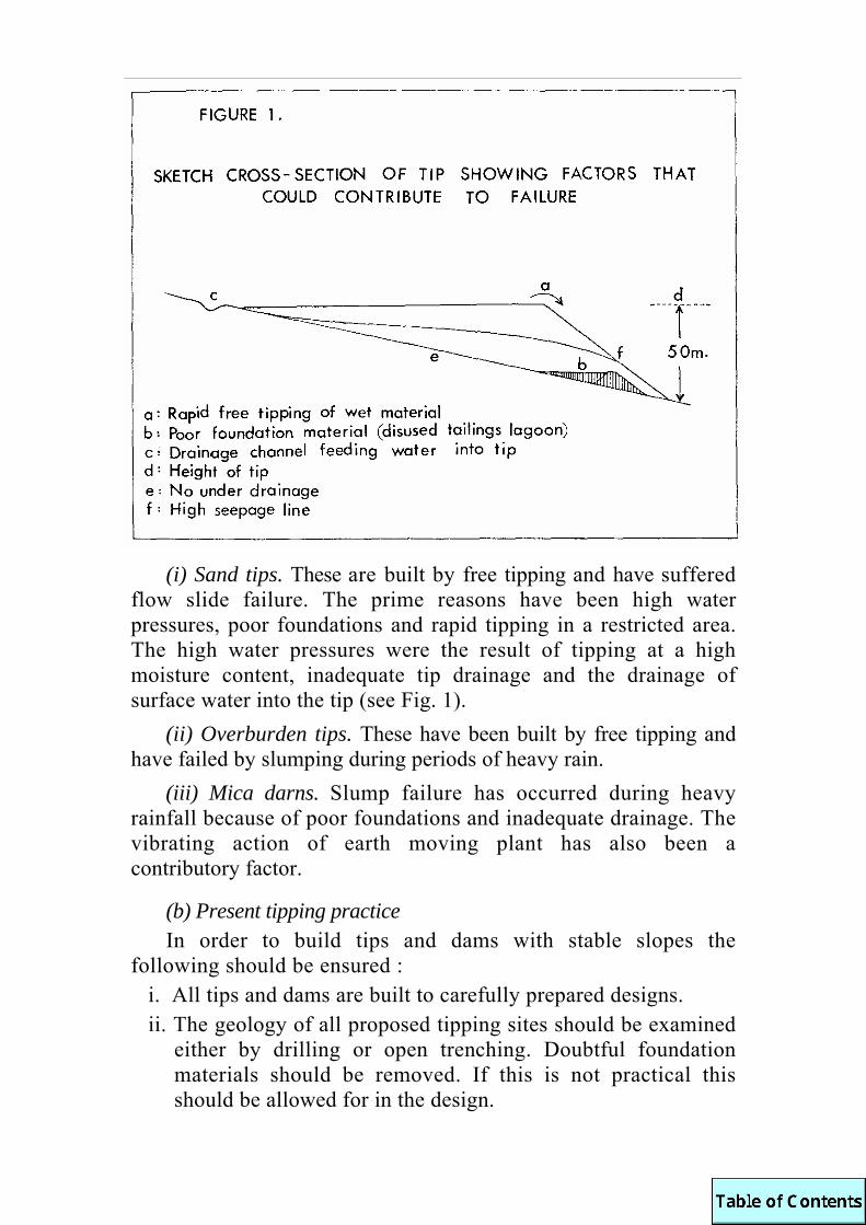
(i) Sand tips. These are built by free tipping and have suffered flow slide failure. The prime reasons have been high water pressures, poor foundations and rapid tipping in a restricted area. The high water pressures were the result of tipping at a high moisture content, inadequate tip drainage and the drainage of surface water into the tip (see Fig. 1).
(ii) Overburden tips. These have been built by free tipping and have failed by slumping during periods of heavy rain.
(iii) Mica darns. Slump failure has occurred during heavy rainfall because of poor foundations and inadequate drainage. The vibrating action of earth moving plant has also been a contributory factor.
(b) Present tipping practice In order to build tips and dams with stable slopes the
following should be ensured : i. All tips and dams are built to carefully prepared designs. ii. The geology of all proposed tipping sites should be examined
either by drilling or open trenching. Doubtful foundation materials should be removed. If this is not practical this should be allowed for in the design.

iii. The grading of the waste should be known. The tips if
possible should be homogeneous. Unless strictly controlled there should be no mixing of materials with very different particle size distributions.
iv. The drainage should be designed to cope with both naturally occurring water (springs, streams, precipitation) and water tipped with the waste. The possibility of artesian flow should be investigated.
v. The rate of tipping should be known and single point tipping at high rates avoided.
vi. The method of tipping should be stipulated. This is of considerable importance in mica dam construction as scraper built dams are inherently more stable than lorry built dams, all other factors being equal. This is because of the much higher in situ density developed in scraper built dams.
vii. Tips should be built in a series of lifts instead of free tipping over the complete height of the tip. This latter process has produced in the past tips with angle of repose slopes over 300 ft in height. In the case of conveyor built sand tips the bench height has been fixed at 25m (see Fig 2).

The geological aspects of colliery tipping in South Wales and
Somerset (Abstract) : by A. N. Lane
As a result of requirements eventually made law under the Mines and Quarries Act all classified tip sites whether future, active or disused must be subject to a detailed geological examination. The purpose of this examination is to determine any potential hazards that the geology may present to a site and to investigate any possible remedial measures that can be taken.
In Somerset and South Wales most tips were established long ago on valley sides for economic reasons. In South Wales, these valley sides are very steep, subject to high rainfall and prone to strong spring activity and to the effects of underlying landslips. Mining subsidence often aggravates an already bad situation by adversely affecting the hydrogeology. In some cases tip in stability does not develop or become apparent for many years after the cessation of tipping.
Examples of tip failure in the old tips are numerous, but rarely catastrophic. In some cases remedial action such as draining an aquifer or redistributing the spoil can be taken but in others the whole or part of the tip has to be removed - a process often made less expensive by the washing and recovery of coal from the tip.

THE MINERALOGY AND CHEMISTRY OF AXINITE REACTION VEINS CUTTING THE MELDON APLITE
by D. M. Mackenzie
1. Introduction The Meldon Aplite comprises a series of small, discontinuous,
sub-parallel dykes, intruded into thermally metamorphosed sediments on the north west flank of the Dartmoor Granite. The dykes lie parallel to the margin of the granite and along the strike of the country rocks which are folded in a NE-SW axial direction. Both the aplite and the surrounding sediments are crossed by a strongly developed joint system which has provided channelways for the circulation of pneumatolytic and hydrothermal fluids. It is the veins produced by the reaction of these fluids with the aplite which are described here.
The geology of the area and the aplite quarries was described by Worth (1920), and his structural and stratigraphical interpretation was later revised by Dearman (1959), Dearman and Butcher (1959) and Edmonds et al. (1968). Worth (1920) and McLintock (1923) have described the petrography of the aplite and a more recent summary is given by Edmonds et al. (1968). Accordingly only a brief account will be given here.
2. Petrography of the aplite The main body of the aplite, 20 m thick, is well exposed in three
quarries adjacent to Red-a-ven Brook. The rock comprises subhedral laths and prisms of twinned albite together with anhedral orthoclase perthite and quartz. A pale brown-colourless mica occurs as small ragged flakes. Subsidiary fluorite, tourmaline, topaz and apatite occur in variable proportions, some areas being enriched in one or more of these minerals whilst others are depleted.
Coarse pegmatitic veins ramify through the aplite bearing a wide variety of, sometimes unusual, accessory minerals. These have been described by many authors, (Worth 1920, McLintock 1923, von Knorring 1951, Kingsbury 1966), and a more recent list may be found in the Okehampton Memoir (Edmonds et al. 1968).
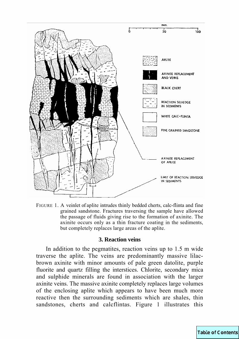
FIGURE 1. A veinlet of aplite intrudes thinly bedded cherts, calc-flinta and fine
grained sandstone. Fractures traversing the sample have allowed the passage of fluids giving rise to the formation of axinite. The axinite occurs only as a thin fracture coating in the sediments, but completely replaces large areas of the aplite.
3. Reaction veins In addition to the pegmatites, reaction veins up to 1.5 m wide
traverse the aplite. The veins are predominantly massive lilac-brown axinite with minor amounts of pale green datolite, purple fluorite and quartz filling the interstices. Chlorite, secondary mica and sulphide minerals are found in association with the larger axinite veins. The massive axinite completely replaces large volumes of the enclosing aplite which appears to have been much more reactive then the surrounding sediments which are shales, thin sandstones, cherts and calcflintas. Figure 1 illustrates this

contrast in reactivity. Dearman and Claringbull (1960) noted, in a 50 mm wide vein, the occurrence of bavenite with axinite, fluorite, datolite, prehnite, pyrrhotite, albite and quartz. The same vein when traced into the adjacent calc-flinta was represented only by a thin joint-coating of axinite.
4. Wall-rock alteration The first indication of alteration of the aplite is the replace-
ment of mica by K. feldspar, (Fig. 2). In same cases the feldspar retains the original lamellar nature of the mica to form very obvious pseudomorphs, but more usually the mica is replaced by the extension of a feldspar crystal leaving little or no trace of its former presence. Towards the vein from this replacement front, which is quite sharp, the grain size of the rock gradually diminishes and the K feldspar in the groundmass becomes increasingly clouded. Albite laths become smaller and, together with a certain amount of quartz, are replaced by K. feldspar. The immediate vein margin comprises a recrystallised, equigranular, sutured mosaic of intensely clouded K feldspar with subsidiary quartz. The nature of the clouding is, as yet, unresolved ; X.R.D. traces have not revealed the presence of other minerals as inclusions. The clouding may be due to the presence of minute vacuoles as suggested by Deer, Howie and Zussman (1966).
The mechanism of formation of the K feldspar margin is difficult to explain. K2O contents may be in excess of 10% wt. in the margin, whereas they are of the order of 1% or less in the vein and 5% in the unaltered aplite. Direct replacement of the felspar by axinite occurs at the margin of the vein. The reaction may proceed as in the following simplified equation:
It is possible that K2O released in this reaction may remain
at the replacement front to react with the wall rock albite, dis-placing Na2O which is removed. Thus as more of the aplite is replaced, so the margin of the replacement front becomes progressively enriched in K2O. Alternatively, it may be that, in the initial stages, the fluid giving rise to the axinite had become enriched in K2O during its passage through the aureole rocks,

FIGURE 2. Modal analyses illustrating the change in mineralogy of the aplite towards the margin of an axinite vein. Zone D represents unaltered aplite. Replacement of mica and albite by K feldspar occurs in zone C. The alteration to a mosaic of K feldspar and quartz is complete in zone B where replacement by axinite from the vein (zone A) takes place.

which had already been extensively biotitised by the granite. Sharkawi (1964) noted leaching of K,O by reaction veins passing through the contact altered cherts. He correlated this with the destruction of biotite.
5. Petrography and chemistry of the veins
An irregular, but sharp, front of sub-idiomorphic axinite crystals directly replaces the K feldspar mosaic, individual crystals often penetrating some way into the body of the wall rock. In the vein, axinite forms large crystals with well developed terminations projecting into a small central void. Datolite and bavenite may partially fill the void.
The formation of axinite veins represents the introduction of Ca, Fe, Mn, Mg, B, F and H2O and removal of Si, Al, Na and Li. Some variation in the Ca/Fe/Mn ratio of the fluids, with time, is indicated by the zoning which is present in some of the axinite crystals. The exact nature of this variation has not yet been established. Quartz occurs as abundant inclusions within the axinite crystals and as an interstitial infilling especially near the margin of the vein. It is thought that this quartz is the product of the replacement reaction between axinite and K feldspar as noted in the equation above.
Larger axinite veins differ from those already described in that axinite may be replaced along grain boundaries and cleavages by Fe-chlorite, secondary mica and calcite. Axinite grains may be totally replaced by these minerals, the chlorite and mica often forming well developed rosettes.
It seems likely that these veins were originally simple axinite veins with the accompanying alteration of the aplite as already described. However the veins remained open for a longer period and were subjected to the action of Fe metasomatising fluids which introduced Fe, Mg, CO2 and H2O. These fluids reacted with the K. feldspar margin to form secondary mica, quartz and Fechlorite ; reaction with the axinite resulted in replacement by chlorite and mica. Combination of CO2 with Ca thus released formed calcite which also occurs in the altered margin.

A phase of sulphide introduction between the formation of the axinite and the Fe metasomatism is indicated by the presence of crystals of arsenopyrite sitting on the terminations of axinites which have subsequently been partially or totally altered by the Fe metasomatism. Chalcopyrite has been noted in the altered axinite veins.
6. Distribution of trace elements Analyses indicate the introduction of Cu(250ppm) and small
amounts of Pb in some, but not all, of the axinite veins investigated. These elements, together with As, are probably associated with the sulphide phase mentioned above. Sn(2000ppm) and Zn(225ppm) together with Be were found to be introduced in all the axinite veins investigated and were probably present in the axinite-producing vein-fluids.
7. Discussion It is possible that at least some of the elements introduced into
the aplite by the veins could have been derived from the adjacent country rocks. Lenticular beds of limestone and metasomatically produced calc flintas could have provided ample supplies of Ca and CO2 in the immediate vicinity. Ca had already been mobilised in these beds during the thermal metamorphism produced by the granite.
Tin in trace amounts could have been derived directly from the granite together with B and F, but it is possible that Cu and Zn might have been derived from the surrounding sediments.
Sharkawi (1964) found that the black cherts in the vicinity contained concentrations of Zn and Cu. These elements were found to be depleted in the marginal wall rock of reaction veins traversing the cherts, thus indicating their removal and trans-portation in the vein fluid.
Edmonds et al. (1968: 127) considered that these two elements amongst others were probably metasomatically introduced into the aureole rocks by the granite. If this is so, then the removal of these elements by vein fluids represents a secondary redistribution which could, under favourable circumstances, possibly lead to their concentration from originally trace proportions.
Work is continuing on the effects of reaction veins upon the different rock types in the area in order to ascertain the degree of mobility of elements between vein fluids and wall rocks.

DEARMAN, W. R., 1959. The structure of the Culm Measures at Meldon, near Okehampton, north Devon. Q.JL.GEOL.SOC.LOND., Vol. 115: 65-106.
and N. E. BUTCHER, 1959. The geology of the Devonian and Carboniferous rocks of the north-west border of the Dartmoor Granite, Devonshire. PROC.GEOL.ASS., Vol. 70: 51-92.
and G. F. CLARINGBULL, 1960. Bavenite from the Meldon Aplite quarries, Okehampton, Devonshire. MINER.MAG., Vol. 32: 577-8.
EDMONDS, E. A., J. E. WRIGHT, K. E. BEER, J. R. HAWKES, M. WILLIAMS, E. C. FRESHNEY, and P. J. FENNING, 1968. The geology of the country around Okehampton. MEM.GEOL. SURV.U.K., 255pp.
KINGSBURY, A. W. G., 1966. Some minerals of special interest in south west England. In Hosking, K. F. G. and G. N. Shrimpton, (Editors). PRESENT VIEWS OF SOME ASPECTS OF THE GEOLOGY OF CORNWALL AND DEVON, 150th Anniversary Volume (for 1964). R.geol.Soc.Corn., Penzance: 247-66.
KNORRING, O. VON, 1951. A note on the occurrence of columbite in the Meldon Aplite, Devonshire. MINER.MAG., Vol. 29: 799-801.
MCLINTOCK, W. F. P., 1923. The occurrence of petalite and pneumatolytic apatite in the Meldon Aplite, Okehampton, Devonshire. MINER.MAG., Vol. 20: 140-150.
SHARKAWI, M. A. H. EL., 1964. Pyrometasomatic ore deposits in the Lower Culm Measures of north west Dartmoor, Devonshire, England. PH.D.THESIS, UNIVERSITY OF NEWCASTLE UPON TYNE.
WORTH, R. H., 1920. The geology of the Meldon valleys near Okehampton on the northern verge of Dartmoor. Q.JL.GEOL.SOC. LOND., Vol. 75: 77-118.

A MODEL FOR THE DEVELOPMENT OF THE
GREENSTONES AND GRANITES OF S.W. ENGLAND by P. A. Floyd
Abstract. In terms of magma type the Devonian greenstones of Cornubia are largely alkali basalts with continental affinities and were probably generated deep in the upper mantle. The granites are the high-level differentiated products of partial melting of lower crustal materials. A speculative model, in terms of plate tectonics, suggests the presence of a subduction zone deep under the Cornubian continental crust during the Devonian and Carboniferous.
1. Introduction The theory of plate tectonics provides a new framework for
the analysis of tectonic processes (Isacks et al. 1968 ; Dewey and Bird 1970), and in the case of S.W. England the development of the Armorican orogeny and its associated volcanism (the greenstones) and plutonism (the granites). The object of this paper is to demonstrate how the geochemistry of the greenstones and granites can be used to determine their tectonic environment and origin in terms of plate tectonics. And, on a broader front what the geochemistry of the magmatic rocks indicate with regard to the development of continental and oceanic crust during the Devonian-Carboniferous period.
2. The Greenstones The greenstones of S.W. England are predominantly spilitic in
character and represent (a) the outpouring of submarine basalts (pillow lavas) penecontemporaneous with Devonian-Carboniferous sedimentation, as well as (b) subsequent high-level sills, dykes and diapirs (basalts, dolerites, diabases, gabbros) intrusive into this sequence. Minor peridotite (Polyphant "picrite") and K-rich lamprophyroid rocks also occur.
It seems likely that the apparent Na-rich nature of the Cornubian spilites and their low-grade hydrous mineralogy is indicative of the partial chemical reconstitution these rocks have suffered in a low-grade metamorphic environment. Geochemically the spilitic greenstones are nearly all representative of alkaline

basalts and are distinct from oceanic tholeiites. An average K/Rb ratio of 335 coupled with low Sr/Rb, Na/K and K/Ba, and high Ti and Zr is characteristic and can be matched with a number of continental alkaline basalts. Although the greenstones may appear to be representative of a typical ophiolite suite and, therefore, indicative of the presence of oceanic crust, all have continental affinities and clearly suggest the presence of continental crust in this area during the Devonian-Carboniferous period.
At present day convergent plate junctures basaltic magma varies systematically in type or geochemical composition from tholeitic basalt to high Al-basalt to alkaline basalt in a traverse from ocean to continent. In this context it is interesting to note that the Cornubian alkaline basalts are clearly continental, whereas spilites of similar age in the German Harz region are a mixture of oceanic and continental tholeiites (Hermann and Wedepohl 1970). That is, there may be a similar change in magma type (and its crustal environment) from Cornubia towards southern Europe where true oceanic crust may have been present in the Devonian-Carboniferous Tethyan region. Pushing the model still further this may also have been the location of a Devonian-Carboniferous subduction zone similar to that found in the Urals during this period. Magma generated in the upper mantle at great depth (pressure) along the continentward dipping subduction zone would be alkaline under Cornubia and progressively more tholeiitic towards central and southern Europe.
3. Granitic rocks The exposed granitic rocks of S.W. England represent the
diapiric tops of an extensive subsurface Cornubian batholith that extends from Dartmoor to the Isles of Scilly or possibly Haig Fras in the Western Approaches.
All the plutons are characterised by a coarse biotite granite with or without K-feldspar megacrysts, which when present, tend to be concentrated towards the outer envelope. Other granite types are often finer grained and/or rich in F and Li. Considerable chemical variation is seen both between and within the plutons which can be generally ascribed to magmatic differentiation (F, Cl, Li) and the superimposed effects of country rock con-tamination (Mg, Fe, K, Ni, Cr and Cu) and late-stage, internal metasomatic differentiation (K, Na) (Exley and Stone 1964).

Compared with granite averages all the plutons of the Cornubian batholith exhibit higher than usual Li, Rb, Cs, F, Cl, B, Sri, U, Th, and Pb contents, and coupled with low K/Rb values demonstrates the highly evolved character of the exposed masses.
The tectonic setting of the Armorican granites changes from the high-level post-orogenic granites of Cornubia and N. Brittany to the synorogenic granites and associated migmatization belts of S. Brittany, the Massif Central and the Alps. This change of granite environment indicates that the main axis of Armorican plutonism was towards the south and probably near the continental edge of the postulated European plate and Devonian-Carboniferous subduction zone.
The Cornubian granite plutons have previously been inter-preted as the diapiric end-members of Read's "granite series," perhaps derived initially from the main zone of plutonism much further to the south. However, in view of the overall size of the batholith and its geophysical base at 10-12 km depth in a total crustal thickness of 27 km, this seems unlikely. Instead it is proposed that the batholith developed by partial or complete anatexis of an anhydrous lower crust of intermediate composition and subsequently underwent magmatic differentiation in the upper levels. Evidence for a deep crustal origin is based on experimental hydrous and anhydrous granite systems, the presence of high pressure almandine-rich garnets and the low mitial Sr87/Sr86 ratio (0.7067) of the St. Austell granite, (Harding and Hawkes 1971). A mantle origin via the wet partial melting of quartz eclogite is not considered likely.
The total picture shows the presence of continental crust from the Old Red Sandstone land margin in N. Devon to the Tethyan orthogeosyncline in the present Mediterranean area (just south of the Equator in Devonian times). Throughout the continental area are numerous (fault controlled?) sedimentation troughs with submarine spilitic lavas and pre-orogenic alkaline to thoeiitic basalt intrusives derived from varying depths in the upper mantle. The development of a convergent juncture and subduction zone in the Tethyan region between an essentially static European plate (continental crust) and a northward moving African plate throughout the Devonian-Carboniferous times culminated in the Armorican orogeny. The sediments of

S. Cornubia were progressively folded throughout the whole period and piles of recumbent folds thrust northwards. Thrusting and faulting also revealed part of the local Pre-Cambrian metamorphic basement now seen in the Lizard area. Tectonic movement is characteristically northwards in the Armorican fold belt of Cornubia as would be expected from the proposed convergent continental-oceanic plate tectonic model. The end stages probably saw the western Tethys closed and African continental crust impinge on European crust, with only a narrow wedgeshaped area of oceanic crust left un-subducted in the east. Eventually the vast majority of this oceanic crust would disappear down another subduction zone(s) leading to the culmination of the Alpine orogeny. The presence of Mesozoic-Tertiary intrusives (alkaline) and mineralization (Pb, U) in Cornubia may be associated with this new subduction zone and derived from deep in the upper mantle. At the present time the only remaining oceanic crust in the Old Tethyan area is seen to the south of the Aegean arc.
ACKNOWLEDGEMENT is due to Drs Stone and Exley for their basic petrological work and ideas on the Cornubian granites and Dr Hawkes for stimulating discussion. Grateful thanks go to Drs Exley, Stone, Booth and Bowler, and Mr Edmondson for making unpublished granite analyses readily available.
DEWEY, J. F. and J. M. BIRD, 1970. Mountain belts and the new global tectonics. J.GEOPHYS.RES., Vol. 75: 2625-2647.
EXLEY, C. S. and M. STONE, 1964. The granitic rocks of south-west England. In Hosking, K. F. G. and G. J. Shrimpton, (Editors). PRESENT VIEWS OF SOME ASPECTS OF THE GEOLOGY OF CORNWALL AND DEVON. 150th Anniversary Volume, R.GEOL.SOC.CORN., Penzance : 131-184.
HARDING, R. R. and J. R. HAWKES, 1971. The Rb : Sr age and K/Rb ratios of samples from the St. Austell granite, Cornwall. REP.No. 71/6. INST.GEOL.SCI.
HERRMANN, A. G. and K. H. WEDEPOHL, 1970. Untersuchungen an Splitischen Gesteinen der variskischen Geosynkline in Nordwestdeutschland. CONTR.MINERAL.PETROL., Vol. 29 : 255-274.
ISACKS, B. J., J. OLIVER and L. R. SYKES, 1968. Seismology and the new global tectonics. J.GEOPHYS.RES., Vol. 73: 5855-5899.

PRELIMINARY PETROLOGICAL AND GEOCHEMICAL DATA ON THE CUDDEN POINT GREENSTONE
by P. A. Floyd and G. J. Lees Abstract. The Cudden Point greenstone is a tholeiitic basalt with continental affinities. Alteration in a low-grade regional metamorphic environment produced a variably developed hydrous assemblage. This process was largely isochemical for the main part of the body, although the sheared margins lost Na, Ca, Sr, La and possibly SiO2, and gained H2O and alkalies from an external source.
The Cudden Point greenstone is situated 4 km south-east of St. Michael's Mount on the south Cornish coast. It occupies all of Cudden Point and a small headland just to the west of Prussia Cove. It is a thick inter-orogenic sill or sheet and has sheared contacts with the adjacent Mylor (L. Devonian) pelites. The marginal foliation of the greenstone is continuous with the main foliation (S2) of the sediments. Although it has been deformed during the Armorican orogeny it seems unlikely that it forms a continuous fold with the greenstone outcrop just to the east of Bessy's Cove (as shown on the Geological Survey maps). The contact dips to the south-west and the greenstone body rests on the landward exposed sediments behind the headland.
The greenstone is predominantly an albite dolerite with a coarser diabase centre which is exposed on the high median rib of the headland. Pegmatitic patches of plagioclase-clinopyroxene are also present in this area. The greenstone body can be divided into three main zones: (a) sheared contact zone - well exposed on the small headland to the west side of Prussia Cove, (b) inter-mediate zone - comprising the majority of Cudden Point headland, and (c) central zone - along the rib of the headland. The sheared contact zones are largely foliated and cataclased actinolite schists with alternate bands of aligned amphibole fibres and plagioclase granules. Some (later?) coarse actinolite forms radiate bundles oblique to the main foliation. The main body of the greenstone is a plagioclase-actinolite dolerite with occasional pyroxene relicts. The plagioclase generally retains its original lath shape, while the actinolite forms large fibrous mattes

after original pyroxene. Occasional crystals of a late blue-green amphibole may be present. The diabase of the central zone is dominantly composed of ilmenite-plagioclase-pyroxene with varying degrees of uralitization of the pyroxene.
The intensity of the development of actinolitic amphibole after original pyroxene increases from the central zone to the sheared contact and is a consequence of the low-grade metamor-phism that accompanied deformation. Further evidence of a low-grade hydrous environment is seen by the development of epidote (clinozoisite) and minor sericite and kaolinite after plagioclase, chlorite after pyroxene and much leucoxenite and minor sphene after ilmenite. A little foxy-red biotite replaces blue-green amphibole.
A preliminary geochemical study was undertaken to examine (a) the overall basaltic composition of the greenstone and (b) the effects of low-grade alteration and associated shearing. As the coarser interior (central zone) of the Cudden Point greenstone is generally less altered than the outer margins (intermediate zone) and differences in the degree of fractionation are minimal, the chemistry of the former unit is taken to be characteristic of the body as a whole.
Unlike the majority of Cornubian greenstones, which are alkaline basalts, the Cudden Point greenstone has tholeiitic characteristics. Total alkalis (average 2.4 wt.%) and TiO2 are much lower and A12O3 slightly higher than usually found in Cornubian greenstones. K, Rb, Sr, Ba and Fe3+/Fe2+ ratio are lower than generally found in alkaline basalts and are typical of continental tholeiites. The K/Rb ratio, however, is low (central diabase, 85 ; intermediate dolerite, 173) compared with Cornubian continental alkaline basalts of about 400-450. A low K/Rb ratio for a tholeiitic magma would be in keeping with the deep upper mantle source area of the associated alkaline basalts. La, Ce and Y also exhibit typical tholeiitic values. Geochemically the Cudden Point greenstone is representative of a moderately well evolved continental tholeiite.
Chemical variation due to the extensive shearing rather than original magmatic variation are seen in the marginal contact zone rocks. Using average analyses representative of a traverse from

the central diabase → intermediate dolerite → marginal "schists," a number of systematic trends are observed: (a) Na, Ca, Sr and La progressively decrease, and (b) K, Rb, H2O+ and possibly Cs and Li, progressively increase, Si, Ba and Y are noticeably lower in the marginal zone compared with similar values found in both the two other zones. Two processes may have been operative: (a) during shearing Si, Na, Ca, Sr and La were removed from degraded plagioclase and pyroxene, and redeposited in the contact zone as axinite-calcite-amphibole and amphibole-plagioclase-quartz veins, and (b) water and the other alkalis were added, possibly from an underground extension of the nearby Godolphin granite. The existence of a shallow granite ridge in the vicinity is indicated by spotted pelites along the coast from Cudden Point to Godolphin and the local presence of B-rich axinite.
Acknowledgement is due to Dr. R. T. Taylor for helpful discussion in the field.
Geochemistry of the Permian igneous rocks of Devon - some conclusions (Abstract) : by M. E. Cosgrove
Twenty-six samples have been analysed for 10 major constituents – SiO2, TiO, Al2O3, Total Fe as Fe2O3, MgO, CaO, Na2O, K2O, H2O and CO2, and 26 minor and trace elements - P, S, Cl, V. Mn, Ni, Cu, Zn, Ga, As, Br, Rb, Sr, Y, Zr, Nb, Mo, Sn, I, Ba, La, Ce, Nd, Pb, Th and U.
The data was processed by factor analysis in both Q-mode and R-mode, when 4 factors were extracted accounting for more than 90% of the variance. Three distinct groups of rocks associated with the first three factors emerge from this treatment ; the Hatherleigh group, characterised by relatively high Al2O3, and richness in S, As, Sr, Ba, La, Ce, Nd and Th ; the Tiverton group, characterised by TiO2, MgO and K2O richness together with P, Ni, Rb, Y, Zr, Nb, Ba, Th and U; and the large Dunchideock - Silverton - Crediton group characterised by high TiO2 and Fe2O3 together with richness in V, Mn, Cu, Zn, Ga and Sn The fourth factor separates the latter group into sub-groups on the basis of K2O richness versus Na2O + CaO. There are also some individual intermediate types.

The chemistry of the series is characterised by high K2O (lowest group 2.6%, highest group 8.6%) with SiO2 in the range 49% - 58%. They cannot by any means be called basalts, and it is suggested that they be re-named "The Latite Series with associated Minettes."
Their tectonic setting (post-orogenic continental) is charac-teristic of other similar rock series throughout the world of Permian or late-Tertiary to Recent age, and they are considered as being true mantle derivatives, having been initiated at great depths under a thickened crust in an immediate post-orogenic situation.
Geochemistry and mineralogy of the Permo-Trias of South-West England (Abstract) : by M. E. Cosgrove
Some 200 samples taken from surface exposures and borehole cores were studied for their mineralogy and major and trace element chemistry. Clay minerals (in terms of illite, kaolinite, chlorite, montmorillonite and mixed-layers) and quartz were determined by X-Ray Diffractometer and carbonate was calculated from the CO2 analyses. Chemical analysis for 10 major con-stituents and 26 trace elements was mainly by X-Ray Spectrometry (see Abstract on the Geochemistry of the Permian igneous rocks for details of the elements determined).
The clay mineralogy of both Permian and Triassic rocks is dominated by illite associated with minor amounts of chlorite and/or mixed-layer illite-montmorillonite. Kaolinite is rare, being restricted to some arenities with rotting felspars. Montmorillonite is more rare, though there is an interesting horizon with this mineral in the Orcombe Rocks - Straight Point cliff section. Sepiolite occurs in 4 borehole samples from the Mendips area. The carbonate present is usually calcite, though dolomite becomes more abundant with younger rocks. Sulphates occur in some Triassic borehole samples, and hematite is invariably present.
The main chemical characteristics of these red beds as compared with average values for normal shales, sandstones and limestones is seen in the trace elements. Cl, As and Sn are enriched in the red beds, the last two probably reflecting source.

A puzzling feature is the high correlation between As and Sr and no correlation between Sr and carbonate. Ce is notable for its consistent correlation with carbonate.
Factor analysis of the data brings out the conflicting influence of carbonate and clay fraction phases in factor 1, and carbonate and resistate phases in factor 2. Other factors (5 were extracted) probably represent the evaporite, hematite and other more complex relationships.
The mineralogical and chemical evidence collected is believed to support the view for the origin of the red coloration, as being due to hematite formed epigenetically during a dry season from hydrated iron compounds formed essentially syngenetically during the preceding wet season in a warm climate.
WALL-ROCK ALTERATION AT GEEVOR TIN MINE by I. R. Wilson
Abstract. Studies of wall-rock alteration at Geevor Tin Mine have been carried out to determine whether primary geochemical dispersion patterns could be used in prospecting for new ore bodies. It is concluded, after considering the distribution of major and trace elements in wall-rock, that the practicality of using elements as pathfinders in the search for tin lodes at Geevor is strictly limited as the dispersion patterns do not extend beyond the zones of visible alteration. Simple hydrogen metasomatism accounts for many of the alteration types encountered in the wall-rock.
1. Introduction Early work on the geochemistry of Cornish granites and their
relation to metalliferous deposits was undertaken by Phillips (1875). Reid and Flett (1907) described the Land's End granite in detail and presented analyses of several altered types, whilst Davison (1927, 1928), outlined the main mineralogical differences that exist between granite free from lodes and those where mineralised fissures are common. Research work on mineralisation in Cornwall was advanced by the study of Webb (1947) on the origin of the tin deposits of Cornwall. He presented the first detailed description of alteration types with reference to the unaltered granite. The importance of wall-rock alteration in lode development was out-lined by Hosking (1951) and Garnett (1962) while Rao (1952) carried out at South Crofty mine the first detailed study of the behaviour of trace elements during wall-rock alteration. Dines (1956) includes a section on the Geevor Mine where mention is

made of wall-rock alteration. Recently Bradshaw and Stoyel (1968) have presented information on the distribution of trace elements in feldspars and biotites from a single traverse at Geevor. Hall (1971) describes in detail the chemical changes associated with greisenisation at Cligga Head. With the reopening of Wheal Jane, the controls of mineralisation there have been considered (Rayment et al. 1971). Wall-rock alteration is briefly mentioned and sericitisation is shown in places, to have a close association with the mineralisation of the slates
Geevor Mine (SW375347) is situated two miles north by east of St. Just, Cornwall. This study was directed primarily towards the behaviour of major and trace elements during wall-rock alteration ot' granite. An analytical programme was carried out, mainly by X-ray fluorescence and ultra-violet spectrographic methods, on wall-rock from the vicinty of several lodes to deter-mine the practicality of using major and trace elements as a guide to finding new mineralised areas. Particular interest centres upon the possibility that within apparently unaltered wall-rock certain elements, by their anomalous distribution, may act as pathfinders for the location of tin ores. Previous work has not been very detailed and it was decided to concentrate the research upon one main lode system represented on two separate mining levels. Simms Lode, some 600 m north-east of the main workings and at present the most important of the producing Geevor lodes, proved ideal for sampling. Garnett (1966) considers that this lode was formed by the enlargement, further dislocation and eventual infilling of a continuous series of joints in granite. This paper is a summary of some of the results presented in a Ph.D. thesis (Wilson 1972).
2. Major element geochemistry and mineralogy of the unaltered granite
It is essential in any study of wall-rock alteration that the composition and mineralogy of the unaltered rock are known so that comparisons may be made with the altered state. The main types of granite considered in the mine are: - (a) Boscaswell granite
This granite is exposed in the Boscaswell section of the Geevor mine. The granite is extremely coarse grained and
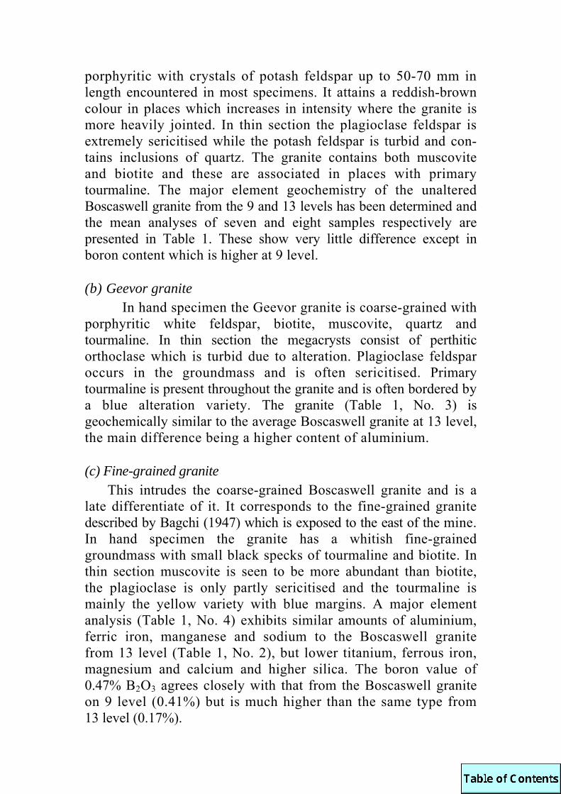
porphyritic with crystals of potash feldspar up to 50-70 mm in length encountered in most specimens. It attains a reddish-brown colour in places which increases in intensity where the granite is more heavily jointed. In thin section the plagioclase feldspar is extremely sericitised while the potash feldspar is turbid and con-tains inclusions of quartz. The granite contains both muscovite and biotite and these are associated in places with primary tourmaline. The major element geochemistry of the unaltered Boscaswell granite from the 9 and 13 levels has been determined and the mean analyses of seven and eight samples respectively are presented in Table 1. These show very little difference except in boron content which is higher at 9 level.
(b) Geevor granite In hand specimen the Geevor granite is coarse-grained with
porphyritic white feldspar, biotite, muscovite, quartz and tourmaline. In thin section the megacrysts consist of perthitic orthoclase which is turbid due to alteration. Plagioclase feldspar occurs in the groundmass and is often sericitised. Primary tourmaline is present throughout the granite and is often bordered by a blue alteration variety. The granite (Table 1, No. 3) is geochemically similar to the average Boscaswell granite at 13 level, the main difference being a higher content of aluminium.
(c) Fine-grained granite This intrudes the coarse-grained Boscaswell granite and is a
late differentiate of it. It corresponds to the fine-grained granite described by Bagchi (1947) which is exposed to the east of the mine. In hand specimen the granite has a whitish fine-grained groundmass with small black specks of tourmaline and biotite. In thin section muscovite is seen to be more abundant than biotite, the plagioclase is only partly sericitised and the tourmaline is mainly the yellow variety with blue margins. A major element analysis (Table 1, No. 4) exhibits similar amounts of aluminium, ferric iron, manganese and sodium to the Boscaswell granite from 13 level (Table 1, No. 2), but lower titanium, ferrous iron, magnesium and calcium and higher silica. The boron value of 0.47% B2O3 agrees closely with that from the Boscaswell granite on 9 level (0.41%) but is much higher than the same type from 13 level (0.17%).
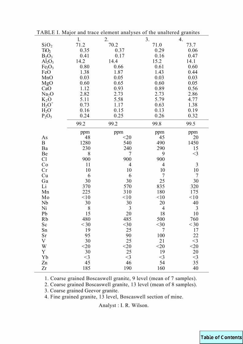
TABLE I. Major and trace element analyses of the unaltered granites l. 2. 3. 4.
SiO2 71.2 70.2 71.0 73.7 TiO2 0.35 0.37 0.29 0.06 B2O3 0.41 0.17 0.16 0.47 Al2O3 14.2 14.4 15.2 14.1 Fe2O3 0.80 0.66 0.61 0.60 FeO 1.38 1.87 1.43 0.44 MnO 0.03 0.05 0.03 0.03 MgO 0.60 0.65 0.60 0.05 CaO 1.12 0.93 0.89 0.56 Na2O 2.82 2.73 2.73 2.86 K2O 5.11 5.58 5.79 4.77 H2O+ 0.73 1.17 0.63 1.38 H2O- 0.16 0.15 0.13 0.19 P2O5 0.24 0.25 0.26 0.32 99.2 99.2 99.8 99.5 ppm ppm ppm ppm As 48 <20 45 20 B 1280 540 490 1450 Ba 230 240 290 15 Be 8 7 9 <3 Cl 900 900 900 Co 11 4 4 3 Cr 10 10 10 10 Cu 6 6 7 7 Ga 30 30 25 30 Li 370 570 835 320 Mn 225 310 180 175 Mo <10 <10 <10 <10 Nb 30 30 20 40 Ni 8 3 4 3 Pb 15 20 18 10 Rb 480 485 500 760 Sc < 30 <30 <30 < 30 Sn 19 25 7 17 Sr 95 90 100 22 V 30 25 21 <3 W <20 <20 <20 <20 Y 30 25 19 20 Yb <3 <3 <3 <3 Zn 45 46 54 35 Zr 185 190 160 40
1. Coarse grained Boscaswell granite, 9 level (mean of 7 samples). 2. Coarse grained Boscaswell granite, 13 level (mean of 8 samples). 3. Coarse grained Geevor granite. 4. Fine grained granite, 13 level, Boscaswell section of mine.
Analyst : I. R. Wilson.

There are many local varieties of granite, especially in the killas-granite contact areas (Garnett 1962) ; most are coarse grained porphyritic varieties with similar geochemistry to the Boscaswell and Geevor types.
3. Trace element geochemistry of the unaltered granites The granites considered above have been analysed for a wide
range of trace elements and these are also presented in Table 1. Particular features of the coarse-grained Boscaswell and Geevor granites are the high contents of boron, lithium, rubidium and tin compared to a published average for low-calcium granites (Turekian and Wedepohl 1961). It has been pointed out by Tauson (1967) that in intrusives with high contents of volatiles the elements with a strong affinity for volatiles become concen-trated in the upper parts of the intrusives (eg. Li, Rb, Sn, W and Nb) and particularly in late differentiates. The later fine-grained-granite is particularly enriched in B, Rb, and Nb compared to the Boscaswell granite from 13 level. It is, however, markedly depleted in barium and strontium a feature suggestive of a well fractionated granite. In all the granites tin exceeds the published average value of 3 ppm (Turekian and Wedepohl 1961) and this is a feature common to many other Cornish granites (Hall 1971). Boron exhibits a marked increase above the average value of 10 ppm (ibid.) and may have been enriched by both fractional crystallisation of the magma and by post-magmatic alteration. This does not fully explain the high values and it is possible that the granites have been produced by partial melting of sediments with a high boron content.
4. Geochemical and mineralogical variations in wall-rock (a) Alteration in the vicinity of Sinuns lode
Apparently unaltered granites, removed from visible alteration, all exhibit some degree of alteration in thin section with sodic plagioclase being partially replaced by sericite. Towards the lode, the wall-rock exhibits a slightly red appearance due to haematite discolouration, which generally becomes more intense adjacent to the lode. This zone of reddening or haematisation may be as much as 3-6 m wide, but at the sampling points is 2 m wide on 9 level and 1 m wide on 13 level. In the outer zone of reddening the plagioclase is almost completely sericitised and is often replaced by quartz and potassic feldspar. The nature
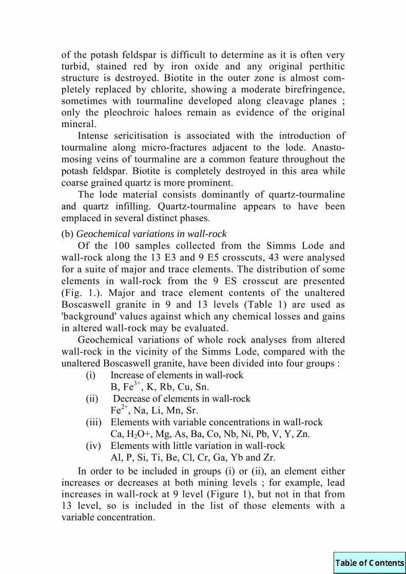
of the potash feldspar is difficult to determine as it is often very turbid, stained red by iron oxide and any original perthitic structure is destroyed. Biotite in the outer zone is almost com-pletely replaced by chlorite, showing a moderate birefringence, sometimes with tourmaline developed along cleavage planes ; only the pleochroic haloes remain as evidence of the original mineral.
Intense sericitisation is associated with the introduction of tourmaline along micro-fractures adjacent to the lode. Anasto-mosing veins of tourmaline are a common feature throughout the potash feldspar. Biotite is completely destroyed in this area while coarse grained quartz is more prominent.
The lode material consists dominantly of quartz-tourmaline and quartz infilling. Quartz-tourmaline appears to have been emplaced in several distinct phases. (b) Geochemical variations in wall-rock
Of the 100 samples collected from the Simms Lode and wall-rock along the 13 E3 and 9 E5 crosscuts, 43 were analysed for a suite of major and trace elements. The distribution of some elements in wall-rock from the 9 ES crosscut are presented (Fig. 1.). Major and trace element contents of the unaltered Boscaswell granite in 9 and 13 levels (Table 1) are used as 'background' values against which any chemical losses and gains in altered wall-rock may be evaluated.
Geochemical variations of whole rock analyses from altered wall-rock in the vicinity of the Simms Lode, compared with the unaltered Boscaswell granite, have been divided into four groups :
(i) Increase of elements in wall-rock B, Fe3+, K, Rb, Cu, Sn. (ii) Decrease of elements in wall-rock Fe2+, Na, Li, Mn, Sr. (iii) Elements with variable concentrations in wall-rock Ca, H2O+, Mg, As, Ba, Co, Nb, Ni, Pb, V, Y, Zn. (iv) Elements with little variation in wall-rock Al, P, Si, Ti, Be, Cl, Cr, Ga, Yb and Zr.
In order to be included in groups (i) or (ii), an element either increases or decreases at both mining levels ; for example, lead increases in wall-rock at 9 level (Figure 1), but not in that from 13 level, so is included in the list of those elements with a variable concentration.
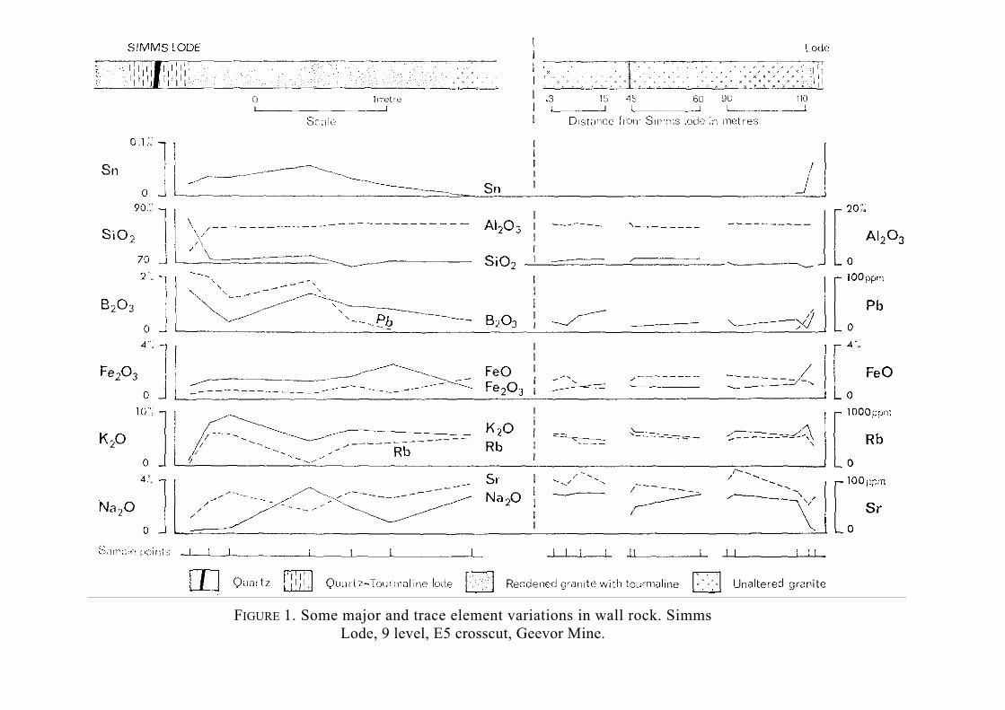
FIGURE 1. Some major and trace element variations in wall rock. Simms
Lode, 9 level, E5 crosscut, Geevor Mine.

As tourmalinisation is the main type of wall-rock alteration occurring in both levels it is not surprising that the boron increases towards the lode. Reddening of the granite is associated with the increase in ferric iron, while the higher potassium content is due to a residual enrichment of potash feldspar following removal of sodium from the system. Losses in ferrous iron are attributed to biotite being destroyed in the wall-rock. The distribution of tin, present as cassiterite, in the wall-rocks coincides with the limit of visible alteration, 2 m from the lode at 9 level (Figure 1). Tin has a significant correlation with boron as these two elements exhibit a consistent dispersion pattern in tourmalinised wall-rock.
It is generally found in the mine that there are numerous minor fractures between major lode systems. The extent of alteration and geochemical variations around minor fractures is very limited and rarely exhibits high tin values, though the alteration products are, on a smaller scale, similar to those around the larger economic lodes.
A detailed description of the behaviour of each element is given elsewhere (Wilson 1972).
5. Alteration Processes Probably the most important process of metasomatism in wall-
rock alteration is mineral hydrolysis, or hydrogen metasomatism, where hydrogen ions are added to the rock and the base metal cations are released. Various mineral and alteration assemblages have been recorded and detailed chemical analyses made of wall-rocks from Simms Lode and various minor fractures, but little has been written about the reaction of silicate rocks with the mineralising solutions. Chemical reactions are presented by Hemley and Jones (1964) and Meyer and Hemley (1967) many involving simple hydrolytic decomposition, or hydrogen metaso-matism, of the silicates. Some of those reactions pertinent to the study are given below in simplified form, they may have taken place simultaneously or over a long period of time.
(a) Plagioclase replaced by sericite plagioclase + 2H+ + K+ → sericite + Na+ + Ca2
+ 3SiO2 (quartz) (b) Plagioclase partly replaced by kaolin
plagioclase + 4H+ + 2H2O → kaolinite + 4SiO2 + 2Na+ + Ca2+

(c) Potash feldspar partly replaced by K-mica and quartz orthoclase + 2H+ → sericite + 2K+ + 6SiO2 (quartz)
(d) biotite partially replaced by chlorite biotite + 4H+ → chlorite + (Mg.Fe)2+ + 2K+ + 3SiO2
In order to evaluate chemical gains and losses the results of the wall-rock analyses were calculated in gram equivalents. The results can be further modified by multiplying the weight per cent by the density of the rock assuming a constant total volume. If one considers the principal cations involved in metasomatism, especially magnesium, sodium, potassium and calcium, the wall-rocks exhibit a small overall net loss of base. Minor fractures show a net loss similar to wall-rock adjacent to the main Simms Lode. However, despite the marked mineralogical changes that have taken place, there have been few overall chemical gains and losses ; in general a chemical balance has been maintained during the alteration processes. It also suggests that hydrogen metaso-matism is an important process in wall-rock alteration studies.
6. Conclusions The practicality of using trace elements as a guide to new
lodes in Geevor Mine is limited as the dispersion patterns are very restricted and do not extend beyond the zones of visible mineralogical alteration. This conclusion is based on the results of analyses from several lodes and diamond drill holes. Geochemical analyses during a prospecting programme would be superfluous as the altered material, within perhaps 3 m of a lode, is obvious and nothing would be gained by analysis. It is hoped, however, that the information obtained in this study will add to the basic data concerning the distribution of trace elements adjacent to mineralisation, and may help to stimulate further geochemical research upon wall-rock alteration. ACKNOWLEDGEMENTS. The work was undertaken as part of Ph.D. research programme at the University of Leeds under the supervision of Dr. G. Hornung, to whom the author is indebted for advice and encouragement. Thanks are offered to the Mine Manager and staff of Geevor Tin Mines Ltd., for their help. BAGCHI, T. C., 1947. Geology of Land's End Granite. PH.D.THESIS,
UNIVERSITY OF LONDON. BRADSHAW, P. M. D. and A. J. STOYEL, 1968. Exploration for blind
orebodies in southwest England by the use of geochemistry and fluid inclusions. TRANS.INSTN.MIN. METALL. (Sect. B: Appl. earth sci.), Vol. 77: B144-152.
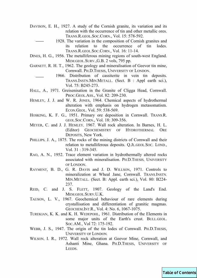
DAVISON, E. H., 1927. A study of the Cornish granite, its variation and its relation with the occurrence of tin and other metallic ores. TRANS.R.GEOL.SOC.CORN., Vol. 15: 578-592.
1928. The variation in the composition of Cornish granites and its relation to the occurrence of tin lodes. TRANS.R.GEOL.SOC.CORN., Vol. 16: 11-14.
DINES, H. G., 1956. The metalliferous mining regions of south-west England. MEM.GEOL.SURV.,G.B. 2 vols, 795 pp.
GARNETT, R. H. T., 1962. The geology and mineralisation of Geevor tin mine, Cornwall. PH.D.THESIS, UNIVERSITY OF LONDON.
1966. Distribution of cassiterite in vein tin deposits. TRANS.INSTN.MIN.METALL. (Sect. B : Appl earth sci.), Vol. 75: B245-273.
HALL, A., 1971. Greisenisation in the Granite of Cligga Head, Cornwall. PROC.GEOL.ASS., Vol. 82: 209-230.
HEMLEY, J. J. and W. R. JONES, 1964. Chemical aspects of hydrothermal alteration with emphasis on hydrogen metasomatism. ECON.GEOL. Vol. 59: 538-569.
HOSKING, K. F. G., 1951. Primary ore deposition in Cornwall. TRANS.R. GEOL.SOC.CORN., Vol. 18: 309-356.
MEYER, C. and J. J. HEMLEY, 1967. Wall rock alteration. In Barnes, H. L. (Editor) GEOCHEMISTRY OF HYDROTHERMAL ORE DEPOSITS, New York.
PHILLIPS, J. A., 1875. The rocks of the mining districts of Cornwall and their relation to metalliferous deposits. Q.JL.GEOL.SOC. LOND., Vol. 31 : 319-345.
RAO, A. N., 1952. Trace element variation in hydrothermally altered rocks associated with mineralisation. PH.D.THESIS, UNIVERSITY OF LONDON.
RAYMENT, B. D., G. R. DAVIS and J. D. WILLSON, 1971. Controls to mineralization at Wheal Jane, Cornwall. TRANS.INSTN. MIN.METALL. (Sect. B: Appl. earth sci.), Vol. 80: B224-237.
REID, C. and J. S. FLETT, 1907. Geology of the Land's End. MEM.GEOL.SURV.U.K.
TAUSON, L. V., 1967. Geochemical behaviour of rare elements during crystallisation and differentiation of granitic magmas. GEOCHEM.INT.R., Vol. 4: No. 6, 1067-1075.
TUREKIAN, K. K. and K. H. WEDEPOHL, 1961. Distribution of the Elements in some major units of the Earth's crust. BULL.GEOL. SOC.AM., Vol 72: 175-192.
WEBB, J. S., 1947. The origin of the tin lodes of Cornwall. PH.D.THESIS, UNIVERSITY OF LONDON.
WILSON, I. R., 1972. Wall rock alteration at Geevor Mine, Cornwall, and Ashanti Mine, Ghana. PH.D.THESIS, UNIVERSITY OF LEEDS.

GYPSUM IN THE PERRAN IRON LODE, CORNWALL
by S. Henley The Perran Iron Lode occurs in a brecciated belt up to 30 m
wide, trending ESE from the north Cornish coast at Gravelhill (SW 763575). It is mineralised for much of its known length of over 6 km, and contains siderite, pyrite. sphalerite, galena, and a number of less important iron, lead, zinc, and silver minerals, listed by Collins (1874) and Dines (1956). The carbonates and sulphides have been oxidised to depths of up to 80 m, the siderite and pyrite being altered to limonite and hematite. It is certain (Sabine 1968) that the alteration took place at only slightly elevated temperatures, perhaps of the order of 46+°C Collins (1874), and that sulphuric acid attained high concentrations in the solutions resulting from oxidation of the sulphides.
At Gravelhill Mine, the lode outcrops near sea level, and relatively unaltered carbonate and sulphide ore are exposed in the cliffs. A thin layer (up to 1 mm) of iron oxide coats the siderite and pyrite, and embedded in this are minute (1-2 mm) needles of a colourless mineral, apparently monoclinic under the hand lens. Similar, but much larger (up to 20 mm) colourless needles occur in the interiors of dumps at Duchy Peru Mine some 3 km inland. They are embedded in limonitic coatings, up to 10 mm thick, which surround many rock and ore fragments. X-ray diffraction study (Table 1) has shown that the needles are gypsum, and thus provide striking evidence of the concentration of sulphate ions during oxidation of dump materials. Abundant white clay, interstitial between ore fragments in the dumps, suggests similarity with the alteration processes at Treamble Mine described by Sabine (1968), and indicates the very short geological time in which the kaolinisation at Treamble could have taken place.
The presence of gypsum in the Duchy Peru dump raises the problem of the source of the calcium. Although ankerite has been reported from Mount Mine (Dines 1956) and hedenbergite from Great Retallack Mine (Collins 1874 ; Henley 1971) calcium is generally very low in minerals of the Perran Lode and in the slate wall rocks (Guppy and Sabine 1956 ; Henley 1970). However,

the dunes of Gear Sands to the west contain a large amount of comminuted shell fragments. It seems likely that over the 85 years since the cessation of mining, sufficient fine calcareous sand has been transported by the wind to account for the observed calcium in the dumps. This may explain the presence of gypsum in the lode outcrop at Gravelhill for it is directly overlain by dune sand. During surface oxidation of the ores, sulphuric acid has reacted with any overlying sand grains, and gypsum has crystallised in the limonitic crust while any remaining calcium carbonate has since blown away.
TABLE 1. X-ray diffraction powder patterns of colourless, monoclinic, acicular crystals in ilmonitic weathering crust from the Perran Iron Lode, and a standard (ASTM card 6-0046).
Nottingham University Film 683 ASTM gypsum ; card 6-0046. d (Å) Intensity d (Å) Intensity 7.53 vs 7.56 100 4.25 vvs 4.27 51 3.79 w 3.79 21 3.35 w 3.06 vvs 3.059 57 2.86 s 2.867 27 2.786 5 2.68 s 2.679 28 2.51 vw 2.495 6 2.46 vw 2.22 w 2.216 6 2.08 m 2.080 10 2.073 8 1.896 w 1.898 16 1.867 w 1.879 10 1.805 w 1.812 10 1.775 w 1.778 10 1.684 1 1.671 vw 1.664 4 1.653 vw 1.645 2 1.615 vw 1.621 6

COLLINS, J. H., 1874. On the Great Perran Iron Lode. REP.MINERS ASS.
CORN.DEVON (1873): 55. DINES, H. G., 1956. The Metalliferous Mining Region of South-west
England, MEM.GEOL.SURV.U.K. GUPPY, E. M, and P. A. SABINE, 1956. Chemical analyses of igneous rocks,
metamorphic rocks, and minerals. MEM.GEOL.SURV.U.K. HENLEY, S., 1970. The geology and geochemistry of an area around
Perranporth, Cornwall. PH.D.THESIS, UNIVERSITY OF NOTTINGHAM.
1971. Hedenbergite and sphalerite from the Perran Iron Lode, Cornwall. PROC.USSHER SOC., Vol. 2: 329-334.
SABINE, P. A., 1968. Origin and age of solutions causing the wallrock alteration of the Perran Iron Lode, Cornwall. TRANS. INSTN.MIN.METALL., Vol. 77: B1-5.
Hydraulic fracturing in south Pembrokeshire and north-west Devon (Abstract) : by Paul L. Hancock.
Hydraulic fracturing occurs when an abnormally high pore-fluid pressure exceeds the least principal stress by an amount equal to, or greater than, the tensile strength of a rock. During the deposition of the Old Red Sandstone in Pembrokeshire and the Upper Carboniferous in Devon high pore-fluid pressures were developed as a consequence of relatively rapid rates of sedimentary strain. By minimising the frictional resistance to sliding, the high fluid pressure enabled flexural-slip folds to form serially at a rapid strain-rate, thus further increasing the fluid pressure.
In both regions the two principal categories of hydraulic fracture are early-formed fracture cleavage. together with kindred barren structures, and younger quartz or carbonate veins. The fracture cleavage was developed after the fold in which it occurs but before later compressional structures, such as thrusts and shear zones. The fluid responsible for fracturing was probably derived from the cleaved bed and its immediate neighbours. The quartz or carbonate veins, which are mainly at a high angle to the bedding and cleavage, were probably initiated by high pressure fluids coming from more distant sources. It is possible that the increase in permeability which would follow cleavage formation enabled this fluid migration to occur.

OBLIQUE FOLDING IN SOUTH-WEST ENGLAND
by David J. Sanderson Abstract. Anomalous fold axial patterns from South-west England are examined in the light of quantitative models of oblique folding proposed by Sanderson (1972). The nature and extent of oblique folding are related to observed strain states determined independently from deformed objects.
The dominant attitude of the axes of early folds throughout Cornwall and Devon is sub-horizontal and trending E-W to NE-SW. Locally, however, fold axes may diverge from this attitude and in these places the folds are termed 'oblique.' Quantitative models have been described by Sanderson (1972) by which original populations of fold axes, subparallel to the intermediate principal strain axis (the Y-axis of the finite strain ellipsoid), may become passively rotated by homogeneous strain to form various patterns of oblique folds. Using the equations for the resulting frequency distributions of oblique folds derived from this study, the anomalous attitudes of fold axes in parts of South-west England have been investigated.
In north Cornwall the recumbent primary folds generally have axes trending ENE-WSW, but on the coast from Boscastle to south of Tintagel the axes are variable with many trending N-S (Dearman et al. 1964). Using the oblique fold models to generate theoretical frequency distributions, the observed fold axis pattern can be simulated from an original Gaussian distribution with a standard deviation of 20° and a mean at 5° to the Y-axis by stretching parallel to the axial plane of the folds (Fig. la). The original standard deviation of the axes is of the same order as that observed from the ENE trending folds to the north and south of the oblique fold zone (Sanderson 1972, table I). A strong stretching lineation is developed throughout the area of oblique folding as indicated by the deformation of the agglomerates in the Tintagel Volcanic Group (Hobson 1971), the stretched Spirifers in the Upper Devonian slates and the alignment of chlorite and pyrite within slaty cleavage. Quantitative evaluation of the strain indicators may be used as a comparison with values of X/ Y obtained from model simulation.
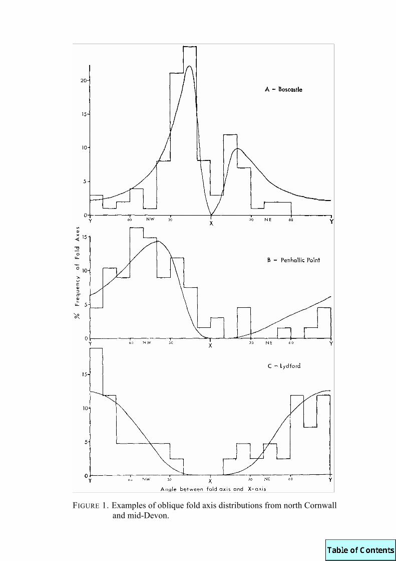
FIGURE 1. Examples of oblique fold axis distributions from north Cornwall
and mid-Devon.

Stretched Spirifers at Hole Beach (SW 050874) give X/ Y= 2 and the same value is indicated by a fit of the observed and simulated oblique fold axes (Fig. lb). The volcanic agglomerate pebbles give X/Y = 2-3 but insufficient fold axes and bedding/ slaty cleavage lineations can be measured in this lithology to permit comparison with model distributions. No reliable strain indicators exist in the black slates and the Boscastle beds, although they have a strong mineral lineation and the pyrite shows ellipsoidal sections in the slaty cleavage with axial ratios of about 4. The distribution of fold axes from Boscastle indicates X/Y = 5 (Fig. la) which is higher than that given by the volcanic pebbles, but, at Trebarwith Strand, an increase in strain ratio towards the black slates has been found. This suggests that the black slates took up most of the deformation, a fact clearly seen during F~ folding. Hence it is suggested that X/Y = 5 is not an unreasonable estimate for this lithology.
The zone of oblique folding may be traced from its coastal exposure in the Tintagel area inland to the western margins of Dartmoor (Dearman 1969) where it is considerably wider and has lower X/Y ratios as illustrated by the F, axial distribution at Lydford (Fig. lc).
Dearman (1969) also recognised a zone of oblique folding (his tergiversate folding) along the south Cornwall coast (Fig. 2a). Here, comparison of observed and simulated fold axis distributions indicate X/ Y values of between 2 and 3 (Fig. 2b). Strain indicators are rare in the rocks of this area, but at Pendower Beach (SW9038) concretions and pebbles in fine conglomerates show axial ratios of 2.5 to 3 (Fig. 2c) which correspond closely with X/Y = 3 obtained from an analysis of the fold axis distribution.
This summary of the oblique folding in South-west England shows that there is close agreement between the observed dis-tributions of fold axes and those calculated from model studies (Sanderson 1972) and that the value of X/Y determined from the models is similar to the value obtained from observed strain indicators, where such comparisons can be made. The location of oblique folding, as outlined by Dearman (1969, fig. 2), can now be interpreted as representing two zones of intense deformation, one located between Tintagel and Dartmoor, the other along the south coast of Cornwall.

FIGURE 2 (a) Distribution of zones of oblique folding in S.W. England. (b) Histogram of oblique fold axis distribution, Pendower Beach,
south Cornwall. (c) Strain data from deformed concretions and pebbles at
Pendower Beach.

DEARMAN, W. R., E. C. FRESHNEY and M. C. MCKEOWN, 1964. Early folds and the α-lineation at Tintagel, Cornwall. NATURE LOND., Vol. 203: 933-35.
1969. Tergiversate folds from South-west England. PROC. USSHER SOC., Vol. 2: 112-15.
HOBSON, D. M., 1971. Deformed agglomerates near Tintagel, North Cornwall. GEOL.MAG., Vol. 108: 383-91.
SANDERSON, D. J., 1972. The development of fold axes oblique to the regional trend. TECTONOPHYSICS (in press).
THE TERTIARY STRUCTURE OF THE HALDON HILLS by R. J. O. Hamblin
Abstract. A plan of spot-heights for the base of the Haldon Gravels is compiled from field mapping and seismic survey, and reveals shallow tectonic structures. An east-west orientated syncline on Little Haldon and the south end of Great Haldon is correlated with the downwarping of the Bovey Basin. Further north, periclinal structures represent the tightening of pre-Senonian folds known in the Upper Greensand. Faults cutting the Gravels are considered to be of Eocene or Oligocene age.
1. Introduction The Haldon Hills comprise an elongated plateau remnant
between the valleys of the Teign and Exe, capped by Haldon Gravels overlying Upper Greensand and Permian breccias. The Haldon Gravels comprise Eocene residual and fluvial gravels and Pleistocene head.
As part of the resurvey of the Teignmouth (339) sheet for the Institute of Geological Sciences, the whole area has been mapped on a 1: 10560 scale and a seismic survey of the plateau carrried out, allowing the compilation of detailed levels for the base of the Haldon Gravels and the Upper Greensand. Details of the seismic techniques used and of the folding revealed in the Upper Greensand are already published (Durrance and Hamblin 1969), but more gentle folds can also be detected in the base of the Haldon Gravels. Obviously great care must be taken when examining minor undulations in poorly consolidated sediments, but after considering the possibility of lowering of the Gravels by solifluc-tion, cambering, differential compaction or washing out of the Greensand, certain structures remain which can only be interpreted by gentle tectonism.
FIGURE 1. Plan of spot heights, in metres, for the base of the Eocene Haldon Gravels. All the Tertiary faults cutting the Gravels are shown, also the 700ft (213.4m) and 800ft (243.8m) topographic contours.

Figure 1 shows heights for the base of the Gravels, also all faults cutting the Gravels. Figure 2 shows the heights after the removal of the effects of faulting, using as a datum the level of the base in the outlier west of Ashcombe ; this technique is permissible as the faulting is known in detail, and is desirable in view of the gentle nature of the folding.
2. Tertiary Folding On Little Haldon the base of the Gravels dips northwards
from 237 to 215 m, paralleling that of the Greensand and roughly paralleling that of the Permian to the west, thus suggesting a tectonic tilt. In the outlier west of Ashcombe, residual gravel lies at a low level (227-228m), and the base rises in the areas east of Harcombe and north of Ashcombe to around 250 m, indicating overall an east-west synclinal fold. Compared to the larger basin structure detected in the base of the Greensand (Durrance and Hamblin 1969, fig. 4) this fold has slightly greater area, but a lower amplitude, 35m compared to 60m.
Mapping of the Bovey Basin by Dr. R. A. Edwards (1970) has revealed Upper Greensand below 90m O.D., overlain by Eocene gravels, which dip westward below the Bovey Formation. No significant faulting is known to account for this, and it is suggested that the downfolding on Haldon is related to the tectonic subsidence which formed the Bovey Basin. Such an origin is in accord with the nature of the fold, the absence of an anticlinal counterpart to the north of the syncline argues that the mechanism of folding is one of polar subsidence rather than free-folding due to north-south compression as in the case of the pre-Senonian folding (Durrance and Hamblin 1969). Since the fold affects all the Eocene Haldon Gravels, and the Bovey Beds formed within the Basin during the Middle Oligocene (Chandler 1957), this folding would be of late Eocene or early Oligocene age.
The high levels of 250m for the base of the Gravels at Kenton Hill (909816) and east of Zigzag Wood (920806) are surrounded by Gravels at lower levels, and between them the base drops to 233m. As the Eocene Gravels here are fluvial such variations in height could reflect differential downcutting into the Greensand, but no evidence of such erosion has been found ; a tectonic origin is preferred in view of the shape and distribution of the

FIGURE 2. Plan of contours and spot heights, in metres, for the base of the Eocene Haldon Gravels, adjusted by the removal of the effects of faulting, using as a datum the outlier west of Ashcombe. Synclinal axes in the base of the Greensand are shown, taken from Durrance and Hamblin (1969) figure 4.

structures, as the relative position of high and low values coincide well with the periclinal folding known in the base of the Greensand in this area (Durrance and Hamblin 1969). The base of the gravels follows the form of two small periclinal domes, orientated ENE-WSW and these coincide with high levels for the base of the Greensand, thus it is considered that the structures represent tightening of the pre-Senonian folds in Eocene or later times.
Some 2.Skm SE of Underdown is a narrow basin structure some 20m deep. There is no possibility here of fluvial channelling as the Eocene gravels are residual deposits formed by solution of Chalk in situ, and solifluction effects may be discounted as the base of Gravels dips into the hill on the flanks of the basin on all sides. This basin corresponds well with a minor basin in the base of the Greensand and again represents the tightening of earlier folds. It is noted that whereas all the minor structures found in the base of the Greensand were periclinal basins, a basin and two domes are recognised in the base of the Gravels.
3. Tertiary Faulting
Figure 1 shows all major faults cutting the Gravels, excepting certain structures considered to represent a recent gravity slide (Durrance and Hamblin, 1969). Furthest north are two major faults with throws of around 20m, and hereabouts at least four more minor structures were detected in seismic lines ; these are considered to be of Eocene age, related to local tectonic adjustment during formation of the Haldon Gravels (Durrance and Hamblin 1969: 81). Throughout the remainder of Great Haldon the faults appear to form a pattern ; with one obvious exception they trend NNW-SSE and NNE-SSW ; all are high-angle dip-slip faults, with throws of the order of 5 to 11m, and no consistency in their direction of throw. They join with acute angles to the north and south, suggesting that they may be fundamentally tear faults formed by compressive stress from the north and south (Anderson 1951), so possibly they are rejuvenated Hercynian structures. All beds present are faulted, up to late Eocene age, so it is suggested that they form a system of accommodation fractures contemporary to the folding which formed the Bovey Basin, ie late Eocene or early Oligocene.

ANDERSON, E. M., 1951. THE DYNAMICS OF FAULTING AND DYKE FORMATION WITH APPLICATIONS TO BRITAIN. 2nd edn., Edinburgh and London.
CHANDLER, M. E. J., 1957. The Oligocene flora of the Bovey Tracey lake basin, Devonshire. BULL.BR.MUS.(NAT.HIST.) GEOL., Vol. 31 : 73-123.
DURRANCE, E. M. and R. J. O. HAMBLIN, 1969. The Cretaceous structure of Great Haldon, Devon. BULL.GEOL.SURV.GR.BR., No. 30 : 71-88.
EDWARDS, R. A., 1970. The geology of the Bovey Basin. PH.D.THESIS, UNIVERSITY OF EXETER.
THE FORM OF THE PERMO-TRIASSIC BASIN IN SOUTH-EAST DEVON
by M. R. Henson
Abstract. The results of a seismic reflection and refraction survey show the form of the Permo-Triassic basin in this area to be typical of a pediment with a mountain front adjacent to the upland source area to the west, and demonstrate the relationships of the sedimentary formations occupying the basin. Mapping of the basal unconformity indicates the presence of an earlier pediment above the present basin which is shown to consist of two cuvettes.
1. Introduction For a full understanding of the depositional history of the
Permo-Trias it is important that the configuration of the basal unconformity should be known. A seismic survey was carried out by the Institute of Geological Sciences in cooperation with the Department of Geology, University of Exeter, to prove the depth and form of the Permo-Triassic basin in the area covered by Sheet 339 (Teignmouth). The results also indicate depths to discontinuities in the Permo-Trias that may be identified with the mapped formations. The mapping of the western margin of the Permian outcrop shows the form of the unconformity adjacent to the upland source area in considerable detail.
Initially it was hoped to obtain a profile from the Haldon Hills to Colaton Raleigh by continuous profile reflection shooting. However shot holes at least 9 m deep were required to overcome

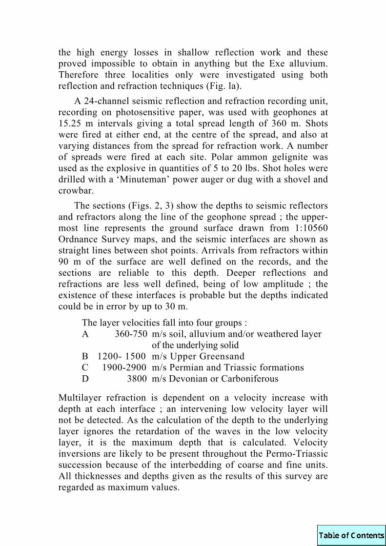
the high energy losses in shallow reflection work and these proved impossible to obtain in anything but the Exe alluvium. Therefore three localities only were investigated using both reflection and refraction techniques (Fig. la).
A 24-channel seismic reflection and refraction recording unit, recording on photosensitive paper, was used with geophones at 15.25 m intervals giving a total spread length of 360 m. Shots were fired at either end, at the centre of the spread, and also at varying distances from the spread for refraction work. A number of spreads were fired at each site. Polar ammon gelignite was used as the explosive in quantities of 5 to 20 lbs. Shot holes were drilled with a ‘Minuteman’ power auger or dug with a shovel and crowbar.
The sections (Figs. 2, 3) show the depths to seismic reflectors and refractors along the line of the geophone spread ; the upper-most line represents the ground surface drawn from 1:10560 Ordnance Survey maps, and the seismic interfaces are shown as straight lines between shot points. Arrivals from refractors within 90 m of the surface are well defined on the records, and the sections are reliable to this depth. Deeper reflections and refractions are less well defined, being of low amplitude ; the existence of these interfaces is probable but the depths indicated could be in error by up to 30 m.
The layer velocities fall into four groups : A 360-750 m/s soil, alluvium and/or weathered layer
of the underlying solid B 1200- 1500 m/s Upper Greensand C 1900-2900 m/s Permian and Triassic formations D 3800 m/s Devonian or Carboniferous
Multilayer refraction is dependent on a velocity increase with depth at each interface ; an intervening low velocity layer will not be detected. As the calculation of the depth to the underlying layer ignores the retardation of the waves in the low velocity layer, it is the maximum depth that is calculated. Velocity inversions are likely to be present throughout the Permo-Triassic succession because of the interbedding of coarse and fine units. All thicknesses and depths given as the results of this survey are regarded as maximum values.

The nature of the records suggests that the interfaces recorded are the major velocity contrasts in the succession, and therefore correspond to boundaries between the formations mapped on the basis of their lithology (Henson 1970, 1971). The sections are interpreted on the basis of two main criteria: (a) that the seismic refractors or reflectors arise from the major interfaces in the succession corresponding to the formation boundaries, and (b) that individual layers (formations) will have a small range of trans-mission velocities. Depths are in metres above or below Ordnance Datum.
2. Seismic refraction and reflection survey, interpretation
(a) Marsh Plantation, Great Haldon (Spreads 1-3), Figure 2a
The low velocity layer, 1200-1500 m/s, is identified as the Upper Greensand overlying the Teignmouth Breccias, velocity 2500-2900 m/s. The velocities accord reasonably well with those obtained by Durrance and Hamblin (1969): 1280-1680 m/s for the Upper Greensand and 2800-3000 m/ s for the Teignmouth Breccias. In constructing the section the Haldon Gravels have been disregarded. Beneath the Upper Greensand the Permian surface is a gentle anticline that is cut by two faults of opposite throw. The western fault is the larger with a downthrow of 18 m to the east and was recognised by Durrance and Hamblin ; the eastern fault has a throw of 11 m to the west. The form and elevation of the sub-Greensand surface are close to that shown by Durrance and Hamblin (1969, Fig. 3). Thicknesses of Upper Greensand preserved are 68 m between the faults, 48 m to the west and 41 m to the east. An insignificant reflection within the Teignmouth Breccias was recorded at one shot point. A well-defined reflection was recorded at +67 m; probably arising from the base of the Permian. Deeper reflecting horizons were recorded from the other localities, proving that the absence of deeper reflections is due to the absence of reflecting horizons rather than the inability of the instruments to detect them. An absence of reflections is to be expected from the underlying Palaeozoic because of its intense folding. The Permian at this point is 109 ± 30 m thick.
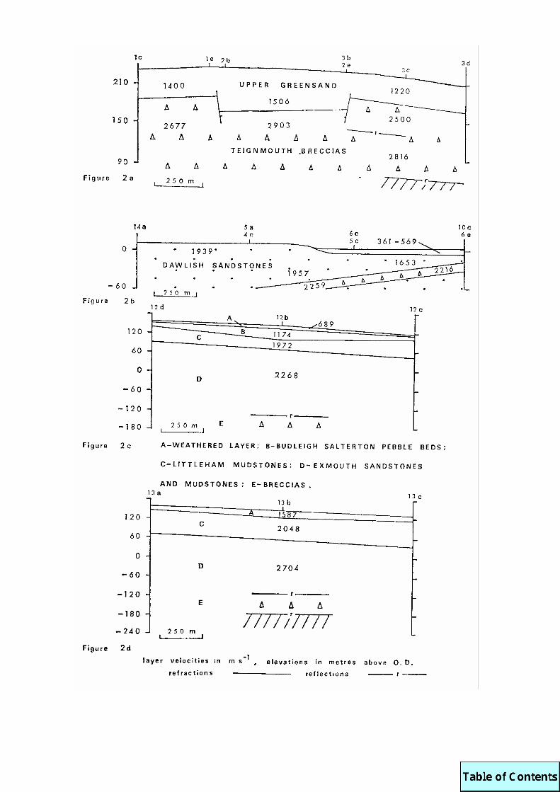

(b) Powderham (Spreads 4-6), Figure 2b A layer of alluvium up to 9 m thick, velocity 360-570 m/s,
overlies the solid. Red coarse and medium-grained sand was recovered from holes drilled west of the alluvium, and aeolian sand is exposed in a small pit 200 m to the north-west. The layer immediately under the alluvium is therefore interpreted as aeolian sand of the Dawlish Sandstones, with a velocity of 1650-1939 m/s. A refractor, velocity 2240 m/s, was recorded at shot points 5-6. The same refractor recurred at shot point 10 in the intersecting spread, above a layer of the same velocity as the aeolian sand. The refractor has a velocity approaching those of the Teignmouth Breccias and is most likely one of the breccia units that are present within the Dawlish Sandstones. It dips north-west and apparently dies out a little to the north. Gentle folding of the Permian on approrimately east-west axes is probably present in this area, though no indication of its form or scale can be gained from the results of this survey.
(c) Powderham (Spreads 8-10), Figure 3 Alluvium with a maximum thickness of 10 m, velocity 660-
780 m/ s, forms the surface layer for the length of this spread. The solid layer beneath is characterised by the same velocities as the Dawlish Sandstones in spreads 4-6, with the same impersistent breccia unit. A layer of velocity 2600 m/ s underlies the sandstones at - 125 m. The interface is encountered at almost all the shot points and appears to dip to the north-north-west. As the trans-mission velocity is within the range of those obtained for the

Teignmouth Breccias on Great Haldon, the layer is interpreted as Teignmouth Breccias. An interface giving rise to both refractions and reflections was recorded at - 182 ± 30 m. The velocity, 3800 m/s, is in excess of any recorded from the Permian and Triassic but accords with those from Devonian slates and limestones underlying the Teign estuary (Durrance 1971). This high velocity layer is therefore interpreted as Palaeozoic and the interface as the base of the Permian. At this point the Permian is 176 ±30 m thick. (d) Exton (Spread 7)
A single spread was fired here and the velocity of the Exmouth Sandstones and Mudstones determined ; no reflections or refractions were obtained from the underlying layers. If the Exmouth Formation is assumed to rest on the Palaeozoic then its calculated minimum thickness is 52 m. If thicknesses of 40, 60, and 50 m are estimated for the Exe Breccias, Dawlish Sandstones and Teignmouth Breccias respectively, the thickness of the Permo-Triassic here is about 210 m and the basin floor is at - 195 m.
(e) Colaton Raleigh (Spread 12), Figure 2c A thin discontinuous layer of weathered material overlies the
unweathered Budleigh Salterton Pebble Beds. The Pebble Beds have a low velocity, 1174 m/ s, probably due to their coarse-grained, unconsolidated nature. The maximum thickness of the Pebble Beds is 35 m ; the irregular form of their base, when con-sidered with the results of resistivity surveys (Henson 1971, Sherrell 1970) suggests gentle folding. Two layers of slightly differing velocities underlie the Pebble Beds. It would seem unlikely that their interface is the base of the Littleham Mudstones. If the refraction is taken as the base, then the thickness of the formation is very much less than that obtained from the mapping and the results of spread 13 ; the refracting horizon could be one of the thick silty sand horizons that are occasionally present in the formation.
(f) Colaton Raleigh (Spread 13), Figure 2d The spread lies within an inlier of the Littleham Mudstones. A
10m thick layer of Pebble Beds debris and weathered Littleham Mudstones, velocity 1587 m/s, overlies the solid. The velocity of the top solid layer is similar to those interpreted as Littleham Mudstones (spread 12). The layer beneath shows a marked

velocity increase and it is considered that the higher velocity, 2700 m/s, is characteristic of the Exmouth Sandstones and Mudstones whilst the lower velocity, 2000 m/s, is characteristic of the Littleham Mudstones.
A reflection was recorded at - 130 ±30 m, the same depth as the lowest recorded interface of spread 12. The coincidence of this interface suggests that it is a well marked horizon, probably the unconformity at the base of the Exmouth Sandstones and Mudstones where they overlie sands and breccias. The lower reflection at - 180 ± 30 m could arise from velocity contrasts within the breccias or from the discontinuity at the interface with the Palaeozoic. It is tentatively identified as the base of the Permo-Triassic basin. It is possible, however, that this lowest reflection could arise from lavas intercalated in the basal members of the breccias, if this is so the base of the Permian would be a little deeper than indicated.
From the section the Permo-Trias at this point is 330 ±30 m thick and the floor of the basin is at -180 ± 30 m.
3. Basin Profile The base of the Permo-Trias was proved with certainty only at
Powderham and on Great Haldon ; on Colaton Raleigh Common a reflection was interpreted as arising from the velocity contrast at the base. At Exton the estimated position of the base is close to values obtained at the other localities. The interpretations are the simplest explanations of the observed layer pattern and it is considered that they are a reasonable representation of the structure. The heights of the base of the Permo-Trias and the form of the formation boundaries are drawn as a profile across the basin through the areas investigated (Fig. lb).
The base is a concave upwards surface rising steeply in the west and flattening to the east. This surface form is typical of a pediment, formed by the weathering of a highland area by erosion concentrated at the foot of the uplands (Leopold et al. 1964). Characterised by a sharp break in slope where the pediment meets the mountain front, the profile is typical of weathering in arid and semi-arid climates.

There is no evidence to support the existence of a large fault along the line of the Exe, previously invoked (Godwin-Austin 1842, Murchison 1867) as controlling the form of the lower Exe Valley and explaining the apparent discontinuity at the Exe between the breccias to the west and the sandstones and mudstones to the east. D. J. C. Laming (pers. comm.) considers that the postulated fault would have a throw of 300 m; a dislocation of such magnitude would be clearly revealed on an aeromagnetic map ; however, no anomaly is indicated (Aeromagnetic Map of Great Britain, Sheet 2). The major anomaly in this area is linked to the mountain front at the western margin of the basin, to the east the aeromagnetic map indicates a gradually deepening sedimentary basin with no marked irregularities. Any faults present in the succession, either beneath the Exe or elsewhere, are of limited magnitude (up to 20 m).
The Permo-Triassic succession in this area is composed of breccias and sands (Marginal Deposits) deposited by alluvial fans as a piedmont fan adjacent to the mountain front. Overlying these, are sandstones and mudstones (Fluvial Basin Deposits), probably Triassic in age, deposited as a flood plain complex with a different source area to the underlying Permian beds (Laming 1966 ; Henson 1970, 1971).
The breccias and sands of the Marginal Deposits clearly thin towards the deeper parts of the basin and away from the mountain front. It is likely that further to the east the piedmont fan complex deposits become altogether absent. In that case the flood plain complex would rest directly on the Palaeozoic forming the basin floor. From the profile it is clear that the flood plain sediments cannot be the fine-grained lateral equivalents of the alluvial fans. They form a separate distinct phase in the infilling of the basin. There is insufficient evidence to indicate precisely the form of the formations in the Fluvial Basin Deposits but it is probable that they will thicken to the east.
Mapping of the basal Permo-Triassic unconformity north of Bishopsteignton (Hamblin 1969) shows it to be horizontal in the west but dipping to the east in the east. The seismic survey shows that the unconformity has an easterly dip of at least 12° and is a typical mountain front. The horizontal unconformity and the lower, mountain front, erosion surface can be explained by

invoking two erosion cycles producing pediments. The horizontal surface is the remains of a late Carboniferous pediment developed across the Teign Valley towards Dartmoor, the low summits of the Teign Valley being remnants of this surface ; this was originally postulated by Lowe (1903). The lower pediment is that infilled by late Stephanian and Permo-Triassic deposits demonstrated by the seismic survey ; the deposits of the early cycle would have been an easily eroded source for the materials of the later cycle.
The unconformity at the mouth of the Teign estuary is a planar surface dipping gently east ; around Bishopsteignton and Netherton it shows a marked change in attitude dipping steeply to the south, suggesting a ridge formed of the mountain front extending into the depositional basin. South of the Teign the mountain front swings sharply to the west and it is evident that the unconformity shows considerable relief ; the basal members of the breccias infilling relict valleys. The ridge at Bishopsteignton forms a divide between two depositional cuvettes in which accumu-lated two contrasting but laterally equivalent breccia sequences, i.e., Teignmouth Breccias and the Oddicombe, Netherton and Watcombe Breccias. In the area south of the Teign there is no evidence of the upper erosion surface.
4. Conclusions
Mapping and the results of the seismic survey indicate the presence of two erosion cycles, of which the later is infilled by the relatively thin Permo-Triassic succession. The seismic survey shows that the Permo-Triassic basin has the form typical of a pediment with a mountain front to the west. There is no evidence for a large fault along the line of the Exe estuary. The piedmont fan complex of the Marginal Deposits thins eastwards towards the main basin area and is over-stepped by the Fluvial Basin Deposits that thicken eastward towards the main basin area. The sandstones and mudstones of the Fluvial Basin Deposits, flood plain sediments, are clearly not the fine-grained lateral equivalents of the alluvial fans.
Transmission velocities and thicknesses were calculated for each of the formations recognised in the survey as follows.

velocity thickness (m/s) (m)
Upper Greensand ... ... 1400 40-60 Budleigh Salterton Pebble Beds ... 1174 35 Littleham Mudstones ... ... 2000 88 Exmouth Sandstones and Mudstones ... 2700 165 Dawlish Sandstones ... ... 2000 100 Teignmouth Breccias ... ... 2700 113 Palaeozoic (Devonian/Carboniferous) ... 3800
ACKNOWLEDGEMENTS. The work was carried out as part of the N.E.R.C. contract with the University of Exeter for the revision of the Teignmouth (339) Sheet. Thanks are due to Dr. D. Masson-Smith and Mr. G. P. Riddler, of the I.G.S., and Mr. E. M. Durrance, Exeter University, who directed and carried out the seismic survey ; also to Mr. Durrance and Professor S. Simpson for helpful discussions on the interpretation.
DURRANCE, E. M., and R. J. O. HAMBLIN, 1969. The Cretaceous structure of Great Haldon, Devon. BULL.GEOL.SURV.U.K., No. 30 : 71-88.
1971. The buried channel of the Teign estuary. PROC.USSHER SOC., Vol. 2: 299-306.
GODWIN-AUSTIN, R. A. C., 1842. On the geology of Southeast Devonshire. TRANS.GEOL.SOC.LOND. Ser. 2, vol 6, pt. 2: 433-489.
HAMBLIN, R. J. O., 1969. The geology of the Haldon Hills. PH.D.THESIS, UNIVERSITY OF EXETER.
HENSON, M. R., 1970. The Triassic rocks of South Devon. PROC.USSHER SOC. Vol. 2: 172-177.
1971. The Permo-Triassic rocks of South Devon. PH.D. THESIS, UNIVERSITY OF EXETER.
LAMING, D. J. C., 1966. Imbrications, palaeocurrents and other sedimentary features in the Lower New Red Sandstone, Devonshire, England. J.SEDIM.PETROL., Vol. 36: 940-959.
LEOPOLD, L. B., M. G. WOLMAN and J. P. MILLER, 1964. FLUVIAL PROCESSES IN GEOMORPHOLOGY. SAN FRANCISCO, 522 pp.
LOWE, H. J., 1903. The Teign valley and its geological problems. REP.TRANS.DEVON.ASS.ADVMT.SCI., Vol. 25: 631-645..
MURCHISON, R. I., 1867. SILURIA, LONDON. SHERRELL, F. W., 1970. Some aspects of the Triassic aquifer in east
Devon and west Somerset. Q.JL.ENG.GEOL., Vol. 2: 255-286.
This contribution is published by permission of the Director, Institute of Geological Sciences.

PROVINCIAL AFFINITIES OF EIFELIAN PHACOPIDS
(TRILOBITA) OF SOUTH WEST ENGLAND AND BRITTANY
by C. J. Burton
Abstract. European Eifelian phacopid trilobites show marked provinciality, based mainly on geographical grounds, the two proposed provinces being separated by a land barrier. The different morphological groups of phacopids inhabiting the separate provinces are described. The two provinces (North-Central and Southern European) and the separate morphological groups overlap in South West England and Brittany, making the region valuable for phacopid comparisons and correlations.
1. Introduction A comparison of the Eifelian phacopid trilobites of South
West England with those from other parts of Europe reveals that they most resemble species occurring in Brittany. Moreover phacopids from this Armorican (South West England - Brittany) region can be divided into three morphologically distinct groups which are concomitant within the region. All other European Eifelian phacopids can be divided into the same three groups, but, except in Czechoslovakia, the groups do not coexist, each being restricted to a particular area. In this paper the author describes these morphological groups and discusses why they occur together in the Armorican region, and the importance of this in deciding between facies dependent groupings and provincial groupings in phacopids.
Nomenclature. The terms used in this paper to describe the trilobites follow the usage of the Treatise on Invertebrate Paleontology Part O, Arthropoda 1 (R. C. Moore ed., 1969), except where specifically indicated.
2. Trilobite groups The Armorican phacopids, and those of Europe in general, are here divided into three morphological groups. The species mentioned are the Armorican representatives of the groups. Group 1, (Fig. la). Phacops schlotheimi ssp. nov., Phacops schlotheitni (Bronn), and Phacops brongniarti (Steininger). The cephalic outline is narrow, with the genal angles being always

FIGURE 1. The morphological grouping of European phacopid trilobites : a, Group 1; b, Group 2; c, Group 3. (Reconstructions typical of each group).

lobate and rearward-pointing. The glabella is always high and has a steep anterior slope and flattish top. The intercalating ring (preoccipital glabellar lobe, Treatise : 125) is always low, or degenerated into three lobes, with the intercalating furrow (2p) arched forward and shallow centrally. The glabellar ornament is always prominent, and lateral glabellar furrows are never visible. The palpebral lobes are always strongly rounded and there are never lateral ridges to the rear of the eyes. The genae are smooth, except for their tuberculate posterior margins, and bear no marginal rims. The eyes are always large and have vertical or near vertical visual surfaces.
Members of this group are common in the Middle Devonian of Poland, Czechoslovakia, Germany, Belgium and the Armorican region, (Burton 1969) but are rare in Southern Europe.
Group 2, (Fig. lb). Phacops oehlerti Morzadec. Massively built trilobites with a wide cephalon, the genal angles are gently rounded and do not point rearwards. The glabella is high and flat topped but has a rounded anterior profile. The intercalating ring is massive and complete ; the intercalating furrow is also complete, and deeply incised lateral glabellar furrows are present. The glabellar tubercles are numerous but not large. Strong ridges exist to the rear of the eyes, and the richly ornamented genae have marginal rims. The eyes are small and set forward.
Members of this group are very common in Czechoslovakia (Bohemian Basin), Southern Europe, Asia Minor and Brittany, but are not recorded in South West England, North France, Belgium or Germany. Group 3, (Fig. lc). Phacops batracheus Whidborne (Givetian - see later) and Phacops cf sp. A, B, C, fecundus degener Morzadec. The cephalic outline is always greater than a semicircle and the genal angles gently rounded. The glabella is low and wide and has a rounded anterior slope. The intercalating ring is complete and as high as the occipital ring, the intercalating furrow is discontinuous. Lateral glabellar furrows are visible. The glabellar ornament is low, close-packed and small. The palpebral lobes are usually flat and cushion-like and there are small ridges behind the eyes. The genae are weakly ornamented and the marginal rims poorly developed. The eyes are long and strip-like with sloping visual surfaces.

Members of this group have a much wider range than those of Group 2 being locally common in the Bohemian Basin, and also occurring in Moravia, Southern Europe, Asia Minor, North West Africa and the Armorican area (Morzadec 1969a, Burton 1969). They are not recorded in North France and Belgium, and rarely in Germany.
This group, although distinct, is related morphologically to Group 2, sharing the same general cephalic shape, lateral glabellar furrows, ridges behind the eyes and marginal rims. There is some evidence from Asia Minor that Group 3 may have evolved from Group 2, there being a stratigraphic series of species leading from one group to the other (Haas 1968, P1.30, figs. 6-8). The Group 3 phacopids also appear to be identical to the subgenus Phacops (Chotecops) Chlupác, 1971, erected after this present study began (Chlupác, 1971).
3. Facies and Provinces The distribution of the three groups could be limited by
facies, or by geographical barriers. However the adherence of particular groups of Eifelian phacopids to facies appears to vary considerably from area to area. The Group 1 Armorican phacopids usually occur in shales and dark lenticular or nodular limestones ; a lithology which together with the associated brachiopod and cephalopod faunas suggest the Mixed Magnafacies of Erben (1964). Some coeval phacopids of this group from Belgium, Germany and Poland also share this Magnafacies, others may be found in crinoidal limestones of the Hercynian Magnafacies. The Group 2 Armorican phacopids also occur in the Mixed Magnafacies, (Morzadec 1969a) whereas all other coeval members of the group appear to be closely restricted to certain intra-facies of the Hercy-nian Magnafacies. The Armorican Group 3 phacopids are again all of the Mixed Magnafacies, whereas other European members are equally common in both Mixed and Hercynian Magnafacies (Chlupac pers. comm.). Thus facies limitation appears to be a local ecological response which cannot be expected to persist unchanged over wide areas, and this does not entirely explain the distribution of the three morphological groups. A provincial model is necessary to complete the explanation.

FIGURE 2. Eifelian palaeogeography of western and central Europe, and
distribution of phacopid groups.
On this basis two main areas can be established. The first area (Fig. 2), the North-Central European area, lies to the north of the Franco-Alemannian Island (Palaeogeography after Erben 1964, and others) and formed a seaway extending from South West England to Germany, Poland and Czechoslovakia (Bohemian Basin, Moravia). The second area, the Southern European area includes South West England, Brittany, the Montagne Noire, the Pyrenees and Czechoslovakia (Bohemian Basin). It may also include areas further south and east. In the central parts of these two areas phacopids were able to evolve in relative isolation and Group 1 became morphologically distinct from Groups 2 and 3. For Group I this may well have been a case of allopatric speciation. Group 2 being the most strongly facies restricted may well have developed in relative isolation from Group 3 which was less dependent on facies. However the Armorican area, like Czechoslovakia, is situated at a point where all three groups could mingle because of a lack of geographical barriers, and where, uniquely, they share a single Magnafacies and sometimes even a

single bed. Hence the Armorican area is a critical one, for only here can the North-Central and Southern European phacopid faunas be compared and correlated.
The further possibility that provinciality may have persisted in time is indicated by the Group 3 form Phacops (?Chotecops) batracheus which occurs in Givetian limestones of the Hercynian Magnafacies Almost identical forms are known from the Montagne Noire and Asia Minor, but not from North-Central Europe.
House (1971) has emphasised the distinction between the lack of provinciality in Devonian ammonoids and the suggested provinciality in fixed forms such as brachiopods and corals. The phacopids appear to occupy a median position showing evidence of large-scale provinciality among the mobile benthos.
ACKNOWLEDGEMENTS. The author's thanks are due to Dr. E. B. Selwood, Exeter University, Dr. P. Morzadec, Universite de Rennes, and Dr. I. Chlupác, Geological Survey of Czechoslovakia, for discussion and material.
BURTON, C. J., 1969. Variation studies of some phacopid trilobites of Eurasia and North West Africa. PHD.THESIS, UNIVERSITY OF EXETER.
CHLUPÁC, L, 1971. New phacopid trilobites from the Devonian of Czechoslovakia. CASOPIS MINER.GEOL., Vol. 16: 255-261.
ERBEN, H. K., 1964. Facies development in the marine Devonian of the Old World. PROC.USSHER.SOC., Vol. 1: 92-118.
HAAS, W., 1968. Trilobiten aus dem Silur und Devon von Bithynian (NW-Türkei). PALAEONTOGRAPHICA Abt. A, Vol. 130: 60-207.
HOUSE, M. R., 1971. Devonian faunal distributions. In Middlemiss F. A. and P. F. Rawson (Eds.). FAUNAL PROVINCES IN SPACE AND TIME. GEOLOGICAL JOURNAL SPECIAL ISSUE No. 4: 77-94.
MORZADEC, P., 1969a. Le Dévonian de la rive nord de la rivière du Faou (Finistère). Etude stratigraphique - Etude des trilobites. BULL.SOC.GEOL.MINER.BRETAGNE : 1-58.
1969b. Révision de Phacops (Phacops) potieri Bayle, 1878 (Trilobites). BULL.SOC.GEOL.FRANCE, (7), Vol. 11 : 917-924.

THE UPPER CARBONIFEROUS STRATIGRAPHY OF NORTH CORNWALL AND WEST DEVON
by E. C. Freshney and R. T. Taylor
Abstract. A detailed examination of the entire coastline from Northcott Mouth (North Cornwall) to Hartland Point and Clovelly (West Devon) has enabled the compilation of a stratigraphical succession for the Namurian and Westphalian sediments of the area. A structural and stratigraphical profile of the coastal section from Northcott Mouth to Hartland Point is presented. Key nodular and fossiliferous shale horizons are named and the conditions of sedimentation discussed.
1. Introduction As part of the I.G.S. primary six inches to one mile geological
survey of the Bideford and Bude (292 and 307/8) sheets a study has been made of the stratigraphy and structure displayed in the cliffs between Bude and Hartland Point. Continuous overlapping photography of the cliffs was carried out from a boat, and after measurement of key sections on the ground and applying scale corrections the photographs were used to construct a horizontal cross-section for some 21 km of coast (Plate 1).
Certain fossiliferous nodular shales, such as the Gastrioceras listeri horizon, were used in correlation, together with other per-sistent shales containing calcareous nodules. The nodular shales have been given names from coastal outcrop localities. Some slumped beds were sufficiently continuous to be of value in establishing the continuity of successions locally, but thick sand-stones were normally too impersistent for correlative purposes. The generalised successions for various parts of the coast are shown in Plate 2.
References to coastal localities in the text are given by four-figure National Grid northings, the castings being superfluous on the north-south coastline.
2. Main features of the coastal successions The stratigraphy of the Bude Formation erected by King (1966,
1971) can be tentatively followed northwards from Northcott Mouth [0855], with the occurrence of shales with nodules, one at

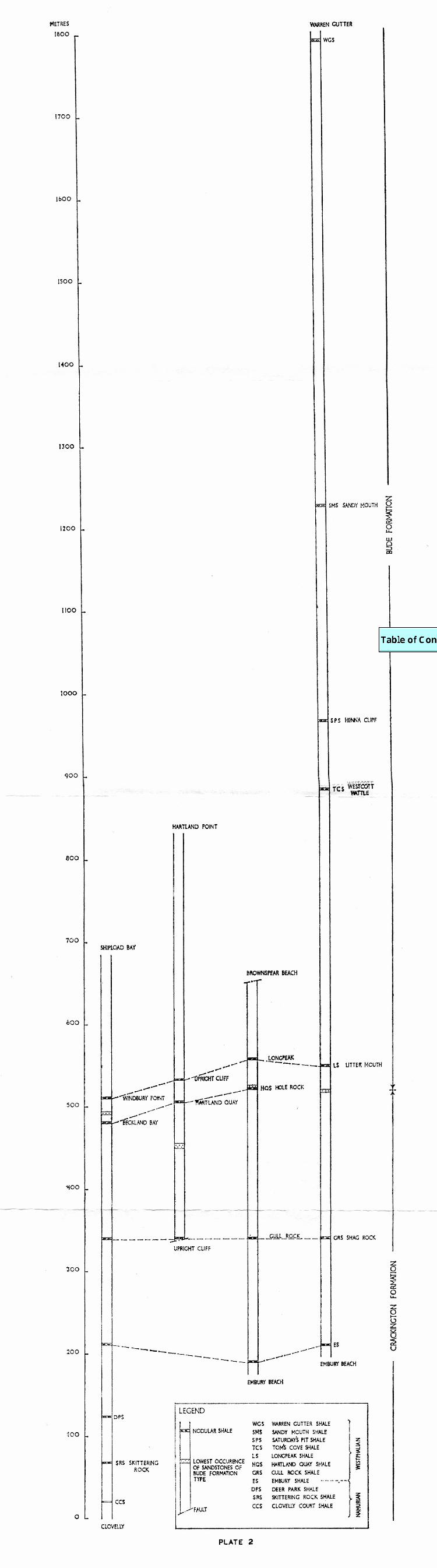

Curtis's Rock [0860] and another at Westpark Pit [0898], approximately the same distance apart as King's Tom's Cove Shale and Saturday's Pit Shale. The succession is more complete, however, there being an almost unbroken sequence from the uppermost stage of the Namurian to a shale with nodules 687 m above the top of King's succession. Sandstones of Bude Formation type have been found to occur both above and below the limits of the Bude Formation as defined by King 1971. The boundary between the Crackington Formation and the overlying Bude Formation is here placed at the base of the Hartland Quay Shale (see below).
The succession youngs northward from the Saturday's Pit Shale, the Sandy Mouth Shale being encountered about 150 m higher at Sandy Mouth [1002]. The stratigraphical position assigned to the Sandy Mouth Shale in this paper conflicts with the palaeontological evidence given by Ramsbottom (1970) who correlated it with the Margam marine band of South Wales which overlies the Gastrioceras listeri horizon. In the highest part of the succession the Warren Gutter Shale occupies the core of a synclinorial belt trending east-west through Duckpool [1150]. To the north of this axis a rapid descent through the succession takes place, resulting in the reappearance of the Sandy Mouth Shale between Lower Sharpnose [1273] and Stanbury Mouth [1345]. The descent through the succession is less rapid to the north of Stanbury Mouth, and the Tom's Cove Shale and Saturday's Pit Shale occur, and are repeated many times by folding north of Higher Sharpnose. Farther north and lower in the succession the Longpeak shale is exposed in the cliffs [1695] to the south of Marsland Mouth, although the Hartland Quay Shale, normally about 30 m below the Longpeak Shale in the Hartland area, has not been traced. Both these shales are lacking in the Bude area, where the succession is truncated by faulting 350 m below the Tom's Cove Shale. The sequence in the Marsh-land Mouth-Welcombe Mouth [1805] section of cliffs is obscured by north-west to south-east wrench faults and repetitive folding. However, there appears to be little change in stratigraphical level between Gull Rock, just south of Marsland Mouth, and the cliffs north of Welcombe Mouth. At the top of the cliffs about 200 m north of Welcombe Mouth a small exposure of black shale with nodules probably correlates with the Hartland Quay Shale or

possibly with the Longpeak Shale. Approximately 180 m below this horizon at Shag Rock [1900], there occurs the Gull Rock shale, containing nodules with Gastrioceras circumnodosum, a goniatite indicative of the well-known Gastrioceras listeri horizon. The Gull Rock Shale is underlain by 128 m of black mudstones, shales and thin turbidite sandstones, which are the Black Mud-stone Beds of Moore (1968) and resemble the strata at Wanson Mouth named Wanson Beds by Mackintosh (1964). The Embury Shale at Ramtor Rock [1965] lies near the core of a large anticline with a steep northerly limb and yields Gastrioceras subcrenatum. The Gull Rock Shale is reintroduced on the northern limb of the anticline at Gull Rock Beach [2010]. To the north of the anticline is a shallow synclinorial belt, rather complicated by faulting. In this synclinorium, at Sandhole Rock [2087], two nodular shale bands are thought to be the Longpeak and Hartland Quay Shales. The two shales are closer together than in their occurrences farther north, but the lower of the two contains the same fauna of crushed anthracoceratids which characterises the Hartland Quay Shale to the north, and it is possible that the succession of thin sandstones and thick silty shales separating the Longpeak and Hartland Quay Shales to the north has thinned southwards.
After the reappearance of the Gull Rock Shale in an anticline in the cliff at Elmscott Gutter [2153] and in anticlines on the fore-shore to the north and south of Mansley Rock [2197], the Hartland Quay and Longpeak Shales occur at Hole Rock [2262] and Longpeak Beach [2280] respectively, 185 m and 220 m above it. These two shales are repeated by east-west normal faults with southerly downthrows at Brownspear Beach [2285] just south of Spekes Mill Mouth and by folding in the cliffs between Upright Cliff [2703] and Hartland Quay. A large east-west normal fault in Upright Cliff brings up the Gull Rock Shale in the core of a major anticline to the north of the fault. The steep northern limb of the anticline brings in a further repetition of the Hartland Quay and Longpeak Shales. The succession continues upward to the core of a syncline at Hartland Point, but does not reach as high as the Saturday's Pit Shale.
The lowest part of the Upper Carboniferous sequence in the area is not found on the Bude-Hartland coast, but occurs in a periclinorial structure on the coast to the north-west of Clovelly. This section contains a complete succession from the Longpeak

Shale downwards and extends for 210 m below the Embury Shale. The Deer Park and Skittering Rock Shales contain poorly preserved goniatite faunas probably representing the G1 Gastrioceras cancellatum and Gastrioceras cumbriense horizons respectively and the Clovelly Court Shale has yielded goniatites suggesting the R2 Donetzoceras sigma horizon. The succession from Shipload Bay to Clovelly is compared with the west coast succession in Plate 2.
3. Review of the formational nomenclature The establishment of a stratigraphical succession has shown
that the massive sandstones and other lithologies which characterise the Bude Formation to the south occur as low as the Hartland Quay Shale. Since the strata equivalent to the turbiditic beds below the Gull Rock Shale have been included in the Crackington Formation on the south side of the synclinorium, it is reasonable to do the same in the north, the rocks being closely similar. Some 180 m of turbidite sandstones and shales between the Hartland Quay Shale and the Gull Rock Shale, hitherto referred to as the Welcombe Measures or Welcombe Beds and estimated to be 620 m thick by Moore (1968), are indistinguishable lithologically from the turbiditic sandstones of Namurian age below the Embury Shale. It is, therefore, proposed to classify all the dominantly turbidite sandstone-mudstone sequences of Namurian and basal Westphalian rocks as Crackington Formation. This follows the practice on the southern side of the synclinorium (Edmonds and others 1968) The name Bude Formation is used for the younger Westphalian deposits which, while they still contain sequences of turbidites, have within them substantial numbers of massive sandstones and other associated facies characteristic of the rocks described by King (1966) and Williams (in Freshney and others 1972). The base of the Bude Formation may be slightly diachronous, but a somewhat arbitrary base has been taken at the bottom of the Hartland Quay Shale, as it is above this shale that massive sandstones of Bude Formation type become progressively more common. It is realised that the Hartland Quay Shale will not be easily found inland, but the structural complexity of the area renders the accurate mapping of formational boundaries impossible in any case and the practice of mapping the Bude Formation boundary at the first occurrence of massive sandstones of Bude Formation type should give a close approximation.

4. Comments on the conditions and controls of sedimentation The bulk of the sediments from the base of the Crackington
Formation to the known top of the Bude Formation near Duckpool consists of turbiditic sandstones interspersed with grey mudstones. Below G1 the marine fauna of goniatites tends to be spread through the shales and even occurs in the bases of sandstones, thus suggesting that these beds were deposited in a dominantly marine environment. In and above G1, however, the goniatites occur exclusively within bands of black shales with nodules. In some of the higher shales, such as the Longpeak and Warren Gutter Shales, goniatites are either absent or are only present as spat, although fish remains and coprolites are commonly present. It is thought, therefore, that these upper turbidites were deposited in non-marine, possibly brackish, waters, while the fossiliferous shales represent more dominantly marine incursions. It is in these higher parts of the sequence that other facies appear among the turbidites, including the massive apparently structureless Bude Formation sandstones above the Hartland Quay Shale and also the flaggy sandstones and siltstones carrying xiphosurid tracks.
The Bude Formation has been the subject of some controversy, particularly as to the depth of water in which it was deposited. King (1965) suggested a shallow-water origin, while Burne (1970) opted for their being deeper-water turbidites or underflows. Goldring and Seilacher (1971) stated that "it would seem likely that the Bude Sandstones were deposited in a large though probably not very deep non-marine sea and away from the margin of the body of water." As Goldring and Seilacher also pointed out, the current velocity must have been so low that the limulid tracks were not scoured and they inferred from this that the sedimentation took place at a distance from the margin of the basin. However, the presence of internal structures such as cross-bedding with forsets several tens of centimetres long within the more massive Bude Sandstones indicates fairly strong current conditions, probably in or in the vicinity of a delta. This view is supported by the initial results of work on the particle size dis-tributions of the sandstones, which are similar to those of fluviatile or deltaic sediments. The differing conditions of sedimentation found in close association are not irreconcilable, it being possible to envisage a shallow non-marine basin with shifting spurs of deltaic material being introduced from a delta complex to the north.

The probable correlation of part of the Bideford Group (de Raaf, Reading and Walker 1965) with the lowest part of the Bude Formation is indicated by the presence of goniatites similar to those in the Hartland Quay Shale, in an horizon at the base of cycle 3 of the Abbotsham Formation. The Bideford Group contains subaerial delta-top facies and subaqueous topset facies and this leads to the probability that the Bude Formation was laid down partly in the outermost regions of the delta-top complex and partly at the delta-front, the more obvious turbidites being deposited beyond the front of the delta. Current-direction studies carried out by Ashwin (1957) indicate that the currents came mainly from between north-west and north-east, which is con-sistent with deltas building out from a northerly source. The current directions in the Crackington Formation below the Hartland Quay Shale, however, show a dominantly east-west pattern, similar to that found in the Crackington Formation of the Okehampton Sheet, the Holsworthy Sheet, and the Boscastle Sheet. These directions were presumably produced by axial-flow turbidity currents flowing along a trough aligned east-west, parallel to the main structural trend in the Carboniferous strata. It is possible that the change from deposition is a deep-water marine basin to deposition in shallow water with deltas encroaching from the north was brought about by the closing up of the basin by contemporaneous structural events. The presence of abundant ‘slumped’ beds in the Bude Formation tends to suggest that some structural instability initiated the movement of sediments on the delta slopes. The occurrence of goniatites and goniatite spat in some of the black shales within the Bude Formation indicates that the basin was not permanently disconnected from the sea and on occasions marine incursions took place causing a retreat of the deltas and their associated sediments to the north and the establishment of relatively quiet water conditions in the north Cornwall-north Devon area.
The apparent absence of the Gastrioceras listeri horizon in the Westward Ho! Formation of Walker (1970) would seem to indicate that the sedimentary pile has thickened in this region and that the G. listeri horizon passes beneath it, to reappear in typical turbidite sediments in the Instow area (Prentice 1960). This would imply that there was a large downwarp under the main part of the delta complex analogous to that which occurs

under the Mississippi delta. The major east-west fault mentioned by Burne and Moore (1971: 296), and proved inland along the northern part of the Chulmleigh Sheet, throws several hundred metres down to the north. Such a fault, which almost certainly affected the basement, may well have played a part in accom-modating the downwarp.
ACKNOWLEDGEMENTS. The authors are indebted to Dr. M. A. Calver and Dr. W. H. C. Ramsbottom of the Institute of Geological Sciences, Leeds, for their identification of the goniatites from the area studied, and for their useful discussion and comment.
This paper is published by permission of the Director of the Institute of Geological Sciences.
ASHWIN, D. P., 1957. The structure and sedimentation of the Culm sediments between Boscastle and Bideford, north Devon. PH.D.THESIS, IMPERIAL COLLEGE, UNIVERSITY OF LONDON.
BURNE, R. V., 1970. The origin and significance of sand volcanoes in the Bude Formation (Cornwall). SEDIMENTOLOGY, Vol. 15: 211-28.
and L. J. MOORE, 1971. The Upper Carboniferous rocks of Devon and North Cornwall. PROC.USSHER SOC., Vol. 2: 288-98.
DE RAAF, J. F. M., H. G. READING and R. G. WALKER, 1965. Cyclic sedimentation in the Lower Westphalian of north Devon, England. Sedimentology, Vol. 4: 1-52.
EDMONDS, E. A., J. E. WRIGHT, K. E. BEER, J. R. HAWKES, M. WILLIAMS, E. C. FRESHNEY and P. J. FENNING, 1968. Geology of the country around Okehampton. MEM.GEOL.SURV.U.K.
FRESHNEY, E. C., M. C. MCKEOWN and M. WILLIAMS, 1972. Geology of the coast between Tintagel and Bude. MEM.GEOL. SURV.U.K.
GOLDRING, R. and R. SEILACHER, 1971. Limulid undertracks and their sedimentological implications. N.JB,GEOL,.PALAONT.ABH., Vol. 137: 422-442.
KING, A. F., 1965. Xiphosurid trails from the Upper Carboniferous of Bude, north Cornwall. PROC.GEOL.SOC., Vol. 1: 172-4.
1960. Structure and stratigraphy of the Upper Carboniferous Bude Sandstones, North Cornwall. PROC.USSHER SOC., Vol. 1 : 229-32.
1971. Correlation in the Upper Carboniferous Bude Formation, North Cornwall. PROC.USSHER SOC., Vol. 2 : 285-8.

MACKINTOSH, D. M., 1964. The sedimentation of the Crackington Measures. PROC.USSHER SOC., Vol. 1: 88-9.
MOORE, L. J., 1968. The stratigraphy of the Carboniferous rocks of the Hartland area of north Devon. PROC.USSHER SOC., Vol. 2 : 18-21.
PRENTICE, J. E., 1960. Dinantian, Namurian and Westphalian rocks of the district south-west of Barnstaple, north Devon. Q.JL. GEOL.SOC., Vol. 115: 216-289.
RAMSBOTTOM, W. H. C., 1970. Some British Carboniferous goniatites of the family Anthracoceratidae. BULL.GEOL.SURV.GT.BR., No. 32 : 53-60.
WALKER, R. G., 1970. Deposition of turbidites and agitated water siltstones : a study of the Upper Carboniferous Westward Ho ! Formation, North Devon. PROC.GEOL.ASS., Vol. 81 : 43-67.
THE CONODONT BIOSTRATIGRAPHY OF THE PLYMOUTH LIMESTONES ABOUT THE MIDDLE/UPPER
DEVONIAN BOUNDARY
by M. J. Orchard
Abstract. A study of the conodont faunas of the Plymouth Limestones has revealed a hitherto unexpected thickness of Upper Devonian strata. Sections which have produced diagnostic Upper Givetian and early Upper Devonian associations are described. None of these, as yet, has produced conodonts indicative of the critical Hermanni-Cristatus Zone or the succeeding lowermost Asymmetricus Zone.
1. Introduction The Plymouth Limestone Series, the westernmost of the Middle
Devonian limestone masses of S.W. England, constitutes a carbonate complex which spans most of the Middle Devonian and continues high into the Frasnian. Apart from the earlier workers (see House & Selwood 1966: 46-7), little work was done on the limestones until Taylor (1950) presented a correlative map and a structural interpretation. The sedimentology of some of the limestones was studied by Braithwaite (1967). The limestones have been widely sampled and processed in an attempt to establish a conodont succession. The results so far obtained have revealed that many of Taylor's correlations and age determinations, based on the coral fauna, can no longer be upheld.

The conodont associations indicating strata lying near to the Middle/Upper Devonian boundary are here recorded and some biostratigraphical details noted. The relevant localities will be described in stratigraphical order and some facies interpretations suggested. The standard European conodont zonation as established in the Rhenish Schiefergebirge by Ziegler (e.g. 1965, 1971) is here used.
2. The Conodont Successions (a) The Varcus Zone
The older parts of the Plymouth limestones have not produced very good faunas although the varcus Zone is well developed in the western part of the limestone block, especially at Richmond Walk (46055438). Here, the northern (oldest) beds yield the diagnostic forms Polygnathus varcus, Po.rhenanus, rare Po.webbi (i.e. lower part of the varcus Zone) and Spathognathodus brevis as well as the less important elements which compare closely with many of the bars and blades described by Bischoff & Ziegler (1957) from the varcus Zone in Germany. These limestones, which are dark and bituminous and contain in situ growths of lamellar stromatoporoids and Heliolites, also contain numerous specimens of Belodella spp. which is replaced as the dominant form by Po. linguiformis linguiforinis in the turbulent, shallower water conditions represented by the more massive bioclastic limestones of the higher horizons. To the south in this section conodont evidence is lacking except for fragments of Po.l.linguiformis but determinable forms re-appear in the fine-grained pure limestones at the southern end of the quarry where Po. varcus and Po.l.linguiformis are associated. It may be that these forms have been re-worked but the lack of other diagnostic forms precludes accurate dating.
To the west of Richmond Walk, at Mount Wise (45555405). Po. varcus is found associated with Po. linguiformis linguiformis, Po. linguiformis transversa and Po. bryanti. The two latter species were described by Wittekindt's (1966) from his "transversa Zone" (uppermost M. Devonian), though Ziegler (1971) questioned the validity of this zone, and assigned these levels to the upper part of the varcus Zone and in part to the hermanni-cristatus zone. The Mount Wise conodont fauna is associated with brachiopods which appear to occur as small lenses in what may have been a

deeper water "fore-reef" environment. The Richmond Walk debris-rich skeletal limestones to the east seem to have been at the turbulent edge of the "reef-mass," which may have extended across the Hoe to Cattedown, whsere non-productive Amphipora micrites (49555357) may represent a contemporary "back-reef" situation.
A locality at Coxside (48805384) yielded fragmentary specimens of Po. cf. rhenanus in a fauna almost wholly consisting of icriodids, a group entirely absent from Richmond Walk.
(b) Hermanni-Cristatus Zone and Lowermost Asymmetricus Zone These two zones, which mark a critical interval in conodont
zonation as it relates to the German ammonoid Stufen and the traditional Middle/Upper Devonian boundary (see Kullman and Ziegler 1970), have not, as yet, been found in Plymouth.
(c) Lower Asymmetricus Zone The lowest Upper Devonian level identified is within this zone
and is recognised in the Western King (46155329) section, at Eastern King Point and to the east in Radford Quarry. Diagnostic forms include Ancyrcdella rotundiloba rotundiloba, A. rotundiloba alata and Po. dengleri as well as the two subspecies of the nominate zonal species.
The Eastern King Point (46675346) sample includes small immature specimens of Palmatolepis transitans and may represent a slightly younger horizon since this species does not appear in the Western King sequence until higher in the succession when it is accompanied by a more diverse assemblage including Po. cf. brevis and ? Nothognathella cf. ziegleri among others, forms similar to those described from the Asymmetricus Zone of North America by Clark and Ethington (1967).
The Western King limestones are rather thin-bedded with a macrofauna of Alveolites, Thamnpora, and lamellar Stromato-poroids in a red shaly matrix containing much fine crinoidal debris. There are also local concentrations of solitary corals. These associations suggest a relatively deeper water, "fore-reef" facies, not seen at lower levels. In Radford Quarry (50515300) the limestones are dark and micritic with no recognisable macrofauna, the (red) shale component is quite large and further up the succession (which is inverted) it forms thin seams interbedded

with the limestones. The southernmost (oldest) beds contain Po. decorosa s.l. Po.asymmetricus asymmetricus, Po.dengleri A.rotundiloba rotundiloba and a profusion of icriodids.
(d) Middle Asymmetricus Zone At a slightly higher horizon in Western King (46115326) a
variety of poorly preserved palmatolepids include Pa.subrecta and indicate the Middle Asymmetricus Zone, which is similarly recognised in Durnford Street, Stonehouse (46395369), where a fauna including these palmatolepids and dominated by polygnathids of the decorosus - dubius (formerly foliatus) - pennatus group, also includes A. gigas.
BISCHOFF, G. and W. ZIEGLER, 1957. Die Conodontenchronologie des Mitteldevons und des tiefsten Oberdevons. ABH.HESS. LANDESAMPT.BODENFORSCH., Vol. 22: 1-136, pl. 1-21.
BRAITHWAITE, C. J. R., 1967. Carbonate environments in the Middle Devonian of South Devon, England. SEDIMENT, GEOL., Vol. 1 : 283-320.
CLARK, D. L. and R. L. ETHINGTON, 1967. Conodonts and zonation of the Upper Devonian in the Great Basin. MEM.GEOL.SOC.AM., 103 : 1-94, pl. 1-9.
HOUSE, M. R. and E. B. SELWOOD, 1966. Palaeozoic palaseontology in Devon and Cornwall. In Hosking, K. F. G. and G. J. Shrimpton, (Editors). PRESENT VIEWS ON SOME ASPECTS OF THE GEOLOGY OF CORNWALL AND DEVON. R.geol.Soc. Corn., Penzance : 45-86, pl. 1-4.
KULLMAN, N. J, and W. ZIEGLER, 1970. Conodonten und Goniatiten von der Grenze Mittel-/Oberdevon aus dem Profil am Martenberg (Ostrand des Rheinischen Schiefergebirges). GEOLOGICA ET PALAEOTOLOGICA Vol. 4: 73-85, 1 pl.
TAYLOR, P. W., 1950. The Plymouth Limestones ; and the Devonian tetracorals of the Plymouth Limestones. TRANS.R.GEOL. SOC.CORN., Vol. 18: 146-214.
WITTENKINDT, H., 1966. (1965) Zur Conodontenchronologic des Mittel-devons. FORTSCH.GEOL.RHEINLD.WESTF., Vol. 9: 621-646, fig. 1, table 1, pls. 1-3.
ZIEGLER, W., 1965. Eine Verfeinerung der Conodontengleiderung au der Grenze Mittel- /Oberdevon. FORTSCHR.GEOL.RHEINLD. WESTF., Vol. 9: 647-676, 6 pls.
1971. Conodont stratigraphy of the European Devonian. MEM.GEOL.SOC.AM., 127: 227-284.

THE USSHER SOCIETY
Objects To promote research into the geology and geomorphology of South West England and the surrounding marine areas; to hold Annual Conferences at, various places in South West England where those engaged in this research can meet both formally to hear original, contributions and progress reports and informally to effect personal contacts ; to publish proceedings of such Conferences or any other work which the officers of the Society may deem suitable.
Constitution Membership. A person shall become a member on written applica-
tion to the Secretary and payment of the annual subscription. Subscription The annual subscription shall be one pound fifty pence
for ordinary members and one pound for students and retired members, due on January lst each year.
Conference Fee. All those who attend a Conference shall pay fee at the time of registering, the amount of which will be determined from year to year by the Organizing Committee:
Annual Business Meeting. A business meeting shall be held during each Annual Conference and shall elect the Organizing Committee and two auditors for the next Conference.
The Organizing Committee shall consist-of a Chairman who shall hold office for not more than, two consecutive years and shall not be eligible for re-election to the office for a further two years, a Vice-Chairman, who shall be the retiring Chairman, a Secretary, a Treasurer, an Editor and five others, any of whom may be eligible for re-election. The Committee shall have powers to co-opt
Conference Guests. The Organizing Committee shall be empowered to invite a distinguished scientist, not a member of the Society, to attend an Annual Conference and address it on the topic of interest to the Society
Amendment of this Constitution may be effected by simple majority vote at the Annual Business Meeting.