the versabot manual - picaxe · versabot, the first solderless ... you will see a diagram of a...
TRANSCRIPT

The Versabot Manual
July 2009

Index
1. Getting Started 1.1 How this manual works 1.2 Breaking out your pieces
2. The Components 2.1 The Motherboard 2.2 The Modules 2.3 The Microbric ‘Brics’ 2.4 Connecting the Batteries 2.5 Joining Modules to your Motherboard using the Brics 2.6 The Download Adapter
3. Programming the Microcontroller on your Motherboard
3.1 Installing the software 3.2 Pin Numbers 3.3 Making a LED flash 3.4 Adding a slide switch 3.5 Adding a buzzer 3.6 The push button 3.7 The motor – forwards/backward 3.8 Using bump sensors 3.9 The infrared receiver
4. Building your Bump Robot 4.1 What will it do? 4.2 Putting it together 4.3 Downloading the program to drive your bump robot 4.4 The code
5. Building your Remote Control Robot 5.1 What will it do? 5.2 Putting it together 5.3 Preparing the Remote Control 5.4 Downloading the program 5.5 The code
6. What Now? 6.1 Cleaning up the edges 6.2 Variations 6.3 Go online

1. Getting Started
Finally! An electronics set that is really easy to build without sacrificing functionality! Welcome to Versabot, the first solderless construction set made for electronics enthusiasts.
1.1 How this manual works This manual will take you through the various components that you have received in your kit and how to join them together. It will describe how to use your computer to program the individual parts of your project. You will then be shown how to put a basic Bump Robot together, and how to download a program to drive it and, finally, you will see a diagram of a completed Infrared controlled robot for you to build, and download the code to drive it. In addition, you can go online to view Frequently Asked Questions, New Possibilities for construction and New Code for programming as well as finding out the latest news in Versabot electronics. If you follow the manual through from start to finish, you will learn everything you need to know to create the robots we have given you, as well as the knowledge and skills needed to build and program unique robots of your own. Additional information about programming the PICAXE microcontroller which acts as the 'brains' of your Versabot is included in the PICAXE Manuals accessible through the Programming Editor and AXEpad Help menus.
1.2 Breaking out your pieces Your kit comes with a range of pieces, shown below. A number of your pieces will have arrived within PCBs (printed circuit boards). You need to remove these pieces before you can start building your robot. Most pieces can be pushed out with your thumbs, but if you are having difficulties, use the end of your screwdriver to gently lever them out.

2. The Components
2.1 The Motherboard The Motherboard contains the 'brains' of your robot. On it you will find a PICAXE-28X2 chip, a 9-way download connector for programming your micro-controller, an on/off slide switch, Pins (edge contacts), a Power LED, and a variety of components and integrated circuits needed to connect the circuits electronically and mechanically.
2.2 The Modules Along with your motherboard you have received a range of little circuit boards that hold electromechanical devices. Each of these has a different function and when joined to the motherboard at the pins, you can program them to perform their functions. The modules consist of: LED module This module contains an LED (light emitting diode) and the
circuitry to drive it. A LED is a tiny light, used, amongst other things, to show that an electronic device is turned on.
Slide Switch module
This module contains a small switch and the circuitry to drive it. A switch allows us to turn an electronic device on, or ‘switch’ between two electronic functions.
Buzzer module
This module contains a Buzzer and the circuitry to drive it. The buzzer is able to make sounds and even play simple tunes.
Button module
This module contains a small push Button and the circuitry to drive it. It can be used to start or stop an electronic function.
Motor module This module contains a small Motor and the circuitry to drive it. The motor can be used to drive wheels forwards and backwards.
Bump Sensor module
This module contains a Bump Sensor and the circuitry to drive it. A bump sensor can detect when it touches something, such as bumping into an object.
Infrared Receiver module
This module contains an Infrared Receiver and the circuitry to drive it. An infrared receiver can pick up a signal sent using infrared light from a remote control device.
Labelled picture of the Motherboard (label parts listed to the left)

2.3 The Microbric ‘Brics’ Microbric ‘Brics’ are tiny building blocks which can be used to hold the motherboard and modules together. These tiny black pieces fit into holes along the edge of the motherboard and the modules (and other parts) and, when screws are added, complete the circuit. You will need to assemble your Brics before you can use them. To do this, fit 3 of the tiny nuts into each bric.
You can then use the Brics to attach the various modules (and other pieces) to the motherboard. When connecting modules to the motherboard you need to make sure of a few things:
1. Make sure that the little red dot on the edge of the module lines up exactly with the little red dots on the edge of the Motherboard (at the pins).
2. Make sure that you use all 3 screws and do them up firmly (but not too tight).
3. Make sure that the Bric is the right way around. It will only fit one way – you do not need to force pieces together!
2.4 Connecting the Batteries The motherboard is powered by batteries. You have been provided with four counter sunk screws that are different to all of the others (they have a flat, instead of a rounded, head), and 4 nuts. Use these to attach the holder to the underside of the motherboard, making sure that the gold battery contact pads are aligned with the slots in the blue battery mounts and the wires from the battery holders. (See the diagram below). The kit requires 6 AAA batteries. Put these in before flicking the switch to power up your motherboard. Once it is turned on, check that the tiny red power LED is lit up – this will indicate that you have put it together correctly. If it doesn’t light up, check that your batteries are all in the right way and that they are pushed in firmly before rechecking your assembly.

2.5 Joining Modules to your Motherboard using the Brics The modules are joined to the motherboard using Brics. You connect each module at a Pin. The pins are written around the outside edge of the motherboard as P0, P1, P2 etc. Let’s try connecting a module:
1. Find a LED module, from your module collection. 2. Line up the red dot on your LED module with the red dot on the Motherboard at P0 (Pin 0). 3. Now fit a Microbric into the holes on the edge of your LED module
NOTE: The tiny pins on the Bric fit into the holes if you put the Bric in the wrong way, the bric will sit crooked, i.e.
However, if you turn it up the other way it will sit straight. i.e.
4. Fit the Bric into the holes at P0 on the motherboard. 5. Now screw in three screws firmly to complete the connection. If you’ve done it correctly, your Module and Motherboard should look like this:
2.6 The Download Adapter Your Versabot is provided with a 9-way to 3.5mm Jack socket adapter for downloading. If you are using an AXE026 or AXE027 PICAXE download cable, or any PICAXE download cable which has a 3.5mm Jack plug, you will need to insert the 9-way to 3.5mm Jack adapter into the 9-way connector on your motherboard. The download cable then plugs into the 3.5mm socket. The adapter board can be left connected to your motherboard. If using a CAB010 9 way M-F serial download cable this can be connected directly to the motherboard download connector.
3. Programming the Microcontroller on your Motherboard Your motherboard is fitted with a PICAXE-28X2 microcontroller that can hold a range of instructions to drive various electronic components. The sets of instructions are called programs and writing the instructions is called programming.
3.1 Installing the software Programming computers or microcontrollers is done using programming languages. Computers which are electronic can only understand the simplest of languages which is written in binary, that is 0s and 1s (or an electrical ON or OFF). As you can imagine, programming a computer entirely in 0s and 1s would be very, very slow and tedious. So, higher level programming languages have been developed to make this easier. There are hundreds of languages available, however our Microcontroller uses a special programming language which has been written for it based on the BASIC programming language. BASIC is easy to learn and remember. To write programs, write programs, and to download them into the PICAXE microcontroller, you need to install either the PICAXE Programming Editor or the cross-platform AXEpad program.
3.2 Pin Numbers The PICAXE motherboard has its connection pins labelled P0 to P15 but the PICAXE-28X2 uses a different 'software terminology' than the 'hardware terminology'; a hardware connection to P2 is a software connection to B.2, a hardware connection to P14 is a software connection to C.6 and so forth. This situation is very common in computer engineering where a general purpose programmable chip is used with specific hardware and is very easy to deal with. All that is required is a table which maps 'hardware terminology' to 'software terminology' and you can go on using the hardware descriptions, for example pin 1 (P1), which makes sense to you and the controlling software will understand what you mean. This table is implemented by using symbol commands and the complete set of pin mappings is as follows:
symbol P0 = B.0 symbol P8 = C.0 symbol P1 = B.1 symbol P9 = C.1 symbol P2 = B.2 symbol P10 = C.2 symbol P3 = B.3 symbol P11 = C.3 symbol P4 = B.4 symbol P12 = C.4 symbol P5 = B.5 symbol P13 = C.5 symbol P6 = B.6 symbol P14 = C.6 symbol P7 = B.7 symbol P15 = C.7
There is another set of mappings for when the pins are used as inputs:
symbol IN0 = pinB.0 symbol IN8 = pinC.0 symbol IN1 = pinB.1 symbol IN9 = pinC.1 symbol IN2 = pinB.2 symbol IN10 = pinC.2 symbol IN3 = pinB.3 symbol IN11 = pinC.3 symbol IN4 = pinB.4 symbol IN12 = pinC.4 symbol IN5 = pinB.5 symbol IN13 = pinC.5 symbol IN6 = pinB.6 symbol IN14 = pinC.6 symbol IN7 = pinB.7 symbol IN15 = pinC.7
The details of the table and the mappings is not really important unless you want to get more deeply involved in PICAXE programming generally. All you need to do is include the revelevent Symbol for each pin your program uses at the top of the program. You can of course include the complete table of Symbol definitions if you wish. A complete list of PICAXE-28X2 mappings is included as program Picaxe28x2.bas on the CD-ROM which may be cut and pasted into your programs as required.
3.3 Making an LED flash Now let’s write our first program and then download it to your microcontroller.
1. Earlier we connected a LED module to pin 0 (P0) of the motherboard. If you haven’t done this step, go to 2.5 Joining Modules to your Motherboard using Microbrics and follow the instructions there.
2. Open the PICAXE Programming Editor or AXEpad program.
3. When the Programming Editor or AXEpad opens you will be presented with a configuration screen. If such a screen does not appear use the View/Option menu to display it.
4. Select the Mode panel and select the 20X2 option to match your motherboard PICAXE-28X2 microcontroller.
5. Select the Mode panel and select the serial port your download cable is connected to.
6. When you have finished click the OK button. You will be returned to the editing screen where you can enter your program for the Versabot.
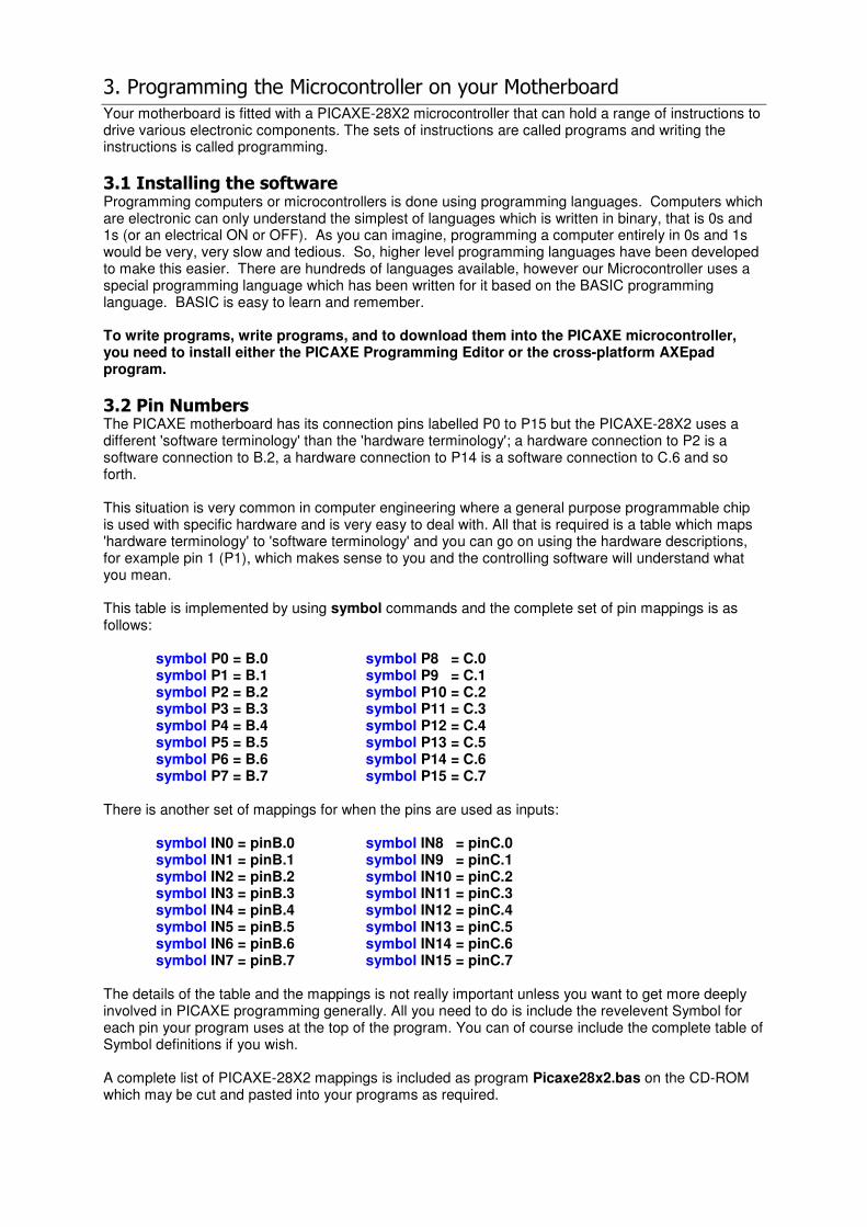
7. A good thing to do before writing code for a program is to draw a flow chart of how the program will work. Here is an example of a flow chart that shows what our program will do:
START
Turn on LED
Keep on for 200
milliseconds
Turn off LED
Keep off for 200
milliseconds
8. Write the following program into the text window. NOTE: It is important to type in exactly what is shown, because programming languages use very specific code called syntax. If the syntax is incorrect, the software, and later the hardware which is getting an interpreted version in binary, will not be able to read it. Note that the space indents and Tab key alignments are used to make your program easier to read. Writing after a single-quotes are comments and don’t affect the compiling or how the program operates.
symbol P0 = B.0 ' Define Output P0
do ' Do the following ... high P0 ' Set P0 high (5V)
pause 200 ' Keep P0 high for 200ms
low P0 ' Set P0 low (0V) pause 200 ' Keep P0 low for 200ms
loop ' Repeat this loop forever
Some things to note about the program above:
• Notice that we have used space characters to indent parts of the program and the Tab key to align things. This isn’t necessary, but makes it easier to read.

• Notice that the parts in grey after the single-quotes are descriptions of what the program is doing. These also aren’t necessary, but help you to understand what your program is doing, and to remember what it was doing when you come back to it in a year’s time (so spelling mistakes don’t matter in here).
• Note that we are using P0 which is an output so specified P0 in the High and Low commands, and provided the symbol definition required for P0 at the top of the program.
• We used a do / loop to keep the program ‘running round in circles’. The program will continually repeat the commands within that loop until the Versabot is turned off or a new program is downloaded to it.
9. Save your program to disk using the File/Save menu option and save your file as LEDprogram.bas.
10. It is very important to save your programs. Although the Versabot will remember what program was last downloaded to it, there is no way to read the program out of the Versabot later. If you want to have a copy of your program you must save it to disk.
11. Make sure the download cable is securely connected to your computer and to the download connector on your Versabot motherboard. Also, make sure your Versabot motherboard has batteries and is switched on
12. Press the F4 key ( or use the PICAXE/Check Syntax menu option ) to check the syntax of your program. If you have made any mistakes in typing your program the compiler will indicate what they are’ click OK and correct any mistakes. When you have the program correct the compiler will report “Syntax check successful!” and give an indication of how big your program is, how much space is required to store that program.
13. Press the F5 key ( or use the PICAXE/Program menu option ) to download your program into the PICAXE on your Versabot motherboard. A display screen will pop-up to show progress of the program being downloaded.
14. Once the downloading has completed, you should see the light at pin 0 start to flash. You can disconnect the serial cable and it will keep going. The program stays permanently in the PICAXE memory, so you can turn the flashing LED on and off using the motherboard power switch.

3.4 Adding a Slide Switch
1. Now let’s attach a slide switch and use it to control the speed of flashes on the LED.
2. Attach the Slide Switch module to P0 on the edge of your Micobric motherboard next to the LED module (note the 0 and 1 written in gold on the module).
3. Again, let’s draw a flow diagram before we write the program. Here is one for the program we will write.
START
Turn on LED
Keep on for 200
milliseconds
Turn off LED
Keep off for 200
milliseconds
Is switch on?
Turn on LED
Keep on for 2000
milliseconds
Turn off LED
Keep off for 2000
milliseconds
Yes
No

4. Now change the program so that it is the same as below. It is just the same as above but modified with an if / else / end if statement (to set up two possible paths for the program to follow):
symbol P0 = B.0 ' Define Output P0 symbol IN1 = pinB.1 ' Define Input P1
do ' Do the following ... if IN1 = 1 then ' When the slide switch is a 1 ...
high P0 ' Set P0 high (5V) pause 200 ' Keep P0 high for 200ms
low P0 ' Set P0 low (0V)
pause 200 ' Keep P0 low for 200ms else ' Otherwise ( slide switch is a 0 ) ...
high P0 ' Set P0 high (5V) pause 2000 ' Keep P0 high for 2000ms (2s)
low P0 ' Set P0 low (0V)
pause 2000 ' Keep P0 low for 2000ms (2s) end if
loop ' Repeat this loop forever
Some things to note about the program above:
• The module at Pin 1 accepts input from the user and so it is referred to as IN1. This tells the microcontroller to expect input at this pin. We also add the symbol definition for IN1 at the top of the program.
5. Save your program as SlideSwitchprogram.bas
6. Press the F5 key ( or use the PICAXE/Program menu option ) to download your program into the PICAXE on your Versabot motherboard. A Syntax Check is automatically performed before downloading so it isn’t necessary to press the F4 key ( or use the PICAXE/Syntax Check menu option ) before starting a download, but you can press F4 to check the syntax before downloading if you wish.
7. Once the downloading has completed you can switch the slide switch back and forth to see the difference in the LED flashing speeds.
8. The program downloaded completely replaces the previous program in the Versabot PICAXE and it will be remembered even while the Versabot is turned off. The Versabot PICAXE always remembers the last program downloaded to it, and only the last program downloaded.

3.5 Adding a buzzer
Now lets look at how the buzzer works. We will use the sound command to control the buzzer.
1. Connect the buzzer module to P2.
2. Now lets write a program that plays two different “tunes” depending on whether the slide switch is at 0 or 1. The flow diagram will look like this:
3. To program the buzzer, we will use the sound command. Let’s have a look at how the sound command works. The sound command takes the general form:
SOUND pin,( note1\duration1, note2\duration2 ……noteX\durationX )
pin: this is the pin number that the buzzer is connected to (i.e. P2) note: is a number between 1 and 127 that specifies the frequency of the note. duration: this is a value between 1 and 65535 telling the buzzer how long to stay on the given note for. You can put together a series of notes to make a tune by specifying note length and note frequency.
4. Start the Programming Editor or AXEpad, or start a new program by using the File/New/Basic Program menu option.
Start
Is the switch
1?
While the switch is on 1, play tune 1
If the switch is changed to 0
While the switch is 0, play tune 2
Yes
No

5. Now, type the following into the text window:
symbol IN1 = pinB.1 ' Define Input P1
symbol P2 = B.2 ' Define Output P2
do ‘ Do the following ...
do while IN1 = 1 ' While the slide switch is a 1 ...
sound P2, (100,50,110,50) ' Play two high tones
pause 500 ' And delay between tones loop ' Repeat this loop while the slide switch is 1
do while IN1 = 0 ' While the slide switch is a 0 ...
sound P2, (50,50,60,50) ' Play two low tones pause 500 ' And delay between tones
loop ' Repeat this loop while the slide switch is 0
loop ' Repeat forever
Some things to note about the program above:
• The do while command sets up a condition that while the switch is in a certain position (i.e the 1 position) a program sequence will follow. This will keep looping and will test the condition each time before it proceeds. As soon as that condition changes (i.e. The switch is moved to the 0 position) it will break out of the loop and continue through the code further down the program.
• Each do command has a corresponding loop command to show where the loop ends. Indentation is used so each do command lines up with its corresponding loop.
• Each sound command is just a two note tune in this case; more notes can be added as required.
6. Save your program as Buzzerprogram.bas.
7. Press the F5 key ( or use the PICAXE/Program menu option ) to download your program into the PICAXE on your Versabot motherboard.
8. Once the downloading has completed you can switch the slide switch back and forth to play the two different tunes.
9. Now we can modify the above program to include a LED and a buzzer and use the switch to interchange between the two.

START
Turn on LED
Keep on for 200
milliseconds
Turn off LED
Keep off for 200
milliseconds
Is switch on?
Play buzzer tune
Yes
No
symbol P0 = B.0 ' Define Output P0
symbol IN1 = pinB.1 ' Define Input P1 symbol P2 = B.2 ' Define Output P2
do ' Do the following ... if IN1 = 1 then ' When the slide switch is a 1 ...
high P0 ' Set P0 high (5V) pause 200 ' Keep P0 high for 200ms
low P0 ' Set P0 low (0V) pause 200 ' Keep P0 low for 200ms
else ' Otherwise ( slide switch is a 0 ) ...
sound P2, (100,50,110,50) ' Play two high tones pause 500 ' And delay between tones
end if loop ' Repeat this loop forever
10. Save your program as SlideSwitchprogram2.bas.
11. Press the F5 key to download your program into the PICAXE on your Versabot motherboard
12. When the slide switch is equal to 1, the LED will start to flash. If the slide switch equals 0, the buzzer will start playing the two-tone tune.

3.6 The Push Button
This section will give you an example of the use of a push button. Push buttons are extremely useful for a range of things and so the Button programming code has quite a number of parameters (parts to the code command that can vary).
1. Attach the Push Button module to P3 on the edge of the motherboard.
2. Start the Programming Editor or AXEpad, or start a new program by using the File/New/Basic Program menu option.
3. Now, type the following into the text window:
symbol P0 = B.0 ' Define Output P0
symbol IN3 = pinB.3 ' Define Input P3
symbol PushButton = IN3 ' Define the PushButton input
do ' Do the following ...
low P0 ' Initialise LED off if PushButton = 1 then ' When button pushed ..
gosub LightLED ' Call the LightLED subroutine
end if loop ' Repeat forever
LightLED:
high P0 ' Turn P0 LED on
pause 1000 ' Leave on for 1000ms (1s) return ' And return from subroutine
Some things to note about the program above:
• This time we have defined a variable called PushButton at the very beginning of the program. It is called a ‘variable’ because the value can vary according to input from the user. Note that the value for PushButton will be input at Pin 3 (IN3).
• We have added a subroutine to the program and given it the label LightLED. The name of the label should indicate what the function does. Subroutines are used to break up a long program into smaller ‘sub-programs’.
• Subroutines are called by using the gosub command and a subroutine returns control to the
line following the gosub command by using a return command. It is very important to add the return command at the end of each subroutine.
4. Save your program as PushButton.bas.
5. Press the F5 key to download your program into the PICAXE on your Versabot motherboard.
6. Press the button at Pin 3 to turn the LED on and off.
3.7 The Motor
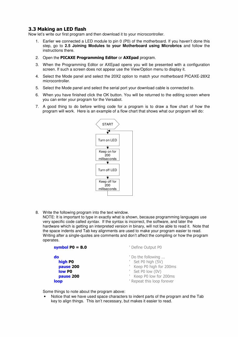
1. Attach the Motor module to P4 on the edge of the motherboard. Connect one of your wheels to the motor axle.
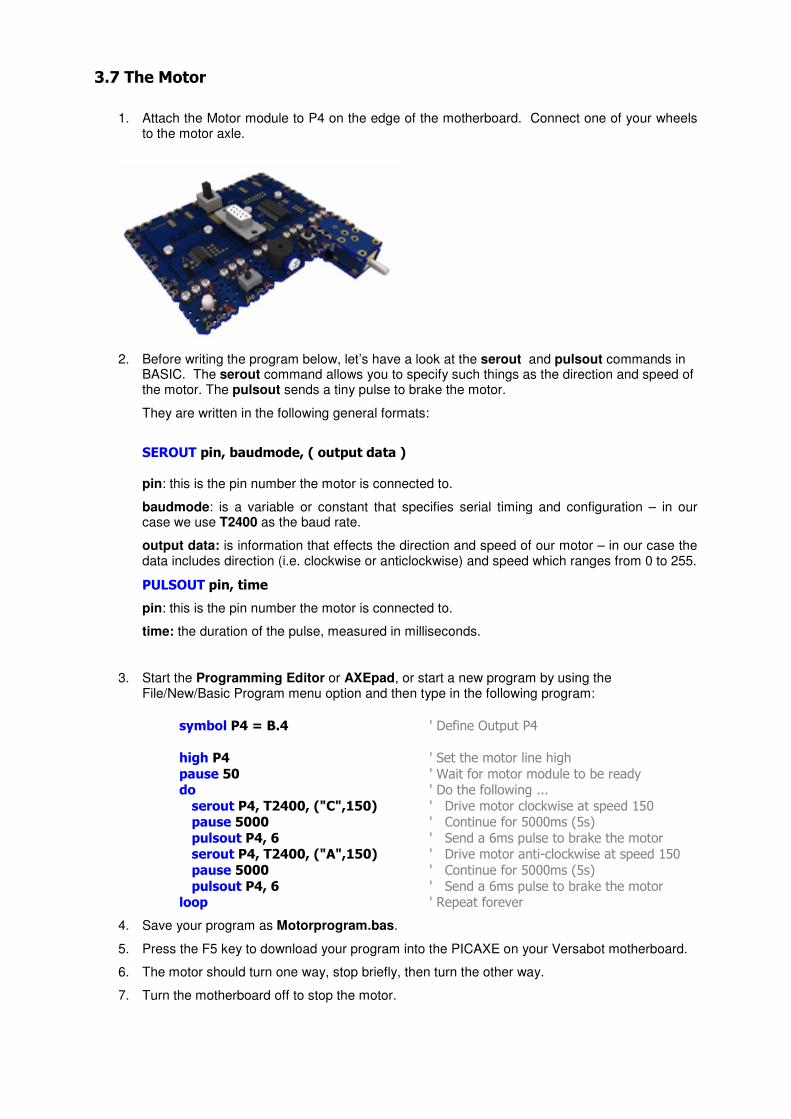
2. Before writing the program below, let’s have a look at the serout and pulsout commands in BASIC. The serout command allows you to specify such things as the direction and speed of the motor. The pulsout sends a tiny pulse to brake the motor.
They are written in the following general formats:
SEROUT pin, baudmode, ( output data ) pin: this is the pin number the motor is connected to.
baudmode: is a variable or constant that specifies serial timing and configuration – in our case we use T2400 as the baud rate.
output data: is information that effects the direction and speed of our motor – in our case the data includes direction (i.e. clockwise or anticlockwise) and speed which ranges from 0 to 255.
PULSOUT pin, time
pin: this is the pin number the motor is connected to.
time: the duration of the pulse, measured in milliseconds.
3. Start the Programming Editor or AXEpad, or start a new program by using the File/New/Basic Program menu option and then type in the following program:
symbol P4 = B.4 ' Define Output P4
high P4 ' Set the motor line high
pause 50 ' Wait for motor module to be ready do ' Do the following ...
serout P4, T2400, ("C",150) ' Drive motor clockwise at speed 150 pause 5000 ' Continue for 5000ms (5s)
pulsout P4, 6 ' Send a 6ms pulse to brake the motor serout P4, T2400, ("A",150) ' Drive motor anti-clockwise at speed 150
pause 5000 ' Continue for 5000ms (5s)
pulsout P4, 6 ' Send a 6ms pulse to brake the motor loop ' Repeat forever
4. Save your program as Motorprogram.bas.
5. Press the F5 key to download your program into the PICAXE on your Versabot motherboard.
6. The motor should turn one way, stop briefly, then turn the other way.
7. Turn the motherboard off to stop the motor.

3.8 The Bump Sensor Before using the Bump Sensor module, you will need to assemble the bump sensor itself.
1. Attach the Bump Sensor module to P5 on the edge of the motherboard.
2. Keep the assembled Versabot wheels off the ground or it may ‘run away’ with the download cable attached when you download your program to it.
3. Start the Programming Editor or AXEpad, or start a new program by using the File/New/Basic Program menu option.
4. Now, type the following into the text window:
symbol P0 = B.0 ' Define Output P0
symbol P4 = B.4 ' Define Output P4 symbol IN5 = pinB.5 ' Define Input P5
high P4 ' Set the motor line high
pause 50 ' Wait for motor module to be ready do ' Do the following ...
low P0 ' Initialise the LED off
do ' Go forwards ... serout P4, T2400, ("C",150) ' Drive motor clockwise at speed 150
pause 100 ' Continue for 100ms loop until IN5 = 1 ' Until the bump sensor is triggered
high P0 ' Turn LED on
pulsout P4, 6 ' Send a 6ms pulse to brake the motor serout P4, T2400, ("A",150) ' Drive motor anti-clockwise at speed 150
pause 2000 ' Continue for 2000ms (2s) pulsout P4, 6 ' Send a 6ms pulse to brake the motor
loop ' Repeat forever
5. Note the use of IN5 instead of P5 because we are getting input from a user.
6. Save your program as BumpSensorprogram.bas.
7. Press the F5 key to download your program into the PICAXE on your Versabot motherboard.

8. The motor should start turning the wheel clockwise. When the bumper is pushed, the LED should light and the wheel should change direction to anticlockwise.

3.9 The Infrared Receiver The Infrared Receiver module allows you to simply control your Versabot using a TV-like remote control. The TV remote control, if required, is available separately as part TVR010.
1. Attach the Infrared Receiver module to Pin 6 on the Versabot motherboard.
2. In order to use the remote control with the microcontroller, you will need to follow a sequence
of steps to preset the remote to work with the microcontroller. a. Put two AAA batteries into the remote control unit. b. Simultaneously hold down the S button (in the middle of the arrows) and the B button
on the remote (a red light will go on in the top left hand corner of the remote.) c. Press the number sequence 0 1 3 on the remote buttons. d. Press the red power button on the remote. e. The remote is now configured to work with your microcontroller.
Note that buttons A, C, D, E, F and G are for setting the remote control into different modes which are not required for this project. Avoid pressing these buttons as this will inadvertently set your remote into another mode. You can always return to the ‘B’ mode by pressing the B button.
3. Start the Programming Editor or AXEpad, or start a new program by using the
File/New/Basic Program menu option.
4. In this program you will be using the infrain command. This is a command that tells the microcontroller to wait for a remote control signal.
'**Variables** symbol keyPressed = w0
symbol timeout = w1
'**PICAXE motherboard pin definitions**
symbol P0 = B.0 symbol P2 = B.2
symbol P4 = B.4 symbol P6 = B.6
'**PICAXE motherboard input definitions**
symbol IN6 = pinB.6
'**IR Remote Keys**
symbol KEY_UP = 16 symbol KEY_DOWN = 17
symbol KEY_LEFT = 19
symbol KEY_RIGHT = 18
high P4 ' Initialise motor do
gosub ReadIrCommand ' Read the IR command gosub ObeyIrCommand ' Obey the IR command
loop

ReadIrCommand:
irin P6, keyPressed ' Read an IR comand
return
ObeyIrCommand: select case keyPressed
case KEY_UP : gosub GoForward ' When up arrow, clockwise
case KEY_DOWN : gosub GoBackwards ' When down arrow, anticlockwise case KEY_RIGHT : gosub LightLED ' When right arrow then light LED
case KEY_LEFT : gosub PlayTones ' When left arrow then play tones end select
return
GoForward:
serout P4,T2400,("C",255) ' Run motor forward gosub WaitWhileKeyHeld ' Wait for key release
pulsout P4,6 ' Stop Motor return
GoBackwards: serout P4,T2400,("A",255) ' Run motor backwards
gosub WaitWhileKeyHeld ' Wait for key release pulsout P4,6 ' Stop Motor
return
LightLED:
high P0 ' Turn LED on pause 1000 ' Keep on for 1000ms (1s)
low P0 ' Turn LED off return
PlayTones: sound P2,(50,50,60,50) ' Play two tones
return
WaitWhileKeyHeld: ' Wait until IR key released
timeout = 0 do
inc timeout if IN6 = 0 then
timeout = 0 end if
pause 1
loop until timeout > 25 return
5. Save your program as IRProgram.bas
6. Press the F5 key to download your program into the PICAXE on your Versabot motherboard.
7. Disconnect the download cable and place your Versabot on the ground.
8. Press the left, right, up and down buttons of your remote control to instruct your robot to do things; move forwards and backwards, play a tune and flash its LED
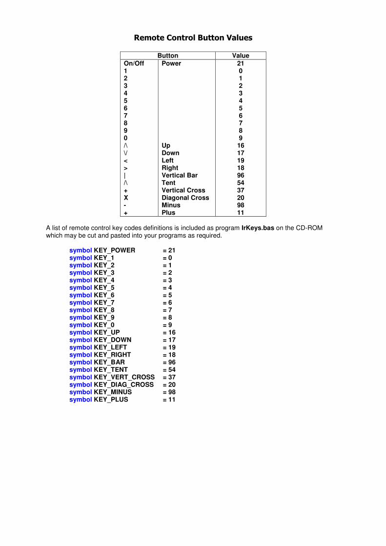
Remote Control Button Values
Button Value
On/Off 1 2 3 4 5 6 7 8 9 0 /\ \/ < > | /\ + X - +
Power Up Down Left Right Vertical Bar Tent Vertical Cross Diagonal Cross Minus Plus
21 0 1 2 3 4 5 6 7 8 9 16 17 19 18 96 54 37 20 98 11
A list of remote control key codes definitions is included as program IrKeys.bas on the CD-ROM which may be cut and pasted into your programs as required.
symbol KEY_POWER = 21 symbol KEY_1 = 0 symbol KEY_2 = 1 symbol KEY_3 = 2 symbol KEY_4 = 3 symbol KEY_5 = 4 symbol KEY_6 = 5 symbol KEY_7 = 6 symbol KEY_8 = 7 symbol KEY_9 = 8 symbol KEY_0 = 9 symbol KEY_UP = 16 symbol KEY_DOWN = 17 symbol KEY_LEFT = 19 symbol KEY_RIGHT = 18 symbol KEY_BAR = 96 symbol KEY_TENT = 54 symbol KEY_VERT_CROSS = 37 symbol KEY_DIAG_CROSS = 20 symbol KEY_MINUS = 98 symbol KEY_PLUS = 11
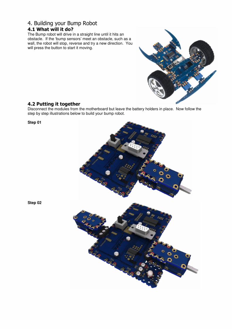
4. Building your Bump Robot 4.1 What will it do? The Bump robot will drive in a straight line until it hits an obstacle. If the ‘bump sensors’ meet an obstacle, such as a wall, the robot will stop, reverse and try a new direction. You will press the button to start it moving.
4.2 Putting it together Disconnect the modules from the motherboard but leave the battery holders in place. Now follow the step by step illustrations below to build your bump robot. Step 01
Step 02

Step 03
Step 04
Step 05

Step 06
Step 07
Step 08

Step 09
Step 10
Step 11

Step 12
Step 13

4.3 Downloading the program to drive your bump robot Once your bump robot is built:
1. Start the Programming Editor or AXEpad and open the file BumpRobot.bas from your CD-ROM ( File/Open).
2. Save the program (File/Save As…) to a location on you hard drive.
3. Connect the download cable to your motherboard. 4. Press the F5 key to download your program into the PICAXE on your Versabot
motherboard.
5. Disconnect the download cable and place your Versabot on the ground.
6. Press the button on the Button Module to start your Bump Robot.
4.4 The Code We have included the code here so that you can investigate the program used:
'**Variables** symbol temp = w0
'**PICAXE motherboard output pin definitions**
symbol P0 = B.0
symbol P1 = B.1 symbol P11 = C.3
symbol P12 = C.4
'**PICAXE motherboard input pin definitions**
symbol IN6 = pinB.6 Symbol IN13 = pinC.5
symbol IN15 = pinC.7
'**Outputs** symbol LeftLED = P0
symbol RightLED = P12
symbol RightMotor = P11 symbol LeftMotor = P1
'**Inputs**
symbol PushButton = IN6
symbol LeftBumper = IN15 symbol RightBumper = IN13
'Initialise Motor outputs
StartOfProgram: high RightMotor
high LeftMotor pause 50
StopRobot:
gosub StopMotors ' Call StopMotors low LeftLED ' Turn LeftLED off
low RightLED ' Turn RightLED off pause 250 ' Pause for 250ms
do ' Ensure no button pushed loop until PushButton = 0
do ' Wait until button pushed
loop until PushButton = 1

Main:
toggle LeftLED ' Swap the state of Left LED toggle RightLED ' Swap the state of Right LED
gosub GoForward ' Call "GoForward" pause 200 ' Pause for 200ms
if LeftBumper = 1 then BackwardTurnRight ' If right bumper sensor
' BackwardTurnRight if RightBumper = 1 then BackwardTurnLeft ' If the right bumper sensor
' BackwardTurnLeft if PushButton = 1 then StopRobot ' If Push Button is pressed
' StopRobot goto Main ' Loop around to Main
BackwardTurnRight: gosub StopMotors ' Call StopMotors
gosub GoBackwards ' Call GoBackwards gosub TurnRight ' Call TurnRight
goto Main ' Loop around to Main
BackwardTurnLeft:
gosub StopMotors ' Call StopMotors gosub GoBackwards ' Call GoBackwards
gosub TurnLeft ' Call TurnLeft goto Main ' Loop around to Main
GoForward: serout LeftMotor,T2400,("A",150) ' Drive motor Anticlockwise
serout RightMotor,T2400,("C",150) ' Drive motor Clockwise return
GoBackwards: pause 50
serout LeftMotor,T2400,("C",150) ' Drive motor Clockwise serout RightMotor,T2400,("A",150) ' Drive motor Anticlockwise
for temp = 1 to 25
pause 7 if PushButton = 1 then StopRobot ' If Push Button is pressed
' StopRobot next
gosub StopMotors pause 50
return
TurnRight:
serout LeftMotor,T2400,("A",150) ' Drive motor Anticlockwise serout RightMotor,T2400,("A",150) ' Drive motor Anticlockwise
for temp = 1 to 25
pause 15 if PushButton = 1 then StopRobot ' If Push Button is pressed
' StopRobot next
gosub StopMotors pause 50
return
TurnLeft:
serout LeftMotor,T2400,("C",150) ' Drive motor Clockwise serout RightMotor,T2400,("C",150) ' Drive motor Clockwise

for temp = 1 to 25
pause 15
if PushButton = 1 then StopRobot ' If Push Button is pressed ' StopRobot
next gosub StopMotors
pause 50
return
StopMotors: pulsout LeftMotor,6 ' Brake Left Motor
pulsout RightMotor,6 ' Brake Right Motor return

5. Building your Infrared Versabot Robot 5.1 What will it do? Your infrared Versabot can be driven using your remote control.
5.2 Putting it together Use the following diagram to see how the Versabot goes together. Having built the “Bump Robot” you should have no difficulties now building your Versabot.
5.3 Preparing the Remote Control In order for the Versabot microcontroller to receive signals from the remote control unit that has come with your kit, you will need to work through a preset routine.
1. Put two AAA batteries into the remote control. 2. Simultaneously press the S button (in the middle of the arrows) and the B button (at the top of
the remote) until the little red light goes on in the top left hand corner. 3. Now type in the numbers 0 1 3 4. Press the red power button 5. The remote is now ready to be used with your robot.
Note that buttons A, C, D, E, F and G are for setting the remote control into different modes which are not required for this project. Avoid pressing these buttons as this will inadvertently set your remote into another mode. You can always return to the ‘B’ mode by pressing the B button.
5.4 Downloading the program Once your Infrared Versabot robot is built:
1. Open Start the Programming Editor or AXEpad and open the file IRControlledRobot.bas from your CD-ROM ( File/Open).
2. Save the program (File/Save As…) to a location on you hard drive. 3. Connect the download cable to your motherboard. 4. Press the F5 key to download your program into the PICAXE on your Microbric
motherboard. 5. Disconnect the download cable and place your Versabot on the ground. 6. Press the direction arrows on your remote control to drive your Versabot.

5.5 The Code
'**Variables** symbol keyPressed = w0
symbol motorSpeed = w1 symbol timeout = w2
'**PICAXE motherboard pin definitions** symbol P6 = B.6
symbol P13 = C.5 symbol P14 = C.6
symbol P15 = C.7
'**PICAXE motherboard input definitions**
symbol IN14 = pinC.6
'**Pins** symbol LED_PIN = P6
symbol LeftMotor = P13
symbol RightMotor = P15 symbol IR_PIN = P14
'**Inputs**
symbol IR_SIGNAL = IN14
'**IR Remote Keys**
symbol KEY_UP = 16 symbol KEY_DOWN = 17
symbol KEY_LEFT = 19
symbol KEY_RIGHT = 18 symbol KEY_POWER = 21
symbol KEY_0 = 9 symbol KEY_1 = 0
symbol KEY_2 = 1 symbol KEY_3 = 2
symbol KEY_4 = 3
symbol KEY_5 = 4 symbol KEY_6 = 5
symbol KEY_7 = 6 symbol KEY_8 = 7
symbol KEY_9 = 8
'**Initialise Motor Outputs**
High LeftMotor High RightMotor
motorSpeed = 150 ' Initial motor speed pause 500
'**Main program Loop** do
low LED_Pin ' No IR command Gosub ReadIrCommand ' Read the IR command
High LED_Pin ' Set LED when obeying command
Gosub ObeyIrCommand ' Obey the IR command loop
ReadIrCommand:
IrIn IR_PIN, keyPressed ' Read an IR command
return

ObeyIrCommand:
select case keyPressed case KEY_UP : gosub GoForward
case KEY_DOWN : gosub GoBackwards case KEY_LEFT : gosub TurnLeft
case KEY_RIGHT : gosub TurnRight
case KEY_POWER : gosub StopMotors case KEY_0 : motorSpeed = 70
case KEY_1 : motorSpeed = 90 case KEY_2 : motorSpeed = 110
case KEY_3 : motorSpeed = 130 case KEY_4 : motorSpeed = 150
case KEY_5 : motorSpeed = 170
case KEY_6 : motorSpeed = 190 case KEY_7 : motorSpeed = 210
case KEY_8 : motorSpeed = 230 case KEY_9 : motorSpeed = 255
else : return
end select gosub WaitWhileKeyHeld
return
GoForward: serout LeftMotor,T2400,("A",motorSpeed)
serout RightMotor,T2400,("C",motorSpeed)
return
GoBackwards: serout LeftMotor,T2400,("C",motorSpeed)
serout RightMotor,T2400,("A",motorSpeed)
return
TurnLeft: serout LeftMotor,T2400,("C",motorSpeed)
serout RightMotor,T2400,("C",motorSpeed)
return
TurnRight: serout LeftMotor,T2400,("A",motorSpeed)
serout RightMotor,T2400,("A",motorSpeed) return
StopMotors: pulsout LeftMotor,6 ' Brake Left Motor
pulsout RightMotor,6 ' Brake Right Motor return
WaitWhileKeyHeld: ' Wait until IR key released timeout = 0
do inc timeout
if IR_SIGNAL = 0 then timeout = 0
end if
pause 1 loop until timeout > 25
return

6. What now? 6.1 More Programming Information There is so much more to the PICAXE 28X2 than what has been covered here. For further details on the PICAXE processors and programming language see the PICAXE Manuals accessible from the Help menu options of the PICAXE Programming Editor and AXEpad. 6.2 Cleaning up the edges You may find that the pieces that have been pushed out of the sheets have rough edges. Find a small file (a metal nail file will do) and gently file the edges smooth to perfect your robots.
6.3 Variations You now know enough about programming to make your own variations of the models provided. Experiment with a range of robot designs and write or adapt the programs to drive your new robots.
6.4 Go Online Want more? Go online to www.picaxe.com to find out the latest news in PICAXE Robotics! Join an online forum. Find out the newest models and designs. Buy additional pieces or replace missing ones. Check out the FAQs to troubleshoot problems, or Contact the PICAXE team.