the vol 21 no 5 december 1967 radio 2'6constructor a …
TRANSCRIPT
THE
RADIO CONSTRUCTOR
Vol 21 No 5
DECEMBER 1967
2'6
A DATA PUBLICATION
RADIO . TELEVISION ELECTRONICS AUDIO
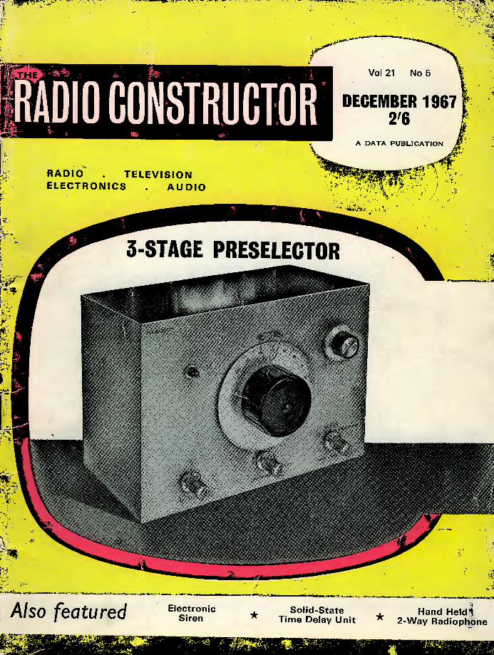
3-STAGE PRESELECTOR
■
i ■ 3
Also footu red Electronic Solid-State Handheld nioiy /CULUICU Siren * Time Delay Unit * 2-Way Radiophone
Scottish
66-67
Insurance Corporation Ltd
CORNHILL • LONDON • EC3
TELEVISION
SETS,
RECEIVERS
AND
TRANSMITTERS
Television Sets, Receivers and Short Wave Transmitters are expensive to acquire and you no doubt highly prize your installation. Apart from the value of your Set, you might be held responsible should injury be caused by a fault in the Set, or injury or damage by your Aerial collapsing.
A "Scottish" special policy for Television Sets, Receivers and Short Wave Transmitters provides the following cover:
{a) Loss or damage to installation (including in the case of Television Sets the Cathode Ray Tube) by Fire, Explosion, Lightning, Theft or Accidental External Means at any private dwelling-house.
(b) (i) Legal Liability for bodily injury to Third Parties or damage to their property arising out of the breakage or collapse of the Aerial Fittings or Mast, or through any defect in the Set. Indemnity £10,000 any one accident.
(ii) Damage to your property or that of your landlord arising out of the breakage or collapse of the Aerial Fittings or Mast, but not exceeding £500.
The cost of Cover {a) is 5/- a year for Sets worth £50 or less, and for Sets valued at more than £50 the cost is in proportion. Cover (6) (i) and (ii) costs only 2/6 a year if taken with Cover {a), or 5/- if taken alone.
Why not BE PRUDENT AND INSURE your installation—it is well worth while AT THE VERY LOW COST INVOLVED. If you write to the Corporation's Office a proposal will be submitted for completion.
Write for full details, quoting reference 5304, to:—
THE MANAGER
SCOTTISH INSURANCE CORPORATION LTD.,
66-67 CORNHILL, LONDON E.C.2

BI-PAK SEMICONDUCTORS London W.I
SCR's LOWEST PRICE YET LARGEST RANGE EVER (THYRISTORS) 1 AMP 7 AMP 16 AMP 30 AMP PIV (TO-5 can) (STUD) (STUD) (STUD) 25 — 7/6 — 30/- 50 7/6 8/6 10/6 35/- 100 8/6 10/- 15/- 45/- 200 12/6 15/- 20/- 55/- 300 15/- 20/- 25/- — 400 17/6 25/- 35/- 80/- 500 — 40/- 45/- 95/- 600 — 40/- 50/- — NEW SILICON RECTIFIERS TESTED
PIV 750mA 3 AMP 10 AMP 30 AMP 50 21- 31- 4/6 9/6 100 2/3 3/6 61- 15/- 200 2/6 4/6 6/6 20/- 300 31- 4/9 8/- 22/- 400 3/6 61- 91- 25/- 500 4/- 6/6 9/6 301- 600 4/3 71- 10/- 371- 800 4/9 8/- 15/- 40/- 1000 61- 10/- 17/6 501- 750mA TOP HAT TYPE 3. 10 and 30 A STUD TYPE TRANSISTOR MANUAL BY G.E. CIRCUITS, APPLICATIONS, INC. CHARACTERISTICS, L.A.S.C.R's. THEORY G.T. SWITCHES ^ Jv/" THEORY, RATINGS, 647 PAGES EACH APPLICATIONS. P.P. 2/6
S.C.R. MANUAL BY G.E. ± VALUE PACKS for '68
NEW . UNTESTED * 120 Glass Sub-Min. Germ. Diodes 10/- 50 Mixed Germ. Transistors 10/- 20 Mixed Volts Zeners 10/- 30 NPN. PNP, MIXED Sil. Trans. 10/- 60 200mA Sub-Min Sil. Diodes 10/- 20 Germ. 1 Amp. Rectifiers 10/- 40 Like OC8I, AC 128 T ransistors 10/- 10 2 Amp. Stud Sil. Rect. 10/- 25 Sil. NPN, 200 Mc/s Transistors 10/- 16 Top-Hat 750mA Sil. Rect. 10/- 75 GERM. DIODES Gold Bonded 10/- 20 Like BAY50 charge storage Diodes 10/- 10 50-400 PIV 1 Amp. SCR's 20/-
NEW TESTED NO DUDS
SUPER PAKS for 1968
rJ-
Our vast stocks change daily with hundreds of Semi- conductor bargains becoming available. Just send 2/6 to cover 3 months mailing of our latest stock lists, eqvt. charts, circuits, etc. Minimum Order 10/-. CASH WITH ORDER PLEASE. Add I/- postage and packing per Order. GUARANTEED by return postal service. Overseas add extra for Airmail.
>1 n SIL PLANAR I.U NPN TRANS. SIM.
v': 2N706/8 2N9I4 BSY26/7 2SI03/4
30 GERM. ALLOY
AF TRANS. PNP >/SIM 2G300 Series. OC7I/75 AC 125/8
50 SIL. PLANAR 250mA DIODES
SIM IS 121/130 OA200/202
12 EPOXY 500mA Sil. RECTIFIERS 100-600 PIV SIM BYI0I BY 130
30 MADT's PNP Metal Alloy Diffused. Trans. SIM MATIOI/2 MA393
30 FAST SWITCH PLANAR DIODES
SIM IN9I4/9I6 BAY 31/38
10 SIL. 1 AMP.
GLASS RECTIFIERS 200-800 PIV.
ALL AT PER PAK
UNCODED DEVICES 10/-
-A- QUALITY-TESTED VALUE PAKS — NOW MORE FOR YOUR MONEY 2 Drift Trans. 2NI225 Germ. PNP 100 Mc.s 10/- 6 Matched Trans. OC44/45/81/8ID 10/- 16 Red Spot AF Trans. PNP 10/- 16 White Spot RF Trans. PNP 10/- 5 Silicon Rects. 3 A 100-400 PIV 10/- 2 10 A Silicon Rects. 100 PIV 10/- 2 OCI40 Trans. NPN Switching 10/- 1 12 A SCR 100 PIV 10/- 3 Sil. Trans 25303 PNP 10/- 4 Zener Diodes 250mW 3-12V 10/- 3 200 Mc/s Sil. Trans. NPN BSY26/27 ... 10/- 3 Zener Diodes 400mW 33V 5% Tol 10/- 4 High Current Trans. OC42 Eqvt 10/- 2 Power Transistors I OC26 I OC35 10/- 5 Silicon Rects. 400 PIV 250mA 10/- 4 OC75 Transistors Mullard Type 10/- 1 Power Trans. OC20 100V 10/- 4 OA202 Sil. Diodes Sub-min 10/- 2 Low Noise Trans. NPN 2N929/30 10/- 1 Sil. Trans. NPN VCB 100 ZT86 10/- 8 OA8I Diodes (CV448) 10/- 4 OC72 Transistors Mullard Type 10/- 4 OC77 Transistors Mullard Type 10/- 5 Metal Alloy Transistors Mat Type 10/- 4 Sil. Rects. 400 PIV 500mA 10/- 5 GET884 Trans Eqvt. OC44 10/- 5 GET883 Trans. Eqvt. OC45 10/- 3 VHF Sil. Epoxy Trans. NPN 100 Mc/s ... 10/- 2 2N708 Sil. Trans 300 Mc/s NPN 10/- 5 GT4I/45 Germ. Trans. PNP Eqvt. OC7I... 10/- 3 GT3 I LF Low Noise Germ. Trans. PNP ... 10/- 6 IN9I4 Sil. Diodes 75 PIV 75mA 10/- 8 OA95 Germ. Diodes Sub-min IN69 10/- '3 NPN Germ. Trans. NKT773 Eqvt. AC 130 10/- 2 OC22 Power Trans. Germ 10/- 2 OC25 Power Trans. Germ. 10/- 2 OC73 Mullard Trans 10/- 4 AC 128 Trans. PNP High Gain 10/- 2 AC 127/128 Comp. pair PNP/NPN 10/- 10 Assorted Gold Bonded Diodes 10/- 3 2NI307 PNP Switching Trans 10/- 20 Germ. Diodes General Purpose 10/- 7 CG62H Germ. Diodes Eqvt. OA7I 10/- 3 AFI 16 Mullard Type Trans 10/-
FRFP One 10/- Pack of your own choice free rnCC with orders valued £4 or over FREE
12 Assorted Germ. Diodes Marked 10/- 4 AC 126 Germ. PNP Trans 10/- 5 I Amp Germ. Rect. 200 PIV 10/- 1 ORP6I Photo-conductive cell 10/- 4 Silicon Rects. 100 PIV 750mA 10/- 3 AFI 17 Trans. Mullard Type 10/- 7 OC81 Type Trans 10/- 3 OCI7I Trans. Mullard Type 10/- 3 2N2926 Sil. Epoxy Trans 10/- 7 OC71 Type Trans 10/- 2 GET9 Power Trans. 60 VcB. 8A 10/- 25 Trans. Heatsinks fit TOI8, SOI2, etc. ... 10/- 1 TK400A Power Germ. Trans = ADY22 ... 10/- 2 2S70I Sil. Trans. Texas NPN 10/- 2 Zeners Z2AI50F. 15V I watt 10/- 3 12 Volt Zeners 400mW 10/- 2 10 A 600 PIV Sil. Rects. IS425R 15/- 3 BCI08 Sil. NPN High Gain Trans 15/- 2 Zener Diodes 25W 18 and 22V 15/- 1 2N9I0 NPN Sil. Trans. VCI00 80Mc/s ... 15/- 2 1000 PIV Sil. Rect. I.5A RS3I0 AF 15/- 3 High Volt. AF Trans. PNP ACYI7 15/- 3 BSY95A Sil. Trans. NPN 200 Mc/s 15/- 3 OC200 Sil. Trans. Mullard 15/ 2 Sil. Power Rects. BYZ13 15/- I Sil. Power Trans. NPN 100 Mc/s TK201 A... 15/- 6 Zener Diodes 3-15 V Sub-min. 15/- I 2N I 132 PNP Epitaxial Planar Sil. Trans.... 15/- 3 2N697 Epitaxial Planar Trans. Sil 15/- 4 Germ Power Trans. Eqvt. OCI6 Mullard... 15/- 1 Unijunction Trans. 2N2646 Eqvt. D5E29... 15/- 2 Sil. Trans. 200 Mc/s 60Vcb ZT83/84 ... 15/- I Sil. Planar Trans. NPN 100 Mc/s BSY25 15/- 1 Sil. Trans. ISI04 ISO Mc/s HFE 200 NPN ... 15/- 2 SCRs 50 PIV I A TO-5 can 15/- I Tunnel Diode IN3720 (TD5) G.E 15/- 1 Unijunction Trans. 2N2I60 TO-5 can G.E. 15/- 2 Sil. Rects. 5 A 400 PIV Stud Type 15/— 2 Germ. Power Trans. OC28/29 15/- I 10 A Sil. Stud Rect. 800 PIV 15/- 1 Tunnel Diode AEYI I 1050 Mc/s STC ... 15/- 2 2N27I2 Sil. Epoxy Planar HFE225 max. ... 15/- 6 BY 100 Type Sil. Rects 20/- 25 Sil. & Germ. Trans. Mixed all Marked New 30/- 10 New Power Trans. GEC replaces OCI6/ 26/28 30/- I 2S024 Sil. Power Trans. NPN 100V I00W 30/- I Sil. Potted Bridge Rect. 800 PIV 2 A ... 30/- SEASON'S GREETINGS from BI-PAK SEMICONDUCTORS and a XMAS "GIFT DOLLAR" value 5/- redeemable with all orders of one pound or over. Not valid after 31st January, 1968. CUT ALONG DOTTED LINE
o o
JL
iimmm
m &
o o m SEMICONDUCTORS
4i MdAt
DECEMBER 1967 257
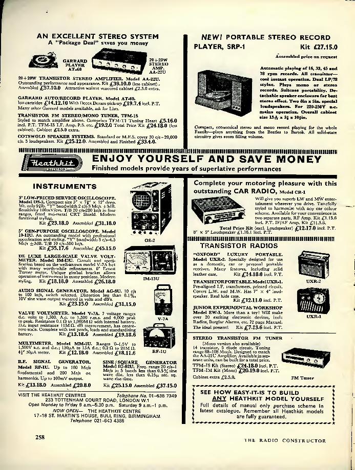
AN EXCELLENT STEREO SYSTEM A "Package Deal" sives you money
20 + 20W STEREO
AMP. AA-22U
GARRARD PLAYER
AT-60 20+20W TRANSISTOR STEREO AMPLIFIER. Model AA-22U. Outstanding performance and appearance. Kit £39.10.0 (less cabinet).. Assembled £57.10.0 Attractive walnut veneered cabinet ^2.5.0 extra.
GARRARD AUTO/RECORD PLAYER. Model AT-60. less cartridge £14.12.10 With Decca Deram pick-up £19.7.4 incl. P.T. Many other Garrard models available, ask for Lists. TRANSISTOR FM STEREO/MONO TUNER, TFM-1S Styled to match amplifier above. Comprises TFM-T1 Tuning Heart ^5.16.0 inch P.T. TFM-IS I.F. Amp. P.S. etc. £19.2.0 Total Price Kit £24.18.0 (less cabinet). Cabinet £2.5.0 extra. COTSWOLD SPEAKER SYSTEMS. Standard or M.F.S. cover 30 c/s-20,000 c/s. 3 loudspeakers. Kit £25.12.0. Assembled and Finished £33.4.0.
Illlllllllllllllllllllillillllllllllllllllil
NEW! PORTABLE STEREO RECORD PLAYER, SRP-1 Kit £27.15.0
Assembled price on request
Automatic playing of 16, 33, 45 and 78 rpm records. All transistor— cool instant operation. Dual LP/78 stylus. Plays mono or stereo records. Suitcase portability. De- tachable speaker enclosure for best stereo effect. Two Sin a Sin. special loudspeakers. For 220-250V a«c. mains operation. Overall cabinet size 15-ft- x 3{ z lO^in.
Compact, economical stereo and mono record playing for the whole Family—plays anything from the Beatles to Bartok. All solid-state circuitry gives room filling volume.
ENJOY YOURSELF AND SAVE MONEY Finished models provide years of superlative performances
INSTRUMENTS
3" LOW-PRICED SERVICE OSCILLOSCOPE. Model OS-2. Compact size 5" X 7f" x 12" deep. Wt. only 9|lb. "Y" bandwidth 2 c/s-3 Mc/s .-b3dB. Sensitivity lOOmV/cm. T/B 20 c/s-200 kc/s in four ranges, fitted mu-metal CRT Shield. Modern functional styling.
Kit £23.18.0 Assembled £31.18.0 5" GEN-PURPOSE OSCILLOSCOPE. Model 10-12U. An outstanding model with professional specification and styling. "Y" bandwidth 3 c/s-4.5 Mc/s ±3dB. T/B 10 c/s-500 kc/s.
Kit £35.17,6 Assembled £45.15.0 DE LUXE LARGE-SCALE VALVE VOLT- METER. Model IM-I3U. Circuit and speci- fication based on the well-known model V-7A but with many worth-while refinements. 6" Ernest Turner meter. Unique gimbal bracket allows operation of instrument in many positions. Modern styling. Kit £18.18.0 Assembled £26.18.0
AUDIO SIGNAL GENERATOR. Model AG-9U. 10 c/s to 100 kc/s, switch selected. Distortion less than 0.1%, 10V sine wave output metered in volts and dB's.
Kit £23.15.0 Assembled £31.15.0 VALVE VOLTMETER. Model V-7A. 7 voltage ranges d.c. volts to 1,500. A.c. to 1,500 r.m.s. and 4,000 peak to peak. Resistance 0.1 D to 1,000MQ with internal battery. D.c. input resistance 11MQ. dB measurement, has centre- zero scale. Complete with test prods, leads and standardising battery. Kit £13.18.6 Assembled £19.18.6 MULTIMETER. Model MM-1U. Ranges 0-1.5V to 1,500V a.c. and d.c.; I50p.A to 15A d.c.; 0.2 Q to 20M D. 4^ 50nA meter. Kit £12.18.0 Assembled £18.11.6
OS-2
nnvwrrn i
iS
IM-13U
V-7A nn
RF-1U
R.F. SIGNAL GENERATOR. Model RF-1U. Up to 100 Mc/s fundamental and 200 Mc/s on harmonics. Up to lOOmV output. Kit £13.18.0 Assembled £20.8.0
SINE / SQUARE GENERATOR Model IG-82U. Freq. range 20 c/s-1 Mc/s in 5 bands less than 0.5 % sine wave dist. less than O.lSp. sec. sq. wave rise time. Kit £25.15.0 Assembled £37.15.0
VISIT THE HEATHKIT CENTRES Telephone No. 01-636 7349 233 TOTTENHAM COURT ROAD, LONDON W.I
Open Monday to Friday 9 a.m.-5.30 p.m. Saturday 9 a.m.-l p.m. NOW OPEN— THE HEATHKIT CENTRE
17-18 ST. MARTIN'S HOUSE, BULL RING, BIRMINGHAM Telephone 021 -643 4386
Complete your motoring pleasure with this outstanding CAR RADIO, Modelcr-i
Will give you superb LW and MW enter- tainment wherever you drive. Tastefully styled to harmonise with any car colour scheme. Available for your convenience in two separate parts, RF Amp. Kit £1.13.6 incl. P.T. IF/AF Amp. Kit £11.3.6.
Total Price Kit (excl. Loudspeaker) £12.17.0 incl. P.T. 8" X 5" Loudspeaker £1.16.1 incl. P.T.
TRANSISTOR RADIOS "OXFORD" LUXURY PORTABLE. Model UXR-2. Specially designed for use as a domestic, car or personal portable receiver. Many features, including solid leather case. Kit £14.18.0 incl. P.T. TRANSISTORPORT ABLE. Model UXR-1. Pre-aligned I.F. transformers, printed circuit. Covers L.W. and M.W. Has 7" X 4" loud- speaker. Real hide case.
Kit £12.11.0 incl. P.T. JUNIOR EXPERIMENTAL WORKSHOP Model EW-1. More than a toy! Will make over 20 exciting electronic devices, incl: Radios, Burglar Alarms, etc. 72 page Manual. The ideal present! Kit £7.13.6 incl. P.T.
UXR-2
UXR-1
STEREO TRANSISTOR FM TUNER (Mono version also available)
14 transistor, 5 diode circuit. Tuning range 88-108 Mcc/s. Designed to match the AA-22U Amplifier. Available in sep- arate units, can be built for a total price. TFM-IS Kit (Stereo) £24.18.0 incl. P.T. TFM-IM Kit (Mono) £20.19.0 incl. P.T. Cabinet extra £2.5.0. FM Tuner
SEE HOW EASY-IT-IS TO BUILD ANY HEATHKIT MODEL YOURSELF
Full details of manual only purchase scheme in latest catalogue. Remember all Heathkit models
are fully guaranteed.
258 THE RADIO CONSTRUCTOR

NEW! STEREO AMPLIFIER, TSA-12 12x12 watts output. Kit £30.10.0 less cabinet Assembled £42.10.0 Cabinet £2.5.0 extra FOR THIS SPECIFICATION • 17 transistors, 6 diode circuit • ±_ IdB, 16 to 50,000 c/s at 12 watts per channel into 8 ohms • Output suitable for 8 or 15 ohm loudspeakers • 3 stereo inputs for Gram, Radio and Aux. • Modern low silhouette styling • Attractive aluminium, golden anodised front panel • Handsome assembled and finished walnut veneered cabinet available • Matches Heathkit models TFM-1 and AFM-2 transistor tuners. Full range power . . . over extremely wide frequency range. Special trans- formerless output circuitry. Adequately heat-sinked power transistors for cool operation—long life. 6 position source switch. FULL SPECIFICATION SHEET AVAILABLE
NEW! STEREO TAPE RECORDER, STR-1 Fully portable—own speakers
Kit £45.18.0 Assembled price on request FOR THIS SPECIFICATION • ^ track stereo or mono record and playback at 7^, 3J and 1| ips • Sound- on-sound and sound-with-sound capabili- ties • Stereo record, stereo playback, mono record and playback on either
channel • 18 transistor circuit for cool, instant and dependable operation • Moving coil record level indicator • Digital counter with thumbwheel zero reset • Stereo microphone and auxiliary inputs and controls, speaker/headphone and external amplifier outputs . . . front panel mounted for easy access • Push- button controls for operational modes • Built-in stereo power amplifier giving 4 watts rms per channel • Two high efficiency 8" x 5" speakers • Operates on 230V a.c. supply. Versatile recording facilities. So easy to build—so easy to use. FULL SPECIFICATION SHEET AVAILABLE
Build Britain's Best Electronic Kits No special Kit-building skills or Electronic Knowledge required lit
Low-priced STEREO FM RADIO
STEREO FM DECODER TUNER
SD-1 FM-4U
HI-FI FM TUNER. Mode! FM-4U. Available in two units. R.F. tuning unit (£2.15.0 inch P.T.) with I.F. output of 10.7 Mc/s, and I.F. amplifier unit, with power supply and valves (£13.13.0). May be used free standing or in a cabinet. Total Kit £16.8.0 (Multiplex adapter available, as extra.)
STEREO DECODER. Model SD-1. Converts FM Mono receivers to stereo at low-cost. Styled to match Heathkit models FM-4U and AFM-1 Tuners. Kit £8.10.0 Assembled £12.5.0
: inl
PI SSU-l
Heathkit"!
01
SPEAKER SYSTEMS HI-FI SPEAKER SYSTEM, Model SSU-l Ducted-port bass reflex cabinet in the white: Two speakers, vertical or horizontal models with legs. KIT £12.12.0, without legs, KIT £11.17.6 inch PT.
AVON MINI SPEAKER SYSTEM 6^" Bass, Sf" Treble speakers and crossover unit. Kit £4.18.0 inch PT. Beautiful. Walnut veneered fully-finished cabinet, £8.18.0, Total price Kit £13.16.0 inch PT.
Send for this Catalogue ...
... it's FREE! 36 pages packed with Britain's largest selection of electronic Kits. Mail coupon or write: DAYSTROM LTD., Dept. RC-12 GLOUCESTER. Tel. 20217.
"AMATEUR" EQUIPMENT THE "MOHICAN" GENERAL COVER- AGE RECEIVER. Model GC-1U. With 4 piezo-electric transfilters, variable tuned B.F.O. and Zener diode stabiliser, this is an excellent fully transistorised general purpose receiver for Amateur and Short wave listeners. Printed circuits, telescopic aerial, tuning meter and large slide-rule dial.
Kit £37.17.6 Assembled £45.17.6 AMATEUR BANDS RECEIVER. Model RA-1. To cover all the Amateur Bands from 160-10 metres. Many special features, including: half-lattice crystal filter; 8 valves; signal strength "S" meter; tuned R.F. Amp. stage.
Kit £39.6.6 Assembled £52.10.0 160-10M TRANSMITTER. Model DX- 100U. Careful design has achieved high performance and stability. Completely self- contained.
Kit £81.10.0 Assembled £106.15.0 COMMUNICATIONS TYPE RECEIVER. Model RG-1. A high performance, low cost receiver for the discriminating listener. Frequency coverage: 600 kc/s- 1.5 Mc/s and 1.7 Mc/s-32 Mc/s.
Kit £39.16.0 Assembled £53.0.0
Low-cost 3 + 3W Transistor Stereo Amplifier, TS-23 Incorporating all the essential features for good quality sound reproduction from record, radio and other sources. 16 Transistor, 4 diode circuit. Good frequency response 6 position selector switch. Modern slim line styling. Kit (less cabinet) £17.15.0
Kit (with handsome finished cabinet) £18.19.0
r r r r
To DAYSTROM LTD., GLOUCESTER Please send me FREE BRITISH CATALOGUE Please send me details of models □ □
NAME ADDRESS
j Please send a FREE Catalogue to my
I friend Name Address
I
RC-12 I RC-12
DECEMBER 1967 259

A no-compromise High Fidelity
loudspeaker, outstanding in its
performance and quality
^ Acoustically contoured sound chamber
^ Maximum loading in excess of 14 watts
0 Brilliant transient response
^15 ohms impedance
^ An all-British product
► SINCLAIR RADIONICS 22 NEWMARKET RD CAMBRIDGE
Telephone: OCA3 52996
SINCLAIR
0.14
Price need no longer stop you enjoying the best possible high-fidelity loudspeaker reproduction nor is size any longer a problem. (These con- siderations are of utmost importance to stereo enthusiasts.) In the Sinclair Q.14 you will find a loudspeaker of such superb quality and so com- pactly and attractively styled that you will want to change over to Sinclair immediately you hear it. At a recent trade demonstration experts were staggered by the quality of the Q.14. This is no ordinary loudspeaker. Much money, time and research have gone into producing a design which proves beyond question that good reproduction does not have to be expensive. Z.12 users know that full well, and coupling the Q.14 to this Sinclair amplifier assures superb audio reproduc- tion.
£6.19.6 pos
Independent laboratory testing shows exception- ally smooth response between 60 and 16,000 c/s with well sustained output both below and above these readings. Its remarkable transient response ensures clean-cut separation between instru- ments, voices, etc. The unusual shape of the sealed, seamless pressure chamber allows the Q.14 to be conveniently positioned on shelves, in wall corners, or flush mounted in assemblies of one or more units.
Try the Q.14 in your own home now. In stereo it is fantastically good. If you are not satisfied send it back and your money plus the cost of posting your Q.14 to us will be refunded in full.
FREE ANYWHERE IN THE UK
BHBS
260 THE RADIO CONSTRUCTOR

SINCLAIR Z.12 INTEGRATED 12 WATT
AMPLIFIER AND PRE-AMP
12 watts R.M.S. output con-
tinuous sine wave (24W PEAK)
15 watts music power (30W POWER)
Ideal for battery operation
15-50,000 c/s ± Idb
Ultra-linear class B output
The Sinclair Z.12 is the very embodiment of power, efficiency, reliability and economy. Nothing could be better than this fine amplifier for use with space-saving plinth-mounted motor and pick-up assemblies which are so popular today. Equally, light weight of the Z.12 makes it ideal for guitar amplifier or electronic organ. It operates efficiently on any power supply between 6 and 20V. D.C. The new Sinclair PZ.4 is particularly recommended as the power source. The pre-ampofthis8-transistor master- piece will accept the outputs of pick-up, radio and microphone, etc. and full details for matching control and selector switching circuits are in the manual supplied with each unit. The Z.12 is now in use all over the world and is the accepted standard for all hi-fi needs.
■
896 Built tested and guaranteed
SIZE 3" x If" x 1i"
SINCLAIR
i«
MICRO FM 7 Transistor
|k Superhet FM \ TUNER/RCVR
The only set of its kind in the world
TUNER RECEIVER Less than 3" x If x f this remarkable FM unit uses pulse counting discriminator for superb quality. Tunes 88-108 Mc/s. Teles- copic aerial suffices for good reception in all but poorest areas. Signal to noise ratio —30dB at 30 microvolts. One outlet for amplifier, the other allows set to be used as a pocket portable. Elegant aluminium front. Complete kit inc. aerial, earpiece / r 1 O A
and instructions. 1
Guarantee Should you not be completely satis- fied with your purchase when you receive it from us, your money will be refunded in full at once and with- out question.
PZ.4
NEW HEAVY DUTY STABILISED POWER SUPPLY UNIT
Designed specially for modern stereo needs, this new improved stabilised mains power unit delivers 1.5A at QQ /R 18V. D.C. For A.C. mains. Oil/ U
STEREO 25 De-luxe stereo pre-amp control unit with multi-stage matched input selector, treble, bass, volume and balance controls. Equalisation correct within ±1dB 50-20,000 Hz. Size 6f x 2f x 2i,, plus knobs. Front in brushed and polished aluminium.
£9.19.6
SINCLAIR
MICROMATIC
The world's
smallest radio
set NOW
• COSTS LESS Because sales and export orders for the Sinclair Micromatic are breaking all records, we have changed over to new production methods to meet the ever-increasing demand for the world's smallest radio set. This has enabled us to effect dramatic economies in production costs. At the same time, we have appreciably improved the set's quality by supplying a very high quality magnetic earpiece with it, and what was superb performance before, now sounds better than ever. At the new prices, everyone is going to want the Micromatic. Order yours now for Christmas.
IIICBDMAT
•wxiv'xr* • Plays
anywhere i Kit complete with magnetic earpiece, solder and instructions, originally 59/6, now
IM.W., A.G.C. and Bandpass
i Kit or Built
Ready built with mag- netic earpiece, orig- inally 79/6, now
49'6 59'6 Post Paid Post Paid
USE THIS ORDER FORM FOR DELIVERY BY RETURN If you prefer not to cut page, please quote R.C.I 2 when writing your order.
SINCLAIR RADIONICS LTD.. Please send me, post free
for which I enclose cash j cheque I money order value £ s d.
11 NEWMARKET RD., CAMBRIDGE NAME ADDRESS
DECEMBER 1967 261

NOW AVAILABLE . .
BOUND VOLUME No. 20
of "The Radio Constructor"
FOR YOUR LIBRARY
Comprising 780 pages plus index
Volume 20 August 1966 to July 1967
PRICE 32/6 Postage 4/6
Special discoant ol IO'-Ioi regular leaders
Where the 12 monthly issues making up the volume are returned, the price is only 22/6
plus 4/6 postage
BOUND VOLUME No. 19 August 1965 to July 1966 Limited number still available
same prices as above
Available only from:—
Data Publications Ltd.
57 Maida Vale London W9
An easy-to-build
S-STAGE
RECEIVER
m 5^ cw
You'll enjoy building 'The Clubman', an efficient 5-stager detailed in the Jan- uary PRACTICAL WIRELESS. Suitable for 160 and 80m. amateur and trawler bands. Parts readily avail- able at minimum cost. Facilities for adding extra stages, ranges and refinements.
-A/so in this issue-
INTERMITTENT FAULT LOCATOR, with own power supply, for those hard-to-trace faults. LEARNING MORSE from self-built practice oscillator. SIMPLE CRYSTAL TUNER—ideal gift for youngster.
WIRELESS
JANUARY ISSUE OUT 8th DECEMBER 2/6
262 THE RADIO CONSTRUCTOR

Bargains for
Winter Building
PEAK SOUND SA 8-8 STEREO AMP 14Transistor Kit builds into superb hi-fi amp. 8W per channel (I6W mono) with integrated pre-amp to take high quality ceramic p.u. Unusually easy to build. One of the best and most economical stereo transistor amps ever offered.
Amplifier Kit (P/P 4/-) £9.10 Power Pack Kit (P/P 4/-) £2.10 Modern Slimline Wood Cabi net (P/P 5/-) £2.10 Complete)Assembly £14.10.0 post free if ordered at same time. IRS MULLARD AMPLIFIERS
STEREO 10-10 Valve amplifier to exact Mullard spec. With pre-amp tapped o/p transformer 3 and ISO, all controls, H.T. and L.T. outlet, mono, stereo and speaker phase switching. Complete with escutcheon, knobs, plugs, etc., Ready ("p".1'!'P. 12/6) £20.0.0 Kit form due shortly tAH 1 ft O (p. & p. 12/6) H/.IU.U 3-3 MONO 3 valve 3 W amplifier with controls, absolutely complete kit including papd, Knobs, «c. £7.10.0 (P. & p. 7/6)
5-10 MONO 5 valve, I0W basic amplifier kit complete. /Q 40 A (p. & p. 7/6) tT.IT.O with passive control network and panel £11.19.6 2 valve pre-amp kit £6.12.6
GARRARD PLAYERS AND PLINTHS £8.15.0
£11.19.6
LM.3000 Record Player with 9 T.A. Stereo Cartridge. Brand new as from factory. AT.60 Mk.ll Deluxe Auto-changer. Die-cast T/Table, Less cartridge. SP.25 De-luxe single record player, less cartridge. Die cast. T/Table. Packing and carr. on any one of above, 7/6 extra. ' 2 Plinths. The ideal mounting for Units offered here. Will readily suit any hi-fi set-up. Teak finish with soft plastic TC/—. dust coyer. Packing and carriage 5/-. ' Jl Clear-view rigid plastic cover 57/6, (p. & p.3/6). Special Cartridge offer to purchasers of above items—5NBD Ceramic T/O Mono 17/6; TC/8M Crystal Mono 25/-; Decca Deram Stereo (List 94/6) 79/6; Ronette 105/S Stereo 32/6: Sonotone 9TA/HC 35/-.
VEROBOARD — All standard sizes including 2iin. x Sin. 3/8; 2iin. x 3Jin. 3/-; 3iin. x Sin. 5/2; 3jin. x 3Jin. 3/9; 2iin. x .17m. 12/6. All accessories and tools in stock. RESISTORS—Modern ratings, full range 10 ohms to 10 meg- ohms. 10% i-4W, 4d. each; 20% IW, 6d. each; 2W, 9d. each; 5% Hi-stab. iW, 5d. each; iW, 6d. each; 1.2-10 meg. 10% iW. 4d. each; ^W, 5d. each. 1% Hi-stab. ±W. 1/6 each (below I00D, 2/- each). CONDENSERS—Silver Mica. All values 2pF to 1,000 pF, 6d. each. Ditto ceramics 9d. Tub. 450V T.C.C., etc. 0.001-0.01 m F, lOd. each; 0.1-350V, lOd. each; 0.02- O.lmF, 500V, I/- each. T.C.C. 350V 0-25, 1/9 each; 0.5, 2/- each.
SAVE ON SPEAKERS TRS ACOUSTIC ENCLOSURE
Teak finished, 21" high x 15" wide by 7Jr" cut to take tweeter and 8" or 10" speaker to order. Acoustically pro- portioned for finest possible audio quality. Supplied ready to take units. SUPERB VALUE AT ONLY £4.15.6. Please add 7/6 as part of cost of packin g and carriage. 15 OHM SPEAKER UNITS
8" FR.8 Dual Concentric, 15 watts loading £5.15*0 8" Goodman's Twin Axiette, 15 watts loading £6.16.0
10" Goodman's Axiom £7. 5.0 8" Fane with 15000 line ceramic magnet and foam- surround cone suspension £4.10.0
SINCLAIR Q.I4 complete speaker 9J" square. Fantastic- ally good in stereo. Each £6.19.6 EMI 3 ohm elliptical 13^" x 8" 10 watts 55/-
7 VALVE AM/FM RG REPLACEMENT CHASSIS A superbly powerful high performance instrument for the keenest enthusiasts. Provides tuning on long, medium and F.M. wavebands. Excellent sensitivity. Permeability tuning on F.M. Large clear dial, A.V.C., good neg. feedback. Magic eye. 3W output. A.C. 200/250V. Circuit diagrams available. Aligned, tested and ready for use (Carr. and insurance 7/6). /II 10 A S.A.E. brings full details. 7,0
OUR NEW LISTS
feature more lines than ever at money saving prices. For latest issue please send 6d.
Please include S.A.E. with all enquiries.
TRS RADIO COMPONENT SPECIALISTS Established 1946
70 Brigstock Road, Thornton Heath, Surrey 01-684 2188. Hours 9 a.m.—6 p.m. I p.m. Wednesdays A few doors from Thornton Heath Stn. (S.R. Victoria sect/on).
SEMICONDUCTORS DISTRIBUTED
EXCLUSIVELY BY BI.PRE.PAK LTD., DEPT. E. 222-224 WEST ROAD. WESTCLIFF-ON-SEA, ESSEX PHONE: SOUTHEND (0702) 46344
NEW FROM THE U.S.A. "TEXAS" Integrated Circuits
SN7360 SN7430 SN7302 F.E.T'S. 2N3822
Quadruple 2 Input Nand/Nor Gate 8 Input positive Nand Gate Dual J-K Flip-Flop with pre-set Field Effect Transistors
*N* Channel 4-lead
19/6 21/6 35/-
15/- No. PRICE Al. 6—Silicon rectifiers BY 100 type 20/- A3. 20—Mixed marked and tested trans. 20/- A9. I—2N 174 real power trans. 80V I SOW 20/- AI5, 2—Power Comp. Pair. ADI6I/2 20/- Bl. 50—Unmarked untested, trans., new 10/- B2. 4—Solar cells, inc. Book of Instruc- tions 10/- B3. 4—OAS gold bonded, diodes Mul- lard 10/- B5. 7—Matched set, OC44, 45/8ID/8I + diode 10/- B6. 15—Red spot AF. trans, or white spot RF 10/- B8. 2—Power trans. OC26/35 type ... 10/- B9. I—Light sensitive cell, ORP12 type 9/- BI0. 10—50V trans, germ. PNP latest type 10/- B44. I—Tunnel diode, AEYI 1, 1050 Mc/s 10/- B2I. 2—Sil. recs. 10 amp., 50-100 P1V ... 10/- B42. 5—Switching trans. TK22C STC ... 10/- C2. I—Uni junction, 2N2I60 or 2N2646 15/- C4. 2—RF power trans., OC22 and BUYII 15/- C3I. 4—Sil. recs. 800 PIV | amp, top hat 15/- C32. 2—Power trans. TK400A/NKT404 VCB64 IC 8 amp 15/- DI8. I—ORP60 type light sensitive cell 5/-
BRAND NEW SAVE £'s WE TELL YOU
UNTESTED TEST THEM WHAT TYPES +
TRANSISTORS YOURSELF THEY ARE
DON'T TAKE
CHANCES ON
UNKNOWN
LOTS
25 NPN^siiicon TRANSISTORS 10/- 10<SSt"d
in 1000 PIV I amp. ,v Min. Silicon DIODES 10/- -jc BSY26-27 NPN Silicon TRANSISTORS 10/- ift 10 Watt Silicon IU All Voltages ZENERS 10/-
25 TRANSISTORS 10/-
RECTIFIERS 10/- 25 BC107-8-9 NPN Silicon TRANSISTORS 10/- 40 IN9I4-6 Sub. Min. Silicon DIODES 10/- Cft Min. Germ. High Quality DIODES 10/- ^ C 2N706 A NPN Silicon TRANSISTORS 10/-
TRANSISTORS PRICE AC 107 61- BSY27 AC 126 2/6 BSY28 AC 127 2/6 BSY29 AC 128 3/- BSY95A ACYI7 51- OC41 AFI 14 41- OC44 AFI 15 3/- OC45 AFI 16 3/- OC7I AFI 17 41- OC72 AFI 18 3/6 OC73 AFI 19 3/6 OC8I BCZI 1 7/6 OC8ID BFY50 15/- OC83 BSY25 10/- OCI39 BSY26 51- OCI40
5/- 51- 51- 51- 2/6 l/l' 1/9 2/6 2/6 51- 2/6 2/6 41- 2/6 51-
OCI70... OCI7I... OC200... OC20I... 2G30I ... 2G303 ... 2N697 ... 2N706 ... 2N71 I ... 2N I 302 2NI303 2NI304 2N i 305 2NI306 2NI307 2NI308 2N1309
2/6 2S303 2/6 41- POWER TRANSISTORS 51- OC20 10/- 81- OC23 10/- 2/6 OC25 Si- ll 6 OC26 51- 51- OC28 7/6 5/- OC35 51- 10/- OC36 7/6 41- DIODES 41- AAY42 II- 51- OA9 21- 51- OA 10 21- 61- OA70 1/9 61- OA79 1/9 81- OA8I 1/9 81- OA 182 21- free ★ * Packs of your own choice to the value of 10/- with all orders over £4.
SEND FOR OUR FREE LISTS AND CAT- ALOGUE OF ALL OUR PRODUCTS. CHECK YOUR OWN EQUIVALENTS WITH OUR FREE SUBSTITUTION CHART.
NO CONNECTION WITH ANY OTHER FIRM MINIMUM ORDER 10/- CASH WITH ORDER PLEASE. Add I/— post and packing per order. OVERSEAS ADD EXTRA FOR AIRMAIL.
Great News We now give a written guarantee with all our semi- conductors.
DECEMBER 1967 263

HOME RADIO (Mitcham) LTD., Dept. RC, 187 London Rd., Mitcham, CR4 2YQ Phone: 01-648 3282
$rii-L wy THATS eNou&H me MOWZCH OF WE GLEN"
I Ua t M navigating/
^ ^3
/ ' se Qr
5^5 opS>\o & o(^fc
t(*v
a mm
Well here's a pretty how de do! The Old Chap is
lost, to-night of all nights, and that stubborn old
Rudolph airing his navigational knowledge. Let's
hope he finds his bearings before the morning!
If you find yourself lost in the maze of components required for
your next project the surest way to find the way out is to get a
copy ofthatinvaluableguide, the Home Radio Catalogue. Surprise, surprise, although the Catalogue has been enlarged and improved
every year, the price remains at 7/6 p/us 2/- postage and packing.
So if you want some interesting Christmas reading send the coupon and p.o. or cheque without delay. Oh! and by the way, every catalogue contains 5 vouchers, each worth 1/- if used as
directed.
The Directors and
Staff of Home Radio
wish you all a
MERRY CHRISTMAS
and a
HAPPY NEW YEAR
Name BLOCK •CAPS
Address.
Home Radio (Mitcham) Ltd., Dept. RC, 187 London Road, Mitcham, CR4 2YQ
264 THE RADIO CONSTRUCTOR

THERadio Constructor "Hi
Incorporating THE RADIO AMATEUR DECEMBER 1 967
Vol. 21 No. 5
Published Monthly (1st of Month) First Published 1947
Editorial and Advertising Offices 57 MAIDA VALE LONDON w9
Telephone CUNningham 6141
Telegrams Databux, London
® Data Publications Ltd., 1967. Contents may only be reproduced after obtaining prior permission from the Editor. Short abstracts or references are allowable provided acknowledgement of source is given.
Annual Subscription 36s. (U.S.A. and Canada $5) including postage. Remittances should be made payable to Data Publications Ltd". Overseas readers please pay by cheque or International Money Order.
Queries. We regret that we are unable to answer queries other than those arising from articles appearing in this .magazine nor can we advise on modifications to equipment described. Queries should be submitted in writing and accompanied by a stamped addressed envelope for reply.
Correspondence should be addressed to the Editor, Advertising Manager, Subscription Manager or the Publishers as appropriate.
Opinions expressed by contributors are not necessarily those of the Editor or proprietors.
Production.—Letterpress/contact litho.
Published in Great Britain by the Proprietors and Publishers Data Publications Ltd. 57 Maida Vale London W9
Produced by Quicks the Printers, Clacton-on-Sea, England
Electronic Siren by W. Kemp
S.C./O.C. Tester Using an I.C. (Suggested Circuit No. 205)
by G. A. French
Trade News
Solid-State Time Delay Unit by B. T. Hathaway
Can Anyone Help?
News and Comment
Hand Held 2-Way Radiophone by F. G. Rayer, G30GR
"Rubber Zener" Circuits
3-Stage Preselector
by G. Short
by James S. Kent
Understanding Radio (Schmitt Phase Inverter)
by W. G. Morley
266
271
274
275
279
280
282
285
288
Sequential Flasher for Christmas Lights 296 by R. J. Caborn
Trade Review—Trio Communications Receiver Model 9R-59DE 298
Switch-on Delay for TV 300 by D. B. Hulse, A.M.Inst.E.
302
In Your Workshop 305 (Stabilised Power Supply, 0.5 to 16V output)
Semiconductor Materials, 311 by J. B. Dance, M.Sc.
DECEMBER 1967 265

-
ELECTRONIC
This article describes an ingenious warning device which immediately catches the attention of the continually varying output frequency that it generates. Particularly noteworthy features of the circuit are the use of a complementary 2-transistor multivibrator and the fact that all components remain connected across the battery when the oscillator is not actuated. To obtain the exceptionally low standby current given with the prototype, it may be necessary to select
transistors and electrolytic capacitors for low leakage current
This useful little circuit, which costs about fifty shillings to build, incorporates a number of unique design features and gives a performance
that is unlike that of any commercially available electronic siren. The circuit is permanently connected to a 9 volt battery supply, but generates no sound until a Start switch is operated. The circuit consumes a total current of less than IfxA when in the standby condition, so that the life of the battery is virtually equal to its shelf life under this condition.
When the Start switch is closed the siren generates a rich "gliding" tone which starts at a low frequency and builds up to a frequency of a few kilocycles per second over a period of 15 to 20 seconds, after which time the tone frequency stabilises. When the Start switch is opened the tone falls slowly in frequency, dying away completely after 20 to 30 seconds. Thus, the sound of the electronic siren is very similar to that of the air-raid sirens used during the last war.
tr, CP.N.P)
>R2 C|
-IK
/j/A ^2 \iV(N.PN.)
T"
Fig. 1. The basic astable complementary multivibrator circuit which is used in the siren
The circuit incorporates a pre-set volume control, and the maximum output power is equal to about 250mW r.m.s. Although this output level is not sufficient to attract the attention of the police, etc., it is sufficient to frighten away an intruder, and the device can thus be used as a burglar alarm. The unit is, however, primarily intended for normal domestic use to replace a bell or buzzer, and it has a distinct advantage over these alternative types of warning device since its varying tone is far more effective in attracting attention.
The electronic siren is ideally suited to operation by devices such as fire or smoke detectors, rain operated switches and proximity detectors.
Circuit Operation The circuit is developed from the basic astable
complementary multivibrator shown in Fig. 1, in which either both transistors are on or both transistors are off. The circuit operates in the following manner.
Base current to TR) is derived from the negative supply line via Rj, and base current to TR2 is derived from the positive supply line via R3 and TR]. Thus, if Si is open-circuit no base current will flow to TRi and this transistor will be cut off and, since TRi 4s cut off, no base current can flow in TR2 and that transistor will be cut off also. If Si is now closed TRi will begin to conduct, thereby supplying base current to TR2 and driving that transistor hard on; as TR2 is driven hard on a large part of the supply voltage will be dropped across R2, causing TR2 collector to move towards zero volts with respect to the negative supply line. This excursion will be communicated to TRi base via Q, thereby driving TRi hard on, until both transistors become saturated. Q then charges up rapidly via the two transistors until a point is reached at, which the base current of TRi starts
266 THE RADIO CONSTRUCTOR
SIREN
by W. Kemp
to decrease. This decrease in current is then trans- mitted, in amplified form by way of TR2, R2 and Cj, back to TRi base, so that a regenerative action takes place and both transistors cut off. Cj then discharges, with a fairly long time constant, via Ri, until TRj just begins to conduct again, and the cycle then repeats itself ad infinitum. A rectangular waveform, with a wide mark-space ratio, is generated by the circuit.
The frequency of operation of the circuit can be altered by varying the basic base current of TRi, this being achieved by either varying the value of Ri or the voltage that is fed to the low end of Ri. In either case the frequency of operation will rise as the base current is increased, i.e. as Ri is reduced, or as the low end of Ri is made more negative.
The circuit can be switched off either by dis- connecting the battery supply, or by opening Si. In the latter case both transistors will switch off, and the only current consumed will be the leakage currents of TRi and TR2 which, assuming that silicon transistors are used, will normally be less than 1ij.A.
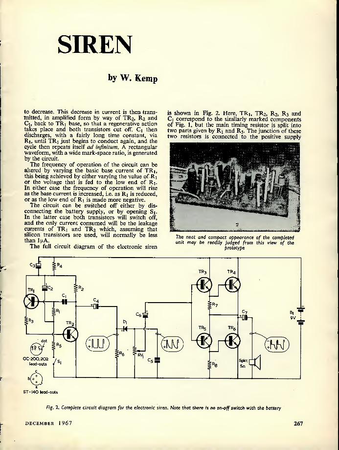
The full circuit diagram of the electronic siren
is shown in Fig. 2. Here, TRi, TR2, R2, R3 and Ci correspond to the similarly marked components of Fig. 1, but the main timing resistor is split into two parts given by Ri and R5. The junction of these two resistors is connected to the positive supply
The neat and compact appearance of the completed unit may be readily judged from this view of the
prototype
i C3 T
C2 TR
I 6
I TR
;im dot
:MVf / gR5 SK Rv
0C-200,202 ",s lead-outs / 1
b o
bT-140 lead-outs
TR3 TR4
C7 ^01-
TR TR
Spkr 5n
Fig. 1. Complete circuit diagram for the electronic siren. Note that there is no on-off switch with the battery
DECEMBER 1967 267

line via C2 and C3, R4. Thus, at the moment that Si is closed, C2 will be discharged and the potential at the junction of Ri and R5 will be close to that of the positive supply line, with the result that the circuit will oscillate at a fairly low frequency. C2 will then charge up via R5 so that the potential at the junction of Ri and R5 will move negative in an exponential fashion, causing the operating frequency to rise in a similar manner, until finally C2 will be fully charged and the operating frequency becomes stabilised. When Sj is reopened, C2 will discharge itself via Rj and the emitter-base junction of TRi, causing the frequency of operation to decay in an exponential manner until C2 is fully discharged, whereupon the circuit ceases to operate.
C3 and R4 supply a degree of d.c. negative feed- back to the oscillator, enabling the circuit to operate correctly over a wide range of transistor gain spreads. The final stabilised oscillation frequency is con- trolled by Ci, while the period of the rising siren effect is controlled by C2 and R5, and that of the falling siren effect by C2 and Rj.
The waveform generated by the oscillator is of rectangular form, as shown, but has a wide mark- space ratio so that although the peak amplitude of the signal is quite large the mean value is fairly small. This snag is to some degree overcome by feeding the signal from TR2 collector to Re via C4, and then on to the shaping circuit given by Dj, RVj and C5. This circuit modifies the waveform as shown and increases its mean value. A portion of this modified waveform is taken from the slider of RVj, which acts as a volume control, and fed to the power amplifier stage via Cg.
The power amplifier stage comprises TR3, TR4, TR5, TRg, TR7 and Rg, these being wired in the well-known complementary emitter follower mode. The amplifier stage gives near-unity voltage gain with a very low output impedance, whereupon this output is used to drive the 5fl speaker via C7. The present circuit is unusual, however, in that no base-biasing is applied to the transistors, so that, in the absence of an input signal, all transistors are cut off and consume negligible current from the supply. The absence of base-biasing on the transistors results in considerable crossover distortion, which proves to be an advantage in this particular ap-
s
L I
plication since it modifies the output waveform as illustrated and thereby increases the mean power of the signal. Also, the crossover distortion in- creases the harmonics in the output and thereby harshens the quality of the siren.
From the output waveform shown in Fig. 2 it can be seen that a very large pulse or spike of current is fed into the speaker, and it is the magnitude of this spike that limits the available mean output power to 250mW. It is important to note that the speaker used must have an impedance of SO or greater, and that a 9 volt supply must be used. Do not use a speaker impedance less than SO, nor a supply voltage in excess of 9 volts*
The standby current of the circuit (with Si open) is of the order of 1 [xA, the actual current measured on the prototype being O.bfiA at normal room temperature.
Construction Before starting construction of the unit, a check
should be carried out on all transistors to ensure that they have leakage currents, with base open- circuit, of less than lixA when connected across a 6 volt supply. In practice, it will usually be found that leakage currents are so small that no reading can be obtained on a standard meter. It should be noted that the completed circuit will still work perfectly well even if all transistors have leakage currents of several (xA, but that the standby current of the unit will then be correspondingly higher.
The unit is wired up on a small piece of Vero- board, which measures If x 3|in and has 0.15in hole spacing, and construction should be started by cutting this panel to size and drilling the two small mounting holes, to clear 6BA screws, as shown in Fig. 3. The copper strips should then be broken, with the aid of a small drill or the special cutting tool that is available, in the positions indicated.
The components and leads, etc., should be soldered in place on the blank side of the panel in the positions indicated in the lower part of Fig. 3 and here it should be noted that all components other than Rg are mounted vertically and that insulated sleeving should be used where there is any danger of com- ponents short-circuiting against one another. Also, the mounting legs of RVj should be reduced in width with the aid of a small file, so that they fit in the holes in the panel, before attempting to solder this component in place.
It is recommended that the wiring up be carried out in a number of stages, so that each section of the circuit can be checked and tested for faults before proceeding with the next stage. The following procedure may then be carried out.
Wire TRi, TR2, Ri, R2, R3, R4, Rs, Q, C3, C4, Si (complete with leads), and the positive and negative battery supply leads in place on the panel. Do not solder C2 in place at this stage. Now
♦If desired, transistors TR4 and TRg could be fitted with small cooling fins to increase dissipation. Since the metal cases of the transistors specified are common to their collectors, these fins must not touch each other or any other connections or wiring in the circuit. —Editor.
268 THE RADIO CONSTRUCTOR

Resistors (All fixed values \ watt 10%)
■ components!
Ri 120k£l Semiconductors R2 2700 TRj OC200 or OC202 (Mullard) Rj 180Q TRj ST140 (Sinclair) R4 IkO TR3 ST140 (Sinclair) Rs 82kO TR4 ST140 (Sinclair) Re IkO TR5 OC200 or OC202 (Mullard) R7 8200 TRe ST 140 (Sinclair) Rg 8200 Dj OA200 or OA202 (Mullard)
Switch RVj 5kO, skeleton pre-set potentiometer
Capacitors Si s.p.s.t. switch (see text) (All electrolytic capacitors should be good- quality low-leakage types) Battery
Q 0.01 (xF Bi 9-volt battery C2 100(xF electrolytic, 12V wkg. C3 l[xF electrolytic, 12V wkg. Miscellaneous C4 I6:j-F electrolytic, 12V wkg. Loudspeaker, SO impedance or greater C5 0.1 [xF Veroboard, 0.1 Sin matrix, dimensions as in Ce l6u.F electrolytic, 12V wkg. Fig. 3 C7 100 to 250ixF electrolytic, 12V wkg. Connecting wire, sleeving, etc.
A - drill 6BA clear
33/8*-
o o • • ( o 1 o OOP
□ on • O O t O ) o o o o o o o o
• ♦ o
• o o I!°D
• ( o) o o o o o 3 O ) • o o o • o
IP 13=
□pt
EH
13/8*
2 3 4 5 6 7 8 9 IO II 12 13 14 15 16 17 18 19 20 31 22
• battery + (9V)
o o O O O O 0 0 o
? i: A: TkQ-:1
0= <3 1*0 5n speaker
JRs ° O
■ h o o • H
tr2 RV • o
2
7 battery —
Fig. 3. The upper section of this diagram illustrates the manner in which the copper strips are cut, whilst the lower section shows the components mounted
in position on the Veroboard
DECEMBER 1967 269

temporarily connect a crystal earpiece between the negative supply line and the negative side of C4 and, with Si open, connect the 9 volt battery in place and check that the circuit draws a current of less than 2;jA. Next, close Si and check that a powerful and steady tone is heard in the earpiece, and that the circuit draws a current of approximately 1 to 2mA. If the circuit does not pass these tests, a fault is indicated and this should be cleared up before proceeding with the next stage of con- struction.
When the above checks have been completed satisfactorily. Si should be opened and C2 should be soldered in place. When Si is closed again, the tone should, after a fraction of a second, start to operate at a fairly low frequency and then begin to rise until, after a period of approximately 15 to 20 seconds, it stabilises at a fairly high frequency. When Si is opened again the tone should decay in frequency, dying away after about 20 to 30 seconds. The supply current should then decay slowly to less than 2gA.
Remove the crystal earpiece from the circuit and solder Re, Di, RV}, C5, and C6 in place, and then, reconnect the earpiece between the negative supply line and the positive side of Ce- Check that the siren operates in the manner already described by closing and opening Si, and that the volume of the signal can be varied by means of RVi. If results are satis- factory, remove the earpiece from the circuit.
Now wire TR3, TR4, TRj, TRg, R7, Rg, C7 and the link in place and, with Si open, check that the total current consumed by the unit is less than 4pA. It should be noted that, initially, the capacitors in the circuit may be only partially formed so that a fairly high current reading is obtained, but that the current should slowly decay to the above figure within a few minutes. In practice, an eventual total reading of less than l[xA can be expected if good quality capacitors are used.
If this test is satisfactory, connect the 5fl speaker in place and check that there is no significant increase in current, apart from a momentary surge
as the connection is made. If there is a significant and sustained increase in current, a high-leakage capacitor in the C7 position is indicated, and this component should be replaced.
Finally, a check should be made that the siren operates in the manner already described by closing and opening Si, and ensuring that a reasonably high volume (about 250mW) of output is available. Also confirm that the volume can be varied by means of RVi, which can be pre-set to give the required level of output volume. The circuit is then complete and ready for use.
Using The Unit The unit can, if required, be mounted in a case
or to a small chassis by passing 6BA screws through the two small mounting holes that are pro- vided and securing these to the chassis. Fit two small rubber grommets to act as spacer-insulators between the copper side of the Veroboard and the surface to which it is secured. If the Veroboard is mounted in this fashion, clear the copper away from the 6BA holes (at points adjacent to 20f and 3b in Fig. 3) so that there is no risk of short- circuits to the mounting screws.
In practice, Si may be replaced by a microswitch or the contacts of a relay, so that the unit can be operated (using the microswitch) by the opening of doors or windows, etc. or (using the relay) by electronic devices such as rain detectors, smoke or flame detectors, proximity switches, etc. Several microswitches or sets of relay contacts can, if preferred, be wired in parallel across the Si position, thereby enabling the siren to be activated by any one of a number of "detector" devices.
The unit should be permanently connected to its 9V battery. The standby current is so small that, when using a small PP3 battery, a theoretical battery "life" of approximately 10 years is available! In practice, of course, the shelf life of a normal battery is considerably less than this, so that the "ideal" 10 years of life cannot be obtained. ea
| We wish all our readers |
I a uery Happy Christmas |
s and a Prosperous New Year—Editor »
li ^ »»»»»»»»»»»»»»»»»»»»»»
77n THE RADIO CONSTRUCTOR

P7 vov^
C6 52 C2
Cb C-J
S.C./O.C. Tester Using
an I.C.
SUGGESTED CIRCUIT No. 205
NOW THAT INTEGRATED CIRCUITS (I.C.'s) are becoming available through home-constructor
retail channels at prices comparable with the discrete transistors, diodes and resistors which they replace, it becomes an interesting challenge to find simple applications for them which take utmost advantage of their unique characteristics.
The low cost I.C.'s available at the time of writing are primarily intended for digital computer and control functions, and the writer felt it would be worthwhile devoting this month's article to a device which employed an I.C. in a circuit application fairly similar to that for which it was originally designed. The main intention was to use as much of the internal circuitry of the I.C. as was possible, reducing external components to a minimum. The resultant device would then be roughly comparable in cost with a similar circuit using separate silicon transistors, as well as being smaller and involving much less work in wiring and connecting up. Perhaps most important of all, however, the device would enable practical experience to be obtained with a fascinating new development which may well, in the future, completely alter the world of electronics as we see it today.
The Integrated Circuit The integrated circuit chosen by
the writer was the Fairchild (iL914 Dual Gate, this incorporating 4 n.p.n. transistors and 6 resistors in two separate gate functions. This I.C. is available from advertisers in this journal. The u.L9i4 has an epoxy resin encapsulation which
provides a circular housing with a diameter of about 0.3in and a height of about 0.1 Sin. Connections are made by way of 8 lead-outs projecting from the lower surface of the housing.
The internal circuitry of the U.L914 is shown in Fig. 1 (in which the designations TRi to TR4 have been added for convenience of explanation here). In normal use, terminal 8 connects to a positive source of supply and terminal 4 to a negative source of supply. The appropriate transistor inside the I.C. then becomes conductive when any of the terminals 1, 2, 3 or 5 are made positive. As may be seen, TRi and TR2 can function, for instance, as a NAND gate. The
by G. A. FRENCH
output, at terminal 7, will only go positive when both terminals 1 and 2 are negative. Other gate functions offered by two transistors with their collectors connected to a common output are also readily obtained. Transistors TR3 and TR4 offer similar gate facilities, and since they operate independently of TRi and TR2 the I.C. is described as a "dual gate."
The application which forms the subject for this month's "Suggested Circuit" appears in Fig. 2. The device shown in this diagram is a tester for intermittent short-circuits or open-circuits and will give an indication even if the short-circuit or open-circuit exists for less than
640n- ;640o
—o 7
TR, TR2 TR3
:4SOn
1 r n
450n: 1 ] -450n
TR4
450n
Fig. 1. The internal circuitry of the integrated circuit used in the tester
DECEMBER 1967 271

Dot or flat
I-5V
Reset
On-Off UL9I4
R| ISOn 'Mwatt 10°/.
□2 K I-5V
Test sc terminals OC
SOkn
V. J O-lOOuA
Fig. 2. The circuit of the tester. Note the small quantity of components external to the integrated circuit
a microsecond. The |JtL914 inte- grated circuit is represented by the circle which encloses its terminals (1 to 8) and it will be seen that, apart from the supply, the only external components are the on-off switch, a Reset button, a function switch, a voltmeter (Mi and Rj.) and a resistor.
To understand how the circuit of Fig. 2 operates, it is necessary to refer back to Fig. 1. It is helpful, also, to look upon all supply voltages as being with reference to the negative supply line given by the negative terminal of cell B2. Terminal 4 of the I.C. connects to this negative supply line whilst terminal 8 con- nects, via one pole of on-off switch Si, to the 3 volts positive given by the two 1.5 volt cells in series. Thus, the emitters of all four transistors in Fig. 1 are connected to the negative supply line and the upper ends of the two 6400 resistors are connected to 3 volts positive.
In Fig. 2, terminal 1 is connected to terminal 6. This connection results in the base of TRi (Fig. 1) being connected, via its series 4500 resistor, to the collector of TRj. Similarly, terminal 3 of the I.C. is connected to terminal 7, which means that the base of TR3 is con- nected, via its series 4500 resistor, to the collector of TRi.
We thus have transistors TRi and TR3 coupled together in the follow- ing fashion; TRi base is d.c. coupled
to TR3 collector, and TR3 base is d.c. coupled to TRi collector. As a result, TRi and TR3 form a flip-flop which can exist in one of two stable states. One of these is TRi con- ductive and TR3 non-conductive, and the other is TR3 conductive and TRi non-conductive.
For the present application it is necessary to know in which of the two states the flip-flop exists at any moment, and the simplest way of obtaining this information is to connect a voltmeter between either of the two collectors and the nega- tive supply line. In Fig. 2 the volt- meter is given by R2 and the 0— IOOjxA meter Mi, and is connected to terminal 7 of the I.C. In con- sequence, the voltmeter indicates the voltage on the collector of TRi. R2 is adjusted so that the meter gives its full-scale deflection of 100[xA when TRi is non-con- ductive; and it was found with the prototype circuit that the reading given when TRi became conductive was then approximately 8uA. The current drawn by Mi does not affect the functioning of the flip- flop.
It is possible to change the flip- flop from one state to the other by applying 1.5 volts positive to the 4500 resistor in series with the base of TR2 or TR4 as applicable. If TRi is non-conductive and 1.5 volts positive is applied to terminal 2, TR2 becomes conductive, reduces the voltage on TRi collector and
causes the flip-flop to change over. On removal of the 1.5 volts positive from terminal 2, TRi remains conductive and TR3 remains non- conductive. To bring the flip-flop back to its previous state, 1.5 volts positive is applied to terminal 5. Transistor TR4 then becomes con- ductive, reduces the voltage on TR3 collector and the flip-flop changes over again, remaining in its first state after the 1.5 volts positive has been removed.
To summarise overall operation it may now seen be that, if 1.5 volts positive is applied to terminal 2, TRi becomes conductive and a reading lower than 10nA is given in meter Mi. If, then, 1.5 volts positive is applied to terminal 5, TRi becomes non-conductive and meter Mi gives full-scale deflection.
In the tester being described, full-scale deflection in Mi indicates the fault condition.
Short-Circuit Testing The function of push-button S2
is to reset the flip-flop to the condi- tion which corresponds to a low reading in the meter, and it does this by applying 1.5 volts positive from cell B2 to terminal 2 of the I.C. After the flip-flop has been reset by S2, further pressing of this switch has no effect.
When function switch S3 is in the upper position ("S.C.") a short-circuit applied to the test terminals causes 1.5 volts positive
272 THE RADIO CONSTRUCTOR
to be applied to terminal 5. Even if the short-circuit exists for only a microsecond the flip-flop will change over and cause the meter to give full-scale deflection. This reading will be maintained until the Reset button is pressed. If, however, there is a continual short- circuit across the test terminals the meter will revert to f.s.d. as soon as the Reset button is released.
To check for open-circuits S3 is set to the lower position ("O.C."), whereupon the lower test terminal connects to the negative supply line and Ri connects to the 1.5 volt positive line. If a connection exists across the test terminals, a current of 10mA will then flow through Ri and the circuit across the test ter- minals. Under this condition ter- minal 5 of the I.C. is at the same potential as the negative supply line, whereupon the flip-flop is in the state which causes a low reading to be given in the meter. Should the connection between the test terminals become open-circuit, terminal 5 will be at once connected to 1.5 volts positive via Ri, the flip-flop will change over and the meter will give an f.s.d. reading. This reading will be maintained even if the open-circuit existed for only a microsecond.
Because of the risk of damage if high voltages were applied to terminal 5 of the I.C. it would be advisable to avoid carrying out the open-circuit test on high value iron-cored inductors. If capacitors are connected to the test terminals, they must be fully discharged first. Capacitors of the order of 0.05 uF and higher will probably cause the flip-flop to trip when initially
applied to the test terminals for a short-circuit test, but it should be found that, after pressing the Reset button, they will have acquired sufficient charge to enable the flip-flop to subsequently remain in the correct state for testing.
The open-circuit test will be particularly useful for checking plugs and sockets. One test terminal is connected to the plug and one to the socket. Any intermittent open- circuit which occurs if the plug is moved around inside its socket will then be at once indicated. The open-circuit test will also be helpful for checking r.f. coils and r.f. chokes, since light pressure can be applied to the windings and solder terminations whilst the tester is connected.
Components The most important component
in the circuit is, of course, the I.C. itself, and this should be treated with reasonable care during con- struction. Its 8 lead-outs will need to be splayed out for wiring up and they should not be bent close to the point where they leave the housing. The lead-out surface en- ables instant tinning to occur when the soldering iron is applied. A heat shunt is advisable if any but extremely quick solder connections are to be made.
The published information on the (iL914 refers to terminal 8 as being identified by a coloured dot. With the I.C. employed by the writer, however, terminal 8 was identified by a flat on the housing. The |xL914 leadouts have the positioning shown in Fig. 2, the numbers proceeding clockwise from terminal 8. It is
important to note that, in Fig. 2, the lead-outs are pointing towards the reader. Published information on this I.C. normally shows lead-out positioning from the top of the device, with leads projecting away from the reader.
The only other components which require special mention in Fig. 2 are S3 and R2. S3 may be a miniature d.p.d.t. slide switch but care should be taken to ensure that it is of a type which allows one contact to break before the other makes. Otherwise, B2 will be momentarily short-circuited by the lower section of the switch (see Fig. 2) as it is changed from one position to the other. With reference to R2, this should be set to insert maximum resistance when switching on the tester for the first time. The rather low readings initially given in Mj should still be adequate to show whether the flip-flop is working correctly. The flip-flop is then put in the state where TRi is non-con- ductive, and R2 is adjusted for f.s.d. in the meter. If desired, R2 may be replaced afterwards by a fixed J watt resistor of the appropriate value. In the prototype, the final adjusted value in R2 was 17kfl.
Due to the small quantity of components, the completed unit may be assembled in an extremely small case. With the prototype, the current drawn from the 3 volt supply by the flip-flop in either state was slightly in excess of 5mA. An additional 10mA was drawn from B2 when the open-circuit test facility was selected. These low currents can be adequately provided by small 1.5 volt cells. an
1969 Radio and Electronic Components Show
At a recent meeting of the Council of the Radio and Electronic Component Manufacturers' Federation it was decided unanimously to give international status to the Radio and Electronic Components Show by admitting foreign exhibitors and products. The Regulations for the next Exhibition, which will be held at Olympia in May 1969, sponsored by the Federation and organised by Industrial Exhibitions Limited, will be amended accordingly.
The decision is the outcome of discussions in recent months which have taken account of opinions expressed by exhibitors and visitors during and subsequent to this year's exhibition at Olympia. A referendum conducted by the Federa- tion early in August among R.E.C.M.F. exhibitors and non-member exhibitors produced a decisive vote in favour of relaxing the restrictions on the display of foreign components and materials.
DECEMBER 1967 273
• Sinclair 'QK*
Hi-Fi Speaker
fidB*"
Sinclair Radionics have announced a compact high fidelity loudspeaker to compliment its popular line of micro and sub miniature receivers and amp- lifiers which have proved so successful for the Cambridge firm.
Called the 'Q.H', the comparatively small (9J in x 9i in square by 4f in deep) loudspeaker marks a decided departure from conventional loudspeaker design. High density materials are used in the construction of the cabinet which takes
. maximum advantage of modern bonding techniques to ensure freedom from resonances in the baffling. Additionally, the moulded, permanently sealed sound chamber has been contoured to best suit the characteristics pf the driver unit, an 11,000 gauss ultra-high compliance speaker designed specially for this application.
The 'Q.14' maintains a smooth level of response between 60 and 16,000 cycles per second, is inherently free from 'boominess' under speech conditions, and will accept up to 14 watts peaks (r.m.s.) at 1,000 cycles. Full frequency response is 45 to 18,000 c.p.s. The impedance is 15 ohms (8 ohms to special order).
Simplicity of appearance is the dominant theme used, as the black grill cloth is attractively finished with a surround of solid aluminium bars; The 'Q.14V angled back allows it to be placed conveniently in wall corners when desired, and by omitting the removable base, a cluster formation of the speaker may be arranged to make a full-range p.a. assembly.
The 'Q 14' is supplied strongly boxed in fitted carton, and as with all Sinclair products, is fully guaranteed by the makers, Sinclair Radionics Limited, 22 Newmarket Road, Cambridge, Price is £6 19s. 6d. (inc. P.T.).
Knight KG-640
Volt/Ohmeter
The Knight KG-640 Volt/Ohmeter assembled, and shown alongside one of the many "Knight-Kit" construc- tion kits now being marketed in the UK exclusively by Electroniques (prop. STC Ltd.). "Knight-Kits" are easy to assemble kits which enable anyone, regardless of their technical knowledge, to construct professional standard electronic equipment. The KG-640 is a multi-range (57 ranges) instrument which features a SOixA taut-band movement fully protected against mechanical shock and electrical overload.
274 THE RADIO CONSTRUCTOR
Solid-State Time Delay Unit
By B. T. Hathaway
A simple but reliable circuit offering a time delay ranging from 2 to 80 seconds. A particular feature of the design is the provision of a sharp relay energising characteristic which ensures that variations in relay operation do not adversely
affect the length of timing periods
This versatile little unit, which uses only three transistors, operates an external relay and gives an operating time delay which may
be varied between 2 seconds and 80 seconds by means of a single built-in variable resistor. The
circuit is designed to operate from a 9 volt battery supply, the current drawn depending mainly on the coil resistance of the relay employed.
External circuits can be operated via the unit's relay contacts, and the precise mode of operation
o-o
(start) RLA
' "3 ST 141 9 vo t
TRI STI40
TR2 ST 141 Bo SQ
2L d2 ST I40,STI4I Lead-outs
Fig. 1. The circuit of the solid-state time delay unit
(Fig. 1)
Resistors (All fixed values watt, 10%)
Ri 22kQ R2 3.3kfi Rj 470n RVi 680k O, skeleton preset
Capacitor Ci 100(xF electrolytic, 15V wkg.
Semiconductors TRj ST140 (Sinclair) TR2 ST141 (Sinclair) TRj ST141 (Sinclair) Dj OA200 or OA202 D2 OA200 or OA202
Relay RLA. Any relay with suitable contacts
capable of operating from less than 6 volts, with coil resistance in range 50(1 to 1,000(1. (See text)
Switch Si s.p.s.t. on-off switch
Battery Bi 9-volt battery
Miscellaneous Veroboard panel, 0.1 Sin matrix, dimensions
as in Fig. 3 Wire, sleeving, etc.
DECEMBER 1967 275

Battery T Cvsupply) _j_
I
vout
(a)
CR sees
Volts
ysupply
63 /o Vsupp|y
Time
Cb)
Fig. 2 (a). A basic CR circuit lb) After closing S, the voltage across the capacitor
follows the exponential curve shown here
can be varied to suit individual applications by wiring these contacts in suitable ways. The unit can, for example, be so arranged that there is an automatic time delay between the moment at which the Start switch is closed and the instant at which the external circuits are actually operated. Altern- atively, the mode can be changed so that the external circuits are operated as soon as the Start switch is closed, switching off again automatically after a pre-determined period.
The Circuit , ... The full circuit diagram of the unit is shown in
Fig. 1, and consists basically of a simple 2-stage (TRi and TRz) "rising-voltage" generator which drives a voltage-sensitive transistor switch (.IK3I wired in series with the coil of the external relay, RLA. Although the circuit is fairly simple in appearance its operation is in fact moderately complicated, and to fully understand the principles involved we must first turn to some basic theory.
Fig. 2 (a) shows a basic CR time-constant circuit. Capacitor C is initially discharged. When S is closed current begins to flow in the circuit and the potential at the upper output terminal, which is initially at zero with respect to the lower terminal, begins to rise in a positive direction as shown in Fig. 2 (b). At first the output voltage nses sharply
and in a fairly linear fashion with time, but this rate of rise soon slows down and becomes distinct y non-linear. When Vout is nearly equal to Vsupply, there is only a negligible increase in Vout with time. The output voltage follows what is referred to an exponential curve. Note that, after a lin^ equal to C (in Farads) x R 0,n, ^ " tSs output voltage has risen to 63 /i of Vsupply- represents the time constant.
The rising voltage that is available from the ck. circuit could be used to operate an external device such as a relay, but in practice such a d^ce would take too great a power if connected directly to th CR circuit. It is necessary for the output of the CR circuit to be fed to a high impedance device, which consumes only a negligible amount of power, and which, in turn, operates the relay.
Returning now to Fig. 1, we can see how this requirement is met. In this diagram t e ac u time constant circuit comprises Ri, R
tVi
and is variable. The output of this Part of tte umt is fed to TRi, TR2 and R2. TRi and TR2 comprise a Darlington or "Super-Alpha" pair and can be regarded as an emitter follower stage with a very high input impedance and low output impedance and having unity voltage gain. Thus, a faithful copy of the exponential time constant curve appear across R2 This is at a very low impedance level and can be used to drive a following low impedance stage without fear of upsetting the time constant action in Ri, RVi and Q. mmnlete
If we want the timing periods of the complete unit to be consistent, we must arrange thmgs so tol the tel., is switched b, » to. » on a fairly quickly-rising part of the exponential curve and the present unit is, in fact, designed to "switch" at approximately 2.4 volts across Q. To achieve this switching potential, we relyonthe fact that a silicon diode commences to become conductive at forward voltages between 600 and 800mV. If a variable forward voltage is applied across a silicon diode and the diode current is measured it will be found that virtually no forward Current flows until the voltage reaches about 600 to 800mV. A small increase in forward voltage
Side view of the completed time-delay unit Component positioning may be compared with Fig. 3
276 THE RADIO CONSTRUCTOR
A-drill 6BA clear
21/4
o • o o • o o • o o o o o •
o o o o o o o • o • o o ((A)) o
o o 0 0 • • 0 • 0 • o • 0 0
o o 0 • o o • ( 0 • o o o • o
o • o o • o o o o • 0 • o •
o ((A)) o o o o o • o ° , • • o o
o o o • o • o o o o o • • •
1 2 3 4 5 6 7 8 9 IO II 12 13 14
o ■I RV| TR|
TR
©
TR3
iW
Batl.T via S|
RLa coil
Batt. -
Fig. 3. Showing (above) the copper side of the Veroboard on which the delay unit is assembled and (below) the
component side
above this level then results in a large increase in diode current. It should be noted that all silicon transistors have an effective internal "diode" between the base and the emitter, and that this "diode" exhibits the same characteristic.
In Fig. 1, Di and D2 are in series with the TR3 emitter-base "diode", so that forward current only begins to flow when the voltage at TR3 base equals the sum of the voltages needed to produce forward current in each of the three diodes. In practice, forward current flows when a voltage of approxi- mately 2.2 appears at TR3 base. Thus, as the expo- nential rising voltage across R2 increases, a similar voltage appears between TR3 base and the negative supply line, but virtually no current flows in TR3 until about 2.2 volts is reached. Once this voltage is reached, however, a further increase of only 200mV is needed to drive TR3 sharply on and operate the relay that is used as its collector load. R3, in series with TR3 base, prevents excessive base
current from damaging the transistor as the expo- nential voltage from R2 rises above the "trigger" level for TR3.
Using this system of relay operation a sharp switching action is obtained in TR3 and consistent timing operations are obtained from the complete unit. It is important to note, however, that the specified transistors and diodes must be used in this circuit if correct operation is to be obtained.
A general specification for relay RLA is given in the Components List, and this offers a wide range of suitable components. Constructors who do not have a suitable relay to hand may note that a miniature type which would work satisfactorily is available from Henry's Radio Ltd. This has a coil resistance of 1850, operates at 4.5 to 9 volts and has 2-pole 2-way contacts rated at up to 2 amps.
Construction The unit, less relay, is wired up on a small piece
DECEMBER 1967 277

r 7, Battery
RLA| N.O.
N.O.- normally open N.C.- normally closed
(a)
Battery
S
RLA| N.C.
I
(b)
Fig. 4 (a). In this diagram, the relay contacts complete an external circuit on completion of the timing
period (b). A circuit in which the external circuit is completed
during the timing period
of Veroboard panel with 0.15in hole spacing, and construction should be started by cutting this panel to size and drilling the two small mounting holes to clear 6BA screws, as shown in Fig. 3. Next break the copper strips, with the aid of a small drill or the special cutting tool that is available, where indicated. ,, ,
The components and leads can now be soldered in place on the panel, as shown in the lower view of Fig 3. Note that all components are mounted vertically, and that insulated sleeving should be used where there is any danger of components short-circuiting against one another. The transistor cans should not touch each other as they are com- mon to the collectors. The mounting legs of RVi should be reduced in diameter with the aid of a file, so that they fit in the holes in the panel, before attempting to solder this component in place.
When construction is complete, the unit can be given a functional check by wiring the external relay in place and connecting the 9 volt battery to the appropriate terminals via switch Sj. RVi should be adjusted to insert minimum resistance and S, should then be closed. If the circuit is func- tioning correctly, the relay should operate approxi- mately 2 seconds after Si is closed. If this check is satisfactory, check that the delay period can be varied between approximately 2 seconds and 80 seconds by adjustment of RVi, the circuit being re-set between each timing period by opening Si for a few seconds. If these tests are satisfactory, the unit can be considered as complete and ready for use.
It should be mentioned that variations in leakage current and capacitance between different compo- nents employed in the Q position may cause a slight alteration in the range of delay periods available.
Using The Unit „„ External circuits, employing lamps, etc., can be
operated via the contacts of RLA, and alternative modes of operation can be selected by wiring these contacts in suitable ways. If, for example, it is required that there be a delay between the moment at which the Start switch is closed and the moment at which the external circuits are actually operated, the relay contacts should be wired as shown in Fig. 4 (a). If, on the other hand, it is required that the external circuit be operated as soon as the Start switch is closed, but switched off again after the pre-set period, the connections of Fig. 4 (b) should be used. In Fig. 4 (h), switch S may be Si of Fig. 1, or it may be a separate switch ganged with S, if it is not intended to use the 9-volt battery of Fig. 1 to power the external circuit. In both Figs. 4 (a) and (b) the external circuit is represented as a lamp. Note that the relay just referred to has two sets of change-over contacts. However, only one set of contacts is needed if the simple circuits of Figs. 4 (a) and (b) are to be used. , . , , ..
In both of the above cases, the time delay unit continues to consume power from its batteries until the Start switch is re-opened, and this may be undesirable in some applications. It may tor instance, be required that the circuit automatically disconnects itself from the supply once an operation is complete. This mode of operation can be achieved by using an additional relay, RUB, in the circuit shown in Fig. 5. . , . i j „
Here, the original Start switch is replaced by a
push-button type. When Si of Fig. 5 is closed the supply is connected to RLB via normally closed contacts RLA1. Relay RLB operates, closing contacts RLB1 so that the relay stays on even when Si is released, and closing contacts RLB2 to com- plete the supply to the time delay unit. After the pre- determined delay period, RLA will operate and
RLB2
N.O. RLA| N.C.
RLB
B| 1
RLB | NO.
Fig. 5. By adding a second relay, the unit can switch itself off on completion of the timing period
278 THE RADIO CONSTRUCTOR
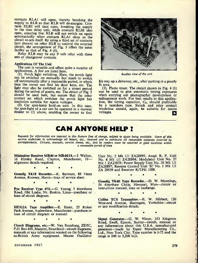
contacts RLA1 will open, thereby breaking the supply to RLE so that RLE will de-energise. Con- tacts RLB2 will then open, breaking the supply to the time delay unit, while contacts RLB1 also open, ensuring that RLE will not switch on again automatically when contacts RLA1 close as the circuit re-sets itself. By using a third set of contacts (not shown) on relay RLE to control the external circuit, the arrangement of Fig. 5 offers the same facility as that of Fig. 4 {b).
Relay RLE may be any 9 volt relay with three sets of changeover contacts.
Applications Of The Unit The unit is versatile and offers quite a number of
applications. A few are listed here. (1). Porch light switching. Here, the porch light
can be switched on manually but made to switch off automatically after a reasonable period, in which time the owner can find his door keys, etc. The light may also be switched on for a preset period during the arrival of guests, etc. The circuit of Fig. 5 should be used here, but ensure that the relay contact set which switches the porch light has insulation suitable for mains voltages.
(2). Car spot-lamp hold-on unit. In this case, the spot-light of a car can be operated in a manner similar to (1) above, enabling the owner to find
Another view of the unit
his way up a driveway, etc., after parking in a poorly lit area.
(3). Photo timer. The circuit shown in Fig. 4 (b) can be used to give automatic timing exposures when carrying out photographic development or enlargement work. For best results in this applica- tion, the timing capacitor, Q, should preferably be a tantalum type. Switch and relay contact insulation should, again, be suitable for mains voltages. □
CAN ANYONE HELP ?
Requests for information are inserted in this feature free of charge, subject to space being available. Users of this service undertake to acknowledge all letters, etc., received and to reimburse all reasonable expenses incurred by correspondents. Circuits, manuals, service sheets, etc., lent by readers must be returned in good condition within
a reasonable period of time
Minimitter Receiver MR44 or MR44/11.—J. Walker, 16 Himley Road, Clayton, Manchester, 11— alignment details required.
* • • •
Grundig TK18 Recorder.—K. Bartram, 89 Viney Avenue, Romsey, Hants—loan of service sheet.
* • * *
Pye Receiver Type 47X.—G. Young, 5 Hawthorn Road, Old Leake, Nr. Boston, Lines—purchase or loan of circuit diagram.
* * * •
HF/G2A Tape Amplifier.—E. Slater, 25 Roker Park Avenue, Audenshaw, Manchester—purchase or loan of circuit diagram or manual.
* * * *
Circuit Diagrams, etc.-—W. Van Rensburg, ZD5C, P.O. Box 418, Manzini, Swaziland—circuit diagrams, manuals or any information wanted on the following ex-British Army equipment. Master Oscillator
Unit No. 2 Mk 1/1 ZA28895: Ampl. R. F. Unit No. 4 Mk 1/1 ZA28894; Modulator Unit No. 27 Mk 1 ZA22878; Power Supply Unit No. 26 Mk 1/1 ZA28897; Remote Control Unit 'H' No. 1 Mk 1/1 ZA 29539 and Receiver R/TPH 1088.
• * * *
Grundig TK40 Tape Recorder.—D. W. Mannings, 54 Aberthaw Circle, Newport, Mon—circuit or instruction manual, loan or exchange.
* * * *
Collins TCS Transmitter.—E. W. Hibbert, 126 West-end Avenue, Harrogate, Yorkshire—circuit or any modification details.
♦ » ♦ »
Signal Generator.—G. W. Nixon, 243 Kingston Road, Ewell, Epsom, Surrey—circuit, manual or any information about this U.S.A. manufactured generator—made by Espey Manufacturing Co., Ltd., New York City. Type number is 1-72 and the range is 100 to 3,200 kc/s.
DECEMBER 1967 279
NEWS . . . AND .
Miniature Battery Charger
0>
A new miniature transistorised battery charger which is operated from the mains, has been introduced by Crowborough Electronics.
It is designed to re-charge the complete range of sub-miniature cells currently used in hearing aids, paging receivers, micro-miniature radios, radio-controlled models, photographic and many other types of equipment.
The charger is intended for nickel-cadmium re- chargeable cells such as the types 10DK, 20DK, and D151, but will also rejuvenate any of the miniature mercury or silver-oxide cells now in universal use, including the popular types 212, 312, 13, 575, 675, 401, and many others.
It is believed to be the only charger specifically designed for these sub-miniature cells, incorporating a double-wound mains transformer for absolute safety.
The transistorised circuit produces a constant charg- ing current which is independent of mains voltage varia- tions, battery voltages or polarity.
The unit is available in either 240 volt or 110 volt models, and includes a neon indicator lamp and 6 feet of mains lead.
Mains consumption is negligible, running costs being about 5/- a year.
Further details are available from Crowborough Electronics. 3 Rotherhill Road, Crowborough, Sussex.
Australis Oscar
The amateur radio satellite being prepared by Mel- bourne University is likely to be Oscar number 5, al- though no date has been fixed for its launching. Full details regarding orbit, etc. will be announced by the Sunday RSGB News Bulletin as soon after launching as possible.
This satellite will not be of the translator type, as were the two previous Oscars, but will transmit amplitude modulated signals on both 29.450 Mc/s and 144.050 Mc/s simultaneously. The telemetry channels will consist of tone signals, varying from 500 c/s to 1500 c/s. They can thus be deciphered by feeding the output of the receiver into an oscilloscope and comparing them with the signals from a calibrated audio oscillator. This, and the fact that one of the satellite's frequencies will be in the 28 Mc/s amateur band, will obviate the need for special v.h.f. receiving equipment, and should stimulate more interest in monitoring this satellite than in some of the more complex earlier ones.
Graphs are available correlating various parameters with audio frequency and special report forms will be available for recording observations.
Monitoring these amateur radio satellites is quite fascinating and is a very suitable project for clubs and school radio groups.
Full details can be obtained from W. Browning, G2AOX, Regional Director, Region 1. I.A.R.U. Project Australis, 47 Brampton Grove, Hendon, London, N.W.4.
NEXT MONTH'S ISSUE OF THIS MAGAZINE WILL CONTAIN A NEW ADDITIONAL FEATURE.
MAKE SURE OF YOUR COPY. PLACE AN ORDER WITH YOUR NEWSAGENT.
Cvny
'Gale force winds imminent in all areas'
280 THE RADIO CONSTRUCTOR

COMMENT
The International Short Wave League Comes of Age We congratulate the International
Short Wave League on obtaining its majority. The League was founded in October 1946 and has become, we believe, the largest independent organisation of its kind in the world.
We have an especial affection for the League as, when formed, it was associated with a journal we then published called S/iori fVave News, subsequently renamed The Radio Amateur and then finally incorporated into The Radio Con- structor.
In the December 1951 editorial of Short fVave News we said:—"It has always been our hope that we should one day be able to launch the ISWL off on its own course, so that it was quite independent of this journal. It is a bad policy to have any such organisation tied to a commercial project, because the criticism can very justly be made that the organisation is being run
to stimulate interest in the com- mercial concern's products " " A few months ago, the ISWL committee was formed and we now feel that the time is ripe for the ISWL to stand on its own feet as an independent organisation which is not in any way tied to a commercial concern. It can then manage its own affairs and finances and can become a truly independent organisa- tion "
In the same issue the League's officers expressed appreciation of all the help they had received from our organisation, and from its directors and staff, over the years.
They also expressed thanks " for the great amount of stock and equipment which has been handed over as part of the transfer arrange- ments "
The League was formed with three main objects;—(a) to bring to- gether the short wave enthusiasts
of the world regardless of race, creed or politics, to their mutual benefit; (b) to foster and promote inter- national goodwill through the medium of short wave radio interest; and (c) to provide facilities which will enable enthusiasts to carry out their hobby to the greatest advantage to themselves and their fellow enthusiasts. These objects have al- ways been adhered to.
During the past twenty-one years many small—and some not so small —radio clubs have come and gone and it would be wrong to suggest that the League's history has not been without difficulties at times However, it has a continuous record of progress behind it and can look forward to the future with confidence. There are 1,250 members in 70 countries, including such rare Dx spots as Thailand, Trucial Omen, Turks & Caicos Is, Afghanis- tan, Cayman Is.
Electrician's Kit for Christmas
The Bib Home Electrician's Kit, introduced recently by Multicore Solders Ltd., is now available as a Christmas gift. The kit can be supplied with a green and white tag, on which is printed a holly symbol with a slogan "With Best Wishes". There is space for the names of the sender and the recipient.
The Bib Home Electrician's Kit is ideal either as a personal or a business gift. It contains, in handy, compact form, virtually every item the handyman (or woman) requires to carry out electrical work in the home, workshop or garage. The kit is contained in an attractive plastics wallet, and has the following items:
Bib Model 8 Wirestripper and Cutter
Three Bib Flex Shorteners Ersin Multicore Tape Solder Insulating tape Screwdriver Fuse wire
The wallet is accompanied by a card bearing full instructions for use.
DECEMBER 1967
) or car contwmi WiRI STWPftS AMU CUTTM
281

p
HAND HELD 2-WAY RADIOPHONE
by F. G. RAYER, G30GR
This little transmitter-receiver, which must only be used by amateurs holding the requisite transmitting licence, is specifically designed to provide communication whilst carrying out
field strength tests and the like at a distance from the main transmitter.
This transmitter-receiver was made for 2-way conversation with the main station for tests
up to i mile or so. Valves were used rather than transistors for low cost, and to obtain immediate results without experiment or tricky adjustments.
The Circuit The circuit (shown in Fig. 1)
employs three B7G battery valves. Vi is a crystal controlled oscillator and feeds a telescopic whip aerial. Li is a coil for 40, 80 or 160 metre bands, as desired. It is attached to terminals and can be easily changed to suit the crystal. Vj is the receiver detector, employing the same coil,
The unit fitted in its case
Li, which is tuned by VCi on both Transmit and Receive. VRi adjusts G2 voltage to control volume. Vj is the modulator, being driven by Ti secondary and employing auto- bias from R4. The current for the carbon microphone is taken from the filament battery.
The Transmit-Receive switching is extremely simple. The 3-way switch, Si, has a central "Off" position, with no filaments on. With the switch at "Receive", l.t. is applied to V2 only, to provide reception. Placing the switch at "Transmit" supplies l.t. to Vi and V3 filaments, as well as to carbon microphone and primary of Ti.
Any available crystal for the 7-7.1, 3.5-3.8, or 1.8-2 Mc/s bands may be used. Coils for these three bands are described later, but only a single coil need be wound if operation is to be always on one band. This band will be that for which crystals are available, or which is used by the home trans- mitter or mobile transmitter with which aerial, field strength or other tests are to be made.
The receiver output is for medium or high impedance phones. A head- set, worn separately, is more con- venient than fitting an earpiece to the equipment. VRi is rotated from zero, as required, for suitable volume. Full rotation of VRi (maximum G2 voltage in V2) does not, incidentally, give best volume.
L2 is the primary of a small speaker matching transformer in- tended for use with a valve output stage, the 3fl secondary being un- used. Any component able to carry about 15mA should do. Tj was a
surplus carbon microphone trans- former. The small type of speaker transformer, as once used with battery pentode output valves and having a ratio of about 50:1, will also be satisfactory. The low resist- ance winding acts as primary. The microphone is an inexpensive surplus handset type.
The h.t. is 67.5V and the l.t. 1.5V. The h.t. and l.t. batteries were kept separate in a pack, so that any batteries to hand could be employed, if desired. Suitable batteries are the Ever Ready Alldry 35 for the 1.5V supply and the Ever Ready BI01 for the 67.5V supply.
Power And Range The power input to Vi is around
0.5 to 0.6 watt. The whip aerial fitted was nearly 3ft long when extended. At the main station the aerial is likely to be a dipole, end-fed wire, vertical, or other conventional system, and power input here will be up to 10 watts on 160 metres, and dp to 150 watts on the 80 and 40 metre bands. One of the various popular communica- tions-type or similar receivers will normally be used at the main station. In these circumstances, the range of the Radiophone is quite adequate. The receiving range of the Radio- phone can be enormously extended by fitting a small loop on Li, this being inserted between V2 anode and R3, with a 500pF capacitor from the junction of R3 and the loop to the l.t. negative line. VRi then acts as a reaction or regeneration control. If regeneration is absent, reverse the connections to the loop. The loop should have as few turns as possible.
282 THE RADIO CONSTRUCTOR

67-5 V
Telescopic aerial HT+
R
□ Phone c3 jack vc
V 3A4 3l< > 31
3V4
Mic. Ti 1
IT4 a Crystal
—i HT Off
Cs
1-5 V LT +
Fig 1. The circuit of the Radiophone
There is no significant difference to transmission when this reaction circuit is added.
For reports on field strength, as from a loaded vertical transmitting aerial or other system, a suitable receiving aerial is set up as far as practicable from the transmitting aerial. This receiving aerial may be vertical, end-connected horizontal, or a short or full-length dipole with centre feeder, as appropriate. Its output is fed to a tuned circuit, diode, and microammeter, upon which field strength readings are taken in the usual way. The 2-way Radiophone is intended to relay results of such tests or similar experiments, and not for actual signal strength tests..
Construction The prototype was assembled on
a piece of hardboard painted with shellac varnish.* Fig. 2 gives details of assembly and construction. All parts including the switch, VRi and VCi are on the same panel. Valveholder holes can be made with a fin punch as used for aluminium etc., or with a fin bit. There is not much free space, so it is wise to check the layout with the actual components first, especially those
♦ The "hot" terminal for Li and the mount- ing for the whip aerial should, preferably, be insulated from this material, which may ex- hibit excessive leakage under damp conditions. —Editor.
used for La and Ti, before cutting out the panel.
The microphone is mounted in a hole which provides a tight push fit, and leads are soldered to its rim and back contact. A tag is placed under one nut securing each
valveholder, and these tags are then wired together for the l.t. negative line, as there is no metal chassis. The bolt and tag anchoring C5, R4 and the h.t. negative lead are in- sulated from other circuits so as not to short-circuit R4.
Rcsistofs (All fixed values J watt 10%)
Ri lOOkn R2 2.2Mn R3 47kn R4 2200 VRi 250kO potentiometer,
linear track
Capacitors Ci 2,000pF, silver-mica C2 25pF, silver-mica C3 2,000pF, paper or plastic
foil, 150V wkg. C4 0.01 (xF, paper or plastic
foil, 150V wkg. C5 lOOxF, electrolytic, 6V
wkg. VCi 75pF, air-spaced, type
C804 (Jackson Bros.)
Inductors Li See text L2 Small valve output
transformer, secondary unused
Ti Carbon microphone transformer
Valves V! 3A4 V2 1T4 V3 3V4
Sockets Ji Phone jack socket 3 B7G valveholders 1 crystal holder
Crystal 160, 80 or 40 metre band crystal
Batteries 1.5 volt battery 67.5 volt battery
Switch Si Single-pole, 3-way switch
Miscellaneous Carbon microphone (see text) Telescopic aerial, about 3ft extended Insulated panel 2 knobs (for VRi and Si) 1 knob with scale (for VCi) Wire, battery cormectors, etc.
DECEMBER 1967 283

83/4"
A 3A4 3V4 Microphone
6BA terminals Crystal holder
Telescopic aerial
fM otr p \ 114 / VR vc.
LT + Phone jack To jack
C3 D> 1Q a* vc
VR, r\J
\ C5 Bolt
O^,
Microphone
HT+ LT- HT-
Fig. 2. Showing how the components are assembled and wired on either side of the panel
The battery cord consisted of thin flex, with black for h.t. negative, brown for l.t. negative, white for l.t. positive, and red for h.t. positive. A small metal clamp bolted near V3 secured the leads.
In Fig. 2, "R" and "T" are the Receive and Transmit contacts of the switch, whilst "S" is the slider of VRi. The spindles of VQ, VRi and the switch project through the front of the case and a small scale or dial for VQ is helpful. The switch knob should have "Receive", "Off" and "Transmit" positions marked on the case. A hole in the case allows the phone jack plug to be inserted, and an aperture is cut over the microphone position.
Tank Coils One coil is required for each band.
The coils have short wire ends and are mounted by securing these under 6BA terminals, as shown in Fig. 2. Ferrite cores were used for the large coils to reduce the size and number of turns. Other coils which can be made to resonate with VQ should also be satisfactory.
The 40 metre band coil has 40 turns of 24 s.w.g. enamelled copper
wire wound side-by-side on an insulated tube Jin in diameter and 13 in long. For 80 metres, a piece of ferrite rod of fin diameter and 2in length was used. The 80 metre coil has 21 turns of 22 s.w.g. enam- elled copper wire wound side-by-side, and the ends are secured with adhesive tape. The 160 metre band coil consists of 46 turns of 26 s.w.g. double cotton covered wire wound side-by-side on a fin by 2J-in ferrite rod.
Testing The current drain on Receive is
small, it being 0.05A from the l.t. supply and about 1mA to 2mA from the h.t. battery according to the setting of VR].
To check operation on Transmit, insert Vi and connect a meter in series with one h.t. lead. Use a coil and crystal for the same band. H.T. current is around 20mA with the circuit not oscillating, falling to 8mA to 10mA when VQ is tuned to produce oscillation. With the whip aerial extended, note the tuning position which corresponds to minimum h.t. current. This will be about correct for the crystal
and coil in use. VQ is tuned slightly off the minimum current position, in the usual way with crystal oscil- lators of the type used here, so that the oscillator starts reliably when switched on. Tuning is not very critical.
With V3 also inserted, and using a 67.5V h.t. battery, h.t. current should be around 15mA, or a little , higher, when VQ is tuned for near-minimum current. The bias across R4 will be about 3.5V. On Transmit, the l.t. drain is slightly over 0.3A. With the filaments off, there is a slight h.t. drain due to VRi, so the h.t. battery should be disconnected when the equipment is put aside for any length of time. Alternatively, an extra pole on the switch could be used to break the h.t. circuit when the Radiophone is switched off.
In normal use VC] can be tuned without an h.t. meter. Transmission will cease at settings of VQ (if any) which result in cessation of oscillation. If (he main station uses the same frequency, as is preferred, VQ can be approximately peaked for reception, although it does not tune sharply. To check transmission
284 THE RADIO CONSTRUCTOR

I1 M
The compact and neat appearance of the completed transmitter-
receiver
without an h.t. meter and at a dist- ance rotate VCi stating readings at intervals. Then switch to Receive and obtain from the main station a receiver S-meter report showing
the best setting. If this is noted, it can be used for the same crystal and coil in future.
Coils wound as described above were satisfactory for all the 40 metre
band, most of 80 metres and the low frequency end of 160 metres. On 160 metres and possibly on 80, the windings may have to be changed slightly to suit crystals near the band edges. An initial test will soon show this. It may be added that an input to Vi of 10mA at 60V equals 0.6 watt.
To give an idea of the ease of construction, the author's prototype was completed and tested in a single evening. The author's case, also made in this period, was strictly utility, consisting of thick card folded and glued into the re- quired shape. A more robust case can, of course, be readily made from thin wood, Paxolin sheet, or any other insulating material. __
"RUBBER ZENER" CIRCUITS
by G. SHORT
In this article, our contributor describes different techniques for obtaining zener controlled power supplies, the techniques being finall/ combined in a practical stabilised power supply circuit offering 0-24V at currents up to 1 A. It is important to note that the output transistor can operate at full rated dissipation for some output requirements and must be mounted, with good thermal contact, on a
large heat sink.
ZENER DIODES ARE CONVENIENT SOURCES OF stabilised voltage, but they ha,ve their limitations. Their voltage is fixed, and their output current
is limited by the permitted power dissipation of the diode. However, both these limitations can be overcome, and a single low-voltage, low-current zener diode can be made to provide a wide range of both voltage and current.
This is, of course, the function of stabilised power supply. But without going the whole hog and build- ing an elaborate stabiliser some of the advantages are obtainable by the use of circuits which "stretch" the voltage or current of the zener.
Increased Current The time-honoured way of getting more than the
prescribed current is shown in Fig. 1 (a). If, in the off-load condition, Rj allows the maximum rated zener current to flow, then when a load is connected nearly alj this current can go to provide base input current to the transistor. The output current is the
base current multiplied by the large-signal current amplification factor (hpE or "d.c. beta") of the tran- sistor. Thus, if the zener can pass up to 21mA, but will work with 1mA, up to 20mA can flow into the base before stabilising action fails. If hpE is 50, the load current can be 1A. Obviously, if we are to utilise such a large output TRj must be able not only to pass 1A but to provide the necessary ampli- fication while doing so. (This is just a rather laboured way of saying it must be a power transistor!)
A modification to provide variable voltage is shown in Fig. 1 (b). The output voltage can be varied from zero up to something approaching the zener voltage, and current amplification is also ob- tainable. But there is a limitation. Unless the slider of RV2 is at the end of its track, some resistance is put effectively in series with the base, and this reduces the available base current. This resistance reaches ^2 with the slider at the half-way point, and
4 voltage regulation suffers. For example, if RV2 is
DECEMBER 1967 285

+ V,,
■€J TR,
Low - i current Zener diode
Hiqh Current Output
O-
(a)
+^cc
rv2 7S
Zener diode
0 Short- Circuit Lamp
-o + Output
-
■L !
(b)
Fig. 1. Arrangements for "stretching" zener output: (a) increased current, fixed voltage; (b) increased
current and variable voltage
4kn) and the base current can reach 20mA, there is a loss of anything up to 20V, which is ridiculously large and probably exceeds the zener voltage any- way. So what happens is that the output voltage falls towards zero.
Despite this disadvantage, the circuit of Fig. 1 (b) is often a perfectly adequate means of obtaining a semi-stabilised variable voltage supply, so let's look at it a bit more closely before we go on to something more expensive. The maximum output voltage is the zener voltage (call it Vz less the base- emitter voltage of the transistor (usually called Vbe). If TR] is a silicon transistor, Vbe is 0.5-1.5V, and if it's germanium, 0.1—IV.
The diagrams follow the author's usual practice
of showing a positive upper rail and n.p.n. tran- sistors, but obviously one could use a p.n.p. trans- sistor with a negative upper supply line and reverse the zener. If only the stabilised output is required, it couldn't matter less which arrangement is used, since the output leads can be swapped round to provide positive or negative upper lines. But if the unstabilised supply is to be used simultaneously with the stabilised output it does matter, and one arrange- ment will be preferable, depending on whether the load requires a positive or negative upper rail. In the final practical circuit which appears at the end of this article, the common rail is negative and the stabilised and unstabilised rails are positive.
In the circuits now being described the transistor dissipation is fixed by the load. The worst case is when the load is very low and the current high. (These conditions are often met with in experiments, and are known as short-circuits!) Unless precau- tions are taken, the transistor then dissipates a power given by 1c x Vco and if the slider of RVz is at the top, Ib = Vcc/Ri very nearly and so Ic = hFE Vcc/Ri- Hence the maximum possible transistor collector dissipation is Pc = V2cchFE/Ri. If Vcc = 10V, R] = SOD, and hpE = 100, then Pc = 100 x 100/50 = 200W. This sort of power is inclined to make the transistor become a little on the warm side, and quickly. To guard against overcooked transistors, it is advisable to put a current-limiting resistance in the collector circuit. A lamp (as in Fig. 1 (b)) is convenient, since it drops little voltage at low currents and gives a warning light at high ones. The highest collector dissipation now occurs when the supply voltage is shared equally by the lamp and the transistor. Suppose the transistor can dissipate 5W safely. Then if Vcc = 10V, a collector safety resistance of 5D is indicated, and it will drop 5 V at 1A and dissipate 5W. Something like a 6V 6W
+ v
TR TRa
7S Zener diode
Output
I
I^F
Fig. 2. Compound emitter follower (Darlington pair) for improving regulation
286 THE RADIO CONSTRUCTOR

lamp will do. The price paid for safety is reduced output current.
Protective Diode What's the diode of Fig. 1 (b) for? It plays no
part in the stabilising action, in fact no part at all in the operation of the circuit. And it is reverse biased by the base-emitter voltage drop of TRj.
The diode is included as a result of bitter experi- ence, in the shape of the mysterious demise of TRi. The circuit worked all right one day, but not on the next day. TRj had developed a base-emitter short- circuit. Why? Base-emitter short-circuits are a common result of applying too big a reverse bias to the base-emitter junction of a transistor. But surely, there's nothing in Fig. 1 (6) to cause such a reverse bias? Quite right there isn't. But just suppose the stabiliser is being used to supply a piece of equip- ment which has a large smoothing capacitor between its positive and negative terminals. Now switch off the stabiliser, removing Vco The base of TRi is now at the same potential as the negative line, but the emitter is held positive by the charge on that large smoothing capacitor. If the resulting reverse bias (Veb) is big enough, the base-emitter circuit breaks down, and the capacitor discharges through it and RV2, burning out the transistor in the process. Unless, that is, the extra diode is there, in which case it just provides an easy discharge path which bypasses the transistor.
The diode isn't always necessary. Some transistors, such as the old-fashioned alloy types, will stand almost as much reverse voltage on their bases as on their collectors. Planar transistors have a Veb rating of 5V or less, and a diode is needed. Worst of all are diffusion transistors (AF115, etc.), which have Veb ratings of less than IV. Even a diode may not protect these, and they are not really suitable for use in this type of circuit.
Darlingtons A way out of the problems due to the resistance
inserted by RV2 is to use a transistor with an enor- mous hpE, so that practically no base current is drawn and so very little voltage is lost even when the load current is high. The best transistors now available have hFE approaching 1,000, but they are all low-power types (BC109, 2N3707, etc.). A way out is the compound emitter-follower or Darlington pair of Fig. 2, Here the effective hps is the product of the individual hps values. Very high values are obtainable. For example, if TRi were a high-beta planar with hFE = 500, and TR2 a power transistor with hFE = 50, the overall hps would be 25,000. For an output current of 1A, only l/25mA of base current need flow into TRj. Even if RV2 were lOOktl, only IV would be lost. The regulation of the output voltage is much improved, but the maximum output voltage is reduced, since there are now two base-emitter drops. The effect of RVj on the output resistance is reduced, and the zener current is now less dependent on the load current, which makes for better constancy of the zener voltage itself. If the supply is mains-derived, ripple on the 4- Vcc l'ne
Zener diode
Constant Load Current
-r
Fig. 3. Constant-current circuit. The current is determined by the zener diode and R2
can be vastly reduced by adding Q, and this also reduces the a.c. output impedance. Unfortunately, with certain combinations of transistors and loads, h.f. oscillation is then possible, but is easily sup- pressed by connecting a small capacitance C2 across the output.
Increasing The Output Voltage The above circuits are of no use if an output
voltage greater than the zener voltage is required. The author's answer to this problem is unusual, in that he first uses the zener to make a constant current generator, as in Fig. 3 This generates a constant current (i.e. independent of the load resis- tance) of (Vz = VbeI/Rz- Rather, it's constant until the drop in the load approaches (Vcc — Vz), when there isn't enough voltage left to operate the transistor.
To make use of this in a constant voltage supply, all you have to do is, in effect, make RV2 of Fig. 2 the load of the constant current source, as in Fig. 4 where it appears as RV4. Fig. 4 shows a practical design for 0 - 24V at up to 1A and incorporates the features previously discussed. If the B-5000 is mounted firmly, and with good thermal coupling, on to a really large heat sink, it will dissipate 25W, which is what it will have to do if 1A is drawn at a very low output voltage. But if high currents are only needed when the output voltage is high, the output transistor dissipates little power. In the pres- ent case, the dissipation falls off to almost nothing as the output approaches 24V, 1A, because under these conditions practically all the supply voltage is drop- ped across the lamp and the load. If more than 1A is drawn, the lamp will act as a (rather expensive) fuse. There is, of course, no reason why a 1A fuse or cut-out should not be installed as well as the
Continued on page 295
DECEMBER 1967 287
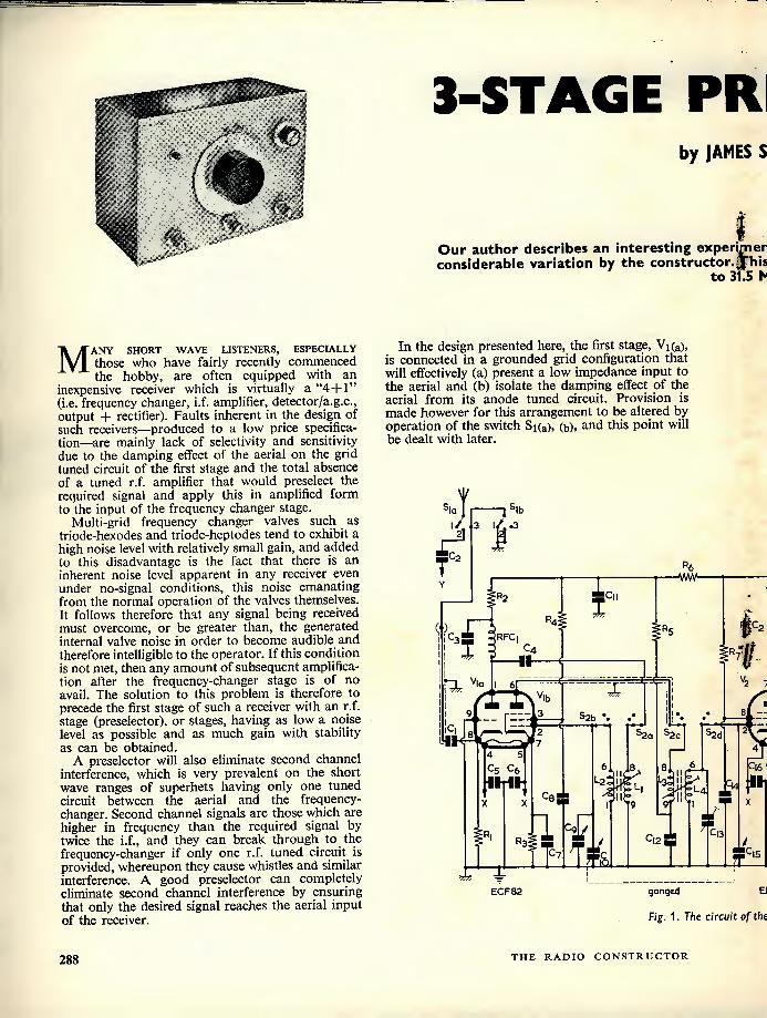
%
m
Many short wave listeners, especially those who have fairly recently commenced the hobby, are often equipped with an
inexpensive receiver which is virtually a "44-1" (i.e. frequency changer, i.f. amplifier, detector/a.g.c., output 4- rectifier). Faults inherent in the design of such receivers—produced to a low price specifica- tion—are mainly lack of selectivity and sensitivity due to the damping effect of the aerial on the grid tuned circuit of the first stage and the total absence of a tuned r.f. amplifier that would preselect the required signal and apply this in amplified form to the input of the frequency changer stage.
Multi-grid frequency changer valves such as triode-hexodes and triode-heptodes tend to exhibit a high noise level with relatively small gain, and added to this disadvantage is the fact that there is an inherent noise level apparent in any receiver even under no-signal conditions, this noise emanating from the normal operation of the valves themselves. It follows therefore that any signal being received must overcome, or be greater than, the generated internal valve noise in order to become audible and therefore intelligible to the operator. If this condition is not met, then any amount of subsequent amplifica- tion after the frequency-changer stage is of no avail. The solution to this problem is therefore to precede the first stage of such a receiver with an r.f. stage (preselector), or stages, having as low a noise level as possible and as much gain with stability as can be obtained.
A preselector will also eliminate second channel interference, which is very prevalent on the short wave ranges of superhets having only one tuned circuit between the aerial and the frequency- changer. Second channel signals are those which are higher in frequency than the required signal by twice the i.f., and they can break through to the frequency-changer if only one r.f. tuned circuit is provided, whereupon they cause whistles and similar interference. A good preselector can completely eliminate second channel interference by ensuring that only the desired signal reaches the aerial input of the receiver.
3-STAGE PR
by JAMES S
Our author describes an interesting experhner considerable variation by the constructor. |"his
to 31.5 P
In the design presented here, the first stage, Vi(a), is connected in a grounded grid configuration that will effectively (a) present a low impedance input to the aerial and (b) isolate the damping effect of the aerial from its anode tuned circuit. Provision is made however for this arrangement to be altered by operation of the switch Si(a), (b), and this point will be dealt with later.
rl 51
C2 T VVW
I cm T
« RFC | T
I C4
II <
a V|a -X-C 2 j X vib s2b *.
52d 4 5
C|5 Cs c6 flh US 11 IMt
L23l cm r& a Cs .s
c9 C|3 C|2 J T ■ /
I I c7
r± T
ECF82 ganged El
Fig. 1. The circuit of the
288 THE RADIO CONSTRUCTOR

RESELECTOR
IES S. KENT Cover Feature
MAMAM
rimental preselector which may be subjected to . Jhis 3-valve design covers the frequencies 1.67 31.5 Hc/s.
The stage providing most of the r.f. gain in this unit is that incorporating V2, this being an EF183 variable-mu frame-grid pentode having a mutual conductance of 12.5mA/V. The gain of an r.f. amplifier can be theoretically shown to be approxi- mately proportional to the mutual conductance of the valve used, and it can be seen therefore that the EF183 is ideally suited for such an application.
250V 50mA
1 C20 1
C25 ID
1 "14 C,9 c26
i ID
1 r c23 7 2 7
250V 24
6-3 R|3 CXitput 6-3V C|6C[7 IMI
C2I c22 AMI
I-5A PL,
Ris .
AC mams EFI83 6AT6
of the 3-stoge preselector
The last stage of the preselector is given by V3, a cathode follower consisting of a 6AT6 double- diode-triode connected here as a triode. This stage provides a voltage gain of slightly less than unity but owing to the high gain available from the preceding stages this small loss is of no consequence. The valve is intended to provide a correct impedance match, at all frequencies, between the first two stages of the preselector and the receiver input terminals.
From the points discussed it will be seen that the present design has the effect of providing a high r.f. gain with a low noise level, of eliminating second channel interference, and of providing a correct impedance match into the receiver.
Circuit The circuit is shown in Fig. 1 and from this it will
be seen that the aerial switching is arranged such that a choice is given of three positions; (1) aerial disconnected both from preselector and receiver; (2) aerial connected direct to receiver input and (3) aerial connected to preselector input.
At position 1 of Si(a) the aerial is disconnected from both inputs whilst Siq,) causes the preselector input to be earthed to chassis. At position 2 of Si(a) the aerial is fed direct to the receiver input, by- passing the preselector, via the capacitor C2; whilst Si(b) causes the preselector input to be still earthed. At position 3 of Si(a) the aerial is fed direct to the preselector input via the capacitor Cj, whilst at position 3 of Si(b) no connection is made.
The writer employs position 1 of the aerial switch to mute the preselector whilst carrying out calibra- tion checks and frequency measurements with a 100 kc/s crystal standard loosely coupled into the aerial circuit of the receiver. The 100 kc/s marker points may then be resolved with much greater ease since they are not masked by external signals. When operating, it is very convenient to be able to cut the input to the preselector in this manner. If a transmitter is installed, position 1 of the aerial switch may also be selected during trasmissions.
As specified, Si(a), (b) is a 2-pole 3-way component. A 4-pole 3-way miniature rotary switch with 2
DECEMBER 1967 289

RHr m
^ ♦ mWP *
:
Above-chassis view showing the positions of the main components
poles unused may, alternatively, be employed here, and such a component is readily available from suppliers. A 4-pole miniature switch was, in fact, used in the prototype.
When operating the preselector with Si (a), (b) in
position 2, where the aerial feeds directly to the re- ceiver, gain control Rio must be adjusted to its minimum gain setting.
With the preselector in use, signals are fed to the cathode of the triode section of Vi(a) via the capaci- tor Ci, this section of the valve operating in the grounded grid mode. The signals from Vi(a) anode are applied via the coupling capacitor C4, to 82(3) and thence to the primary winding of an aerial coupling coil selected by this latter switch, and shown as Li. Only one coil is shown in the circuit diagram, for reasons of clarity although there are, in fact three such coils, each covering a differing range of frequencies and switched into circuit by the sections of S2.
It will be noted that the valves have their heaters bypassed to chassis via 5,OOOpF capacitors. These capacitors completely eradicate any difficulties due to hum and also prevent unwanted r.f. couplings along the heater line. Resistor R15 maintains the heater circuit close to chassis potential. The bias supply for Vi(a) is obtained via the resistor Ri whilst the anode h.t. supply is derived via R2 and RFCj. The h.t. supply to Vi is decoupled from the remainder of the circuit by the resistor Re, capacitors Cn and C20 providing the requisite bypass to chassis.
The grid of Vi(b) is connected both to switch S2(b)> which selects the frequency range required, and also to C9 and Cio- The small value capacitor C9 is panel-mounted and acts as a trimmer control to bring this stage into resonance at the same fre- quency as the tuned circuit of the following stage. The second tuned winding is shown as having trim- mer C13 connected across it. There is one trimmer for each of the three coils actually fitted in the L3, L4 position, making three trimmers in all. The trimmers are adjusted, in conjunction with the iron
dust cores of the coils, so that the coils coyer the desired frequency ranges, these being approximately 1.67 to 5.3 Mc/s for Range 3, 5 to 15 Mc/s for Range 4 and 10.5 to 31.5 Mc/s for Range 5. The main tuning control is provided by the 2-gang capacitor Qo, C15.
Whilst dealing with the coils it should be men- tioned that, due to the high gain provided, some instability was experienced on Range 3 when Rio was set to offer maximum gain. Should a similar type of instability be apparent with other units built up to the circuit, it may be cleared by connect- ing a resistor between pin 6 of the Range 3 coil in the Li, L2 position and chassis, the value of the resistor being just sufficiently low to prevent oscilla- tion. In the writer's case the resistor fitted here had a value of S.lkfl. The resistor is not shown in the Components List or in the circuit diagram as it may not be required in all instances and its value is experimental.
Returning to the signal as it passes through Vi(a) and Vi(b), the combination C9, Qo and L2 selects the signal required and passes it to the grid of Vi(b). After amplification it is then fed to 82(0) and coil L3.
The h.t. supply for the anode of Vi(b) is obtained via R5 and L3 (bypassed to chassis by capacitor C12) and through switch 82(9). The screen grid supply is via R4, bypassed to chassis by capacitor Cg, and the required bias supply is provided by the components R3 and C7. It will be noted that the bias supply to Vi(b) has not been made variable. Con- structors preferring gain control of both stages may like to try the effect of connecting the earthy end of R3 to the centre tag (slider) of the gain control Rio- Some adjustment with respect to the value of R3 may probably be required, a higher value than that shown in the Components List being experi- mentally connected in the first instance.
The grid of V2 is connected to the variable capaci- tor Qs, the trimmer capacitor C13 and the tuned winding L4, this combination further selecting the required signal. The amplified signal at the anode of V2 is fed via coupling capacitor Qg to the grid of the cathode follower stage, V3. It should be noted here that pins 1, 3 and 9 of V2 are connected to- gether externally and taken, via Rg to the slider of Rio, which provides the variabk bias required for gain control. The cathode bypass capacitor is Qg. The anode h.t. supply is provided via Rg and RFC2, and the screen-grid supply via R7 with C14 as bypass capacitor.
The internal screen, pin 6, is connected direct to chassis as shown.
The 6AT6 double-diode-triode is connected into circuit as a triode, both diodes being strapped to chassis. Any other triode or double-triode, such as the ECC82 for example, strapped as a single triode could be used if to hand although some variation of component values associated with the valve would probably be required.
The output of the preselector is taken to the coax- ial socket via the components R13 and C24 from the cathode of this stage, h.t. supply to the anode
290 THE RADIO CONSTRUCTOR
Resistors (AH i watt 10% except where
Ri 150O R2 33kO R3 ioon R4 lOOkD Rs 5.6kn Re 4.7ka R? 33kn Rs 5.6kn R, 100a Rio 5kn, lin with switch Rn 5.6ka Rl2 470k H Rl3 Ikfl Rl4 3k D 2 watt Rl5 IMH
Valves Vi ECF82 (Mullard) Vz EF183 (Mullard) V3 6AT6 (Brimar)
Valveholders B9A (2 off ceramic with centre spigot)
B7G (1 off ceramic with centre spigot)
Coils Miniature Dual-Purpose (Denco Ltd.) Blue, Ranges 3, 4 and 5 (2 sets)
Capacitors Ci l,OOOpF ceramic C2 200pF silver mica C3 l,000pF ceramic C4 lOOpF silver mica C5 5,000pF ceramic Q 5,000pF ceramic C7 0.01 uF tubular (Mullard) Cg 0,01 u-F tubular (Mullard) C9 25pF variable, type C804 (Jackson Bros
Ltd.) Ci 0 31 OpF variable, 2-gang, type E (Jackson
Bros. Ltd.) Cn 0.1 nF tubular (Mullard) C12 0.1 (xF tubular (Mullard) C13 25pF trimmer (3 off) C14 0,01 aF tubular (Mullard) C15 310pF variable, ganged with Qo Cig 5,000pF ceramic C17 5,OOOpF ceramic Cig 0.01 ixF tubular (Mullard) C19 lOOpF silver mica C20 0.1 pF tubular (Mullard)
C21 5,0O0pF ceramic C22 5,000pF ceramic C23 0.02|xF tubular (Mullard) C24 0.01 txF tubular (Mullard)
*€25 32(xF electrolytic, 350V wkg. *C26 16[xF electrolytic, 350V wkg.
3, 4 and 5. (2 sets) (*Contained in single can with mounting clip)
Mains Transformer' Secondaries: 250V, 50mA;
6.3V, L5A; type 6BR10 (H. L. Smith & Co. Ltd.)
R.F. Chokes 2.5mFI type CHI (H. L. Smith & Co. Ltd.)
Knobs See text
Chassis 8^ x 5^ x 2iin (H. L. Smith & Co. Ltd.)
Panel x 7in
(H. L. Smith & Co. Ltd.)
Miscellaneous 5 fin grommets 1 fin grommet 2 3-way tag-strips
Dial and Drive 6:1 Slow Motion Drive, Part No. 4489, Jackson Bros. Ltd. (Home Radio Ltd. Cat. No: DL3A)
Panel Lamp Assembly Type LES (H. L. Smith & Co. Ltd.) 6.5V, 0.I5A
Rectifier 250V, 50mA, contact-cooled (H. L. Smith & Co. Ltd.)
Coaxial Sockets 2 off
Switches *Si(a), (b) 2-pole, 3-way
82(3). (b). (c). (d) 4-pole, 3-way S3 2-pole 1-way (ganged with Rio)
(*see text)
being via Rn, C23 providing decoupling to chassis. The cathode circuit for V3 is completed by the
aerial input components in the receiver and it is, therefore, necessary for the receiver aerial input circuit to provide a d.c. path for the cathode current of V3. This will be automatically provided in con- ventional receivers by the coupling winding for the aerial coil. It is essential, for safety reasons, that
the receiver has a chassis isolated from the mains. The output of the preselector must, on no account, be directly coupled to a receiver whose chassis is con- nected to one side of the mains supply.
The power supply is an integral part of the unit and includes mains transformer Tj, this being a fully shrouded chassis mounting component. T1 is followed by a contact-cooled metal rectifier
DECEMBER 1967 291

I/A* I'M
— |3/4*- 9l/2*-
l3M*
^ PL, ,09
2[I2
I* 1_
RIO.S3
13/4* —t- 2^4*
-* cIO.cl5
(a)
-01/2- -23/4*
lkS|
-13/4*
2>/2* 51/2
13/4*
i'/S*
2l/8*-
FRONT
2l/8*-
(b) - 01/2*-
2l/0*-
(O
21/0-
2l/4*
Fig. 2 (a). Drilling dimensions for the front panel (fa). Top view of the chassis, showing valveholder positioning
(c). The three holes needed on the rear apron
292 THE RADIO CONSTRUCTOR

and the smoothing components R14, C25 and C26- The heater supply has the panel-mounted pilot
lamp PLi connected across it and a twisted pair is then taken to each valve in turn. Connection to the a.c. mains supply is via the on/off switch S3, this switch being an integral part of the gain control Rio-
Construction Drilling points for the front panel are shown in
Fig. 2 (a) and the front cover illustration provides a visual indication of the completed panel. The final position of the spindle for the 2-gang capacitor will depend on the actual component used but the dimensions shown in the diagram will be correct if the specified part (see Components List) is used. Drilling details for the dial cursor are provided with the dial drive specified.
Suitable knobs can be obtained from H. L. Smith & Co. Ltd. The main requirement here is that the three lower knobs should be of a small diameter type, so that the centre knob fitted to S2 will clear the lowest part of the dial. Panel-Sign transfers could be used on the front panel where desired and the panel itself painted or cellulose sprayed with the chosen colour. As shown on the front coyer, no such embellishments were made at the time of photographing, although these have since been added by the writer.
Fig. 2 (b) shows the positions of the three valve- holders. The appropriate holes should be initially drilled and then cut out with a chassis cutter; B9A for V] and V2, and B7G for V3. When mounted, V1 valveholder should have pin 4 nearest the front, V2 valveholder should have pin 1 nearest the front and V3 valveholder should have pin 2 nearest the front. It will be found helpful to fit a 3-way tag-strip (centre tag earthed) under the rear mounting nut of Vj and V2 valveholders.
The holes for the mains transformer and its leads may be marked out by using the component itself to indicate the positioning required. The two chassis holes for the leads from the transformer should be fitted with fin grommets, the mains input leads to the primary passing through the hole nearer the front. Three further holes with fin grommets are required in the chassis, two for the connections to the fixed vanes of Qo, C15, and one for the twisted 6.3 volt pair to the pilot lamp. The two tuning capacitor connection holes are on the V] side of this component, and it should be noted that C10 is the section of the 2-gang capacitor which is nearer the panel. The hole for the pilot lamp wire is immediately beneath the pilot lamp holder when the chassis and panel are assembled. The contact- cooled rectifier is mounted below the chassis at the rear, midway between the output socket and the dual electrolytic capacitor C25, €26- The latter is fixed to a side apron in the position shown in the photograph of the underside.
The positions of the coils depend upon the type of switch employed, and this point is discussed later.
It will be noted that the front panel has a yin overhang either side of the chassis itself and this was dqne so that the unit, once completed, could be
Below-chossis view of the completed preselector showing the positions of the coils, smoothing capacitors
and contact-cooled rectifier
inserted into a wooden shelf adjacent to the receiver with the sides and top of the front panel secured by means of small chromium-domed wood screws into the wooden surround. Alternative methods, such as the fitting of the preselector into a metal case, may require different measurements to the panel over- hang than are shown here.
Fig. 2 (c) shows the chassis rear apron drilling details, hole A taking a fin grommet for the a.c. mains power input lead. The earth wire of this lead (green) should be connected to chassis, and the red and black wires connected to the correct tags of the on/off switch, S3, integral with the gain control Rio- Hole B is for the preselector/aerial output, this being fitted with a coaxial socket. Hole C is for the aerial input to the preselector, and is also fitted with a coaxial socket.
Coil Positioning An important component in the preselector is the
switch S2. It is necessary here to have a switch with individual wafers which are well spaced from each other. Such switches are expensive, but the writer was able to locate a surplus item available from
-H. L. Smith and Co. which meets present require- ments admirably and which retails at a fraction of the cost of a new, specially designed, component. He is informed that H. L. Smith and Co. have ample stocks of this switch for those who may require to purchase it for building the unit. The switch has three wafers spaced as shown in the photograph of the chassis underside. The rear wafer has two separ- ate switch sections mounted on a single quadrant of the Paxolin, and the switch should be mounted so that this quadrant is towards the Vj side of the chas- sis. On the front wafer the bottom (farthest away from the chassis underside) single pole 3-way section is employed as 82(0)- On the centre wafer, the single pole 3-way section nearer Vi is employed as S2(b)- On the rear wafer, either of the single pole 3-way
DECEMBER 1967 293

sections nearer Vj is employed as S2(a)- The single pole 3-way section on the rear wafer nearer V2 is used as S2(d). Constructors are strongly advised to use a continuity meter when identifying the switch contacts as it is easy to make mistakes. The switch knob selects Range 3 when turned fully clockwise, with Range 4 in the central position. Some of the switch sections on the H. L. Smith component are left unused.
Readers employing an alternative switch are recommended to use a 3-wafer component with approximately the same switch section positioning.
The coils take up positions as close to whatever switch is employed as will allow for convenience in wiring. The three coils for L] and L2 are on the Vi side of the switch and the three coils for L3 and L4 are on the V2 side of the switch. In both instances the Range 3 coils are nearest the panel, the Range 4 coils are in the centre and the Range 5 coils are at the rear. The three trimmers for C13 have their non-earthy tags soldered direct to pin 6 of the coil concerned, the earthy ends connecting to a chassis bus bar wire running alongside the coils.
One important point which should be observed when wiring up is that the centre spigots of all three valveholders should be connected to chassis. The
writer found it helpful to solder a small tinplate square, about i by ^in, to the centre spigot and pin 6 of V2, this straddling the valveholder between the grid and anode pins. This provides a measure of screening, and the chassis ends of components such as Cig, C17, etc., may be conveniently soldered to the bottom edge of the tinplate square. Obviously, the tinplate square must not short-circuit to any of the valve pins.
The illustrations of the above and below chassis views of the preselector provide adequate informa- tion on the method of construction and the siting of the main components but in view of the (to the beginner) complexity of the switch wiring, this design is nor recommended as a unit that the com- parative novice should undertake to construct.
Connection to the receiver should be via a short length of coaxial cable, the metal braiding of which should be connected to the chassis, via the coaxial plug, of both the preselector and the receiver.
In operation, the preselector has been found to perform to the writer's satisfaction over the entire range. In common with most units of this type efficiency above the 21 Mc/s band tends to fall off a little, the answer at these frequencies being, of course, a converter unit. pB
"APPLICATIONS OF
MICRO-ELECTRONICS"
A symposium entitled "Applications of Micro-electronics" will be held in Birmingham on 27th March 1968. It will be supported by an exhibition of equipment appropriate to the subject from 26th to 28th March. The emphasis of this event will be on the point of view of designers, manufacturers and users of equipment. A series of eight papers will each discuss the design factors featured in a particular application where micro-circuits have been found to offer a favourable solution. In particular compari- sons will be drawn between equipment designs using discrete components and those using micro- circuits. Together the papers will cover a wide field of application ranging from computers to industrial electronics and measuring instruments. The discussion will be directed towards an impartial exchange of views on the economic, manufacturing and performance aspects of equipment.
The arrangements are jointly in the hands of the IEE South Midland Centre, Electronics and Control Section and the West Midlands Section of the Institution of Electronic and Radio Engineers.
Further details of the programme and registration forms may be obtained In December from the Hon. Secretary of the Organising Committee;—
G. K. Steel, B.Sc., D.I.C., M.I.E.E.. Electrical Engineering Department, The University of Aston in Birmingham, Gosta Green, BIRMINGHAM 4.
Enquiries from those wishing to exhibit equipment would also be welcomed.
294 THE RADIO CONSTRUCTOR
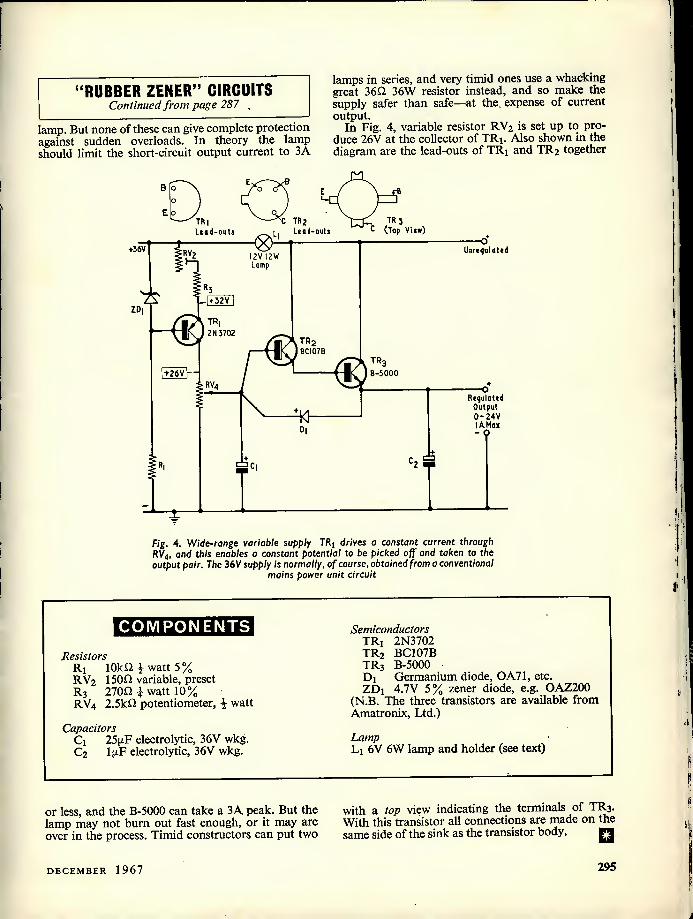
"RUBBER ZENER" CIRCUITS Continued from page 287
lamp. But none of these can give complete protection against sudden overloads. In theory the lamp should limit the short-circuit output current to 3A
lamps in series, and very timid ones use a whacking great 36n 36W resistor instead, and so make the supply safer than safe—at the. expense of current output.
In Fig. 4, variable resistor RV2 is set up to pro- duce 26V at the collector of TRi. Also shown in the diagram are the lead-outs of TRi and TR2 together
+36V Unrcqulatcd
. TR3 C (Top View)
C TR2 TR| Lead-outs Lead-outs
12V 12 w Lamp
+ 32V
TR| 2 N 3702
TR2 BCI07B
TR t26V B-5000
c, S
o Requlaled
Output 0- 24V I A. Ma* -
Fig. 4. Wide-range variable supply TR, drives a constant current through RV4, and this enables a constant potential to be picked off and taken to the output pair. The 36 V supply is normally, of course, obtained from a conventional
mains power unit circuit
COMPONENTS
Resistors R] lOkfl Jr watt 5% RV2 150n variable, preset Rj 270^ i watt 10% RV4 2.5kfl potentiometer, i watt
Capacitors Ci 25(j.F electrolytic, 36V wkg. C2 l(iF electrolytic, 36V wkg.
Semiconductors TRi 2N3702 TR2 BC107B TR3 B-5000 Dj Germanium diode, OA71, etc. ZDi 4.7V 5% zener diode, e.g. OAZ200
(N.B. The three transistors are available from Amatronix, Ltd.)
Lamp Lj 6V 6W lamp and holder (see text)
or less, and the B-5000 can take a 3A peak. But the lamp may not burn out fast enough, or it may arc over in the process. Timid constructors can put two
with a top view indicating the terminals of TR3. With this transistor all connections are made on the same side of the sink as the transistor body. n
DECEMBER 1967 295

SEQUENTIAL FLASHER
FOR CHRISTMAS LIGHTS
By R. J. CABORN
Intended for the experimenter with experience of relays and their operation, this article describes a sequential light switching circuit which can operate as
many lights as are required.
SEQUENTIAL LIGHT SWITCHING CIRCUITS ALWAYS provide an interesting novelty. This is particu- larly true at this time of year when they may be
used, for instance, to control the lights around the Christmas tree. Alternatively, the sequential lights may be used to flash a message in sections, each letter or part of the message being illuminated in turn. A sequential switching system is also attrac- tive for shop premises, where it may be used for advertising purposes.
The sequential switching circuit described here is capable of controlling as many lamps as is desired, each lamp requiring a relay with two normally- open contact sets and an electrolytic capacitor to provide a delay. Two further relays, one with one normally-open contact set and one with two norm- ally-closed contact sets, together with two further electrolytic capacitors, are needed for terminating the sequence.
It is assumed that the reader is familiar with relay circuits and their operation. No specific relay type is specified since, provided the type employed has a coil resistance of 500fl or more, and is capable of energising at some 12 volts or less, the choice is not at all critical. It should be mentioned, however, that the energising voltage just referred to is applicable for a d.c. supply of around 24 volts. If a d.c. supply of higher voltage is used, the relays employed may energise at voltages higher than 12. As will be gath- ered after the functioning of the switching circuit has been described, its flexibility enables a wide range of variations to be made in operating voltages and components. A further point is that all the relays used need not be of the same type. Different types can be very easily accommodated by varying the capacitance and resistance for each relay coil circuit.
The Circuit The sequential switching circuit appears in the
accompanying diagram, this being drawn to accom- modate four lamps. The circuit uses the "detached"
method of presentation, in which each relay coil is represented by a rectangle designated by a letter over a figure. The letter identifies the relay, and the figure the number of contact sets. Each contact set, which may appear anywhere in the diagram, is then identified by its letter followed by a serial number. Thus, the rectangle designated B/2 is the coil of relay B, and its contact sets are indicated as B1 and B2. All contact sets are shown in the position they take up when the associated relay is de-energised.
Initially, switch Si is open. When this switch is closed, Si(b) applies the lamp supply to the lamp switching circuit and S](a) applies the positive side of the relay energising supply to the normally-closed contacts Fl. The d.c. supply is now fed to relay coil A/2 via resistor Ri. Due to the presence of Q across the coil, relay A takes a short time to energise. When it energises, contacts A2 complete the lamp supply circuit to lamp Li, which then becomes illuminated.
At the same time, contacts AI apply the positive relay supply voltage to coil B/2 via Rz. After a delay due to the presence of Cz across its coil, relay B energises. Its contacts B2 close and cause lamp Lz to be illuminated, whilst its contacts B1 allow the positive relay supply voltage to be fed to coil C/2 via R3.
Relay C energises, after a delay due to capacitor C3. Its contacts Cz cause lamp L3 to be illuminated and its contacts C1 apply the relay positive supply voltage to R4 and coil D/2.
After a further delay, due to C4, relay D energises. All the lamps are now illuminated and the first part of the sequence is over. Contact D1 applies the positive supply voltage to relay E and, after a delay, this relay energises. Its contacts El then apply the positive supply vcltage to the coil of relay F.
After a period, relay F energises, whereupon its contacts F2 break the supply to the lamps, which are then abruptly extinguished. At the same time, contacts Fl also break the positive relay supply circuit to relays A to E and, after a short delay due
296 THE RADIO CONSTRUCTOR

KL
^ Bl ^ O ^ Dl ^ El
6 6+ Relay supply
? sc Sc [=□
©'■i Lamp supply
S|a-|b - ganged
The circuit of the sequential flasher, employed for controlling four lamps. Component values are discussed in the text
to the charged capacitors connected across them, these de-energise. When relay E de-energises, its contacts El break the positive supply to relay F which, after a short period, also de-energises. Its contacts F2 complete the lamp supply circuit, but no lamps light since the relays A to D are now de- energised. Also, contacts Fl re-apply the positive relay supply to the energising circuits for relays A to E and, after a delay due to the presence of Cj, relay A energises and the next sequence starts.
It is necessary to employ two relays, E and F, instead of one to terminate the sequence for the following reason. If one relay were employed its normally-closed contacts would have to break its own energising circuit and, with the electrolytic capacitor across its coil, its armature would tend to take up a position which alternated between the just open and just closed condition. With the two relays, relay F does not break its own energising circuit. Instead, it breaks the energising circuit to relay E, and there is a short delay before contacts El open to de-energise relay F. A further point is that, after contacts Fl open, the short delay given before relay E de-energises gives the capacitors Q to C5 time to discharge sufficiently for their relays to de-energise. A further delay to allow C2 to C5 to become adequately discharged is given by Cg across coil F/2 and Rj and Q.^The de-energise period of relay F should always be longer than the de-energise period of relay A and this point can be covered by making Cg larger in value than Ci (assuming both relays are the same type). The de-energise period of relay F should also be longer than that of relay D, otherwise there is a risk of relay E energising after contacts Fl close again.
Summing up the operation of the circuit, the sequence proceeds in the following manner. On closing S] there is a short delay after which relay A energises and lamp L] lights up. After a further delay relay B energises and lamp L2 lights up. The process continues to relay D being energised and all the lamps being alight. All the lamps remain illuminated for a relatively long period until relay E and then relay F energises. The lamps are then abruptly switched off and relays A to E de-energise independently. After a pause given by capacitor Cg discharging and, then, the subsequent delay due to Ri and Q, all the capacitors C2 to C5 are adequately discharged and the sequence recom- mences with relay A energising and lamp Lj lighting up.
Delay Periods The delay period before relays B to E energise can
be of the order of a second or so whereupon the whole sequence takes about 8 seconds to complete. This is an appreciable time and the resultant display will be quite effective. The energising delay required in relay A need be only sufficient to ensure that C2 to C4 are adequately discharged before relay A energises at the start of a new sequence. The ener- gising delay for relay F may be about 2 to 4 seconds.
The d.c. supply for the relays should have a voltage at least twice the energising voltage of any relay. The required series resistance and parallel capacitance needed for each relay may then be found experimentally. The series resistance must first be determined, and this should have a value which just allows the relay to energise reliably when the supply is applied. Varying values of capacitance are
DECEMBER 1967 297

then tried across the coil until the desired delay is obtained. As a guide, a P.O. 3000 relay with a 50011 coil has an energising delay of about 1 second when the series resistor is 750fl, the parallel capacitor is SOOixF and the supply voltage is 17. A capacitance of about 1,000 to 2,000:j.F is required if this relay is employed for relay F. In general, lower values of capacitance will be required for relays with coils having higher resistance. The capacitors must, of course, have working voltages equal to or greater than the voltage appearing across the relay coil to which they connect.
The accompanying diagram shows 4 lamp-
controlling relays, but the circuit application may be employed for fewer or more lamps and relays. It is merely necessary for one contact of one relay to apply energising voltage to the next, and for one contact of the last lamp-controlling relay to apply energising voltage to the first of the two end relays which terminate the sequence.
As a final note, if the lamp supply is obtained from the mains, all the contact sets in the lamp switching circuit must have insulation suitable for mains voltages, and all precautions against acciden- tal shock when handling the equipment must be observed. n
TRADE
REVIEW . . .
TRIO
COMMUNICATIONS
RECEIVER
MODEL 9R-59DE
a transmitter This Japanese communications receiver, recently released in this country by Lasky's Radio Ltd., is of pleasing appear-
ance—see illustration—and exhibits a performance that is well up to the manufacturer's specifications (given below). It was apparent that, with the model supplied to us, a lot of forethought and planning had gone into the design of this receiver and we found several unusual features not listed by the makers. Of these, that which appealed to us most was the inclusion of a pre-wired valveholder which only required the fitting of an OA2 (150V) stabiliser tube to provide the separate oscillator (J 6AQ8) with a stabilised h.t. supply. In addition to this very easy modification we noted a pre-punched section of the chassis (valveholder and crystal holes) in which the purchaser can very rapidly assemble a 100 kc/s crystal oscillator. Moreover, the r.f. and i.f. gain control has an integral switch at the maximum gain position to which may be wired the 100 kc/s oscillator valve cathode as an on/off control—a circuit for this being given in the receiver handbook. Again, provision is made on the rear chassis apron for the mounting of a coaxial aerial input socket as an alternative to the normal screw type.
The circuit comprises 8 valves and 7 diodes, printed circuit techniques being used for the r.f. and i.f. strips. Two mechanical filters ensure a high degree of selectivity. One half of the 6AQ8 oscillator is unused and the manufacturer suggests, in the receiver handbook, that this could be employed as a cathode follower providing the input to the mixer stage.
Of particular appeal to us are the bandspread scales, these being accurately calibrated for each amateur band from 3.5 to 28 Mc/s once the main tuning dial has been set to the required position. Immediately after switching on, we found the calibration of the receiver to be only a few kc/s out throughout the entire tuning range, the true frequencies being slightly low in frequency of those shown on the dial. Provision is made for correct calibration by easy access to the coilpack through holes under the receiver cabinet, a printed guide to cores and trimmers being affixed alongside. A few moments spent in lining-up with a 1 Mc/s crystal oscillator soon corrected matters.
The electrical bandspread and the main tuning dials also have graduated 0-100 scales for logging and frequency reading purposes. Thus, the bandspread 0-100 scale represents, on 40 and 80 metres, 5 kc/s per division; ori 15 and 20 metres, 20 kc/s per division; and on 10 metres, 50 kc/s per division. In this manner, the frequency of any amateur station may be read off the bandspread dial.
The noise limiter circuit was found to be extremely effective, the spiky Loran pulses on Top Band being completely smoothed out when the ANL was brought into use.
W/ m
RIO
The Trio Communications Receiver Model 9R-S9DE. The receiver is supplied complete with alternative front mounting feet and a headphone plug. Provision is made on the rear apron of the chassis for remote control when used with
298 THE RADIO CONSTRUCTOR

The S-Meter may be accurately aligned by means of a 500n potentiometer mounted on the chassis rear apron, the method of doing this being explained in the receiver handbook. The meter gives readings up to 60dB above S9 for which- ever mode of reception the function switch is set.
The product detector (6BE6) readily resolves s.s.b. transmissions and a panel-mounted trimmer to adjust bfo frequency provides selection of upper or lower sideband reception of these signals.
On the BO speaker output circuit, provision is made for the speaker to be muted when a headphone plug is inserted into the headphone jack.
As received, the a.c. mains input selection switch is set to 230V 50 c/s, but this point should be checked by the pur- chaser before connecting the receiver to the mains supply—a large warning notice to this effect is included inside the packing case lid. The receiver is extremely well-packed and is protected with a tough clear plastic cover ensuring trouble- free transit. "
The well-designed panel layout is finished in light grey, to contrast with the dark grey of the perforated case the latter ensuring adequate ventilation.
Owing to the careful design and liberal use of screening frequency drift, after the initial first few minutes after switch- ing on, was found to be completely absent. In fact, with the model supplied to us, and with the OA2 stabiliser fitted, we found that complete frequency stabilisation was reached in a few minutes.
Needless to say, this receiver stays in our possession! ,, ^The ,Trio 9R-S9DE may be obtained from Lasky's Radio Ltd., 3-15 Cavell Street, Tower Hamlets, London. E.I at 36 Gns plus 12/6 carriage and packing.
Trio Communications Receiver Model 9R-59DE Manufacturer's Specifications
Frequency Ranges: Band A 550—1600 kc/s Band B 1.6—4.8 Mc/s Band C 4.8—14.5 Mc/s Band D 10.5—30 Mc/s
Bandspread: Calibrated electrical Aerial Input: 50—4000 impedance Audio Power Output: 1.5 watts Sensitivity: 2pV for 10dB s/n ratio at 10 Mc/s Selectivity: ± 5 kc/s at —SOdB (±1.3 kc/s at 6dB) B.F.O. Frequency: 455 kc/s ±2.5 kc/s
Speaker Output: 4 or SO Headphone Output: Low impedance Power Consumption: 45W Valve Line-Up: Vj 6BA6 r.f. amplifier
V2 6BE6 mixer V3 | 6AQ8 oscillator V4 6BA6 1st i.f. amplifier V5 6BA6 2nd i.f. amplifier V(j 6BE6 product detector V7(a) i 6AQ8 B.F.O. V7(b) i 6AQ8 1st a.f. amplifier V8 6AQ5 audio output
Diodes 1—7: S-Meter, noise limiter, a.m. detector, a.g.c. voltage doublet and rectifier, h.t. rectifiers. □
A NEW BENCH SOLDERING STAND
A neat new soldering aid is now stand for a soldering iron combined separately.
The soldering stand holds the iron at a convenient angle in an insulated socket which retains the heat of the tip. The iron is further protected by a cylindrical metal guard.
The tip cleaning sponge is kept moist from a water reservoir beneath it. It is shaped to allow quick one-stroke cleaning and, if regularly used, will help to prolong the life of the iron by preventing corrosion.
The price of the Lerloy Soldering Stand is 41/0d.
The Cleaner alone is 14/6d.
available from Henri Picard & Frere Ltd. It consists of a holding with a tip cleaning sponge. These cleaners can also be supplied
DECEMBER 1967 299

Switch-On
Delay for TV
D. B. Hulse, A.M.Inst.E
In some of the older TV receivers employing a valve h.t. rectifier, damage can occur if the receiver is switched off then switched on again when the h.t. reservoir capacitor has discharged but the rectifier cathode is still at full emitting temperature. This article describes a neat delay circuit which ensures that switch-on under these
conditions is automatically delayed
Recently, an argument took place in the writer's home between his two young daughters, aged 6 and 2$, as to whether the
TV set should remain on, or go off, following the completion of a programme. The elder decided that it should be switched off, and this she did. With a lightning reaction from the younger the set was immediately switched on again, with the result that both internal fuses (mains and h.t.) were blown, and the h.t. rectifier valve rendered useless.
Subsequent to the two culprits being packed off to bed, and the later fitting of a new valve and fuses, the writer decided that some form of delay subsequent to switching on the set could possibly prevent future damage. After a search through the spares box, and checking out several designs, the very simple but effective circuit shown in the accompanying diagram was made up.
Circuit Operation Switch Si is the existing mains on-off switch on
the set. With Si switched on a current flows through the thermistor THi and the parallel branch com- prising the relay coil and Ri via relay contacts RL-2. The initial (cold) resistance of the thermistor and the parallel resistance of the relay coil and Rj ensure that the voltage across the relay coil is below the minimum pull-in value. As the thermistor warms up, due to the current flowing through it, its resistance decreases which, in turn, increases the Voltage across the relay coil. After a time the voltage across the coil is sufficient to energise the relay, and its contacts then perform three functions. First, power is switched through to the receiver; second,
lb TV mains input circuit
I ^ L o 8 RL-2
RL
c\ .\, RL- TH
200-250V AC. mains
Receiver chassis
The circuit of the delay unit. Switch Si is the on-off switch already fitted in the receiver. The numbered points identify the pins of the octal valveholder into which the relay fits. Relay contacts are shown
in the de-energised position
resistor Rj is open-circuited; and third, the thermis- tor is short-circuited. The reason for the second and third functions is that the resistor and thermistor are no longer required after the timing is completed. It is essential, in the case of THi, that this component be allowed to cool in order to regain its initial high resistance. If the receiver is later switched off and then on again, the mains supply is not applied to its circuits until the delay period has once more elapsed.
The relay employed is a Keyswitch (Omron) type MK2P, which plugs into an octal valve base. It is fitted with 2 sets of changeover contacts, and the coil is rated at 230 volts, 2.5mA, 50 c/s. In the circuit diagram, the numbers 1 to 8 relate to the pin connections on the octal base.
The thermistor used had an initial resistance at room temperature (around 20oC) of 5kfl, This coincides with the Brimar type CZ2 characteristic, and other manufacturers' data may also coincide. Delay times can, in any case, be varied by altering the value of Ri.
The writer employed a 10 watt resistor for Ri but, in view of the fact that after several repeated operations the temperature of this resistor increased very slightly only, it should be possible to use a lower wattage type (e.g. 3 to 5 watts).
It is emphasised that the above components were to hand. No doubt other types of a.c. relay could be used providing the initial voltage across the coil is
COMPONENTS Ri 3kfl (see text) THj Thermistor type CZ2, or equivalent RLi Relay type MK2P, 230 VAC energising
(Keyswitch Relays Ltd., Cricklewood Lane, London, N.W.2)
Octal valveholder
300 THE RADIO CONSTRUCTOR

well below the pull-in value. Alternative relays may necessitate a change in the values of Ri and/or HTi. The relay specified may be obtained from the suppliers quoted in the Components List.
With the author's components the delay given when initially switching on the receiver from cold is 20 to 25 seconds. If the receiver is switched off after having reached full operating temperature then immediately switched on again, the delay is around 10 seconds due to the increase in ambient temperature around the thermistor. During this 10 second period (and during the last 10 seconds or so of the initial switching-on delay) relay chatter increases in volume until the relay energises. This appears to be the only objection to the circuit, but it can be overlooked in view of the fact that it is only present for about 10 seconds. Indeed, the writer's family and friends find it quite amusing.
As already stated, the intention was to provide a delay circuit of a simple nature compatible with reliable operation. The circuit does suffer one inherent disadvantage, this being given by the fact that very little or no delay is available if the set is switched off and immediately switched on just after the relay has energised, because the thermistor will not then have cooled sufficiently. (Provided that the thermistor is cool by the time that the h.t. rectifier reaches emitting temperature, this should not be too great a disadvantage.— Editor.)
One final point relates to the thermistor. It is well to position this component as far away from direct heat as possible, due to its inherent response to temperature. Also, all components must, of course, be fitted inside the TV cabinet, since their connections are at mains potential. □
CARTOON
H
U
C
K
L
£
10kQ: "How are you?" 1 'JO; "Not so good, my resistance is low"
RADIO CONSTRUCTOR
BUILD SOME BE TOE
FASCINATING DESIGNS
FEATURED EACH MONTH
NEXT MONTH'S
SPECIAL FEATURES
RADIO CONTROLLED FIELD MONITOR
VERSATILE MULTIMETER
SILICON TRANSISTOR REFLEX T.R.F.
MAKE SURE OF YOUR COPY! 1
To
NEWSAGENT
Please reserve/deliver RADIO CONSTRUCTOR (2/6), dated January, on sale 1st January and continue every month until further notice.
Name
Address
DECEMBER 1967 301

IN LAST MONTH'S ISSUE WE CONTINUED OUR DISCUS- sion of phase-splitters by dealing with the "Paraphase" and see-saw circuits, together with
several developments of the latter. This month we complete our examination of phase-splitters by describing the Schmitt phase inverter, after which we will introduce the subject of negative feedback.
The Schmitt Phase Inverter A further type of phase-splitter, commonly referred
to as the Schmitt phase inverter, is illustrated in Fig. 1. In this diagram we have two similar triodes (which may, in practice, consist of a double-triode) sharing the common cathode resistors R2 and R3. R2 functions as a common cathode bias resistor and, because it passes the cathode current of both valves, has half the value which would be used by either triode operating as a voltage amplifier on its own.
goes positive, thereby providing the second output signal.
We have seen, then, that by applying a positive- going signal to the grid of Vj we obtain a negative- going output signal at the anode of Vj and a positive- going output signal at the anode of V2. Similar reasoning will demonstrate that a negative-going input signal results in a positive-going output signal from Vj and a negative-going output signal from V2. The circuit provides, in consequence, two out-of- phase outputs and so meets the first requirement of a phase-splitter.
The two outputs will have very nearly equal amplitudes if the triodes have a high amplification factor and if R3 has a high value of resistance. In practice, an ECC83 would represent a good choice for Vj and V2, and R3 should have a value of the order just mentioned. When R4 and R5 have exactly
UNDERSTANDING
f IkVlC I
! Schmitt Fhafe Inverter
ffl
by W. Morley
Bias is applied to the grid of Vi by way of Ri and to the grid of V2 by way of Rg. These two resistors may have values of the order of IMfl. The lower cathode resistor, R3, has a much higher value than R2 and may be, typically, 20k Q or more.
Resistors R4 and R5 are nominally equal in value and form the anode loads for Vi and V2. They may have the values normally provided as anode loads for these valves when working as voltage ampli- fiers. Cj, C3 and C4 are a.f. coupling capacitors. C2 has a low reactance at audio frequencies and could be, typically, 0,1 uF.
If a positive-going input signal is applied via Cj to the grid of Vi this valve draws greater current, with a consequent increased voltage drop across R4, and across R2 plus R3. Thus, the anode goes negative (providing one of the output signals) whilst the cathode goes positive.
Since the cathode of V] connects to the cathode of V2, the latter goes positive also. At the same time, the potential on V2 grid remains fixed, due to the presence of Cj. A cathode going positive relative to its control grid has the same effect as a control grid going negative relative to its cathode, and so the positive excursion of V2 cathode results in a reduc- tion of anode current in this valve. Less voltage is therefore dropped across R5 and the anode of V2
equal values the output from V2 anode is always slightly lower than that from Vi anode. The ampli- tudes can be balanced in practice by making R5 some 2 % to 4 % greater than R4.
Although the cathodes have an unbypassed cathode resistor, there is not the same heavy degen- eration as occurs with the split-load phase-splitter because, in this case, almost equal currents of oppo- site phase flow in the resistor. The gain offered by the circuit for either output is, in fact, about half of the gain which would be provided by one of the triodes used as a normal voltage amplifier. Both output impedances are equal.
Two advantages of the Schmitt phase-splitter are that it is inherently self-balancing, and that there are no coupling capacitors between the two valves which could cause unbalance at the lower audio frequencies.
An interesting version of this phase-splitter is shown in Fig. 2, this being due to Mullard Limited.* The circuit of Fig. 2 functions in the same basic manner as that of Fig. 1, and it should be noted that the grid of the right hand triode has the same bias potential as the grid of the left hand triode by way
* "Circuits For Audio Amplifiers" (and other Mullard publications) published by Mullard Limited.
302 THE RADIO CONSTRUCTOR

HT+
"4! "s:
-ll-
Outputs
Fig. 1. The Schmitt phase inverter C|
Ah
1*2
*6 -VM-
"X"
of the IMQ resistor connected between them. The main difference between Fig. 2 and Fig. 1 is that the input coupling capacitor is omitted, and the grid of the left hand triode connects directly to the anode of a preceding EF86 voltage amplifier pentode. Al- though the grids of the two triodes are now con- siderably positive of chassis, the current which flows in the valves is limited by the cathode and anode resistors. The cathodes take up a potential positive of the two grids which provides a bias corresponding to the current which flows in the cathode resistor, and the circuit is thereby self- biasing. Nevertheless, it is still desirable that the voltage on the grids be such that the bias obtained brings the two triodes on to the centre of their linear working characteristics. In the Mullard application the EF86 is so operated that its anode is
about 80 volts positive of chassis, the h.t. potential applied to the upper ends of the two triode anode loads being 410 volts.
As a note on terminology it should be mentioned that the Schmitt phase-inverter is also referred to as the cathode coupled phase-splitter.
Negative Feedback We have referred, in a number of earlier articles in
this series, to amplifiers having positive feedback. In most of the examples we have considered the positive feedback is sufficient to cause the amplifier to become an oscillator. We have also seen positive feedback applied, by means of a reaction circuit, to a grid leak detector. In this instance, the degree of positive feedback applied to the detector (which functions also as an amplifier) is capable of being
HH-
ISOkn: t I80kn
Fig. 1 Another version of the Schmitt phase inverter. The two 180k O anode load resistors are matched to within 5% and it is recommended that the following 470kQ grid resistors for the push-pull output valves (not shown here) be simi- larly matched. (Acknowledgement:
Mullard Limited)
Anode of
EF86 fa
ECC 83
0-5>jF HI—
05>iF HI—
To output grids
82kn< l O 25pF
"X"
•DECEMBER 1967 303

controlled so that the detector is just short of going into oscillation, whereupon the positive feedback very nearly cancels out the "losses" in the tuned circuit feeding the detector, and this tuned circuit becomes capable of exhibiting a very high effective Q with correspondingly high slectivity and sensitivity.
With negative feedback we apply a fraction of the output signal to the input of an amplifier in anti- phase. That is, the signal fed back is 180° out of phase with the input signal to the amplifier.
Fig. 3 (a) illustrates a straightforward amplifier to which no negative feedback is applied. If a signal input voltage is fed to the two input terminals in this diagram, an amplified signal voltage appears at the output terminals. Plus and minus signs have been added at the input and output terminals, these indicating the polarities of the signals during one half-cycle of the input signal.
In Fig. 3 {b) we connect resistors Ri and R2 in series across the output terminals, the voltage across Ri now being inserted between the lower in- put terminal and the corresponding input point of the amplifier. Again we have plus and minus signs to indicate signal polarities and we now add three terms to indicate signal voltage amplitudes. These are Vin, to indicate the signal voltage applied to the input terminals of Fig. 3 {b)\ Vg, to indicate the signal voltage applied to the amplifier proper (the subscript "g" infers an input control grid circuit); and Vout, to indicate the signal voltage at the out- put. It will be seen that, due to the polarity of the fraction of the output signal which appears across Ri, an out-of-phase signal voltage is inserted in series with Vin and the input of the amplifier, with the result that Vin must always be greater than Vg. In other words, to achieve the same output voltage the signal applied to the input terminals in Fig. 3 {b)
+
Input Amplifier Output
+
(a)
T Input Vin
R| 9
t t -
Amplifier R2i
X
Vout Output X
(bt fig. 3 (0). A simple amplifier without negative feedback (b). By adding R] and Rj in the circuit shown here, negative feedback is provided between the input and
output terminals
must always be greater than the signal applied to the input terminals in Fig. 3 (a). By adding resistors Ri and R2 in the manner shown in Fig. 3 (b), we have introduced negative feedback, with the consequence that the overall gain—from input to output termin- als—has been reduced.
The loss of gain resulting from negative feedback is, of course, a disadvantage but, as we shall show next month, the negative feedback provides a num- ber of important advantages which considerably outweigh this disadvantage, particularly with respect to audio frequency amplifiers. Indeed, the major practical application of negative feedback is to improve the performance of a.f. amplifiers, or of other low frequency amplifiers which are required to provide a low-distortion output.
Before concluding this month, a simple and interesting mathematical exercise will demonstrate one of the results of adding negative feedback to the amplifier of Fig. 3 (a) so as to give the circuit of Fig. 3 (b).
The voltage gain of the amplifier proper is V0ut divided by Vg and we may demote this by the letter
A. Thus: a _ Yo^ A- Vg
or, Vout = AVg Since Ri and R2 form a fixed potentiometer, the
fraction of the output voltage appearing across Rj is Ri/(Ri + Ra)- Let us call this fraction n. The voltage appearing across Ri is thus nVout-
V, across Ri, so:
Vin= Vg + nV0Ut.
Substituting for Vout from our previous equation, we get:
Vin = Vg + nAVg
= Vg(l +nA).
Thus, Vin has to be (1 + nA) times greater than Vg to achieve the same output; or, the negative feedback has caused Vin to be divided by (1 + nA) before application to the amplifier proper. The expression (1 + nA) is sometimes referred to as the feedback factor.
It follows that the overall gain with feedback is A divided by (1 + nA), i.e.
~ • A Overall gam = 1 + nA
If the product of A and n is large we then en- counter the remarkable fact that, regardless of the gain of the amplifier without feedback, the overall gain with feedback is always nearly equal to 1/n. For instance if n is 1/20 (whereupon 1/n = 20) then for A = 2,000 we have an overall gain of 19.8, for A = 1,000 we have an overall gain of 19.6 and for A = 500 we have an overall gain of 19.2.
Next Month In next month's issue we shall continue with the
subject of negative feedback. □
m is greater than Vg by the signal voltage
304 THE RADIO CONSTRUCTOR

n
□ o
o o o
your
work
As usual, Christmas finds Dick and Smithy heavily embroiled in the extra repair work which always appears at this time of the year. Fortunately, they manage to spare the last hour of the day to discuss the latest addition to the Workshop test equipment— Smithy's ingeniously designed stabilised power
supply.
Talk about this being the season ^ for burying the hatchet," snorted a perspriing
Dick as he wrenched viciously at the controls of the record-player on his bench. "What Vd like to do right now is to bury my hatchet in the head of the geyser at the factory who dreamed up these push-on knobs that can't be flaming well pulled off again!"
At last the final knob came free, whereupon Dick feverishly removed the record-player chassis from its cabinet and grabbed his testmeter prods.
From which statement and occur- rence two facts may be deduced. First, that the time was such that a general demeanour of benevolence and good will was expected from Dick. And, second, that Dick was far too pushed to provide it.
If we now add the information that the date was December 23rd and that the Workshop was to be closed on the morrow all becomes clear. As occurred every year just before Christmas, the Workshop was completely inundated with television sets, radio receivers and record-players which had decided to become faulty immediately prior to the Great Day. Thus, whilst the general public outside gradually relaxed before settling down for the Christmas holiday, and even the Christmas Card counter at Wool- worth's showed signs of diminishing business after the three months it had been open, Dick and Smithy laboured mightily at the repair of the domestic electronic equipment which was essential for the festivities at the neighbouring Yuletide family firesides.
Stabilised Supply But, as must inevitably happen,
diligence and hard labour won through, and in the latter part of the afternoon the Serviceman and his assistant suddenly found them- selves staring unbelievingly at a 'For Repair' rack which was now completely empty.
"Stap me," said Dick in- credulously, as he tottered back wearily to his stool, "we've done it!"
"We have indeed," agreed Smithy, mopping his brow. "I never thought we'd have been able to get all that lot cleared out before packing-up time. And it's a bit too near Christ- mas right now for me to particularly relish doing any overtime."
The pair fell silent for some moments as they recovered from the Herculean labours of the morn- ing and afternoon. Dick glanced at the Workshop clock, then brightened.
"Well, there's one good thing, anyway," he remarked. "We've still got an hour to go yet!"
"Have we?" commented Smithy, surprised. "We must have been fixing those sets a lot faster than 1 d realised. Oh well, if we've got an hour to spare we can take things easy for a while. That hour also gives me a chance to introduce something new to you."
"Something new?" "That's right," said Smithy, as
he reached into the cupboard at the side of his bench. "Now, what do you think of this?"
Dick looked curiously at the small chassis which Smithy placed care- fully on his bench. This sported, on its front panel, a large red terminal, a large black terminal, a toggle switch, and two control knobs, whilst on its top surface were two
power transistors mounted on a heat sink, a mains transformer and a number of small components wired up neatly on a groupboard.
"What is it?" "This," announced Smithy
proudly, "is the Workshop Stabilised Power Supply. I've been knocking it up at home during odd periods and I just managed to finish it off last night. Up till now, we've been too busy today for me to show it to you and explain how it works."
"Stabilised power supply, eh?" said Dick thoughtfully. "What out- put voltage does it give?"
"There's a continuously variable control which provides an output from about 0.5 to 16 volts," replied Smithy. "Which is just the job for working with transistor gear."
"That should be jolly useful," remarked Dick, interested. "What's the maximum output current?"
"Now that," pronounced Smithy, "is where we come to the crafty bit! With the circuit I've used here it s possible to adjust the power unit so that'it offers any maximum output current you like up to 300mA. It gives a well regulated output for currents below the figure you've set it up for, but it simply refuses to pass any current above that figure. This means that, if you're using the unit for experimental work, it's impossible for the equipment con- nected to it to suffer ^any damage due to too high a supply current. On this particular model I've fitted a 2-way switch to select maximum output currents of 100mA and 300mA, which should be adequate for our requirements in the Work- shop. But the circuit can be easily altered to give any other maximum output currents, up to 300mA, that you may want."
Dick looked impressed. "Blimey, that is something," he
said. "What happens if I set it up to 10 volts at a maximum current of 300mA and draw, say, 275mA from it?"
"You get 10 volts." "And if I draw 300mA from it?" "The output voltage drops to
zero. But if you reduce the load current to 275mA again the output immediately reverts to 10 volts."
"Gosh! It sounds as though you could even short-circuit the output terminals of the unit with a piece of wire!"
"You can," replied Smithy cheer- fully. "The output voltage will then merely drop to zero and 300mA will flow through your piece of wire. If the power supply had been set to 100mA, then 100mA will flow through the wire. I must add
DECEMBER 1967 305

SOOjjF 25V wkg
D,-D4 type ICXD/l-25 TR| ,TR3 on heat sink
type H1I
Output
7 47 kn 'Mw
D6 17V AC. | Ifevolt •05 Zener
L
ZL 6 300n bkn TR2 ACYI9
' "3 OC36 1 I lOOOpFi
25V wkg
270n '/4w TR| a
OC 36
m
& 72 w I20n 5 ;; '300 • lOO 74 w DOOOO^ mA mA*
['Mw TR TR|,TR3
Fig. 1. The .circuit of Smithy's stabilised power supply. The output current is limited to 100mA or 300mA according to the bosition of $2. The values of R2 and R3 have to be found experimentally, the process being explained in the text
that all this will happen regardless of the output voltage to which the power supply had been set up before you put the short-circuit on."
"But surely," protested Dick, "short-circuiting the output terminals must cause some damage in the power supply."
"Not in this power supply it won't," replied Smithy, giving the chassis a fond paternal pat with his hand. "This one's designed to give a specific maximum output current which cannot be exceeded. Re- capping on what I said a little earlier the unit is, in consequence, capable of protecting any equipment which is connected to it. If, for instance, you have a gadget which, when working correctly, draws 80mA, then you switch the power supply to 100mA maximum output current. Should something go wrong with the equipment and it starts to draw an increased current, then the power supply will automatically ensure that the increased current cannot exceed 100mA."
Constant Current Device "I'd certainly like to know how
this supply of yours works," said Dick enthusiastically. "Is it all your own design?"
"Not entirely," replied Smithy modestly. "I was inspired to dream up the principle from two of G. A. French's recent 'Suggested Circuits'. I combined two separate ideas from these in the present unit. Incidentally, this power supply unit makes quite an interesting little project for the
home-constructor, as it's quite simple to put together and layout is not at all critical. As a matter of fact I bought some of the parts from a home-constructor supplier myself, because they aren't normally en- countered amongst ordinary servic- ing spares. Anyway, here's the circuit of the power supply if you'd like to have a look at it."
Smithy produced a sheet of paper from his drawer and laid it on the. surface of his bench. Dick walked over, squatted down beside the Serviceman, and concentrated on the circuit Smithy had drawn out. (Fig. 1).
"Well," he pronounced, after a minute's diligent study. "I'm O.K. from the a.c. mains input up to the bridge rectifier and Q. But after that I'm stymied, mate!"
"Fair enough," chuckled Smithy. "I'll go through the circuit with you then;"
"Pray do." Smithy frowned. "You're getting very polite all
of a sudden," he remarked suspici- ously. "What's happening?"
"I'm just beginning to get the Christmas spirit."
Smithy settled himself more com- fortably on his stool.
"I must confess I'm beginning to feel a bit that way myself," he remarked lazily. "And it's nice to ■ think that it's Christmas Eve to- morrow and there's no more work to do. Anyway, let's get back to this circuit of mine. You've already said that you're O.K. up to Cj,
the 1,000|j.F electrolytic, so I'll just go very briefly through that bit. The a.c. mains is applied via the on-off switch Si to the mains transformer, this having a secondary voltage of 17. The secondary voltage is passed to the bridge rectifier given by Di to D4, and a rectified d.c. voltage then appears across the l,000|xF reservoir, Q."
"That's fine," said Dick. "It's the stuff after Q that worries me!"
"In that case," replied Smithy, "we shall now proceed from Cj in an easterly direction; whereupon we arrive at the current limiting and voltage stabilising parts of the circuit. I'll deal with the current limiting part first, whereupon I must ask you to cast those beady eyes of yours upon TRi. This is an OC36 power transistor which is operated in the grounded base mode."
"Hang on a minute," inter- rupted Dick. "That rings a bell somewhere! Didn't you tell me some time ago that a grounded-base transistor offers a constant collector current ?"
"I did," confirmed Smithy. "Actually, it was two months ago, when we were nattering about transistor a.f. output stages in mains- driven equipment. Now, TRi has its base held at a fixed potential by way of D5. D5 is a silicon diode and it is caused to pass about 50mA in the forward direction by Ri. So a nice steady voltage of around 0.6 is dropped across D5 and the base of TRi is continually maintained at this potential relative to the positive
306 THE RADIO CONSTRUCTOR
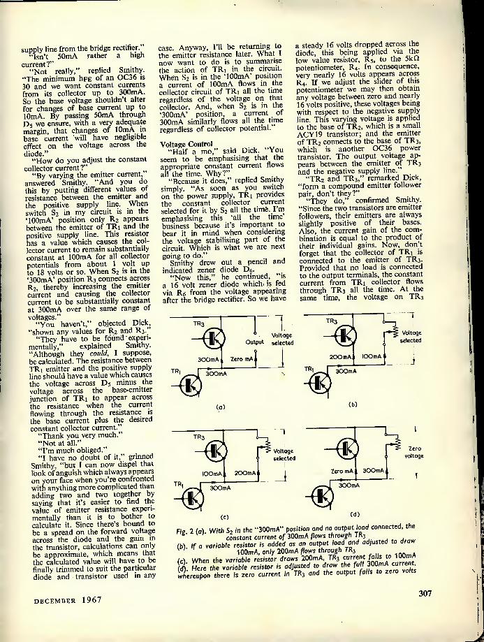
supply line from the bridge rectifier." "Isn't 50mA rather a high
current?" . "Not really," replied Smithy.
"The minimum hpE of an OC36 is 30 and we want constant currents from its collector up to 300mA. So the base voltage shouldn't alter for changes of base current up to 10mA. By passing 50mA through Dj we ensure, with a very adequate margin, that changes of 10mA in base current will have negligible effect on the voltage across the diode."
"How do you adjust the constant collector current?" „
"By varying the emitter current, answered Smithy. "And you do this by putting different values of resistance between the emitter and the positive supply line. When switch S2 in my circuit is in the TOOmA' position only R2 appears between the emitter of TRi and the positive supply line. This resistor has a value which causes the col- lector current to remain substantially constant at 100mA for all collector potentials from about 1 volt up to 18 volts or so. When S2 is in the '300mA' position R3 connects across R2, thereby increasing the emitter current and causing the collector current to be substantially constant at 300mA over the same range of voltages."
"You haven't," objected Dick, "shown any values for R2 and R j '
"They have to be found expen- mentally," explained Smithy. "Although they could, I suppose, be calculated. The resistance between TRi emitter and the positive supply line should have a value which causes the voltage across D5 minus the voltage across the base-emitter junction of TRi to appear across the resistance when the current flowing through the resistance is the base current plus the desired constant collector current."
"Thank you very much." "Not at all." "I'm much obliged." "I have no doubt of it," grinned
Smithy, "but I can now dispel that look of anguish which always appears on your face when you're confronted with anything more complicated than adding two and two together by saying that it's easier to find the value of emitter resistance experi- mentally than it is to bother to calculate it. Since there's bound to be a spread on the forward voltage across the diode and the gain in the transistor, calculations can only be approximate, which means that the calculated value will have to be finally trimmed to suit the particular diode and transistor used in any
case. Anyway, I'll be returning to the emitter resistance later. What 1 now want to do is to summarise the action of TRi in the circuit. When S2 is in the TOOmA' position a current of 100mA flows in the collector circuit of TRi all the time regardless of the voltage on that collector. And, when S2 is in the '300mA' position, a current of 300mA similarly flows all the time regardless of collector potential.
Voltage Control "Half a mo," said Dick. "You
seem to be emphasising that the appropriate constant current flows all the time. Why?"
"Because it does," replied Smithy simply. "As soon as you switch on the power supply, TRi provides the constant collector current selected for it by S2 all the time. I'm emphasising this 'all the time business because it's important to bear it in mind when considering the voltage stabilising part of the circuit. Which is what we are next going to do."
Smithy drew out a pencil and indicated zener diode Dg.
"Now this," he continued, "is a 16 volt zener diode which is fed via Rg from the voltage appearing after the bridge rectifier. So we have
a steady 16 volts dropped across the diode, this being applied via the low value resistor, R5, to the 5k O potentiometer, R4. In consequence, very nearly 16 volts appears across R4. If we adjust the slider of this potentiometer we may then obtain any voltage between zero and nearly 16 volts positive, these voltages being with respect to the negative supply line. This varying voltage is applied to the base of TR2, which is a small ACY19 transistor; and the emitter of TR2 connects to the base of TR3, which" is another OC36 power transistor. The output voltage ap- pears between the emitter of TR3 and the negative supply line."
"TR2 and TR3," remarked Dick, "form a compound emitter follower pair, don't they?"
"They do," confirmed Smithy. "Since the two transistors are emitter followers, their emitters are always slightly positive of their bases. Also, the current gain of the com- bination is equal to the product of their individual gains. Now, don't forget that the collector of TRt is connected to the emitter of TR3. Provided that no load is connected to the output terminals, the constant current from TRi collector flows through TR3 all the time. At the same time, the voltage on TR3
Voltage Output selected
TR3
Zero mA 300mA
300mA
TR3 1
Voltage selected 1 1
200mAi lOOmA 1 !
(a)
300mA
(b)
1 I TR3/^l
Voltage ' selected
lOOmA I ZOOmA t
¥
300mA
(c)
Zero mA , 300mA
Zero voltage
300mA
(d)
Fie. 2 (a). With S, in the "300mA" position and no output load connected, constant current of 300mA flows through TR3
(b) If a variable resistor is added as an output load and adjusted 100mA, only 200mA flows through TR3
(c) When the variable resistor draws 200mA. TR3 current falls to 100mA (<fl Here the variable resistor is adjusted to draw the full 300mA current, whereufxin there is zero current in TR3 and the output falls to zero volts
DECEMBER 1967 307

95mA 280mA
set to lOOmA
200 300 iOO
Output voltage
Output current ( mA)
Fig. 3. Output voltage-current characteristic for any voltage selected by R4. With $2 set to "300mA", there is a drop of some 0.2 to 0.3 volts from zero current to 280mA, after which the voltage abruptly drops to zero at 300mA
emitter is always about 0.3 volts positive of the voltage on the slider of R4 due to the base-emitter voltage drops in TR2 and TR3. In consequence, the output voltage of the unit can be varied by adjusting R4."
"I suppose," said Dick reflectively, "that using two emitter followers after R4 instead of just one gives you better voltage regulation."
"Oh, definitely," agreed Smithy. "The current flowing in R4 must always be much greater than the current changes in the base it supplies. Otherwise, the reference voltage provided at R4 slider would change by an unacceptable amount due to varying base currents. As you'll see in a moment, we expect TR3 to give a steady output voltage for emitter current changes from zero to 300mA. Assuming a mini- mum gain in this transistor of 30, this argues that there can be cor- responding changes in base current of the order of 10mA. The ACY19 in the TR2 position has a minimum gain of the order of 80, with the result that the maximum current changes in its base circuit can be of the order of 10mA divided by 80, which is 125u.A. A steady current of about 3mA flows through R4, which is quite sufficient to swamp out changes as small as 125u.A. Another factor which makes the use of two transistors attractive is that the output impedance at TR3 emitter is approximately equal to the input impedance at TR2 base divided by the overall current gain. This enables you to have output impedances which are, theoretically, exceptionally low."
But Dick's thoughts were now running on a different level.
"How can you have varying emitter currents in TR3?" he asked. "You said just now that the constant current from TRi collector flows through TR3 all the time."
"No I didn't," retorted Smithy.
"What I said was that the constant current flows in TR3 provided that no load is connected to the output terminals. When we connect a load, the current in TR3 changes ac- cordingly."
"This bit is puzzling me rather," confessed Dick. "What exactly does happen when you connect a load?"
"Let's assume," said Smithy in reply, "that S2 is set to the '300mA' position and that R4 is adjusted to give any convenient output voltage. A current of 300mA then flows through TR3. (Fig. 2 (a)). We next connect a variable resistor to the output terminals to act as a load and set it up to consume a current of 100mA. (Fig. 2 (6)). The output voltage remains unaltered, but 100- mA now flows through the variable resistor load and only 200mA flows through TR3. We next adjust the variable resistor so that it consumes 200mA (Fig. 2 (c)). Again the output voltage remains unaltered but, this
OC36
time, 200mA flows in the load and 100mA flows through TR3. If we then adjust the variable resistor to consume 300mA, all the current will flow in it and none will pass through TR3 at all. (Fig. 2 {d). In practice, the output voltage will commence to fall as the output current reaches some 280mA or so, and at 300mA the output voltage will be zero."
"Well, that's neat," commented Dick. "In other words, TRi just sits there in its corner preventing everything in its collector circuit from passing more than 300mA."
"Exactly," said Smithy, reaching for his pen and scribbling on the edge of his circuit diagram (Fig. 3). "The output voltage-current curve at all voltages selected by R4 is like this. The output drops by only some 0.2 to 0.3 volts as current increases from zero to around 280mA After 280mA the curve abruptly falls to zero voltage at 300mA. You get the same abrupt drop near 100mA, of course, if S2 should be in the TOOmA' position."
Total Current "There's something else," cut in
Dick suddenly, "which I've just realised!"
"What's that?" "It's the current drawn from the
bridge rectifier and Q," said Dick. "Once you've put S2 in the position you want, this current remains fixed regardless of load current because it consists of the selected constant current plus the currents passing through D5 and Dg."
"True enough," agreed Smithy. "As a result, the only changes in
Mica washers
o
o
OC36 Heat sink Fig. 4. In Smithy's unit the OC36's are insulated from the heat sink with mica washers and insulating bushes. The heat sink should be mounted with ribs
vertical and with clear access to the air for cooling
308 THE RADIO CONSTRUCTOR
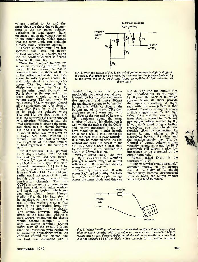
Additional capacitor lOpF 25V wkg.
Negative
I I supply line
C2 w To base
06 of TR2
Fig. 5. With the circuit of Fig. 1, control of output voltage is slightly sluggish. If desired, this effect can be cleared by reconnecting the positive plate of Cj to the lower end of R4 track, and fitting an additional 10p,F capacitor as
shown here
voltage applied to Rp and the zener diode are those due to fluctua- tions in the a.c. mains voltage. Variations in load current have no effect at all on the voltage applied to the zener circuit, which means that the zener diode can maintain a really steady reference voltage."
"There's another thing, I've just spotted," said Dick. "If there's no load connected, all the dissipation for the constant current is shared between TRi and TR3."
"Now that," replied Smithy, "is rather an interesting feature of the circuit. If, for instance, no load is connected and the slider of R4 is at the bottom end of its track, then about 16 volts appears across TR3 and only about 2 volts appears across TRj. So, virtually all the dissipation is given by TR3. If, on the other hand, the slider of R4 is right at the top end of its track there is only a very low voltage across TR3 and nearly 18 volts across TR], whereupon almost all the dissipation has to be given by TRi. With R4 slider in the middle of its track the voltages across TRi and TR3 are about equal and each has to provide the same amount of dissipation. Without a load, the total dissipation is always the same, and since this is shared between TRi and TR3 it becomes attractive to mount these two transistors on a single heat sink. Without an external load, the heat sink then has to get rid of the same amount of heat regardless of the setting of R4."
"That," remarked Dick, pointing to Smithy's chassis, "will be the heat sink you've used here, then?"
"Correct," agreed Smithy. "It's a ribbed heat sink type Hll with nominal dimensions of 4| by 4 by i inch, and it's available from Henry's Radio, Ltd. As I told you earlier on, I got some of the parts for this unit through normal home- constructor channels. The two OC36's in my unit are mounted on this heat sink with mica washers and insulating bushes, which you can also obtain from Henry's Radio. (Fig. 4). My heat sink is bolted direct to the chassis and the use of mica washers ensures that there is no connection from any part of the circuit to the chassis. You could, however, bolt TR3 direct to the heat sink without a mica washer, whereupon the chassis would become common to the negative output terminal. During initial tests of the circuit I found that the transistors were beginning to warm up appreciably when the constant current was 300mA and no load was connected and 1
decided that, since this power supply falls into the test gear category, it would be best to take a conserva- tive approach and make 300mA the maximum current to be handled by the unit. With R4 slider at the bottom end of its track, TR3 then dissipates some 5 watts and, with R4 slider at the top end of its track, TRj dissipates about the same number of watts. This dissipation is well within the ratings for the OC36, and the two transistors in my unit have stood up to it quite happily on a soak test. I must emphasise that the heat sink is quite essential. It should be mounted with the ribs vertical and with full access to the air. TR2 doesn't need a heat sink, by the way; it is just soldered into circuit in normal fashion."
"Why," asked Dick, "did you put R5 in series with R4? Wouldn't you get a wider range of output voltages with R4 connected directly across the zener diode?"
"You only lose about 0.8 volts across R5," replied Smithy. "Actual- ly, there's a slight ripple voltage across the zener diode and this can
find its way into the output if it isn't smoothed out. In my circuit, C2, R5 and the track of R4 which appears below its slider provide the requisite smoothing. A slight snag with this arrangement is that control of output voltage becomes a little sluggish due to the high value of C2, and the power supply takes about a second to reach any new output voltage selected by R4. If you don't mind using a further electrolytic you can obviate the sluggish effect by connecting C2 across R4 and adding a lOpiF electrolytic between R4 slider and the negative supply line. (Fig. 5). Control of output voltage is then virtually instantaneous and the 10|4F electrolytic still allows a nice low impedance to be presented at the output terminals."
"What," asked Dick, "is the function of R7?"
"This resistor isn't really essential," admitted Smithy. "It just ensures that, if the slider of R4 should momentarily become disconnected from its track, the output voltage will always tend to reduce."
Rectifier
17 volts A.C.
Voltmeter
Fig. 6. When handling unfamiliar or unbranded rectifiers it is always a good plan to check polarity with a suitable a.c. source and a voltmeter before wiring into circuit. Forward deflection of the voltmeter needle indicates that it is the cathode (-)-) of the diode which connects to its positive terminal
DECEMBER 1967 309

TRo
Milliameter Output
+
Fig. 7. When finding the values ofRz and R3, a milliammeter capable of reading 100mA and 300mA is temporarily inserted between the collector of TRj and the
emitter of TRi
Components "You've certainly given some
thought to this design of yours, Smithy," commended Dick. "In- cidentally, would there be any point in adding a large-value electro- lytic across the output terminals ?"
"Not really," replied Smithy. "The output impedance should be at least as low, at a.f., as any normal electrolytic capacitor can provide. If you wanted a low output imped- ance at frequencies above several hundred kc/s,' where the gain offered by TR3 falls off, you could add a 0.1 nF capacitor across the output terminals, and a low voltage ceramic component would do nicely here. For normal applications, however, there wouldn't be any point in adding such a capacitor."
"Fair enough," said Dick. "Are there any other points to consider so far as components are concerned ?"
"Just a few," replied Smithy. "All the fixed resistors can be 10% types, and R4 should be a linear wirewound component. However, a standard size carbon track potentio- meter can be used for R4 if it's a good reliable component and you're prepared to accept a shorter life than would be given with the wire- wound type. R4 can be given a pointer and scale which is calibrated in terms of output voltage. Alterna- tively you could add a voltmeter across the output terminals to indicate exactly what output voltage is being given. Rectifiers Di to £>4 are type 100/1.25 and Ds is a ZL16, all of these being available from Henry's Radio. So also is a suitable inexpensive mains transformer, and I used a charger transformer type CT1 which has a secondary voltage of 17 at 1 amp, the latter being well in excess of the 0.5 amp actually needed. Incidentally, it is worthwhile following the usual practice of checking polarity before connecting Di to D4 into circuit, and you can do this by putting each diode in series with the 17 volt a.c. from the transformer secondary and checking
with a voltmeter. (Fig, 6). That's just one of the routine things I do with components of this nature which I haven't handled before, and it ensures that you don't accidentally apply reverse voltage to the reservoir capacitor. The only other component that's left is D5, and this is a Lucas type DD000."
"There are two other components as well," Dick reminded him/'Rj and R3."
"Oh yes, of course there are," replied Smithy, with a grimace of irritation at his own forgetfulness. "And they're the most important of the lot, too! Well, now, my best approach here will be to tell you how I found the values for these in my own unit when I was getting this finalised. What I first did was to complete the construction of the unit with the exception of R2 and R3. I then inserted a milliammeter between the collector of TRi and the emitter of TR3. (Fig. 7). Next, starting with 6.8fl I gradually reduced the resistance in the R2 position until the milliammeter in- dicated 100mA at all settings of R4. There should be negligible change in this current as R4 is adjusted, incidentally. In my case, the'final value for R2 was 4.70, which ties in rather nicely with the value you'd expect from the calcula-
Positive supply line
tion I referred to earlier. I then set S2 for '300mA' and, starting with 3.90, I gradually reduced the resistance in the R3 position until the meter indicated 300mA for all settings of R4. With my unit, the final value for R3 was 2.40 which, again, tends to tie in nicely with what you'd expect from calculation. But different values will almost certainly be needed in other supply units made up to the circuit, and these will have to be found experimentally in the same manner that I did."
Smithy paused for a moment to collect his thoughts. "Now, after I'd got R2 and R3 sorted out," he continued, "I took the milliam- meter out of circuit, connected the collector of TRi to the emitter of TR3 and, with a voltmeter, checked that the correct range of output voltages was given as R4 was adjusted with S2 both on '100mA' and on '300mA'. There should be negligible change in output voltage as S2 is switched from one position to the other. The final test was to connect the milliammeter directly across the output terminals. This acted as very nearly a direct short and it indicated 100mA and 300mA for the corresponding positions of S2 at all settings of R4, thereby showing that current limiting was taking place in the required manner. After which tests, I pronounced the power supply as being complete and working!"
"One minor point," put in Dick. "How did you do the gradual re- duction in value business with R2 and Rj?"
'.T commenced," replied Smithy, "with a fixed resistor of the appro- priate starting value then experi- mentally applied higher value resistors across it until I got the desired collector current. Altern- atively, I could have tried different lengths of resistance wire. One thing is very important indeed. It is essential to start with too high
Ri: : TR,
+ >x 5 j k T
lOn —1
- value to give 300mA collector current
Fig. 8. A continuously variable maximum output current would be provided by modifying the emitter circuit of TR, to that illustrated here
310 THE RADIO CONSTRUCTOR

a resistance and then gradually reduce it. If too low a resistance is accidentally put in either the R2 or R3 position, too high a constant collector current will be given, and this could well result in two OC36's and one testmeter being wrecked. So, this part of the operation must be done with extreme care. I should add that if anyone making up the unit wanted a continuously variable control of current up to 300mA he could initially find the value which causes 300mA constant current to flow. If this value of resistance were connected in series with a 100 variable resistor, the latter could then be used to control the maximum current from about 50 to 300mA." (Fig. 8.)
Christmas Spirit Smithy reached over and pushed
his power supply chassis to one side. "Now, that's quite enough of
matters electronic," he pronounced. "Let's start thinking about Christmas instead!"
Dick withdrew the fascinated gaze he had been applying to Smithy's supply unit. ...
"I was so tied up in this circuit of yours," he remarked, "that I'd almost forgotten it will be Christmas Eve tomorrow!"
Smithy leaned over and reached once more into the cupboard from which he had extracted the power supply unit. There was a pleasant tinkling as he straightened up and placed two glasses and a bottle on his bench. Gravely, the Service- man charged Dick's glass then proceeded to fill his own.
"Here we are, my lad," he said warmly, handing Dick his glass, "and a very Merry Christmas to you as well."
"And the same to you," replied Dick appreciatively, as he sipped at the golden liquid. "A very Merry Christmas, indeed."
The pair rose. "We must also," stated Smithy,
"wish a truly Merry Christmas as well to all the readers who've put up with our monthly doings over the last year. A really Happy and Merry Christmas to all of you!"
"And let us finish 1967," chimed in Dick, "as we have done on so many previous Christmasses, by saying 'God Bless Us, Every One!"
Editor's Note The two "Suggested Circuits"
by G. A. French referred to by Smithy are "Improved Power Supply with Excess Current Protection" and "Parallel-R Series-C Computer "E3
SEMICONDUCTOR
MATERIALS
By J. B. Dance, M.Sc.
Virtually all readers will be familiar with the uses of germanium and silicon in diodes and transistors, but many other semiconductor materials are now available and may be used to fabricate a wide variety of special devices.
Germanium and silicon (and, for that matter, diamond) fall into a group of quadrivalent elements (that is, their valency is four) at the centre of the periodic table of the elements. The valency of an element, incidentally, may be considered to be the number of arms which one atom of that element possesses to attach itself to other atoms. Silicon carbide is a combination of two quadriva- lent elements. However, quite a number of other lesser known semi- conductor materials can be formed from an element of group III of the periodic table and an element of group V. Examples of these so called III-V compounds are gallium ars- enide, indium antimonide and indium phosphide. Other semiconductor materials can be formed from II-VI compounds, for example, cadmium sulphide, cadmium selenide and zinc sulphide. Some of the most important semiconductor materials are shown in the accompanying Table.
One of the most important proper- ties of a semiconductor material is its energy band gap. This may be considered to be the energy which must be given to an electron in the material to allow it to overcome the forces which hold it in position in the crystal so that it can move freely under the influence of an electric field. Only free electrons and the "holes" which are formed with them can conduct electricity through the material. In germanium, electrons can acquire the energy necessary for free movement much more easily than in silicon, since the energy band gap in germanium is 0.66 volt, whereas that in silicon is 1.09 volt. (Although there may not appear to be very much difference between these values, the probability that an electron will become free diminishes extremely rapidly with increasing
Four Local Supplier
LONDON
Established 1910
H. L. SMITH
& CO. LTD.
Comprehensive stocks of components by all leading makers.
287-9 EDGWARE ROAD LONDON W.2 Tel: 01-723 5891
TELERADIO ELECTRONICS
For Radio Control Devices, Miniature components, Special Transistors, Circuits and data on boat and
aircraft control. QUOTATIONS GLADLY FOR PARTS USED IN MAGAZINE ARTICLES
(S.A.E. Enquiries REF. D/P) 325/7 FORE STREET,
EDMONTON (3719) LONDON, N.9.
WHY BI-PAK? FOR SEMICONDUCTORS
★ Fastest by return mail service •k Lowest possible prices ★ Largest range available ★ Satisfaction guaranteed ★ For furtheTproof see page 257
BI-PAK SEMICONDUCTORS 8 Radnor House,
93/97 Regent St., London W.l
THE
MODERN BOOK CO.
Largest selection of English and American radio and technical books
in the country.
19-21 PRAED STREET, LONDON, W.2
Tel: PADdington 4185/2926
DECEMBER 1967 311
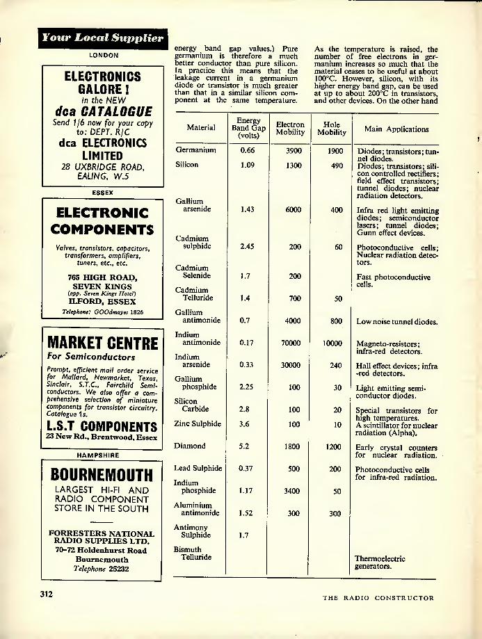
Four Local Supplier
LONDON
ELECTRONICS GALORE! in the NEW
dca CATALOGUE Send 1/6 now for your copy
to: DEPT. R/C dca ELECTRONICS
LIMITED 28 UXBRIDGE ROAD,
EAUNG, W.5
ESSEX
ELECTRONIC
COMPONENTS
Valves, transistors, capacitors, transformers, amplifiers,
tuners, etc., etc.
765 HIGH ROAD, SEVEN KINGS
(opp. Seven Kings Hotel) ILFORD, ESSEX
Telephone: GOOdmayes 1826
MARKET CENTRE For Semiconductors Prompt, efficient mail order service for Mullard, Newmarket, Texas, Sinclair, S.T.C., Fairchild Semi- conductors. We also offer a com- prehensive selection of miniature components for transistor circuitry. Catalogue 1s.
L.S.T COMPONENTS 23 New Rd., Brentwood, Essex
HAMPSHIRE
BOURNEMOUTH LARGEST HI-FI AND RADIO COMPONENT STORE IN THE SOUTH
FORRESTERS NATIONAL RADIO SUPPLIES LTD. 70-72 Holdenhurst Road
Bournemouth Telephone 25232
energy band gap values.) Pure germanium is therefore a much better conductor than pure silicon. In practice this means that the leakage current in a germanium diode or transistor is much greater than that in a similar silicon com- ponent at the same temperature.
As the temperature is raised, the number of free electrons in ger- manium increases so much that the material ceases to be useful at about 100oC. However, silicon, with its higher energy band gap, can be used at up to about 200oC in transistors, and other devices. On the other hand
Material Energy
Band Gap (volts)
Electron Mobility
Hole Mobility Main Applications
Germanium 0.66 3900 1900 Diodes; transistors; tun- Silicon
nel diodes. 1.09 1300 490 Diodes; transistors; sili-
con controlled rectifiers; field effect transistors; tunnel diodes; nuclear
Gallium radiation detectors.
arsenide 1.43 6000 400 Infra red light emitting diodes; semiconductor lasers; tunnel diodes;
Cadmium Gunn effect devices.
sulphide 2.45 200 60 Photoconductive cells; Nuclear radiation detec- tors.
Cadmium Selenide 1.7 200 Fast photoconductive
cells. Cadmium
Telluride 1.4 700 50
Gallium antimonide 0.7 4000 800 Low noise tunnel diodes.
Indium antimonide 0.17 70000 10000 Magneto-resistors;
Indium infra-red detectors.
arsenide 0.33 30000 240 Hall effect devices; infra -red detectors.
Gallium phosphide 2.25 100 30 Light emitting semi-
Silicon conductor diodes.
Carbide 2.8 100 20 Special transistors for
Zinc Sulphide 3.6 high temperatures.
100 10 A scintillator for nuclear radiation (Alpha).
Diamond 5.2 1800 1200 Early crystal counters for nuclear radiation.
Lead Sulphide 0.37 500 200 Photoconductive cells Indium
for infra-red radiation.
phosphide 1.17 3400 50
Aluminium antimonide 1.52 300 300
Antimony Sulphide 1.7
Bismuth Telluride Thermoelectric
generators.
312 THE RADIO CONSTRUCTOR
germanium is the more useful for work at low temperatures.
The energy band gap is not the only important property of a semi- conductor material. Two other prop- erties are shown in the Table, namely the electron mobility and the
hole mobility. These represent the ease with which electrons and holes move through the semiconductor material under an applied electric field. The lifetimes of the electrons and holes are also important. q
LANCASHIRE
Mastertape Box Clever
With the slogan "Box Clever", Mastertape (Magnetic) Limited recently launched a new kind of box for the three most popular sizes in their range of magnetic recording tapes.
Moulded in the form of a book from black high-strength polypropylene, the box has grained front and back covers with an elegant gold-lettered brand label on the front. The brand name is repeated on the spine in a colour which identifies the thickness of the tape inside (red for Standard-Play, yellow for Long-Play, etc.) and this is also printed, together with the reel size and tape length, on a spine label. Both the front cover and the spine are hinged, with snap-in fasteners to keep the box closed in storage.
Apart from the reel of tape in its polythene envelope, the box also contains a printed index card and a tape clip, and is sealed for despatch in plastic film.
The three sizes presented in the new box are the 5 in, 5| in and 7 in reels, in all thicknesses from Standard-Play to Triple-Play inclusive. Other reel sizes in the Mastertape range will continue in the present boxes for the time being.
With the introduction of the new box, Mastertape are also reorganising their distribution arrangements with the appointment of a number of regional wholesalers (list attached) from whom all supplies of branded Mastertape should be ordered.
/ANOTHER
CARTOON
H
U
C
K
L
£
"Look Dad, a semiconductor!'
HQ
BOS STOP
Please pay t>RlV£R. OhJ E.NTR.Y
P, o /
•_
CuTTy.
NEW CROSS
RADIO
Electronic components and Equipment,
Transistor Panels, all at competitive prices
6 Oldam Road, Newcross Manchester 4
Telephone CEN 1541
SURREY SMITHS PRECISION
t MINUTE DELAY ACTION SWITCH
Clockwork actuated 10/6 EACH 1 v/ w Post 2/6
(3 or more post free) Separate twitching up to 6 mint. Each action for loading up to IS amps. 250 volts. For photographic timer, sequence switching opera- tions, etc., etc. Brand new units at a fraction of their value. Connection sheet supplied.
Radio Component Specialists 337, WHITEHORSE ROAD,
WEST CROYDON, SURREY Phone 01-684-1665 FULL LIST 1/-
SUSSEX
E. JEFFERIES
For your new television set, tape recorder, transistor radio,
and hi-fi equipment. PHILIPS, ULTRA, INVICTA, DANSETTE.
MASTBRADIO, PERDIO, MARCONI. PHILCO, FIDELITY.
6A Albert Parade, Victoria Drive,
EASTBOURNE SUSSEX
An j
annual subscription
to
The
Radio Constructor
is the ideal gift
for Christmas
For details see foot of page 320
DECEMBER 1967 313

STOP READING
start building
start SW listening
For only £28.6.23. you can tiulld this exciting, instructive Short Wave Receiver. The Star Roamer kit looks and sounds professional—a beautifully finished charcoal grey cabinet and matching front with ham type operating fea- tures and performance. The perfect introduction to radio construction and ham techniaues — the perfect gift for enthusiast and novice alike. Like all Knightkits the Star Roamer is available fromElectronlques on convenient credit terms. It Is fully guaranteed and for any construction problem our friendly Service Department Is ready to advise and assist. Send for the FREE Knightklt 64-page brochure. It gives full details and performance specifica- tion on the Star Roamer and dozens of other unusual electronic kits. No real enthusiast can afford to be without a copy.
y - $ "'0 f 0
ta-—
I9 Please send me your FREE brochure K33 giving full details on the Knightklt ■ range. ■ Send to BLECTRONIQUES
| (Prop. STC) Limited, Edin- burgh Way. Harlow, Essex.
ADDRESS
_ uLtig-ix aj , -t-Lcui- AW *» i -uoow-o..
knight-kit
y Quality built in, built up by you electroniques
FREE
TO AMBITIOUS ENGINEERS —THE LATEST EDITION OF ENGINEERING OPPORTUNITIES
Have you sent for your copy? ENGINEERING OPPORTUNITIES is a highly informative 132-page guide to the best paid engineering posts. It tells you how you can quickly prepare at home for a recognised engineering qualification and outlines a wonderful range of modern Home Study Courses in all branches of Engineering. This unique book also gives full details of the Practical Radio & Elec- tronic Courses, administered by our Specialist Electronics Training Division—explains the benefits of our Appointments Dept. and shows you how to qualify for five years promotion in one year.
SATISFACTION OR REFUND OF FEE Whatever your age or experience you cannot afford to miss reading this famous book. If you are earning less than £30 a week send for your copy of "ENGINEERING OP- PORTUNITIES" today—FREE.
WHICH IS YOUR PET SUBJECT
Radio Television Electronics Electrical Mechanical Civil Production Automobile Aeronautical Plastics Building Draughtmanship B.Sc. City & Guilds General Certificate
of Education Etc., Etc.
BRITISH INSTITUTE OF ENGINEERING TECHNOLOGY
(Dept. 409B), Aldermaston Court, Aldermaston, Berkshire
PRACTICAL EQUIPMENT Basic Practice and Theoretical Courses for beginners in Radio T.V. Electronics Etc. A.M.I.E.R.E. City & Guilds Radio Amateur's Exam. R.T.E.B. Certificate. P.M.G. Certificate. Practical Radio. Radio & Television Servicing Practical Electronics Electronics Engineering Automation
POST COUPON NOW Please send me your FREE 132-page "ENGINEERING OPPORTUNITIES" (Write if you prefer not to cut page)
INCLUDING TOOLS! The specialist Electronics Division of B.I.E.T. NO W offers you a real laboratory training at home with practical equipment. Ask for details.
w
NAME ADDRESS
SUBJECT OR EXAM ..QO THAT INTERESTS ME THE B.I.E.T. IS THE LEADING INSTITUTE OF ITS KIND IN THE WORLD
314 THE RADIO CONSTRUCTOR
NOW AVAILABLE FOR THE FIRST TIME IN GREAT BRITAIN
TWO NEW TRIO COMMUNICATIONS RECEIVERS
These receivers offer the enthusiast high quality and the latest design developments at a realistic price
MODEL JR-500SE This high performance receiver is made especially to cover the amateur bands and utilises a crystal controlled double heterodyne circuit for extra sensitivity and stability Brief spec.: Covers all the amateur bands in 7 separate ranges between 3.5 and 29.7 Mc/s. Circuit uses 7 valves, 2 transistors and 5 diodes plus 8 crystals; output 8 and 500 ohm and 500 ohm phone jack. Special features: Crystal controlled oscillator # Variable BFO • VFO # AVC # ANL # S meter • SSB-CW # Stand-by switch # Special double gear dial drive with direct reading down to 1 kc/s # Remote control socket for connection to a transmitter. Audio output 1 watt. For use on 115/250 V A.C. Mains. Superb modern styling and control layout—finished in dark grey. Cabinet size 7 x 13 x 10in. Weight 18 lbs. Fully guaranteed, comp. with instruction manual and service data. LASKY'S PRICE 59 Gns. Carriage and Packing 12/6.
MODEL 9R-59DE Brief spec.: 4 band receiver covering 500 kc/s to 30 Mc/s continuous and electrical band spread on 10, 15, 20, 40 and 80 metres. 8 valve plus 7 diode circuit. 4/8 ohm output and phone jack. Special features: SSB-CW # ANL # Variable BFO 9 S meter 0 Sep. band spread dial # IF frequency 455 kc/s # Audio output 1.5 W # Variable RF and AF gain controls. For use on 115/250 V A.C. Mains. Beautifully designed control layout finished in light grey with dark grey case, size: 7 x 15 x 10in. Weight 19 lbs. Fully guaranteed, comp. with instruction manual and service data. LASKY'S PRICE 35 GnS. Carriage and Packing 12/6.
Z1
207 EDGWARE ROAD, LONDON, W.2 Tel. 01-723 3271 I 152/3 FLEET STREET, LONDON, E.C.4 33 TOTTENHAM CT. RD., LONDON, W.I Tel. 01-636 2605 The above branches open all day Saturday. Early closing Thursday. | Open all day Thursday. Early closing Saturday.
Mail Orders and correspondence to 3-15 Cavell Street, Tower Hamlets, London, E.I. Tel. 01-790 4821/2
Tel. FLE 2833
FOR RELIABLE COMPONENTS & RAPID MAIL SERVICE
2N3819 FET 15/-
BC107/8 5/-
2N2646 UJT 12/-
TD716 Tunnel diode incl. data sheet 12/-
0CP71 equiv. 9/6
0RP12 9/6
NEW!! THE
S-DEC 'BREADBOARD" FOR THE
ELECTRONIC AGE LASTS INDEFINITELY RE-USE COMPONENTS
AGAIN AND AGAIN IN STOCK AT L.S.T. 29/6 each
incl. free circuit book and free kit of accessories
'X" Line MODULES
Ready built solid state circuits X—161 2 Watt Amplifier 35/- X—191 Guitar Amplifier 35/- X—141 Record Player Amp. 35/- X—151 Intercom. 35/- X—481 Audio Booster 30/- X—461 Siren 35/- X—471 Burglar Alarm 35/- X—661 Metronome 30/- X—761 Morse Oscillator 20/- X—671 Lamp Flasher 32/6 X—691 Lamp Flasher (Double) 30/- X—261 Mic. FM Transmitter 35/- X—271 Telephone Transmitter 35/- X—241 R/Player Transmitter 35/- X—291 Guitar Transmitter 35/- X—371 Wireless Sentry 35/- These modules are not moulded in plastic and can be opened for servicing etc. S.A.E. for details.
We do not offer for sale semi- conductors of the "Re-marked" type, (for example our listing of Mullard transistors all bear the Mullard brand name) Furthermore all goods offered are subject to our normal money-back guarantee.
AC 126 6/- OA200 41- OCI40 9/6 AC 128 4/- OA202 4/- OCI70 4/- AC 176 6/- OC20 22/6* OCI7I 6/- ADTI40 11/6* OC22 13/-* OC200 6/-* AFI 14 4/9* OC23 25/-* OC202 13/-* AFI 15 4/9* OC25 9/6* 12/-* OC203 8/6* AFI 16 4/9* OC26 OC204 II/-* AFI 17 4/9* OC28 15/- OC205 10/6 AFI 18 9/- OC29 15/-* OCP7I 19/6 AFI 39 12/- OC35 12/- ORPI2 9/6 ACYI7 5/-* OC36 14/-* 2G38I 5/- ACY20 3/6* OC4I 3/6 2N385A 15/- ACY2I 4/-* OC42 4/- 2N696 7/-* AD 149 10/-* OC44 V- 2N706 4/- BAY3I 4/_* OC45 31- 2NI302 5/- BAY38 6/-* OC7I 3/6 2NI303 51- BCI08 5/- OC72 4/6 2NI304 6/- BCI07 51- OC73 3/3 2NI305 6/- BCI09 61- OC75 5I-* 2NI306 81- BCY40 16/- OC76 4/- 2NI307 8/- BCY3I 13/6* OC8I 31- 2N2I47 17/- BCZI 1 10/- OC8ID 31- 2N2I60 14/9 BFY50 6/-* OC8IZ 91- 2 N 2926 3/9 BFY5I 6/-* OC82 4/6 R53 23/- BFY52 6/-* OC82D 4/6 ST 140 3/-* BSY95A 4/9* OC83 41- STI4I 5I-* BY 100 si- OC84 6/- V405A 13/- OAS ne* OCI39 12/- XAI02 3I-* OA 10 OA70 2/6* 1/6 Items starred-* are price reductions OA79 OA8I 1/6 1/6 2/-*
Mullard output set 2 x OC8I + OA85 OC8ID 71- OA90 31- Mullard RF set 2 x OX45 + OA9I OC44 8/6
TRADE SUPPLIED-EXPORT ENQUIRIES WELCOME P. & P. PLEASE ADD 9d.
QUOTATIONS BY RETURN FOR QUANTITY 24 hour Postal Service
TELEPHONE 7904
SUPER SAVE PACKS
1 Pair 2N 1304/5 NPN/PNP 10/- 3 BCI09 High gain NPN 15/- 3 2N2926 Planar any gain 10/- 4 BCII3 Fairchild planar 10/- 10 DI476 (OC7I equiv) New 10/- 20 Mixed New transistors Germanium & Silicon Marked 20/— 20 Mixed New Diodes Germanium & Silicon Marked IS/— 16 Red & White spot New (8 red—8 white RF) 10/— 4 OCI6 equiv. (V30/30P) 10/- 2 OCI9 Mullard New io/- 2 2S722 Texas I00W Silicon 15/- 4 BYI00 Brimar 800piv 750mA I 3/— 4 OA2IO Mullard 400piv 550mA 12/- 12 OA200 equivalent (ISI30) 6/- 12 OA202 equivalent (ISI 32) 9/- 4 SLI03K lOOpiv I OA Stud Rects 15/— 4 SJI03E lOOpiv 2A Stud Rects 10/- 2 SCR's one at 400v 3Amp one at 50v I Amp (Seconds for turn-on time OK 50c/s) 10/- 2 l2volt I Watt Zeners I N202 10/- 36 Square inches Verboard .15" 10/- 2 I200volt I.SAmp Avalanche Rect 5Amp surge by S.T.C. 12/- 150 Assorted ceramic capacitors mainly colour coded ex- ceptional value—guaranteed satisfaction 10/— ALL PACKS ARE POST FREE! ! !
LSI COMPONENTS 23 New Rd. Brentwood. Essex.
DECEMBER 1967 315
THE MODERN BOOK CO
Basic Television Part 1. Pub: Tech. P. 21s. Postage 1s. Transistor Transmitters for the Amateur. By D. L. Stoner. 21s. Postage 1s. Troubleshooting with the Oscilloscope. By R. G. Middleton. 20s. Postage Is. Practical Oscilloscope Handbook. By R. P. Turner. 25s. Postage Is. Elementary Telecommunication Principles. By R. N. Renton. 30s. Postage 2s. Foundations of Wireless. By M. G. Scroggie. 21s. Postage Is. RSGB Amateur Radio Call Book. 1968 ed. 6s. Postage 9d. Service Valve & Semiconductor Equivalents. R.S.G.B. Pub. 5s. Postage 6d. A.R.R.L. Antenna Book. 18s. Postage 2s. Beginner's Guide to Radio Control. By R. H. Warring. 18s. 6d. Postage 1s.
Electronic Counting. A Mullard Pub. 27s. 6d. Postage Is.
Electronics Made Simple. By H. Jacobowitz. 15s. Postage 1s.
GEC Inter: Transistor Manual. 7th ed. 18s. Postage 2s.
Short Wave Listening. By J. Vastenhoud. 12s. 6d. Postage 1s.
Radio Circuits: A Step by Step Survey. By W. E. Miller revsd. by E. A. W. Spreadbury. 35s. Postage 1s.
Radio Servicing Vol. 4. Fault Finding. By G. N. Patchett. 8s. 6d. Postage 6d.
Worked Examples in Electronics & Tele- communications Vol. 1. By B. Holdsworth & Z. E. Jaeorski. 25s. Postage 1s.
Radio Valve Data. Compiled by "WW" 8th ed. 9s. 6d. Postage 1s.
We have the Finest Selection of English and American Radio Books in the Country
19-21 PRAED STREET (Dept RC) LONDON W2
Telephone PADdington 4185
UNDERSTANDING TELEVISION
by
J. R. DAVIES
UNDERSTANDING TELEVISION deals with: • Principles of 405 line reception • Principles of 625 line reception • Nature of the television signal • Receiver tuner units • A.F. and video amplifiers • Deflector coil assemblies • Automatic gain and contrast control • Receiver aerials • The cathode ray tube • Receiver i.f. amplifiers • Vertical and horizontal timebases • Synchronising • Power supply circuits • Colour television • COLOUR TELEVISION — 80 page
section deals comprehensively with this subject
Over 500 pages 300 diagrams 37/6
POSTAGE 2/6
The reader is required to haveonly a basic knowledge of elementary radio principles. The treatment is non- mathematical throughout, and there is no necessity for any previous experience in television whatsoever. At the same time, UNDERSTANDING TELEVISION is of equal value to the established engineer because of the very extensive range it covers and the factual information it provides.
To Data Publications Ltd., 57 Maida Vale, London, W9 Please supply UNDERSTANDING TELEVISION, Data Book No. 17
I enclose cheque/crossed postal order for
NAME
ADDRESS
BLOCK LETTERS PLEASE
316 THE RADIO CONSTRUCTOR

-V
SMALL ADVERTISEMENTS Rate: 9d. per word. Minimum charge 12/-.
Box No. 2/- extra.
Advertisements must be prepaid and all copy must be received by the 4th of the month for insertion in the following month's issue. The Publishers cannot be held liable in any way for printing errors or omissions, nor can they accept responsibility for the bona fides of advertisers. (Replies to Box numbers should be addressed to: Box No.—, The Radio Constructor, 57 Maida Vale, London, W.9.)
SERVICE SHEETS, 1925-1967. From Is. Catalogue 6,000 models, 2s. 6d. S.A.E. enquiries.—Hamilton Radio, 54 London Road, Bexhill, Sussex.
100 PAGE ILLUSTRATED CATALOGUE NO. 17 of Government and manufacturers' electronic and mechanical surplus, also a complete new section of the latest semi-conductors and miniature components, includes a credit voucher for 2s. 6d. Send for your copy now. Price 3s. post free. Arthur Sallis (Radio Control) Ltd., 93 North Road, Brighton, Sussex.
FOR SALE. Oscilloscopes—Galvanometers—Evershed & Vignolles Meggers—Relays—Uniselector Switches —Solenoids. Also other items and components. Free list. Stamp please.—R. & E. Mart, Box 9 G.P.O., Tunbridge Wells, Kent.
TORIOD COILS for sale. Suitable RTTY, etc. Mostly 88mH but some values above and below. S.A.E. for details. 7s. 6d. each. Box No. F289.
WIRELESS-MICROPHONE TRANSMITTERS. From 25s. each. Send s.a.e. for details. Also 1 x 1 x lin trans- mitters (including built-in microphone) available in kit form or ready made.—Mr. Bobker, 64 Choir Street, Salford 7, Lanes.
EQUIPMENT MANUFACTURERS SURPLUS STOCK GUARANTEED NEW IN PERFECT CONDITION. Transformers: Prim. 0-220-240 Sec. 1 16-0-16 600mA, Sec.2 16-0-16 25mA, ideal for stabilisers 25s. Photocells ORPI2 5s. Transistors: 2N1305 2s. 6d. ACY18 2s. Diodes: OA91 and equiva- lent 7d. Zeners: I2V 7w 8s., 12V 1.5w 4s. Relays: Keyswitch MM2 12V d.c. 100mA coil 2CO 15A a.c. 19s. 6d. Skeleton pots: 25k, 5000 6d. Metal Boxes with lids, 6x6 x 3in. sprayed grey 12s. P.C. boards for all layouts, published in Radio Constructor are always available. Minimum order £1. HELGA ELECTRON- ICS LTD., Eaglescliffe, Stockton-on-Tees, Co. Dur- ham. Telephone Eaglescliffe 3644.
5 TON FACTORY CLEARANCE. Radio, TV, elec. components in 15s. and 27s. 6d. mixed parcels. Post free. Example: resistors, condensers, pots., speakers, coax, coils, fibre washers, valves, over a dozen different types, tuning knobs, grommets, sleeving, IFS, Paxalin, wire, rectifiers. Lots of other items. Pot luck. Postal orders to: P. L. Newton, 10 Cecil Road, Muswell Hill, London N.10.
BRIGHTEN UP YOUR ADVERTISING! Break the ice with a cartoon, "tailor made" for your product. Reasonable charges. Box No. F294.
BOOKS FOR SALE. Hi-Fi Projects for the Hobbyist, Fieldman, 10s. Electronic Valves in A.F. Amplifiers, Rodenhuis, 3s. 6d. Tubes for Computers, Philips, 5s. 6d. Industrial Rectifying Tubes, Philips, 5s. 6d. U.H.F. Tubes for Communication and Measuring Equip- ment 5s. 6d. Instructions to Radio Constructors, Warring, 7s. 6d. All post free. Box No. F297.
continued on page 318
BENILEY ACOUSTIC CORPORATION LTD. 38 Chalcot Road, Chalk Farm, 47 Norfolk Road, LONDON, N.W.I. LITTLEHAMPTON, Sussex PRImrose 9090 Littlehampton 2043
Please forward all mail orders to Littlehampton 5Z4 7/6 ECF80 71- PC95 6/9 UBF80 5/6 AFI 27 3/6 GET898 4/6 6AT6 3/9 ECF82 6/9 PC97 5/9 UBF89 5/9 AFI 39 M/- OAS 1 1/9 6/30L2 12/6 ECF86 8/6 PC900 8/6 UC92 5/6 AFI 80 9/6 OA95 1/9 20DI 13/- ECH42 8/9 PCC84 5/6 UCC84 81- AFI86 10/- OA 182 21- 20P4 17/6 ECH8I 51- PCC85 6/9 UCC85 6/6 AFZI2 51- OA200 21- 30CI5 12/- ECH83 71- PCC88 10/6 UCF80 8/3 BAI 15 2/8 OCI9 251- 30CI7 13/- ECH84 6/6 PCC89 9/9 UCH2I 91- BAI79 2/6 OC22 51- 30CI8 9/6 ECL80 61- PCCI89 8/3 UCH42 8/6 BA 1 . j 2/- OC23 71- 30F5 11/6 ECL82 6/3 PCF80 6/3 UCH8I 61- BCI07 41- OC25 51- 30FLI 15/- ECL83 91- PCF82 61- UCL82 71- BCI08 3/9 OC26 51- 30FLI2 15/- ECL86 7/9 PCF84 8/- UCL83 8/9 BCI09 4/6 OC28 51- 30FLI4 12/6 EF4I 91- PCF86 8/- UF4I 7/9 BCYI0 5/- OC30 71- 30LI5 14/- EF80 4/6 PCF80I 8/6 UF42 4/9 BCYI2 51- OC35 10/- 30LI7 13/- EF85 4/6 PCF802 9/6 UF80 6/9 BCY33 51- OC36 7/6 30P4 11/6 EF86 6/3 PCL82 6/3 UF85 7/3 BCY34 51- OC38 1 116 30P4MR 13/- EF89 4/9 PCL83 8/6 UF86 91- BCY38 51- OC4I 10/- 30PI2 M/- EFI83 6/3 PCL84 71- UF89 5/6 BCY39 51- OC44 21- 30PI9 M/- EFI84 5/9 PCL85 8/3 UL4I 8/9 BFY50 51- OC45 1/9 30PLI 15/- EH 90 7/6 PCL86 81- UL84 5/6 BFY5I 4/6 OC46 21- 30PLI3 15/- EL33 12/- PFL200 13/6 UM80 51- BFY52 51- OC70 212 30PLI4 15/- EL4I 8/- PL36 91- UY4I 5/6 BFI63 41- OC7I 21- DM70 61- EL42 7/6 PL8I 6/9 UY85 4/9 BY 100 3/6 OC72 21- DY87 5/9 EL84 4/6 PL82 5/9 2N404 61- BY234 41- OC75 21- E88CC 12/- EL95 51- PL83 61- AC 107 3/6 BY236 41- OC76 21- EABC80 5/9 ELL80 13/- PL84 6/3 ACI 13 51- BY238 41- OC77 3/4 EAF42 7/6 EM 80 5/9 PL500 13/6 AC 126 21- BYZI2 51- OC78 21- EB9I 2/3 EM8I 6/9 PY8I 51- AC 127 21- BYZI3 51- OC78D 21- EBC4I 7/3 EM84 61- PY82 51- AC 128 21- GET 103 41- OC8I 21- EBC8I 6/3 EM 85 II/- PY83 5/6 AC 154 51- GETI 13 41- OC8ID 21- EBF80 5/9 EM 87 6/6 PY88 7/3 AC 157 51- GETI 16 7/6 OC82 212 EBF83 71- EY5I 5/6 PY800 61- AC 156 41- GETI 18 4/6 OC83 21- EBF89 5/9 EY86 5/9 PY80I 61- AD 140 81- GETI 19 4/6 OC84 21- EC92 6/6 EY88 7/6 U25 12/6 AD 149 81- GET573 8/6 OCI23 4/6 ECC8I 3/6 EZ40 61- U26 II/- AFI 14 41- GET587 8/6 OCI69 3/9 ECC82 4/6 EZ4I 6/6 U 191 12/- AFI 15 21- GET873 41- OCI70 2/6 ECC83 4/6 EZ80 3/9 U30I 12/6 AFI 16 21- GET887 4/6 OCI7I 3/4 ECC84 5/6 EZ8I 4/3 UABC80 5/3 AFI 17 3/4 GET889 4/6 OC172 41- ECC85 51- KT66 16/6 UAF42 7/9 AFI 18 21- GET890 4/6 OC200 6/6 ECC88 71- PC86 8/6 UBC4I 6/6 AFI 19 21- GET896 4/6 OC202 5/6 ECCI89 91- PC88 8/6 UBC8I 6/6 AFI 25 3/6 GET897 4/6 OC203 5/6 Terms of business: Cash with order only. No C.O.D. Post/Packing 6d. per item. Orders over £5 post free. All orders despatched same day as received Complete catalogue including transistor section and components with terms of business 6d. Any parcel insured against damage in transit for 6d. extra. We are open for personal shoppers 9 a.m.-5.30 p.m. Saturdays 9 a.m.-I p.m.
SAVE WITH SILICON Do you know that by exploiting modern high-gain planar transistors you can halve the number of resistors and capacitors in a circuit? And silicon planars are now cheaper than inferior germanium types. As an object- lesson, consider our new 9V TRF DESIGN. This is a brilliant development of the AMATRONIX SIMPLE TRF for 3V working, using the latest low noise high gain epoxy-encapsulated planars. The two r.f. stages and high- gain transistor detector use only nine fixed resistors and six fixed capacitors. To this you can add a choice of a.f. stages: a single Class A stage provides low-volume speaker listening, or blast-your-ears-off headphone reception, and by adding a complementary Class B pair to this you can get enough power for high-volume speaker reception. With our detailed circuit description and price list we provide money- saving hints on how to use your old ferrite rods, headphones, tuning capacitors, and loudspeakers. Send only 6d. and get some food for thought for your Christmas holidays.
TRANSISTORS NOT "seconds", NOT "equivalents", NOT unheard-of types of unknown parentage, but NEW, FIRST GRADE, and GUARANTEED goods. DIS- COUNT PRICES (in brackets) for 5 OR MORE OF SAME TYPE. List, with data and useful circuits, 3d: free with all orders. BCI07 (hfe=250-500) 4/- (3/9); BC109 4/- (3/9); BCI68 (epoxy BCI08, hfe=250-500) 3/- (2/6); B-5000 (25W n.p.n. silicon) 10/- (9/-); HKIOI (r.f./i.f. amp.), hfe = 30-60, 2/- (1/9), 50-100, 2/3 (2/-), 90-180, 2/6 (2/3), 150-450, 31- (2/6); H K301 (v.h.f. amp.) hfe=20-60, 2/- (1/9), then as HK101 HK04I (p.n.p. medium power) from 2/6 (2/3); HK60I, hfe 20-300, 2/6 (2/3), 300-600. 3/6 (3/-); 2N706. 3/6 (3/-); 2N2926 (all colours) 3/- (2/6); 2N3702, 4/- (3/6); 2N3703. 4/- (3/6); 2N3704, 4/- (3/8); 2N3705. 4/- (3/6); 2N3707, 51- (4/6); 2N3983. 6/- (5/6); 2N4058, 5/6 (5/-).
Mail order only. Cash with order. U.K. post free on orders over 10/- (otherwise add 6d). Discounts: 10% over £5. 15% over £10. Special quota- tions for large quantities.
AMATRONIX LTD. (DEPT. RC 12) 396 SELSDON ROAD. CROYDON, SURREY, CR2 ODE
DECEMBER 1967 317

NEW STYLE
SELF-BINDER
for "The Radio Constructor »>
The "CORDEX" Patent Self-Binding Case will keep your issues in mint condition. Copies can be inserted or removed with the greatest of ease. Rich maroon finish, gold lettering on spine. Specially constructed Binding Cords are made from Super Linen of great strength, very hard twisted and twice doubled. They
are attached to strong RUSTLESS Springs under tension, and the method adopted ensures PERMANENT RESILIENCE of the Cords. Any slack that may develop is immediately compensated for, and the Cords will always remain taut and strong. It is impossible to overstretch the springs, as a safety check-device is fitted to each.
SMALL ADVERTISEMENTS continued from page 317
?■.
' !
v
V;
PRICE 15f ■ Post Free
PLAIN BACKED 14/6 Post Free
Available only from;—
Data Publications Ltd.
57 Maida Vale London W9
YOUR KITS EXPERTLY BUILT, repaired, modified. Mains or battery equipment. For estimate write, enclosing s.a.e. please, to; W. Thomas, 6 North Avenue, Ruabon, Nr. Wrexham, Denbighs.
FOR SALE. Geloso G109 amateur-bands communica- tions receiver, 14-tubes. Excellent condition and performance. £25 o.n.o.—Tyler, Tudor Farm, Little- wick, Berkshire.
BARGAIN PARCELS! 120 (minimum) radio parts, etc., mostly new, 12s. 6d. a parcel. G. Hart, Lings Lane, Chelmondiston, Ipswich, Suffolk.
TECHNICAL DRAWINGS, Artwork, etc. Electronic and Radio Circuits a speciality. Moderate charges. —B. P. Meaney, 43 Forest Road, Worthing, Sussex.
LIMITED QUANTITY PCF80, PCC84, EF80, EBF80, ECL80, 6V6, 6Q7, 6K7. All 5s. Tested. C.W.O. Webberley, 19 Baring Road, New Barnet, Herts.
"MEDIUM WAVE NEWS" Monthly during DX season—Details from: K. Brownless, 7, The Avenue, Clifton, York.
19 SET FOR SALE. New condition, with a metered mains power unit, £12.—Rolls, 23 Brandreth Avenue, Dunstable, Beds.
PRINTED CIRCUIT BOARDS MADE AND DRILLED Send full scale drawing and 5d. per square inch. Prompt service. Minimum charge 3s. S.A.E. enquiries. R. D. Crabtree, 213 Hyde Park Road, Leeds 6, Yorks.
MICROPHONES. Crystal, stick, with anodised keyhole stand, outside customers' limits but guaranteed working order, from known manufacturer, 10s. 6d. each, p. & p. paid.—Box No. F313.
MARCONI No. 9 RECEIVER. Complete with crystal calibrator, meter. 1.8 - 5.00 Mc/s Perfect. £5. Suitable power pack £3. Also CR100 receiver, requires atten- tion, £3.10.0d. Collection advised or carriage extra. —Phone 01-440-3569 after 6 p.m.
STOCK CLEARANCE: Correx mains transformers, varnish impregnated, termination board termination, Pri. 0/115/200/220/240 E/S, Sec. 48/50/52V 3A. Offered at a fraction of original cost to clear. Brand New, 29s. 6d. each, p. & p. 5s. 6d. Trade enquiries invited.—Davies, 12 Hampden Hill, Ware, Herts.
ARE YOU A MOTORING ENTHUSIAST ? The Seven Fifty Motor Club caters for all types of motor sport—racing, rallies, hill climbs, etc. Monthly Bulletin free to members. For full details write to: The General Secretary, Colin Peck, "Dancer's End," St. Winifred's Road, Biggin Hill, Kent.
JOIN THE INTERNATIONAL S.W. LEAGUE. Free Services to members including Q.S.L. Bureau. Amateur and Broadcast Translation. Technical and Identification Dept.—both Broadcast and Fixed Stations, DX Certificates, contests and activities for the SWL and transmitting members. Monthly maga- zine, Monitor, containing articles of general interest to Broadcast and Amateur SWLs, Transmitter Section and League affairs, etc. League supplies such as badges, headed notepaper and envelopes. QSL cards, etc., are available at reasonable cost. Send for League particulars. Membership including monthly magazine, etc., 35s. per annum.—Secretary, ISWL, 60 White Street, Derby.
continued on page 319
318 THE RADIO CONSTRUCTOR

SMALL ADVERTISEMENTS continued from page 318
BOOKS FOR SALE: "Alfred Nobel" E. Bergengren £1. "Black Sailed Traders" R. Clark, 7s. 6d. "Radioisotope Laboratory Techniques" R. A. Faires, 10s. "Optical Microscope Technique" D. Birchon, 10s. "Atomic Medicine" Behrens, £1. "Medical Radiation Biology" Ellinger, 30s. '''Effects of Atomic Weapons" U.S.A. Atomic Energy Commission, £1. "Physics in Medical Radiology" Russ, Clark & Pelc, 7s. 6d. "Disease & its Conquest" HoIIis 7s. 6d. "Earth's Envelope" T. Lobsack, 15s. "The Atomic Submarine" C. Blair, 7s. 6d. "Astronautics in the Sixties" K. W. Gatland, 30s. "Space Research and Exploration" D. R. Bates, £1. "Once Round the Sun" Story of the I.G.Y., Eraser, 10s. "Earth Satellite" P. Moore, 7s. 6d. "Frontier to Space" E. Burgess, 5s.—Box No. F316
THE WORLD'S SMALLEST BUG (Wireless micro- phone). Rifle bullet size. £7.10.0. Post free. Shirt button size microphone 12/6.—Box No. F317.
RECITALS OF RECORDED MUSIC. The second Saturday evening of each winter month. Next recital: 9th December, 1967, 8 p.m. Woodford Green United Free Church, Woodford Green, Essex. Bus routes 20, 20A, 38A and 179—alight at "The Castle" stop. Programme includes works by Bach, Marcello, Gabrieli, and Ravel.
PQSTAL ADVERTISING? This is the Holborn Service. Mailing lists, addressing, enclosing, wrappering, facsimile letters, automatic typing, copy service' campaign planning, design and artwork, printing and stationery. Please ask for price list.—The Holborn Direct Mail Company, 2 Mount Pleasant, London, W.C.I. Telephone: TERminus 0588.
DAMAGED DICTAPHONES with microphone and belts. No parts removed, still in original case. £4 each including carriage.—G. Simpkin, Box No. F318.
INNOVATION IN DX CLUBS ANNOUNCED! Formed in October, 1965, the Radio New York Worldwide Listeners Club now has 3,600 members in 86 countries! A unique club offering shortwave listeners monthly magazines containing listening tips and technical features, numbered wallet-sized membership cards and gold 8jin. by 11 in. membership certificates. Multi-lingual report forms available for cost of postage. "We must be doing something right!" Find out . . . join now! Send 7s. 2d. (crossed domestic money order) for one year's membership to ;-The Radio New York Worldwide Listeners Club, 485 Madison Avenue, New York 10022, U.S.A.
ESSEX GARDENERS. Buy your bedding and rock plants, shrubs, etc., also cacti, from May's Nurseries, 608 Rayleigh Road, Hutton, Brentwood, Essex. Callers only, Monday to Saturday.
PROPERTIES for sale and to let in London and suburbs. Apply to Maggs & Stephens, Estate Agents, 229 Maida Vale, London, W.9. MAIda Vale 8123.
QUALIFY as a technician, to service COMPUTERS, COLOUR TELEVISION, AUTOMATIC CONTROL SYSTEMS. Day or evening courses, includes extensive practical work, using modem equipment. Also special course (2 days per week) enabling beginners to reach City and Guilds Intermediate level in six months. Full details from: Section 47/48, Southall College of Technology, Beaconsfleld Road, SOUTHALL Middlesex.
&&&&&&&&&&&&&&&&&
ideal Xnias Gm
THE RADIO CONSTRUCTOR
SPECIAL PRIVILEGE PRICE OF
TDLTEC ^
HAIR DRYER
m
SPECIFICATION Moulded in beautiful symmetri- cal pastel blue impact resisting thermoplastic casing. Quiet in operation. Hot or cold air. No radio or T.V. Interference- meets British standard specifi- cation. Fitted with safety cut-out. 12 months &• money refund guarantee. 230-250 volts A.C. only. Value 80/9 in the shops Send the coupon below with the sum of only 57/- (this includes 4/6d to cover postage, packing and insurance, unless you are collecting personally).
Please send me one Toltec Hair Dryer at the special privilege price as advertised in The Radio Constructor
I enclose cheque/postal order value
Name
Address
(Block capitals please) To: Toltec Electronic & Trading Co. Ltd. Hatton House, Hurst Green, Etchingham, Sussex
DECEMBER 1967 319

CHASSIS and
CASES by
H. I. SMITH &C0. LTD. 287/9 Edgware Road
London W2 TEL: 01-723 5891
CASES ALUMINIUM, SILVER HAMMERED FINISH _
Type Size ~ " "" U 4 x 4 x 4"* U 5^x4^x4^" U 8x6x6" U 9ix7ix3i" U 15x9x9" W 8»x 6 x 6" W 12x7x7"
* Height Type Z has removable back and front panels. Type Y all-screwed construction.
Type W Price Type Size Price 10/- W 15 x 9 x 8" 44/- 15/6 Y 8x6x6" 26/6 11/- Y 12x7x7" 41/- 211- Y 13x7x9" 46/- 44/6 Y 15x9x7" 48/6 71/- Z 17x10x9" 66/- 34/- Z .19 x 10 x Si" 71/-
TypeY Type Z
Type U
immmm
BLANK CHASSIS—Same Day Service Of over 20 different forms made up to YOUR SIZE.
(Maximum length 35", depth 4".) SEND FOR ILLUSTRATED LEAFLETS or order straight away, working out total area of material re- quired (including waste) and referring to table below which is for four-sided chassis in 16 s.w.g. aluminium. 48sq. in. 4/6 176 sq. in. 9/10 304 sq. in. 15/2
208 sq. in. 11/2 240 sq. in. 12/6 272 sq. in. 13/10
P. & P. 3/6
336 sq. in. 16/6 368 sq. in. 17/10 and pro rata
P. & P. 4/6
80 sq. in. 5/10 112sq. in. 7/2 144sq. in. 8/6
P. & P. 3/- Discounts for quantities. More than 20 different
sizes kept in stock for callers. FLANGES (i" or §"). 6d. per bend. STRENGTHENED CORNERS, 1/- each corner.
PANELS Anv size up to 3ft at 6/- sq. ft. 16 s.w.g. (18 s.w.g. 5/3).
Plus postage and packing
* HAMMERITE HAMMER ENAMEL
AIR DRYING • JUST BRUSH ON ± pint 8/-, p.p. 1/9, I pint 16/-, p.p. 3/-. Blue, silver, black, bronze (and others). NO PRIMERS NEEDED. Just try it. Brushed sample, interesting list FREE. INDUSTRIALISTS ! ! ! SAVE TIME AND £££'s (2 pints will do a Mini) FINNIGAN SPECIALITY PAINTS (RC) Mickley Square. Stocksfield, Northumberland. Telephone: Stocksfield 2280
TRIAL TIN (covers 5 sq. ft.)
3/9 + 9d. post
SPECIALISTS IN JOINERY MADE CABINETS Made to your design to take stereo and wireless equipment. In beautiful wood veneer. Finish to match your own furniture. Example: 4" x 16" x 18", Teak finish, from £45. Send your enquiries to:
R. C. Whitby (Cabinets) 700 Foxhall Road, Ipswich, Suffolk.
-'obow
CE C M1492
WANTED This and similar scrap relays
BEST PRICES PAID S.a.e. to "Lanco", 76 Sedgemoor Rd., Wiilenhall, Coventry, Warwickshire
BULK COMPONENT BARGAINS
★ Qfifl ASSORTED RESISTORS—HI-STAB (5% i/io to 1/2 watt, worth £3)
S.A.E. FOR LIST OF INDUSTRIAL COMPONENTS FOR THE HOME CONSTRUCTOR
Elmbridge Instruments Ltd. w"tMo1«.^vsurr.y
PRINTED CIRCUIT BOARDS with two OC 35's on heat sinks and 6 other transistors plus diodes etc., per board Minimum of six M.A.T. Transistors on Printed Panel with Zeners, silicon diodes etc Airspaced Transistor Tuning Condensers 365 pF
100 + 100 pF with SM drive 208 + 176 pF with SM drive
Loudspeakers 2" 80 ohm 2^" 35 ohm Driver Transformer for above Loudspeakers Toggle Switches single pole
D.P.D.T I mA 2" square Moving Coil Meters Stud Mounting Rectifiers 200 P.I.V. 2 Amps
200 P.I.V. 6 Amps Wire-ended plastic encapsulated 400 P.I.V. 500 mA
800 P.I.V. 500 mA Power Transistor Holders Electrolytic Condensers I uF I2v.w, 2nF 12 v.w, 8uF 30 v.w, 50uF 12 v.w, IOOuF 12 v.w, all I/- each 9/- dozen Silicon General Purpose NPN Transistors (300 Mc/s) F.E.T. MPFI05 AFZI2 BCY34 BCY38 BCI50 BCZII BFY50 BFY5I BFY52 BFY53
8/6 4/6 4/- 4/- 5/6 7/6 4/6 4/6 4/6 4/6
AD 161/162 matched pairs 2N502 2N706 2N706A * 2N708 2NI305 2N2926 2N3663
18/6 14/- 4/6 5/- 7/6 5/6 2/9 II- 2/6
17/6 21- 2/6 I/- 2/6 I/-
2/6 12/6 8/6 3/6 4/6 5/6 3/- 3/6 8/6
Single M.A.T. Transistor on P.C. Board plus other components per panel 2/6
|. Birkelt, 25 The Strait, Lincoln TELEPHONE: 20767
THE RADIO CONSTRUCTOR
ANNUAL SUBSCRIPTIONS to this magazine
may be obtained direct from the publishers
ONLY 36/- per year, post free Please send remittance with name and address and commencing issue required to:
DATA PUBLICATIONS LTD 57 MAIDA VALE LONDON W9
Please mention THE RADIO CONSTRUCTOR when writing to advertisers
320 THE RADIO CONSTRUCTOR

THE RADIO CONSTRUCTOR
Price 2/6 each, postage 6d. Annual Subscription 36/-, post free. Bound Volumes Vol. 19 August 1965 to July 1966 32/6, postage 4/6.
Vol. 20 August 1966 to July 1967 32/6, postage 4/6. Cordex Self-Binders With title "The Radio Constructor" on spine, 15/-, post free.
With no title on spine 14/6, post free.
DATA BOOK SERIES
DBS TV FAULT FINDING 124 pages. Price 8/6, postage 8d.
DB6 THE RADIO AMATEUR OPERATOR'S HANDBOOK 64 pages. Price 5/-, postage 5d.
DB14 SHORT WAVE RECEIVERS FOR THE BEGINNER 72 pages. Price 6/-, postage 6d.
DB15 TWENTY SUGGESTED CIRCUITS 48 pages. Price 3/6, postage 5d.
DB16 RADIO CONTROL FOR MODELS 192 pages. Price 15/-, postage 9d.
DB17 UNDERSTANDING TELEVISION 512 pages. Price 37/6, postage 3/-
PANEL-SIGNS TRANSFERS
Six sheets in each set Set 3: WORDING—White
Set 4: WORDING—Black
Set 5: DIALS—Control Panels have no background
Set 6: DIALS—Control Panels have a black background
Price per set 4/6, postage 4d.
I enclose Postal Order/Cheque for in payment for
Name -
Address
(Please use Block Capitals for both name and address) Postal Orders should be crossed and made payable to Data Publications Ltd.
Overseas customers please pay by International Money Order All publications are obtainable from your local bookseller
Data Publications Ltd., 57 Maida Vale, London W.9

NEW SOLID STATE HIGH FIDELITY EQUIPMENJ (British made) 'ower Amplifiers-Pre Amplifiers-Power Su
•4MP3 SP6-2
RiO
m m MPA25 N M MPA 12/15
WE PROUDLY PRESENT THIS NEW RANGE OF AUDIO EQUIPMENT developed from DINSDALE Mk. II—each jnit or •yttem will compare favourably with other professional equip- ment selling at much higher prices. Brief details are below SYSTEM COMPRISING SYSTEM PRICE k. A 5 watt mono for £4t\ 1 ft 3/5 ohm speakers. ★1 12 watt mono for 3 to 5 ohm speakers. £13.17.6 ★ 2 12 watt mono for 12 to 16 ohm speakers. £14.12.6 ★ 4 24 watt mono two channel for 12 to 16 ohm speakers. £20.15.0 00 *
20 watt mono/stereo for 12 to 16 ohm speakers. £24.0.0 ★ 9 24 watt mono/stereo for 3 to 5 ohm speakers. £26.15.0 ■x. 14 40 watt mono/stereo ^ 1 • T\ to 16 ohm speakers. £29.10.0
Complete fully illustrated brochure free on request THE FINEST VALUE IN HIGH FIDELITY — CHOOSE A SYSTEM TO SUIT YOUR NEEDS AND SAVE POUNDS
SEND FOR FULL DETAILS ON ADVERTISED PRODUCTS. FREE ON REQUEST VHF FM TUNER
I
z
FM STEREO DECODER
BUILD A QUALITY TAPE RECORDER
87/105 Mc/s Transistor Superhet. Geared tuning. Terrific quality and sensitivity. For valve or transistor amplifiers. 4 x 3^ x 2i-in. Complete with dial plate. 5 MullardTransistors, Plus 4 Diodes. (Cabinet Assembly 20/- extra). TOTAL COST /A 19 A TO BUILD S.O. IT.O P.P. 2/6
7 Mullard Transistors. Printed Circuit Design with Stereo Indicator. For use with any valve or transistor FM. Uses pot cores to Mullard design and ger. and silicon transistors. As used by B.B.C. and G.P.O. COMPLETE rc 4 Q ^ KIT PRICE tD. IT.O P.P 2/w
3-speed version using *363' decks ★TWO-TRACK. Deck £10.10.0. Martin Amplifier. £14.19.6. Cabinet and speaker 7gns. Complete kits with FREE 7in. 1,200ft. tape, spare 27 gns. Kf.
★FOUR-TRACK. Deck £13.10.0. Martin Amplifier £15.19.6. Cabinet and speaker 7gns. Complete kits with FREE 7in. 1,200ft. tape, spare svp
afu0l'£T5°oday's 30 gns. I;?;
AUTO-BAN TRANSISTOR CAR RADIO British Made
MW/LW QUALITY TRANSISTOR RADIO TUNER Fully tunable superhet with excellent sensitivity and selec- tivity. Output up to i volt peak. Complete with front panel, etc. 9 volt operated. For use with any amplifier or tape recorder.
TOTAL COST /"> 4 Q A TO BUILD tJ.IT.O P.P. 2/6
I»
GLOBEMASTER
REGENT-6 MW/LW POCKET RADIO TO BUILD 6-Transistor superhet. Geared tuning. Push-pull speaker output. Moulded Cabinet 5 x 3 x liin. Phone socket. TOTAL TO BUILD P.P. 2/6 Full tuning on both bands. 6-Transistor MW/LW Car Radio 12 volt operated. 3 watt output. Push-button, wavechange. Supplied built, boxed, ready to use with Speaker and Baffle. Car fixing kit and manufacturers' current guaran- tee. Special Bargain Offer. Positive or Negative Earth. LIST PRICE 12 GNS. Push-button version aq 4 A £11.19.6. P.P. 4/6 10.17.0 4/6
7-TRANSISTOR MW/LW SUPERHET NEW! PORTABLE New printed circuit design with full power output. Fully tunable on both mw/lw bands. 7 Transistors plus diode, push-pull circuit. Fitted 5 inch speaker, large ferrite aerial and Mullard transistors. Easy to build with terrific results. All local, and continental stations. TOTAL COST TO BUILD r £6.19.6 6-Mullard Transistors 7x4 speaker very sensitive excellent coverage Full 3-waveband tuning. Pushbutton wavechange. Superhet printed cir- cuit. Black-chromed cabinet I I x 7^ x 3iin. (SW 17-50 metres). Ear/ Record sockets. I watt push-pull. Now with new De Luxe Cabinet.
TOTAL /A lO A P-P* COST tO.lV-O 4/6
MAYFAIR H PORTABLE ORGAN
ELECTRONIC tfw3 ROCHE We regret to nounce the i timely passing of Mr. LEWIS R. ROCHE on Oct. 14th last—He will be sadly missed by his many friends and colleagues.
Build this instrument stage by stage in your own home. A truly portable instrument for all enthusiasts. Fully TRANSISTORISED POLY- PHONIC, British design. Call in for a DEMONSTRATION.
TOTAL COST
99 GNS
ORGAN COMPONENTS We carry a compre- hensive stock of organ components for TRANSISTOR AND VALVE FREE PHASE designs.
CATALOGUE
The most COMPREHENSIVE — CONCISE — CLEAR — COMPONENTS CATALOGUE. Complete with 10/- worth discount vouchers FREE WITH EVERY COPY. ★20 pages of transistors and semi-conductor devices, valves and crystals. ★ 150 pages of components and equipment. ★50 pages of microphones, decks and Hi-Fi equipment.
LATEST EDITION
225 pages, 6000 items 1000 illustrations
SEND TODAY 8/6 POST PAID
ii
QJ
HENRY S RADIO Telephone (01) 723-1008/9 OPEN M0N.-SAT. 9 a.m.-6 p.m. THURS. 9 a.m.-l p.m.
303 EDGWARE ROAD LONDON W2
Transistors & Semi-Conductor Devices We have the LARGEST RANGE OVER 650 TYPES ★ COMPETITIVE PRICES ★FULLY G UARANTEED ★ 1st GRADE STOCKS. SEND FOR FREE LIST No. 35 Also 24-PAGE ILLUSTRATED BROCHURE LIST- ING 2000 DEVICES with data and circuits, including VALVES and QUARTZ CRYSTALS I/- Post paid