the zero g eye - news & updates — mit media...
TRANSCRIPT

The Zero G Eye: Towards A Free Hovering Camera Page 1 of 12
The Zero G Eye: Towards A Free Hovering Camera
Stefan Marti, January 24th, 2000
Technical Report of final project of
MAS.863 How to Make (Almost) Anything
Original Idea
I would like to have additional visual perspectives of my environment. Normally, I am restricted through the position of my eyes in about what I actually see. If I would have an additional third eye that is not physically connected to my body, I would have the possibility to look at myself from above or from a perspective in front of me.
How I planned to realize it
One or several small flying devices, very quiet and unobtrusive, less than 10 cm in diameter, which just hover constantly above me and follow me. They are speech controlled, so that I can tell them “Go higher,” “Turn left” etc. They have small video cameras mounted on them and transmit this signal to my watch that has a built in LCD screen. The watch holds also a microphone. The speech is evaluated in the watch and the navigation signals are sent to the Zero G Eye.
How far I got
Since this idea was obviously too big for a class project, I limited my ambitions a bit: I intend to create a Free-Flying Platform that is hovering autonomously. It's not a “real” Zero G Eye yet, because of the following things: • It hasn’t flown yet. It is just not secure enough! First I have to build some kind of
scaffold to hold it, or some kind of elastic rope suspension. • No camera yet. Putting a wireless micro camera on it is actually not a hard part; it is
just a question of payload and lift. My current prototype platform could indeed lift the lightest available wireless video camera.
• Not speech controlled yet. Currently, the PC just tries to keep the vessel at its hovering position. However, extending the software and linking voice recognition code to control the movement of the platform on a higher level, e.g., “Go left,” would not be very hard.

The Zero G Eye: Towards A Free Hovering Camera Page 2 of 12
• Limited range. Although the transmitter and receiver have a range of up to a mile, the current prototype uses a commercially available ultrasonic sensor which limits its range to an area of about 1x1x1.5 meters. This is good enough for automatic hovering tests.
• Limited flight time. The batteries last only about 2 minutes. More about batteries: see below.
Note: The Zero G Eye is a prototype of an FFMP, a Free Flying Micro Platform.
Design studies
First I tried to determine the most appropriate design.
Four ducted fans wrapped in donuts. This idea is obviously UFO inspired. Two of the four electric impellers will run clock-wise, two of them counter-clockwise. Like that, the helicopter can be controlled by a combination of speed changes of the four rotors. (Both the Keyence Gyrosaucer and Engager, as well as the Dragan Flyer use the same technique.) The donuts can be filled with helium to produce additional lift. Additionally, they
act as bumpers or airbags if the helicopter bumps into something. The batteries and the rest of the electronics are placed in the sphere in the middle. (Ken Perlin gave me the tip to tilt the donuts slightly to the center. Like that the vessel will gain stability.)
Four Ducted Fans in an inflated basketball. Another idea was to put the four ducted fans in a sphere. The ball would hide all internal "organs," just hovering "magically." Of course the sphere does not have to be massive: filled with a gas lighter than air increases the lift remarkably. However, there are two problems: first, a sphere takes a lot of space—it makes the helicopter look big, and that's not what I want. Second, the
center of gravity is in the middle, close to the propulsion units. Because of that, the helicopter would tip over very easily. To prevent that, the control system needs to have a very short "reaction time."

The Zero G Eye: Towards A Free Hovering Camera Page 3 of 12
Four Ducted Fans in bedroom lamp. The idea behind this design is that the lower the center of gravity, the slower the helicopter will get out of balance. It still won’t be stable like that, but roll and pitch changes will not occur as sudden as with a flat vessel like the donuts or the sphere. The purple, transparent hull protects the fans and prevents people from touching the rotors. The batteries and the electronics sit on the
bottom of the foot of the "lamp."
Four Ducted Fans attached to a tetrahedron. If four impellers are mounted with two degrees of freedom (pan and tilt) in the corners of a regular tetrahedron, the vessel would be very universal and agile—and on the other hand, very unstable. The advantage of such a configuration is that the vessel can roll 360 degrees (there is no top or bottom), and do other unconventional flight maneuvers. Unfortunately, the spiky ends
of the ducted fans as well as the air intake openings are not protected. Additionally, rotating the ducted fans and tilting them needs probably very powerful servos. (Thanks to Dan Overholt for the brainstorming.)
One ducted fan on a stick. After I have heard how loud electric ducted fans are, I thought about concepts with as few as possible noisy engines. I have tested one small ducted fan. I was holding it vertically, and surprisingly, the tendency to yaw—the torque reaction—was not very significant, once the fan has started up. This is probably because the mass of the rotors is relatively small compared to normal helicopter rotors. So I came
up with the idea that four small ailerons could compensate for the yaw tendency. The same ailerons could be used to deflect the airflow to move the vessel backward, forward, and sideward. If the mixing of the yaw, roll, and pitch function is made by the control system, four servos are necessary, one per aileron. (However, if there are separate ailerons for the yaw compensation, only three servos would be necessary—but more ailerons.) The battery cells are placed at the very bottom of the tube to keep the center of gravity as low as possible. And again, the donut is filled with air or helium to provide additional lift and to protect the impeller.
Here you can see more pictures of the design studies. I decided to build the first prototype of a Zero G Eye in the style of the one ducted fan on a stick. However, the ducted fans were not efficient enough. Only a special propeller-gear-motor-combination had a sufficient thrust-to-weight ratio (see Table 1).

The Zero G Eye: Towards A Free Hovering Camera Page 4 of 12
.
Fan/Propeller Cox/Estes Sonic Blast WES Carbon Fiber 20cm, gear 1:6.7
Diameter 50 mm 60 mm 200 mm
Rotor weight 1 gram 2 grams 2.3 grams
Tube weight 7 grams 11 grams -
Tail cone weight 2 grams 1 gram -
Motor weight 24 grams 24 grams 12.2 grams
Total weight 36 grams 39 grams 14.5 grams
Max thrust @ 9V 44 grams 51 grams 91 grams
Max lift/weight ratio 1.27 1.28 6.27
Max net payload 10 grams 11 grams 76.5 grams
Table 1: Comparison of propulsion sets.
It was clear that the available ducted fans couldn’t have the same efficiency as the bigger propeller. Therefore, my prototype would not but a "ducted fan on a stick," but rather a "geared propeller on a stick." However, a carbon fiber ring around the propeller (future improvement) could make the propeller less open and dangerous.
Parts list
Given this design, the prototype consists of the following parts:
Ground station • Laptop evaluates absolute position signals (X, Y, and Z axis) from the vessel and
sends back control signals for two servos and the electronic speed controller. This is necessary to stabilize the inherently unstable object, and to make it hover automatically.
• Software that controls the sensors and servos. • Ultrasonic sensor that receives a beeper signal to triangulate the absolute position of
the FFMP. Is synched with the beeper through infrared signals. The absolute position data is sent to a serial port.

The Zero G Eye: Towards A Free Hovering Camera Page 5 of 12
• R/C transmitter that sends radio signals to the receiver on the FFMP. As input it takes a sequence of pulse width modulations.
• IRX board that translates serial data from laptop to R/C transmitter, generating a special kind of PWM signal.
Free flying object • Propulsion unit: electro motor, gear, and carbon fiber propeller • Electronic speed controller: controls the up-and-down translational movement • NiCd battery. • Ultrasonic beeper, synched with infrared. • Receiver: 4 channels. • Three servos for flaps • Gyro that controls the third servo and compensates the torque reaction of the vessel. • Fuselage, currently a square Styrene tube. • 6 flaps, currently balsa flaps with brass and aluminum tube hinges. All the components on the vessel are extremely light weight: the receiver, the gyro, the NiCd battery, the servos and the speed controller are the lightest components that are currently commercially available. Table 2 shows the weights of the components.
Component Weight Model and manufacturer Origin
Receiver 2.1 grams SHR-RX72 by Sky Hooks and Rigging
Canada
Servos 3x 2.4 grams LS-2.4 by WES Modelltechnik Germany
Gyro 4.8 grams PG-03 by Grand Wing Servo-Tech Taiwan
Electronic speed controller
0.9 grams JMP-HF9 by Jean-Marie Piednoir France
Motor and gear 12.2 grams Micro DC 5-2.4 with gear 1:6.7 by WES Modelltechnik
Germany
Propeller 2.3 grams Carbon Fiber 20/10cm, by WES Modelltechnik
Germany
NiCd battery 31.5 grams 50mAh Cadnica cells by Sanyo Japan
Ultrasonic beeper 6.0 grams FreeD by Pegasus Technologies LTD
Israel
Fuselage, flaps, hinges, pushrods, clevises
15.0 grams Hand made by Stefan Marti... USA/ Switzerland
Table 2: Weights of components.

The Zero G Eye: Towards A Free Hovering Camera Page 6 of 12
The total weight of this vessel is 82 grams. The thrust of the propulsion unit is 91 grams, so a video camera and transmitter lighter than 9 grams would make it work.
Schematic
Figure 1 shows the functional schematic of the current system.
Figure 1: Functional schematic.

The Zero G Eye: Towards A Free Hovering Camera Page 7 of 12
PC control software
Figure 2 shows a screen shot of the control software, written in Visual Basic. It reads the ultrasonic sensor, generates serial data to control the servos. The serial data is sent to an IRX board
Figure 2: Screenshot of control software.
The user interface has three sections: On the left side are the sensor related elements, on the right side the actuator related things, and on the lower side are the elements necessary for hovering. 1. In the sensor section, the sensor is switched on and off, and the absolute position data
is displayed. With a scroll bar, the user can increase or decrease the polling frequency of the sensor. However, the more frequent the data is polled, the slower the other processes on the laptop run. A cycle time of 50 ms (20 Hz) turned out to be a good compromise on a standard Pentium laptop PC.
2. In the actuator section, the servos are switched on and off and can be controlled manually with the sliders. This is useful for trimming the helicopter before initiating the hovering.
The Zero G Eye: Towards A Free Hovering Camera Page 8 of 12
3. On the hovering section, the hovering is initiated. The user starts the vessel manually, trimming it roughly with the sliders. Then s/he can press the HOVER button and the laptop will try to keep the helicopter at the position it was when the button was pressed. The user can manually set the gains for each servo. High gain means that the servo reaction to a deviation from the initial position is strong, and low gain means that the reaction is somehow "damped," preventing the vessel from overshooting. Finding the right gain of the feedback loop is important to avoid resonance.
IRX board
The laptop outputs serial data. However, the R/C transmitter accepts only a special sequence of pulse width modulations. The IRX board (hardware designed by Rob Poor) is programmed so that it takes serial data from the handset and generates this PWM. The code for the PIC on the IRX board is quite simple, but it turned out to be almost impossible to generate a clean
signal: The PIC has to listen for incoming serial data, but at the same time, the PWM signal has to be repeated continuously. However, the transmitter/receiver do not appear to have problems with it. Here is the PIC code. (Thanks a lot to Dan Overholt for helping with the PIC code programming.)
Batteries
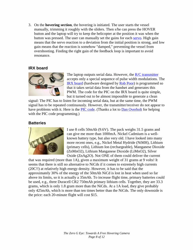
I use 8 cells 50mAh (9.6V). The pack weighs 31.5 grams and can give me more than 1000mA. Nickel Cadmium is a well-known battery type, but also very old. I have looked into many more recent ones, e.g., Nickel Metal Hydride (NiMH), Lithium (primary cells), Lithium Ion (rechargeable), Manganese Dioxide (ZnMnO2), Lithium Manganese Dioxide (LiMnO2), Silver Oxide (ZnAg2O). Not ONE of them could deliver the current
that was required (more than 1A), given a maximum weight of 31 grams at 9 volts! It seems that there is still no alternative to NiCds if it comes to extremely high currents (20C!!) at relatively high energy density. However, it has to be said that the approximately 30% of the energy of the 50mAh NiCd is lost in heat when used so far above its limits, so it is actually a 35mAh. To increase flight time, primary batteries could be used, e.g., three Duracell CR2 750mAh primary lithium cells. Together, they are 33.3 grams, which is only 1.8 gram more than the NiCds. At a 1A load, they give probably only 425mAh, which is more than ten times better than the NiCds. The only downside is the price: each 20-minute flight will cost $15.

The Zero G Eye: Towards A Free Hovering Camera Page 9 of 12
Propulsion
The Micro DC 5-2.4 is combined with a gear of 1:6.7 ratio, a double ball-bearing carbon output drive shaft with diameter 2 mm, and a molded carbon fiber propeller. The manufacturer says that at 9 volts, this propulsion set takes 1.06 A current, produces 9.5 Watts, spins the propeller with 4210 rpm, and delivers 91 grams of thrust; the gear efficiency is supposed to be 93%, which is remarkably high. The motor itself has a
maximum efficiency of 75.3% at its rated 5V, but probably much lower in this propulsion configuration. Due to the fact that the DC 5-24 is built to produce 2.45W at rated 5V, it will live only 5-15 hours when driven with 9.6V. After that, the brushes will have to be replaced. (Thanks a lot to Kai Huber for correcting me with the gear/motor efficiency. He has an incredibly interesting German page about electro motors, gears, and propellers for slow flyers.)
Servos
The WES servos are the lightest (2.4 grams) commercially available servos. Although servos like the Futaba Hitec HS-50 are only 30% bigger in size, they weigh twice as much (5 grams). The question was only if the output torque of 175 grams would be enough, but during the tests I did, it seemed to be enough to drive the flaps and rudders. However, it has still to be determined if the occasional stalling of the servos is due to too low voltage, too high force, or a messed up pulse width
modulation signal from the IRX board.
Receiver
The receiver is the lightest available with truly proportional four channels. If the weight of the receiver has to be reduced even more, the plugs can be removed and the servos could be soldered directly to the board. Alternatively, products like Z TRON’s infrared transmitter/receiver would weigh even less, but probably require line of sight.

The Zero G Eye: Towards A Free Hovering Camera Page 10 of 12
Electronic Speed Controller
The speed controller weighs less than one gram and is a very advanced piece of equipment (RISC processor, Auto-Calibration, Safe-Start): it provides a very smooth output voltage due to a clock-frequency of 60kHz. Additionally, it powers the receiver, so that no special receiver battery is necessary.
Gyro
Without its plastic case, the PG-03 is definitively the lightest gyro with electronics (5 grams). Note that the heading angle of the vessel is NOT controlled by the laptop: the computer has no information about the heading angle. Therefore, the gyro controls the yaw servo on its own. However, since it is NOT a headlock gyro, eventually, due to added up position errors, the vessel will lose its original heading angle. A deviation of more
than 30 degrees from the initial position would make the helicopter crash inevitably, since the control program would confuse the X and Y-axes. (Solutions to solve this problem are on the way.)
Ultrasonic beeper
The main idea behind this vessel is that absolute position is enough to stabilize a small helicopter. So the only sensor is this ultrasonic beeper. It is taken from the ring of a FreeD mouse, a wireless joystick. The ultrasonic sensor is from a 3DZ, a similar product based on the same technology. The beeper sends some kind of ultrasonic chirps and is probably synchronized with the sensor sitting on the floor via infrared. Line of sight between the beeper and the sensor on the floor is absolutely necessary,
especially for the infrared link.
Ultrasonic sensor
The sensor is an “L”-shaped piece of plastic, with three ultrasonic transducers on the corners, as well as an IR sensor in the middle. It is connected via serial port to the laptop.

The Zero G Eye: Towards A Free Hovering Camera Page 11 of 12
R/C transmitter
The radio handset takes the PWM signal from the IRX board and transmits it to the receiver on the vessel. Almost any kind of brand and model could be used for this purpose; it just has to have a trainer cord plug. I have used a Futaba 6XA, a standard 6 channel model. Having real joysticks "in the loop" makes it also easier to conduct pre-flight checks, testing the transmission and the servos. To switch to the trainer cord input and let the
computer control the servos, the user has to keep pressing a button on the upper left side of the handset. As soon as s/he releases this button, the handset (and hopefully a qualified pilot on the joysticks...) takes over the control over the vessel.
Current prototype vessel
Note: This vessel hasn’t flown yet! Although all subsystems and elements are working properly, including propulsion, I first want to charge the batteries properly, and then make sure the helicopter can’t crash easily. To do that, I will build some kind of scaffold or suspension.
Future improvements
• Make carbon fiber ring around propeller and flap hinges • Replace balsa flaps with carbon fiber ones • Get real clevises

The Zero G Eye: Towards A Free Hovering Camera Page 12 of 12
• Replace styrene fuselage square tube with carbon fiber one • Hang vessel from ceiling and/or walls with elastic ropes for test flights • Find reason for occasional stalling of servos, which makes them draw up to 600-
800mA current • Mount camera and transmitter • Look for a head lock gyro, or perhaps magnetic heading sensor and additional
serial back channel • Test other absolute position sensors, like Polhemus • Think about simple sensor scenarios that are independent from a ground station,
like measuring optical flow of an upwards looking Artificial Retina chip • Add a speech interface to the PC software, e.g., using IBM’s ViaVoice
After having finished my class project, I did extensive studies on the prototype and found out many serious flaws and problems that I did not foresee earlier. Essentially, my prototype cannot fly in configuration described above. I will write a report about these findings as soon as I find the time.