t./hebler (wes) mod l operational ev9l - apps.dtic.mil · .im. t./hebler (wes) mod l operational a....
TRANSCRIPT

ELECTRONIC COMPUTER PROGRAM ABSTRACTLLr" Cr as' OGRAM /i•
H7780 - Wave Runup and Wind Setup - Computational Model§ " J723-X6-MO07A.
Southwestern Division, Corps of Engineers, 1200 Main Street, Dallas, TX 75202AUT OR,(SY. D AT9 POGRAM COMPILETEO STATUS OF PROGRAM1, B . ,..... io;::
1+; - ' ~evisedi/Jun 78 iMD toa
.im. T./Hebler (WES) MOD l OperationalA. unp O"r PUWUA
The program provides a uniform method for calculating wave runup and wind set-up at the edge of lakes and reservoirs. Elevations of wave runup can becomputed for embankment slopes that are either smooth, turfed, or riprapped.References: Refer to Appendix A.
oL +IS. PROGRAM SPECIFICAIONS % ppS
SEE FOLLOWING PAGE . EV9LC. NET HOS
The program is written in G635 time-share series, FORTRAN IV, and is part ofa Conversationally Oriented Real-Time Program-Generating System (CORPS).
0ID. EQUIPMENT DETAILSThe basic program was developed on CDC 7600, Southwestern Division, Dallas, TX.The revised computer version in this abstract is now operational on the WES
L G635, Vicksburg, MS; HIS 66/80, Macon, GA; and Boeing CDC, Seattle, WA.
ff. 14PUTOUTPUT
All inputs for program H7780 are either read from a permanent data file orare cued and read upon entry to the input subroutine H77801. All specificinput/output requirements for program H7780 are given in PART II: COMPUTER. ! FUNCTIONAL DESCRIPTION of this abstract.
P. ADDITIONAL REMARKS
S The basic program was developed by B. R. Bodine, primarily besed on the infor-nation presented in ETL 1110-2-221, "Wave Runup and Wind Setup on ReservoirEmbankments" by Bruce L. McCartney. The coding has been revised at WES inorder to accommodate the CORPS time-share feature. , 1
IAUG 40 213 PIVIOUS DI TIONS ARE OSLETE.
H7780
B. PROGRAM SPECIFICATIONS:
Language: ANSI FORTRAN (FORTRAN IV)
Solution Requirements: The run command
RUN WESLIB/CORPS/H7780, R
and all necessary inputs.
Method of Analysis: Wave runup and wind setup are solved by direct
solution of algebraic equations except for the transitional depth
wave length which is solved via an interactive technique.
Core Requirements G635: 15 K words
External Storage: Type of storage - disk. Each user may have an
existing input data file with a maximum of 12 K G635 ASC II words.
If the file does not exist, a user named file is created. If user
decides to save tabulated output for graphics and/or other use, each
output file may have a maximum of 12 K G635 ASC II words. This file
may already exist or be created by the user during a run of H7780.
Restrictions: Refer to pages 18-22
General Equations: Refer to equations 10-18 as presented on
pages 14-17.
Range of Quantities: Unlimited for practical application. /Z
//
Accuracy: Governed by accuracy of input data. iqb , -,
.h • ''' "
40

pI
H7780
REF: ER 1110-1-10 - ENGINEERING AND DESIGN - Engineering ComputerProgram Library Standards and Documentation, Appendix B
PART I: ENGINEFRING DESCRIPTION
1. PROGRAM NUMBER: 723-X6-MO7A
2. TITLE: H7780 - Wave Runup and Wind Setup - Computational Model
3. REVISION LOG: Program coding revised June 78 to accommodate the
CORPS time-share features.
4. PURPOSE OF PROGRAM: To provide a uniform method for calculatinF
wave runup and wind setup at the edge of lakes and reservoirs. Eleva-
tions of wave runup can be computed for embankment slopes that are
either smooth, turfed, or riprapped.
References: Refer to Appendix A.
5. STEP SOLUTION:
a. Introduction:
The computer program outlined in this abstract has been developed
specifically for estimating wave runup and wind setup at the edge of
lakes or reservoirs. This program may also be used to estimate the
elevations of wave runup at the edge of semienclosed water bodies such
as bays and estuaries. However, the method used in the present solution
scheme for estimating wind setup is not generally appropriate for semi-
enclosed water bodies. The principles involved and estimating pro-
cedures used in developing the program are presented together with the
limitations of the computational system. Example problems involving the
determination of wave runup and wind setup in more or less typical lakes
1

H7780
or reservoirs are presented to demonstrate the utility of the program
and procedures necessary for application.
This abstract is not intended to stand on its own but rather serve
as a supplement to ETL 1110-2-221 (McCartney, 1976) references in
Appendix A. Inasmuch as the referenced ETL is self-contained in respect
to estimating characteristics of wind-generated waves for deepwater
conditions, guidance for estimating waves for transitional water and
shallow water conditions is referenced to the Shore Protection Manual
(1977). In the determination of freeboard allowances for high dams,
water depths are usually deep and thus it is usually necessary to esti-
mate wave runup on waves generated in deep water or nearly deep water.
However, in some instances, the design of some slope protection mea-
sures, such as highway and railroad embankments and flood levees, the
water depths over the wave generating area may be small and require that
the wave characteristics be based on transitional water or shallow water
conditions. Consequently, the present computational scheme includes
wave prediction for both deep, transitional, and shallow water.
The program has been formulated in such a manner that the prepara-
tion of basic data is minimized. In addition, provisions have been made
to allow determinations of wave runup and wind setup for one or more
sites with a single computer run.
b. Input: The inputs are read from existing user input data file
or are entered at run time via the user's input terminal device. The
2

H7780
inputs are described in PART II: COMPUTER FUNCTIONAL DESCRIPTION,
Part B, INPUT DATA DESCRIPTION.
c. Mathematical Formulation:
1. Design Wind. In the present program two options are provided for
describing the design wind. The first of these is simply the specifi-
cation of the design wind for a particular location based on actual wind
records representative of the area. For this option the overland wind
speed, UL , in miles per hour is a basic input to the program. The
overland wind speed is converted to the wind speed over water internal
to the program based on previously adopted criteria presented in
ETL 1110-2-221. These criteria relate the ratio, R , wind speed over
water and land areas to the effective fetch, F , for wave generation
as follows.
F (miles) 0.5 1 2 3 4 5 (or over)
UoverwaterR = 1.08 1.13 1.21 1.26 1.28 1.30u U overland
For convenience in programing the relationship, the ratio, Ru , is
presumed to approach unity as the fetch approaches zero.
In the absence of sufficient wind observations for a particular
site, the design wind may be determined from the averaged maximum
regional wind data provided in ETL 1110-2-221. For this case, the maxi-
mum 1-minute and 60-minute averaged winds for a specific location are
determined from the appropriate figures (Figures 2 through 9) in the ETL.
These overland wind speeds are a basic input to the program. The
3

H778o
adjustment to overwater wind speeds are determined internal to the
program. Moreover, the design wind speed is calculated by a program
subroutine. The techniques and procedures used for calculating the
design wind speed is discussed in Appendix B.
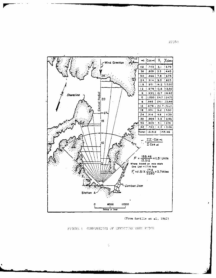
2. Effective Fetch for Wave Generation. In the present computational
scheme the effective fetch distance for wave generation is determined
in accordance to the method developed o.) Saville et al. (1962) and out-
lined in ETL 1110-2-221. The procedure for determining the effective
fetch distance, F , by this method is illustrated in Figure 1. It con-
sists of superimposing radials on a suitable map which depicts the water
body. The radials are constructed in a manner so that they emanate from
the shoreline site where wave information is needed and extend across
the water area until they intersect the shoreline. Even though some of
the radial lengths may be zero, the central radial taken alonF the long-
axis of the water body will usually result in the longest effective wave
fetch. The interval between any two adjacent radials is taken as
6 degrees (angle denoted by the symbol, a , on Fitgure 1) and the
radials are limited by an angle of 45 degrees on either side of the
wind direction. As a result of the bounds indicated, 15 radials are
used in the determination of the effective fetch.
In the application of the effective fetch method in practice, ques-
tion sometimes arises as to whether the radials have been constructed
properly for maximum wave generation. On this basis, provisions have
been made in the present computational scheme to input more than 15
L.Wind Oirection WI23l .7
36 8.C9 f5.5 4.45
3 0 .866 1 7.8 6.7 5
2 4 .914 1 9.0 8.23
I a .951 1 4.2 113.!012 .976 1 3.8 13.50
Shoreline6011.001 24.7 1 24.7C
(.925 24.1 -3.9ei2 1.9 78 2 Z. 7 i zzC
IS81.951 6.2 1 5.50
30 1.866 1 3.3 2.86
42Z .743 1 2.2 i .08j
10ital 113.512 1155.46
I F .4 =11.51 Units
Where based o~n~ MC sal/ / One Umt - 1714 feet
0 6000 12000
Scale in~ feet
(From Saville et al, 1962)
FIGURE I CON IUTATI ON OF EFECT? VE Wv AVE F C

11778o
radials, if desired. A special routine is included in the program to
determine the effective fetch with the greatest length (referred to
hereafter as the critical effective wave fetch) from a particular set of
15 sequential radials. It is to be noted, however, that a minimum of
15 radials are required as a basic input to the program.
3. Effective Fetch for Wind Setup. Fetch distance for use in estimat-
ing wind setup can usually be taken considerably longer than fetch dis-
tance used for wave generation. This is because wind setup effects may
be transferred, to some extent, around substantial bends in the water
body, thus warranting the assumption of a longer fetch. Guidance pro-
vided in ETL 1110-2-221 indicates that the wind setup fetch, Fu , can
be estimated by using twice the effective wave fetch. For most probleims
encountered in practice, this is a sufficient estimate of the wind setup
fetch. However, for some problems such an estimate may not always be
realistic. Consider the example that all radial lengths are approxi-
mately equal for a given wave generation area. This would imply, as can
be rhown, that the effective wave fetch is approximately equal to 88
percent of the central radial length. Because of this particular con-
dition, the wind setup fetch would exceed the central radial length by
about 76 percent when using twice the effective wave fetch. As a conse-
quence, this would infer that a portion of the wind setup fetch would be
over water and another portion of the fetch would be over land. in the
present computational scheme, this possibility is avoided by rcstrictin 7
the wind setup fetch to a distance less than or equal to the lonfest
6

H7780
radial length. Sl)~:c if:ically, the wind setup fetch is equal to twice the
effective wave fetch if this distance is less than the longest radial
and equal to the longest radial if 2 F is longer than the longcnt
radial.
4. Wave Char:LCtcristics. The most fundamental description of waves in-
duccd by Hind is their length L , height H , period T , and the wave
depth d (see Figure ~~) . Inasmuch as wind waves are merely a more or
less rhythmic chan!~C in the elevation of the water surface with ensen-
t.!.ally no net, tran~;nort of the water, the wave form propagates in the
direction of -:;he \vind by a velocity equal to L/T . This velocity is
referred to ~t~; t~hc pha:;e velocity or wave celer:L ty.
Sur fn.ce ·w-:tv(~~~ induced by wind are classified in accordance to their
lengths and the depths of \mter over which they travel, or specifically
by ratio d/L . 1\ 'vw.ve is said to be a "deep water wave" if d/L is
greater th::.n l/2, :l "transitional wave" if d/L lies in a range between
l/2') and .L/2, aml 1'- "c;hallow water wave" if d/L is less than l/25.
Tl1e characteristics of deepHater waves are unaffected by the depth over
which they propagu.tc. On the other hand, waves in transitional and
shallow wnte2· arc affected by the depth in which they run, resul tine;
}Jrimarily in tlw modif:i cation of the wave form. It ir> of~ten said that
transitional and shallow water waves feel bottom.
Observing waves under the influence of Hind reveal that there is
J.L tt1c ret';Ul:n·i Ly in ,,m.vc form and the elevatl on~> of tl1e rise and fn.ll
of the Hflter :_;urf.·tc~c'. When attention is focw;ed on say 1,000
'(

H7780
UU
S
0
. . .. .2.. . .. .- .. . . . . .. . . . I F - .. . . '-m Ii ..

H7780
consecutive waves, referred to as a wave train, passing a fixed location
it will be seen that there is considerable irregularity in wave form and
wave height. Once the waves leave the generating area, the waves con-
tinue to propagate in the direction the wind was blowing, but they begin
to transform into waves of more regular shape and more uniform height.
In the solution of engineering problems for reservoirs and lakes, wave
analysis is almost always concerned with waves under the influence of
wind. Thus in dealing -with such problems it is necessary from a theo-
retical point of view to represent the waves by an idealized description
of the water surface. To facilitate this description a wave referred to
as the "significant wave" has been postulated in which this wave has
been almost universally adopted for the solution of wave problems. The
significant wave height is defined as the average height of the one-
third highest waves and written as H sor H 13.The wave period
associated with such a wave is called the significant wave period, T
Occasionally, in the planning and. design of shore structures it is
advantageous to consider other waves in the wave spectrum for particular
design analysis. This stems from the fact that in some instances it may
be necessary or appropriate to provide a higher or lesser degree of pro-
tection than that afforded by the significant wave. Al1tering the degree
of protection may be accomplished by selecting a specific wave height
greater or smaller than the significant wave height. Other wave heights
may be obtained and based on a knowledge of the significant wave height
and utilizing the Rayleigh distribution function. The wave height
H7780
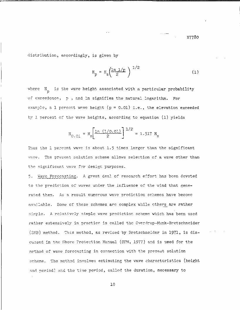
distribution, accordingly, is given by
H = H 1n 1/p ( )
1/2
p s 2 (1)
where H 1s the wave height associated with a particular probability p
of exceed.cnce, p , and. 1n signifies the natural logarithm. For
example, a 1 percent w~ve height (p = 0.01) i.e., the elevation exceeded
by l percent of the wave heights, according to equation (1) yields
H = H [1n (1/0.01)] 1/2 = 1.517 H ··o. 01 s 2 s
Thus the l percent wave is about 1.5 times larger than the significant
wave. The present solution scheme allows selection of a wave other than
the significar.t '.mve for design purposes.
5. 1-Jave Forecasting. A great d.ea1 of research effort has been devoted
to the prediction of waves under the influence of the wind that gene-
rated them. As a result numerous wave prediction schemes have become
available. Some of these schemes are complex while others are rather
:Jimple. A relatively simple wave prediction scheme which has been used
rather extensively in practice is called the 3verd.rup-Mtmk-Bretschneider
(SM.B) method. Thi.s method, as revised by Bretschneider ln 1971, is dis-
cussed in the Shore Protection Manual (SPM, 1977) and is used for the
method. of wave forecasting in connection with the preserlt solution
scheme. The method involves estimating the wave characteristics (height
and period) and. the time pe:riod, called the duration, necessary to
10
H7780
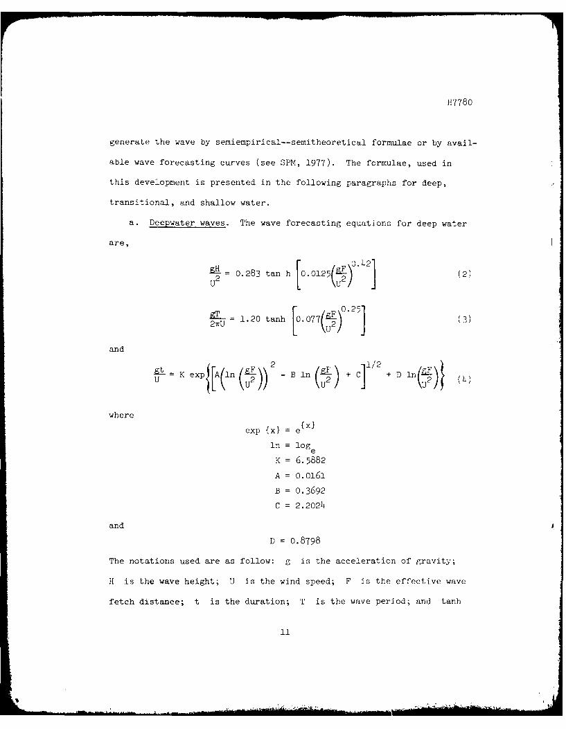
generate the wave by semiempirical--semitheoretical formulae or by avail-
able wave forecasting curves (see SPM, 1977). The formulae, used in
this development is presented in the following paragraphs for deep,
transitional, and shallow water.
a. Deepwater waves. The wave forecasting equations for deep water
are,
H 0.283 tan h 0.0125 (2)
gT 1.20 tanh L.077()1 (3
and
t K exp{[A(ln (i)) - B ln (L) + C] + D ln( 2)}
where
exp {x} = e{x)
ln = log e
K = 6.5882
A = 0.0161
B = 0.3692
C = 2.2024
and
D = 0.8798
The notations used are as follow: g is the acceleration of gravity;
H is the wave height; U is the wind speed; F is the effective wave
fetch distance; t is the duration; T is the wave period; and tanh
1i
.m., t

H7780
is the hyperbolic tangent. Equations 2, 3, and 4 are nondimensional;
and consequently, any system of units may be used. Units consisting of
feet-seconds are used in the present computational scheme.
Subsequent to the determination of the wave period, the wave length
in deep water L may be calculated by0
L gT2 5.12 T2 (ft) (5)o 27T
This relation shows that the length of the wave in deep water is unaf-
fected by the depth in which the wave travels (i.e., where d/L > 0.5).
b. Transitional and shallow water waves. Wave generation and wave
characteristics are affected when waves are traveling in transitional
and shallow water depths. For a given set of wind and fetch conditions,
wave heights will be smaller and wave periods shorter in comparison to
those in deep water.
The numerical technique presented here is based on successive
approximations in which wave energy is added due to wind stress and
subtracted due to bottom friction and percolation.
The equations applicable for transitional and shallow water condi-
tions which incorporate bottom friction are as follows:
0.283 tanh 0.530( tanh 0.(5(6)
12
H7780
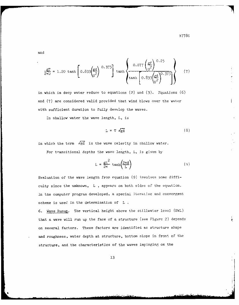
and
0.7 (gF) 0.25
- 1.20 tanh 0.833 .7 (2 TU ( U t a n 0 .0 7 73 7ti3~ku2) tanh [.833()3 __ 1
in which in deep water reduce to equations (2) and (3). Equations (6)
and (7) are considered valid provided that wind blows over the water
with sufficient duration to fully develop the waves.
In shallow water the wave length, L, is
L = T YrgI (8)
in which the term Yg-d is the wave celerity in shallow water.
For transitional depths the wave length, L, is given by
L=27T tanh- L (9)
Evaluation of the wave length from equation (9) involves some diffi-
culty since the unknown, L , appears on both sides of the equation.
In the computer program developed, a special iterative and convergent
scheme is used in the determination of L .
6. Wave Runup. The vertical height above the stillwater level (SWL)
that a wave will run up the face of a structure (see Figure 2) depends
on several factors. These factors are identified as structure shape
and roughness, water depth at structure, bottom slope in front of the
structure, and the characteristics of the waves impinging on the
13

H7780
structure. Because of the large number of variables involved and possi-
ble combinations of geometric shapes and wave conditions, an accurate
description of wave runup phenomena is not available. However, a great
deal of useful guidance has become available for estimating wave runup
as a result of numerous laboratory studies conducted by using mechanical
generated waves and some field studies. Seville (1955, 1956) Savage
(1959), Saville et al. (1962), Batties (1974), and Ahrens and McCartney
(1975), among others, present the results of such studies.
A large number of laboratory experiments were conducted for runup
on smooth plane slopes in 1956 (Saville, 1956). The results of these
experiments were reproduced in graphic form and are presented in the
recent Shore Protection Manual (1977). In 1965, Franzius, a German
Engineer, transformed these graphical runup results into formulae which
are convenient for computer applications. The relations obtained, as
given by Battjes (197)4), are as follows:
R = H sin 9 (5.95 tan 9 + 1.5) (0.123 L)a (10)
where the exponent a is given by
a =Fs(1.58 - 2.35 tan 9) + 0.092 cot e 0.26 (11)
in which R is the wave runup, d sis the depth of the water at the
toe of the embankment, and 9 is the angle between the horizontal and
the embankment slope. Equation (10) is valid for

117780
1/6 < tan o < 1/2.25 and Li- < 0.475 (12)d
For a 1 on 1.5 slope the following equation is given
= i (13)
For slopes flatter than a 1 on 6 slope, a formula g-iven Battjes
(1975) is used to estimate the wave runup. This equation is given by
= 0. 4 T gl tan 0 ',
Franzius also found from experiments that the runo on smooth slopes
could be modified to account for turfed slopes by the following- approxi-
mate relation
RT = (0.85 to 0.90) Rs (15)
in which RT is the runup on a turfed slope and Rs is the runup on a
smooth slope. In other words, the runup on a turfed slope is about 85
to 90 percent of the runup on a smooth slope. An approximate relation
similar to equation (15) may also be 'ziven for impermeable stepped
slopes in which the vertical and horizontal dimensions of the steps
are relatively small compared to the wave heiglht. Such a relation ik
given by
RT = (0.7 to 0.8) R W')
15

H7780
The factors 0.7 to 0.8 were based on data presented in SPM (1977) for
stepped slopes and private communications with John Ahrens, Oceanogra-
pher, Coastal Structures Branch, Coastal Engineering Research Center.
For solution of other engineering problems, it is reasoned that
runup for smooth slopes can be modified in the same manner for other
slope surface conditions provided that the slope is uniform and the
embankment surface is relatively smooth. Such a modification would not,
however, be applicable to extremely rough slope surfaces.
In the case of riprapped embankment slopes, the relation given by
McCartney (1976) provides a reasonable estimate of the runup. This
relation is given by
R1/2 (17)o.4 + (H/Lo) cot e
Equation (17) is considered valid for 2 < cot 6 < 5
The equations given herein for estimating runup will normally be
sufficient for resolving most problems encountered in reservoirs and
lakes.
7. Wind Setu. The action of wind blowing over water surfaces of lakes
and reservoirs is not only responsible for generating surface waves but
causes the water surface to tilt from the windward side to the leeward
side of the basin. The tilt is a result of the wind inducing a current
in the upper layers of the water in the direction of the wind and thus
causing the water to pile up at the leeward shore. A return current,
16

H7780
smaller in magnitude than the wind induced surface current, is
established along the bottom in the opposite direction of the wind.
At the upwind side of the basin the water level is depressed and at the
downwind side the water level is raised as a result of the unequal sur-
face and bottom current. The rise in water level at the downwind side
of the water body is referred to as wind setup. The prediction of' wind
setup is complex due to the number of mechanisms and processes involved
and the complications that arise in simulating the basin geometry. Al-
though wind setup can be estimated with a reasonable degree of accuracy
by sophisticated mathematical models presently available, there is
usually little justification to do so for relatively small arid deep
lakes and reservoirs due to the substantial effort and expense in apply-
ing such schemes and the fact that wind setup is rather small in com-
parison to the wave setup.
A relation which in general gives a reasonably m]ood estimate o
the wind setup (see McCartney, 1976) is
U2 FS = 1440 D
in which S is the wind setup in feet; U is the wind speed in miles
per hour; F is the wind setup fetch in miles and D is the aver'i-eu
depth over the wind setup fetch in feet.
Equation (18) will generally provide conserw.tive wind sttuj ct
mates at all locations in a relatively deepwater body cxcupt at the
17

177 8(
locations where tVe basin geometry converges to the shore site where
interest is centered. For sites located in a highly convergent zone it
may be justified to increase the wind setup as much as 50 percent to
account for an additional pileup of water.
d. Out-put: The output consists of three parts; basic input, corn-
putational results, and user option output. The basic input and compu-
tational results are printed for each problem. The user option output
(Wind Data and Deepwater Wave Characteristics and Wave Heights and Wave
Runup for Waves Other Than the Significant Wave) is or is not printed
according to user specification in the basic input. The tabulated out-
put (user option output), if desired, may be stored in a user existing
or run-time created output data file.
6. ACCURACY: Governed by accuracy of input data.
7. REMARKS:
a. General. Inasmuch as the computational model described herein
will usually provide a reasonable estimate of wave runup and wind setup
for most problems encountered in practice, there are some practical
problems in which the model cannot be expected to yield meaningful
results. Because the model is not applicable to all problems, care
must be exercised in determining the practical limits in which the model
can be applied. Determination of whether the model is applicable or
not applicable to a specific problem area requires a careful review of
the physical characteristics of the water body and embankment coupled
with engineering judgment.
18

H7780
The model is limited to the determination of wave runup on uniform
smooth, relatively smooth, and riprap slopes with waves approaching from
a direction normal (90 degrees) to the slope. It is also applicable to
stepped slopes in which the vertical and horizontal dimensions of the
steps are small in comparison to the wave height. The model is not ap
plicable to other nonuniform slope configurations, vertical walls, and
for such slope covers as permeable rubble mound. Although the model
does not apply for the cases mentioned, wave runup estimates can usually
be made by the methods and procedures presented in SPM (1977).
The height and period of waves calculated in the model are deter
mined from empirical wave forecast formulae in which it-is assumed that
wave propagation over the fetch occurs with a uniform depth. However,
for real water bodies, depths can vary considerably over the wave fetch.
In many cases when waves propagate over the fetch, the wave in one por
tion of the fetch may be a deepwater wave while at another a shallow
water wave. However, a reasonable estimate of the height and period of
waves can be obtained by using the average depth over the fetch provided
t~at the wave does not break as it travels over the fetch. Theoretic
<Llly, a wave heitjht, H , cannot exceed 0.78d, where d is the local
vrater depth. \-laves breaking offshore from a structure result in a lower
wave height at the structure. Thus, the reduced wave height should be
~sed in determining the wave runup at the structure. No provisions
:1re made in the present model to account for breaking waves and, there
fore, it i~ necessary to account for this effect separately.
19

H778C
There are some instances when waves break along the path of wave
propagation at a considerable distance from the site where interest is
centered. For example, a roadway may transverse the water body at about
right angles to the wind direction at about mdiway along the wave fetch.
Under severe flooding conditions, the roadway may cause the waves to
break as they pass over the top of the road. For such cases, an esti-
mate of the design wave reaching the project site may be obtained by
first obtaining the breaking wave height, H b 1 over the roadway (i.e.,
Hb = 0.78 d-b), and then determining the fetch required to generate the
height of the breaking wave. The fetch necessary to generate the break-
ing wave may be determined from the appropriate wave forecasting curves
presented in the SPM (1977). This fetch added to the fetch between the
roadway and the project site can then be used to estimate the wave
height and wave period at the project site.
The following problem will illustrate the determinations required
to estimate the wave characteristics at a project site for the case wheni
a roadway traversing a water body alters the effective wave fetch.
EXAMPLE PROBLEM
GIVEN: A roadway crosses a reservoir midway between the upwind side of
the reservoir and the project site in which F, = FO = 20,000 feet.
The fetch F 1is the distance between the roadway and the upwind side
of the reservoir, and F 2is the downwind fetch. The wind speed, U
is 60 mph, di d d2 35 feet and the still water level is 5 feet above
20
1H7780
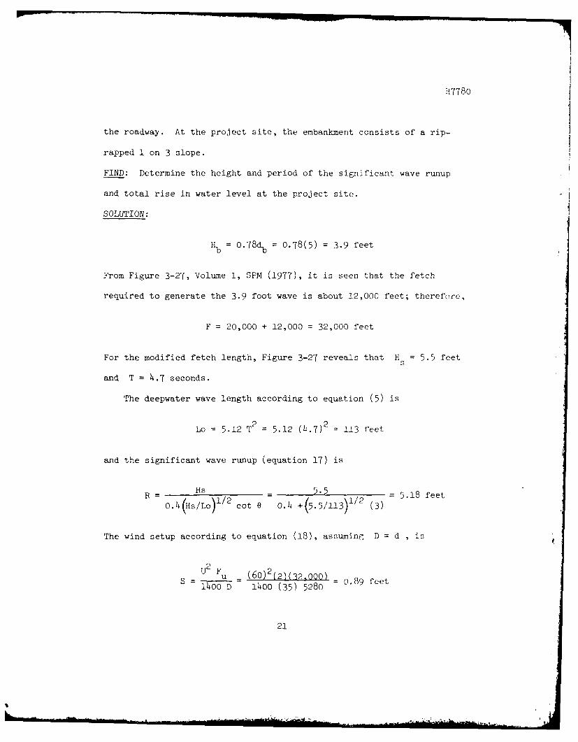
the roadway. At the project site, the embankment consists of a rip-
rapped 1 on 3 slope.
FIND: Determine the height and period of the significant wave runup
and total rise in water level at the project site.
SOLUTION:
Hb = 0.78db = 0.78(5) = 3.9 feet
From Figure 3-27, Volume I, SPM (1977), it is seen that the fetch
required to generate the 3.9 foot wave is about 12,000 feet; therefore,
F = 20,000 + 12,000 = 32,000 feet
For the modified fetch length, Figure 3-27 reveals that H = 5.5 feet5
and T = 4.7 seconds.
The deepwater wave length according to equation (5) is
Lo = 5.12 T2 = 5.12 (4.7)2 _ 113 feet
and the significant wave runup (equation 17) is
SHs 5.5 = 5.18 feeto.4(Hs/Lo)11/2 cot e 0.4 +(5.5/113) 1 2 (3)
The wind setup according to equation (18), assuming D = d , is
U2 Fu _ (60)2 (2)(32,000) = 0.89 feet1400 D 1400 (35) 5280
21
H7780
The total rise in water level at the project site is
S + R = 0.89 + 5.18 =6.1 feet
Finally, it should be noted that the model does not account for
wave modification as a result of refraction, diffraction, and reflection.
Reference is made to the Shore Protection Manual (1977) far treating
such wave phenomena.
b. Acknowledgements. Many useful comments and suggestions either
received or by personal communications have been extremely helpful to the
author in development of the computer program and preparation of this
report. In particular, a great deal of credit must go to R. A.
Jackowski, Coastal Engineering Research Center (CERC) for his useful
review comments and suggestions. Others who have made contributions
are R. L. Hula, of the Southwestern Division Office; M. A. Fly, of the
Tulsa District; B. L. McCartney, of the Office of Chief of Engineers;
D. L. Harris, of CERC; and J. P. Ahrens, of CEBC.
Finally, considerable credit must go to Mrs. K. J. Davis for edit-
ing and typing the report.
22

H7780
PART II: COMIPUTER FUNCTIONAL DESClII'TION
1. REVISION LOG: Program coding revised June 78 to accormodate the
CORPS time-share features.
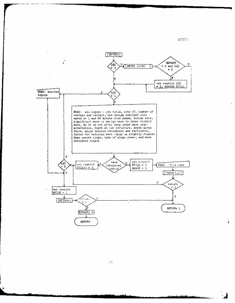
2. FUNCTIONAL FLOW CHART:
START
T
H778oi
rerun
F
C TODP
23

set constants
ENTRY H77803
set controlsSTART = 0 LQZ=lKFILE = 1
REA n v F perm.T Rie IEAD oK E d not conro
Read: Job title, site ID, number radials, type of slopecover, use overland wind speed or f and 60 minute wind szeed,design wave, significant wave or design wave is other
related wave, do or do not print deep water wave character-
istics, depth at toe of structure, depth along fetch, anglebetween embankment and horizontal, factor for reducing waverunup on slightly rougher than smooth slope, 1 and 60 mai
wind speed or overland wind speed and radials
O dLZset controlLQZ = 2
24
F ru

PRINT: basic data - job title, site ID, depthat toe, average water depth slope modificationfactor, 1 and 60 min or overland wind speed and
determine shaec low fete ts
weharacteristics ddrto fwn
requredto gnerte dep aterwav
25ep

H7 7 8o
22
177 F
[ENTRY H7780 =0 and LQZ T
set control LQZT = 2;'REWIND KFIL:: '
READ: desired.FT inputs, r =
READ: all inputs - job title, site ID, number ofradials and radials, use design overland windspeed or I and 60 minute wind speed, design wave,
significat wave or design wave is other relatedwave, do or do not print deep water. wave char-acteristics, depth at toe structure, depth along
fetch, angle between embankment and horizontal,factor for reducing wave runup on slightly roujner
than smooth slope, type of slope cover, and save
tabulated output
se to F s set control2e controle KFILE = 2 RA:fl
SA 0 outpu NSAVE = 1L F TACHFI 1
, II set controlIKFIUE I
/7
AbA

7W77w0
RETURN 1 'f r(irn
REWIND wFILE
WRITE to KFILE: program name 117780, ob title,
site ID, number of radials, type of slope cover,whether to use overland or 1 and 60 minute wind
speed, design wave factor, print option for deep
water wave conditions, depth at toe, depth aloni
fetch, angle between embankment and horizontal,slope factor, overland wind speed or 1 and (0minute wind speed and radials
NSTART=O
RETURN
Ja

H7780
TH7780iitTNSVE T READ KFILE: to/
skip header
TE to KFILE: header //for graphics
WRITE to KFILE: overwaterwind speed, wind duration,significant wave period,wave exceedance, wave
height and wave runup
i
29

3. EQUIPMENT AND OPERATING SYSTEM: The basic program was developed on
CDC 7600, Southwestern Division, Dallas, TX. The revised computer
version in this abstract was developed on a G635 time-share system in
which input/output equipment consisted of a Model 33 remote teletype.
It is now available on the WES G635, Vicksburg, ME; HIS 66/80, Pacon,
GA; and Boeing CDC, Seattle, WA.
4. INPUT REQUIREMENTS: The required inputs are:
a. Read, in the computational subroutine H7780, from a user
input data file.
b. Entered, in subroutine H7780I, via the user's time-shareterminal device in free field format. The inputs are passedto the computational subroutine H7780 via the CO.MiON state-ment.
5. SECONDARY STORAGE INPUT FORMAT: The formats for the user input
data file, whether it already exists or is created during a run of E7780,
are:
a. READ:
10260 FORMAT (4X,A8)
10350 FORMAT (hx,15Ah/4x,15A4/4x,5I3/hX,hFT.2,4X,2F7.2,7(/4X,8F7.2))
Refer to line numbers 10250 and 10330-10340 of the source listinr,
page 61.
b. WRITE:
16180 FORMAT (13,"H778o",2(/I3,lX,15A4)/I3,lX,513/3,1X,4Z7.P/13,
IX,2F7.2,7(/13,lX,8FT.2))
Refer to line numbers 16150-16170 of the source liP;ting, page 6'.
30

NY7780
6. INPUT DATA DESCRIPTION: The following names are used for the input
variables in program H7780.
COTTH - cotangent, angle between horizontal and embankmentslope. Example - slope of 1 on 2, COTTH = 2.0.
D - average water depth along wind fetch, ft
Dl - water depth at tow of structure, ft
FACT - factor for adjusting slope roughness for relativelysmooth slopes. FACT = 1.0 for smooth slopes; = 0.85to 0.90 for turfed slopes
FILEK(l) - 8 character variable for name of user input data f1<
FILEK(2) - 8 character variable for name of user output data filefor graphics and/or other use
IDES - factor io, design wave; 0, design wave is signific:nlwave; 1, design wave is some other wave in a reprertta-tive spectrum
IMM - number of radials in evaluation of critical effectivefetch; 15 minimum
X(I) - length of radials for I = 1,...,ir' 'iles
ITAB - print option for deepwater wave characteristics ofvarious wind speeds. ITAB = 1, print table of values;
0, no print
ITYPE - type of embankment slope cover. ITY]E = -1, riprap;= 0, smooth; = 1, other types
IWIND - factor for design wind. IWIND = 0, input overlandwind speed; = 1, input 1 and 60 minute wind speeds i:;provided in ETL 1110-2-221
UL - overla.id wind speed, mph
U2 - maximum 1 minute wind speed, mph
U61 - maximum 60 minute wind speed, mph
I

H7780
SITE - 15 dimension, 4 character variable for siteidentification
TITLE - 15 dimension, 4 character variable for job title
7. OUTPUT DATA DESCRIPTION: The following names are used for the out-
put variables in program H7780.
DL - design deepwater wave length, ft
FE - critical effective wave fetch, miles
FS - fetch for wind setup, miles
H - significant wave height (deepwater characteristics), ft
HD - design wave height, ft
HP - wave height for waves other than significant wave, ft
PPEP - wave exceedance. Exceedance refers to the percent ofwave in a wave spectrum that exceeds a given value,percent
RP - wave runup for wave other than significant wave, ft
RS - significant wave runup, ft above SWL
RSS - total increase in water level, ft above SWL
S - wind setup, ft
T - significant wave period (deepwater characteristics),sec
TD - design wave period, sec
TDUR - wind duration (deepwater characteristics), min
TDURD - design wind duration, min
UD - design wind speed, mph
UF - over water wind speed (deepwater characteristics),mph
32

H778o
8. PROGRAM ERROR MESSAGES:
Messages from subroutine TACHFILE. TACHFILE is a file handling
routine for CORPS H files.
a. If file name INDATA is entered as an existing, but does not
exist, then
NO SUCH FILE INDATA RE-ENTER NAME, Y OR N
is printed. If answer is Y, then the new file name is read and the file
is attached. A reply of N returns control to the main program.
b. If INDATA does exist, but cannot be attached, then
FILE PROB. CALL M T HEBLER AT 88-542-24o3 AND GIVE THIS
NUMBER ISTAT THANKS
where ISTAT is a 12 digit octal number. Control is returned to the
main program.
C. If INDATA is busy, then
FILE INDATA BUSY. ANOTHER FILE, Y OR N
is printed. If answer is Y, then the new file name is read and the file
is attached. If N, control is returned to the main program.
d. If IN:DATA, which has the illegal character : in its file namen
occurs, then
ILLEGAL CHAR IN FILE NAME IN:DATA RE-ENTER Y OR N
33

H7780
is printed. If answer is Y, a new file name is read and the file
attached. If N, control is returned to the main program.
e. If file INDATA is an existing attached file, but is not an
input file for H7780, then
FILE INDATA IS NOT AN INPUT FILE FOR 117780. RE-ENTER
Y OR N
is printed. If answer is Y, then the new file is attached and tested.
If N, control is returned to the main program.
f. If file INDATA is an existing attached file, but is not an
output file for H7780, then
FILE INDATA IS NOT AN OUTPUT FILE FOR h7780. RE-ENTER
Y OR N
is printed. If answer is Y, the new file is attached and tested, if 0.
control is returned to the main program.
9. VARIABLE DEFINITIONS:
a. Main Program:
HFILE - five character name of program; passed to WESIIB count
routine HACCT
LQZ - - equal i, call subroutine H77801 and execute all inputcues and reads; = 2, call WESLIB routine RERUN andenter only desired inputs
LQX - equal 1, print instructions for RERUN; = 3, no print
ZZZZZ - 2 character; = RE, rerun; = ST, ntop
34

H7780
b. Subroutine H7780:
ADIFF - absolute value of the difference between the trial transitional depth waye length and the value of equn.t ion ( 9) , page 13, ft
AI - wave exceedance in percent
ALEN - trial transitional depth wave length, ft
ALN ivorkinr; storage; equal to the expression A ln(B!:.u~ )2 of
equation (4) page 11.
ALPHA(I) - angle between a specific radial line and the central radial, for I= 1, ... ,15, radians
AU - addition counter; adds 1 to over water wind speed for for each print, until maximum number of prints reached for wind data and deepwater wave characteristics
AU360 - r.atural log of wind speed for duration of 360 minutes, mph
AU60 - natural log of maximum 60 minute wind speed, mph
AO - working storage; equal to the expression exp(ln u6 -A ln 60) of equation (B-4), page B-3, Appendix B
Al - absolute value of the reciprocal of the difference ratio between the natural logs of 60 and 360 minute wind speeds to the natural logs of 60 and 360
A60 - natural log of 60
A360 - natural log of 360
BLEN - value of equation (9) page 13 at trial transitional depth wave length, ft
BLN - workinrr, storage; equal to the expression l3 ln(~) of equation (4) page 11 U
C - equal to 22/15; changes mph to fps
COT'l'H - cotangent; angle between embankment slope and hori-~ontal. Example, slope of 1 on 2; COTTH = 2
35

H7780
D - average water depth along wind fetch, ft
DIFF - difference between trial transitional depth wavelength and the value of equation (9) page 13 at trialtransitional wave length, ft
DL - design deepwater wave length, ft
DLN - working storage; equal to the expression D ln (EF) of'equation (4) page 11.
DS - depth at toe of structure plus wind setup, ft
Dl - depth of toe of structure, ft
F - effective fetch, miles
FACT - factor for adjusting slope roughness for relativelysmooth slopes. FACT = 1, smooth slope; = .85 to .9,turfed slopes
FE - effective fetch (critical), miles
FES - effective fetch (critical), ft
FI(I) - fetch increments used in determininF the factor forconverting overland wind speed to overwater wind speedfor I = 1,...,7
I F1 I FI I F!1 0 2 .5 3 14 2 5 3 6 4
7 5
FILEK(l) - 8 character name of input data file
FILEK(2) - 8 character name of output file for 1raphics and/orother use
FILET - 5 character name of COREIS H-file used to build inputdata file or output file for graphics and/or other use
FS - fetch for wind setup, miles
GD(I) - constants for equation (1) page 11 for I = 1,...,5
36

H7780
I GD I GD I GD
1 6.5882 2 0.o161 3 0.36924 2.2024 5 0.8798
GDU - working storage; equal to the expression Ed of equa-
tions (6) and (7) pages 12 and 13 U2
GFU - working storage; equal to the expression gF of equa-U2
tions (2), (3), and (4) page 1i and equations (6) and(7) pages 12 and 13
GH - working storage; equal to the expression tanh
.0125 2 of equation (2) page 11 and equation
(6) page 12.
2GRAV - acceleration of gravity, 32.2 ft/sec
GT - working storage; equal to the expression tanh
(077 )2 of equation (3) page 11 and equation (7)
page 132
GTA - working storage; equal to the expression of equa-
tion (9) page 13
GTB - working storage; equal to the expression 2zd of equa-
tion (9) page
GI - working storage; equal to the expression tanh
02 (.2x75 of equation (6) page 12
G2 - working storage; equal to the expression tanh
(833(d .37 5 )of equation (7) page 13
G3 - working storage; equal to the right hand-side of
equation (6) page 12
G4 - working storage; equal to the right hand-side of
equation (7) page 13
37¢

H(I)
l'"'"~ .1.1~
H:?I:GE
HP(I)
IDES
IFII'J
n
IJK
- significant wave height for wind data and deepwater wave characteristics, I= 1, ••. ,IX; ft
- design wave height, ft
H7780
- 5 character name of program's CORPS H-file name (H7780)
- wave heights for waves other than the significant wave, for I= 1, ... ,20;ft
- factor for design wave; IDES = 0, design wave is sig~ificant wave; = 1, design wave is some other related wave
switch; = 0, read angles between specific radial lines and central radial line from 42° down to 0°, = 1, read back up from 6° to 42°
- counter in determination of effective fetch; = 1 if 15 radial lengths input; if > 15 radial lengths entered, increased one each time effective fetch scheme is entered until = number of radial lengths input - 15 + 1
- counter in determination of effective fetch; = 15 if 15 radial length input; increased one each time effective fetch scheme is entered until = number of radial lengths input
IK - nnmber of first radial length corresponding to criti-cal effective fetch to be printed
IL - number of last radial length corresponding to critical effective fetch to be printed; = IK + 14
Ir<li'vi - number of radial lengths input
INC - counter used in determination of deepwater wave charac-
TT!~B
teristics; increased by 1 until a fetch increment used in determining the factor for converting overland wind spe0d to overwater wind speed is found ~to the critical effective fetch
- option for printine tabulation of deepwater wave characteristics; ITAB = 0, no print; = 1, print
38

H7780
ITYPE - type of embankment cover; = -1, riprap; = 0, smooth;1 1, other types
IUD - integer used to convert design wind speed to aninteger value, mph
IWIND - factor for design wind; = 0, input overland designwind; = 1, wind values input from data provided inETL 1110-2-221 (1 and 60 minute wind speeds)
IX - total number of values of outputs to be printed forwind data and deepwater wave characteristics
J - counter in determination of effective fetch; keepstrack of which angle between a specific radial lineand the central radial line to use in the computations
KFILE - logical file designator for input data file and outputfile for graphics and/or other use; = 1, input file;
= 2, output file
LQX - equal 1, print instruction for RERUN; = 3, no print.No function in this subroutine (H7780), just uses COlD"c':1;
to be passed to input subroutine H7780I
LQZ - set equal to 1 if no permanent input data file exists;set equal to 2 if file exists. If = i, execute cue"CHANGE ANY DATA BEFORE RUN, Y OR N"
NSTART - set equal to 1 if permanent data file exists and thisis first entry to file; set equal 0 if no permanentfile or permanent file has already been entered.If = 1, execute cue "CHANGE ANY DATA BEFORE RUN, YOR N"
NSAVE - equal 1 or 2, save tabulated output for graphicsand/or other use; = 0, no save
P - wave exceedance in hundredths
PI - constant = 3.14159265
PPEP(I) - wave exceedance in percent for I = 1,...,20
R - ratio of overwater wind speed to overland wind speed
39
H7780
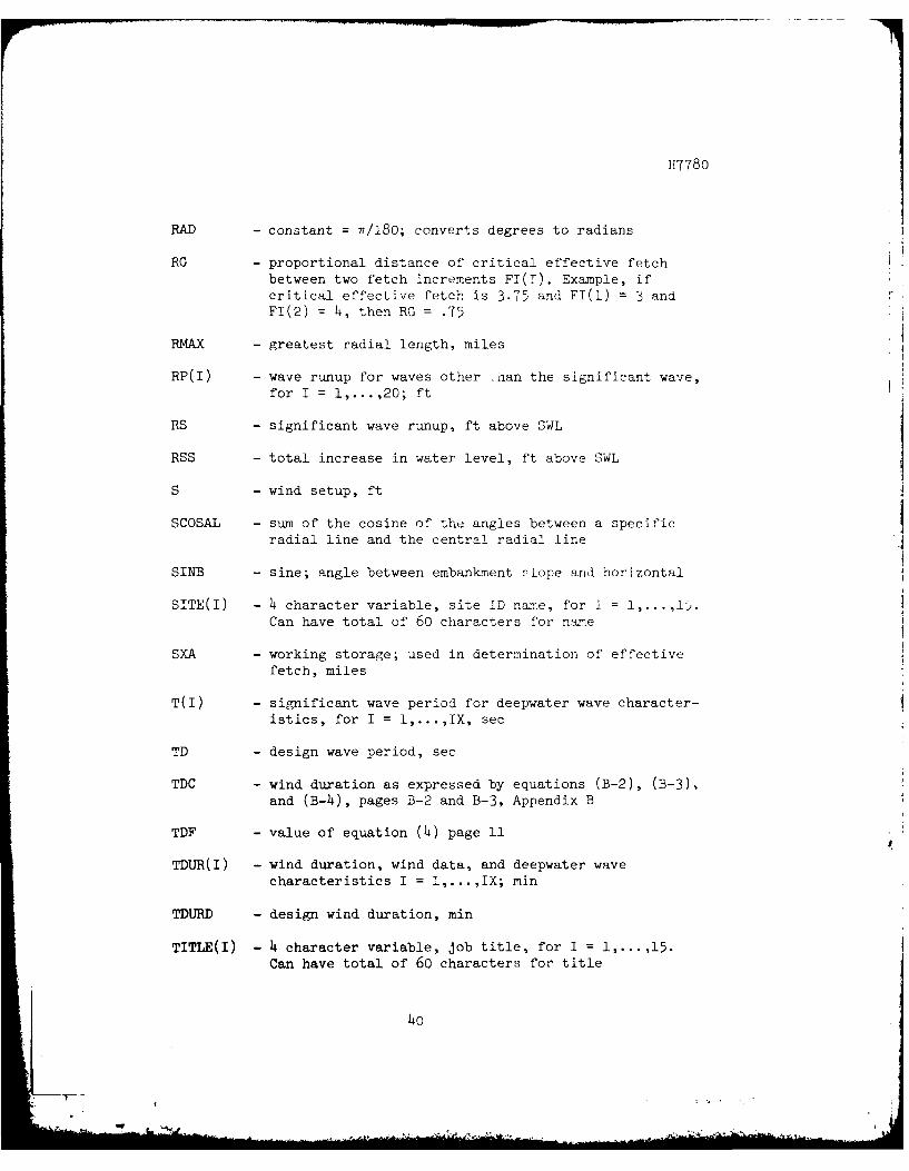
RAD - constant = n/280; converts degrees to radians
RG - proportional distance of critical effective fetch
between two fetch increments FI(I). Example, ifcritical effective fetch is 3.75 and FI(l) = 3 andFI(2) = 4, then RG = .75
RMAX - greatest radial length, miles
RP(I) - wave runup for waves other nan the significant wave,
for I = 1,...,20; ft
RS - significant wave runup, ft above SWL
RSS - total increase in water level, ft above SWL
S - wind setup, ft
SCOSAL - sum of the cosine of the angles between a specificradial line and the central radial line
SINB - sine; angle between embankment slope and horizontal
SITE(I) - 4 character variable, site ID name, for I = 1,...,15.Can have total of 60 characters for name
SXA - working storage; used in determination of effective
fetch, miles
T(I) - significant wave period for deepwater wave character-istics, for I = 1,...,IX, sec
TD - design wave period, sec
TDC - wind duration as expressed by equations (B-2), (B-3),
and (B-4), pages B-2 and B-3, Appendix B
TDF - value of equation (4) page 11
TDUR(I) - wind duration, wind data, and deepwater wavecharacteristics I = 1,...,IX; min
TDURD - design wind duration, min
TITLE(I) - 4 character variable, job title, for I = 1,...,15.Can have total of 60 characters for title
4o

H7780
U - wind speed, mph
UD - design wind speed, mph
UF(I) - wind speed overwater for wind data and deepwaterwave characteristics, I=l,...,IX; mph
UL - input overland wind speed, mph
US - wind speed, fps
Ul - maximum I minute wind speed, mph
U2 - input maximum 1 minute wind speed, mph
U30 - 30 minute wind speed, mph
U360 - 360 minute wind speed, mph
U60 - maximum 60 minute wind speed, mph
u61 - input maximum 60 minute wind speed, mph
WR(I) - wind factors corresponding to fetch increments FI(I),I = 1,....,7
I WR I WR I WR1 1 2 1.08 3 1.134 1.21 5 1.26 6 1.287 1.30
X(I) - radial lengths, miles
XA - working storage in determination of effective fetch,miles
ZA - working storage used in determination of wave runup;
/H1/2equal to the expression H (1.58 - 2.35 tan 0) ofequation (11) page 14 \sI
ZB - working storage used in determination of wave runup;equal to the expression .092 cot e - .26 of equa-tion (11) page 14
41

H7780
ZC - working storage used in determination of wave runup;equal to the expression sin e (5.95 tan e + 1.5) ofequation (10) page 14
ZE - value of equation (11) page 14
c. Subroutine H77801: Variables are as explained in subroutine
H7780, except
LQZ - equal 1, execute input cues and reads; = 2, call RERUNand enter only desired inputs
JKL - direct return from RERUN to desired input read
KKK - total number of inputs passed to RERUN
d. Subroutine H7780W: Variables are as explained in subroutine
H7780 except
NLIN - number of lines in data file; maximum number of 13
LINE(I) - line number in data file; start at 100 and incrementedby 2 for I = 2,...,NLIN
M8 - number of 8 variable lines required for writing radial
length
MR - number of radial lengths left after M8 lines written
e. Subroutine H7780H: This subroutine writes the header informa-
tion and tabulated output to the output file for graphics and/or other
use. The header information may be seen in formats 20070 and 20100,
line numbers 20070-20080 and 20100-20140 of the source listing, page 68.
Variables are as explained in subroutine H7780 except
AFILE - 10 character variable used in attaching existing inputdata file
LINE(I) - line number in data file; start at 100 and incrementby 2 for I = 1,...,IX; maximum number 50
42

H7780
10. EXAMPLE CASE: The example problems presented were taken from those
given in ETL 1110-2-221 and ETL 1110-2-8 (references I and 10) for
Dension and McGee Bend Reservoirs. Fetch, average depth, and slope
inclination data used correspond to the values given in those ref-
erences. Wind data used are based on the overland maximum one-minute
and sixty-minute wind speeds obtained from the appropriate figures in
reference 1. For demonstration purposes only, the depths at the toe of
the structures and type of embankment slopes were arbitrarily selected.
Examples 1 and 2 are for smooth embankment slopes and example 3 is a run
with different data files using the RERUN option for turfed slopes,
small stepped slopes, and riprapped slopes.
Example 1 Runs program with no permanent data file
PIT, VEQLIP/COPPC/H77dd,p
43
ij

H7780
INPUT H7780 - WAVE RUNUP AND WIND SETUP,COMPUTATIONAL MODEL
PERM DATA FILE;Y OR N=N
WE WILL HELP YOU SETUP YOUR DATAFILE. ENTER FILE NAME=DH7780AA-ENTER JOB TITLE < OR = 60 CHARACTERS=DENSION RESERVOIRAB-ENTER SITE ID < OR = 60 CHARACTERS=STATION AAC-ENTER THE NUMBER OF RADIALS USED TO DETERMINE EFFECTIVEFETCH DISTANCE;A MINIMUM OF 15 RADIALS IS REQUIRED:15AD-ENTER THE 15 RADIAL LENGTHS IN MILES,SPEARATE BY COMMAS=2.23,2.21,2.92,3.2,5.05,4.58,5.45,8.02,7.86,7.53,2.11,1.71,1.24=1.25,1.22AE-USE DESIGN OVERLAND WIND SPEED OR 1 MIN AND 60 MIN WIND SPEEDAS IN ETL 1110-2-221;0,DESIGN;I,1 MIN AND 60 MIN=1AF-ENTER 1 MIN AND 60 MIN WIND SPEEDSMPH=65,45AG-ENTER FACTOR FOR DESIGN WAVE;O,DESIGN WAVE IS SIGNIFICANTWAVE;1,DESIGN WAVE IS OTHER RELATED WAVE=1AH-ARE DEEP WATER WAVE CHARACTERISTICS TO BE PRINTED;O,NO PRINT;1,PRINT=1AI-ENTER WATER DEPTH AT TOE OF STRUCTURE,FT=20AJ-ENTER AVERAGE WATER DEPTH ALONG WIND FETCH,FT=50AK-ENTER COTANGENT OF ANGLE BETWEEN EMBANKMENT SLOPE AND HORIZONTAL=2.5AL-ENTER FACTOR FOR REDUCING WAVE RUNUP ON SMOOTH SLOPE WHERE SLOPE 1ZSLIGHTLY ROUGHER THAN SMOOTH=1AM-ENTER SLOPE COVER ;-1,RIPRAP;O,SMOOTH;1,OTHER=0
AN-SAVE TABULATED OUTPUT FOR GRAPHICS OR OTHER USE=Y
FILE NAME=PH7780CHANGE ANY DATA BEFORE RUN,Y OR N=N
OUTPUT H7780 - WAVE RUNUP AND WIND SETUP,COMPUTATIONAL MODEL
DENSION RESERVOIRSTATION A
BASIC DATA
DEPTH AT TOE OF EMBANKMENT = 20.00 FTAVERAGE WATER DEPTH 50.00 FTEMBANKMENT SLOPE = 2.50H:1VSMOuTH SLOPE MODIFICATION FACTOR = 1.00ONE MINUTE WIND SPEED = 65.00 MPHSIXTY MINUTE WIND SPEED 45.00 MPH
RADIALS CORRESPONDING TO CRITICAL EFFECTIVE FETCH IN MILES
2.23 2.21 2.92 3.20 5.05 4.58 5.45 8.027.86 7.53 2.11 1.71 1.24 1.25 1.22
44

H778o
COMPUTATIONAL RESULTS
EFFECTIVE WAVE FETCH 3.75 MILES
TRANSITIONAL WATER WAVE CONDITIONS USED FOR PRESENT PROBLEM
EMBANKMENT SLOPE - SMOOTH
DESIGN WIND SPEED = 63.00 MPHDESIGN WIND DURATION 36.34 MINDESIGN WAVE HEIGHT = 5.29 FTDESIGN WAVE PERIOD = 4.47 SECDESIGN DEEP WATER WAVE LENGTH = 102.80 FTFETCH FOR WIND SETUP = 7.50 MILESWIND SETUP = 0.42 FTSIGNIFICANT WAVE RUNUP = 9.86 FT ABOVE SWITOTAL INCREASE IN WATER LEVEL 10.29 FT ABOVE SWL
WIND DATA AND DEEP WATER WAVE CHARACTERISTICS
OVER WATER WIND SIGNIFICANT SIGNIFICANTWIND SPEED DURATION WAVE HEIGHT WAVE PERIOD
(MPH) (MIN) (FT) (SEC)
50.00 40.97 4.38 4.2751.00 40.55 4.48 4.3252.00 40.15 4.58 4.3653.00 39.75 4.68 4.4054.00 39.37 4.79 4.4555.00 39.00 4.89 4.4956.00 38.63 4.99 4.5357.00 38.28 5.10 4.5758.00 37.94 5.20 4.6159.00 37.60 5.31 4.6560.00 37.27 5.41 4.6961.00 36.96 5.52 4.7462.00 36.65 5.62 4.7863.00 36.34 5.73 4.8164.00 36.05 5.83 4.8565.00 35.76 5.94 4.8966.00 35.48 6.05 4.9367.00 35.20 6.15 4.9768.00 34.93 6.26 5.0169.00 34.67 6.37 5.0570.00 34.41 6.47 5.0871.00 34.16 6.58 5.1272.00 33.92 6.69 5.1673.00 53.68 6.80 5.1974.00 33.q4 6.91 5.2375.00 33.21 7.01 5.2776.00 32.98 1.12 5.3077.00 32.76 7.23 5.3478.00 32.54 7.34 5.3779.00 32.33 7.45 5.4180.00 32.12 7.56 5.4481.00 31.91 7.67 5.48
45
H7780
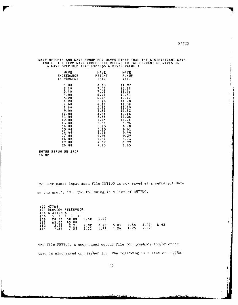
WAVE HEIGHTS AND WAVE RUNUP FOR WAVES OTHER THAN THE SIGINIFICANT WAVE(NOTE- THE TERM WAVE EXCEEDENCE REFERS TO THE PERCENT OF WAVES IN
A WAVE SPECTRUM THAT EXCEEDS A GIVEN VALUE.)
WAVE WAVE WAVEEXCEEDANCE HEIGHT RUNUPIN PERCENT (PT) (FT)
1.00 8.03 14.972.00 7.40 13.803.00 7.01 13.064.00 6.71 12.515.00 6.48 12.076.00 6.28 11.707.00 6.10 11.388.00 5.95 11.099.00 5.81 10.82
10.00 5.68 10.5811.00 5.56 10.3612.00 5.45 10.1613.00 5.34 9.9614.00 5.25 9.7815.00 5.15 9.6116.00 5.06 9.4417.00 4.98 9.2918.00 4.90 9.1319.00 4.82 8.9920.00 4.75 8.85
ENTER RERUN OR STOP=STOP
The user named input data file DH7780 is now saved as a permanent data
on the user's ID. The following is a list of DH7780.
100 H7780102 DENSION RESERVOIR104 STATION A106 15 0 1 1 1108 20.00 50.00 2.50 1.00110 65.00 45.00112 2.23 2.21 2.92 3.20 5.05 4.58 5.45 8.02
114 7.86 7.53 2.11 1.71 1.24 1.25 1.22
The file PH7780, a user named output file for graphics and/or other
use, is also saved on his/her ID. The following is a list of PH7780.
46
H778r0
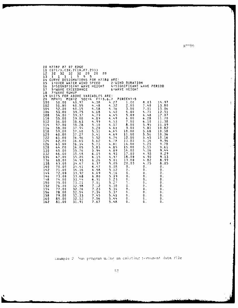
10 H778C 07 07 EDGE11 (07(/),(3X,7(1X,F7.2)))12 32 32 32 32 20 20 2013 1 1 1 1 5 5 514 CURVE DESIGNATIONS FOR H7780 ARE:15 1=OVER WATER WIND SPEED 2:WIND DURATION16 3=SIGNIFICANT WAVE HEIGHT 4=SIGNIFICANT WAVE PERIOD17 5=WAVE EXCEEDANCE 6:WAVE HEIGHT18 7=WAVE RUNUP19 UNITS FOR ABOVE VARIABLES ARE:20 MPH=I MIN=2 SEC=4 FT=3,6,7 PERCENT=5100 50.00 40.97 4.38 4.27 1.00 8.03 14.97102 51.00 40.55 4.48 4 .32 2. 00 7.40 13.80104 52.00 40.15 4.58 4.36 3.00 7.01 13.06106 53.00 39.75 4.68 4.40 4.00 6.71 12.51108 54.00 39.37 4.79 4.45 5.00 6.48 12.07110 55.00 39.00 4.89 4.49 6.00 6.28 11.70112 56.00 38.63 4.99 4.53 7.00 6.10 11.38114 57.00 38.28 5.10 4.57 8.00 5.95 11.09116 58.00 37.94 5.20 4.61 9.00 5.81 10.82118 59.00 37.60 5.31 4.65 10.00 5.68 10.58120 60.00 37.27 5.41 4.69 11.00 5.56 10.36122 61.00 36.96 5.52 4.74 12.00 5.45 10.16124 62.00 36.65 5.62 4.78 13.00 5.34 9.96126 63.00 36.34 5.73 4.81 14.00 5.25 9.78128 64.00 36.05 5.83 4 .85 15 .00 5.15 9.61130 65.00 35.76 5.94 4.89 16.00 5.06 9.44132 66.00 35.48 6.05 4.93 17.00 4.93 9.29134 67.00 35.20 6.15 4.97 18.00 4.90 9.13136 68.00 34.93 6.26 5.01 19.00 4.82 8.99138 69.00 34.67 6.37 5.05 20.00 4.75 8.85140 70.00 34.41 6.47 5.08 0. 0. 0.142 71.00 34.16 6.58 5.12 0. 0. 0.144 72.00 33.92 6.69 5.16 0. 0. 0.146 73.00 33.68 6.80 5.19 0. 0. 0.!48 74.00 33.44 6.91 5.23 0. 0. 0.150 75.00 33.21 7.01 5.27 0. 0. 0.152 76.00 32.98 7.12 5 .30 0. 0. 0.154 77.00 32.76 7.23 5.34 0. 0. 0.156 78.00 32.54 7.34 5.37 0. 0. 0.158 79.00 32.33 7.45 5.41 0. 0. 0.160 80.00 32.12 7.56 5.44 0. 0. 0.162 81.00 31.91 7.67 5.48 0. 0. 0.
IExamp] e 2 Run program u,;iri an cxi i,. I pf.rm:n,.r t data fi.le
) 7

1177cC
INPUT H7780 - WAVE RUNUP AND WIND SETUP,COMPUTATIONAL MODEL
PERM DATA FILE;Y OR N=y
DATAFILE NAME=DH77801 CHANGE ANY DATA BEFORE RUN,Y OR N=N
OUTPUT H7780 - WAVE RUNUP AND WIND SETUP,COMPUTATIONAL MODEL
MCGEE BEND RESERVOIRSTATION A
BASIC DATA
DEPTH AT TOE OF EMBANKMENT = 20.00 FTAVERAGE WATER DEPTH 73.00 FTEMBANKMlENT SLOPE = 2.50H:IVSMOOTH SLOPE MODIFICATION FACTOR 1.00ONE MINUTE WIND SPEED = 55.00 MPHSIXTY MINUTE WIND SPEED 50.00 MPH
RADIALS CORRESPONDING TO CRITICAL EFFECTIVE FETCH IN MILES
1.33 2.70 2.89 3.22 6.49 12.64 16.95 16.7112.31 11.74 6.39 5.87 5.59 3.46 3.41
COMPUTATIONAL RESULTS
EFFECTIVE WAVE FETCH 7.49 MILES
TRANSITIONAL WATER WAVE CONDITIONS USED FOR PRESENT PROBLEM
EMBANKMENT SLOPE - SMOOTH
DESIGN WIND SPEED = 64.00 MPHDESIGN WIND DURATION 61.01 MINDESIGN WAVE HEIGHT = 7.18 FTDESIGN WAVE PERIOD = 5.31 SECDESIGN DEEP WATER WAVE LENGTH = 144.43 FTFETCH FOR WIND SETUP = 14.98 MILESWIND SETUP = 0.60 FTSIGNIFICANT WAVE RUNUP = 14.18 FT ABOVE SWtTOTAL INCREASE IN WATER LEVEL = 14.78 FT ABOVE SWL
4R

H7780
WIND DATA AND DEEP WATER WAVE CHARACTERISTICS
OVER WATER WIND SIGNIFICANT SIGNIFICANTWIND SPEED DURATION WAVE HEIGHT WAVE PERIOD
(MP1H) (MIN) (FT) (SEC)
57.00 64.80 6.81 5.4058.00 64.22 6.95 5.4459.00 63.65 7.09 5.4960.00 63.09 7.23 5.5461.00 62.55 7.37 5.5962.00 62.03 7.51 5.6463.00 61.51 7.65 5.6964.00 61.01 7.79 5.7365.00 60.52 7.93 5.7866.00 60.04 8.08 5.8367.00 59.57 8.22 5.8768.00 59.11 8.36 5.9269.00 58.67 8.51 5.9670.00 58.23 8.65 6.01
WAVE HEIGHTS AND WAVE RUNUP FOR WAVES OTHER THAN THE SIGINIFICANT WAVE(NOTE- THE TERM WAVE EXCEEDENCE REFERS TO THE PERCENT OF WAVES IN
A WAVE SPECTRUM THAT EXCEEDS A GIVEN VALUE.)
WAVE WAVE WAVEEXCEEDANCE HEIGHT RUNUPIN PERCENT (FT) (FT)
1.00 10.90 21.522.00 10.05 19.843.00 9.51 18.784.00 9.11 17.995.00 8.79 17.366.00 8.52 16.827.00 8.28 16.358.00 8.07 15.949.00 7.88 15.5610.00 7.71 15.2211.00 7.55 14.9012.00 7.40 14.6013.00 7.25 14.3214.00 7.12 14.0615.00 7.00 13.8116.00 6.88 13.5817.00 6.76 13.3518.00 6.65 13.1319.00 6.54 12.9220.00 6.44 12.72
ENTER RERUN OR STOP=STOP
149

H7780
The following is a -11 t of the per" e iput d't f I H77801 used
in example 2.
100 H7780102 MCGEE BEND RESERVOIR104 STATION A106 15 0 1 1 1108 20.00 73.00 2.50 1.00110 55.00 50.00112 1.33 2.70 2.89 3.22 6.49 12.64 16.95 16.71114 12.31 11.74 6.39 5.87 5.59 3.46 3.41
Ixample 3 Run program using different existing iLtt files and the
rerun option.
INPUT H7780 - WAVE RUNUP AND WIND SETUP,COMPUTATIONAL MODEL
PERM DATA FILE;Y OR N=y
DATAFILE NAME=DH7780CHANGE ANY DATA BEFORE RUN,Y OR N=y
RERUN OPTION PERMITS YOU TO CHANGE ANY OR ALL INPUT VARIABLES.AT >>>= QUE TYPE IN THE TWO LETTERS(AA,AB,ETC.) CORRESPOeIDINGTO THE VARIABLES YOU WISH TO CHANGE. THEN AT NEXT = QUE, ENTERTHE NUMERICAL VALUE. TO TERMINATE DATA ENTRY, TYPE A CARRIAGERETURN AT >>>z QUE.
=AGAG-ENTER FACTOR FOR DESIGN WAVE;C,OESIGN WAVE IS SIGNIFICANTWAVE;I,DESIGN WAVE IS OTHER RELATED WAVE
=AHAH-ARE DEEP WATER WAVE CHARACTERISTICS TO BE PRINTED;O,NO PRINT;1,PRINT:0
:ALAL-ENTER FACTOR FOR REDUCING WAVE RUNUP ON SMOOTH SLOPE WHERE SLOPE ISSLIGHTLY ROUGHER THAN SMOOTH.9
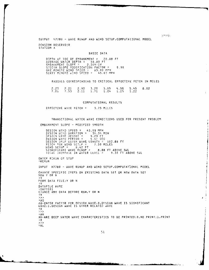
OUTPUT H7780 - WAVE RUNUP AND WIND SETUP,COMPUTATIONAL MODEL
DENSION RESERVOIRSTATION A
BASIC DATA
DEPTH AT TOE OF EMBANKMENT = 20.00 FTAVERAGE WATER DEPTH = 50.00 FTErBAGKMENT SLOPE 2.50H:1VS:1OOTH SLOPE NODIFICATION FACTOR 0.90OhE MINUTE WIND SPEED 65.00 MPHSIXTY MINUTE W IND SPEED z 45.00 MPH
RADIALS CORRESPONDING TO CRITICAL EFFECTIVE FETCH IN MILES
2.23 2.21 2.92 3.20 5.05 4.58 5.45 8.027.86 7.53 2.11 1.71 1.24 1.25 1.22
COMPUTATIONAL RESULTS
EFFECTIVE WAVE FETCH 3.75 MILES
TRANSITIONAL WATER WAVE CONDITIONS USED FOR PRESENT PROBLEM
EMBANKMENT SLOPE - MODIFIED SMOOTH
DESIGN WIND SPEED 63.00 MPHDESIGN WI;D DURATION 2 36.34 MINDESIGN WAVE HEIGHT = 5.29 FTDESIGN WAVE PERIOD = 4.47 SECDESIGN DEEP WATER WAVE LENGTH = 102.80 FTFETCH FOR WIND SETUP = 7.50 MILESWIND SETUP = 0.42 FTSIGNIFICANT WAVE RUNUP 8.88 FT ABOVE SWLTOTAL !NIREASE IN WATER LEVEL 9.30 FT ABOVE SWL
ENTER RERUN OR STOP=RERUN
INPUT H7780 - WAVE RUNUP AND WIND SETUP,COMPUTATiONAL MODEL
CHANGE SPECIFIC ITEMS ON EXISTING DATA SET OR NEW DATA SETNEW Y OR N
PERM DATA FILE;Y OR NZy
DATAFILE NAMEzDH17901CHANGE ANY DATA BEFORE RUN,Y OR N=y>>>
=AGAG-ENTER FACTOR FOR DESIGN WAVE;O,DFSIGN WAVE IS SIGNIFICANTWAVE;1,DESIGN WAVE IS OTHER RELATED WAVE-0
A HAH-ARE DEEP WATER WAVE CHARACTERISTICS TO BE PRINTED;O,NO PRINT;1,PRINT:0
=AL
5I

H7780
AL-ENTER FACTOR FOR REDUCING WAVE RUNUP ON SMOOTH SLOPE WHERE SLOPE ISSLIGHTLY ROUGHER THAN SMOOTH=.9
OUTPUT H7780 - WAVE RUNUP AND WIND SETUP,COMPUTATIONAL MODEL
MCGEE BEND RESERVOIRSTATION A
BASIC DATA
DEPTH AT TOE OF EMBANKMENT 20.00 FTAVERAGE WATER DEPTH 73.00 FTEMBANKMENT SLOPE = 2.50H:IVSMOOTH SLOPE MODIFICATION FACTOR 0.90ONE MINUTE WIND SPEED = 55.00 MPHSIXTY MINUTE WIND SPEED = 50.00 MPH
RADIALS CORRESPONDING TO CRITICAL EFFECTIVE FETCH IN MILES
1.33 2.70 2.89 3.22 6.49 12.64 16.95 16.7112.31 11.74 6.39 5.87 5.59 3.46 3.41
COMPUTATIONAL RESULTS
EFFECTIVE WAVE FETCH = 7.49 MILES
TRANSITIONAL WATER WAVE CONDITIONS USED FOR PRESENT PROBLEM
EMBANKMENT SLOPE - MODIFIED SMOOTH
DESIGN WIND SPEED = 64.00 MPHDESIGN WIND DURATION 61.01 MINDESIGN WAVE HEIGHT = 7.18 FTDESIGN WAVE PERIOD = 5.31 SECDESIGN DEEP WATER WAVE LENGTH = 144.43 FTFETCH FOR WIND SETUP = 14.98 MILESWIND SETUP = 0.60 FTSIGNIFICANT WAVE RUNUP 12.76 FT ABOVE SWLTOTAL INCREASE IN WATER LEVEL 13.36 FT ABOVE 5WL
ENTER RERUN OR STOP=RERUN
INPUT H7780 - WAVE RUNUP AND WIND SETUP,COMPUTATIONAL MODEL
CHANGE SPECIFIC ITEMS ON EXISTING DATA SET OR NEW DATA SETNEW Y OR N= N
=ALAL-ENTER FACTOR FOR REDUCING WAVE RUNUP ON SMOOTH SLOPE WHERE SLOPE ISSLIGHTLY ROUGHER THAN SMOOTH=.75
52
H7780
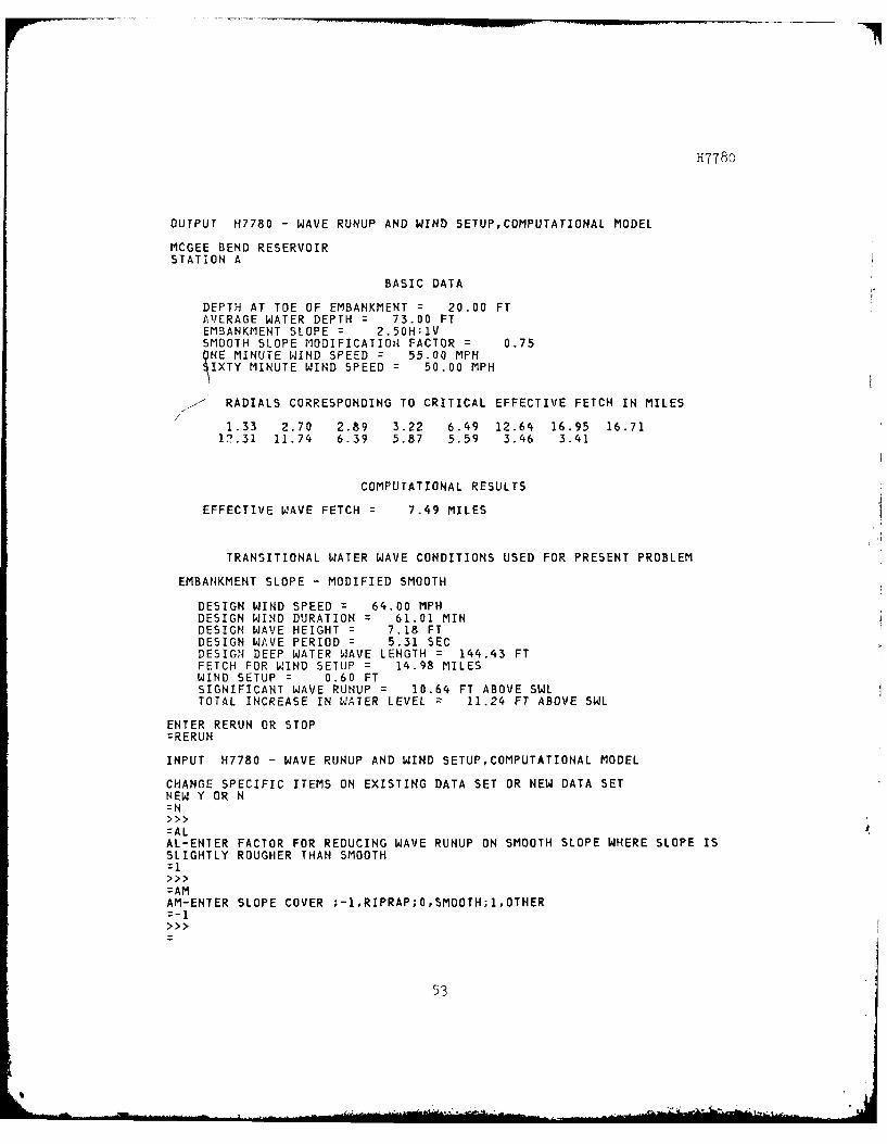
OUTPUT H7780 - WAVE RUNUP AND WIND SETUP,COMPUTATIONAL MODEL
MCGEE BEND RESERVOIR
STATION A
BASIC DATA
DEPTH AT TOE OF EMBANKMENT 20.00 FTAVERAGE WATER DEPTH 73.00 FTEMBANKMENT SLOPE = 2.50H:lVSMOOTH SLOPE MODIFICATION FACTOR 0.75QNE MINUTE WIND SPEED = 55.00 MPHIXTY MINUTE WIND SPEED 50.00 MPH
RADIALS CORRESPONDING TO CRITICAL EFFECTIVE FETCH IN MILES/
1.33 2.70 2.89 3.22 6.49 12.64 16.95 16.7112.31 11.74 6.39 5.87 5.59 3.46 3.41
COMPUTATIONAL RESULTS
EFFECTIVE WAVE FETCH 7.49 MILES
TRANSITIONAL WATER WAVE CONDITIONS USED FOR PRESENT PROBLEM
EMBANKMENT SLOPE - MODIFIED SMOOTH
DESIGN WIND SPEED 64.00 MPHDESIGN WIND DURATION : 61.01 MINDESIGN WAVE HEIGHT = 7.18 FTDESIGN WAVE PERIOD = 5.31 SECDESIGN DEEP WATER WAVE LENGTH z 144.43 FTFETCH FOR WIND SETUP = 14.98 MILESWIND SETUP = 0.60 FTSIGNIFICANT WAVE RUNUP 10.64 FT ABOVE SWLTOTAL INCREASE IN WATER LEVEL 11.24 FT ABOVE SWL
ENTER RERUN OR STOP=RERUN
INPUT H7780 - WAVE RUNUP AND WIND SETUP,COMPUTATIONAL MODEL
CHANGE SPECIFIC ITEMS ON EXISTING DATA SET OR NEW DATA SETNEW Y OR N=N>>>
=ALAL-ENTER FACTOR FOR REDUCING WAVE RUNUP ON SMOOTH SLOPE WHERE SLOPE ISSLIGHTLY ROUGHER THAN SMOOTH=i
=AMAM-ENTER SLOPE COVER ;-I,RIPRAP;O,SMOOTH;1,OTHER=-I
53

H7780
OUTPUT H7780 - WAVE RUNUP AND WIND SETUP,COMPUTATIONAL MODEL
MCGEE BEND RESERVOIRSTATION A
BASIC DATA
DEPTH AT TOE OF EMBANKMENT = 20.00 FTAVERAGE WATER DEPTH 73.00 FTEMBANKMENT SLOPE = 2.50H:IVSMOOTH SLOPE MODIFICATION FACTOR 1.00ONE MINUTE WIND SPEED = 55.00 MPHSIXTY MINUTE WIND SPEED = 50.00 MPH
RADIALS CORRESPONDING TO CRITICAL EFFECTIVE FETCH IN MILES
1.33 2.70 2.89 3.22 6.49 12.64 16.95 16.7112.31 11.74 6.39 5.87 5.59 3.46 3.41
COMPUTATIONAL RESULTS
EFFECTIVE WAVE FETCH = 7.49 MILES
TRANSITIONAL WATER WAVE CONDITIONS USED FOR PRESENT PROBLEM
EMBANKMENT SLOPE - RIPRAP
DESIGN WIND SPEED = 64.00 MPHDESIGN WIND DURATION 61.01 MINDESIGN WAVE HEIGHT = 7.18 FTDESIGN WAVE PERIOD = 5.31 SECDESIGN DEEP WATER WAVE LENGTH = 144.43 FTFETCH FOR WIND SETUP = 14.98 MILESWIND SETUP = 0.60 FTSIGNIFICANT WAVE RUNUP = 7.50 FT ABOVE SWLTOTAL INCREASE IN WATER LEVEL 8.10 FT ABOVE SWL
ENTER RERUN OR STOP=RERUN
INPUT H7780 - WAVE RUNUP AND WIND SETUPCOMPUTATIONAL MODEL
CHANGE SPECIFIC ITEMS ON EXISTING DATA SET OR NEW DATA SETNEW Y OR N=Y
PERM DATA FILE;Y OR N=Y
DATAFILE NAME=DH7780CHANGE ANY DATA BEFORE RUN,Y OR N=Y
=ALAL-ENTER FACTOR FOR REDUCING WAVE RUNUP ON SMOOTH SLOPE WHERE SLOPE ISSLIGHTLY ROUGHER THAN SMOOTH=.75
54>>

H7780
OUTPUT H7780 - WAVE RUNUP AND WIND SETUP,COMPUTATIONAL MODEL
DENSION RESERVOIRSTATION A
BASIC DATA
DEPTH AT TOE OF EMBANKMENT = 20.00 FTAVERAGE WATER DEPTH 50.00 FTEMBANKMENT SLOPE = 2.50H:lVSMOOTH SLOPE MODIFICATION FACTOR 0.75ONE MINUTE WIND SPEED = 65.00 MPHSIXTY MINUTE WIND SPEED 45.00 MPH
RADIALS CORRESPONDING TO CRITICAL EFFECTIVE FETCH IN MILES
2.23 2.21 2.92 3.20 5.05 4.58 5.45 8.027.86 7.53 2.11 1.71 1.24 1.25 1.22
COMPUTATIONAL RESULTS
EFFECTIVE WAVE FETCH = 3.75 MILES
TRANSITIONAL WATER WAVE CONDITIONS USED FOR PRESENT PROBLEM
EMBANKMENT SLOPE - MODIFIED SMOOTH
DESIGN WIND SPEED = 63.00 MPHDESIGN WIND DURATION : 36.34 MINDESIGN WAVE HEIGHT = 5.29 FTDESIGN WAVE PERIOD = 4.47 SECDESIGN DEEP WATER WAVE LENGTH = 102.80 FTFETCH FOR WIND SETUP = 7.50 MILESWIND SETUP = 0.42 FTSIGNIFICANT WAVE RUNUP 7.40 FT ABOVE SWLTOTAL INCREASE IN WATER LEVEL 7.82 FT ABOVE SWL
ENTER RERUN OR STOP=RERUN
INPUT H7780 - WAVE RUNUP AND WIND SETUP,COMPUTATIONAL MODEL
CHANGE SPECIFIC ITEMS ON EXISTING DATA SET OR NEW DATA SETNEW Y OR H=N
=AL
AL-ENTER FACTOR FOR REDUCING WAVE RUNUP ON SMOOTH SLOPE WHERE SLOPE ISSLIGHTLY ROUGHER THAN SMOOTH=1
=AMAM-ENTER SLOPE COVER ;-1,RIPRAP;O,SMOOTH;1,OTHER
55
SB

H7780
OUTPUT H7780 - WAVE RUNUP AND WIND SETUP,COMPUTATIONAL MODEL
DENSION RESERVOIRSTATION A
BASIC DATA
DEPTH AT TOE OF EMBANKMENT = 20.00 FTAVERAGE WATER DEPTH 50.00 FTEMBANKMENT SLOPE = 2.50H:lVSMOOTH SLOPE MODIFICATION FACTOR 1.00ONE MINUTE WIND SPEED = 65.00 MPHSIXTY MINUTE WIND SPEED 45.00 MPH
RADIALS CORRESPONDING TO CRITICAL EFFECTIVE FETCH IN MILES
2.23 2.21 2.92 3.20 5.05 4.58 5.45 8.027.86 7.53 2.11 1.71 1.24 1.25 1.22
COMPUTATIONAL RESULTS
EFFECTIVE WAVE FETCH 3 3.75 MILES
TRANSITIONAL WATER WAVE CONDITIONS USED FOR PRESENT PROBLEM
EMBANKMENT SLOPE - RIPRAP
DESIGN WIND SPEED 63.00 MPHDESIGN WIND DURATION 36.34 MINDESIGN WAVE HEIGHT = 5.29 FTDESIGN WAVE PERIOD 4.27 SECDESIGN DEEP WATER WAVE LENGTH = 102.80 FTFESCH FOR WIND SETUP 7.50 MILESWIND SETUP = 0.42 FTSIGNIFICANT WAVE RUNUP 5.6 FT ABOVE SWL
TOTAL INCREASE IN WATER LEVEL 5.89 FT ABOVE SWL
ENTER RERUN OR STOP=STOP
The following is a list of the permanent input data files DH7780 and
DH77801 as changed by the last run of each file.
56

H7780
DH7780:
100 H7780102 MCGEE BEND RESERVOIR104 STATION A106 15 -1 1 0 0108 20.00 73.00 2.50 1.00
110 55.00 50.00112 1.33 2.70 2.89 3.22 6.49 12.64 16.95 16.71
114 12.31 11.74 6.39 5.87 5.59 3.46 3.41
DH77801
120' ,Z7730IC2 -'! -- )-I rcrv,1 T"
io5 15 -1 0 P 5
113 5.2Z 45.0.13112 2.23 2.21 2.92 3.2Z 5.05 4.53 5.45 3.02
114 7.36 7.53 2.11 1.71 1.24 1.25 1.22
57
57!

H7780
REF: ER 1110-1-10 -ENGINEERING AND DESIGN -Engineering and ComputerProgram Library Standards and Documentation, Appendix C
PART III: FILE DOCUMENTATION
1. REVISION LOG: Program coding revised June 78 to accommodate the
CORPS time-share features.
2. TITLE: H7780 - Wave Runup and Wind Setup - Computational Model
3. PROGRAM SOURCE LISTINGS: See pages 59-68
4. NUMERICAL AND LOGICAL ANALYSIS: Wave runup and wind setup are
solved by direct solution of algebraic equations except for the transi-
tional depth wave length which is solved via an interactive technique.
5. SUBROUTINES NOT DOCUMENTED IN ABSTRACT: None
6. MISCELLANEOUS: The program is part of the CORPS computer system.
CORPS is an acronym standing for Conversationally Oriented Real-Time
Program-Generating System. The program is now operational on the WES
G635, Vicksburg, MS; HIS 66/8o, Macon, GA; and Boeing CDC, Seattle, WA.
The source listing on page 59 contains the first line run command and
brief for H7780. This first line run command runs the binary H7780B of
the source listing on pages 60-68 (FORTRAN source of H7780) and attaches
the WESLIB routines RERUN, HACCT, and TACHFILE.
58
Mor..w . '... _ 4._
H7780
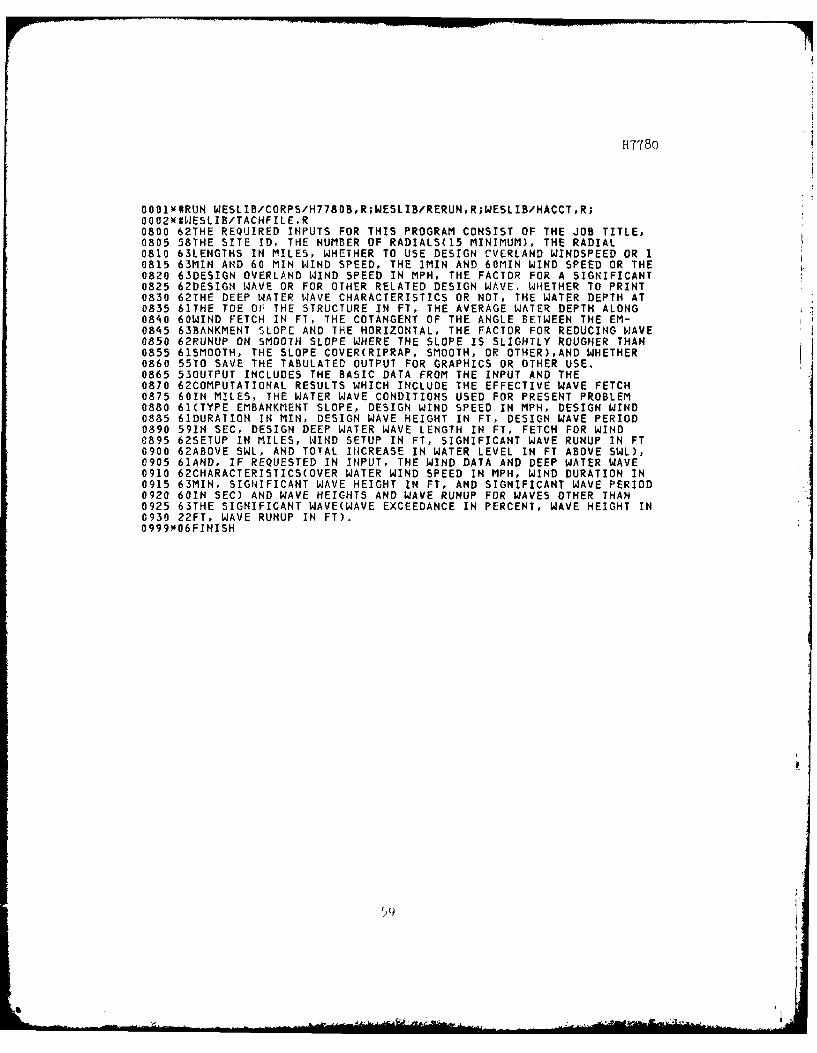
O001X#RUN WESLIB/CORPS/H7780B,R;WESLIB/RERUN,R;WESLIB/HACCT,R;0002x#WESLIB/TACHFILE,R0800 62THE REQUIRED INPUTS FOR THIS PROGRAM CONSIST OF THE JOB TITLE,0805 58THE SITE ID, THE NUMBER OF RADIALS(15 MINIMUM), THE RADIAL0810 63LENGTHS IN MILES, WHETHER TO USE DESIGN CVERLAND WINDSPEED OR I0815 63MIN AND 60 MIN WIND SPEED, THE iMIN AND 60MIN WIND SPEED OR THE0820 63DESIGN OVERLAND WIND SPEED IN MPH, THE FACTOR FOR A SIGNIFICANT0825 62DESIGN WAVE OR FOR OTHER RELATED DESIGN WAVE. WHETHER TO PRINT0830 62THE DEEP WATER WAVE CHARACTERISTICS OR NOT, THE WATER DEPTH AT0835 61THE TOE OF THE STRUCTURE IN FT, THE AVERAGE WATER DEPTH ALONG0840 60WIND FETCH IN FT, THE COTANGENT OF THE ANGLE BETWEEN THE EM-0845 63BANKMENT SLOPE AND THE HORIZONTAL, THE FACTOR FOR REDUCING WAVE0850 62RUNUP ON SMOOTH SLOPE WHERE THE SLOPE IS SLIGHTLY ROUGHER THAN0855 61SMOOTH, THE SLOPE COVER(RIPRAP, SMOOTH, OR OTHER),AND WHETHER0860 55T0 SAVE THE TABULATED OUTPUT FOR GRAPHICS OR OTHER USE.0865 53OUTPUT INCLUDES THE BASIC DATA FROM THE INPUT AND THE0870 62COMPUTATIONAL RESULTS WHICH INCLUDE THE EFFECTIVE WAVE FETCH0875 60IN MILES, THE WATER WAVE CONDITIONS USED FOR PRESENT PROBLEM0880 61(TYPE EMBANKMENT SLOPE, DESIGN WIND SPEED IN MPH, DESIGN WIND0885 61DURATION IN MIN, DESIGN WAVE HEIGHT IN FT, DESIGN WAVE PERIOD0890 591N SEC, DESIGN DEEP WATER WAVE LENGTH IN FT, FETCH FOR WIND0895 62SETUP IN MILES, WIND SETUP IN FT, SIGNIFICANT WAVE RUNUP IN FT0900 62ABOVE SWL, AND TOTAL INCREASE IN WATER LEVEL IN FT ABOVE SWL),0905 61AND, IF REQUESTED IN INPUT, THE WIND DATA AND DEEP WATER WAVE0910 62CHARACTERISTICS(OVER WATER WIND SPEED IN MPH, WIND DURATION IN0915 63MIN, SIGNIFICANT WAVE HEIGHT IN FT, AND SIGNIFICANT WAVE PERIOD0920 60IN SEC) AND WAVE HEIGHTS AND WAVE RUNUP FOR WAVES OTHER THAN0925 63THE SIGNIFICANT WAVE(WAVE EXCEEDANCE IN PERCENT, WAVE HEIGHT IN0930 22FT, WAVE RUNUP IN FT).o999X06FINISH
I9
H7780
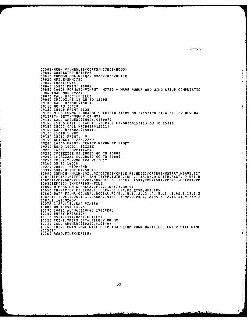
00001N#RUN *=;WESLIB/CORPS/H778OB(NOGO)09000 CHARACTER HFILE0509010 COMMON /MAIN/LQZ,LQX/C77805/HFILE09020 HFILE=5HH778O09030 LQZ=1;LQX=l09040 15000 PRINT 1000609050 10006 FORMAT(/"INPUT H7780 - WAVE RUNUP AND WIND SETUP,COMPUTATIO09060&NAL MODEL"//)09070 CALL HACCT(HFILE)09090 IF(LQZ.NE.1) GO TO 1500509100 CALL H7780($15011)09110 GO TO 1501009120 15005 PRINT 912509125 9125 FORMAT("CHANGE SPECIFIC ITEMS ON EXISTING DATA SET OR NEW DA09127&TA SET"/"NEW Y OR N")09130 CALL ANSWER($15006,$15007)09140 15006 CALL DETACH(1,,);CALL H77803($15011);GO TO 1501009150 15007 CALL H7780I($15011)09160 CALL H77802($15011)09170 15010 LQZ=20918n 15011 PRINT," "09190 CHARACTER ZZZZZZ4209200 16000 PRINT, "ENTER RERUN OR STOP"09210 READ 16001, ZZZZZZ09220 16001 FORMAT(A2)09230 IF(ZZZZZZ.EQ.2HRE) GO TO 1500009240 IF(ZZZZZZ.EQ.2HST) GO TO 2000009250 PRINT,"ERROR ** RETYPE"09260 GO TO 1600009270 20000 STOP;END09999 SUBROUTINE H7780(W)10000 COMMON /MAIN/LQZ,LQX/C77801/KFILE,FILEK(2)/C77802/NSTART,NSAVE,TIT1001OSLE(15),SITE(15),ITM,ITYPE,IWIND,IDES,ITAB,D1,D,COTTH,FACTU2,U61,U10020&L/C77803/X(50)/C77804/UF(50),T(50),H(50),TDUR(50),RP(20),HP(20),PP10030&EP(20),IX/C77805/HFILE10040 DIMENSION ALPHA(8),FI(7),WR(7),GD(5)10050 CHARACTER FILEKX8,TITLEX4,SITEM4,FILET*8,HFILEN510060 DATA FI,WR,GD,GRAV,SCOSAL,PI/O.,.5,1.,2.,3.,4.,5.,1.,1.08,1.13,1.210070&1,1.26,1.28,1.3,6.5882,.0161,.3692,2.2024,.8798,32.2,13.51091739,310075&.14159265/10078 C=22./15.;RAD=PI/180.10080 DO 10090 I=1,810090 10090 ALPHA(I)=(48-IK6)NRAD10100 ENTRY H77803(*)10110 NSTART=O;LQZ=1;KFILE=I10120 PRINT,"PERM DATA FILE;Y OR N"10130 CALL ANSWER($10200,$10140)10140 10140 PRINT,"WE WILL HELP YOU SETUP YOUR DATAFILE. ENTER FILE NAME10150&"10160 READ,FILEK(KFILE)
6o

H7780
10170 CALL H77801($10190);DS=DI;Ul1U2;U60=U6110180 GO TO 1037010190 10190 RETURN 110200 10200 PRINT,"DATAFILE NAME"10210 READ,FILEK(KFILE);N4START=I;LQZ=210220 ENTRY H77802(m);DS=Dl;U1=U2;U60=U6110230 10230 CALL TACHFILE(HFILE,$10190)10240 REWIND KFILE10250 READ(KFILE,10260) FILET10260 10260 FORMAT(4X,Ag)10330 10330 READ(KFILE,10350,END=10370) TITLE,SITE,IMM,ITYPE,IWINDIDES,10340&ITAB,Dl,D,COTTHFACT,U2,U61,(X(J),J=1,IMM);DS=DI;Ul=U2;U60=U6110350 10350 FORMAT(4X,15A4/4X,15A4/4X,513/4X,4F7.2/4X,2F7.2,7(/4X,8F7.2)10360&)10370 10370 IF(NSTART.EQ.O.AND.LQZ.EQ.2) GO TO 1042010375 PRINT 1038010380 10380 FORMAT("CHANGE ANY DATA BEFORE RUN,Y OR N")10390 CALL ANSWER($10400,$10420)10400 10400 LQZ=2;CALL H77801($10190)10410 GO TO 1023010420 10420 IF(IWIND.EQ.1) GO TO 1044010430 UL=Ul;U60=0.10440 10440 PRINT 10450,TITLE,SITE10450 10450 FORMAT(///"OUTPUT H7780 - WAVE RUNUP AND WIND SETUP,COMPUTA10455&TIONAL MODEL"//15A4/15A4/128X,"BASIC DATA"//)10460 PRINT 10470,DI,D,COTTH,FACT10470 10470 FORMAT(5X,29HDEPTH AT TOE OF EMBANKMENT = ,F7.2,3H FT/5X,22H104808AVERAGE WATER DEPTH = ,F7.2,3H FT/5X,19HEMBANKMENT SLOPE = ,F7.2,4104909iHH:1V/5X,35HSMOOTH SLOPE MODIFICATION FACTOR = ,F7.2)10500 IF(IWIND.EQ.1) GO TO 1054010510 PRINT 10520,UL10520 10520 FORMAT(5X,31HOBSERVED OVERLAND WIND SPEED = ,F7.2,4H MPH)10530 GO TO 1057010540 10540 PRINT 10550,U2,U6110550 10550 FORMAT(5X,24HONE MINUTE WIND SPEED ,F7.2,4H MPH/SX,26HSIXT10560&Y MINUTE WIND SPEED = ,F7.2,4H MPH)10570 10570 FE=O.;II:1;IJK:1510580 10580 J=O;IFItrO;SXA=O.10590 DO 10660 III,IJK10600 IF(IFIN.EQ.1) GO TO 1064010610 J=J+l10620 IF(J.EQ.8) IFIN:I10630 GO TO 1065010640 10640 J=J-110650 10650 XA=X(1)mCOS(ALPHA(J))XN210660 10660 SXA=SXA+XA10670 F=SXA/SCOSAL10680 IF(FE.GT.F) GO TO 1070010690 IK=II;FE=F10700 10700 IF(IJK.EQ.IMM) GO TO 10720
61
-UE&

H778o
10710 II=Il+l;tJK=IJK+1;GO TO 1058010720 10720 PRINT 1073010730 10730 FORTAT(//8X,58HRADIALS CORRESPONDING TO CRITICAL EFFECTIVE10740& FETCH INi MILES//)10750 ILZIK+1410760 PRINT 10770,(X(I),I=IK,IL)10770 10770 FCRtlAT(5X,8F7.2)10780 PR~INT 10790,FE10790 10790 FORr1AT(///25X,v'COT'PUTATIONAL RESULTS"//5X,23HEFFECTIVE WAVEIO8009FETCH = F7.2,6H MILES)10810 FES=FE*5280.;RMAX=0.10820 DO 10840 1:IK,IL10830 IF(RMAX.LT.X(I)) RMAX=X(I)10840 13840 CONTINUE10850 IF(FE.GE.5.) GO TO 1093010860 INC=010870 20870 INC=INC+110880 IF(FI(I?:C).GE.FE) GO TO 1090010890 GO TO 1087010900 10900 RG=(FE-FI( INC-1))/(FI(INC)--FI(INC-1))10910 R=RGx(W~R(INC)-WR(IN4C-1) )4WRC INC-1)10920 GO TO 1094010930 10930 R=1.310940 10940 IF(IWIND.EQ.0) GO TO 1126010950 UlzRxU110960 U120=.96*RNU6010970 U360=.88xR*U6010980 IJ60=U604R10990 IX=U1-U36011000 U=AINT(U360)11010 A60=ALOG(60. );A360=ALOG(360.);AU60=ALOG(U60);AU360=ALOG(U360)11020 US=U1xC11030 11030 GFU=GRAVXFES/USxx2;GFI=ALOG(GFU)11040 ALN=GD(2)*GF1x*211050 BLN=GD(3)*GFI-GD(4)11060 OL-N=GD(5)mGFI11070 TDIF=(US I'GDC 1))EXP(SQRT(ALN-BLN)+DLN) )/(GRAV)(60.)11080 IF(TDF.LE.60.) GO TO 1114011090 Al z(AU60-AU360 )/(A60-A360)11100 A0=EXP( AU60-Al*A60)11110 Al=ABS(I./A1)11120 TDC=(CxA0/US)X*A111130 GO TO 1119011140 11140 U30=.3WU1+.7*U6011150 IF(TDF.LE.30.) GO TO 1118011160 TDC=CU30-US/C)*30 ./(U30-_U60)+30.11170 GO TO 1119011180 11180 IDC:(U1-US/C)x29./(U1-U30 )+1.11190 11190 IF(TDF.GT.TDC) GO TO 1121011200 US=US+.1;GO TO 11220
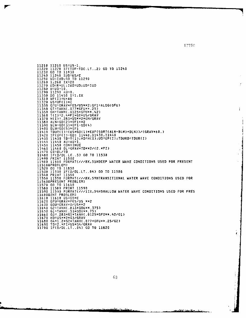
H77T80
11210 11210 LSzUS-I.11220 11220 IF(TDF-TDC.LT. .2) GO TO 1124011230 GO T0 11n3011240 11240 IUD=US/C11250 UD:IUD;CO TO 1129011260 l1260 IX=2011270 UD=RxUL;IUD=UD;UD=IUD11280 U=UD-10.11290 11290 AU=0.11350 DO 11450 I=l,IX11310 UF(I)rU+AU11320 US=UF(I)xC11330 GFUzGRAVxFES/USXX2;GF1=ALOG(GFU)11340 GT=TANH(.077XGFUXX.25)11350 GH=TANH(.0125*GFUX*.42)11360 T(I)72.4PI~iGTXUS/GRAV11370 H(I)=.283xUSN*2xGH/GRAV11380 ALN=GD(2)NGF1*x211390 BLN=GD(3)xGF1-GD(4)11400 DL14=GD(5)NGF111410 TDUR(I)=(UsxGD(1)*EXP(SQRr(ALN-BLN)+DLN))/cGRAV96o.)11420 IF(UF( I)-UD) 11440,11430,1144011430 11430 TD=T(I) ;HD=HCI);UD=UF(I);TDURD=TDUR(I)11440 11440 AU=AU+1.11450 11450 CONTINUE11460 11460 DL=GRAVxTDKK2/(2.*PI)11470 CO=DL/TD11480 IF(D/DL.LE. .5) GO TO 1153011490 PRINT 1150011500 11500 FORPIAT(///8X,51HDEEP WATER WAVE CONDITIONS USED FOR PRESENT11510&PROBLEM)11520 GO TO 1185011530 11530 IF(D/DL.LT. .04) GO TO 1158011540 PRINT 1155011550 11550 FORMAT(///8X,59HTRANSITIONAL WATER WAVE CONDITIONS USED FOR115608PRESENT PROBLEM)11570 GO TO 1161011580 11580 PRINT 1159011590 11590 FURIIAT(///11X,54HSHALLOW WATER WAVE CONDITIONS USED FOR PRES11600&ENT PRO3LEI)11610 11610 US=UDx'C11620 GFU=GRAVNFES/US **211630 GDU=GRAVYD/USxo211640 G2=TANH(.83GDU~x.375)11650 G1=TANH(.53xGDU)*.75)11660 G3.8xlTN(015G~*4/i11670 HD=USmx2xG3/GRAV11680 G4=1.2NG2xTANHl(.077AGFUx)W.25/G2)11690 TD=2.YPIYUSx(G4/GRAV11700 IF(O/DL.LT. .04) GO TO 11820
63

H7780
11710 ALEN=DL11720 GTA=GRAV*TD**2/(2.*PI)11730 GTB:2.NPI*D11740 11740 BLEN:GTAXTANH(GTB/ALEN)11750 DIFF=ALEN-BLEN11760 ADIFF=ABS(DIFF)11770 IF(ADIFF.LE.I.) GO TO 1181011780 IF(DIFF) 11800,11800,1179011790 11790 ALEN:ALEN-1.;GO TO 1174011800 11800 ALEN=ALEN+I.;GO TO 1174011810 11810 DL=ALEN;GO TO 1185011820 11820 TD=2.XPIXUSXG4/GRAV11840 DL=TD*SQRT(GRAV*D)11850 11850 FS=2.*FE11860 IF(FS.LE.RMAX) GO TO 1188011870 FS=Rr1AX11880 11880 S=FSXUDWx2/(1400.*D)11890 DS=DS+S11900 IF(ITYPE) 11910,12050,1231011910 11910 IF(COTTH.LT.5.) GO TO 1196011920 PRINT 1193011930 11930 FORMAT(/1X,57HPROGRAM CANNOT COMPUTE RUNUP ON SLOPES FLATTER119409THAN 1 ON 5)11950 GO TO 1231011960 11960 IF(COTTH.GT.2.) GO TO 1201011970 PRINT 1198011980 11980 FORMAT(/7OHPROGRAM CANNOT COMPUTE RUNUP ON A VERTICAL OR NEA11990&R VERTICAL EMBANKMENT)12000 GO TO 1231012010 12010 RS=HD/(.4+SQRT(HD/(GRAVTDX*2/(2.NPI)))wCOTTH)12020 PRINT 1203012030 12030 FORVAT(/2X,25HEMBANKMENT SLOPE - RIPRAP//)12043 GO To 1230012050 12050 IF(COTTH-1.5) 12060,12210,1206012060 12060 IF(COTTH.GE.2.25) GO TO 1211012070 FF-INT 1208012080 12080 FCRMAT(/1X,49HPROGRAM CANNOT COMPUTE WAVE RUNUP FOR SLOPE GI12090&VEN)12100 GO TO 1231012110 12110 IF(COTTH.GT.6.) GO TO 1219012120 ZA=(1.58-2.35/COTTH)(SQRT(HD/DS)12130 ZB=.092*COTTH-.2612140 ZF=ZA+ZB12150 SINBzI./SQRT(COTTHX*2+1.)12160 ZC= INBx(5.95/COTTH+1.5)12170 RS:HDNZC4(.123*DL/HD)X ZE12180 GO TO 1223012190 12190 RS=.4wTD-SQRT(GRAV*HD)/COTTH12200 GO TO 1223012210 12210 ZE=.56WSQRT(HD/DS)-.18
64

H7780
12220 RS=HDN2.3*(.123NDL/HD)*MZE12230 12230 RS=FACTXRS12240 IF(FACT-1.) 12280,12250,1228012250 12250 PRINT 1226012260 12260 FORMAT(/2X,25HEMBANKMENT SLOPE - SMOOTH)12270 GO TO 1230012280 12280 PRINT 1229012290 12290 FORMAT(/2X,34HEMBANKMENT SLOPE - MODIFIED SMOOTH)12300 12300 RSS=S+RS;GO TO 1234012310 12310 PRINT 1232012320 12320 FORMAT(/5X,51HRUNUP IS TO BE DETERMINED FROM FIG.13,ETL 111012330&-2-21)12340 12340 PRINT 12350,UD,TDURDHD,TD,DL,FS,S12350 12350 FORMAT(/5X,2OHDESIGN WIND SPEED = ,F7.2,4H MPH/5X,23HDESIGN12360& WIND DURATION = ,F7.2,4H MIN/5X,21HDESIGN WAVE HEIGHT = ,F7.2,3H12370& FT/5X,21HDESIGN WAVE PERIOD = ,F7.2,4H SEC/5X,32HDESIGN DEEP WATE12380&R WAVE LENGTH = ,F7.2,3H FT/5X,23HFETCH FOR WIND SETUP = ,F7.2,6H12390&MILES/5X,13HWIND SETUP = ,F7.2,3H FT)12400 IF(ITYPE.GT.0) GO TO 1244012410 PRIIT 12420,RS,RSS12420 12420 FORMIAT(5X,25HSIGNIFICANT WAVE RUNUP = ,F7.2,13H FT ABOVE SWL12430&/5X,32HTOTAL INCREASE IN WATER LEVEL = ,F7.2,13H FT ABOVE SWL)12440 12440 IF(ITAB.EQ.0) GO TO 1261012450 PRINT 1255012550 12550 FORrAT(///14X,45HWIND DATA AND DEEP WATER WAVE CHARACTERISTI12560&CS//6X,10HOVER WATERX,4HWIND,2X,2(6X,11HSIGNIFICANT)/6X,I OHWIND12570&5PEED,6X,8HDURATION,6X,IIHWAVE HEIGHT,6X,11HWAVE PERIOD/8X,5H(MPH12580&),11X,5H(MIN),10X,4H(FT),13X,5H(SEC)//)12590 PRINT 12600,(UF(I),TDUR(I),H(1),T(I),I=l,IX)12600 12600 FDRtIAT((6X,F7.2, 9X,F7.2,8X,F7.2,1OX,F7.2))12610 12610 IF(IDES.EQ.O.OR.ITYPE.GT.0) GO TO 1274012620 PRINT 1263012630 12630 FORMAT(///IX,7OHWAVE HEIGHTS AND WAVE RUNUP FOR WAVES OTHER12640& THAN THE SIGINIFICANT WAVE/3X,65H(NOTE- THE TERM WAVE EXCEEDEKCF12650& REFERS TO THE PERCENT OF WAVES IN/5X,44HA WAVE SPECTRUM THAT EXCE126609EDS A GIVEN VALUE.)//IX,2(12X,4HWAVE),8X,4HWAVE/OX,IOHEXCEEDANCE.12670&8X,6HHEIGHT,6X,6H RUNUP/1OX,1OHIN PERCENT,9X,4H(FT),8X,4H(FT)//i12680 DO 12710 I=1,2012690 AI=I;P=AI'100.;PPEP(I)=AI12700 RP(I)=RSXSQRT(ALOG(l./P)/2.)12710 12710 HP(I)=HDKRP(I)/RS12720 PRINT 12730,(PPEP(I),HP(I),RP(I),I=1,20)12730 12730 FORMAT((1OX,F7.2,9X,F7.2,5X,F7.2))12740 12740 IF(NSAVE.NE.I.AND.NSAVE.NE.2) GO TO 1277012750 KFILE=2; CALL H7780H(NSAVE)12760 KFILE=l12770 12770 RETURN12780 END14000 SUBROUTINE H7780I(*)14010 COMMON /MAIN/LQZ,LQX/C77801/KFILE,FILEK(2)/C77802/NSTART,NSAVE,TIT
65

17780
14020&LE(15),SITE(15),I MM,ITYPEIWINDIDES,ITAB,D1,D,COTTH,FACT,U2,U61,U14030&L/C77803/X(50)/C77805/HFILE14040 CHAPACTER FILEK , TITLEx4,SITEx4,HFILEx514050 IF(LQZ.EQ.3) GO TO 1409014060 ENTRY H77801(0)14070 IF(LQZ.EQ.2.OR.NSTART.EQ.0) GO TO 1409014080 LQZ=2;REWIND KFILE14090 14090 KKK=1414100 IF(LQZ.EQ.1) GO TO 1414014110 14110 CALL RERUN(KKK,LQX,JKL)14120 GO 10(14140,14180,14210,14240,14270,14310,14390,14440,14480,14510,14130&14540,14580,14630,14660,14730),JKL14140 1'140 PRINT,"AA-ENTER JOB TITLE < OR = 60 CHARACTERS"14150 READ 14160,TITLE14160 14160 FORMAT(15A4)14170 GO TO (14180,14110),LQZ14180 14180 PRINT,"AB-ENTER SITE ID < OR = 60 CHARACTERS"14190 READ 14160,SITE14200 GO TO(14210,14110),LQZ14210 14210 PRINT 1421514215 14215 FORMAT("AC-ENTER THE NUMBER OF RADIALS USED TO DETERMINE EFF14217&ECTIVE"/"FETCH DISTANCE;A MINIMUM OF 15 RADIALS IS REQUIRED")14220 READ,IMM14230 CO TO(14240,14110),LQZ14240 14240 PRINT 14245,IMM14245 14245 FORMAT("AD-ENTER THE "1,2," RADIAL LENGTHS IN MILES,SPEARATE14247& BY CO1MAS")14250 READ,(X(I),I=I,IMrl)14260 GO TO(14270,14110),LQZ14270 14270 PRINT 1428014280 14280 FORrIAT("AE-USE DESIGN OVERLAND WIND SPEED OR 1 MIN AND 60 MI14290&N WIND SPEED"/"AS IN ETL 1110-2-221;0,DESIGN;1,1 MIN AND 60 MIN")14300 READ,IWIND14310 14310 IF(IWIND.NE.1) GO TO 1435014320 PRINT,"AF-ENTER 1 MIN AND 60 MIN WIND SPEEDS,MPH"14330 READ,U2,U6114340 GO TO 1438014350 14350 PRINT,"AF-ENTER DESIGN OVERLAND WIND SPEED,MPH"14360 READ,UL14370 U2=L".;US1=O.14380 14330 GO TO(14390,14110),LQZ14390 14390 PRINT 1440014400 14400 FORMAT("AG-ENTER FACTOR FOR DESIGN WAVE;0,DESIGN WAVE IS SIG144109HIFICANI"/"WAVE;1,DESIGN WAVE IS OTHER RELATED WAVE")14420 READ,IDES14430 GO TO(14440,14110),LQZ14440 14440 PRINT,'AH-ARE DEEP WATER WAVE CHARACTERISTICS TO BE PRINTED;1445090,NO PRINT;1,PRINT"14460 READ,ITAB14470 GO TO(14480,14110),LQZ
66

H778o
14480 14480 PRINT,"AI-ENTER WATER DEPTH AT TOE OF STRUCTUREFT"l14490 READ,D114500 GO TO(14510,14110),LQZ14510 14510 PRINT,"AJ-ENTER AVERAGE WATER DEPTH ALONG WIND FETCH.FT"V14520 READ,D14530 GO TO(14540,14110),LQZ14540 14540 PRINT,"AK-ENTER COTANGENT OF ANGLE BETWEEN EMBANKMENT SLOPE145509AND HORIZONTAL"14560 RE'A D,COTTH14570 GO TO(14580,14110),LQZ14580 14580 PRINT1459014590 14590 FORMAT("IAL-ENTER FACTOR FOR REDUCING WAVE RUNUP ON SMOOTH SL146009OPE WHERE SLOPE IS"/"SLIGHTLY ROUGHER THAN SMOOTH")14610 READ,FACT14620 GO TO(14630,14110),LQZ14630 14630 PRINT,"1AM-ENTER SLOPE COVER ;-1,RIPRAP;0,SMOOTH;1,OTHER"14640 READ,ITYPE14650 GO TO(14660,14110),LQZ14660 14660 PRINT,"AN-SAVE TABULATED OUTPUT FOR GRAPHICS OR OTHER USE"14670 CALL ANSWER(S14680,$14770)14680 14680 NSAVE=1;KFILE=214690 FRINT,"FILE NAME"14700 READ,FILEK(KFILE)14710 CALL TACHFILE(HFILE,$14760)14720 14720 GO TO (14730,14110),LQZ14730 14730 KFILE~l14740 CALL H7780W($14/60,$14750)14750 14750 NsTrART=0;RETURN14760 14760 RETURN 114770 14770 HSAVE=0;GO TO 1472014780 END16000 SUBROUTINE H778OW(*,*)16010 COMM1ON /tAIH/LQZ,LQX/C77801/KFILE, FILEK(2)/C77802/NSTART,NSAVETIT16020&LE( 15) ,SITE( 15) , MM, ITYPE, IWIND, IDES, ITAB,D1,D,COTTH, FACT,U2,U61,U16030&L/C77803/X(50)/C77805/HFILE16040 DIMENSION LINE(13)16050 CHARACTER FILEKX8, TITLE*4,SILE*4,HFILEM516060 CALL TACHFILE(HFILE,$16240)16070 REWIND KFILE16080 LINE(1)=10016090 r18=IMM/8;NLIN=M8+616100 MR=IMM-M8x816110 IF(MR.EQ.0) GO TO 1613016120 M8=tl8+1;NLIN=NLIN+116130 16130 DO 16140 I=2,NLIN16140 16140 LINE(I)=LINE(I-1)+216150 WRITE(KFILE,16180) LINE~ ) ,LINE(2) ,TITLE,LINE(3) ,SITE,LINE(4) ,IMM,16160&ITYPE, IWIND, IDES, ITAB, LINE(5) ,Dl, D, COTTH, FACT, LINE(6) ,U2,U61, (LINE
16180 16180 FORMAT(I3,"' H7780"1,2(/I3,1X,15A4)/I3,1X,5I3/I3,X,4.F7.2/I3,1
67

H778o
16190&X,2F7.2, 7(/13, lX,8F7 .2))16200 CALL DETACH(KFILE.,)16210 IF(NSTART.EQ.1) GO TO 1625016220 HSTARTz016230 RETURN 216240 16240 RETURN 116250 16250 NSTART=0; RETURN16260 END20000 SUBROUTINE H7780H(NSAVE)20013 COMM'ON /C77801/KFILE, FILEK(2)/C77804/VF(50) ,T(50) ,H(50) ,TDUR(50) ,R20020&P(20) ,HP(20) ,PPEPC2O) ,IX20030 CHARACTER FILEKY8,AFILEX10,FORM*720040 DIMENSION LINE(50)20050 IF(NSAVE.NE.1) GO TO 2026020060 VWRITE(KFILE,20070) (IX, I=1,4)20070 20070 FORMAT("'10 H7780 07 07 EDGE"/"11 (07(/),(3X,7(1X,F7.2)))"/"12008092",4(lX,13),3(2X,"20")/"13",i(2X,"1"),3(2X,"15"))20090 WRITE(KFILE,20100)20100 20100 FORrIAT("14 CURVE DESIGNATIONS FOR H7780 ARE:"1/"15 1=OVER WA2011O8TER WIND SPEED",5X,"2=WIND DURATION"/"'16 3=SIGNIFICANT WAVE HEIGH20120&T 4=SIGNIFICANT WAVE PERIOD1'/"117 5=WAVE EXCEEDANCE"l,llX,16=WAVE201308 HEIGHT"/'"18 7=WAVE RUNUP"/"119 UNITS FOR ABOVE VARIABLES ARE:f/"T220140&0 MPHN1 IIN=2 SEC=4 FT=3,6,7 PERCENT=5"1)20150 20150 LINE(1)=10020160 DO 20170 1=2,IX20170 20170 LINE(I)=LINE(I-1)+220172 IF(IX.GE.20) GO TO 2018020174 DO 20176 I=IX+1,2020176 20176 LINE(I)=LINE(I-1)+220180 20180 WRITE(KFILE,20200) (LINE(I),UF(I) ,TDUR(I) ,H(I) ,T(I),PPEP(I),20190&HP(I),RP(I),I=1,20)20200 20200 F0Rr1AT( (I3,7(lX,F7.2)))20210 IF(IX.LE.20) GO TO 2024020220 WRITE(KFILE,20230) (LIHIECI) ,UF(I) ,TDUR(I) ,H(I) ,T(I),I=21,IX)20230 20230 FORM1AT( (I3,4(1X, F7 .2),4X,"10.",2(6X,"0.")))20240 20240 CALL DETACH(KFILE,,);NSAVE=220250 RETURN20260 20260 ENCODE(AFILE,20270) FILEK(KFILE)20270 20270 FORMAT("/"1,A8,1;"')20280 CALL ATTACH(KFILE,AFILE,3,0,,);1H11l20290 EHCODE(FORM,20300) LN20300 20300 FORMAT("(',I2,"l(/))")20310 READ(KFILE,FORM)20320 GO TO 2015020330 END
68

H7780
APPENDIX A
Bibliography
Ahrens, J. P. and McCartney, B. L., "Wave Period Effect on the Stabilityof Riprap," Civil Engineering in the Oceans/III Proceedings, AmericanSociety of Civil Engineers, 9-12 June 1975.
Battjes, J. A., "Wave Runup and Overtopping," Technical Advisory Commit-tee on Protection Against Inundation, Rijkswaterstaat, The Hague,Netherlands, 1974.
McCartney, Bruce L., "Wave Runup and Wind Setup on Reservoir Embank-ments," U. S. Army Corps of Engineers, Office of the Chief of Engineers,ETL 1110-2-221, November 1976.
Savage, R. P., "Wave Run-up on Roughend and Permeable Slopes," BeachErosion Board, Tech. Me. 109, March 1959.
Saville, T., Jr., McClendon, E. W., and Cochran, L. L., "FreeboardAllowances for Waves on Inland Reservoirs," ASCE, May 1962.
Saville, T., Jr., "Laboratory Data on Wave Run-up and Overtopping onShore Structures," Beach Erosion Board, Mem. 64, 1955.
Saville, T., Jr., "Wave Run-up on Shore Structures," Proc, ASCE, 82 nr.WW2, April 1956.
U. S. Army Corps of Engineers, "Computation of Freeboard Allowances forWaves in Reservoirs," ETL 1110-2-8, Office of the Chief of Engineers,1 August 1966.
U. S. Army Corps of Engineers, "Shore Protection Manual," CoastalEngineering Research Center, Fort Belvoir, Virginia, Volumes I, II, andIII, 3rd Edition, 1977.
U. S. Army Corps of Engineers, "Waves in Inland Reservoirs (SummaryReport on Civil Works Investigation Projects CW-164 and CW-165)," TM-132,Beach Erosion Board, Washington, D. C., November 1962.
A-1
__k__
H7780
APPENDIX B
Design Wind Speed and Wind DurationDeterminations
The method used in the present computer program for determining
the design wind speed, based on regional wind data, is for all practical
purposes consistent with the approach presented in ETL 1110-2-221. The
method presented in the ETL requires plotting two wind velocity-duration
curves, one based on regional wind and duration data, and one based on
data from wave forecasting curves for a given wave fetch. Example wind
velocity-duration curves are shown in Figure D-1 of the ETL. The inter-
section of the two curves are taken to yield the design wind speed and
corresponding wind duration. In the present scheme, equations are
written to describe the wind velocity-duration curve based on regional
wind data. The empirical formula used for constructing wind velocity-
duration curves in connection with the wave forecasting curves is
equated to the equations describing the wind velocity-duration based
on regional data. By an iterative process this technique yields the
design wind and corresponding wind duration. The procedures and
formulae used for determining these design values are covered in the
following paragraphs.
Three equations are used to reproduce the wind velocity-duration
curve for the regional wind data. One equation provides solutions for
wind speeds with durations from 1 to 30 minutes, one for wind speeds
with durations from 30 minutes to 60 minutes, and one for wind speeds
B-1

H7780
with durations from 60 to 360 minutes. As discussed in paragraph 5-C-1,
basic wind input consists of wind speeds corresponding to wind durations
of 1 and 60 minutes. The wind speeds for these durations are defined
symbolically as U and U6 0 , respectively. Equations of straight
lines are used to obtain solutions of wind duration as a function of
wind speed for wind durations ranging from 1 to 30 minutes and from 30
to 60 minutes. The 30-minute wind speed, U30 , is estimated by
S=(Ul + U60) (U U60) (B-)U30 = 2 -K 2(Bl
The factor K is taken to be 0.h0 based on the curve shown in Fig-
ure D-1 in the ETL. Thus this number is simply a reduction factor for
estimating the 30-minute wind speed. The wind duration tdc , for the
interval between 1 and 30 minutes as a function of the wind speed is
given by
t 1;+ 29 (U1 -U) 1 < td < 30 (B-2)tdc = 1 1 - U 30--tc-
and for the interval between 30 and 60 minutes by
30 (U30 - U)tdc 30 + 30; 30 < t < 60 (B-3)
U 60 -- tdc --
where U is the actual wind speed in the specific wind duration
interval.
In the wind duration interval between 60 and 360 minutes a
B-2
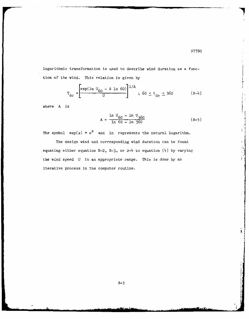
H7780
logarithmic transformation is used to describe wind duration as a func-
tion of the wind. This relation is given by
[exP(ln U 6 0 A ln 60)] / 6 BhT dc ... < 6O£tt 360 (B-4)
where A is
ln U -n UA= 60 360 (B-5)
1n 6o- ln 360
The symbol exp(x) = ex and ln represents the natural logarithm.
The design wind and corresponding wind duration can be found
equating either equation B-2, B-3, or B-4 to equation (4) by varying
the wind speed U in an appropriate range. This is done by an
iterative process in the computer routine.
B-3