thenewyorkhead · pdf filethenewyorkhead—aprecisestandardizedvolumeconductormodelfor eeg...
TRANSCRIPT

NeuroImage 140 (2016) 150–162
Contents lists available at ScienceDirect
NeuroImage
j ourna l homepage: www.e lsev ie r .com/ locate /yn img
TheNewYorkHead—Aprecise standardized volume conductormodel forEEG source localization and tES targeting
Yu Huang a, Lucas C. Parra a,⁎, Stefan Haufe b,c,⁎⁎a Department of Biomedical Engineering, City College of the City University of New York, New York, NY 10031, USAb Laboratory for Intelligent Imaging and Neural Computing, Columbia University, New York, NY 10027, USAc Machine Learning Department, Technische Universität Berlin, 10587, Berlin, Germany
⁎ Corresponding author.⁎⁎ Correspondence to: S. Haufe, Laboratory for IntComputing, Columbia University, New York, NY 10027, U
E-mail addresses: [email protected] (L.C. Parra), st(S. Haufe).
http://dx.doi.org/10.1016/j.neuroimage.2015.12.0191053-8119/Published by Elsevier Inc. This is an open acce
a b s t r a c t
a r t i c l e i n f oArticle history:Accepted 12 December 2015Available online 17 December 2015
In source localization of electroencephalograpic (EEG) signals, as well as in targeted transcranial electric currentstimulation (tES), a volume conductor model is required to describe the flow of electric currents in the head.Boundary element models (BEM) can be readily computed to represent major tissue compartments, but cannotencode detailed anatomical information within compartments. Finite element models (FEM) can capture moretissue types and intricate anatomical structures, but with the higher precision also comes the need for semi-automated segmentation, and a higher computational cost. In either case, adjusting to the individual humananatomy requires costly magnetic resonance imaging (MRI), and thus headmodeling is often based on the anat-omy of an ‘arbitrary’ individual (e.g. Colin27). Additionally, existing reference models for the human head oftendo not include the cerebro-spinal fluid (CSF), and their field of view excludes portions of the head and neck—twofactors that demonstrably affect current-flow patterns. Here we present a highly detailed FEM, which we callICBM-NY, or "New York Head". It is based on the ICBM152 anatomical template (a non-linear average of theMRI of 152 adult human brains) defined in MNI coordinates, for which we extended the field of view to theneck and performed a detailed segmentation of six tissue types (scalp, skull, CSF, gray matter, white matter, aircavities) at 0.5 mm 3 resolution. The model was solved for 231 electrode locations. To evaluate its performance,additional FEMs and BEMs were constructed for four individual subjects. Each of the four individual FEMs(regarded as the ‘ground truth’) is compared to its BEM counterpart, the ICBM-NY, a BEM of the ICBM anatomy,an ‘individualized’ BEM of the ICBM anatomy warped to the individual head surface, and FEMs of the other indi-viduals. Performance is measured in terms of EEG source localization and tES targeting errors. Results show thatthe ICBM-NY outperforms FEMs of mismatched individual anatomies as well as the BEM of the ICBM anatomyaccording to both criteria. We therefore propose the New York Head as a new standard head model to be usedin future EEG and tES studies whenever an individual MRI is not available. We release all model data online atneuralengr.com/nyhead/ to facilitate broad adoption.
Published by Elsevier Inc. This is an open access article under the CC BY license(http://creativecommons.org/licenses/by/4.0/).
Keywords:ICBM-NYVolume conductorHead modelForward modelLead fieldFinite element model (FEM)Electroencephalography (EEG)Inverse source imagingTranscranial electric current stimulation (tES)TargetingBoundary element model (BEM)Spherical harmonics expansion (SHE)
Introduction
Today, a multitude of tools are available to non-invasively ‘read andwrite the brain.’ Brain imaging technologies such as electroencephalog-raphy (EEG) allow one to track the activity of neuronal populationswithmillisecond precision. Conversely, transcranial electric stimulation (tES)induces changes in neuronal firing patterns by injecting electric cur-rents into the scalp. What is common to these technologies is that
elligent Imaging and [email protected]
ss article under the CC BY license (ht
they rely on a volume conductor model of the human head to establishthe connection between structures in the brain and electrodes locatedon the scalp. The ‘lead field’ or ‘forward model’ used for EEG inversemodeling relates a current source in the brain to the electric potentialsmeasured on the scalp (Sarvas, 1987; Mosher et al., 1999; Baillet et al.,2001; Vatta et al., 2010; Akalin Acar and Makeig, 2013; Vorwerk et al.,2014). What is called ‘forward model’ in tES captures the electric fieldgenerated in the brain when applying current to scalp electrodes(Wagner et al., 2007; Datta et al., 2009, 2012; Mendonca et al., 2011;Dmochowski et al., 2013). According to the reciprocity theorem, thetwo forward models are identical (Rush and Driscoll, 1969), so thatthe terms ‘forward model’ and ‘lead field,’ as well as ‘volume conductormodel’ and ‘head model,’ are interchangeable. The accuracy of such amodel determines the precision of both source localization in EEG andtargeting of specific brain structures using tES.
tp://creativecommons.org/licenses/by/4.0/).

1 Note that ICBM here only indicates that the head model is mainly derived from theICBM152 template. We are not affiliated with or part of the ICBM.
2 Available at http://www.bic.mni.mcgill.ca/ServicesAtlases/HomePage.
151Y. Huang et al. / NeuroImage 140 (2016) 150–162
Volume conductor models are commonly formulated as boundaryelement models (BEM) or finite element models (FEM). The classicthree-shell BEM is currently the predominant approach in EEG sourceimaging (Mosher et al., 1999) because of its computational efficiency,and because it can be readily constructed from structural magnetic res-onance images (MRI) using several freely available software packagessuch as LORETA (Pascual-Marqui et al., 1994; Fuchs et al., 2002),BrainVISA (Rivière et al., 2003; Geffroy et al., 2011), EEGLAB-NFT(Acar and Makeig, 2010), OpenMEEG (Gramfort et al., 2010), MNE(Gramfort et al., 2014), Brainstorm (Tadel et al., 2011), and FieldTrip(Oostenveld et al., 2011). In the BEM, the major tissues (brain,skull, scalp) are represented by tissue boundaries derived from theindividual's anatomy. However, BEMs are limited by the constraintthat boundaries must entirely enclose each other forming ‘shells’and that they must be reasonably smooth. Additionally, the cerebro-spinalfluid (CSF) is often not included, becausemost current automatedsegmentation tools do not resolve the thin CSF layer. All of these limitthe anatomical realism and accuracy of BE current-flow modeling(Vorwerk et al., 2014).
Most tES research use FEMs instead to encode finer anatomical de-tails more accurately at the resolution of the MRI. This includes thegyri/sulci of the cortex, the thin layer of CSF, and the small but delicatestructures of the skull (Datta et al., 2009, 2010, 2012; Mendonca et al.,2011).
As head anatomies vary greatly across the population, individualstructural information from MRI is required to build precise volumeconductor models. However, the acquisition of individual MRI is not al-ways possible and generally comes at a high cost. Further complicatingmatters, detailed finite elementmodeling requires manual interventionin the segmentation process (Datta et al., 2009, 2012). Despite the recentefforts to automate the segmentation (Huang et al., 2013; Huang andParra, 2015), and the FEM processing pipeline (Wolters et al., 2007;Windhoff et al., 2011; Dannhauer et al., 2012), there is still no fully auto-mated tool available for individualized FE modeling. Therefore, it is acommon practice in the tES community to use a detailed FEM builtfrom an ‘arbitrary’ individual as a reference model (Villamar et al.,2013; Truong et al., 2014; Richardson et al., 2014; Jones et al., 2015).
Themost commonly used individualmodel is Colin27 (Holmes et al.,1998), an average of 27 MRI scans of Colin J. Holmes. A BEM of theColin27 head is included in many neuroimaging software packages,such as LORETA (Pascual-Marqui et al., 1994), EEGLAB-NFT (Acar andMakeig, 2010), Brainstorm (Tadel et al., 2011), and FieldTrip(Oostenveld et al., 2011). An FEM of Colin27 has also been used previ-ously for tES. However, respective studies did not differentiate the CSFfrom the brain (Park et al., 2011; Jung et al., 2013) or used a limitedfield of view (FOV) (Salvador et al., 2010). The main problem withsuch reference models, however, is the obvious bias introduced byusing an arbitrary individual head, which is present even for templateswarped to a standard space such as the MNI space defined by the Mon-treal Neurological Institute.
Here we reason that, while in the near future it may remain infeasi-ble to compute highly detailed FEMs in individual anatomies at the scaleof larger studies, an improvementmay already be achieved by replacingarbitrary templateswith an unbiased population average. Currently, thebest available average over a population of individuals is the so-calledICBM152 head of the International Consortium for Brain Mapping(Mazziotta et al., 1995, 2001a, 2001b; Grabner et al., 2006; Fonovet al., 2009, 2011), which, thanks to advances in non-linear image regis-tration, has achieved a level of detail comparable to that of an individualhead.
We built an FEM based on the ICBM152 head to be used for EEGsource imaging as well as tES targeting. Specifically, we combined thehighly detailed brain image of the ‘non-linear’ ICBM152 v2009b tem-plate (0.5 mm3 resolution, (Fonov et al., 2009, 2011)) with the high-quality image of the non-brain area of the ICBM152 v6 template(1 mm3 resolution, (Grabner et al., 2006)). The FOV of the combined
model was extended down to the neck using an additional averagehead of 26 subjects provided by Chris Rorden (Huang et al., 2013).This composite model, which we term ICBM-NY,1 alias the ‘New YorkHead,’ includes scalp, skull, CSF, gray matter, white matter, and air cav-ities. To circumvent slow-processing times of detailed FEMs, the leadfields were precomputed and stored for 231 electrodes on the scalp fol-lowing the international 10–05 system. Performance of this ICBM-NYhead was evaluated by comparing it to FEMs of similarly detailed seg-mentations obtained from four individuals, which are used alternatelyas ‘ground truth,’ or ‘reference,’ heads. Additional comparisons wereperformedwith computationally efficient BEMand spherical harmonicsexpansions (SHE, (Nolte and Dassios, 2005; Marzetti et al., 2008; Haufeet al., 2008, 2011)) models of the reference anatomy, a BEM of theICBM152 anatomy, as well as ‘individualized’ BEMs that are adjustedto the individual outer shape of the head (Leahy et al., 1998; Darvaset al., 2006; Acar and Makeig, 2010), which is more readily availablevia 3D digitization hardware than individual MRIs. Performancemetricsinclude deviations of the lead fields from the ground truth, EEG localiza-tion accuracy, as well as tES targeting accuracy.
Methods
MRI acquisition and preprocessing
The McConnell Brain Imaging Centre of the Montreal NeurologicalInstitute (MNI, Montreal, Canada) provides three templates of humanheads2: MNI-305, Colin27, and ICBM152. MNI-305 (Evans et al., 1993;Collins et al., 1994) is a linear average of the T1-weighted structuralMRIs of 305 human heads. This average blurs the anatomical detailsneeded for realistic current-flow modeling. Colin27 (Holmes et al.,1998; Aubert-Broche et al., 2006) is an average of 27MRI scans of a sin-gle individual and may thus provide biased results. The ICBM152 tem-plate is an unbiased non-linear average of MRIs of 152 adult humansubjects, of which several versions exist. The older version, ICBM152 v6,better preserves detail of the skull and scalp anatomy (Mazziotta et al.,2001a; Grabner et al., 2006). The newer version, ICBM152 v2009b, betterpreserves anatomical details of the brain (Fonov et al., 2009, 2011). Bothcome in a symmetric and a regular version. As outlined in more detail inSegmentation and electrode placement section, the symmetric versionsof the ICBM152 v2009 and the ICBM152 v6 in combination with anotheraverage of 26 heads provide the anatomical basis for our model, whichwe call ICBM-NY, alias, the ‘New York Head.’
We also acquired MRI (1 mm3 isotropic resolution, T1-weighted) offour healthy individuals (denoted INDV1–4, all Caucasian male, agerange 27–45) at amagnetic field of 3 T. INDV1was scanned in a SiemensTrio scanner (Erlangen, Germany) using a gradient echo (GRE) se-quence with TE = 4.2 ms, TR = 2250 ms, 256 × 256 matrix scan with176 sagittal slices. INDV2 was also scanned in a Siemens Trio scannerusing a GRE sequence with TE= 2.3 ms, TR = 1900ms, 280 × 320ma-trix scan with 208 sagittal slices. INDV3 was scanned in a General Elec-tric Signa Excite HD scanner (Fairfield, CT) using a GRE sequence withTE= 2.2 ms, TR = 7.3 ms, 256 × 256 matrix scan with 252 axial slices.INDV4 was scanned in a Siemens Trio scanner using a magnetizationprepared rapid acquisition gradient echo (MPRAGE) sequence withTE = 2.98 ms, TR = 2300 ms, 240 × 256 matrix scan with 160 sagittalslices.
All four individual MRIs were registered to the ICBM152 v6 headtemplate using the ‘Coregister’ function (Collignon et al., 1995) provid-ed by the Statistical Parametric Mapping (SPM8) package (WellcomeTrust Centre for Neuroimaging, London, UK) inMatlab (TheMathworks,

152 Y. Huang et al. / NeuroImage 140 (2016) 150–162
Natick, MA). The registration yielded a 6-parameter affine transformconsisting of a rotation and translation, but no scaling or shearing.This transform,M1, defines a native reference-space with the origin lo-cated at the anterior commissure for each subject. All lead fields andother data reported in the following are expressed in these native-space coordinates.
In addition to the MRI-to-native transform, a 12-parameter affinetransform (M2) from the individual native space to the MNI reference-space defined by the MNI-305 template (Evans et al., 1993; Collinset al., 1994) was calculated for each individual using the ‘Normalise’function (Friston et al., 1995) in SPM8. These transforms were usedlater to match cortical locations in different anatomies (see Mappingbetween cortical locations of different anatomies section).
Notice that none of the above-mentioned transforms was applied tothe actualMRI data. Bothwere only stored for later usage.Moreover, no-tice that thenative space of the ICBM152head is by construction alignedwith the MNI space.
Segmentation and electrode placement
The two versions of the ICBM152 (v6 and v2009b), as well as thefour individual heads (INDV1–4) were segmented using a probabilisticsegmentation routine (New Segment, an extension of Unified Segmen-tation, (Ashburner and Friston, 2005)) in SPM8. For the anatomical priorprobability, we used a tissue probability map (TPM) developed by ChrisRorden (CR-TPM, (Huang et al., 2013)). This resulted in a segmentationof six tissue types: gray matter (GM), white matter (WM), CSF, skull,scalp, and air cavities. A custom Matlab script was used to correct forsegmentation errors made by SPM, such as rough tissue surfaces, dis-continuities in CSF, and skull layers, and disconnected regions (Huanget al., 2013). The remaining errors in continuity and anatomical detailswere manually corrected in ScanIP 4.2 (Simpleware Ltd., Exeter, UK).
Since the ICBM152 v2009b is characterized by a higher resolutionand better image quality in the brain, but poorer quality in the non-brain region compared to the ICBM152 v6, the non-brain tissues (CSF,skull, scalp, air) obtained from ICBM152 v6 were registered to the MRIspace of ICBM152 v2009 using SPM's Coregister routine, and resliced.This process performs generally well except that some of the voxels inthe resliced CSF overlap with brain (mainly GM) voxels. The overlap-ping parts of the CSF were removed from the brain by Boolean subtrac-tion, resulting in discontinuities of the CSF surface. To correct for this,the CSF was combined with the brain, dilated by a spherical structuralelement of 1mmdiameter, and then subtracted from the brain. Residualoverlap of CSF and skull was subtracted from the CSF, and resulting dis-continuities on the skull were manually corrected by subtracting voxelsfrom the scalp. After these operations, a combined ICBM152 head with0.5 mm3 resolution and abundant anatomical details in both brain andnon-brain tissues was obtained. The FOV of this combined image, how-ever, only covers the brain area. tES modeling work has demonstratedtheneed to include the entire headdown to theneck for realistic currentflow, in particular in deep-brain areas and the brainstem (Huang et al.,2013). To this end, the CR-TPM, which has an FOV covering the wholehead, was registered to the voxel space of the ICBM152 v2009 template,resliced, and fused inferiorly to the combined ICBM152 head. Thus, wefused the brain (GM, WM) obtained from ICBM152 v2009b with thenon-brain tissues obtained from ICBM152 v6 and the lower head ob-tained from CR-TPM into a new, high-resolution (0.5 mm3), whole-headmodel referred to as the ICBM-NY (NewYork) head. 3D renderingsof the tissue compartments of the ICBM-NY are shown in Fig. 1.
For all heads, electrodes were placed on the scalp surface automati-cally using a customMatlab script described in (Huang et al., 2013). Spe-cifically, we used a subset of the 165 electrode locations defined in the10–05 system (Oostenveld and Praamstra, 2001).
In addition, two rows of electrodes below the ears and four addi-tional electrodes around the neck were placed to allow for targetingof deeper cortical areas, and for the use of distant reference
electrodes in tES. To avoid complications when automatically placingelectrodes near or behind the ear-lobes, the electrodes TP9 and TP10were omitted. A total of 231 electrodes were placed for each head(see Fig. 1).
Note that the electrodemodeling differs here fromwhat is describedin (Huang et al., 2013). We did not physically model the electrodes andthe underlying gel, because, due to the dense electrodemontage consid-ered, the proximity of the electrodes on the scalp surface wouldartificially increase surface conductance. Instead, each ‘electrode’ is rep-resented as a small triangular area corresponding to the surface of theclosest tetrahedral mesh-element (see below).
Finite element modeling
A FEM with adaptive tetrahedral element sizes was generated foreach head using ScanIP (+ScanFE Module, ScanFE-Free algorithm).Laplace's equation (−∇⋅(σE)=0) was then solved (Griffiths, 1999) inAbaqus 6.11 (SIMULIA, Providence, RI) for the electric field distributionE in the head. Each tissue type was assigned a conductivity σ as inHuang et al. (2013). The boundary conditions were set to: insulatedon the scalp surface, grounded on electrode location Iz, and 1A/m2 of in-ward current density on each of the other electrode locations. Thus, foreach head, we obtained 230 solutions for electric field distributionrepresenting the ‘forward model’ or ‘lead field.’ For subsequent analy-ses, gray matter voxels were extracted. The lead fields evaluated atthese voxels were calibrated to correspond to 1 mA current injectionsfrom the scalp surface, whereas the corresponding MRI voxel coordi-nates were converted into the native coordinate system of each headusing the individual transform matrix M1 (Fig. 3).
Note that by including CSF and air cavities and by distinguishing be-tween gray and white matter, we here closely follow the guidelines forprecise electrical modeling of the head formulated by Vorwerk et al.(2014), who identified these factors as being more important than thedistinction of skull spongiosa and compacta, as well as the modelingof white matter anisotropy.
Boundary element and spherical harmonics modeling
For the purpose of comparison, we generated BEMs using conven-tional procedures as follows. Using the ‘Morphologist’ pipeline ofBrainVISA (http://brainvisa.info/), high-resolution meshes of the corti-cal surfacewere obtained (with about 75,000 nodes) for all four individ-ual heads, as well as the ICBM152 v2009 head from their T1-weightedMR images. Fig. 2 shows the extracted cortical surfaces. Note that thesmoothed surfaces shown in the right panel of the figure are solelyused for plotting. Surfacesmeshes of the brain, skull, and scalp compart-ments comprising 1922 nodes each were extracted using the Brain-storm package (Tadel et al., 2011). Within this 3-shell geometry, theEEG forward problem was solved using BEM as implemented by theOpenMEEG package (Gramfort et al., 2010), as well as using sphericalharmonics expansions (SHE) of the electric lead fields (Nolte andDassios, 2005). The electrical conductivities used for the brain, skull,and scalp compartments were σ1=0.33 S/m, σ2=0.041 S/m, andσ3=0.33 S/m, respectively.
Note that we used the ‘regular’ ICBM152 head for BEM and SHEmodeling to demonstrate what results would be obtained usingexisting freely available toolboxes. However, since these modelsrely on a three-shell geometry, key features of the ICBM-NY such asan extended FOV, inclusion of CSF, and a highly detailed skull arelargely ignored. Specifically, the outer shells generated by Brain-storm are cut off a few centimeters below the brain. Moreover, aconstant skull thickness of 4 mm is assumed, and the CSF is omitted.We would therefore expect similar BEM/SHE results for the ICBM152and ICBM-NY anatomies.

Fig. 1. Segmentation of the ICBM-NY head into six different tissue types. From (a) to (f): scalp (with 231 electrodes placed), skull, cerebro-spinal fluid, gray matter, white matter, aircavities. Note that the disc electrodes and underlying gel in (a) are not physically modeled. Instead, they are represented by a single tetrahedral mesh-element on the scalp surface.
153Y. Huang et al. / NeuroImage 140 (2016) 150–162
Generation of individualized warped ICBM templates
In addition to the ICBM152 and the INDV1–4 heads, four individual-ized versions of the ICBM152 template were constructed by warping itto match the individual shape of the scalp. To this end, the ICBM152head surface was morphed to fit the electrodes locations on each ofthe four individual heads INDV1–4 (Leahy et al., 1998; Tadel et al.,2011). The warping was carried out in Brainstorm. Note that buildingsuchmodels is possible in practice using 3D digitization hardwarewith-out requiring any individual structuralMRI data. The estimatedwarpingtransformationswere subsequently applied to all precomputed surfacesof the ICBM152 head. Lead fields were computed in these warped anat-omies using BEM (OpenMEEG toolbox), giving rise to four ‘individual-ized’ (as opposed to ‘individual,’ which refers to the use of individualstructural MR images) head models.
Quantitative comparison of head models
We quantitatively evaluated how well the proposed ICBM-NY headmodel approximates the current flow in the individual heads INDV1–4and compared this to other commonly used head models. For thisstudy, the FEM calculated in each individual anatomy was regarded asthe ‘ground truth’ for that individual and will be referred to as the ‘ref-erence head model’ (REF FEM). Head models differing from REF FEMare called approximate and can arise for two reasons: 1) an incongruent
anatomical basis (as is the case if we use a different individual for com-parison) and 2) an electrical model different from FEM (e.g., a BEM,which can only approximate the more detailed FEM even it is appliedto the reference anatomy).
Besides the ICBM-NY, we evaluate the following head modelsagainst the ground truth provided by REF FEM: a BEM and a SHE electri-cal model of the reference anatomy (denoted as REF BEM and REF SHE,respectively), FEMs of three other individuals' anatomies (summarizedunder the term INCG FEM), a BEM of the ICBM152 anatomy (ICBMBEM), and an ‘individualized’ BEM of the ICBM152 anatomy (denotedasWARP BEM). All lead fields were re-referenced to the common aver-age of the selected channels. A subset of 108 electrode locationswas se-lected for the lead field comparisons, and EEG source localization studydescribed below. The distribution of these electrodes across the scalp isshown in Fig. 2 for all heads. For the tES targeting study described inAssessment of tES targeting accuracy section, the full set of 231 elec-trodes was used.
Mapping between cortical locations of different anatomiesComparisons between reference and approximate head models
were carried out on 10,004 points covering the entire cortical surfacefor each head. To this end, mappings between locations in the referenceanatomy and locations in the anatomy of the approximate headmodelshad to be established (see Fig. 3). All anatomies were transformed intothe native space of the reference head (blue). Models based on the ref-erence anatomy (REF BEM and REF SHE; blue, top row in the figure) are

ICB
M-N
YIN
DV
1IN
DV
2IN
DV
3IN
DV
4
Fig. 2. The ICBM-NY anatomy as compared to four individual heads (INDV1–4). Left: head (outer shell of a BEM model) surface with the subset of the 108 electrodes used for thequantitative evaluation. Center: cortical surface. Right: smoothed cortical surface used for plotting. Cortical sulci are marked in dark color.
154 Y. Huang et al. / NeuroImage 140 (2016) 150–162
already in that space and require no transformation. For WARP BEM(green, second row), the underlying ICBM152 anatomy is by construc-tion aligned with the native space of the reference anatomy throughthe non-linear warping procedure applied within Brainstorm. ForICBM-NY and ICBMBEM(green, third row), the ICBMheadwasmappedfrom its native space (the MNI space) into the reference head's nativespace using the inverse of the affine transformation M2
ref described inMRI acquisition and preprocessing section. For INCG FEM (red, fourthrow), the same was achieved by consecutively applying the native-to-MNI affine transformation of the incongruent anatomy (M2
incg) and theMNI-to-native affine transformation of the reference anatomy (inverseof M2
ref). Once model anatomies had been transformed to the referencehead's native space, matching locations were determined for eachpoint of the reference model by selecting the closest point in the ap-proximate anatomy in terms of Euclidean distance. Note that all spatialtransformations were solely applied to the coordinates of the incongru-ent anatomies for the purpose of matching locations. The actual leadfields remained unchanged.
Assessment of lead field approximation accuracy
We compared the lead fields of all approximate headmodels (ICBM-NY, REF BEM, REF SHE, INCG FEM, ICBM BEM, WARP BEM) to those ofthe reference model (REF FEM). To obtain topographical distributions
of the errors, this comparison was performed separately for each loca-tion in the reference anatomy, where lead fields of the approximatehead models were evaluated at the matching locations as outlinedabove.
Let the M×3 lead fields of the reference and incongruent modelat the ith cortical location, ri, be denoted by Lrefi and Lappri , where Mis the number of electrodes. These lead fields are expressed with re-spect to the coordinate axes of the respective native spaces of theunderlying anatomies, which are in general not aligned. Therefore,Lrefi and Lappri are only comparable up to rotations. This problem couldbe circumvented by applying the spatial transformations between na-tive spaces based on the transformation matrices M2 also to the leadfields. However, these transformations involve not only rotations butalso scalings and shearings, which may bias the results. Instead oftransforming the lead fields, we therefore decided to base our quantita-tive evaluation entirely onmeasures that are invariant to rotations in 3Dspace.
Adopting anEEG terminology,we compare leadfields in terms of thestrength of their resulting scalp potentials relative to each other, as wellas the similarity of these scalp potentials. The relative lead field strength(termed gain) at cortical location i is defined as.
Gi ¼ 10 log10jjLiref jj2FjjLiapprjj2F
!; ð1Þ

Fig. 3.Mapping betweendifferent anatomies.M1 is a 6-parameter affine transformmapping locations fromMRI voxel space into thenativeworld-space as described inMRI acquisition andpreprocessing section.M2 is a 12-parameter affine transformmapping locations from native world-space into MNI space. To identify matching points in the native space of the referencemodel REF FEM (blue), all locations are mapped into this space, and closest points in the two models are selected based on smallest Euclidean distance. REF BEM and REF SHE (blue, firstrow) are already in the native space of REF FEM.WARP BEM (green, second row) is in the correct space after being warped. ICBM BEM and ICBM-NY (green, third row) are mapped fromthe MNI space into the native space of the reference. INCG FEM (red, fourth row) is first mapped into MNI space and then mapped into the native space of the reference model. Data arenever resampled in any of these mappings.
155Y. Huang et al. / NeuroImage 140 (2016) 150–162
and is measured on a dB scale. Here, || ⋅ ||F2 is the sum of the squared en-tries of a matrix. Note that Gi is independent of the orientation of thesource currents, as it is unaffected by arbitrary rotations Lrefi ←Lrefi Rt
and Lappri ←Lappri Ra using orthogonal rotation matrices Rt and Ra.Lead field correlation is defined based on the largest principle angle
between the subspaces spanned by Lrefi and Lappri (Golub and Van Loan,2012) and is computed using Matlab's subspace command, again foreach location i. Just as the gain, the subspace angle is independent of ro-tations within 3D space. However, while the gain measures exactly thescale ratio of two lead fields, the subspace angle is independent of anyscaling. It is therefore a suitable measure of subspace correlation. Herewe consider subspace angles normalized to the interval [0,1], where 1stands for completely disjoint (orthogonal) lead fields, and 0 standsfor lead fields that are identical up to arbitrary linear transformations.Subspace correlation is defined as 1 − subspace angle and is higherfor more similar lead fields.
Notice that the two evaluation metrics were chosen because theyapproximately reflect the criteria used to measure tES targeting accura-cy (gain), as well as to determine source locations in EEG source imag-ing (subspace correlation).
Assessment of EEG source localization accuracy
We simulated an EEG inverse source reconstruction setting in orderto assess the consequences of using an approximate headmodel in prac-tical terms. Scalp potentials were generated for the reference headmodel REF FEM, while localization was carried out using either of theapproximate models REF BEM, REF SHE, ICBM-NY, ICBM BEM, INCGFEM, andWARPBEM. Similar to the evaluation of approximation quality
of the lead fields described above, the simulation was carried out sepa-rately for each cortical location, yielding a spatial distribution of locali-zation errors. To this end, in the i-th run of the simulation, the leadfield Lrefi at location ri was projected onto the normal vector of the cor-tical surface at ri, ni, leading to a singleM-dimensional vector lrefi =Lrefi ni
representing the scalp potential that would be generated by a dipolarcurrent source at ri oriented perpendicular to the cortical surface. Thispotential was subsequently regarded as a pseudo EEG measurement.
Localizationwas carried out by sweeping through all cortical locationshj of the approximate head model and comparing lrefi to Lapprj using thesubspace correlation criterion. Note that this approach is similar tothe classical ‘multiple signal classification’ (MUSIC) scan (Schmidt,1986; Mosher and Leahy, 1999). The location hjopt leading to maximalsubspace correlation was defined as the estimated source location inthe approximate head model. After transforming hjopt to the nativespace of the reference head using the procedures outlined inMapping between cortical locations of different anatomies section,the Euclidean distance to ri was computed and defined the localiza-tion error. Note that, through the use of subspace correlation for de-fining source locations, this part of the evaluation is also invariantw.r.t. rotations of the native spaces of the reference and approximateanatomies.
Assessment of tES targeting accuracy
The performance of the ICBM-NYwas also evaluated in terms of tEStargeting accuracy. In targeting of transcranial currents,models are usedto optimize the current applied to each electrode location with the goalof increasing either focality or intensity of the stimulation in the brain

156 Y. Huang et al. / NeuroImage 140 (2016) 150–162
(Im et al., 2008; Park et al., 2011; Dmochowski et al., 2011, 2013). Herewe use the algorithm described in Dmochowski et al. (2011).Specifically, the electric field perpendicular to the cortical surface atthe target location is maximized, with the total injected current beingconstrained to a safe limit (typically no more than 2 mA).
Each model may give different optimal electrode currents resultingin different electric field in the brain. To see how much the differentmodels deviate from each other in this regard, we optimized intensityon target using the ‘ground truth’ model (REF FEM) as well as each ofthe approximate or incongruent models (REF BEM, REF SHE, ICBM-NY,ICBM BEM, INCG FEM, and WARP BEM). We did this for each corticallocation ri to obtain a corresponding optimal electric field distributionErefi (these areN×3matrices withN=10,004 representing the numberof corticalmesh points in themodel).We also optimized intensity at thecorresponding locations in the approximate models, where correspon-dence is determined following Mapping between cortical locations ofdifferent anatomies section,, and applied those optimal currents back
ICB
M-N
YIN
CG
FE
MIC
BM
BE
MW
AR
PB
EM
RE
FB
EM
RE
FS
HE
INDV1
Fig. 4. Lead field gain observed across all cortical locationswhen approximating a reference heabased on an incongruent anatomy or uses a different electrical model in thematching referencewas carried out using ICBM-NY—the ‘New York Head’ model, INCG FEM—FEMs of three differelement model of the ICBM152 template, WARP BEM—a BEM of a version of the ICBM152 temof the reference anatomy, and REF SHE—a spherical harmonics expansions model of the referoften not available in practice, and thus have an advantage over a fixed incongruent head. Upthe cortical locations of four individual subjects INDV1–4. Outliers are not plotted. Lower panINDV2–4 (left lateral view).
to the reference model to obtain Eappri . This is the field distribution onewould generate in the ‘true’ head if only approximate models wereavailable for targeting.
Two metrics were defined to assess the targeting performance.The first one evaluates how different the intensities of the twoelectric fields Eref
i and Eappri are at the target, measured by the relative
error
relErri ¼ jEiapprðriÞ−Eiref rið ÞjEiref rið Þ
: ð2Þ
Here, Ei(ri) is themagnitude of the electric field at the target riwhenoptimizing for that same target location. The secondmeasure evaluateshow well the peak intensities of the two fields Erefi and Eappri overlap onthe cortex. Thismeasure was used because clinicians are particularly in-terested in the areas of peak activation (presumed to correspond to
INDV2 INDV3 INDV4
dmodel (a finite elementmodel of an individual's anatomy) by a headmodel that is eitheranatomy. Values closer to zero indicate better approximation performance. Approximationent individual anatomies incongruent with the one being tested, ICBM BEM—a boundaryplate that has been warped to fit the outer shape of the reference head, REF BEM—a BEMence anatomy. Note that the lower three head models use individual information that isper panels: Median, 25th and 75th percentile, and most extreme values attained acrossels: topographical distributions of the gain for subject INDV1 (four views) and subjects

157Y. Huang et al. / NeuroImage 140 (2016) 150–162
desired neurophysiological effects). The Jaccard index (Jaccard, 1901)was used to quantify the similarity of the spatial distributions of thepeak areas. It is given by
Jacci ¼ jPiref ∩ Pi
apprjjPi
ref ∪ Piapprj
; ð3Þ
where Prefi and Pappri are the peak areas (binary masks) corresponding
to field intensities Erefi and Eappr
i larger than the 75th percentile. AJaccard index close to 1 indicates perfect overlap between the twoareas, while an index of 0 indicates that the two areas are entirelydisjoint. relErri and Jacci were calculated for all cortical locations riin REF FEM, yielding a spatial distribution of targeting errors. Notethat although in the approximate head model, the electric field ismaximized along the normal direction of the cortical surface at thetarget, the two error metrics do not assume any fixed orientation ofthe electric field in the reference head and are hence invariantw.r.t. rotations between the native spaces of the reference and approx-imate anatomies.
For boundary element and spherical harmonics modeling, differentconductivity values are used compared to FE modeling (Finite elementmodeling, Boundary element and spherical harmonics modeling, and
ICB
M-N
YIN
CG
FE
MIC
BM
BE
MW
AR
PB
EM
RE
FB
EM
RE
FS
HE
INDV1
Fig. 5. Subspace angle (1-subspace correlation) achieved across all cortical locations when appthat is either based on an incongruent anatomy or uses a different electrical model in the matgraphs analogous to Fig. 4; see caption for detail.
Generation of individualized warped ICBM templates sections). There-fore, the intensity achieved at the target can be biased when using aBEM, WARP BEM, or SHE model to approximate the reference modelREF FEM. This bias was corrected by computing an optimal global scalarcoefficient that minimizes (in least-square sense) the differencebetween the lead fields of REF FEM and any non-FEM head model.This way, reference and approximate lead fields were brought to asimilar scale.
Results
Figs. 4–8 depict the results of the quantitative evaluation of theICBM-NY head model as compared to competing models in terms offive different error measures. The distributions of the errors shown inthe upper panel of each figure are pooled over the four individualreference heads. In all instances, it is assumed that the individualFEMs (REF FEM) are the ‘ground truth,’while the various other modelsare approximations. ICBM-NY provides the performance of the pro-posed New York Head when tested on the four individual FEMs. INCGFEM tests howwell a detailed FEMof an individual can replicate another(incongruent) individual. Here, results are further pooled over the threeincongruent individual heads serving as approximations (e.g., INDV2–4when INDV1 is the reference anatomy). WARP BEM, REF BEM, and REF
INDV2 INDV3 INDV4
roximating a reference head model (the FEM of an individual's anatomy) by a head modelching reference anatomy. Smaller values indicate better approximation performance. All

ICB
M-N
YIN
CG
FE
MIC
BM
BE
MW
AR
PB
EM
RE
FB
EM
RE
FS
HE
INDV1 INDV2 INDV3 INDV4
Fig. 6. Localization error incurred for dipolar sources placed across all cortical locations when performing EEG source imaging in an approximate headmodel, which is either based on anincongruent anatomy or uses a different electrical model in the matching reference anatomy. All graphs analogous to Fig. 4; see caption for detail.
158 Y. Huang et al. / NeuroImage 140 (2016) 150–162
SHE indicate the results for various approximate BEMmodels tested onthe four individual FEMs. The lower panels of the figures depict topo-graphical distributions of the errors made for each of the four referenceanatomies INDV1–4.
Lead field approximation accuracy
Figs. 4 and 5 depict the results of the leadfield approximation assess-ment in terms of gain and subspace correlation. The proposed ICBM-NYmodel as well as ICBM BEM slightly underestimates the global currentintensity as compared to REF FEM. In contrast, REF BEM and WARPBEM slightly overestimate the overall current flow. REF SHE and thethree incongruent individual models (INCG FEM) pooled together pro-vide the most unbiased estimate of current flow. The range of gain fac-tors attained by all models is relatively narrow, extending from −4 to4 dB. In terms of subspace correlation (Fig. 5), ICBM-NY outperformsINCG FEM, ICBM BEM, and REF SHE, while being on par with WARPBEM. Here, ICBM-NY is only outperformed by a BEM computed in thereference anatomy (REF BEM).
The spatial distributions of the leadfield approximation errors large-ly reflect the anatomical variation in our sample of four individual refer-ence anatomies. A common pattern is, however, that models based onthree-shell approximations (ICBM BEM, WARP BEM, REF BEM, andREF SHE) tend to overestimate the lead field intensity in more
superficial frontal, central, parietal, and occipital regions and to under-estimate the intensity in the deeper parts of the temporal lobe (lowerpanel of Fig. 4). FEMs (ICBM-NY and INCG FEM), in contrast, seem tooverestimate the intensity in the temporal lobes. The subspace correla-tion (lower panel of Fig. 5) tends to be lowest in deep areas such as thetips of the temporal lobes for three-shell models, whereas for FEMs, thelowest correlations are achieved in frontal, parietal, or occipital areasdepending on subject. Notably, the achieved subspace correlation dif-fers substantially between subjects for ICBM-NY, INCG FEM, and ICBMBEM, whereas the variation for individual and individualized models(WARP BEM, REF BEM, and REF SHE) is much smaller.
EEG source localization accuracy
Fig. 6 depicts the results of the EEG source localization study.ICBM-NY achieves a median localization error of 10.3 mm,outperforming INCG FEM (13.3 mm) and ICBM BEM (10.8 mm).However, individual and individualized models employing knowl-edge of the reference anatomy yield better localization performance(REF BEM: 6.9 mm, REF SHE: 8.9 mm, WARP BEM: 8.4 mm). Thetopographical distributions of the localization errors largely resem-ble the distributions of the lead field subspace correlations shownin Fig. 5, reflecting the choice of subspace correlation as the criterionfor selecting source locations.

ICB
M-N
YIN
CG
FE
MIC
BM
BE
MW
AR
PB
EM
RE
FB
EM
RE
FS
HE
INDV1 INDV2 INDV3 INDV4
Fig. 7. Relative error in electric field intensity incurred across all cortical locationswhen targeting a cortical location in individual subjects using an electrodemontage optimized in a headmodel that is either based on an incongruent anatomy or uses a different electrical model in the matching reference anatomy. Smaller values indicate better targeting performance. Allgraphs analogous to Fig. 4; see caption for detail.
159Y. Huang et al. / NeuroImage 140 (2016) 150–162
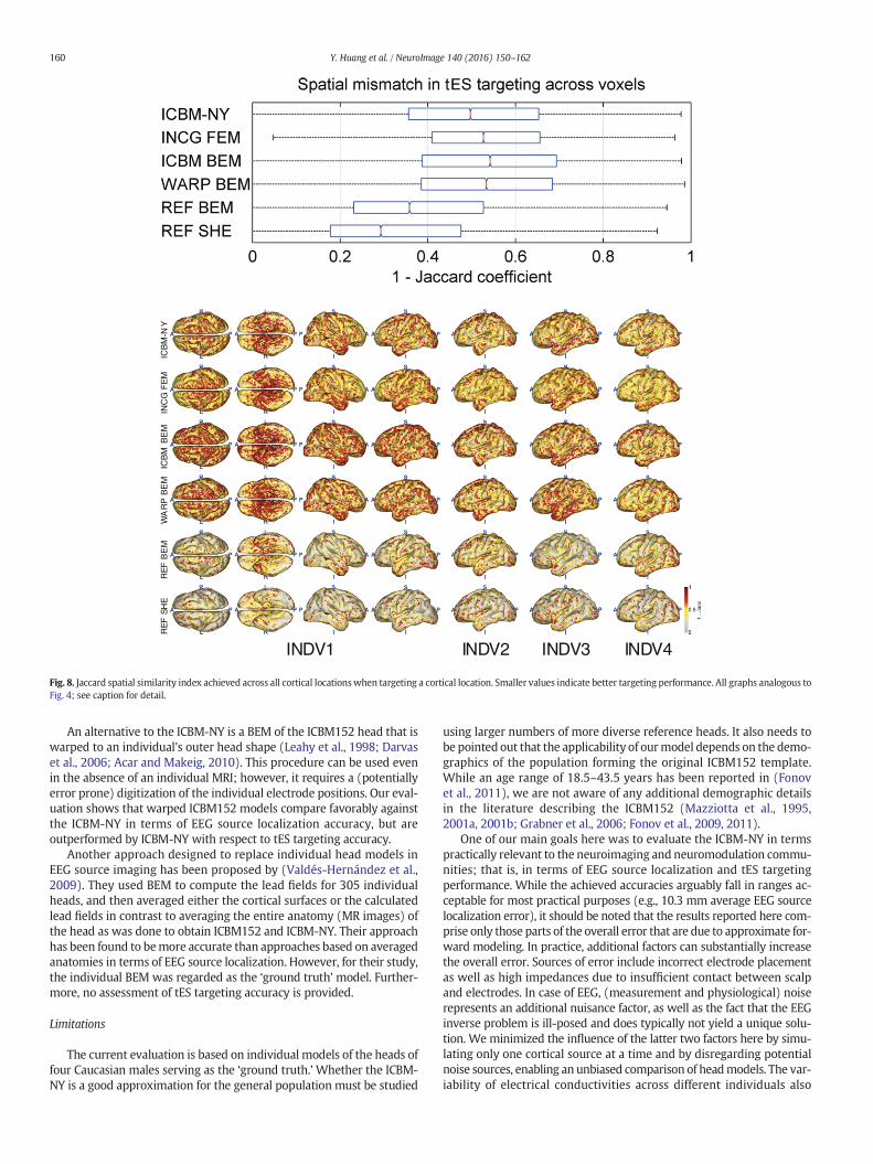
tES targeting accuracy
Figs. 7 and 8 show the results of the tES targeting experiment. ICBM-NY outperforms INCG FEM, ICBMBEM, and evenWARP BEM in terms ofboth the relative error of the achieved electric field intensity at the tar-get and the Jaccard index of peak area distribution similarity. However,similar to what is observed in EEG source localization, ICBM-NYperforms less well than REF BEM and REF SHE, as the latter models ben-efit from knowledge of the reference anatomy, which would requirecostly MR imaging in practice.
Discussion
With theNewYorkHead (ICBM-NY),we intended to create themostaccurate general-purpose electrical volume conductor model possibletoday by integrating the currently most detailed anatomical templatesof the average adult human head with state-of-the-art electrical andcomputational modeling. Our results indicate that the ICBM-NY isindeed highly competitive in terms of EEG source imaging and tEStargeting. According to the performance metrics we evaluated, it out-performs arbitrary reference head models, as well as the relativelywidely used BEM of the ICBM152. This suggests that one should usethe New York Head for targeting and source localization whenever
neither individual MR images nor digitized electrode coordinates areavailable. To facilitate using our model, all required data are madeavailable online in Matlab format.
Relation to the state-of-the-art
There are few software packages in the neuroimaging andneuromodulation communities to date that integrate the ICBM152anatomical template as the reference model. The most commonlyused ‘standard’ head is the Colin27 head (Holmes et al., 1998), in-cluded as a BEM in LORETA (Pascual-Marqui et al., 1994), EEGLAB-NFT (Acar and Makeig, 2010), Brainstorm (Tadel et al., 2011), andFieldTrip (Oostenveld et al., 2011); and as an FEM in COMETS (Junget al., 2013) and BrainStimulator released with SCIRun 5.0 (Institute,2015). Brainstorm added the ICBM152 v2009 (at 1 mm3 resolution) re-cently for boundary element modeling, but similar to Colin27, itsFOV is limited to the brain area. The ICBM-NY, in contrast, employshighly detailed finite element modeling of six tissues including theCSF at 0.5 mm3 resolution. Its FOV moreover covers the entirehead. This extended FOV is important for tES targeting, where it iscommon to place reference electrodes far away from the scalp(Huang et al., 2013).
ICB
M-N
YIN
CG
FE
MIC
BM
BE
MW
AR
PB
EM
RE
FB
EM
RE
FS
HE
INDV1 INDV2 INDV3 INDV4
Fig. 8. Jaccard spatial similarity index achieved across all cortical locationswhen targeting a cortical location. Smaller values indicate better targeting performance. All graphs analogous toFig. 4; see caption for detail.
160 Y. Huang et al. / NeuroImage 140 (2016) 150–162
An alternative to the ICBM-NY is a BEM of the ICBM152 head that iswarped to an individual's outer head shape (Leahy et al., 1998; Darvaset al., 2006; Acar and Makeig, 2010). This procedure can be used evenin the absence of an individual MRI; however, it requires a (potentiallyerror prone) digitization of the individual electrode positions. Our eval-uation shows that warped ICBM152 models compare favorably againstthe ICBM-NY in terms of EEG source localization accuracy, but areoutperformed by ICBM-NY with respect to tES targeting accuracy.
Another approach designed to replace individual head models inEEG source imaging has been proposed by (Valdés-Hernández et al.,2009). They used BEM to compute the lead fields for 305 individualheads, and then averaged either the cortical surfaces or the calculatedlead fields in contrast to averaging the entire anatomy (MR images) ofthe head as was done to obtain ICBM152 and ICBM-NY. Their approachhas been found to bemore accurate than approaches based on averagedanatomies in terms of EEG source localization. However, for their study,the individual BEM was regarded as the ‘ground truth’ model. Further-more, no assessment of tES targeting accuracy is provided.
Limitations
The current evaluation is based on individual models of the heads offour Caucasian males serving as the ‘ground truth.’ Whether the ICBM-NY is a good approximation for the general population must be studied
using larger numbers of more diverse reference heads. It also needs tobe pointed out that the applicability of ourmodel depends on the demo-graphics of the population forming the original ICBM152 template.While an age range of 18.5–43.5 years has been reported in (Fonovet al., 2011), we are not aware of any additional demographic detailsin the literature describing the ICBM152 (Mazziotta et al., 1995,2001a, 2001b; Grabner et al., 2006; Fonov et al., 2009, 2011).
One of our main goals here was to evaluate the ICBM-NY in termspractically relevant to the neuroimaging and neuromodulation commu-nities; that is, in terms of EEG source localization and tES targetingperformance. While the achieved accuracies arguably fall in ranges ac-ceptable for most practical purposes (e.g., 10.3 mm average EEG sourcelocalization error), it should be noted that the results reported here com-prise only those parts of the overall error that are due to approximate for-ward modeling. In practice, additional factors can substantially increasethe overall error. Sources of error include incorrect electrode placementas well as high impedances due to insufficient contact between scalpand electrodes. In case of EEG, (measurement and physiological) noiserepresents an additional nuisance factor, as well as the fact that the EEGinverse problem is ill-posed and does typically not yield a unique solu-tion. We minimized the influence of the latter two factors here by simu-lating only one cortical source at a time and by disregarding potentialnoise sources, enabling an unbiased comparison of headmodels. The var-iability of electrical conductivities across different individuals also

161Y. Huang et al. / NeuroImage 140 (2016) 150–162
contributes to the overall error. Lastly, it should be noted that even the‘ground truth’ model of the reference head (in our case an FEM) is bydefinition only an approximation to the real world and contributes ashare to the global error.
Point-like electrodes (see ##Segmentation and electrode placementsection) are not entirely realistic in the context of tES, where spongepads or high-definition disc electrodes are typically used (Nitsche andPaulus, 2000; Edwards et al., 2013). However, we did not performrealistic electrode modeling here, as our goal was to provide maximalflexibility w.r.t. electrode montage in order to make the ICBM-NY aswidely applicable as possible. Modeling each electrode as a pointallowed us to compute a single lead field for 231 candidate electrode lo-cations covering the entire scalp. By selecting appropriate parts, thatsame lead field can be used for all montages involving subsets of these231 electrode locations. Modeling a disc electrode with conductive gelunderneath each of the 231 candidate locations would artificially in-crease the conductance of the scalp surface, and introduce errors formontages involving fewer than 231 electrodes, which is the defaultcase in tES and even EEG. As an alternative, one might physicallymodel specific electrode montages. However, in order to make such anapproach widely applicable, this would have to be performed separatelyfor each possible electrode montage, which is computationally prohibi-tive. An analysis of one bipolar montage (C4-Iz) shows that the electricfield distribution in the brain obtained from using point-like electrodesonly deviates by 4% from the field obtained using disc electrodes onaverage. It has also recently been shown that one can use an array ofhigh-definition disc electrodes to approximate pad electrodes (Kempeet al., 2014).
Due to lack of diffusion tensor imaging (DTI) data for the ICBM152,we did not include WM anisotropy, nor did we differentiate betweenskull spongiosa and compacta for the ICBM-NYmodel. As aworkaround,one could incorporate anisotropy by registering the diffusion tensorimages of one arbitrary adult individual to the ICBM-NY anatomy. How-ever, the result will be noisy because one individual cannot representthe average WM tractography across 152 subjects in the same way asthe ICBM152 MRI does for the anatomy. Generally, it is still debatablewhether or not WM anisotropy and inhomogeneous skull should be in-cluded in the modeling of EEG and tES. Many studies have shown thatthese two factors can lead to significant changes in the electric field dis-tributions in the brain (Sadleir and Argibay, 2007; Dannhauer et al.,2011;Windhoff et al., 2011; Suh et al., 2012;Wagner et al., 2014). How-ever, a recent study (Vorwerk et al., 2014) shows that explicit modelingof different skull layers might not be necessary especially when anoptimized conductivity value is used, and it is admissible not to includewhite matter anisotropy considering the complexity and limitation ofthe modeling approach (e.g., uncertainties on converting diffusion im-aging data into anisotropic conductivities (Shahid et al., 2013)). Mostimportantly, without validation from experimentally recorded data,no solid conclusion can be made regarding the necessity to modelthese details. Nevertheless, one should add this level of detail in thefuture when DTI data for ICBM152 and reliable modeling approachesbecome available.
Evaluation criteria
The evaluation of tES targeting is sensitive to the orientation of theelectric field at the target. The results presented here are based onmaximizing the electric field along the normal direction of the corti-cal surface at the target. Further experiments show that, if the elec-tric field is maximized without fixing its orientation at the target(i.e., maximizing its magnitude, (Dmochowski et al., 2013)), ICBM-NYperforms better than all the BEMs (REF BEM, REF SHE, WARP BEM,ICBM BEM). The lack of the highly conductive CSF layer in 3-shellBEMs leads rather different current directions on the cortical surfaceas compared to the more realistic FEMs. There, shunting of currents byCSF results in predominant currents in direction normal to cortical
surface. This systematic difference in field orientation introduces abias if the electric field ismaximizedwithout considering its orientationat the target (BEM tends to have stronger fields in radial direction,whereas FEM tends to favour tangential fields). To avoid biases in theevaluation, we here optimized the field along the direction perpendicularto the cortical surface, which is the most physiologically meaningful ori-entation as the specific direction of the field is determined by the localanatomy of the cortex (i.e., radial at gyri and tangential at sulci). Analo-gously, we assumed normal oriented current when simulating sourcecurrents in the evaluation of EEG source imaging. It should be noted,however, that the errormetrics used for tES targeting and EEG source im-aging are invariant to field orientation, as they are computed using thefieldmagnitude and span. Therefore, the variability of the lead fields dueto differing native spaces does not affect the validity of the evaluation.
Conclusions
We presented the New York Head (ICBM-NY), a highly detailedFEM of the average adult human head. The ICBM-NY integrates thecurrently most detailed anatomical templates with state-of-the-artelectrical and computational modeling implementing the guidelinesof (Vorwerk et al., 2014). Our model outperforms reference headmodels of ‘arbitrary’ individuals, as well as a BEM of the ICBM152in terms of source localization and tES targeting accuracy. It is more-over competitive to individualized BEMs in terms of tES targeting ac-curacy. We therefore propose it as a new standard model for tEStargeting and EEG source localization whenever an individual MRIis not available. All model data are made available online in Matlabformat to facilitate broad adoption.
Acknowledgments
This work was supported by a Marie Curie InternationalOutgoing Fellowship (grant no. PIOF-GA-2013-625991) within the 7thEuropean Community Framework Programme, and a DARPA GrantW911NF1410408. We thank Dana Brooks, Carsten Wolters, AlexandreGramfort, Guido Nolte, Marom Bikson, Moritz Dannhauer, and DanielMiklody for fruitful discussions.
References
Acar, Z.A., Makeig, S., 2010. Neuroelectromagnetic forward head modeling toolbox.J. Neurosci. Methods 190, 258–270.
Akalin Acar, Z., Makeig, S., 2013. Effects of forward model errors on EEG source localiza-tion. Brain Topogr. 26, 378–396.
Ashburner, J., Friston, K.J., 2005. Unified segmentation. NeuroImage 26, 839–851.Aubert-Broche, B., Evans, A.C., Collins, L., 2006. A new improved version of the realistic
digital brain phantom. NeuroImage 32, 138–145.Baillet, S., Mosher, J., Leahy, R., 2001. Electromagnetic brain mapping. IEEE Signal Process.
Mag. 18, 14–30.Collignon, A., Maes, F., Delaere, D., Vandermeulen, D., Suetens, P., Marchal, G., 1995. Auto-
mated multi-modality image registration based on information theory. Bizais.Collins, D.L., Neelin, P., Peters, T.M., Evans, A.C., 1994. Automatic 3d intersubject registra-
tion ofMR volumetric data in standardized Talairach space. J. Comput. Assist. Tomogr.18, 192–205.
Dannhauer, M., Lanfer, B., Wolters, C.H., Knösche, T.R., 2011. Modeling of the human skullin EEG source analysis. Hum. Brain Mapp. 32, 1383–1399.
Dannhauer, M., Brooks, D., Tucker, D., MacLeod, R., 2012. A pipeline for the simulation oftranscranial direct current stimulation for realistic human headmodels using SCIRun/BioMesh3D. 34th Annual International Conference of the IEEE Engineering inMedicineand Biology Society, San Diego, CA, pp. 5486–5489.
Darvas, F., Ermer, J.J., Mosher, J.C., Leahy, R.M., 2006. Generic head models for atlas-basedEEG source analysis. Hum. Brain Mapp. 27, 129–143.
Datta, A., Bansal, V., Diaz, J., Patel, J., Reato, D., Bikson, M., 2009. Gyri-precise headmodel oftranscranial DC stimulation: improved spatial focality using a ring electrode versusconventional rectangular pad. Brain Stimul. 2, 201–207.
Datta, A., Bikson, M., Fregni, F., 2010. Transcranial direct current stimulation in patientswith skull defects and skull plates: high-resolution computational FEM study of fac-tors altering cortical current flow. NeuroImage 52, 1268–1278.
Datta, A., Truong, D., Minhas, P., Parra, L.C., Bikson, M., 2012. Inter-individual variationduring transcranial direct current stimulation and normalization of dose using MRI-derived computational models. Front. Psychiatry 3, 91.
Dmochowski, J.P., Datta, A., Bikson, M., Su, Y., Parra, L.C., 2011. Optimized multi-electrodestimulation increases focality and intensity at target. J. Neural Eng. 8, 046011.
162 Y. Huang et al. / NeuroImage 140 (2016) 150–162
Dmochowski, J.P., Datta, A., Huang, Y., Richardson, J.D., Bikson, M., Fridriksson, J., Parra,L.C., 2013. Targeted transcranial direct current stimulation for rehabilitation afterstroke. NeuroImage 75, 12–19.
Edwards, D., Cortes, M., Datta, A., Minhas, P., Wassermann, E.M., Bikson, M., 2013. Physi-ological and modeling evidence for focal transcranial electrical brain stimulation inhumans: a basis for high-definition tDCS. NeuroImage 74, 266–275.
Evans, A., Collins, D., Mills, S.R., Brown, E.D., Kelly, R.L., Peters, T., 1993. 3D statistical neu-roanatomical models from 305 MRI volumes. Nuclear Science Symposium and Med-ical Imaging Conference, 1993. 1993 IEEE Conference Record vol. 3, pp. 1813–1817.
Fonov, V., Evans, A., McKinstry, R., Almli, C., Collins, D., 2009. Unbiased nonlinear averageage-appropriate brain templates from birth to adulthood. NeuroImage 47, S102.
Fonov, V., Evans, A.C., Botteron, K., Almli, C.R., McKinstry, R.C., Collins, D.L., BrainDevelopment Cooperative Group, 2011. Unbiased average age-appropriate atlasesfor pediatric studies. NeuroImage 54, 313–327.
Friston, K.J., Ashburner, J., Frith, C.D., Poline, J.B., Heather, J.D., Frackowiak, R.S.J., 1995.Spatial registration and normalization of images. Hum. Brain Mapp. 3, 165–189.
Fuchs, M., Kastner, J., Wagner, M., Hawes, S., Ebersole, J.S., 2002. A standardized boundaryelement method volume conductor model. Clin. Neurophysiol. 113, 702–712.
Geffroy, D., Rivière, D., Denghien, I., Souedet, N., Laguitton, S., Cointepas, Y., 2011.Brainvisa: a complete software platform for neuroimaging. Python in Neuroscienceworkshop, Paris.
Golub, G.H., Van Loan, C.F., 2012. Matrix computations vol. 3. JHU Press.Grabner, G., Janke, A.L., Budge, M.M., Smith, D., Pruessner, J., Collins, D.L., 2006. Symmetric
atlasing and model based segmentation: an application to the hippocampus in olderadults. Medical image computing and computer-assisted intervention: MICCAI… In-ternational Conference on Medical Image Computing and Computer-Assisted Inter-vention 9, pp. 58–66.
Gramfort, A., Papadopoulo, T., Olivi, E., Clerc, M., 2010. OpenMEEG: opensource softwarefor quasistatic bioelectromagnetics. Biomed. Eng. 9, 1–20.
Gramfort, A., Luessi, M., Larson, E., Engemann, D.A., Strohmeier, D., Brodbeck, C.,Parkkonen, L., Hämäläinen, M.S., 2014. MNE software for processing MEG and EEGdata. NeuroImage 86, 446–460.
Griffiths, D.J., 1999. Introduction to electrodynamics. third ed Prentice Hall, Upper SaddleRiver, NJ.
Haufe, S., Nikulin, V.V., Ziehe, A., Müller, K.R., Nolte, G., 2008. Combining sparsity and ro-tational invariance in EEG/MEG source reconstruction. NeuroImage 42, 726–738.
Haufe, S., Tomioka, R., Dickhaus, T., Sannelli, C., Blankertz, B., Nolte, G., Müller, K.R., 2011.Large-scale EEG/MEG source localization with spatial flexibility. NeuroImage 54,851–859.
Holmes, C.J., Hoge, R., Collins, L., Woods, R., Toga, A.W., Evans, A.C., 1998. Enhancement ofMR images using registration for signal averaging. J. Comput. Assist. Tomogr. 22,324–333.
Huang, Y., Parra, L.C., 2015. Fully automated whole-head segmentation with improvedsmoothness and continuity, with theory reviewed. PLoS One 10, e0125477.
Huang, Y., Dmochowski, J.P., Su, Y., Datta, A., Rorden, C., Parra, L.C., 2013. Automated MRIsegmentation for individualized modeling of current flow in the human head.J. Neural Eng. 10, 066004.
Im, C.H., Jung, H.H., Choi, J.D., Lee, S.Y., Jung, K.Y., 2008. Determination of optimal electrodepositions for transcranial direct current stimulation (tDCS). Phys. Med. Biol. 53,N219–N225.
Institute, S., 2015. SCIRun: A Scientific Computing Problem Solving Environment. Scientif-ic Computing and Imaging Institute (SCI) Download from: http://www.scirun.org.
Jaccard, P., 1901. Distribution de la flore alpine dans le bassin des dranses et dansquelques régions voisines. Bull. Soc. Vaud. Sci. Nat. 37, 241–272.
Jones, K.T., Stephens, J.A., Alam, M., Bikson, M., Berryhill, M.E., 2015. Longitudinalneurostimulation in older adults improves workingmemory. PLoS One 10, e0121904.
Jung, Y.J., Kim, J.H., Im, C.H., 2013. COMETS: a MATLAB toolbox for simulating local electricfields generated by transcranial direct current stimulation (tDCS). Biomed. Eng. Lett.3, 39–46.
Kempe, R., Huang, Y., Parra, L.C., 2014. Simulating pad-electrodes with high-definition ar-rays in transcranial electric stimulation. J. Neural Eng. 11, 026003.
Leahy, R., Mosher, J., Spencer, M., Huang, M., Lewine, J., 1998. A study of dipole localizationaccuracy for meg and eeg using a human skull phantom. Electroencephalogr. Clin.Neurophysiol. 107, 159–173.
Marzetti, L., Del Gratta, C., Nolte, G., 2008. Understanding brain connectivity from EEGdata by identifying systems composed of interacting sources. NeuroImage 42, 87–98.
Mazziotta, J.C., Toga, A.W., Evans, A., Fox, P., Lancaster, J., 1995. A probabilistic atlas of thehuman brain: theory and rationale for its development. The international consortiumfor brain mapping (ICBM). NeuroImage 2, 89–101.
Mazziotta, J., Toga, A., Evans, A., Fox, P., Lancaster, J., Zilles, K., Woods, R., Paus, T., Simpson,G., Pike, B., Holmes, C., Collins, L., Thompson, P., MacDonald, D., Iacoboni, M.,Schormann, T., Amunts, K., Palomero-Gallagher, N., Geyer, S., Parsons, L., Narr, K.,Kabani, N., Le Goualher, G., Feidler, J., Smith, K., Boomsma, D., Pol, H.H., Cannon, T.,Kawashima, R., Mazoyer, B., 2001a. A four-dimensional probabilistic atlas of thehuman brain. J. Am. Med. Inform. Assoc. 8, 401–430.
Mazziotta, J., Toga, A., Evans, A., Fox, P., Lancaster, J., Zilles, K., Woods, R., Paus, T., Simpson,G., Pike, B., Holmes, C., Collins, L., Thompson, P., MacDonald, D., Iacoboni, M.,Schormann, T., Amunts, K., Palomero-Gallagher, N., Geyer, S., Parsons, L., Narr, K.,Kabani, N., Le Goualher, G., Boomsma, D., Cannon, T., Kawashima, R., Mazoyer, B.,2001b. A probabilistic atlas and reference system for the human brain: International
consortium for brain mapping (ICBM). Philos. Trans. R. Soc. London, Ser. B 356,1293–1322.
Mendonca, M.E., Santana, M.B., Baptista, A.F., Datta, A., Bikson, M., Fregni, F., Araujo, C.P.,2011. Transcranial DC stimulation in fibromyalgia: optimized cortical target support-ed by high-resolution computational models. J. Pain 12, 610–617.
Mosher, J., Leahy, R., 1999. Source localization using recursively applied and projected(RAP) MUSIC. IEEE Trans. Signal Process. 47, 332–340.
Mosher, J., Leahy, R., Lewis, P., 1999. EEG and MEG: forward solutions for inversemethods. IEEE Trans. Biomed. Eng. 46, 245–259.
Nitsche, M.A., Paulus, W., 2000. Excitability changes induced in the human motor cortexby weak transcranial direct current stimulation. J. Physiol. 527, 633–639.
Nolte, G., Dassios, G., 2005. Analytic expansion of the EEG lead field for realistic volumeconductors. Phys. Med. Biol. 50, 3807–3823.
Oostenveld, R., Praamstra, P., 2001. The five percent electrode system for high-resolutionEEG and ERP measurements. Clin. Neurophysiol. 112, 713–719.
Oostenveld, R., Fries, P., Maris, E., Schoffelen, J.M., 2011. FieldTrip: open source softwarefor advanced analysis of MEG, EEG, and invasive electrophysiological data. Comput.Intell. Neurosci. 2011, 1–9.
Park, J.H., Hong, S.B., Kim, D.W., Suh, M., Im, C.H., 2011. A novel array-type transcranial di-rect current stimulation (tDCS) system for accurate focusing on targeted brain areas.IEEE Trans. Magn. 47, 882–885.
Pascual-Marqui, R.D., Michel, C.M., Lehmann, D., 1994. Low resolution electromagnetic to-mography: a new method for localizing electrical activity in the brain. Int.J. Psychophysiol. 18, 49–65.
Richardson, J.D., Fillmore, P., Datta, A., Truong, D., Bikson, M., Fridriksson, J., 2014. Towarddevelopment of sham protocols for high-definition transcranial direct current stimu-lation (HD-tDCS). NeuroRegulation 1, 62.
Rivière, D., Régis, J., Cointepas, Y., Papadopoulos-Orfanos, D., Cachia, A., Mangin, J.F., 2003.A freely available Anatomist/BrainVISA package for structural morphometry of thecortical sulci. Proc. 9th HBM, New York, p. 934.
Rush, S., Driscoll, D.A., 1969. EEG electrode sensitivity—an application of reciprocity.I.E.E.E. Trans. Biomed. Eng. 16, 15–22.
Sadleir, R.J., Argibay, A., 2007. Modeling skull electrical properties. Ann. Biomed. Eng. 35,1699–1712.
Salvador, R., Mekonnen, A., Ruffini, G., Miranda, P.C., 2010. Modeling the electric field in-duced in a high resolution realistic head model during transcranial current stimula-tion. Conference Proceedings: Annual International Conference of the IEEEEngineering in Medicine and Biology Society. IEEE Engineering in Medicine and Biol-ogy Society. Conference 2010, pp. 2073–2076.
Sarvas, J., 1987. Basic mathematical and electromagnetic concepts of the biomagnetic in-verse problem. Phys. Med. Biol. 32, 11.
Schmidt, R., 1986. Multiple emitter location and signal parameter estimation. IEEE Trans.Antennas Propag. 34, 276–280.
Shahid, S., Wen, P., Ahfock, T., 2013. Numerical investigation of white matter anisotropicconductivity in defining current distribution under tDCS. Comput. Methods Prog.Biomed. 109, 48–64.
Suh, H.S., Lee, W.H., Kim, T.S., 2012. Influence of anisotropic conductivity in the skull andwhite matter on transcranial direct current stimulation via an anatomically realisticfinite element head model. Phys. Med. Biol. 57, 6961–6980.
Tadel, F., Baillet, S., Mosher, J.C., Pantazis, D., Leahy, R.M., 2011. Brainstorm: a user-friendlyapplication for MEG/EEG analysis. Comput. Intell. Neurosci. 2011.
Truong, D.Q., Hüber, M., Xie, X., Datta, A., Rahman, A., Parra, L.C., Dmochowski, J.P., Bikson,M., 2014. Clinician accessible tools for GUI computational models of transcranial elec-trical stimulation: BONSAI and SPHERES. Brain Stimul. 7, 521–524.
Valdés-Hernández, P.A., von Ellenrieder, N., Ojeda-Gonzalez, A., Kochen, S., Alemán-Gómez, Y., Muravchik, C., Valdés-Sosa, P.A., 2009. Approximate average head modelsfor EEG source imaging. J. Neurosci. Methods 185, 125–132.
Vatta, F., Meneghini, F., Esposito, F., Mininel, S., Salle, F.D., 2010. Realistic and sphericalhead modeling for EEG forward problem solution: a comparative cortex-based anal-ysis. Comput. Intell. Neurosci. 2010, 1–11.
Villamar, M.F., Wivatvongvana, P., Patumanond, J., Bikson, M., Truong, D.Q., Datta, A.,Fregni, F., 2013. Focal modulation of the primary motor cortex in fibromyalgiausing 4 × 1-ring high-definition transcranial direct current stimulation (HD-tDCS):immediate and delayed analgesic effects of cathodal and anodal stimulation. J. Pain14, 371–383.
Vorwerk, J., Cho, J.H., Rampp, S., Hamer, H., Knösche, T.R., Wolters, C.H., 2014. A guidelinefor head volume conductor modeling in EEG and MEG. NeuroImage 100, 590–607.
Wagner, T., Fregni, F., Fecteau, S., Grodzinsky, A., Zahn, M., Pascual-Leone, A., 2007. Trans-cranial direct current stimulation: a computer-based human model study.NeuroImage 35, 1113–1124.
Wagner, S., Rampersad, S.M., Aydin, Vorwerk, J., Oostendorp, T.F., Neuling, T., Herrmann,C.S., Stegeman, D.F., Wolters, C.H., 2014. Investigation of tDCS volume conduction ef-fects in a highly realistic head model. J. Neural Eng. 11, 016002.
Windhoff, M., Opitz, A., Thielscher, A., 2011. Electric field calculations in brain stimulationbased on finite elements: an optimized processing pipeline for the generation andusage of accurate individual head models. Hum. Brain Mapp. 34, 923–935.
Wolters, C.H., Anwander, A., Berti, G., Hartmann, U., 2007. Geometry-adapted hexahedralmeshes improve accuracy of finite-element-method-based EEG source analysis. IEEETrans. Biomed. Eng. 54, 1446–1453.