theoferometer for high accuracy optical alignment and ... · theoferometer for high accuracy...
TRANSCRIPT
Theoferometer for High Accuracy Optical Alignment and Metrology
Ronald Tolanda, Doug Levitona, Seth Koterbab
aNASAIGoddard Space Flight Center, Code 551 Optics, Greenbelt, MD 20771 bConcordia College, 901 8th St S., Moorhead, MN 56562
ABSTRACT
The accurate measurement of the orientation of optica l parts and systems is a pressing problem for upcoming space missions, such as stellar interferometers, requiring the knowledge and maintenance of positions to the sub-arcsecond level. Theodo lites, the devices commonly used to make these measurements, cannot provide the needed level of accuracy. This paper describes the design, construction, and testing of an interferometer system to fill the w idening gap between future requirements and current capabi lities. A Twyman-Green interferometer mounted on a 2 degree of freedom rotation stage is able to obtain sub-arcsecond , gravity-referenced ti It measurements of a sample al ignment cube. Dubbed a 'theoferometer,' this device offers greater ease-of-use, accuracy, and repeatability than conventional methods, making it a suitable 21 st-century replacement for the theodol ite.
1. INTRODUCTION
Vector metrology plays a vital role in the assembly of space instrumentation and spacecraft. For NASA flight optical instrumentation, the relation of a detector to a mirror, the placement of an optical bench inside an enclosure, and accounting for the deflection of a weighted structure under gravity all require opto-mechanical metrology. Science goals and mechanical tolerances are both made poss ible by the measurements conducted with theodolites, tilt levels, and laser trackers .
Vector metrology is the measuring of the pointing direction of the surface normal vector of one face ofa reflective (a lignment) cube. This measurement is usually performed with a theodol ite-a telescope equipped with a lamp and interna l reticule, set on a stage able to rotate vertically (elevation) and along the horizon (azimuth) . With the foc us of the te lescope set to infinity and the lamp on, the telescope sends out a collimated reticule image, which can be reflected off the face of an alignment cube and re-imaged through the telescope to produce a second visible reticule alongside the origina l. A user can then, looking through the telescope, adjust the azimuth and e levation orientation of the telescope until the two reticu les overlap. In this condition, the pointing direction of the telescope is anti-parallel to the cube surface . Thus, knowing the orientation of the te lescope in azimuth and elevation-the latter measured with respect to the local gravity vector-gran ts knowledge of the orientation of the cube face surface normal vector in those two directions.
A single measurement is oflimited utility; usually, many cubes are measured on a spacecraft by several theodolites. For instance, placing two theodolites to look at the same cube-each looking at a different side-measures the orientation of the cube in 3 degrees of freedo m. Figure 1 illustrates this principle. Each theodolite measures the azimuth and elevation fo r its respective cube face. The two theodolites are then bores ighted together-point each at the other-and record this azimuth reading. Using trigonometry, one can now relate the azimuthal readings of the two cube faces to each other, and the elevation reading for each face gives the third degree of freedom.
https://ntrs.nasa.gov/search.jsp?R=20040171194 2018-06-08T20:45:52+00:00Z

.~
THEODOLITE 1
o
THEODOLITE 1
THEODOLITE 2
Vector metrology --Lookl ng at cube
Azimuth rotaton in pl ane of page Elevation r otation normal to page
THEODOLITE 2
Vector metrology --boresi ghting
Figure 1: Vector Metro logy Example
This can be done with several cubes placed about a spacecraft . If each new theodolite is boresighted to a single ' primary' theodolite, each cube is thereby related to every other cube. With all the cube orientations related to each other, one can bui ld a coordinate system for the spacecraft based on the fi rst (master reference) cube readings . Tfthe spacecraft were then removed, the setup broken down then rebuilt, and the measurements retaken, one could build the same coordinate system, and compare the new measurements directly to the old . Note that w ithout relating all the cube readings to a single master reference, there is no way to compare cube readings between setups, because on ly the elevation reading of a theodolite is measured with respect to some constant- gravity- the azimuthal angle is arbitrary. The construction of coordinate systems fro m relat ing cube faces is what ascertains if a spacecraft component shifts during vibration testing or twists as other components are added or changed.
Naturally, there is an uncertainty associated with each cube measurement. There is error in the know ledge of the gravity vector, error due to v ibration of the test artic le, error from the optics in the telescope, error from the operator who must decide how close ly the reticules must overlap for the theodol ite to be considered well-aligned . Under normal lab conditions, these errors add up to a two arcsecond uncertainty per cube face measurement. As more measurements are made, more theodo lites related to each other, the total uncertainty for knowing where a particular cube is re lative to the others grows. This uncertainty can be lowered somewhat through mUltiple measurements and statistical analysis, but the costs in time and manpower associated w ith such procedures becomes prohibitive past a certain level. For projects that requ ire knowledge of part orientation to the arcsecond or sub-arcsecond level, theodolites cannot perform to the level required.
A new method for performing vector metrology is needed, one w ith a much lower uncertainty to meet present and future needs. This paper outlines such a method, using interferometry. By placi ng a Twyman-Green interferometer l on a stage rotati ng in azimuth and elevation, with position readout v ia high-accuracy optical encoders and measuring vector tilts through automated fr inge analysis, we e liminate many of the sources of error in a theodolite. The goal was to demonstrate a system capable of cube measurements with a 0.1 arcsecond uncertainty or better. The risks inherent in this approach, the so lutions formu lated, and the results of the testing of the completed prototype instrument, dubbed the " theoferometer," are described below.

2. CHALLENGES
Several obstacles revealed themselves early in the investigation. Fi rst and foremost was the problem of support and stability. A structure that sagged more than the 0.1 arcsecond goal would invalidate the results, unless carefully accounted for. Similarly, vibration, if rampant in the theoferometer itself, would prevent it from reaching 0.1 arcsecond uncertainty levels, if the instrument moved more than that between shots. In addition, this structure had to maintain this stiffness and stabil ity whi le rotating the interferometer in 2 degrees of freedom and be able to be leveled (i .e., the az imuthal rotation axis is adjusted to be parallel to the local gravity vector) . Size and weight were other factors to consider, as ultimately the theoferometer would be taken out of the development lab and into a true measurement environment.
Second, how to test such an instrument? When trying to build something better than what has come before, how do you demonstrate that it is, in fact, better? A method was needed to prove the theoferometer's sensitivity, repeatability, and total uncertainty was an improvement upon the theodolite ' s ab ilit ies, which required a testing apparatus better than we wanted the theoferometer to be. As part of the buildup process, the structure needed to be leveled (and the elevation axis gravity referenced) to better than 0.1 arcseconds, and the orthogonality of the 2 axes of rotation (azimuth and elevation) certified to the same degree of accuracy. The grav ity reference was required to give an absolute reference to one of the angles of measurement- this allows a common point of reference between data sets of the same structure in different labs and setups . Orthogonality is important to ensure motion occurs in only one axis at a time, to make certain the theoferometer is only rotating in azimuth when we ask it to rotate horizontally, and not tilting slightly in elevation as we ll.
A third problem was that of fr inge interpretation. The idea that the tilt of a mirror in one (test) leg of an interferometer relative to the mirror in the other (reference) leg causes a certa in fr inge pattern when the beams recombine is wellknown2
. However, the best method of extracting that information, and a way of explicitly tying the physical tilt of a mirror to the number of fringes seen, is not certain. We chose the Fourier transform method of fringe analysis for its robustness and ease in implementation2
•3
•4
, and developed a formu la to convert fringe frequency information calculated via Fourier analysis into phys ical ti lt information at the test mirror. Our algorithm is explained in greater detail elsewhere5
.
3. OPTO-MECHANICAL DESIGN
The actual optical layout is stra ightforward , as illustrated by Figure 2. To save space-and thus weight-we mount the spatial fi lter and beam coll imation assemblies directly onto the laser head. The co ll imated beam passes through a non-polarizing beamspl itter on its way to the alignment cube serving as the reference surface and the cube under test. The return beams are re-combined at the beamsplitter and sent to the CCD via a fo ld flat, again used to make the design as compact as possible.
The cha llenge lay in the mechanica l layout: how to get all the parts, with the requisite degrees of freedom to align them, into a space smal l enough and light enough to be supported by an ai r bearing. The problem was solved by using a layered design and the fact that proper ali gnment required the beamsplitter to be aligned to the laser, then everything else aligned to the beamsplitter to cut back on the number of stages needed, as shown in Figure 3. A single translation stage moves the beamsplitter, reference
TbSTClIBE
FOLD FLAT
CCD
BEA MSI'Ll'ITER
REFERENCE CUBE
-l-__ --j-SPATIAL FILTER OPTICS
LASER
cube, and fold flat, easing re-a lignments to the laser. Figure 2: Simplified Optical Layout of Twyman-Green Interferometer

Each cube sits on a slotted mount that can be moved in one degree of freedom and then clamped down by screws, allowing some fine adjustment orthogonal to the translat ion stage's direct ion of motion. The entire interferometer assembly fits on an aluminum plate only 12" long by 10" w ide.
BEAMSPLITTER
Figure 3: Interferometer Layout
Cylindrical air bearings coupled to linear inchworm motors actuate the theoferometer. The air bearings provide nearly error-free rotation, being almost frict ionless with little runout. The inchworm motors have a 4 nm step size that, when coupled to the air bearings usi ng a 6" long shaft, g ive us the abi lity to rotate the theoferometer in 0.06 arcsecond increments. Figure 4 shows one of the air bearings, and Figure 5 is a photo of one of the inchworm motors in its mount.
Figure 4: Air Bearing Figure 5: Inchworm motor in mount

-. level the azimuth air bearing, we designed a tip/tilt system
Figure 6: Inchworm with clamp ring around bearing extension.
The air bearings are held in place by three mounting screws in the bottom of the housing. Loads are bolted into the top of the rotating shaft. To attach the inchworm motors to the bearings, we designed an extension for the rotating shaft, mounted opposite to the load bearing end. The inchworm motor is coupled to the bearing by a "clutch arm": the motor pushes on an aluminum bar attached to a clamp ring around the bearing shaft extension. Clamping the ring around the extension engages the inchworm as the primary means of rotating the bearing (fine motion), unclamping the ring allows the bearing to rotate freely with the push ofa hand (coarse motion). Figure 6 shows the setup.
In addition to the rotational degrees of freedom offered by the bearings themselves, we also needed to be ab le to level the interferometer plate. We decided to split this job in two parts: one part done in the azimuth air bearing stage, the other in the structure holding the elevation bearing. To
from two plates joined by three pairs of screws: one locking, one adjusting. The azimuth bearing bolts into the top plate, and the who le plate-and everything sitting on top of it-can be tilted in two axes via the adjustment screws, then held in place with the locking screws6 For the elevation stage, a large version of a sine plate was designed. Two plates are joined by a hinge, and separated by a micrometer attached to the top plate and pushing against the bottom. These two plates rest on top of the azi muth bearing's rotating shaft, and the elevation stage bolts directly to the sine plate. This a llows us to adjust the angle between the elevation and azimuth bearings' axes of rotation, crucial if they are to be orthogonal as required.
Crucial to the achievement of a low error design are the optical encoders employed on both axes. These encoders were developed at NASAlGSFC and are described in detail in several papers7
,8,9. Briefly, a CCD images a pattern offiducials and code bits imprinted on a si licon disk mounted to the air bearing shaft extension. The code bits indicate the (sequential) number of the fiducial below. The fiducials are evenly spaced in a ring about the center of the disk. Figure 7 shows a sample encoder image. By knowing the pitch, or spacing, of the fiducials, we can assign an angular value to each fiducial; for example, if fiducial 1 is at 0 degrees, and if each fiducial is 0.5 degrees apart, then fiducial 15 would mark 7.5 degrees. In each image, at least three fiduc ials are visible, allowing us to ca lculate the angular position at the center of the image- the position reported by the encoder software.
Figure 7: Sample Encoder Image
For insurance against encoder errors caused by bearing runout, the encoder disk is imaged at two different locations, spaced 180 degrees apart. Any runout error will be equal for each location but of opposite sign, and can then be taken out of the final position calculation.

Each CCD is bonded in one end of a " read head" mount. An aspheric lens epoxied into a threaded tube at the other end images the encoder disk, with the tube prov id ing focus adjustment (see Figure 8) . This readhead in turn is held by a clamp ring attached to a post inserted into a th rough ho le in a larger cylinder. A similar device holds the LED "flash" in place. Figure 9 shows the read head mounted above the encoder d isk, with the LED on the opposite side to provide illumination. This configuration a llows the camera to be adjusted laterally, rotationally, and in focus to give the best image of the encoder disk.
Figure 8: Encoder Readhead Figure 9: Encoder disk with readheads
4. CONSTRUCTION
Construction of the theoferometer prototype proceeded over several months as parts came in from vendors and were fabricated by machinists. Severa l flaws in the origi nal design were discovered; some were correctable, others will have to wait for a future version. The majority of the design, however, has proven to be sound, and the completed unit works as intended.
One design oversight discovered while building the theoferometer concerned the center of gravity of the various stages. If the center of gravity ofthe interferometer stage d id not lie along the axis of rotation of the elevation bearing, two effects would occur: first, the stage would swing like a pendulum after every rotation, and second, when tilted too far in either direction, the stage would tip over of its own accord. If the elevation stage were not balanced as it spun on the azimuth bearing, the entire stage would wobble. Luckily, the addition of weights to the interferometer and elevation stages corrected both of these prob lems.
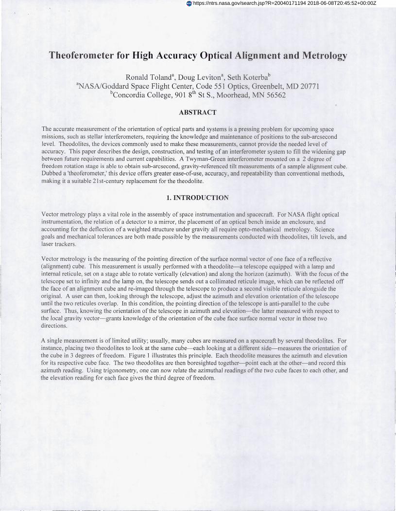
A second design flaw became apparent when we attempted to align the encoder camera readheads to the encoder disk. The performance of the encoder software is very sensitive to the quality of the image it receives; ifit is out of focus, or the fiducials are not perfectly vertica l, it w ill give incorrect readings or none at all. The mounts, as designed, allowed adjustment of the needed degrees of freedom, but not separate ly: loosening the mount to adjust the camera in focus would also free the camera to rotate and til t with res pect to the disk. As the readheads are small, and with little space to reach in and adjust them (see Figu re 12), read head alignment is a tedious process of slight adjustments made with but the loosening and t ightening of a single screw. We were able, through much trial and error, to get all of the readheads aligned; a re-design will decouple the various degrees of freedom-focus, tip/tilt, translation along the plane of the disk-needed for proper alignment.
LOWER STAGE
Figure 12: Tight spacing under theoferometer to access encoder readheads
However, when all was aligned, the encoders performed very well. With no vibration isolation, they showed a precision of +/- 0.00001 degrees, or 0.036 arcseconds. As a preliminary check, each axis was moved a given number of inchworm sub-steps, and the encoders read out to verify they saw the correct amount of rotation . This is a significant achievement for such a (in principle) simple system, and was encouragement that the system might, in fact, be able to accomplish the goal of 0.1 arcseconds total uncertainty.
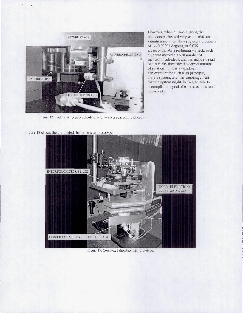
Figure 13: Completed theoferometer prototype.

5. TESTING
Testing of the completed theoferometer was divided into three stages: sensitivity testing, gravity reference/orthogonality test ing, and a comparison test.
(
SMALL ANGLE GENERATOR
Figure 14: Sensitivity Testing with Small Angle Generator Setup
For sensitivity testing, a small angle generator calibrated to 0.01 arcseconds over a 200 arcsecond range was used. A smal l angle generator is simply a mirror mounted on a stage connected to two sine bars. Motion of the sine bars via micrometers at the end far fro m the mirror then causes small angular tilts of the mirror about one or two axes, according to the length of the sine bar and the di stance the micrometer moved through. After setting up a pentaprism and fold flat to al low the test beam to reach the small angle generator's mirror (see Figure 14), the orientation of the mirror was set such that it was approximately 30 arcseconds away from null in each ax is. The mirror was then rotated in both axes by small increments of 1 arcsecond over a 25 arcsecond range, with interferograms acquired at each point for analysis. Comparison of the software-ca lculated tilt values with the true motion of the small angle generator showed how sensitive the theoferometer was to small changes in vector orientation. This error also gives the uncertainty in a theoferometer measurement due to vibration, software errors, and structural stability. The results are illustrated in Figure 15.

l _____ _
Sensitivity Testing Results
Ca lculated Tilt ( a rcsec)
Figure 15: Resu lts of Sensitivity Testing using Small Angle Generator
The data show all error values to be conta ined within a sub-arcsecond spread-the largest error value is approximately 0.7 arcseconds. The errors in the ca lcu lated elevation t il t values show a tighter spread and are generally lower than the azimuth va lues, which can be attr ibuted to the difference in CCD resolution in the horizontal and vertical directions. The average errors across this 25 arcsecond range come to 0.3608 arcseconds in azimuth, and 0.2338 arcseconds in elevation. This confi rms the ability of the theoferometer to make measurements in a real world setting-in terms of vibration-with a sensitivity three times lower than a theodolite. As a preliminary measure of uncertainty, this measurement places a lower bound of - 0.3 arcseconds in the errors in the theoferometer structure, software, and those due to vib ration and imperfections in the test and reference min ors.
The comparison test had not been performed as of the t ime th is paper was written. The plan is to re-calibrate a metrology cube that has already been ca librated by a theodolite. Wh ile this will limit the fidelity of the test to the uncertainty of the theodolite, it will serve as a direct comparison with an accepted metrology tool, and demonstrate the utility of the new instrument in a ro le tradi t ionally ass igned to theodolites. Cube calibration is done to relate the faces (all of the five reflective sides, that is) of the alignment cube to each other before it is attached to a structure to be tested. This allows the non-orthogona li ty of the faces to be taken into account when building a coordinate system. The normal method is to set a theodolite to look at a cube mounted on an U ltradex table, which provides 0.1 arcsecond precis ion rotations, then autocollimate off each face in tu rn, recording the reading of both the theodolite and Ultradex table for each face. The same method is planned fo r calibrating the cube using the theoferometer, after raising the test cube to the appropriate height or us ing a pentaprism and fo ld fla t setup akin to that used for the sensitivity testing.
A gravity reference test had also not yet been performed at the ti me this paper was prepared. The theoferometer pointing direction will be related to the grav ity vector us ing a mercury level and a pentaprism. A mercury level is simply a pool of mercury in an airtight conta iner. The surface of any unconstrained liquid is orthogonal to the local gravity vector; with mercury's high reflectivity, a pool of mercury becomes a near-perfect gravity reference. Placing a pentaprism, which deviates any incoming beam by 90 degrees, above the mercury level should allow the theoferometer to get interference fringes off of the surface of the poo l. A null interferogram thus indicates the theoferometer is pointing along the

horizontal; record ing the elevation reading from the encoders when it is 30 arcseconds from null will provide the needed gravity reference.
This setup will also be used to check the orthogonality of the two rotation axes. After getting a gravity reference, the theoferometer is scanned back and forth in elevation, and the tester watches for a change in the azimuth ti lt present in the interferogram. If the e levation axis of rotation points normal to gravity, no change will be seen. However, if the elevation axis of rotation is til ted with respect to gravity- i.e., it is not orthogonal to the leveled azimuth axis-rotating the theoferometer in elevation will change its relation to the mercury pool in azimuth and elevation, thus causing the ti lt in the interferogram to change in both directions . The tilt of the elevation stage can then be adjusted (and, if necessary, the level of the azimuth stage) until no change is seen in azimuth tilt when rotating the theoferometer in elevation. It is then known that both the theoferometer has been leveled and the orthogonality of its rotation axes verified, to the accuracy of the theoferometer. This test will be performed along with the gravity reference check at a later date.
6. CONCLUSIONS
Even without all the test data in , there are several conclusions that can be drawn from the work performed so far. First, the abil ity of the optical encoders to obtain reasonable data with adequate precision under our conditions of operation (that is, with no vibration isolation) has been demonstrated . This was an essential element of success-without the abi li ty to accurately read the theoferometer's position, the fringe analysis software's sensitivity would be in vain. Second, it was verified that, aga in under conditions of significant vibration, the theoferometer has a sensitivity-0.3 arcseconds-significantly better than a theodolite.
It is believed that comprehens ive testing will confirm the ability of th is prototype to make gravity-referenced vector measurements with an uncerta inty of less than an arcsecond. This is greater than the project goal of 0.1 arcseconds, but several factors point to an eventual attainment of that goal. First, the software itself tested as having an uncertainty of 0. 1 arcseconds or better across several tilt values5
. This means that the majority of the errors in the real-world measurements are due to the environment (vibration) or the structure ofthe theoferometer itself (stability); we have only to mitigate those errors to ach ieve the 0.1 arcsecond limit of our software. Second, the unusual size of the prototype unit forced all testing apparatus to be raised far above the height of the table and insecurely held, exacerbating any vibration levels already present. In most actua l vector metro logy situations, the test part is stably supported at a more moderate height. Third, the resolution of the theoferometer is limited by the resolution of the CCO used to capture the interferograms; while a modest camera served for this prototype, a better camera would undoubtedly lower the uncertainty in tilt measurements and bring us closer to the limits of the software. Finally, even errors in our knowledge of the laser beam diameter and small instabilities in the inchworm motors contribute to our overall uncertainty, errors which can (and will) be remedied in a later model. Thus, though the design may require some modifications to lower the uncertainty, the theoferometer has been shown to be a valid and potentially far superior method for vector metrology.
Several improvements have already been proposed to the current design . A diode laser available with a coherence length of 50 m would drastically lower our weight and size. A reduced interferometer platform weight and length would reduce the stiffness req uirements for the structure, making it lighter and more portable. The current air bearings perform well, but limit the theoferometer's usefulness to laboratories where a ready supply of dry, pressurized air can be found; use of high-quality mechanical bearings, and multiple encoder read heads to compensate for runout errors, should make the theoferometer very portable without sacrificing too much accuracy. And of course, the design for the encoder readheads needs to be revised to make alignment to the encoder disk easier.
With many of the project goals already accomplished, and the theoferometer a working reality, we look forward to completing the prototype's test ing, thus further characterizing its performance, and beyond, as new theoferometer designs move beyond the prototype stage and become ready for commercialization and production as a new, more accurate, vector metrology too l.

ACKNOWLEDGEMENTS
The authors would like to thank the fo llowing people fo r their support, advice, and encouragement during this process, and their participation therein: Henry Sampler, Lou Worrel, Brad Frey, Kevin Redman, Eric Mentzel!, Joe McMann, Julie Crooke, Dave Content, Bruce Dean, and Peter Maymon
REFERENCES
l. D. Malacara, "Twyman-Green Interferometer," Optical Shop Testing, D. Malacara, ed ., pp. 51-94, John Wiley and Sons, New York, 1992
2. D. Malacara, M. Servin, and Z. Malacara, lnterferogram AnalYSis/or Optics Testing, Chap. 8, Marcel Dekker, New York, 1998
3. M. Takeda, H. Ina, and S. Kobayashi, "Fourier-transform method of fringe-pattern analysis for computer-based topography and interferometry," J. Opt. Soc. Am. 72, pp. 156-160, 1981
4. Press et. aI. , Numerical Recipes in Fortran, Chap. 12&13, Cambridge University Press, New York, 1996 5. R. Toland, "Absolute Measurement of Tilts via Fourier Analysis ofInterferograms," SPIE Proceedings, Aug
2004 6. A. Ahmad, "Adjustment Mechanisms," Handbook ojOptomechanical Engineering, A. Ahmad, ed., pp. 211-
253, CRC Press, New York, 1997 7. D. Leviton, "Absolute pos ition encoders using pattern recognition," NASA Tech Briefs 24, p. 6a, June 2000 8. D. Leviton and M. Garza, "Recent advances and applications for NASA 's new, ultra-high sensitivity, absolute,
optical pattern recogni tion encoders," SPIE 4091, pp . 385-394, 2000 9. D. Leviton, " Image process ing fo r new opti cal pattern recognition encoders," SPIE 4113 , pp. 32-40,2000