theolt rtheolt r8 888 user guide user guide & & … r822 user manual.pdftheolt rtheolt r8...
TRANSCRIPT

TheoLt rTheoLt rTheoLt rTheoLt r8888 User Guide User Guide User Guide User Guide
& & & & Operators Operators Operators Operators ManualManualManualManual
forforforfor Surveying in AutoCADSurveying in AutoCADSurveying in AutoCADSurveying in AutoCAD &&&&
BricscadBricscadBricscadBricscad
2 TheoLt R8 Manual AutoCAD A5_en r8.20.docLast printed 27/07/2011 10:28:00 Copyright Latimer CAD Ltd 2010
CONTENTSCONTENTSCONTENTSCONTENTS
General 4 Arc to line 49
Installation & Authorisation 5 Outline wall 50
Configuring for first use 7 Points on a line 52
Trouble-shooting the system 10 Fit to brace 53
Quick start 11 Measure brace &fix 54
Suggested start-up procedure 12 Fit closed 55
Projects in TheoLt 17 Close and distribute 56
Control Tab 19 Close 2 walls / Edit wall length 57
Default orientation 20 Fixed point/ Fixed line 58
Reference orientation 23 Join walls/ Draw Brace 59
Resection 24 Layer Group 60
Position Verification 25 Room Manger 61
Control Station list 26 Plan builder 63
Adjusted Network Control 27 Working with blocks and features 64
Traversing with TheoNetAdjust: Field procedure 31 Customising features for use with DistToPlan 70
Importing control 34 The view tab 74
Draw tab 35 3D views in AutoCAD for façade survey 75
The history panel 36 Two point intersection 76
Working with DistToPlan arx tools 37
DistToPlan Commands 38
Sketch &Measure 39
Rectangular room 42 Appendix 1: TheoLt settings 79
Align 43 Appendix 2: DistToPlan Command list 82
Roomplan 44 Appendix 3: TheoLt and DistToPlan layers list 85
Square feature 48 Appendix 4: TheoLt Core Supported Instruments 87

TheoLt R8 Manual AutoCAD A5_en r8.20.docLast printed 27/07/2011 10:28:00 Copyright Latimer CAD Ltd 2010 3
Formatting: Formatting: Formatting: Formatting: fontfontfontfont ColourColourColourColour LLLLine spaceine spaceine spaceine space
Display text Din light 10pt plain Auto Black single
Plain text Din light 10pt plain Auto Black 13pt
Lists Din light 10pt plain Auto Black single
Indent single tab, no mark
Section Headings Din light 12pt bold Dark Blue single
Sub Headings Din light 10pt bold Auto Black 13pt
Title Din light 24pt bold Dark Blue 27pt
Footer Din Light 6pt plain Auto Grey 9pt
Command line text Courier New 6pt plain Auto Black single
Machine commands As plain text in square brackets
Notes Din light 10pt italic Auto Black 13pt
This page is left intentionally blankThis page is left intentionally blankThis page is left intentionally blankThis page is left intentionally blank

4 TheoLt R8 Manual AutoCAD A5_en r8.20.docLast printed 27/07/2011 10:28:00 Copyright Latimer CAD Ltd 2010
GeneralGeneralGeneralGeneral TheoLt provides an interface between survey measurement tools and a CAD platform for the purpose of achieving survey tasks in CAD. Depending on user options
TheoLt is supplied with themed suites of AutoCAD custom commands for use in the preparation of survey. The tool-sets are designed to enhance the effectiveness of
AutoCAD as both a draughting tool and as a data collection platform for TST and Disto® measurement. The commands make use of existing practice in measurement
as far as possible so that when adapted for a given measurement sequence repeated sets can be deployed. The insertion of scaleable doors, windows, height
annotation and area information (in TheoLt Building Survey for example) all use automated layer management to maximise the editing scope when presenting data. The
procedures for orientation, resection and instrument controls are carried out by the base module: TheoLt core. Familiarisation with how TheoLt core handles raw
survey data is recommended before making use of the extended functions.
TheoLt Product RangeTheoLt Product RangeTheoLt Product RangeTheoLt Product Range The TheoLt CAD survey tool set is available in the following forms. Each component requires separate authorisation. A single installation will load the components
which are activated by authorisation.
1. TheoLt CoreTheoLt CoreTheoLt CoreTheoLt Core: TST and Disto Instrument and CAD interface for AutoCAD, AutoCAD Lt, IntelliCAD and Bricscad with full orientation, data logging and basic 3D
drawing functions.
2. TheoLt ProTheoLt ProTheoLt ProTheoLt Pro: as core but with least squares network adjustment, robotic control and contour modules
3. DistToPlan BasicDistToPlan BasicDistToPlan BasicDistToPlan Basic: a minimum tool set for building survey with the Disto.
4. TheoLt Building surveyTheoLt Building surveyTheoLt Building surveyTheoLt Building survey (TBS) : as core but with DistToPlan tools for AutoCAD and Bricscad
5. TheoLtTheoLtTheoLtTheoLt Buildi Buildi Buildi Building survey Pro : ng survey Pro : ng survey Pro : ng survey Pro : as pro but with DistToPlan tools for AutoCAD and Bricscad
6. TheoLt DistToPlanTheoLt DistToPlanTheoLt DistToPlanTheoLt DistToPlan: as TBS but for Disto only
7. TheoLt ContourTheoLt ContourTheoLt ContourTheoLt Contour: 3d contour and surface generation for AutoCAD/Bricscad
8. TheoOffice:TheoOffice:TheoOffice:TheoOffice: Post process GSI tool set for AutoCAD, AutoCADLT, IntelliCAD and Bricscad
TheoLt R8 Manual AutoCAD A5_en r8.20.docLast printed 27/07/2011 10:28:00 Copyright Latimer CAD Ltd 2010 5
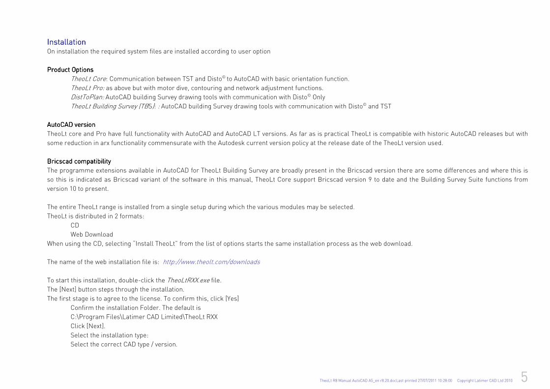
InstallationInstallationInstallationInstallation On installation the required system files are installed according to user option
Product OptionsProduct OptionsProduct OptionsProduct Options
TheoLt Core: Communication between TST and Disto© to AutoCAD with basic orientation function.
TheoLt Pro: as above but with motor dive, contouring and network adjustment functions.
DistToPlan: AutoCAD building Survey drawing tools with communication with Disto© Only
TheoLt Building Survey (TBS): : AutoCAD building Survey drawing tools with communication with Disto© and TST
AutoCAD versionAutoCAD versionAutoCAD versionAutoCAD version
TheoLt core and Pro have full functionality with AutoCAD and AutoCAD LT versions. As far as is practical TheoLt is compatible with historic AutoCAD releases but with
some reduction in arx functionality commensurate with the Autodesk current version policy at the release date of the TheoLt version used.
Bricscad compatibilityBricscad compatibilityBricscad compatibilityBricscad compatibility
The programme extensions available in AutoCAD for TheoLt Building Survey are broadly present in the Bricscad version there are some differences and where this is
so this is indicated as Bricscad variant of the software in this manual, TheoLt Core support Bricscad version 9 to date and the Building Survey Suite functions from
version 10 to present.
The entire TheoLt range is installed from a single setup during which the various modules may be selected.
TheoLt is distributed in 2 formats:
CD
Web Download
When using the CD, selecting “Install TheoLt” from the list of options starts the same installation process as the web download.
The name of the web installation file is: http://www.theolt.com/downloads
To start this installation, double-click the TheoLtRXX.exe file.
The [Next] button steps through the installation.
The first stage is to agree to the license. To confirm this, click [Yes]
Confirm the installation Folder. The default is
C:\Program Files\Latimer CAD Limited\TheoLt RXX
Click [Next].
Select the installation type:
Select the correct CAD type / version.
6 TheoLt R8 Manual AutoCAD A5_en r8.20.docLast printed 27/07/2011 10:28:00 Copyright Latimer CAD Ltd 2010
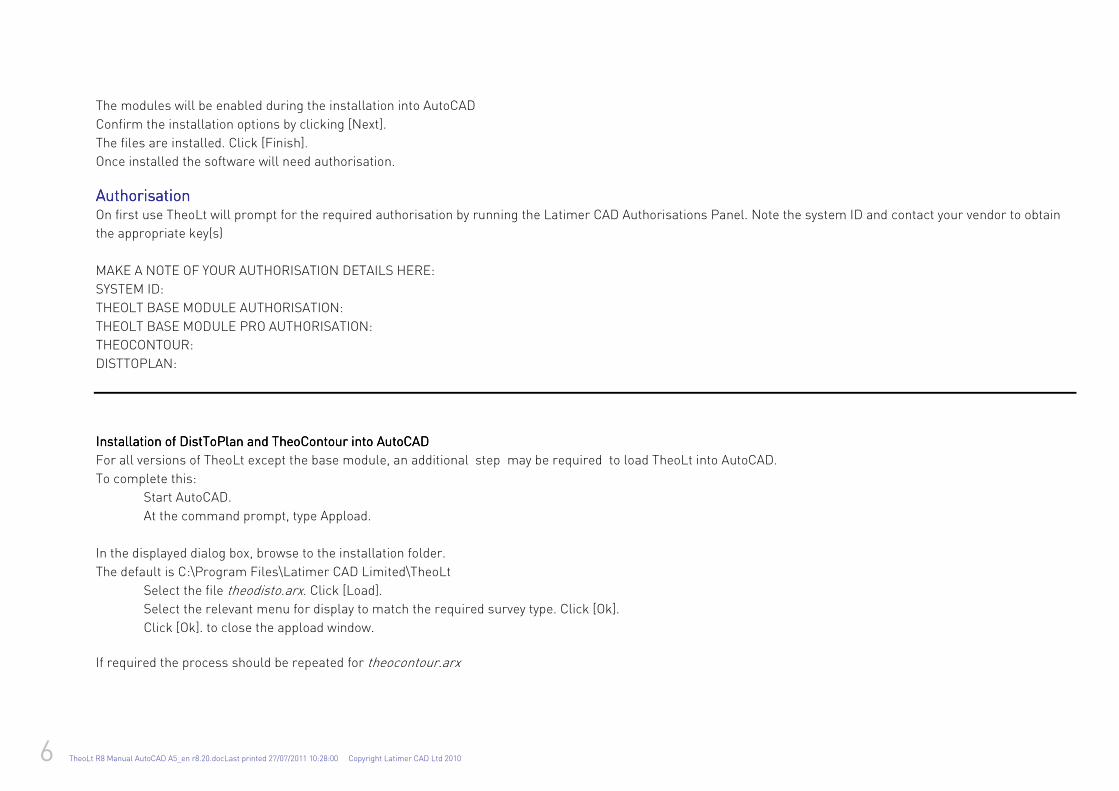
The modules will be enabled during the installation into AutoCAD
Confirm the installation options by clicking [Next].
The files are installed. Click [Finish].
Once installed the software will need authorisation.
AuthorisationAuthorisationAuthorisationAuthorisation On first use TheoLt will prompt for the required authorisation by running the Latimer CAD Authorisations Panel. Note the system ID and contact your vendor to obtain
the appropriate key(s)
MAKE A NOTE OF YOUR AUTHORISATION DETAILS HERE:
SYSTEM ID:
THEOLT BASE MODULE AUTHORISATION:
THEOLT BASE MODULE PRO AUTHORISATION:
THEOCONTOUR:
DISTTOPLAN:
Installation Installation Installation Installation of DistToPlan of DistToPlan of DistToPlan of DistToPlan and TheoContour and TheoContour and TheoContour and TheoContour into AutoCADinto AutoCADinto AutoCADinto AutoCAD
For all versions of TheoLt except the base module, an additional step may be required to load TheoLt into AutoCAD.
To complete this:
Start AutoCAD.
At the command prompt, type Appload.
In the displayed dialog box, browse to the installation folder.
The default is C:\Program Files\Latimer CAD Limited\TheoLt
Select the file theodisto.arx. Click [Load].
Select the relevant menu for display to match the required survey type. Click [Ok].
Click [Ok]. to close the appload window.
If required the process should be repeated for theocontour.arx
TheoLt R8 Manual AutoCAD A5_en r8.20.docLast printed 27/07/2011 10:28:00 Copyright Latimer CAD Ltd 2010 7
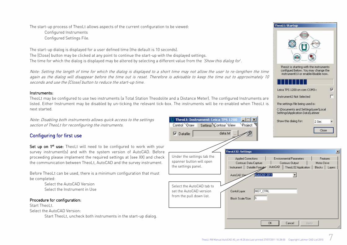
The start-up process of TheoLt allows aspects of the current configuration to be viewed:
Configured Instruments
Configured Settings File.
The start-up dialog is displayed for a user defined time (the default is 10 seconds).
The [Close] button may be clicked at any point to continue the start-up with the displayed settings.
The time for which the dialog is displayed may be altered by selecting a different value from the ‘Show this dialog for’. Note: Setting the length of time for which the dialog is displayed to a short time may not allow the user to re-lengthen the time again as the dialog will disappear before the time out is reset. Therefore is advisable to keep the time out to approximately 10 seconds and use the [Close] button to reduce the start-up time. Instruments:Instruments:Instruments:Instruments:
TheoLt may be configured to use two instruments (a Total Station Theodolite and a Distance Meter). The configured Instruments are listed. Either Instrument may be disabled by un-ticking the relevant tick-box. The instruments will be re-enabled when TheoLt is next started.
Note: Disabling both instruments allows quick access to the settings section of TheoLt for reconfiguring the instruments. Configuring for firsConfiguring for firsConfiguring for firsConfiguring for first uset uset uset use
Set up on 1Set up on 1Set up on 1Set up on 1stststst use: use: use: use: TheoLt will need to be configured to work with your survey instrument(s) and with the system version of AutoCAD. Before proceeding please implement the required settings at (see XX) and check
the communication between TheoLt, AutoCAD and the survey instrument. Before TheoLt can be used, there is a minimum configuration that must
be completed: Select the AutoCAD Version Select the Instrument in Use
Procedure for configurationProcedure for configurationProcedure for configurationProcedure for configuration:::: Start TheoLt.
Select the AutoCAD Version: Start TheoLt, uncheck both instruments in the start-up dialog.
Under the settings tab the
spanner button will open
the settings panel.
Select the AutoCAD tab to
set the AutoCAD version
from the pull down list.
8 TheoLt R8 Manual AutoCAD A5_en r8.20.docLast printed 27/07/2011 10:28:00 Copyright Latimer CAD Ltd 2010
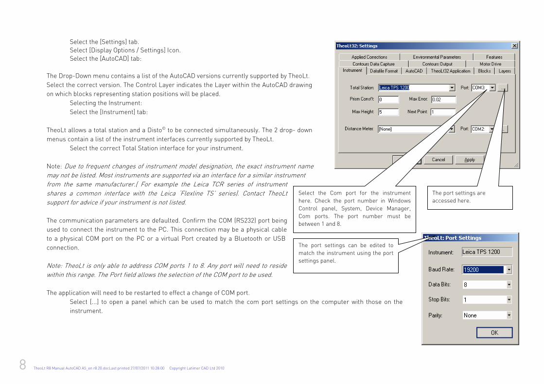
Select the [Settings] tab. Select [Display Options / Settings] Icon. Select the [AutoCAD] tab:
The Drop-Down menu contains a list of the AutoCAD versions currently supported by TheoLt.
Select the correct version. The Control Layer indicates the Layer within the AutoCAD drawing
on which blocks representing station positions will be placed.
Selecting the Instrument:
Select the [Instrument] tab:
TheoLt allows a total station and a Disto© to be connected simultaneously. The 2 drop- down
menus contain a list of the instrument interfaces currently supported by TheoLt.
Select the correct Total Station interface for your instrument.
Note: Due to frequent changes of instrument model designation, the exact instrument name
may not be listed. Most instruments are supported via an interface for a similar instrument
from the same manufacturer.( For example the Leica TCR series of instrument
shares a common interface with the Leica ‘Flexline TS’ series). Contact TheoLt
support for advice if your instrument is not listed.
The communication parameters are defaulted. Confirm the COM (RS232) port being
used to connect the instrument to the PC. This connection may be a physical cable
to a physical COM port on the PC or a virtual Port created by a Bluetooth or USB
connection.
Note: TheoLt is only able to address COM ports 1 to 8. Any port will need to reside
within this range. The Port field allows the selection of the COM port to be used.
The application will need to be restarted to effect a change of COM port.
Select [...] to open a panel which can be used to match the com port settings on the computer with those on the
instrument.
Select the Com port for the instrument
here. Check the port number in Windows
Control panel, System, Device Manager,
Com ports. The port number must be
between 1 and 8.
The port settings are
accessed here.
The port settings can be edited to
match the instrument using the port
settings panel.
TheoLt R8 Manual AutoCAD A5_en r8.20.docLast printed 27/07/2011 10:28:00 Copyright Latimer CAD Ltd 2010 9
Note: The instrument will have to be set up to send data via RS232, and have communication settings in agreement with TheoLt. TheoLt will need to be closed and restarted for instrument settings to effect changes to the comms settings.
Repeat for the Distance Meter selection and COM port. [Apply] the Settings. [OK] to
close the dialog box. [Close] TheoLt.
After re-starting, TheoLt will be ready to use.
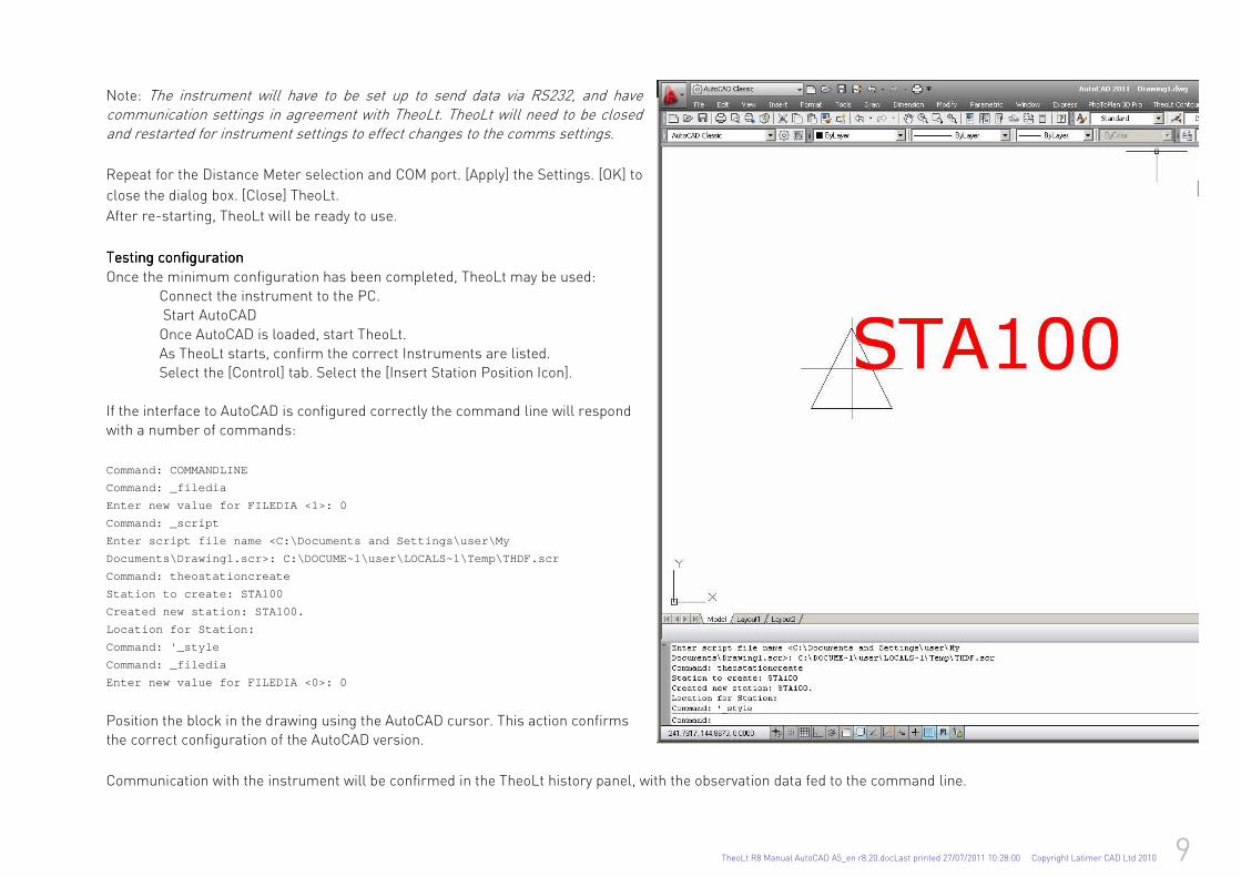
Testing configurationTesting configurationTesting configurationTesting configuration
Once the minimum configuration has been completed, TheoLt may be used: Connect the instrument to the PC. Start AutoCAD
Once AutoCAD is loaded, start TheoLt. As TheoLt starts, confirm the correct Instruments are listed. Select the [Control] tab. Select the [Insert Station Position Icon].
If the interface to AutoCAD is configured correctly the command line will respond with a number of commands:
Command: COMMANDLINE
Command: _filedia
Enter new value for FILEDIA <1>: 0
Command: _script
Enter script file name <C:\Documents and Settings\u ser\My
Documents\Drawing1.scr>: C:\DOCUME~1\user\LOCALS~1\ Temp\THDF.scr
Command: theostationcreate
Station to create: STA100
Created new station: STA100.
Location for Station:
Command: '_style
Command: _filedia
Enter new value for FILEDIA <0>: 0
Position the block in the drawing using the AutoCAD cursor. This action confirms the correct configuration of the AutoCAD version.
Communication with the instrument will be confirmed in the TheoLt history panel, with the observation data fed to the command line.

10 TheoLt R8 Manual AutoCAD A5_en r8.20.docLast printed 27/07/2011 10:28:00 Copyright Latimer CAD Ltd 2010
TroubleTroubleTroubleTrouble----shooting the systemshooting the systemshooting the systemshooting the system
IssueIssueIssueIssue Set to:Set to:Set to:Set to: Required status:Required status:Required status:Required status: See See See See
Dynamic input
Off Dynmode=0 AutoCAD Setvar
Dynamic UCS 0ff
Command line On ‘commandlinehide’ or Ctrl+9 keys
Multiple drawing session Off
‘Saveas’ looses file dialogue 1 Filedia=1 AutoCAD Setvar
Stn and Ref Block sizes ignore block scale Unitless, Block insert units in conflict with block size save set at
‘Unitless’ to DWT
Format, Units, Insertion Scale
Version mismatch Check TheoLt is set to your version of AutoCAD.
The ‘vertical’ AutoCAD products should use the interface for the core
version or ‘vanilla’ equivalent.
TheoLt settings
AutoCAD file search path Add theoltblocks to AutoCAD support path
AutoCAD ‘options’
Lost pull-down menu Menubar=1
Lost menu Menuload
DistToPlan Toolbar not displayed Toggle AutoCAD work spaces
TheoDisto fails to load Set support path settings to include TheoLt
Station block fails to inserts at 0,0 after
AutoCAD
Re-install theodisto.arx, restart system
Windows permissions
Set working path away from C:\ TheoLt settings
Windows security settings ‘Never Notify’ In ‘User Account Control’ Settings Control panel, User Accounts
TheoLt R8 Manual AutoCAD A5_en r8.20.docLast printed 27/07/2011 10:28:00 Copyright Latimer CAD Ltd 2010 11
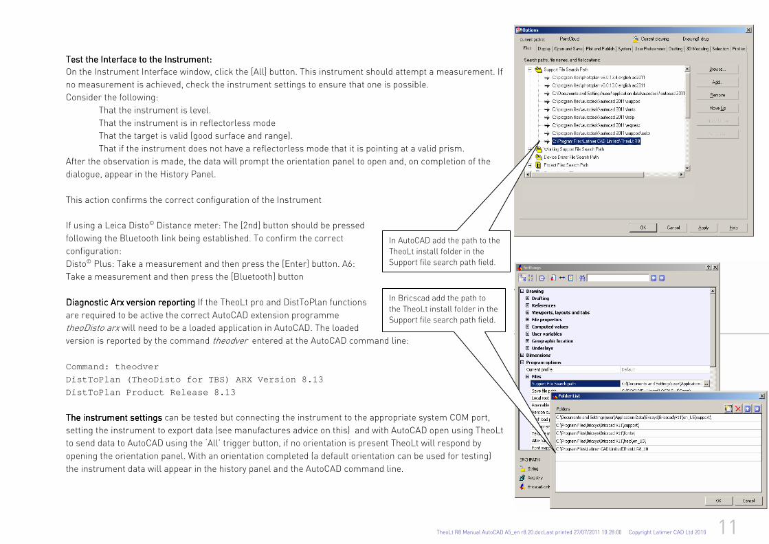
Test the Interface to the Instrument:Test the Interface to the Instrument:Test the Interface to the Instrument:Test the Interface to the Instrument:
On the Instrument Interface window, click the [All] button. This instrument should attempt a measurement. If
no measurement is achieved, check the instrument settings to ensure that one is possible.
Consider the following:
That the instrument is level.
That the instrument is in reflectorless mode
That the target is valid (good surface and range).
That if the instrument does not have a reflectorless mode that it is pointing at a valid prism.
After the observation is made, the data will prompt the orientation panel to open and, on completion of the
dialogue, appear in the History Panel.
This action confirms the correct configuration of the Instrument
If using a Leica Disto© Distance meter: The [2nd] button should be pressed
following the Bluetooth link being established. To confirm the correct
configuration:
Disto© Plus: Take a measurement and then press the [Enter] button. A6:
Take a measurement and then press the [Bluetooth] button
Diagnostic Diagnostic Diagnostic Diagnostic Arx version reportingArx version reportingArx version reportingArx version reporting If the TheoLt pro and DistToPlan functions
are required to be active the correct AutoCAD extension programme
theoDisto arx will need to be a loaded application in AutoCAD. The loaded
version is reported by the command theodver entered at the AutoCAD command line:
Command: theodver
DistToPlan (TheoDisto for TBS) ARX Version 8.13
DistToPlan Product Release 8.13
The instrument settingsThe instrument settingsThe instrument settingsThe instrument settings can be tested but connecting the instrument to the appropriate system COM port,
setting the instrument to export data (see manufactures advice on this) and with AutoCAD open using TheoLt
to send data to AutoCAD using the ‘All’ trigger button, if no orientation is present TheoLt will respond by
opening the orientation panel. With an orientation completed (a default orientation can be used for testing)
the instrument data will appear in the history panel and the AutoCAD command line.
In AutoCAD add the path to the
TheoLt install folder in the
Support file search path field.
In Bricscad add the path to
the TheoLt install folder in the
Support file search path field.

12 TheoLt R8 Manual AutoCAD A5_en r8.20.docLast printed 27/07/2011 10:28:00 Copyright Latimer CAD Ltd 2010
Suggested Suggested Suggested Suggested StartStartStartStart----up procedureup procedureup procedureup procedure
Surveying with TheoLt: basic procedure.Surveying with TheoLt: basic procedure.Surveying with TheoLt: basic procedure.Surveying with TheoLt: basic procedure.
Open AutoCAD and have the drawing you want to add to current.
1111
Prepare drawing
Prepare drawing
Prepare drawing
Prepare drawing
Check the drawing to make sure your position agrees with it: know ‘where you are’ in the drawing. Identify the stations you will be using both on the ground and in the drawing.
2222 Set up
Set up
Set up
Set up
instrument
instrument
instrument
instrument
Set up your instrument, centre it and level it. Measure and record the height of instrument from the ground (not the top of the peg)
to the instrument centre mark. Connect the tablet to the instrument and check the instrument level again. Make sure the tablet bag and instrument cases are closed after use to prevent
dirt getting in.
An orientation is required before points can be measured so open TheoLt.
3333 Orien
tate
Orien
tate
Orien
tate
Orien
tate
Send a point to TheoLt and the orientation panel will be prompted. Enter the occupied and reference positions, the instrument and target heights, take the shot, check it and accept
the orientation.
Check TheoLt is in the draw tab with the transparent tool set,
select an AutoCAD layer, select the line tool and off you go!
Saving the drawing saves the work. 4444 S
urvey
Survey
Survey
Survey
Use the control tab and follow the on-screen prompts following
measurement to set out more stations as required.
TheoLt R8 Manual AutoCAD A5_en r8.20.docLast printed 27/07/2011 10:28:00 Copyright Latimer CAD Ltd 2010 13
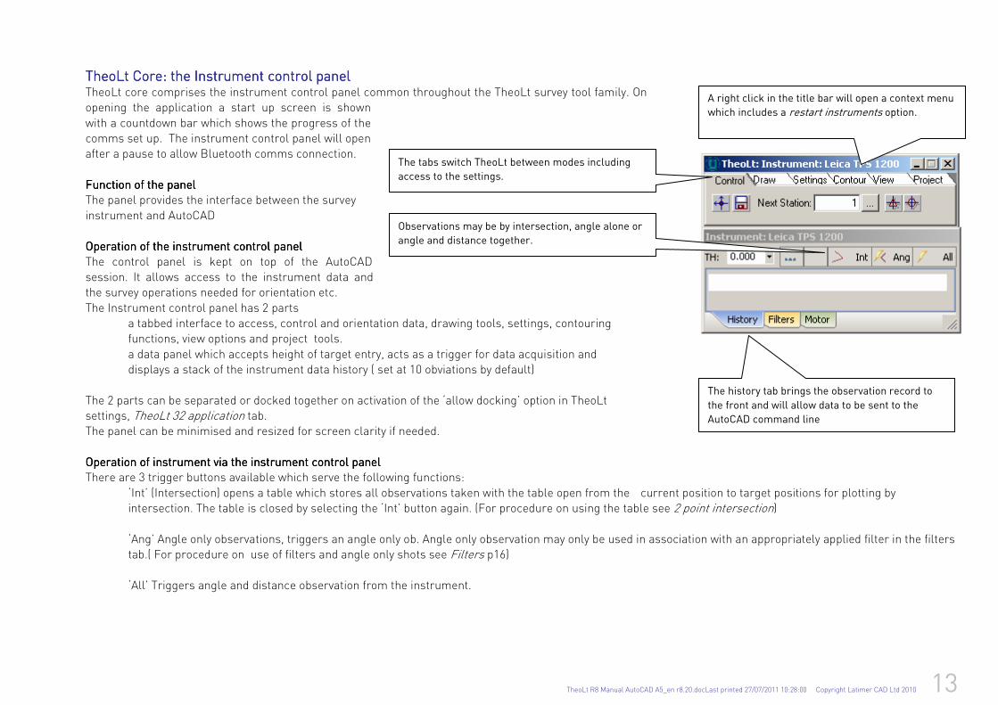
The history tab brings the observation record to
the front and will allow data to be sent to the
AutoCAD command line
The tabs switch TheoLt between modes including
access to the settings.
Observations may be by intersection, angle alone or
angle and distance together.
A right click in the title bar will open a context menu
which includes a restart instruments option.
TheoLt CoreTheoLt CoreTheoLt CoreTheoLt Core:::: the Instrument control panel the Instrument control panel the Instrument control panel the Instrument control panel TheoLt core comprises the instrument control panel common throughout the TheoLt survey tool family. On opening the application a start up screen is shown
with a countdown bar which shows the progress of the comms set up. The instrument control panel will open after a pause to allow Bluetooth comms connection.
Function of the panelFunction of the panelFunction of the panelFunction of the panel The panel provides the interface between the survey
instrument and AutoCAD Operation of the Operation of the Operation of the Operation of the instrument control instrument control instrument control instrument control panelpanelpanelpanel
The control panel is kept on top of the AutoCAD session. It allows access to the instrument data and the survey operations needed for orientation etc.
The Instrument control panel has 2 parts a tabbed interface to access, control and orientation data, drawing tools, settings, contouring functions, view options and project tools.
a data panel which accepts height of target entry, acts as a trigger for data acquisition and displays a stack of the instrument data history ( set at 10 obviations by default)
The 2 parts can be separated or docked together on activation of the ‘allow docking’ option in TheoLt settings, TheoLt 32 application tab. The panel can be minimised and resized for screen clarity if needed.
Operation of instrument via the instrument control panelOperation of instrument via the instrument control panelOperation of instrument via the instrument control panelOperation of instrument via the instrument control panel There are 3 trigger buttons available which serve the following functions:
‘Int’ (Intersection) opens a table which stores all observations taken with the table open from the current position to target positions for plotting by intersection. The table is closed by selecting the ‘Int’ button again. (For procedure on using the table see 2 point intersection)
‘Ang’ Angle only observations, triggers an angle only ob. Angle only observation may only be used in association with an appropriately applied filter in the filters tab.( For procedure on use of filters and angle only shots see Filters p16)
‘All’ Triggers angle and distance observation from the instrument.
14 TheoLt R8 Manual AutoCAD A5_en r8.20.docLast printed 27/07/2011 10:28:00 Copyright Latimer CAD Ltd 2010
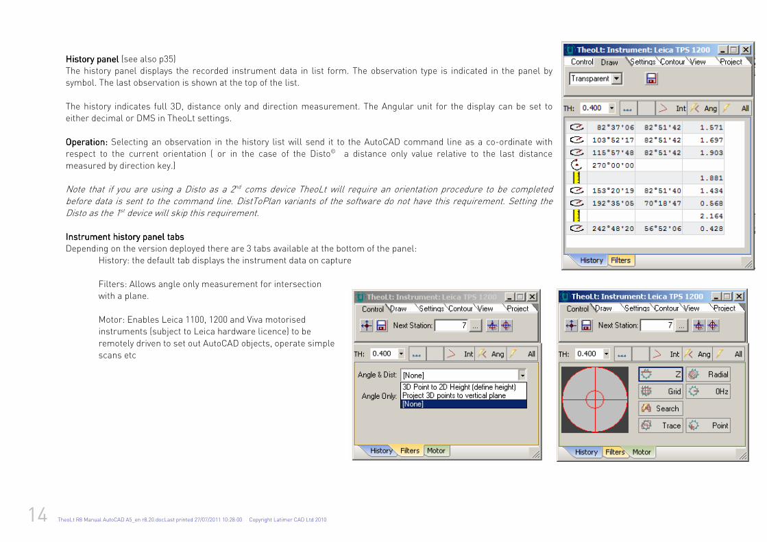
History panelHistory panelHistory panelHistory panel (see also p35) The history panel displays the recorded instrument data in list form. The observation type is indicated in the panel by symbol. The last observation is shown at the top of the list.
The history indicates full 3D, distance only and direction measurement. The Angular unit for the display can be set to either decimal or DMS in TheoLt settings.
Operation: Operation: Operation: Operation: Selecting an observation in the history list will send it to the AutoCAD command line as a co-ordinate with respect to the current orientation ( or in the case of the Disto© a distance only value relative to the last distance
measured by direction key.) Note that if you are using a Disto as a 2nd coms device TheoLt will require an orientation procedure to be completed before data is sent to the command line. DistToPlan variants of the software do not have this requirement. Setting the Disto as the 1st device will skip this requirement.
Instrument Instrument Instrument Instrument histohistohistohistoryryryry panel panel panel panel tabstabstabstabs Depending on the version deployed there are 3 tabs available at the bottom of the panel:
History: the default tab displays the instrument data on capture
Filters: Allows angle only measurement for intersection
with a plane.
Motor: Enables Leica 1100, 1200 and Viva motorised instruments (subject to Leica hardware licence) to be
remotely driven to set out AutoCAD objects, operate simple scans etc
TheoLt R8 Manual AutoCAD A5_en r8.20.docLast printed 27/07/2011 10:28:00 Copyright Latimer CAD Ltd 2010 15
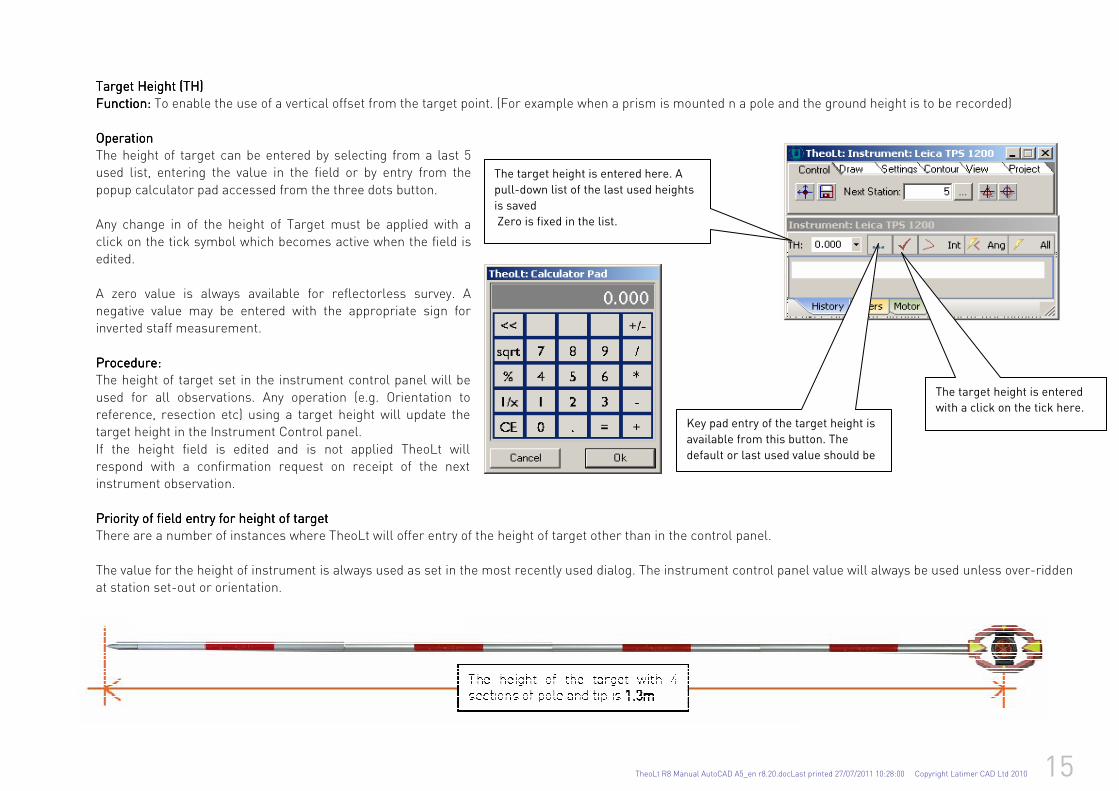
TTTTargetargetargetarget Height Height Height Height (TH)(TH)(TH)(TH) Function:Function:Function:Function: To enable the use of a vertical offset from the target point. (For example when a prism is mounted n a pole and the ground height is to be recorded)
OperationOperationOperationOperation The height of target can be entered by selecting from a last 5 used list, entering the value in the field or by entry from the
popup calculator pad accessed from the three dots button. Any change in of the height of Target must be applied with a
click on the tick symbol which becomes active when the field is edited.
A zero value is always available for reflectorless survey. A negative value may be entered with the appropriate sign for inverted staff measurement.
Procedure:Procedure:Procedure:Procedure: The height of target set in the instrument control panel will be
used for all observations. Any operation (e.g. Orientation to reference, resection etc) using a target height will update the target height in the Instrument Control panel.
If the height field is edited and is not applied TheoLt will respond with a confirmation request on receipt of the next instrument observation.
Priority of field entry for height of Priority of field entry for height of Priority of field entry for height of Priority of field entry for height of tatatatarrrrgetgetgetget There are a number of instances where TheoLt will offer entry of the height of target other than in the control panel.
The value for the height of instrument is always used as set in the most recently used dialog. The instrument control panel value will always be used unless over-ridden at station set-out or orientation.
The target height is entered
with a click on the tick here.
Key pad entry of the target height is
available from this button. The
default or last used value should be
cleared before use.
The target height is entered here. A
pull-down list of the last used heights
is saved
Zero is fixed in the list.
16 TheoLt R8 Manual AutoCAD A5_en r8.20.docLast printed 27/07/2011 10:28:00 Copyright Latimer CAD Ltd 2010
FiltersFiltersFiltersFilters
Function: Function: Function: Function: to allow use of angle only observations for plotting by intersection with a plane or by plotting to a clipped height for (2D plots)
The instrument filters allow specific observation types to be modified. The 2 observation types are:
Angle and distance
Angle only
Angle & distance filter: projecting 3D point to 2d heightAngle & distance filter: projecting 3D point to 2d heightAngle & distance filter: projecting 3D point to 2d heightAngle & distance filter: projecting 3D point to 2d height::::
This allows all 3D observations to be converted to 2D as they are made (for example during the measurement of a building plan)
Angle & distance filter: Projecting 3D point to vertical planeAngle & distance filter: Projecting 3D point to vertical planeAngle & distance filter: Projecting 3D point to vertical planeAngle & distance filter: Projecting 3D point to vertical plane::::
This allows all 3D observations to be projected onto a vertical plane defined by 2 points. All observations are projected perpendicularly to the plane (as opposed to Angle
only observations which are plotted at the intersection of the observation and the plane.)
Project to XYProject to XYProject to XYProject to XY, , , , if this is selected the plane may be projected to the X-Y world co-ordinate plane in AutoCAD. If de-selected the points are plotted at the true 3D position
on the plane.
Angle only Angle only Angle only Angle only filterfilterfilterfilter: project Intersection with Vertical Plane: project Intersection with Vertical Plane: project Intersection with Vertical Plane: project Intersection with Vertical Plane::::
This allows all Angle Only observations to be intersected with a vertical plane defined by 2 points.
The [Project to X-Y] if selected the plane may be projected to the X-Y world coordinate plane in AutoCAD. If de-selected, the points are plotted at the true 3D position on
the plane.
Angle only filterAngle only filterAngle only filterAngle only filter---- remote elevation remote elevation remote elevation remote elevation::::
For each observation the vertical angle is used to calculate the height (z value) over the last full 3D (Angle and distance) point observed. i.e. when an Angle Only
observation is received, the X and Y values of the last Angle and Distance observation is taken in conjunction with the vertical angle of the new observation to plot a
point directly over the 1st one.
Angle only filter: Horizontal offsetAngle only filter: Horizontal offsetAngle only filter: Horizontal offsetAngle only filter: Horizontal offset
For each Angle Only observation the Horizontal angle is combined with the Distance and Vertical angle Measurements from the last full 3D (Angle and Distance) point
observed.
Angle only filter: H and V AngAngle only filter: H and V AngAngle only filter: H and V AngAngle only filter: H and V Angle offsetle offsetle offsetle offset
For each Angle Only observation the Horizontal and vertical angles are combined with the Distance Measurement from the last full 3D (Angle and Distance) point
observed.
TheoLt R8 Manual AutoCAD A5_en r8.20.docLast printed 27/07/2011 10:28:00 Copyright Latimer CAD Ltd 2010 17
ProjectProjectProjectProjectssss in TheoLt in TheoLt in TheoLt in TheoLt Function of the Function of the Function of the Function of the Project tabProject tabProject tabProject tab
To organise the data for adjustment, separation of pre- and post- adjust data, station numbering, room handling and QA verification TheoLt will create and store data
files in a specific folder. The advantage of working with TheoLt Project folder is that entire data sets can be moved easily to and from field systems for data backup and
integration. On first use a TheoLt project can be set or the ‘default’ project accepted.
New site = new project
New set up =new orientation
By default the arx enabled versions of TheoLt will prompt AutoCAD to save the current drawing in the project folder.
Work can be divided between projects and brought together using the project folder.
Projects are folders containing the survey data, orientation records, station lists, verification reports and calculation data which are required for operations such as QA,
network calculation and grouped data processing ( such as room handling in building survey or post processing of radial observation by network adjustment) )created
as subfolders under a project path folder.
By default on start up TheoLt opens in the Project tab (this setting can be modified if desired: see TheoLt settings) a project can be created or selected to organise the
survey data files.
Default settingsDefault settingsDefault settingsDefault settings
TheoLt will open in the Project tab by default as a procedural aid. The last used project will be offered as the current project unless action is taken, (The ‘start in project
tab’ behaviour can be changed in TheoLt settings)On installation a default project and project path are set; these locations can be modified to user requirement in
settings (see Settings) For simplicity of data transfer the arx enabled versions of TheoLt will prompt AutoCAD to save the current drawing in the project folder this
function can be disabled at the settings option in TheoLt Building Survey in AutoCAD
Each project contains:
Project name
Project description
Project originator/author
Date created
Starting position number
Last used Station position number
A list of the station positions used
A list of the orientations used in the project
The position verification data for the project
Optional: User formatted text data files(s)
Optional: Unformatted raw instrument data file(s)
Pro versions: Network adjustment reports, pre- and post- adjust station lists
18 TheoLt R8 Manual AutoCAD A5_en r8.20.docLast printed 27/07/2011 10:28:00 Copyright Latimer CAD Ltd 2010
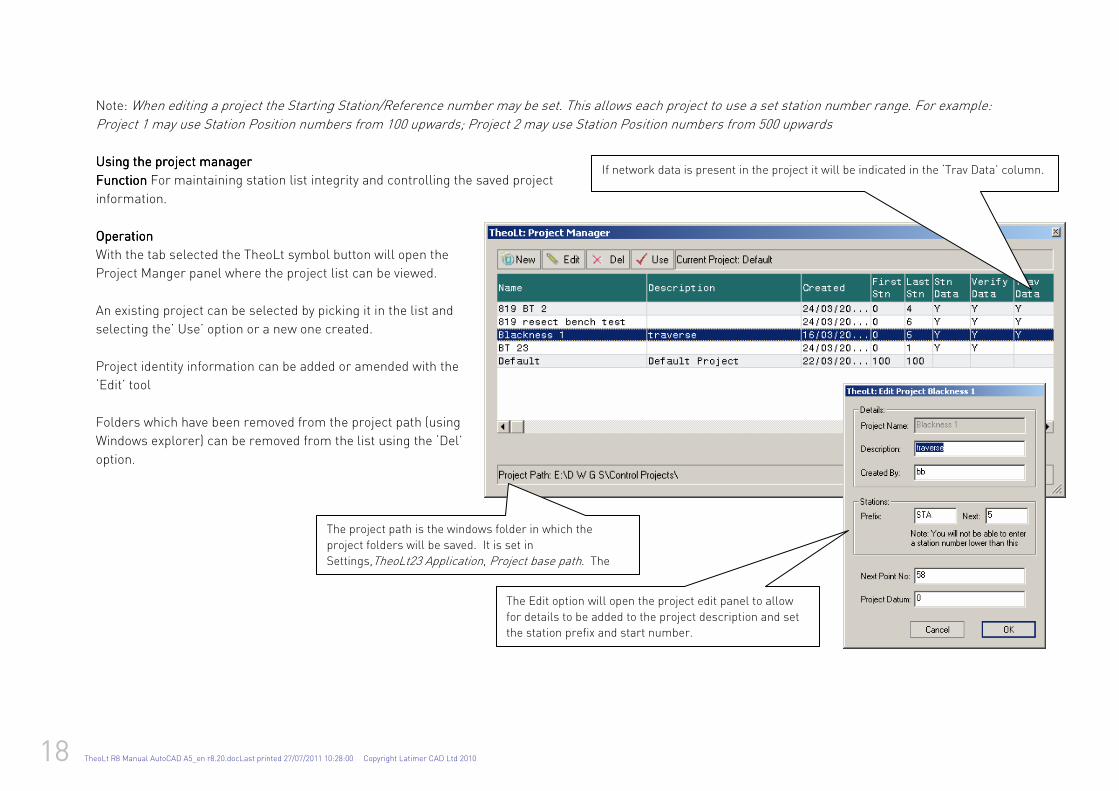
The project path is the windows folder in which the
project folders will be saved. It is set in
Settings,TheoLt23 Application, Project base path. The default is ‘My TheoLt Projects’ under the current user
The Edit option will open the project edit panel to allow
for details to be added to the project description and set
the station prefix and start number.
If network data is present in the project it will be indicated in the ‘Trav Data’ column.
Note: When editing a project the Starting Station/Reference number may be set. This allows each project to use a set station number range. For example:
Project 1 may use Station Position numbers from 100 upwards; Project 2 may use Station Position numbers from 500 upwards
Using the project managerUsing the project managerUsing the project managerUsing the project manager
FunctionFunctionFunctionFunction For maintaining station list integrity and controlling the saved project
information.
OperationOperationOperationOperation
With the tab selected the TheoLt symbol button will open the
Project Manger panel where the project list can be viewed.
An existing project can be selected by picking it in the list and
selecting the’ Use’ option or a new one created.
Project identity information can be added or amended with the
‘Edit’ tool
Folders which have been removed from the project path (using
Windows explorer) can be removed from the list using the ‘Del’
option.
TheoLt R8 Manual AutoCAD A5_en r8.20.docLast printed 27/07/2011 10:28:00 Copyright Latimer CAD Ltd 2010 19
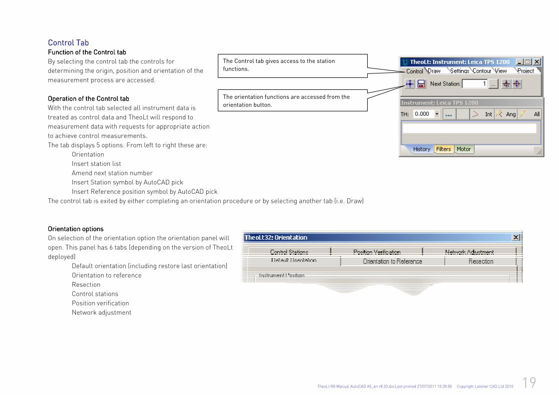
Control TabControl TabControl TabControl Tab Function of the Function of the Function of the Function of the Control tabControl tabControl tabControl tab
By selecting the control tab the controls for
determining the origin, position and orientation of the
measurement process are accessed.
Operation of the Operation of the Operation of the Operation of the Control tabControl tabControl tabControl tab
With the control tab selected all instrument data is
treated as control data and TheoLt will respond to
measurement data with requests for appropriate action
to achieve control measurements.
The tab displays 5 options. From left to right these are:
Orientation
Insert station list
Amend next station number
Insert Station symbol by AutoCAD pick
Insert Reference position symbol by AutoCAD pick
The control tab is exited by either completing an orientation procedure or by selecting another tab (i.e. Draw)
Orientation optionsOrientation optionsOrientation optionsOrientation options
On selection of the orientation option the orientation panel will
open. This panel has 6 tabs (depending on the version of TheoLt
deployed)
Default orientation (including restore last orientation)
Orientation to reference
Resection
Control stations
Position verification
Network adjustment
The orientation functions are accessed from the
orientation button.
The Control tab gives access to the station
functions.
20 TheoLt R8 Manual AutoCAD A5_en r8.20.docLast printed 27/07/2011 10:28:00 Copyright Latimer CAD Ltd 2010
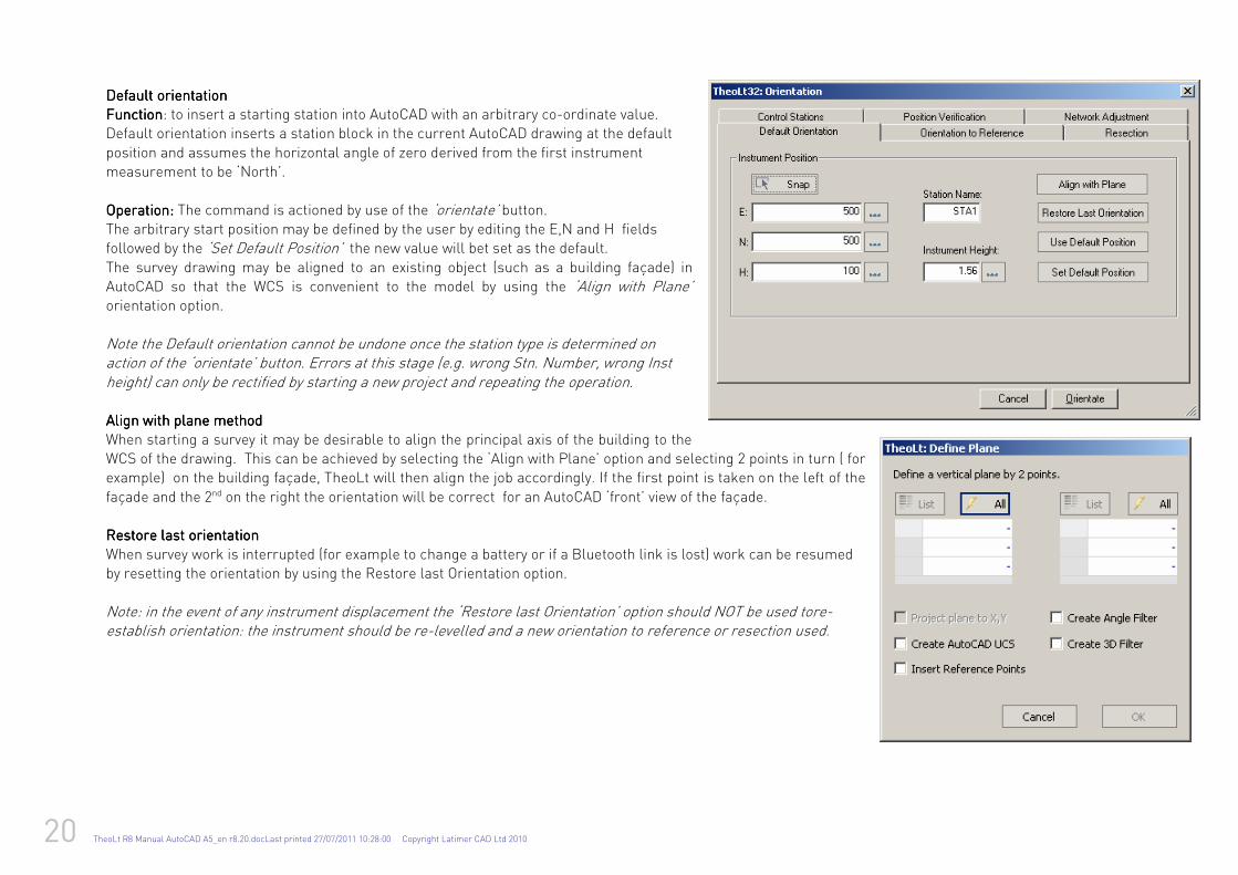
Default orientationDefault orientationDefault orientationDefault orientation FunctionFunctionFunctionFunction: to insert a starting station into AutoCAD with an arbitrary co-ordinate value. Default orientation inserts a station block in the current AutoCAD drawing at the default
position and assumes the horizontal angle of zero derived from the first instrument measurement to be ‘North’.
Operation:Operation:Operation:Operation: The command is actioned by use of the ‘orientate’ button. The arbitrary start position may be defined by the user by editing the E,N and H fields followed by the ‘Set Default Position’ the new value will bet set as the default. The survey drawing may be aligned to an existing object (such as a building façade) in AutoCAD so that the WCS is convenient to the model by using the ‘Align with Plane’ orientation option.
Note the Default orientation cannot be undone once the station type is determined on action of the ‘orientate’ button. Errors at this stage (e.g. wrong Stn. Number, wrong Inst height) can only be rectified by starting a new project and repeating the operation. Align with plane methodAlign with plane methodAlign with plane methodAlign with plane method
When starting a survey it may be desirable to align the principal axis of the building to the WCS of the drawing. This can be achieved by selecting the ‘Align with Plane’ option and selecting 2 points in turn ( for example) on the building façade, TheoLt will then align the job accordingly. If the first point is taken on the left of the
façade and the 2nd on the right the orientation will be correct for an AutoCAD ‘front’ view of the façade. Restore last orientationRestore last orientationRestore last orientationRestore last orientation
When survey work is interrupted (for example to change a battery or if a Bluetooth link is lost) work can be resumed by resetting the orientation by using the Restore last Orientation option. Note: in the event of any instrument displacement the ‘Restore last Orientation’ option should NOT be used tore-establish orientation: the instrument should be re-levelled and a new orientation to reference or resection used.
TheoLt R8 Manual AutoCAD A5_en r8.20.docLast printed 27/07/2011 10:28:00 Copyright Latimer CAD Ltd 2010 21
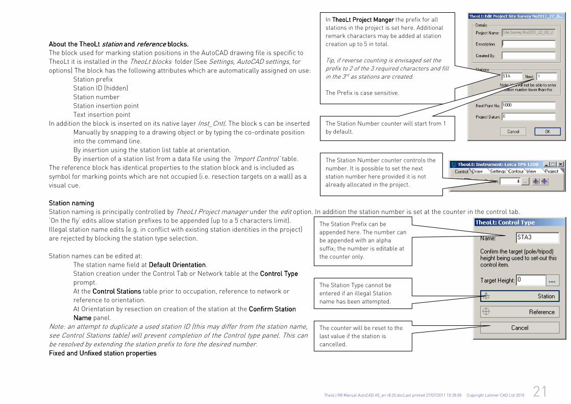
About the TheoLt About the TheoLt About the TheoLt About the TheoLt stationstationstationstation and and and and referencereferencereferencereference blocks. blocks. blocks. blocks. The block used for marking station positions in the AutoCAD drawing file is specific to TheoLt it is installed in the TheoLt blocks folder (See Settings, AutoCAD settings, for options) The block has the following attributes which are automatically assigned on use:
Station prefix Station ID (hidden)
Station number Station insertion point Text insertion point
In addition the block is inserted on its native layer Inst_Cntl. The block s can be inserted Manually by snapping to a drawing object or by typing the co-ordinate position into the command line.
By insertion using the station list table at orientation. By insertion of a station list from a data file using the ‘Import Control’ table.
The reference block has identical properties to the station block and is included as
symbol for marking points which are not occupied (i.e. resection targets on a wall) as a visual cue.
Station naming Station naming Station naming Station naming Station naming is principally controlled by TheoLt Project manager under the edit option. In addition the station number is set at the counter in the control tab. ‘On the fly’ edits allow station prefixes to be appended (up to a 5 characters limit).
Illegal station name edits (e.g. in conflict with existing station identities in the project) are rejected by blocking the station type selection.
Station names can be edited at: The station name field at Default Default Default Default OrientationOrientationOrientationOrientation. Station creation under the Control Tab or Network table at the Control TypeControl TypeControl TypeControl Type
prompt. At the Control StationsControl StationsControl StationsControl Stations table prior to occupation, reference to network or reference to orientation.
At Orientation by resection on creation of the station at the Confirm Station Confirm Station Confirm Station Confirm Station NameNameNameName panel. Note: an attempt to duplicate a used station ID (this may differ from the station name, see Control Stations table) will prevent completion of the Control type panel. This can be resolved by extending the station prefix to fore the desired number. Fixed and Unfixed station propertiesFixed and Unfixed station propertiesFixed and Unfixed station propertiesFixed and Unfixed station properties
The Station Prefix can be
appended here. The number can
be appended with an alpha
suffix; the number is editable at
the counter only.
The Station Type cannot be
entered if an illegal Station
name has been attempted.
The counter will be reset to the
last value if the station is
cancelled.
The Station Number counter controls the
number. It is possible to set the next
station number here provided it is not
already allocated in the project.
In TheoLt Project MangerTheoLt Project MangerTheoLt Project MangerTheoLt Project Manger the prefix for all
stations in the project is set here. Additional
remark characters may be added at station
creation up to 5 in total.
Tip, if reverse counting is envisaged set the prefix to 2 of the 3 required characters and fill in the 3rd as stations are created. The Prefix is case sensitive.
The Station Number counter will start from 1
by default.
22 TheoLt R8 Manual AutoCAD A5_en r8.20.docLast printed 27/07/2011 10:28:00 Copyright Latimer CAD Ltd 2010
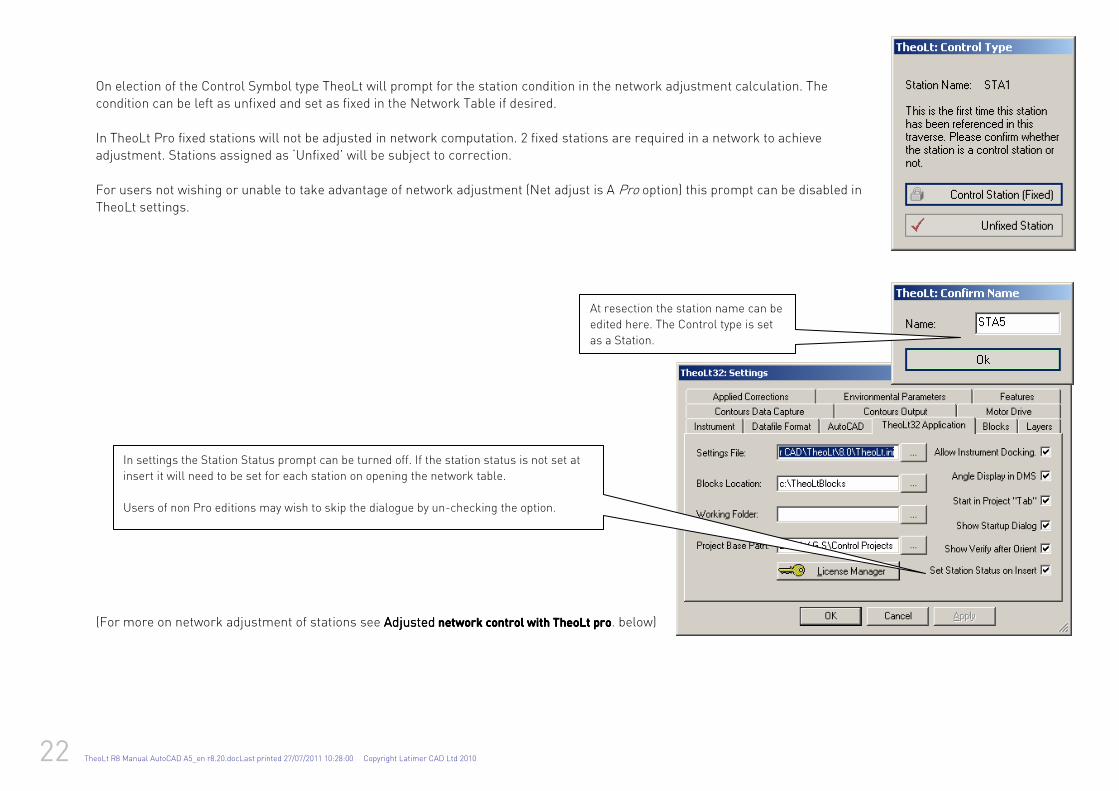
On election of the Control Symbol type TheoLt will prompt for the station condition in the network adjustment calculation. The condition can be left as unfixed and set as fixed in the Network Table if desired.
In TheoLt Pro fixed stations will not be adjusted in network computation. 2 fixed stations are required in a network to achieve adjustment. Stations assigned as ‘Unfixed’ will be subject to correction.
For users not wishing or unable to take advantage of network adjustment (Net adjust is A Pro option) this prompt can be disabled in TheoLt settings.
(For more on network adjustment of stations see AdjustedAdjustedAdjustedAdjusted network control with TheoLt pronetwork control with TheoLt pronetwork control with TheoLt pronetwork control with TheoLt pro. below)
In settings the Station Status prompt can be turned off. If the station status is not set at
insert it will need to be set for each station on opening the network table.
Users of non Pro editions may wish to skip the dialogue by un-checking the option.
At resection the station name can be
edited here. The Control type is set
as a Station.
TheoLt R8 Manual AutoCAD A5_en r8.20.docLast printed 27/07/2011 10:28:00 Copyright Latimer CAD Ltd 2010 23
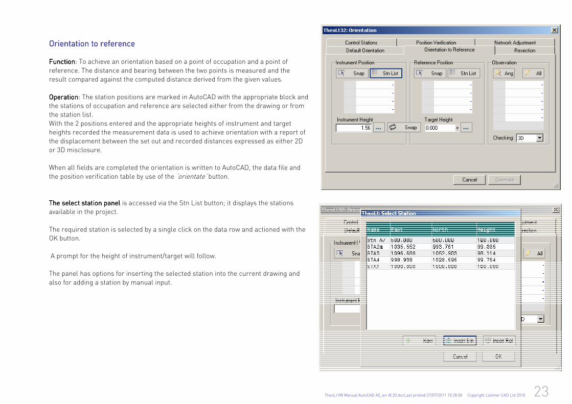
Orientation to referenceOrientation to referenceOrientation to referenceOrientation to reference FunctionFunctionFunctionFunction: To achieve an orientation based on a point of occupation and a point of
reference. The distance and bearing between the two points is measured and the result compared against the computed distance derived from the given values.
OperationOperationOperationOperation: The station positions are marked in AutoCAD with the appropriate block and the stations of occupation and reference are selected either from the drawing or from the station list.
With the 2 positions entered and the appropriate heights of instrument and target heights recorded the measurement data is used to achieve orientation with a report of the displacement between the set out and recorded distances expressed as either 2D
or 3D misclosure. When all fields are completed the orientation is written to AutoCAD, the data file and
the position verification table by use of the ‘orientate’ button.
The select station panel The select station panel The select station panel The select station panel is accessed via the Stn List button; it displays the stations available in the project.
The required station is selected by a single click on the data row and actioned with the OK button.
A prompt for the height of instrument/target will follow. The panel has options for inserting the selected station into the current drawing and
also for adding a station by manual input.
24 TheoLt R8 Manual AutoCAD A5_en r8.20.docLast printed 27/07/2011 10:28:00 Copyright Latimer CAD Ltd 2010
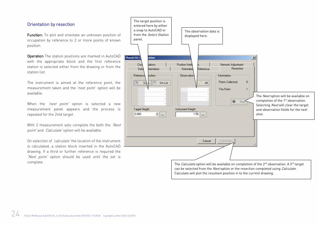
Orientation by rOrientation by rOrientation by rOrientation by resectionesectionesectionesection
Function:Function:Function:Function: To plot and orientate an unknown position of
occupation by reference to 2 or more points of known
position.
OperationOperationOperationOperation The station positions are marked in AutoCAD
with the appropriate block and the first reference
station is selected either from the drawing or from the
station list.
The instrument is aimed at the reference point, the
measurement taken and the ‘next point’ option will be
available.
When the ‘next point’ option is selected a new
measurement panel appears and the process is
repeated for the 2ntd target.
With 2 measurement sets complete the both the ‘Next
point’ and ‘Calculate’ option will be available.
On selection of ‘calculate’ the location of the instrument
is calculated, a station block inserted in the AutoCAD
drawing. If a third or further reference is required the
‘Next point’ option should be used until the set is
complete.
The target position is
entered here by either
a snap to AutoCAD or
from the Select Station panel.
The observation data is
displayed here.
The Next option will be available on completion of the 1st observation.
Selecting Next will clear the target and observation fields for the next
shot.
The Calculate option will be available on completion of the 2nd observation. A 3rd target
can be selected from the Next option or the resection completed using Calculate. Calculate will plot the resultant position in to the current drawing.
TheoLt R8 Manual AutoCAD A5_en r8.20.docLast printed 27/07/2011 10:28:00 Copyright Latimer CAD Ltd 2010 25
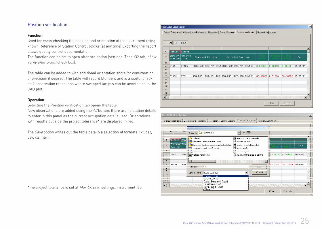
Position verificationPosition verificationPosition verificationPosition verification
Function:Function:Function:Function:
Used for cross checking the position and orientation of the instrument using
known Reference or Station Control blocks (at any time) Exporting the report
allows quality control documentation. The function can be set to open after ordination (settings, Theolt32 tab, show
verify after orient check box).
The table can be added to with additional orientation shots for confirmation
of precision if desired. The table will record blunders and is a useful check
on 2 observation resections where swapped targets can be undetected in the
CAD plot.
OperationOperationOperationOperation:
Selecting the Position verification tab opens the table.
New observations are added using the All button. there are no station details
to enter in this panel as the current occupation data is used. Orientations
with results out side the project tolerance* are displayed in red.
The Save option writes out the table data in a selection of formats: txt, dat,
csv, xls, html
*the project tolerance is set at Max Error in settings, instrument tab
26 TheoLt R8 Manual AutoCAD A5_en r8.20.docLast printed 27/07/2011 10:28:00 Copyright Latimer CAD Ltd 2010
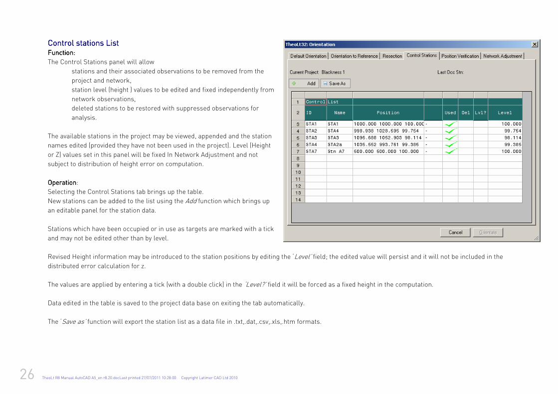
Control stationsControl stationsControl stationsControl stations List List List List Function:Function:Function:Function:
The Control Stations panel will allow
stations and their associated observations to be removed from the
project and network,
station level (height ) values to be edited and fixed independently from
network observations,
deleted stations to be restored with suppressed observations for
analysis.
The available stations in the project may be viewed, appended and the station
names edited (provided they have not been used in the project). Level (Height
or Z) values set in this panel will be fixed In Network Adjustment and not
subject to distribution of height error on computation.
OperationOperationOperationOperation:
Selecting the Control Stations tab brings up the table.
New stations can be added to the list using the Add function which brings up
an editable panel for the station data.
Stations which have been occupied or in use as targets are marked with a tick
and may not be edited other than by level.
Revised Height information may be introduced to the station positions by editing the ‘Level’ field; the edited value will persist and it will not be included in the
distributed error calculation for z.
The values are applied by entering a tick (with a double click) in the ‘Level?’ field it will be forced as a fixed height in the computation.
Data edited in the table is saved to the project data base on exiting the tab automatically.
The ‘Save as’ function will export the station list as a data file in .txt,.dat,.csv,.xls,.htm formats.
TheoLt R8 Manual AutoCAD A5_en r8.20.docLast printed 27/07/2011 10:28:00 Copyright Latimer CAD Ltd 2010 27
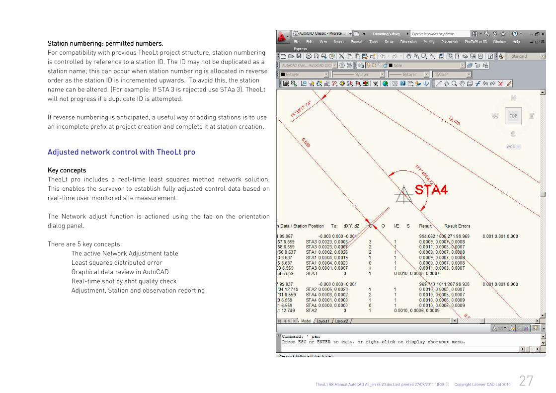
Station numbering: permitted numbers.Station numbering: permitted numbers.Station numbering: permitted numbers.Station numbering: permitted numbers.
For compatibility with previous TheoLt project structure, station numbering
is controlled by reference to a station ID. The ID may not be duplicated as a
station name; this can occur when station numbering is allocated in reverse
order as the station ID is incremented upwards. To avoid this, the station
name can be altered. (For example: If STA 3 is rejected use STAa 3). TheoLt
will not progress if a duplicate ID is attempted.
If reverse numbering is anticipated, a useful way of adding stations is to use
an incomplete prefix at project creation and complete it at station creation.
Adjusted network control with TheoLt pro
Key conceptsKey conceptsKey conceptsKey concepts
TheoLt pro includes a real-time least squares method network solution.
This enables the surveyor to establish fully adjusted control data based on
real-time user monitored site measurement.
The Network adjust function is actioned using the tab on the orientation
dialog panel.
There are 5 key concepts:
The active Network Adjustment table
Least squares distributed error
Graphical data review in AutoCAD
Real-time shot by shot quality check
Adjustment, Station and observation reporting
28 TheoLt R8 Manual AutoCAD A5_en r8.20.docLast printed 27/07/2011 10:28:00 Copyright Latimer CAD Ltd 2010
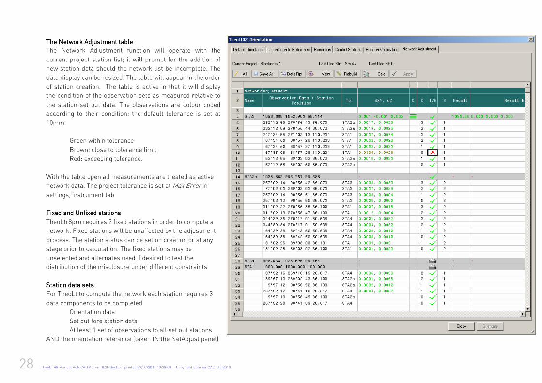
The Network Adjustment tableThe Network Adjustment tableThe Network Adjustment tableThe Network Adjustment table
The Network Adjustment function will operate with the
current project station list; it will prompt for the addition of
new station data should the network list be incomplete. The
data display can be resized. The table will appear in the order
of station creation. The table is active in that it will display
the condition of the observation sets as measured relative to
the station set out data. The observations are colour coded
according to their condition: the default tolerance is set at
10mm.
Green within tolerance
Brown: close to tolerance limit
Red: exceeding tolerance.
With the table open all measurements are treated as active
network data. The project tolerance is set at Max Error in
settings, instrument tab.
Fixed and Unfixed stationsFixed and Unfixed stationsFixed and Unfixed stationsFixed and Unfixed stations
TheoLtr8pro requires 2 fixed stations in order to compute a
network. Fixed stations will be unaffected by the adjustment
process. The station status can be set on creation or at any
stage prior to calculation. The fixed stations may be
unselected and alternates used if desired to test the
distribution of the misclosure under different constraints.
Station data setsStation data setsStation data setsStation data sets
For TheoLt to compute the network each station requires 3
data components to be completed.
Orientation data
Set out fore station data
At least 1 set of observations to all set out stations
AND the orientation reference (taken IN the NetAdjust panel)
TheoLt R8 Manual AutoCAD A5_en r8.20.docLast printed 27/07/2011 10:28:00 Copyright Latimer CAD Ltd 2010 29
Measurements may be taken on both faces of the instrument and may be ‘one way’ reflectorless observations to reference targets (e.g. to be used as reference stations for future resections).
Note: Leica 1200 series instruments with a single face control panel reverse the recorded horizontal angle reading on face 2 when data is sent from the instrument: this is effect is avoided if data is called from TheoLt using the All button in the table.
DaDaDaData quality checkta quality checkta quality checkta quality check Calc can be used to check data conformity at any time. The Calc function will analyse the data and present an up date of the adjusted station positions at any time during data capture as a check on the quality of work and as a proof of data conformity. View will plot the current network observation data to the current DWG. On use
of view the instrument observation data is plotted, as a ray, in a discrete layer, updated on each use of the view command. Data safety and reportingData safety and reportingData safety and reportingData safety and reporting
Project data backup, and export for sub-networks are managed by the options available on completion of calculation actioned by the ‘Apply’ option. Backup and reporting are available in a variety of formats at anytime during data capture. The Apply options allow the network data to be stored as raw dataraw dataraw dataraw data (using the TheoLt data file see settings, datafile ), pre and post adjusted station listspre and post adjusted station listspre and post adjusted station listspre and post adjusted station lists and DWG. DWG. DWG. DWG. New projects with the adjusted data as fixed stations can be created for the use of sub-
networks for minor control of detail survey if required. Primary (Network) orientation Primary (Network) orientation Primary (Network) orientation Primary (Network) orientation (including orientation to GPS derived data)
The 2 required fixed stations will determine the orientation of the network. If 2 stations have been established from GPS only one should be fixed. The second may be used for orientation but should NOT be assigned a fixed status nor included in the network loop as if more than one GPS derived position is included a distribution of a disproportionate error across Total Station measurement will occur.
Orientation procedure at Station OccupationOrientation procedure at Station OccupationOrientation procedure at Station OccupationOrientation procedure at Station Occupation Orient to reference or resection used. Once the orientation is complete fore-stations should be set out with the appropriate target heights assigned.
Station observation setsStation observation setsStation observation setsStation observation sets Once orientation and setting out stations is complete a complete observation set is required. A single round including the backsight and all set out stns will suffice but
multiple rounds will improve precision. TheoLt NetAdjust will automatically prompt for station ID and target height. Checking progressChecking progressChecking progressChecking progress
Calc and view will update the table and DWG respectively. The calc will display the current state of the network distribution of error in RED. An indication of a complete
station data set comprises an ‘O’ column ‘O’ column ‘O’ column ‘O’ column value indicating observation status and a concomitant ‘S’ column‘S’ column‘S’ column‘S’ column value indicating station set status to the required targets.
30 TheoLt R8 Manual AutoCAD A5_en r8.20.docLast printed 27/07/2011 10:28:00 Copyright Latimer CAD Ltd 2010
Dealing with corrupted station locations and Dealing with corrupted station locations and Dealing with corrupted station locations and Dealing with corrupted station locations and orientationorientationorientationorientation (other than stations derived by resection) (other than stations derived by resection) (other than stations derived by resection) (other than stations derived by resection)
If the instrument is dis-levelled when setting out a station it is possible to the set out a forward station with a corrupted location. To recover from this the station of
occupation should be re-levelled and re-oriented and the station set out in error removed from the calculation using the Control Stations table. A new station at the
correct location should be established with a new name. It is possible to correct the station name prior to occupation by using the Control stations tab,
Adding reference points for resectionAdding reference points for resectionAdding reference points for resectionAdding reference points for resection
One way shots can be included in the network. They should be added using the control tab procedure outside the NetAdjust tab. Target heights for reflectorless shots
should be set to zero. Once set out the targets should be re-observed to complete a station data set.
Closing procedureClosing procedureClosing procedureClosing procedure----(including the closing angle)(including the closing angle)(including the closing angle)(including the closing angle)
On re-occupation of the 1st station on the loop the closing angles are measured. The procedure is the same as for any other station occupation. Orientation should be
established and a complete data set is required.
Extension of Network Extension of Network Extension of Network Extension of Network
Any station can be re -occupied and new stations added to extend the network
Save, Report, Calculate:Save, Report, Calculate:Save, Report, Calculate:Save, Report, Calculate:
On completion of the observations Back up and review the collected data BEFORE proceeding with the adjustment. Remember this is a network so there will be no
prompt for the status of a loop closed or other wise:
write out a report which will save the precision data of the observation sets.
save the data as a pre-adjust file
view the network diagram in AutoCAD to check for missing legs, if there are any these should be addressed BEFORE applying the adjustment.
Once you are satisfied you have secured the unadjusted observation data select ‘Calc’ and the table will be reformatted to include the adjusted positions of the stations.
TheoLt R8 Manual AutoCAD A5_en r8.20.docLast printed 27/07/2011 10:28:00 Copyright Latimer CAD Ltd 2010 31
Traversing with TheoNetAdjustTraversing with TheoNetAdjustTraversing with TheoNetAdjustTraversing with TheoNetAdjust: Field procedure: Field procedure: Field procedure: Field procedure Set up a ProjectSet up a ProjectSet up a ProjectSet up a Project
Create a new project, (see p 17) check that the project parameters are as required and make the project current. The project is selected from the table and confirmed with the ‘Use’ tick.
If you need to know more about a given project select it and use the ‘edit‘ function to reveal its properties. Note that projects can only be deleted by removing the appropriate folder from the system. The del function will only hide the project from the list in the current TheoLt session. The root folder for projects is set in the TheoLt settings tab, spanner button, under TheoLt 32 Application settings, ‘project base path’. Open an AutoCAD drawingOpen an AutoCAD drawingOpen an AutoCAD drawingOpen an AutoCAD drawing and save it to the project path: this drawing will be the plot of the network. If the application TheoDisto.arx* is loaded in the current drawing session you may collect radial observation data from each station on occupation and include them in the adjustment on completion of the network.
*The AutoCAD extended applications (Theocontour,Theodisto,) are installed as part of the ‘pro’ option in the programme root directory and will need to be loaded in AutoCAD on first use.
Choose orientation tool at 1Choose orientation tool at 1Choose orientation tool at 1Choose orientation tool at 1stststst station station station station Switch to the Control tab. Open the orientation panel. You now have choices dependant on several factors, viz:
ArbitrarArbitrarArbitrarArbitrary orientationy orientationy orientationy orientation: If you are setting up for the first time on a new site you may wish to use arbitrary station values: perform a default orientation (first setting the Az=0 on the TST at a convenient angle for fitting your survey on screen in CAD). Remember to insert the instrument height correctly.
If Using OSNG Data from Smartstation/GPSIf Using OSNG Data from Smartstation/GPSIf Using OSNG Data from Smartstation/GPSIf Using OSNG Data from Smartstation/GPS You will need to add the co-ordinate data of 2 OSNG stations to the project station list. The list is available in the Orient to Reference dialogue. Key in the coordinates in the ‘New (Manual) Station’ panel accessed from the ‘New’ button in the station list panel. Only one of the GPS derived stations should be assigned a ‘fixed’ status, the
other will be used as the opening reference station.
Orient to reference/back sighOrient to reference/back sighOrient to reference/back sighOrient to reference/back sight. t. t. t.
Carry out the orientation taking care to enter the instrument and target heights correctly.
Set out foresight station:Set out foresight station:Set out foresight station:Set out foresight station: In the NetAdjust panel or under the control tab set out the foresight station(s) recording their target heights correctly.
Add a Add a Add a Add a station observation set to the Network Adjustment table. station observation set to the Network Adjustment table. station observation set to the Network Adjustment table. station observation set to the Network Adjustment table. In the Network Adjustment panel, you will be prompted as to the status of the new stations. Choose ‘Fixed’ for the starting station and the foresight, ‘Unfixed’ for any GPS reference other than a single starting station. Take round(s) to the stations. On observation to
32 TheoLt R8 Manual AutoCAD A5_en r8.20.docLast printed 27/07/2011 10:28:00 Copyright Latimer CAD Ltd 2010
each target you will now be prompted to confirm the station ID and the target height. Only the opening station and the first foresight should be fixed. Now, with the Network Adjustment panel open, take your sets (see 3 ’Taking the Sets’) to this station. You will see the measurements being added to the list.
Advance to foresightAdvance to foresightAdvance to foresightAdvance to foresight On occupation of the next station on the network carry out an orient to reference to the previously occupied station. Set out the next foresight station and add it to the survey, The observation to the new station will prompt a station type dialogue: the status should be set to ‘unfixed’. With the orientation complete and all new stations
set out.
Extend the nExtend the nExtend the nExtend the networketworketworketwork
More stations can be added by following the sequence from ‘Set out foresight Stn’ to ‘Advance to foresight’ above.
Taking the sets. Taking the sets. Taking the sets. Taking the sets.
TheoNetAdjust will auto detect the target station and prompt for confirmation of the target height for each station found in your round. On completion of the first round (on face 1) transit to face 2 on the last target and repeat the round on face 2. Note that you will get running feedback on the quality of the rounds shot by shot. The observation count will increment in the observation data/.station position column of the network table. The quality of the shots is indicated in the colour coded dxy/dz
column. Poor shots should be flagged by a double click in the I/E (include/exclude in computation) column marked as a red cross in the table.
Note a ‘round’ of observations is a completed sequence of shots to the required stations on one face, a ‘set’ is at least 1 round on 1 face ,inclusive of the orientation and station set-out observations. Because TheoLt uses a network adjustment method you are not restricted to back sight foresight observations: you may include as many different stations as you wish in the observation set.
Progress the loop:Progress the loop:Progress the loop:Progress the loop: Repeat the orient to reference sequence at each occupation, stepping forward one station at a time until you have closed the loop, Use the ‘view’ option to update the CAD plot of the network in the current drawing file.
Note that the lines on the diagram represent observations; the arrow head indicates the direction of measurement.
Closing the looClosing the looClosing the looClosing the loop:p:p:p: On measurement back to a previously occupied station you will be prompted for the height of target: if you have reset the target over the point enter the new target height and take the closing rounds.
The view command will confirm the state of the network but will NOT reveal the missing closing angle unless inspected closely, the completed network will need shots to and from each station the shot rays shown should not be mistaken for fully complete station data sets.
TheoLt R8 Manual AutoCAD A5_en r8.20.docLast printed 27/07/2011 10:28:00 Copyright Latimer CAD Ltd 2010 33
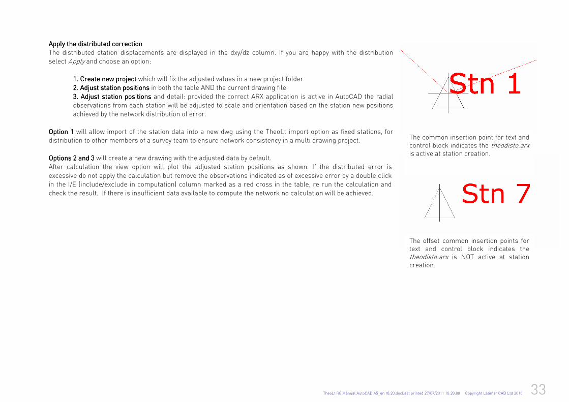
Apply the distributed correction Apply the distributed correction Apply the distributed correction Apply the distributed correction The distributed station displacements are displayed in the dxy/dz column. If you are happy with the distribution select Apply and choose an option:
1. Create new project1. Create new project1. Create new project1. Create new project which will fix the adjusted values in a new project folder 2. Adjust station position2. Adjust station position2. Adjust station position2. Adjust station positionssss in both the table AND the current drawing file
3. Adjust station positions3. Adjust station positions3. Adjust station positions3. Adjust station positions and detail: provided the correct ARX application is active in AutoCAD the radial observations from each station will be adjusted to scale and orientation based on the station new positions achieved by the network distribution of error.
Option 1Option 1Option 1Option 1 will allow import of the station data into a new dwg using the TheoLt import option as fixed stations, for distribution to other members of a survey team to ensure network consistency in a multi drawing project.
Options 2 and 3Options 2 and 3Options 2 and 3Options 2 and 3 will create a new drawing with the adjusted data by default. After calculation the view option will plot the adjusted station positions as shown. If the distributed error is
excessive do not apply the calculation but remove the observations indicated as of excessive error by a double click in the I/E (include/exclude in computation) column marked as a red cross in the table, re run the calculation and check the result. If there is insufficient data available to compute the network no calculation will be achieved.
The common insertion point for text and control block indicates the theodisto.arx is active at station creation.
The offset common insertion points for text and control block indicates the theodisto.arx is NOT active at station creation.
34 TheoLt R8 Manual AutoCAD A5_en r8.20.docLast printed 27/07/2011 10:28:00 Copyright Latimer CAD Ltd 2010
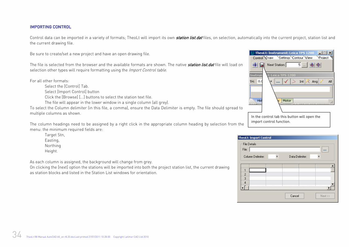
IMPORTING CONTROLIMPORTING CONTROLIMPORTING CONTROLIMPORTING CONTROL
Control data can be imported in a variety of formats; TheoLt will import its own station list.datstation list.datstation list.datstation list.dat files, on selection, automatically into the current project, station list and
the current drawing file. Be sure to create/set a new project and have an open drawing file.
The file is selected from the browser and the available formats are shown. The native station list.datstation list.datstation list.datstation list.dat file will load on selection other types will require formatting using the Import Control table. For all other formats: Select the [Control] Tab.
Select [Import Control] button Click the [Browse] [...] buttons to select the station text file. The file will appear in the lower window in a single column (all grey).
To select the Column delimiter (in this file, a comma), ensure the Data Delimiter is empty. The file should spread to multiple columns as shown.
The column headings need to be assigned by a right click in the appropriate column heading by selection from the menu: the minimum required fields are: Target Stn,
Easting, Northing Height.
As each column is assigned, the background will change from grey. On clicking the [next] option the stations will be imported into both the project station list, the current drawing
as station blocks and listed in the Station List windows for orientation.
In the control tab this button will open the
import control function.
TheoLt R8 Manual AutoCAD A5_en r8.20.docLast printed 27/07/2011 10:28:00 Copyright Latimer CAD Ltd 2010 35
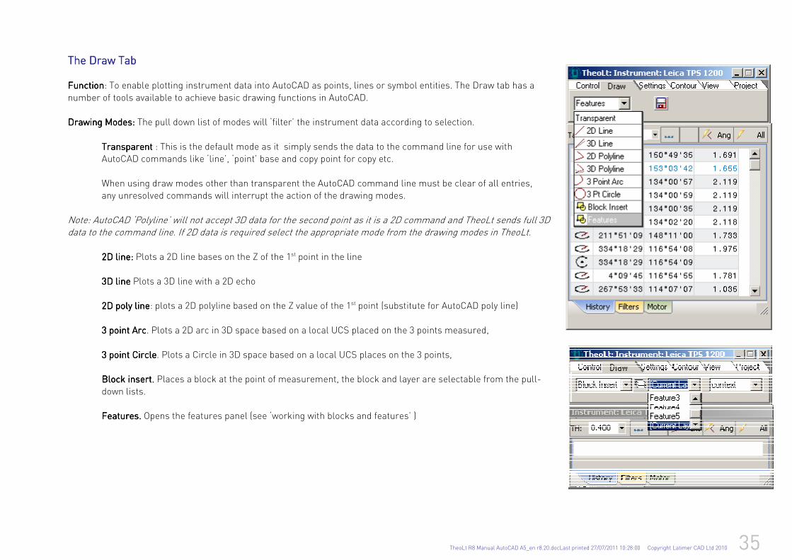
The Draw TabThe Draw TabThe Draw TabThe Draw Tab FunctionFunctionFunctionFunction: To enable plotting instrument data into AutoCAD as points, lines or symbol entities. The Draw tab has a
number of tools available to achieve basic drawing functions in AutoCAD. Drawing Drawing Drawing Drawing MoMoMoModesdesdesdes: : : : The pull down list of modes will ‘filter’ the instrument data according to selection.
TransparentTransparentTransparentTransparent : This is the default mode as it simply sends the data to the command line for use with AutoCAD commands like ‘line’, ‘point’ base and copy point for copy etc.
When using draw modes other than transparent the AutoCAD command line must be clear of all entries, any unresolved commands will interrupt the action of the drawing modes.
Note: AutoCAD ‘Polyline’ will not accept 3D data for the second point as it is a 2D command and TheoLt sends full 3D data to the command line. If 2D data is required select the appropriate mode from the drawing modes in TheoLt. 2D line:2D line:2D line:2D line: Plots a 2D line bases on the Z of the 1st point in the line
3D line3D line3D line3D line Plots a 3D line with a 2D echo 2D poly line2D poly line2D poly line2D poly line: plots a 2D polyline based on the Z value of the 1st point (substitute for AutoCAD poly line)
3 point 3 point 3 point 3 point AAAArcrcrcrc. Plots a 2D arc in 3D space based on a local UCS placed on the 3 points measured,
3 point Circle3 point Circle3 point Circle3 point Circle. Plots a Circle in 3D space based on a local UCS places on the 3 points, Block insertBlock insertBlock insertBlock insert.... Places a block at the point of measurement, the block and layer are selectable from the pull-
down lists. FeaturesFeaturesFeaturesFeatures. . . . Opens the features panel (see ‘working with blocks and features’ )
36 TheoLt R8 Manual AutoCAD A5_en r8.20.docLast printed 27/07/2011 10:28:00 Copyright Latimer CAD Ltd 2010
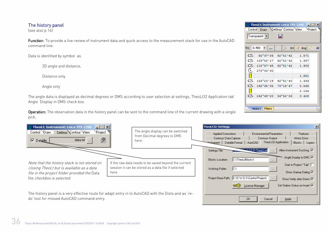
The history panelThe history panelThe history panelThe history panel (see also p 14) FunctionFunctionFunctionFunction: To provide a live review of instrument data and quick access to the measurement stack for use in the AutoCAD command line.
Data is identified by symbol as 3D angle and distance,
Distance only
Angle only The angle data is displayed as decimal degrees or DMS according to user selection at settings, TheoLt32 Application tab’
Angle Display in DMS check box. Operation:Operation:Operation:Operation: The observation data in the history panel can be sent to the command line of the current drawing with a single
pick.
Note that the history stack is not stored on closing TheoLt but is available as a data file in the project folder provided the Data file checkbox is selected. The history panel is a very effective route for adapt entry in to AutoCAD with the Disto and as ‘re-do’ tool for missed AutoCAD command entry.
The angle display can be switched
from Decimal degrees to DMS
here.
If the raw data needs to be saved beyond the current
session it can be stored as a data file if selected
here.
TheoLt R8 Manual AutoCAD A5_en r8.20.docLast printed 27/07/2011 10:28:00 Copyright Latimer CAD Ltd 2010 37
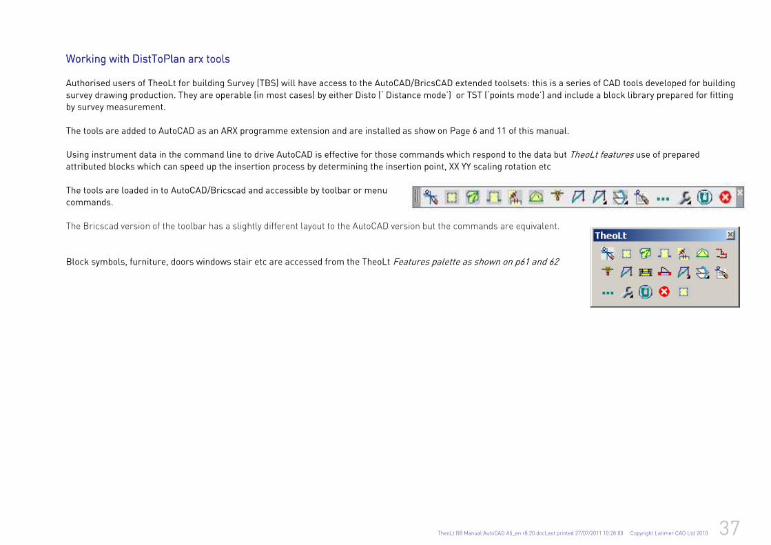
Working with Working with Working with Working with DistToPlan DistToPlan DistToPlan DistToPlan arx arx arx arx toolstoolstoolstools
Authorised users of TheoLt for building Survey (TBS) will have access to the AutoCAD/BricsCAD extended toolsets: this is a series of CAD tools developed for building
survey drawing production. They are operable (in most cases) by either Disto (‘ Distance mode’) or TST (‘points mode’) and include a block library prepared for fitting
by survey measurement.
The tools are added to AutoCAD as an ARX programme extension and are installed as show on Page 6 and 11 of this manual.
Using instrument data in the command line to drive AutoCAD is effective for those commands which respond to the data but TheoLt features use of prepared attributed blocks which can speed up the insertion process by determining the insertion point, XX YY scaling rotation etc
The tools are loaded in to AutoCAD/Bricscad and accessible by toolbar or menu
commands.
The Bricscad version of the toolbar has a slightly different layout to the AutoCAD version but the commands are equivalent.
Block symbols, furniture, doors windows stair etc are accessed from the TheoLt Features palette as shown on p61 and 62
38 TheoLt R8 Manual AutoCAD A5_en r8.20.docLast printed 27/07/2011 10:28:00 Copyright Latimer CAD Ltd 2010
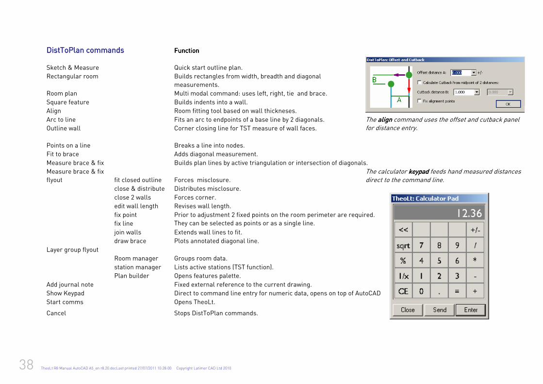
DistToPlan commandDistToPlan commandDistToPlan commandDistToPlan commandssss FunctionFunctionFunctionFunction
Sketch & Measure Quick start outline plan.
Rectangular room Builds rectangles from width, breadth and diagonal
measurements.
Room plan Multi modal command: uses left, right, tie and brace.
Square feature Builds indents into a wall.
Align Room fitting tool based on wall thickneses.
Arc to line Fits an arc to endpoints of a base line by 2 diagonals.
Outline wall Corner closing line for TST measure of wall faces.
Points on a line Breaks a line into nodes.
The alignalignalignalign command uses the offset and cutback panel for distance entry.
Fit to brace Adds diagonal measurement.
Measure brace & fix Builds plan lines by active triangulation or intersection of diagonals.
Measure brace & fix
flyout fit closed outline Forces misclosure.
close & distribute Distributes misclosure.
The calculator keypad keypad keypad keypad feeds hand measured distances direct to the command line.
close 2 walls Forces corner.
edit wall length Revises wall length.
fix point
fix line
Prior to adjustment 2 fixed points on the room perimeter are required.
They can be selected as points or as a single line.
join walls Extends wall lines to fit.
draw brace Plots annotated diagonal line.
Layer group flyout
Room manager Groups room data.
station manager Lists active stations (TST function).
Plan builder Opens features palette.
Add journal note Fixed external reference to the current drawing.
Show Keypad Direct to command line entry for numeric data, opens on top of AutoCAD
Start comms Opens TheoLt.
Cancel Stops DistToPlan commands.
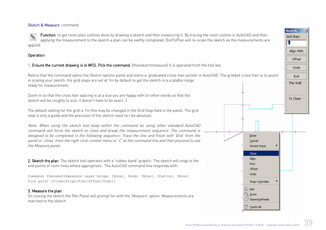
TheoLt R8 Manual AutoCAD A5_en r8.20.docLast printed 27/07/2011 10:28:00 Copyright Latimer CAD Ltd 2010 39
Sketch &Sketch &Sketch &Sketch & MeasureMeasureMeasureMeasure command
FunctionFunctionFunctionFunction: to get room plan outlines done by drawing a sketch and then measuring it. By tracing the room outline in AutoCAD and then
applying the measurement to the sketch a plan can be swiftly completed. DistToPlan will re-scale the sketch as the measurements are applied.
OperationOperationOperationOperation 1. . . . Ensure the current drawing is in WCS. Ensure the current drawing is in WCS. Ensure the current drawing is in WCS. Ensure the current drawing is in WCS. Pick the commandPick the commandPick the commandPick the command. . . . (theosketchmeasure) It is operated from the tool bar,
Notice that the command opens the Sketch options panel and starts a ‘graduated cross-hair pointer in AutoCAD. The gridded cross-hair is to assist in scaling your sketch: the grid steps are set at 1m by default to get the sketch in a scalable range
ready for measurement. Zoom in so that the cross hair spacing is at a size you are happy with (in other words so that the
sketch will be roughly to size, it doesn’t have to be exact…] The default setting for the grid is 1m this may be changed in the Grid Step field in the panel. The grid
step is only a guide and the precision of the sketch need no t be absolute. Note: When using the sketch tool keep within the command as using other standard AutoCAD command will force the sketch to close and break the measurement sequence. The command is designed to be completed in the following sequence: Trace the line and finish with ‘End‘ from the panel or ‘close’ from the right click context menu or ‘C’ at the command line and then proceed to use the Measure panel.
2. Sketch2. Sketch2. Sketch2. Sketch the plan the plan the plan the plan. The sketch tool operates with a ‘rubber band’ graphic. The sketch will snap to the end points of room lines where appropriate: The AutoCAD command line responds with:
Command: theosketchmeasure Layer Group: [None]. Roo m: [None]. Station: [None]
Pick point [Close/Align/Prev/Offset/Undo]:
3.3.3.3. Measure the plan Measure the plan Measure the plan Measure the plan. On closing the sketch the Pen Panel will prompt for with the ‘Measure’ option. Measurements are matched to the sketch
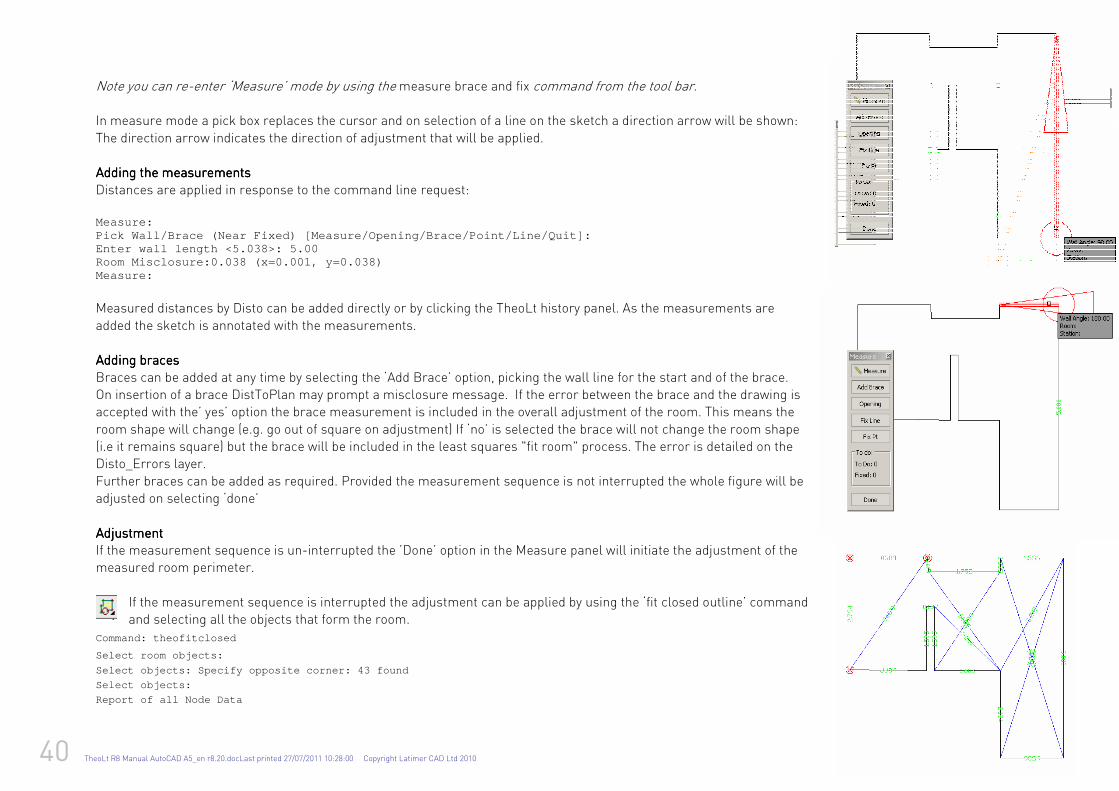
40 TheoLt R8 Manual AutoCAD A5_en r8.20.docLast printed 27/07/2011 10:28:00 Copyright Latimer CAD Ltd 2010
Note you can re-enter ‘Measure’ mode by using the measure brace and fix command from the tool bar. In measure mode a pick box replaces the cursor and on selection of a line on the sketch a direction arrow will be shown:
The direction arrow indicates the direction of adjustment that will be applied. Adding the measurementsAdding the measurementsAdding the measurementsAdding the measurements
Distances are applied in response to the command line request: Measure: Pick Wall/Brace (Near Fixed) [Measure/Opening/Brace /Point/Line/Quit]: Enter wall length <5.038>: 5.00 Room Misclosure:0.038 (x=0.001, y=0.038) Measure:
Measured distances by Disto can be added directly or by clicking the TheoLt history panel. As the measurements are
added the sketch is annotated with the measurements. Adding bracesAdding bracesAdding bracesAdding braces
Braces can be added at any time by selecting the ‘Add Brace’ option, picking the wall line for the start and of the brace. On insertion of a brace DistToPlan may prompt a misclosure message. If the error between the brace and the drawing is accepted with the’ yes’ option the brace measurement is included in the overall adjustment of the room. This means the
room shape will change (e.g. go out of square on adjustment) If ‘no’ is selected the brace will not change the room shape (i.e it remains square) but the brace will be included in the least squares "fit room" process. The error is detailed on the Disto_Errors layer.
Further braces can be added as required. Provided the measurement sequence is not interrupted the whole figure will be adjusted on selecting ‘done’
AdjustmentAdjustmentAdjustmentAdjustment If the measurement sequence is un-interrupted the ’Done’ option in the Measure panel will initiate the adjustment of the measured room perimeter.
If the measurement sequence is interrupted the adjustment can be applied by using the ‘fit closed outline’ command and selecting all the objects that form the room.
Command: theofitclosed
Select room objects:
Select objects: Specify opposite corner: 43 found
Select objects:
Report of all Node Data
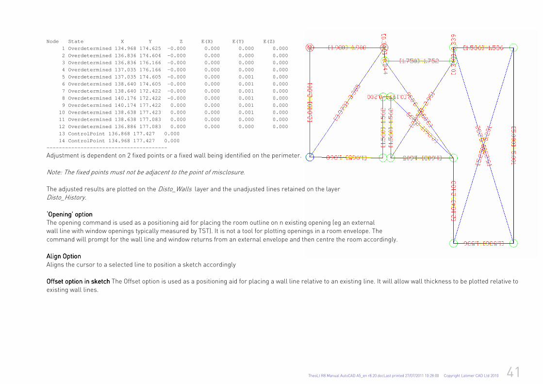
TheoLt R8 Manual AutoCAD A5_en r8.20.docLast printed 27/07/2011 10:28:00 Copyright Latimer CAD Ltd 2010 41
Node State X Y Z E (X) E(Y) E(Z)
1 Overdetermined 134.968 174.625 -0.000 0.000 0.000 0.000
2 Overdetermined 136.836 174.604 -0.000 0.000 0.000 0.000
3 Overdetermined 136.836 176.166 -0.000 0.000 0.000 0.000
4 Overdetermined 137.035 176.166 -0.000 0.000 0.000 0.000
5 Overdetermined 137.035 174.605 -0.000 0.000 0.001 0.000
6 Overdetermined 138.640 174.605 -0.000 0.000 0.001 0.000
7 Overdetermined 138.640 172.422 -0.000 0.000 0.001 0.000
8 Overdetermined 140.176 172.422 -0.000 0.000 0.001 0.000
9 Overdetermined 140.174 177.422 0.000 0.000 0.001 0.000
10 Overdetermined 138.638 177.423 0.000 0.000 0.001 0.000
11 Overdetermined 138.638 177.083 0.000 0.000 0.000 0.000
12 Overdetermined 136.886 177.083 0.000 0.000 0.000 0.000
13 ControlPoint 136.868 177.427 0.000
14 ControlPoint 134.968 177.427 0.000
---------------------------------------
Adjustment is dependent on 2 fixed points or a fixed wall being identified on the perimeter.
Note: The fixed points must not be adjacent to the point of misclosure.
The adjusted results are plotted on the Disto_Walls layer and the unadjusted lines retained on the layer Disto_History.
‘Opening’ option‘Opening’ option‘Opening’ option‘Opening’ option The opening command is used as a positioning aid for placing the room outline on n existing opening (eg an external wall line with window openings typically measured by TST). It is not a tool for plotting openings in a room envelope. The
command will prompt for the wall line and window returns from an external envelope and then centre the room accordingly. Align OptionAlign OptionAlign OptionAlign Option
Aligns the cursor to a selected line to position a sketch accordingly Offset option in sketch Offset option in sketch Offset option in sketch Offset option in sketch The Offset option is used as a positioning aid for placing a wall line relative to an existing line. It will allow wall thickness to be plotted relative to
existing wall lines.

42 TheoLt R8 Manual AutoCAD A5_en r8.20.docLast printed 27/07/2011 10:28:00 Copyright Latimer CAD Ltd 2010
Rectangular roomRectangular roomRectangular roomRectangular room command FunctionFunctionFunctionFunction: to get room plan plans done by developing rectangles as the base geometry prior to completion by use of the rectangular feature command.
OperationOperationOperationOperation
Pick the commandPick the commandPick the commandPick the command. . . . (THEODROOM) It is operated from the tool bar, the AutoCAD command line will respond with: Enter Length of Room:
When the distance is entered the next prompt is:
Enter Width of Room:
When this value is entered a further prompt requests a brace:
Enter Diagonal of Room. <Enter> to ignore:
Which can be skipped. The sequence is repeated for averaging if required, if not the requests can be skipped with an enter reply. The command line dialogue will then request:
Place the room
a temporary graphic of the rectangle is attached to the cursor in the graphics area; it can be paced with a pick.
The command line will now request alignment of the rectangle; this should be cancelled with ‘esc’ for the first room as there are no object to align it to!
Moving to the next room the command can be repeated and the ‘align’ applied on placing the room in the drawing.
The align command is also available as a stand alone command which can be used on any selection of objects.
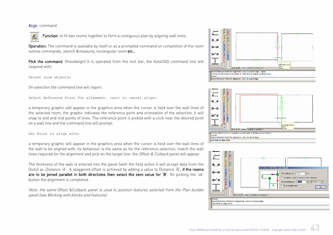
TheoLt R8 Manual AutoCAD A5_en r8.20.docLast printed 27/07/2011 10:28:00 Copyright Latimer CAD Ltd 2010 43
AlignAlignAlignAlign command FunctionFunctionFunctionFunction: to fit two rooms together to form a contiguous plan by aligning wall lines.
OperatOperatOperatOperationionionion: : : : The command is available by itself or as a prompted command on completion of the room outline commands, sketch &measure, , , , rectangular room etc.. etc.. etc.. etc..
Pick the commandPick the commandPick the commandPick the command. . . . (theodalign) It is operated from the tool bar, the AutoCAD command line will respond with:
Select room objects:
On selection the command line will report: Select Reference Point for alignment. <esc> to canc el align:
a temporary graphic will appear in the graphics area when the cursor is held over the wall lines of the selected room, the graphic indicates the reference point and orientation of the selection, it will
snap to end and mid points of lines. The reference point is picked with a click near the desired point on a wall line and the command line will prompt:
Get Point to align with:
a temporary graphic will appear in the graphics area when the cursor is held over the wall lines of
the wall to be aligned with, its behaviour is the same as for the reference selection, match the wall lines required for the alignment and pick on the target line: the Offset & Cutback panel will appear:
The thickness of the wall is entered into the panel (with the field active it will accept data from the Disto) as Distance ‘A’. A staggered offset is achieved by adding a value to Distance ‘B’, if the ro, if the ro, if the ro, if the rooms oms oms oms are to be joined parallel in both directions then select the zero value for ‘B’are to be joined parallel in both directions then select the zero value for ‘B’are to be joined parallel in both directions then select the zero value for ‘B’are to be joined parallel in both directions then select the zero value for ‘B’. On picking the ‘ok’
button the alignment is completed. Note: the same Offset &Cutback panel is used to position features selected from the Plan builder panel (see Working with blocks and features)
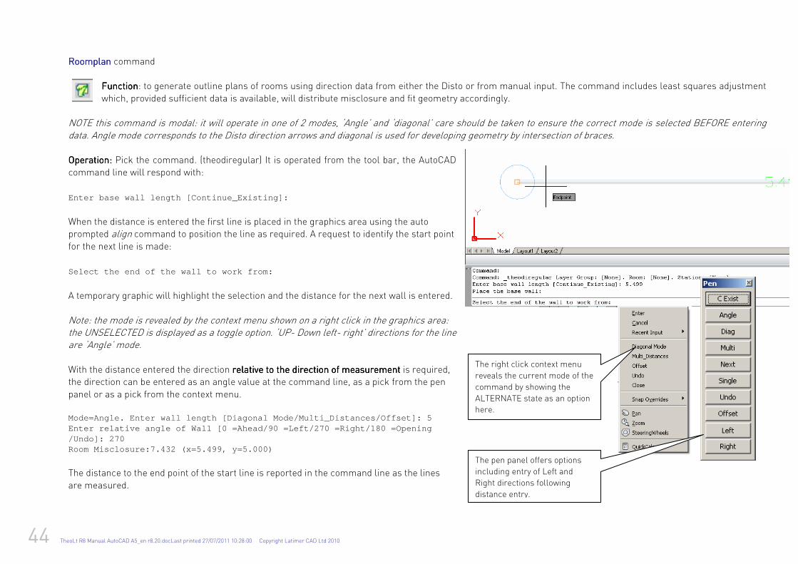
44 TheoLt R8 Manual AutoCAD A5_en r8.20.docLast printed 27/07/2011 10:28:00 Copyright Latimer CAD Ltd 2010
Roomplan Roomplan Roomplan Roomplan command FunctionFunctionFunctionFunction: to generate outline plans of rooms using direction data from either the Disto or from manual input. The command includes least squares adjustment
which, provided sufficient data is available, will distribute misclosure and fit geometry accordingly. NOTE this command is modal: it will operate in one of 2 modes, ‘Angle’ and ‘diagonal’ care should be taken to ensure the correct mode is selected BEFORE entering data. Angle mode corresponds to the Disto direction arrows and diagonal is used for developing geometry by intersection of braces. OperationOperationOperationOperation: : : : Pick the command. (theodiregular) It is operated from the tool bar, the AutoCAD
command line will respond with: Enter base wall length [Continue_Existing]:
When the distance is entered the first line is placed in the graphics area using the auto prompted align command to position the line as required. A request to identify the start point
for the next line is made: Select the end of the wall to work from:
A temporary graphic will highlight the selection and the distance for the next wall is entered.
Note: the mode is revealed by the context menu shown on a right click in the graphics area: the UNSELECTED is displayed as a toggle option. ‘UP- Down left- right’ directions for the line are ‘Angle’ mode. With the distance entered the direction relative to the direction of measurementrelative to the direction of measurementrelative to the direction of measurementrelative to the direction of measurement is required, the direction can be entered as an angle value at the command line, as a pick from the pen
panel or as a pick from the context menu. Mode=Angle. Enter wall length [Diagonal Mode/Multi_ Distances/Offset]: 5 Enter relative angle of Wall [0 =Ahead/90 =Left/270 =Right/180 =Opening /Undo]: 270 Room Misclosure:7.432 (x=5.499, y=5.000)
The distance to the end point of the start line is reported in the command line as the lines
are measured.
The right click context menu
reveals the current mode of the
command by showing the
ALTERNATE state as an option
here.
The pen panel offers options
including entry of Left and
Right directions following
distance entry.
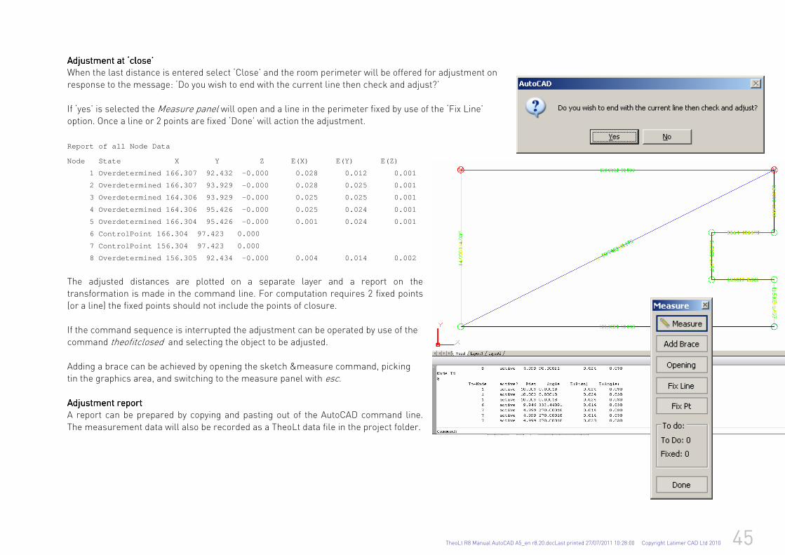
TheoLt R8 Manual AutoCAD A5_en r8.20.docLast printed 27/07/2011 10:28:00 Copyright Latimer CAD Ltd 2010 45
Adjustment at ‘close’Adjustment at ‘close’Adjustment at ‘close’Adjustment at ‘close’ When the last distance is entered select ‘Close’ and the room perimeter will be offered for adjustment on response to the message: ‘Do you wish to end with the current line then check and adjust?’
If ‘yes’ is selected the Measure panel will open and a line in the perimeter fixed by use of the ‘Fix Line’ option. Once a line or 2 points are fixed ‘Done’ will action the adjustment.
Report of all Node Data
Node State X Y Z E (X) E(Y) E(Z)
1 Overdetermined 166.307 92.432 -0.000 0.028 0.012 0.001
2 Overdetermined 166.307 93.929 -0.000 0.028 0.025 0.001
3 Overdetermined 164.306 93.929 -0.000 0.025 0.025 0.001
4 Overdetermined 164.306 95.426 -0.000 0.025 0.024 0.001
5 Overdetermined 166.304 95.426 -0.000 0.001 0.024 0.001
6 ControlPoint 166.304 97.423 0.000
7 ControlPoint 156.304 97.423 0.000
8 Overdetermined 156.305 92.434 -0.000 0.004 0.014 0.002
The adjusted distances are plotted on a separate layer and a report on the transformation is made in the command line. For computation requires 2 fixed points (or a line) the fixed points should not include the points of closure.
If the command sequence is interrupted the adjustment can be operated by use of the command theofitclosed and selecting the object to be adjusted. Adding a brace can be achieved by opening the sketch &measure command, picking tin the graphics area, and switching to the measure panel with esc. Adjustment reportAdjustment reportAdjustment reportAdjustment report A report can be prepared by copying and pasting out of the AutoCAD command line.
The measurement data will also be recorded as a TheoLt data file in the project folder.
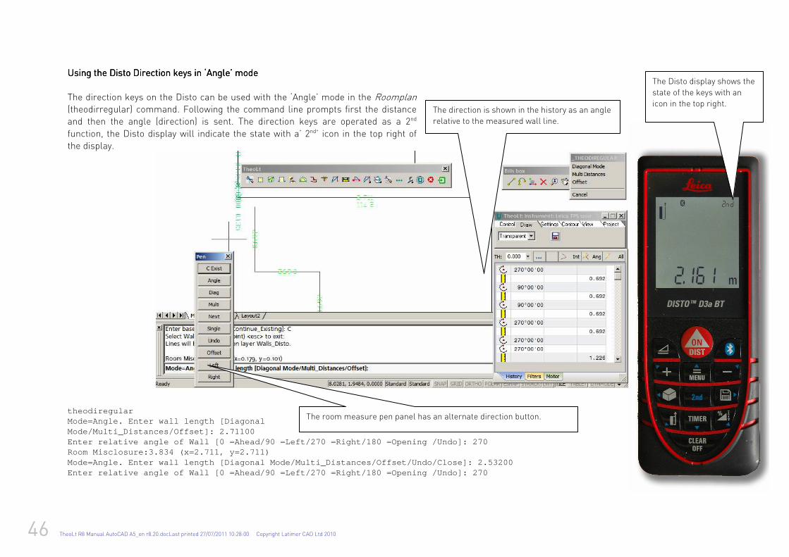
46 TheoLt R8 Manual AutoCAD A5_en r8.20.docLast printed 27/07/2011 10:28:00 Copyright Latimer CAD Ltd 2010
Using the DiUsing the DiUsing the DiUsing the Dissssto Direction keysto Direction keysto Direction keysto Direction keys in ‘Angle’ mode in ‘Angle’ mode in ‘Angle’ mode in ‘Angle’ mode
The direction keys on the Disto can be used with the ‘Angle’ mode in the Roomplan (theodirregular) command. Following the command line prompts first the distance and then the angle (direction) is sent. The direction keys are operated as a 2nd
function, the Disto display will indicate the state with a’ 2nd’ icon in the top right of the display.
theodiregular Mode=Angle. Enter wall length [Diagonal Mode/Multi_Distances/Offset]: 2.71100 Enter relative angle of Wall [0 =Ahead/90 =Left/270 =Right/180 =Opening /Undo]: 270 Room Misclosure:3.834 (x=2.711, y=2.711) Mode=Angle. Enter wall length [Diagonal Mode/Multi_ Distances/Offset/Undo/Close]: 2.53200 Enter relative angle of Wall [0 =Ahead/90 =Left/270 =Right/180 =Opening /Undo]: 270
The Disto display shows the
state of the keys with an
icon in the top right. The direction is shown in the history as an angle
relative to the measured wall line.
The room measure pen panel has an alternate direction button.
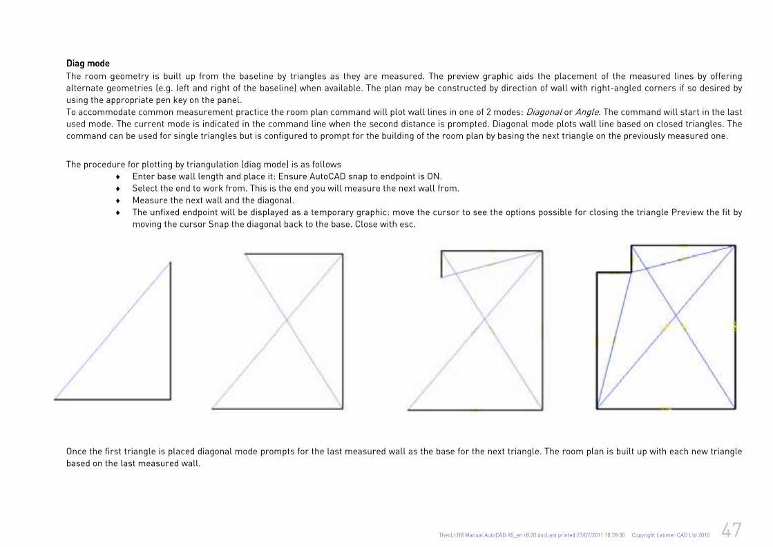
TheoLt R8 Manual AutoCAD A5_en r8.20.docLast printed 27/07/2011 10:28:00 Copyright Latimer CAD Ltd 2010 47
Diag modeDiag modeDiag modeDiag mode
The room geometry is built up from the baseline by triangles as they are measured. The preview graphic aids the placement of the measured lines by offering
alternate geometries (e.g. left and right of the baseline) when available. The plan may be constructed by direction of wall with right-angled corners if so desired by
using the appropriate pen key on the panel.
To accommodate common measurement practice the room plan command will plot wall lines in one of 2 modes: Diagonal or Angle. The command will start in the last
used mode. The current mode is indicated in the command line when the second distance is prompted. Diagonal mode plots wall line based on closed triangles. The
command can be used for single triangles but is configured to prompt for the building of the room plan by basing the next triangle on the previously measured one.
The procedure for plotting by triangulation (diag mode) is as follows
♦ Enter base wall length and place it: Ensure AutoCAD snap to endpoint is ON.
♦ Select the end to work from. This is the end you will measure the next wall from.
♦ Measure the next wall and the diagonal.
♦ The unfixed endpoint will be displayed as a temporary graphic: move the cursor to see the options possible for closing the triangle Preview the fit by
moving the cursor Snap the diagonal back to the base. Close with esc.
Once the first triangle is placed diagonal mode prompts for the last measured wall as the base for the next triangle. The room plan is built up with each new triangle
based on the last measured wall.
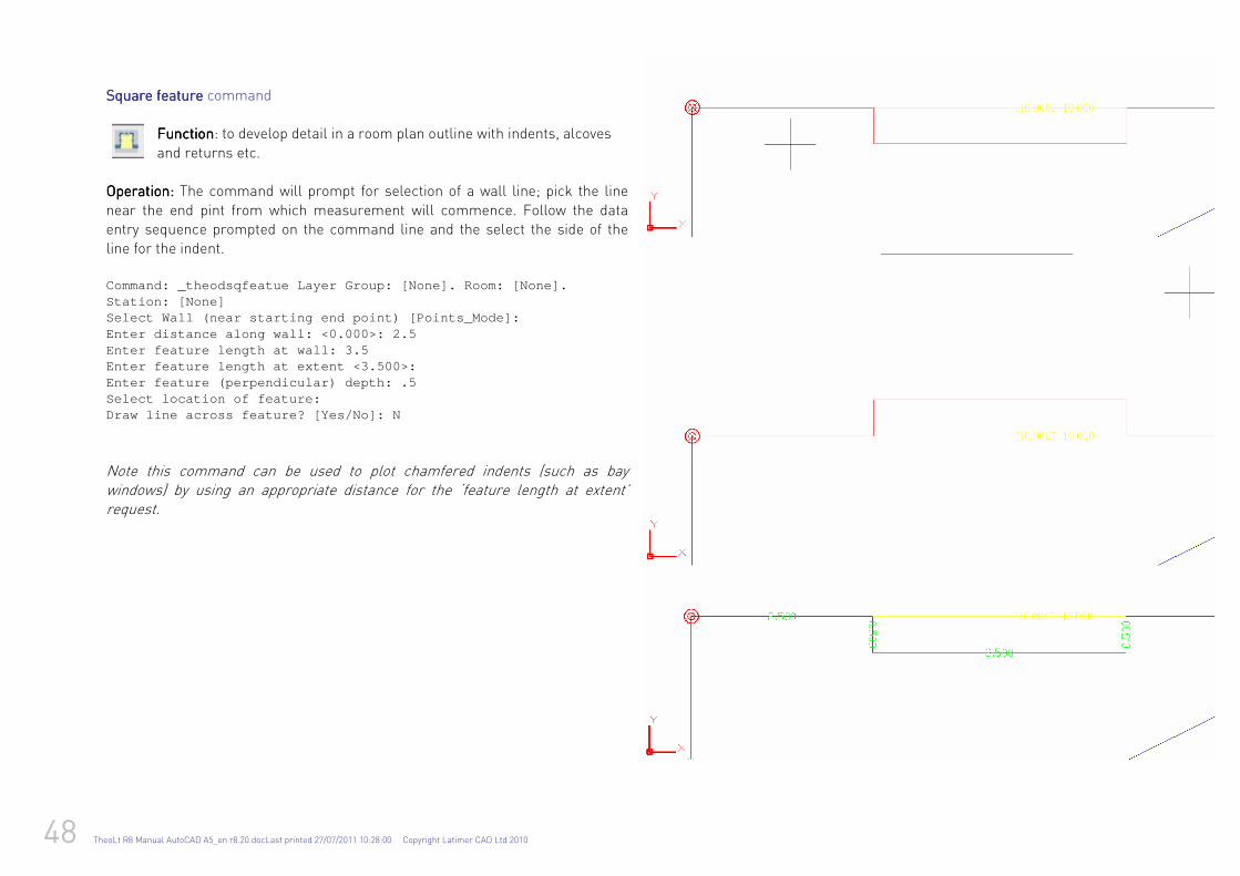
48 TheoLt R8 Manual AutoCAD A5_en r8.20.docLast printed 27/07/2011 10:28:00 Copyright Latimer CAD Ltd 2010
SSSSquare feature quare feature quare feature quare feature command FunctionFunctionFunctionFunction: to develop detail in a room plan outline with indents, alcoves
and returns etc. OperationOperationOperationOperation: : : : The command will prompt for selection of a wall line; pick the line
near the end pint from which measurement will commence. Follow the data entry sequence prompted on the command line and the select the side of the line for the indent.
Command: _theodsqfeatue Layer Group: [None]. Room: [None]. Station: [None] Select Wall (near starting end point) [Points_Mode] : Enter distance along wall: <0.000>: 2.5 Enter feature length at wall: 3.5 Enter feature length at extent <3.500>: Enter feature (perpendicular) depth: .5 Select location of feature: Draw line across feature? [Yes/No]: N
Note this command can be used to plot chamfered indents (such as bay windows) by using an appropriate distance for the ‘feature length at extent’ request.
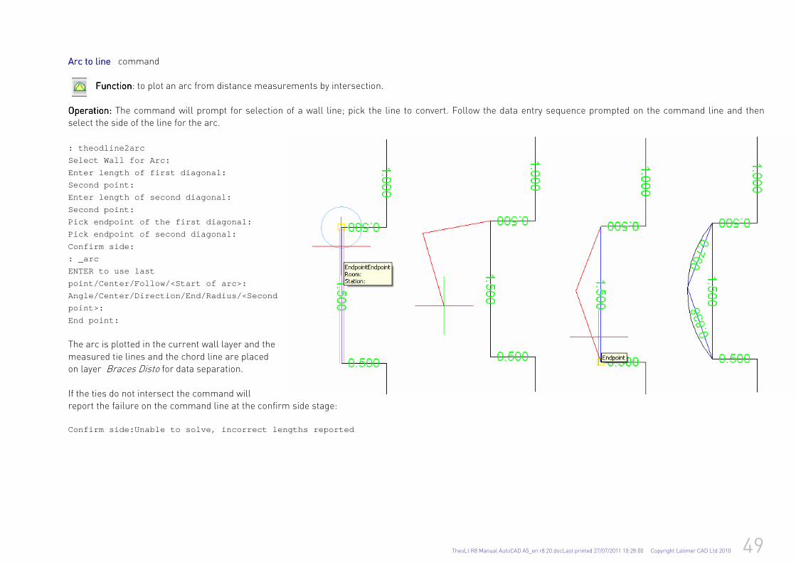
TheoLt R8 Manual AutoCAD A5_en r8.20.docLast printed 27/07/2011 10:28:00 Copyright Latimer CAD Ltd 2010 49
Arc to line Arc to line Arc to line Arc to line command FunctionFunctionFunctionFunction: to plot an arc from distance measurements by intersection.
OperationOperationOperationOperation: : : : The command will prompt for selection of a wall line; pick the line to convert. Follow the data entry sequence prompted on the command line and then select the side of the line for the arc.
: theodline2arc
Select Wall for Arc:
Enter length of first diagonal:
Second point:
Enter length of second diagonal:
Second point:
Pick endpoint of the first diagonal:
Pick endpoint of second diagonal:
Confirm side:
: _arc
ENTER to use last
point/Center/Follow/<Start of arc>:
Angle/Center/Direction/End/Radius/<Second
point>:
End point:
The arc is plotted in the current wall layer and the
measured tie lines and the chord line are placed on layer Braces Disto for data separation.
If the ties do not intersect the command will report the failure on the command line at the confirm side stage: Confirm side:Unable to solve, incorrect lengths rep orted
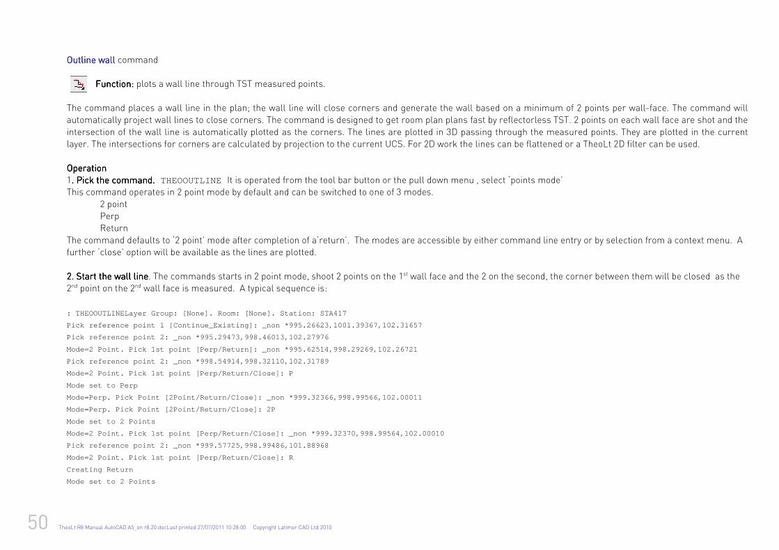
50 TheoLt R8 Manual AutoCAD A5_en r8.20.docLast printed 27/07/2011 10:28:00 Copyright Latimer CAD Ltd 2010
Outline wallOutline wallOutline wallOutline wall command Function: Function: Function: Function: plots a wall line through TST measured points.
The command places a wall line in the plan; the wall line will close corners and generate the wall based on a minimum of 2 points per wall-face. The command will automatically project wall lines to close corners. The command is designed to get room plan plans fast by reflectorless TST. 2 points on each wall face are shot and the
intersection of the wall line is automatically plotted as the corners. The lines are plotted in 3D passing through the measured points. They are plotted in the current layer. The intersections for corners are calculated by projection to the current UCS. For 2D work the lines can be flattened or a TheoLt 2D filter can be used. OperationOperationOperationOperation 1. Pick the command. Pick the command. Pick the command. Pick the command.... THEOOUTLINE It is operated from the tool bar button or the pull down menu , select ‘points mode’ This command operates in 2 point mode by default and can be switched to one of 3 modes.
2 point Perp Return
The command defaults to ‘2 point’ mode after completion of a‘return’. The modes are accessible by either command line entry or by selection from a context menu. A further ‘close’ option will be available as the lines are plotted.
2. Start the wall line2. Start the wall line2. Start the wall line2. Start the wall line. The commands starts in 2 point mode, shoot 2 points on the 1st wall face and the 2 on the second, the corner between them will be closed as the 2nd point on the 2nd wall face is measured. A typical sequence is:
: THEOOUTLINELayer Group: [None]. Room: [None]. Sta tion: STA417
Pick reference point 1 [Continue_Existing]: _non *9 95.26623,1001.39367,102.31657
Pick reference point 2: _non *995.29473,998.46013,1 02.27976
Mode=2 Point. Pick 1st point [Perp/Return]: _non *9 95.62514,998.29269,102.26721
Pick reference point 2: _non *998.54914,998.32110,1 02.31789
Mode=2 Point. Pick 1st point [Perp/Return/Close]: P
Mode set to Perp
Mode=Perp. Pick Point [2Point/Return/Close]: _non * 999.32366,998.99566,102.00011
Mode=Perp. Pick Point [2Point/Return/Close]: 2P
Mode set to 2 Points
Mode=2 Point. Pick 1st point [Perp/Return/Close]: _ non *999.32370,998.99564,102.00010
Pick reference point 2: _non *999.57725,998.99486,1 01.88968
Mode=2 Point. Pick 1st point [Perp/Return/Close]: R
Creating Return
Mode set to 2 Points

TheoLt R8 Manual AutoCAD A5_en r8.20.docLast printed 27/07/2011 10:28:00 Copyright Latimer CAD Ltd 2010 51
Mode=2 Point. Pick 1st point [Perp/Return/Close]: _ non
*999.85462,998.46253,102.00367
Pick reference point 2: _non *1001.32601,998.47234, 102.20282
Mode=2 Point. Pick 1st point [Perp/Return/Close]: _ non
*1001.50693,998.53862,102.24471
Pick reference point 2: _non *1001.47444,1001.58822 ,102.28590
Mode=2 Point. Pick 1st point [Perp/Return/Close]: _ non
*1001.39921,1001.63480,102.28117
Pick reference point 2: _non *999.59884,1001.63569, 101.77969
Mode=2 Point. Pick 1st point [Perp/Return/Close]: P
Mode set to Perp
Mode=Perp. Pick Point [2Point/Return/Close]: _non
*999.55066,1000.99736,101.72265
Mode=Perp. Pick Point [2Point/Return/Close]: 2P
Mode set to 2 Points
Mode=2 Point. Pick 1st point [Perp/Return/Close]: _ non
*999.55066,1000.99736,101.72263
Pick reference point 2: _non *999.30000,1000.98619, 101.73385
Mode=2 Point. Pick 1st point [Perp/Return/Close]: R
Mode=2 Point. Pick 1st point [Perp/Return/Close]: C
Depending on the direction (inward a or outward) of the hidden corner, PERP and RETURN will plot lines at right angles to the measured face.
A’ Perp’ measurement will begin on a corner and a RETURN measurement AFTER one.
CLOSE will return the wall line to intersect with the starting line and exit
the command.
Note that ‘2 point’ needs to be reselected after using ‘Perp’ and that it is
automatically reset after closing a ‘Return’ corner.
Measurement
begins with ‘2 point’
mode
The wall line will be
closed when point 4
is measured. This point is
measured as a
‘Return’
This point is a
PERP.
This point is
measured in Perp
mode.
The mode is
returned to ‘2 point’
for this point
On completion the
CLOSE option
forms the last
This point restarts
‘2 point’ mode.
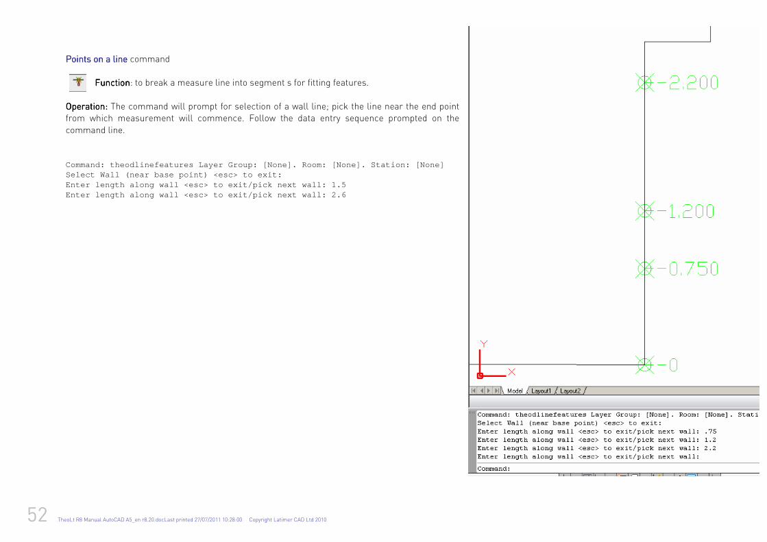
52 TheoLt R8 Manual AutoCAD A5_en r8.20.docLast printed 27/07/2011 10:28:00 Copyright Latimer CAD Ltd 2010
Points on a line Points on a line Points on a line Points on a line command FunctionFunctionFunctionFunction: to break a measure line into segment s for fitting features.
OperationOperationOperationOperation: : : : The command will prompt for selection of a wall line; pick the line near the end point from which measurement will commence. Follow the data entry sequence prompted on the
command line. Command: theodlinefeatures Layer Group: [None]. Roo m: [None]. Station: [None] Select Wall (near base point) <esc> to exit: Enter length along wall <esc> to exit/pick next wal l: 1.5 Enter length along wall <esc> to exit/pick next wal l: 2.6
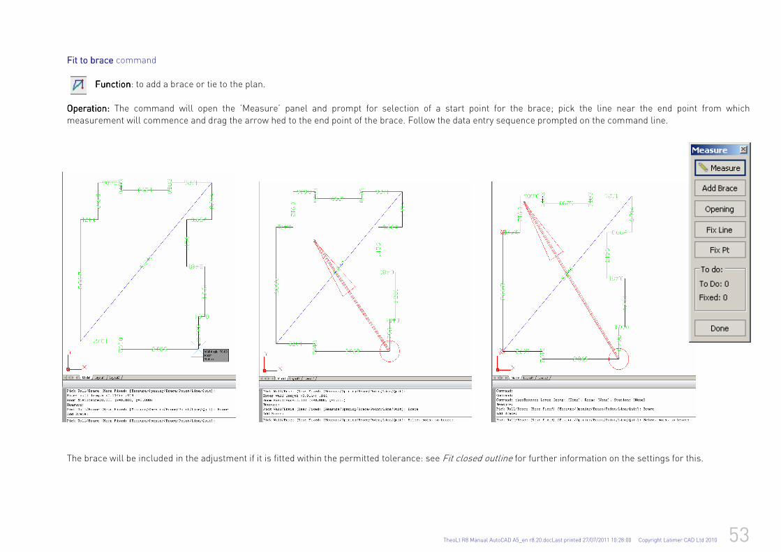
TheoLt R8 Manual AutoCAD A5_en r8.20.docLast printed 27/07/2011 10:28:00 Copyright Latimer CAD Ltd 2010 53
Fit to braceFit to braceFit to braceFit to brace command FunctionFunctionFunctionFunction: to add a brace or tie to the plan.
OperationOperationOperationOperation: : : : The command will open the ’Measure’ panel and prompt for selection of a start point for the brace; pick the line near the end point from which measurement will commence and drag the arrow hed to the end point of the brace. Follow the data entry sequence prompted on the command line.
The brace will be included in the adjustment if it is fitted within the permitted tolerance: see Fit closed outline for further information on the settings for this.
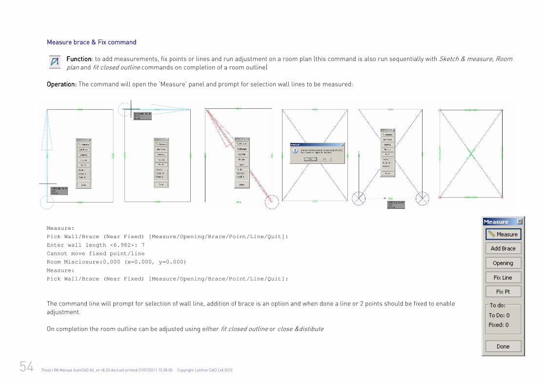
54 TheoLt R8 Manual AutoCAD A5_en r8.20.docLast printed 27/07/2011 10:28:00 Copyright Latimer CAD Ltd 2010
Measure brace & Fix Measure brace & Fix Measure brace & Fix Measure brace & Fix commandcommandcommandcommand
FunctionFunctionFunctionFunction: to add measurements, fix points or lines and run adjustment on a room plan (this command is also run sequentially with Sketch & measure, Room plan and fit closed outline commands on completion of a room outline)
OperationOperationOperationOperation: : : : The command will open the ’Measure’ panel and prompt for selection wall lines to be measured:
Measure:
Pick Wall/Brace (Near Fixed) [Measure/Opening/Brace /Point/Line/Quit]:
Enter wall length <6.982>: 7
Cannot move fixed point/line
Room Misclosure:0.000 (x=0.000, y=0.000)
Measure:
Pick Wall/Brace (Near Fixed) [Measure/Opening/Brace /Point/Line/Quit]:
The command line will prompt for selection of wall line, addition of brace is an option and when done a line or 2 points should be fixed to enable adjustment.
On completion the room outline can be adjusted using either fit closed outline or close &distibute
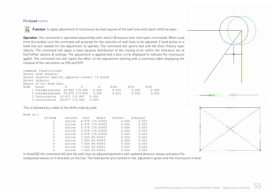
TheoLt R8 Manual AutoCAD A5_en r8.20.docLast printed 27/07/2011 10:28:00 Copyright Latimer CAD Ltd 2010 55
Fit Fit Fit Fit closed closed closed closed outline FunctionFunctionFunctionFunction: to apply adjustment of misclosure by least squres of the wall lines and report shifts by layer.
OperationOperationOperationOperation: this command is opertated sequentially with sketch &measure and room plan commands. When used from the toolbar icon the command will propmpt for the selection of wall lines to be adjusted. 2 fixed points or a
fixed line are needed for the adjustment to operate. The command will ignore text and the Disto History layer objects. The command will apply a least squares distribution of the closing error within the tolerance set at DistToPlan options & settings. The adjustment is applied and a blue circle displayed to indicate the misclosure
gap(s). The command line will report the effect of the adjustment starting with a summary table displaying the residual of the calculation as E(X) and E(Y). Command: theofitclosed Select room objects: Select objects: Specify opposite corner: 14 found Select objects: Report of all Node Data Node State X Y Z E (X) E(Y) E(Z) 1 Overdetermined 28.869 179.860 0.000 0.001 0.002 0.000 2 Overdetermined 23.870 179.830 0.000 0.001 0.002 0.000 3 ControlPoint 23.877 172.847 0.000 4 ControlPoint 28.877 172.848 0.000
This is followed by a table of the shifts node by node. Node Id 1 To-Node active? Dist Angle E(Dist) E(Angle) 2 active 4.978 179.63925 0.004 0.003 2 active 4.978 179.63925 0.004 0.003 2 active 4.978 179.63925 0.004 0.003 2 active 4.978 179.63925 0.004 0.003 2 active 4.978 179.63925 0.006 0.003 4 active 7.000 89.93453 0.004 0.003 4 active 7.000 89.93453 0.004 0.003 4 active 7.000 89.93453 0.004 0.003 4 active 7.000 89.93453 0.004 0.003 4 active 7.000 89.93453 0.004 0.003
In AutoCAD the command will plot the wall lines as adjusted geometry with updated distance values and place the unadjusted values on in brackets on the line. The fixed points are marked in red, adjusted in green and the misclosure in blue.
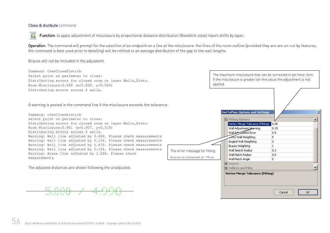
56 TheoLt R8 Manual AutoCAD A5_en r8.20.docLast printed 27/07/2011 10:28:00 Copyright Latimer CAD Ltd 2010
Close & distibute Close & distibute Close & distibute Close & distibute command FunctionFunctionFunctionFunction: to apply adjustment of misclosure by proportional distance distribution (Bowditch style) report shifts by layer.
OperationOperationOperationOperation: The command will prompt for the selection of an endpoint on a line at the misclosure: the lines of the room outline (provided they are are un-cut by features; the command is best used prior to detailing) will be refitted to an average distribution of the gap to the wall lengths.
Braces will not be included in the adjustemt. Command: theoCloseDistrib
Select point on perimeter to close:
Distributing errors for closed room on layer Walls_ Disto.
Room Misclosure:0.069 (x=0.068, y=0.004)
Distributing errors across 4 walls.
A warning is posted in the command line if the misclosure exceeds the tolerance:
Command: theoCloseDistrib Select point on perimeter to close: Distributing errors for closed room on layer Walls_ Disto. Room Misclosure:0.961 (x=0.907, y=0.319) Distributing errors across 4 walls. Warning: Wall line adjusted by 0.408. Please check measurements Warning: Wall line adjusted by 0.154. Please check measurements Warning: Wall line adjusted by 0.470. Please check measurements Warning: Wall line adjusted by 0.154. Please check measurements Warning: Brace line adjusted by 1.268. Please check measurements The adjusted distances are shown following the unadjusted.
The maximum misclosure that can be corrected is set here: 5cm.
If the misclosure is greater tan this value the adjustment is not
applied.
The error message for fitting
braces is triggered at: 15cm
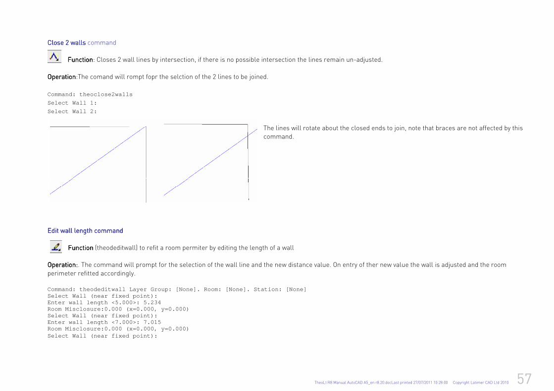
TheoLt R8 Manual AutoCAD A5_en r8.20.docLast printed 27/07/2011 10:28:00 Copyright Latimer CAD Ltd 2010 57
Close 2 wallsClose 2 wallsClose 2 wallsClose 2 walls command FunctionFunctionFunctionFunction: Closes 2 wall lines by intersection, if there is no possible intersection the lines remain un-adjusted.
OperationOperationOperationOperation:The comand will rompt fopr the selction of the 2 lines to be joined.
Command: theoclose2walls
Select Wall 1:
Select Wall 2:
The lines will rotate about the closed ends to join, note that braces are not affected by this command.
Edit wall length commandEdit wall length commandEdit wall length commandEdit wall length command
FunctionFunctionFunctionFunction (theodeditwall) to refit a room permiter by editing the length of a wall
OperationOperationOperationOperation::::. The command will prompt for the selection of the wall line and the new distance value. On entry of ther new value the wall is adjusted and the room
perimeter refitted accordingly. Command: theodeditwall Layer Group: [None]. Room: [ None]. Station: [None] Select Wall (near fixed point): Enter wall length <5.000>: 5.234 Room Misclosure:0.000 (x=0.000, y=0.000) Select Wall (near fixed point): Enter wall length <7.000>: 7.015 Room Misclosure:0.000 (x=0.000, y=0.000) Select Wall (near fixed point):
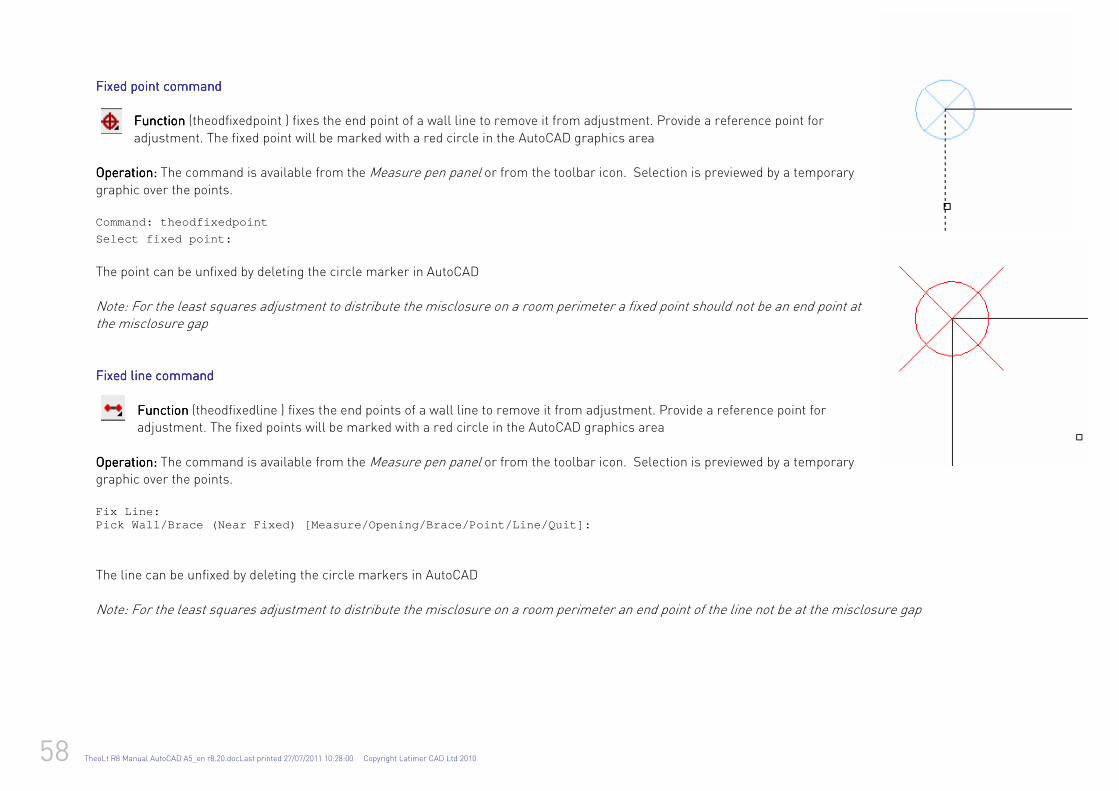
58 TheoLt R8 Manual AutoCAD A5_en r8.20.docLast printed 27/07/2011 10:28:00 Copyright Latimer CAD Ltd 2010
Fixed point commandFixed point commandFixed point commandFixed point command FunctionFunctionFunctionFunction (theodfixedpoint ) fixes the end point of a wall line to remove it from adjustment. Provide a reference point for
adjustment. The fixed point will be marked with a red circle in the AutoCAD graphics area Operation:Operation:Operation:Operation: The command is available from the Measure pen panel or from the toolbar icon. Selection is previewed by a temporary
graphic over the points. Command: theodfixedpoint
Select fixed point:
The point can be unfixed by deleting the circle marker in AutoCAD
Note: For the least squares adjustment to distribute the misclosure on a room perimeter a fixed point should not be an end point at the misclosure gap Fixed Fixed Fixed Fixed linelinelineline command command command command
FunctionFunctionFunctionFunction (theodfixedline ) fixes the end points of a wall line to remove it from adjustment. Provide a reference point for adjustment. The fixed points will be marked with a red circle in the AutoCAD graphics area
OperaOperaOperaOperation:tion:tion:tion: The command is available from the Measure pen panel or from the toolbar icon. Selection is previewed by a temporary graphic over the points.
Fix Line: Pick Wall/Brace (Near Fixed) [Measure/Opening/Brace /Point/Line/Quit]:
The line can be unfixed by deleting the circle markers in AutoCAD
Note: For the least squares adjustment to distribute the misclosure on a room perimeter an end point of the line not be at the misclosure gap
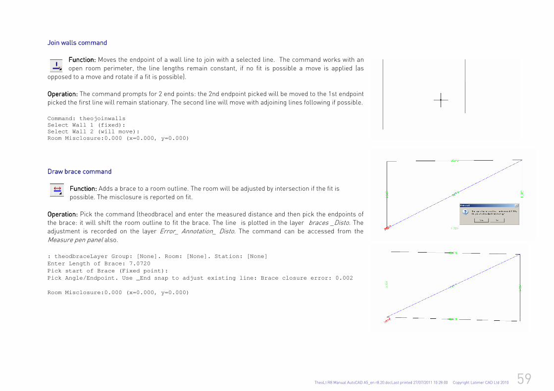
TheoLt R8 Manual AutoCAD A5_en r8.20.docLast printed 27/07/2011 10:28:00 Copyright Latimer CAD Ltd 2010 59
Join walls commandJoin walls commandJoin walls commandJoin walls command
Function:Function:Function:Function: Moves the endpoint of a wall line to join with a selected line. The command works with an
open room perimeter, the line lengths remain constant, if no fit is possible a move is applied (as opposed to a move and rotate if a fit is possible).
Operation:Operation:Operation:Operation: The command prompts for 2 end points: the 2nd endpoint picked will be moved to the 1st endpoint picked the first line will remain stationary. The second line will move with adjoining lines following if possible. Command: theojoinwalls Select Wall 1 (fixed): Select Wall 2 (will move): Room Misclosure:0.000 (x=0.000, y=0.000)
Draw brace commandDraw brace commandDraw brace commandDraw brace command
Function:Function:Function:Function: Adds a brace to a room outline. The room will be adjusted by intersection if the fit is possible. The misclosure is reported on fit.
Operation: Operation: Operation: Operation: Pick the command (theodbrace) and enter the measured distance and then pick the endpoints of the brace: it will shift the room outline to fit the brace. The line is plotted in the layer braces _Disto. The adjustment is recorded on the layer Error_ Annotation_ Disto. The command can be accessed from the
Measure pen panel also. : theodbraceLayer Group: [None]. Room: [None]. Stat ion: [None] Enter Length of Brace: 7.0720 Pick start of Brace (Fixed point): Pick Angle/Endpoint. Use _End snap to adjust existi ng line: Brace closure error: 0.002 Room Misclosure:0.000 (x=0.000, y=0.000)
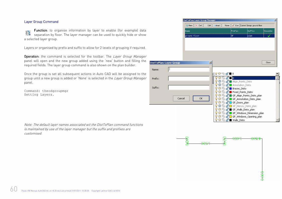
60 TheoLt R8 Manual AutoCAD A5_en r8.20.docLast printed 27/07/2011 10:28:00 Copyright Latimer CAD Ltd 2010
Layer Group CommandLayer Group CommandLayer Group CommandLayer Group Command
FunctionFunctionFunctionFunction: to organise information by layer to enable (for example) data
separation by floor. The layer manager can be used to quickly hide or show a selected layer group.
Layers or organised by prefix and suffix to allow for 2 levels of grouping if required. OperationOperationOperationOperation: the command is selected for the toolbar. The Layer Group Manager panel will open and the new group added using the ‘new’ button and filling the required fields. The layer group command is also shown on the plan builder. Once the group is set all subsequent actions in Auto CAD will be assigned to the group until a new group is added or ‘None’ is selected in the Layer Group Manager panel.
Command: theodgroupmgr Setting Layers. Note: The default layer names associated wit the DistToPlan command functions is maintained by use of the layer manager but the suffix and prefixes are customised.
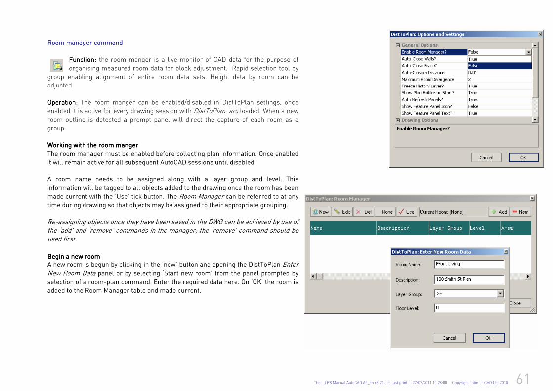
TheoLt R8 Manual AutoCAD A5_en r8.20.docLast printed 27/07/2011 10:28:00 Copyright Latimer CAD Ltd 2010 61
Room manRoom manRoom manRoom manaaaager commandger commandger commandger command
Function: Function: Function: Function: the room manger is a live monitor of CAD data for the purpose of
organising measured room data for block adjustment. Rapid selection tool by group enabling alignment of entire room data sets. Height data by room can be adjusted
Operation: Operation: Operation: Operation: The room manger can be enabled/disabled in DistToPlan settings, once enabled it is active for every drawing session with DistToPlan. arx loaded. When a new
room outline is detected a prompt panel will direct the capture of each room as a group. Working with the room mangerWorking with the room mangerWorking with the room mangerWorking with the room manger
The room manager must be enabled before collecting plan information. Once enabled
it will remain active for all subsequent AutoCAD sessions until disabled.
A room name needs to be assigned along with a layer group and level. This
information will be tagged to all objects added to the drawing once the room has been
made current with the ‘Use’ tick button. The Room Manager can be referred to at any time during drawing so that objects may be assigned to their appropriate grouping.
Re-assigning objects once they have been saved in the DWG can be achieved by use of the ‘add’ and ‘remove’ commands in the manager; the ‘remove’ command should be used first.
Begin a new roomBegin a new roomBegin a new roomBegin a new room
A new room is begun by clicking in the ‘new’ button and opening the DistToPlan Enter New Room Data panel or by selecting ‘Start new room’ from the panel prompted by
selection of a room-plan command. Enter the required data here. On ‘OK’ the room is
added to the Room Manager table and made current.
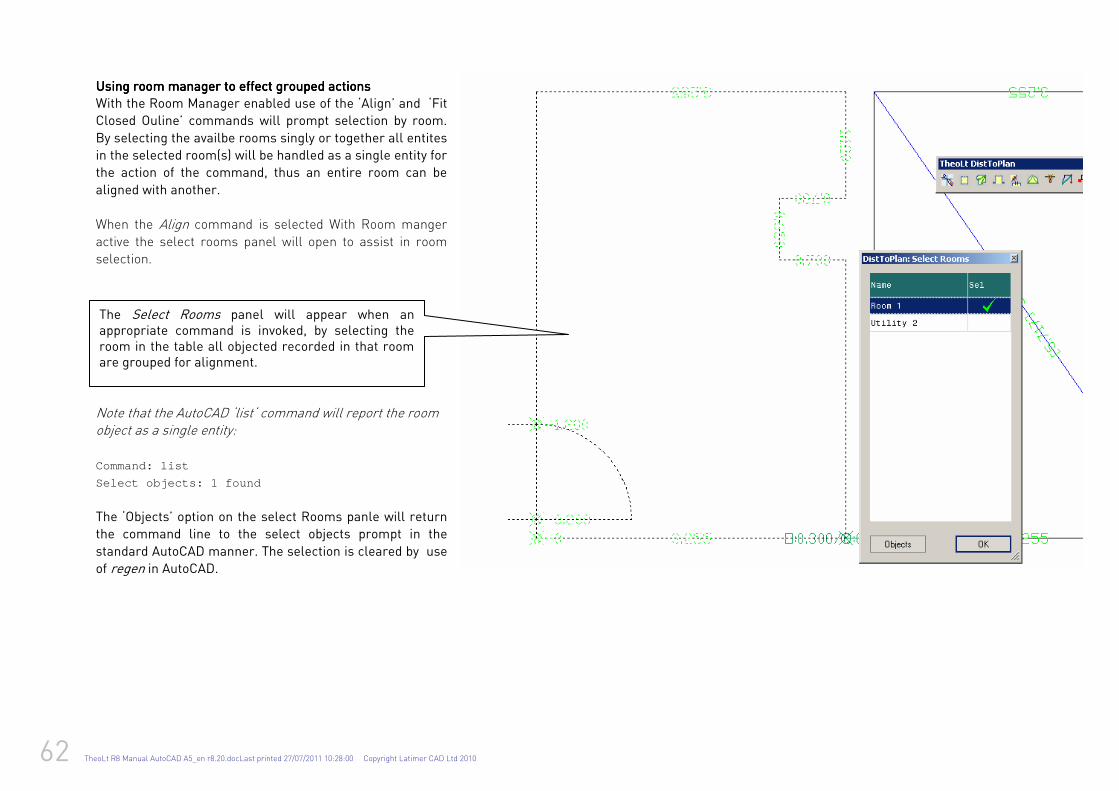
62 TheoLt R8 Manual AutoCAD A5_en r8.20.docLast printed 27/07/2011 10:28:00 Copyright Latimer CAD Ltd 2010
Using room manager to effect grouped actionsUsing room manager to effect grouped actionsUsing room manager to effect grouped actionsUsing room manager to effect grouped actions
With the Room Manager enabled use of the ‘Align’ and ‘Fit
Closed Ouline’ commands will prompt selection by room.
By selecting the availbe rooms singly or together all entites
in the selected room(s) will be handled as a single entity for
the action of the command, thus an entire room can be
aligned with another.
When the Align command is selected With Room manger
active the select rooms panel will open to assist in room selection.
Note that the AutoCAD ‘list‘ command will report the room object as a single entity: Command: list
Select objects: 1 found
The ‘Objects’ option on the select Rooms panle will return
the command line to the select objects prompt in the
standard AutoCAD manner. The selection is cleared by use
of regen in AutoCAD.
The Select Rooms panel will appear when an appropriate command is invoked, by selecting the room in the table all objected recorded in that room are grouped for alignment.
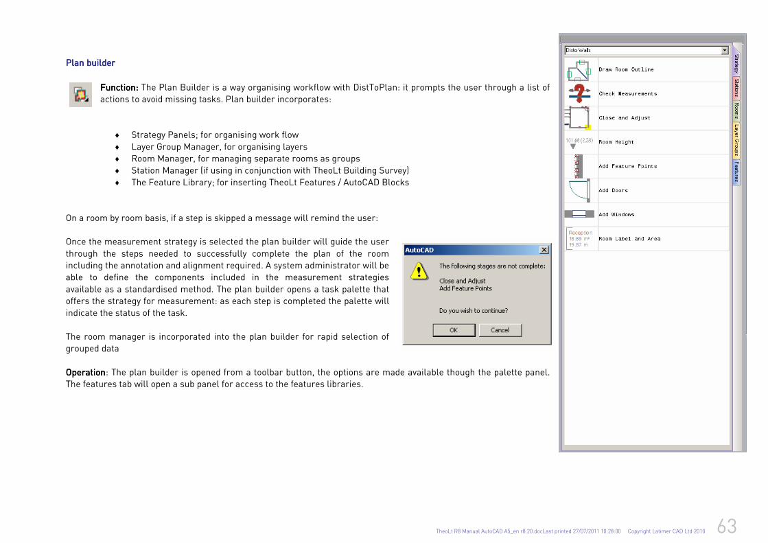
TheoLt R8 Manual AutoCAD A5_en r8.20.docLast printed 27/07/2011 10:28:00 Copyright Latimer CAD Ltd 2010 63
Plan builderPlan builderPlan builderPlan builder
FunctionFunctionFunctionFunction:::: The Plan Builder is a way organising workflow with DistToPlan: it prompts the user through a list of
actions to avoid missing tasks. Plan builder incorporates:
♦ Strategy Panels; for organising work flow
♦ Layer Group Manager, for organising layers
♦ Room Manager, for managing separate rooms as groups
♦ Station Manager (if using in conjunction with TheoLt Building Survey)
♦ The Feature Library; for inserting TheoLt Features / AutoCAD Blocks
On a room by room basis, if a step is skipped a message will remind the user: Once the measurement strategy is selected the plan builder will guide the user
through the steps needed to successfully complete the plan of the room
including the annotation and alignment required. A system administrator will be
able to define the components included in the measurement strategies
available as a standardised method. The plan builder opens a task palette that
offers the strategy for measurement: as each step is completed the palette will
indicate the status of the task.
The room manager is incorporated into the plan builder for rapid selection of
grouped data
OperationOperationOperationOperation: The plan builder is opened from a toolbar button, the options are made available though the palette panel.
The features tab will open a sub panel for access to the features libraries.
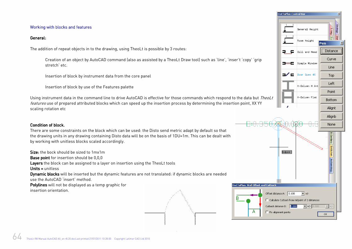
64 TheoLt R8 Manual AutoCAD A5_en r8.20.docLast printed 27/07/2011 10:28:00 Copyright Latimer CAD Ltd 2010
Working with blocks and featuresWorking with blocks and featuresWorking with blocks and featuresWorking with blocks and features
General:General:General:General:
The addition of repeat objects in to the drawing, using TheoLt is possible by 3 routes:
Creation of an object by AutoCAD command (also as assisted by a TheoLt Draw tool) such as ‘line’, ‘inser’t ‘copy’ ‘grip
stretch’ etc.
Insertion of block by instrument data from the core panel
Insertion of block by use of the Features palette
Using instrument data in the command line to drive AutoCAD is effective for those commands which respond to the data but TheoLt features use of prepared attributed blocks which can speed up the insertion process by determining the insertion point, XX YY
scaling rotation etc
Condition of block.Condition of block.Condition of block.Condition of block.
There are some constraints on the block which can be used: the Disto send metric adapt by default so that
the drawing units in any drawing containing Disto data will be on the basis of 1DU=1m. This can be dealt with
by working with unitless blocks scaled accordingly.
Size: Size: Size: Size: the bock should be sized to 1mx1m
Base Base Base Base point point point point for insertion should be 0,0,0
Layers Layers Layers Layers the block can be assigned to a layer on insertion using the TheoLt tools
Units = Units = Units = Units = unitless
Dynamic blocksDynamic blocksDynamic blocksDynamic blocks will be inserted but the dynamic features are not translated: if dynamic blocks are needed
use the AutoCAD ‘insert’ method.
PolylinesPolylinesPolylinesPolylines will not be displayed as a temp graphic for
insertion orientation.
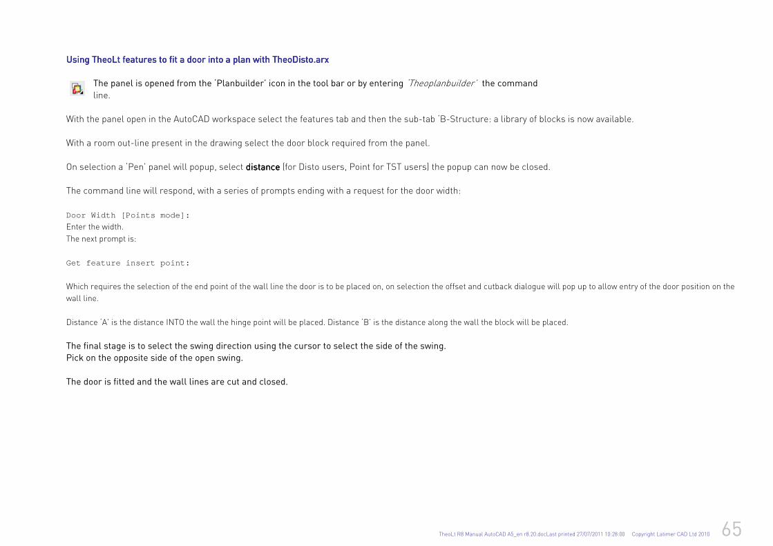
TheoLt R8 Manual AutoCAD A5_en r8.20.docLast printed 27/07/2011 10:28:00 Copyright Latimer CAD Ltd 2010 65
Using TheoLt features to fit a door into a plan with TheoDisto.arxUsing TheoLt features to fit a door into a plan with TheoDisto.arxUsing TheoLt features to fit a door into a plan with TheoDisto.arxUsing TheoLt features to fit a door into a plan with TheoDisto.arx
The panel is opened from the ‘Planbuilder’ icon in the tool bar or by entering ‘Theoplanbuilder’ the command
line. With the panel open in the AutoCAD workspace select the features tab and then the sub-tab ‘B-Structure: a library of blocks is now available.
With a room out-line present in the drawing select the door block required from the panel.
On selection a ‘Pen’ panel will popup, select distancedistancedistancedistance (for Disto users, Point for TST users) the popup can now be closed. The command line will respond, with a series of prompts ending with a request for the door width:
Door Width [Points mode]:
Enter the width.
The next prompt is:
Get feature insert point:
Which requires the selection of the end point of the wall line the door is to be placed on, on selection the offset and cutback dialogue will pop up to allow entry of the door position on the
wall line.
Distance ‘A’ is the distance INTO the wall the hinge point will be placed. Distance ‘B’ is the distance along the wall the block will be placed.
The final stage is to select the swing direction using the cursor to select the side of the swing.
Pick on the opposite side of the open swing.
The door is fitted and the wall lines are cut and closed.
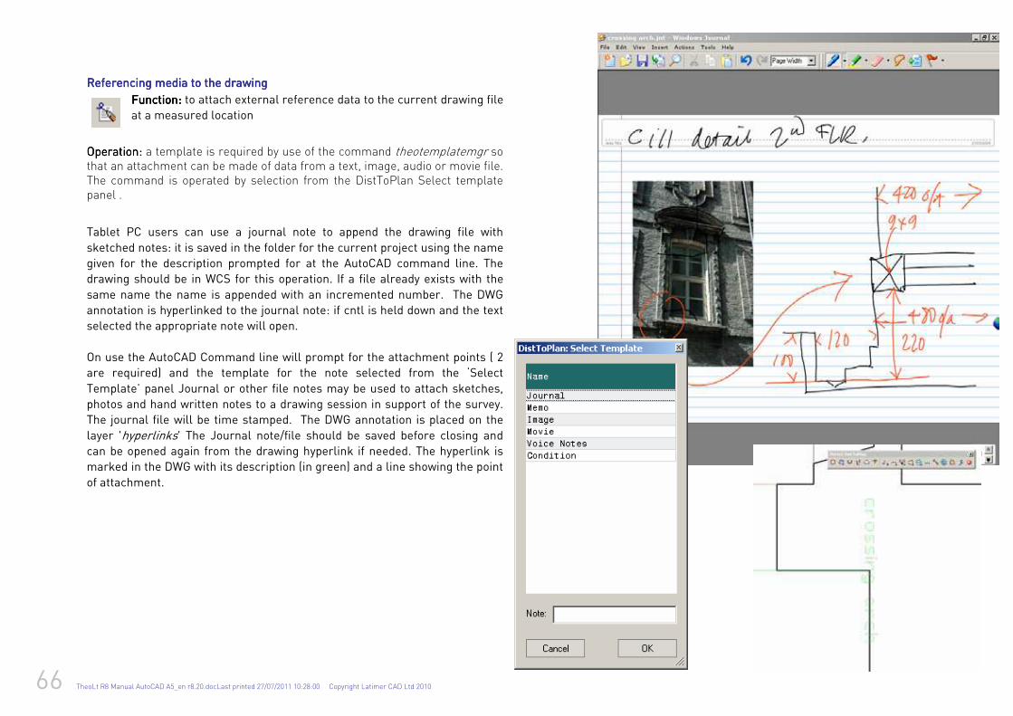
66 TheoLt R8 Manual AutoCAD A5_en r8.20.docLast printed 27/07/2011 10:28:00 Copyright Latimer CAD Ltd 2010
RRRReferencing media toeferencing media toeferencing media toeferencing media to the drawingthe drawingthe drawingthe drawing
FunctionFunctionFunctionFunction: : : : to attach external reference data to the current drawing file
at a measured location
OpeOpeOpeOperation: ration: ration: ration: a template is required by use of the command theotemplatemgr so that an attachment can be made of data from a text, image, audio or movie file. The command is operated by selection from the DistToPlan Select template panel .
Tablet PC users can use a journal note to append the drawing file with
sketched notes: it is saved in the folder for the current project using the name
given for the description prompted for at the AutoCAD command line. The
drawing should be in WCS for this operation. If a file already exists with the
same name the name is appended with an incremented number. The DWG
annotation is hyperlinked to the journal note: if cntl is held down and the text
selected the appropriate note will open.
On use the AutoCAD Command line will prompt for the attachment points ( 2
are required) and the template for the note selected from the ‘Select
Template’ panel Journal or other file notes may be used to attach sketches,
photos and hand written notes to a drawing session in support of the survey.
The journal file will be time stamped. The DWG annotation is placed on the
layer 'hyperlinks' The Journal note/file should be saved before closing and can be opened again from the drawing hyperlink if needed. The hyperlink is
marked in the DWG with its description (in green) and a line showing the point
of attachment.
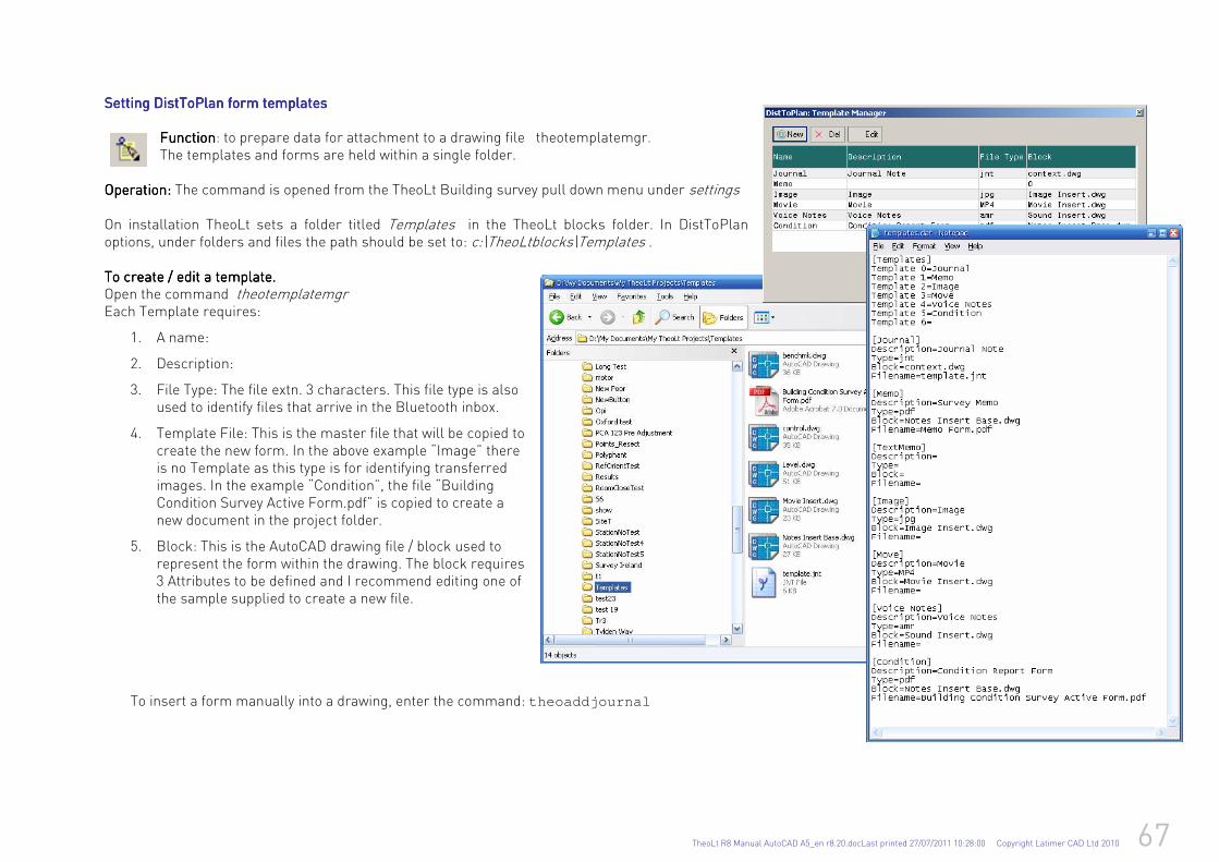
TheoLt R8 Manual AutoCAD A5_en r8.20.docLast printed 27/07/2011 10:28:00 Copyright Latimer CAD Ltd 2010 67
Setting DistToPlan form templatesSetting DistToPlan form templatesSetting DistToPlan form templatesSetting DistToPlan form templates
FunctionFunctionFunctionFunction: to prepare data for attachment to a drawing file theotemplatemgr. The templates and forms are held within a single folder.
OperatOperatOperatOperation: ion: ion: ion: The command is opened from the TheoLt Building survey pull down menu under settings On installation TheoLt sets a folder titled Templates in the TheoLt blocks folder. In DistToPlan options, under folders and files the path should be set to: c:\TheoLtblocks\Templates . To create / edit a template. To create / edit a template. To create / edit a template. To create / edit a template. Open the command theotemplatemgr Each Template requires:
1. A name:
2. Description:
3. File Type: The file extn. 3 characters. This file type is also used to identify files that arrive in the Bluetooth inbox.
4. Template File: This is the master file that will be copied to create the new form. In the above example “Image” there is no Template as this type is for identifying transferred images. In the example “Condition”, the file “Building Condition Survey Active Form.pdf” is copied to create a new document in the project folder.
5. Block: This is the AutoCAD drawing file / block used to represent the form within the drawing. The block requires 3 Attributes to be defined and I recommend editing one of the sample supplied to create a new file.
To insert a form manually into a drawing, enter the command: theoaddjournal
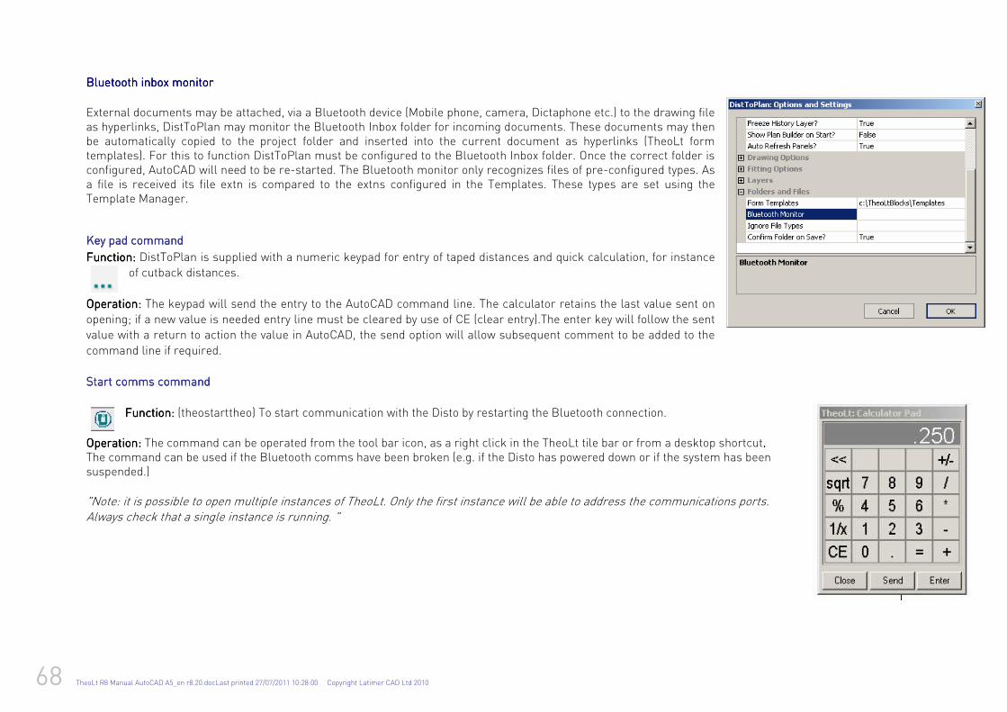
68 TheoLt R8 Manual AutoCAD A5_en r8.20.docLast printed 27/07/2011 10:28:00 Copyright Latimer CAD Ltd 2010
Bluetooth inbox monitor Bluetooth inbox monitor Bluetooth inbox monitor Bluetooth inbox monitor
External documents may be attached, via a Bluetooth device (Mobile phone, camera, Dictaphone etc.) to the drawing file as hyperlinks, DistToPlan may monitor the Bluetooth Inbox folder for incoming documents. These documents may then be automatically copied to the project folder and inserted into the current document as hyperlinks (TheoLt form templates). For this to function DistToPlan must be configured to the Bluetooth Inbox folder. Once the correct folder is configured, AutoCAD will need to be re-started. The Bluetooth monitor only recognizes files of pre-configured types. As a file is received its file extn is compared to the extns configured in the Templates. These types are set using the Template Manager.
Key pad commandKey pad commandKey pad commandKey pad command
Function:Function:Function:Function: DistToPlan is supplied with a numeric keypad for entry of taped distances and quick calculation, for instance of cutback distances.
OperatioOperatioOperatioOperation:n:n:n: The keypad will send the entry to the AutoCAD command line. The calculator retains the last value sent on opening; if a new value is needed entry line must be cleared by use of CE (clear entry).The enter key will follow the sent value with a return to action the value in AutoCAD, the send option will allow subsequent comment to be added to the
command line if required. Start comms commandStart comms commandStart comms commandStart comms command
Function: Function: Function: Function: (theostarttheo) To start communication with the Disto by restarting the Bluetooth connection.
OperatioOperatioOperatioOperation: n: n: n: The command can be operated from the tool bar icon, as a right click in the TheoLt tile bar or from a desktop shortcut. . . . The command can be used if the Bluetooth comms have been broken (e.g. if the Disto has powered down or if the system has been suspended.) "Note: it is possible to open multiple instances of TheoLt. Only the first instance will be able to address the communications ports. Always check that a single instance is running. "
TheoLt R8 Manual AutoCAD A5_en r8.20.docLast printed 27/07/2011 10:28:00 Copyright Latimer CAD Ltd 2010 69
Cancel commandCancel commandCancel commandCancel command
Function:Function:Function:Function: to stop DistToPlan commands and reset the AutoCAD command line for the next command.
Operation:Operation:Operation:Operation: (theocancel) the command is operated form the tool bar button. Additionally the command will clear ‘grips’ selection in both AutoCAD and Bricscad
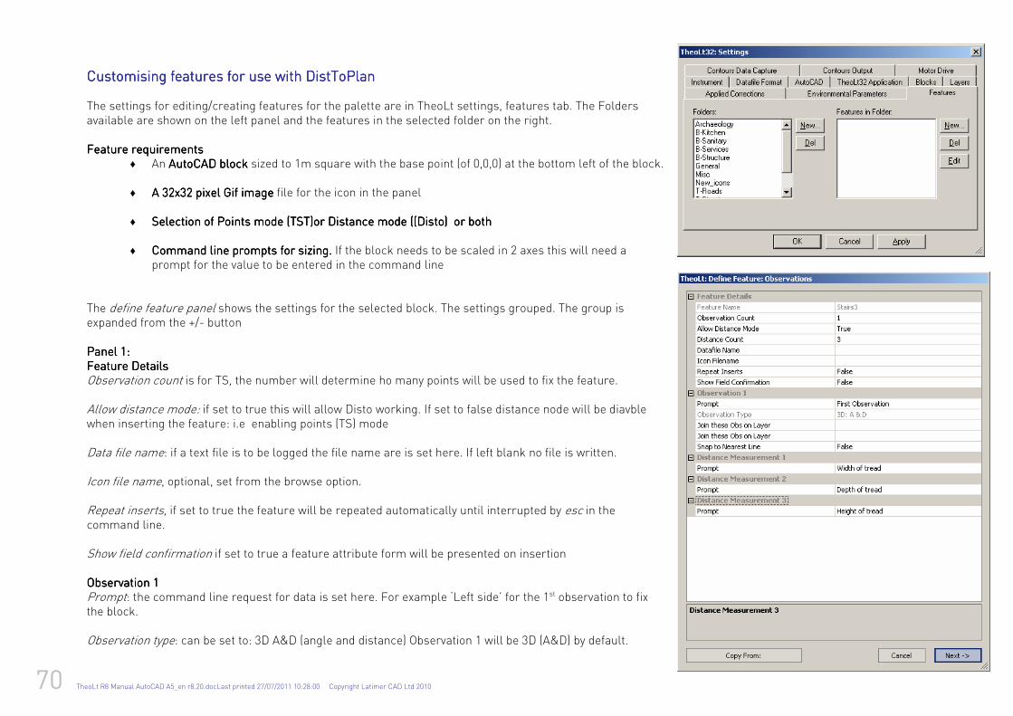
70 TheoLt R8 Manual AutoCAD A5_en r8.20.docLast printed 27/07/2011 10:28:00 Copyright Latimer CAD Ltd 2010
CustomiCustomiCustomiCustomising features for use with DistToPlan sing features for use with DistToPlan sing features for use with DistToPlan sing features for use with DistToPlan The settings for editing/creating features for the palette are in TheoLt settings, features tab. The Folders available are shown on the left panel and the features in the selected folder on the right. Feature requirFeature requirFeature requirFeature requirementsementsementsements
♦ An AutoCAD blockAutoCAD blockAutoCAD blockAutoCAD block sized to 1m square with the base point (of 0,0,0) at the bottom left of the block.
♦ A 32x32 pixel Gif imageA 32x32 pixel Gif imageA 32x32 pixel Gif imageA 32x32 pixel Gif image file for the icon in the panel
♦ Selection of Points mode (TST)or Distance mode ((Disto) or bothSelection of Points mode (TST)or Distance mode ((Disto) or bothSelection of Points mode (TST)or Distance mode ((Disto) or bothSelection of Points mode (TST)or Distance mode ((Disto) or both
♦ Command line prompts for Command line prompts for Command line prompts for Command line prompts for sizingsizingsizingsizing. . . . If the block needs to be scaled in 2 axes this will need a prompt for the value to be entered in the command line
The define feature panel shows the settings for the selected block. The settings grouped. The group is expanded from the +/- button Panel 1:Panel 1:Panel 1:Panel 1: Feature DetailsFeature DetailsFeature DetailsFeature Details Observation count is for TS, the number will determine ho many points will be used to fix the feature. Allow distance mode: if set to true this will allow Disto working. If set to false distance node will be diavble when inserting the feature: i.e enabling points (TS) mode Data file name: if a text file is to be logged the file name are is set here. If left blank no file is written. Icon file name, optional, set from the browse option. Repeat inserts, if set to true the feature will be repeated automatically until interrupted by esc in the command line. Show field confirmation if set to true a feature attribute form will be presented on insertion ObservationObservationObservationObservation 1 1 1 1 Prompt: the command line request for data is set here. For example ‘Left side’ for the 1st observation to fix the block. Observation type: can be set to: 3D A&D (angle and distance) Observation 1 will be 3D (A&D) by default.
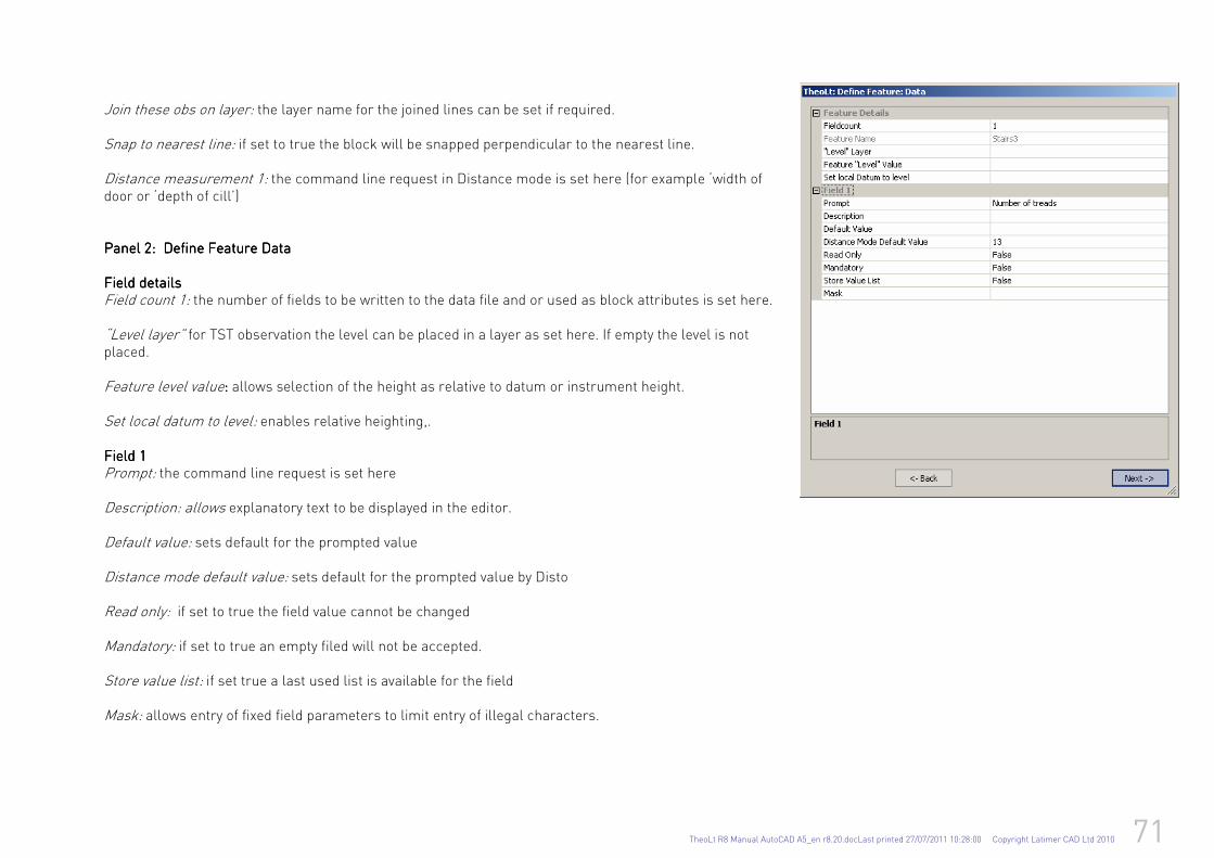
TheoLt R8 Manual AutoCAD A5_en r8.20.docLast printed 27/07/2011 10:28:00 Copyright Latimer CAD Ltd 2010 71
Join these obs on layer: the layer name for the joined lines can be set if required. Snap to nearest line: if set to true the block will be snapped perpendicular to the nearest line. Distance measurement 1: the command line request in Distance mode is set here (for example ‘width of door or ‘depth of cill’) Panel 2: Panel 2: Panel 2: Panel 2: Define Define Define Define Feature DFeature DFeature DFeature Dataataataata FFFField detailsield detailsield detailsield details Field count 1: the number of fields to be written to the data file and or used as block attributes is set here. “Level layer” for TST observation the level can be placed in a layer as set here. If empty the level is not placed. Feature level value: : : : allows selection of the height as relative to datum or instrument height. Set local datum to level: enables relative heighting,. Field 1Field 1Field 1Field 1 Prompt: the command line request is set here Description: allows explanatory text to be displayed in the editor. Default value: sets default for the prompted value Distance mode default value: sets default for the prompted value by Disto Read only: if set to true the field value cannot be changed Mandatory: if set to true an empty filed will not be accepted. Store value list: if set true a last used list is available for the field Mask: allows entry of fixed field parameters to limit entry of illegal characters.
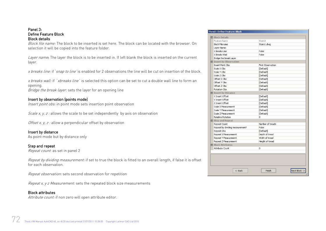
72 TheoLt R8 Manual AutoCAD A5_en r8.20.docLast printed 27/07/2011 10:28:00 Copyright Latimer CAD Ltd 2010
Panel 3: Panel 3: Panel 3: Panel 3: Define Define Define Define Feature Feature Feature Feature BlockBlockBlockBlock Block details Block details Block details Block details Block file name: The block to be inserted is set here. The block can be located with the browser. On selection it will be copied into the feature folder. Layer name: : : : The layer the block is to be inserted in. If left blank the block is inserted on the current layer. x breaks line: if ‘snap to line’ is enabled for 2 observations the line will be cut on insertion of the block. x breaks wall: if ‘xbreaks line’ is selected this option can be set to cut a double wall line to form an opening. Bridge the break layer: sets the layer for an opening line Insert by observationInsert by observationInsert by observationInsert by observation (points mode) (points mode) (points mode) (points mode) Insert point obs: in point mode sets insertion point observation Scale x, y, z : allows the scale to be set independently by axis on observation Offset x, y, z : allow a perpendicular offset by observation InseInseInseInsert by distancert by distancert by distancert by distance As point mode but by distance only Step and repeatStep and repeatStep and repeatStep and repeat Repeat count: as set in panel 2 Repeat by dividing measurement: if set to true the block is fitted to an overall length, if false it is offset for each observation. Repeat observation: sets second observation for repetition Repeat x, y z Measurement: sets the repeated block size measurements Block attributesBlock attributesBlock attributesBlock attributes Attribute count: if non zero will open attribute editor.
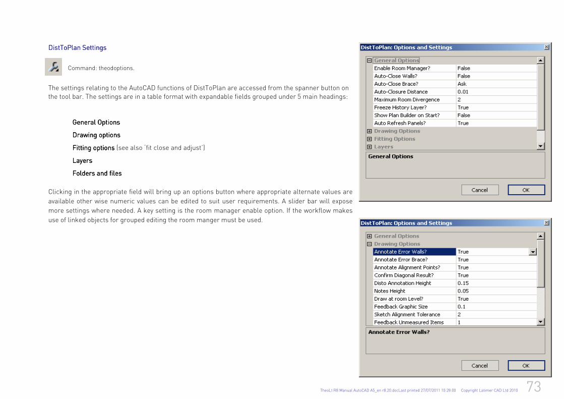
TheoLt R8 Manual AutoCAD A5_en r8.20.docLast printed 27/07/2011 10:28:00 Copyright Latimer CAD Ltd 2010 73
DDDDistToPlan Settings istToPlan Settings istToPlan Settings istToPlan Settings
Command: theodoptions.
The settings relating to the AutoCAD functions of DistToPlan are accessed from the spanner button on the tool bar. The settings are in a table format with expandable fields grouped under 5 main headings:
General OptionsGeneral OptionsGeneral OptionsGeneral Options
Drawing options Drawing options Drawing options Drawing options
Fitting options Fitting options Fitting options Fitting options (see also ‘fit close and adjust’)
LayersLayersLayersLayers
Folders and filesFolders and filesFolders and filesFolders and files
Clicking in the appropriate field will bring up an options button where appropriate alternate values are
available other wise numeric values can be edited to suit user requirements. A slider bar will expose
more settings where needed. A key setting is the room manager enable option. If the workflow makes
use of linked objects for grouped editing the room manger must be used.
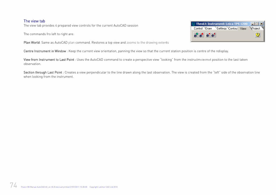
74 TheoLt R8 Manual AutoCAD A5_en r8.20.docLast printed 27/07/2011 10:28:00 Copyright Latimer CAD Ltd 2010
The The The The viewviewviewview tab tab tab tab The view tab provides 4 prepared view controls for the current AutoCAD session
The commands fro left to right are: Plan Plan Plan Plan WorldWorldWorldWorld: Same as AutoCAD plan command. Restores a top view and zooms to the drawing extents
Centre Instrument in WindowCentre Instrument in WindowCentre Instrument in WindowCentre Instrument in Window : Keep the current view orientation, panning the view so that the current station position is centre of the ndisplay.
VieVieVieView from Instrument to Last Pointw from Instrument to Last Pointw from Instrument to Last Pointw from Instrument to Last Point : Uses the AutoCAD command to create a perspective view “looking” from the instrudmvieenwt position to the last taken observation.
Section through Last PointSection through Last PointSection through Last PointSection through Last Point : Creates a view perpendicular to the line drawn along the last observation. The view is created from the “left” side of the observation line when looking from the instrument.

TheoLt R8 Manual AutoCAD A5_en r8.20.docLast printed 27/07/2011 10:28:00 Copyright Latimer CAD Ltd 2010 75
3D views in AutoCAD3D views in AutoCAD3D views in AutoCAD3D views in AutoCAD for façade survey for façade survey for façade survey for façade survey TheoLt sends 3D data to AutoCAD which is plotted in the lines and layers of your choice. It is useful to be able to vew the drawing as a façade. One method to achieve this is to use AutoCAD’s UCS (User Co-ordinate System) command to set up a façade UCS and view it square on:
1. Place a polyline across the plan by snapping to the ends of a measured line (because this will guarantee the UCS will be true level)
2. Use the UCS command ‘e’ ( for entity) option to fix a UCS to the poly line: pick the poly line when prompted.
3. Use ‘Plan’ to get a plan view of the new UCS
4. Rotate the UCS about the required axis by 90 deg to point Z at the viewer of the façade. Watch the UCS icon to see what happening.( this is the default vaule in
AutoCAD to its accepted by ‘enter’: the command is ‘UCS’ , X , 90, enter
5. Use’ plan’ to get a plan view of the new UCS
6. Use UCSICON command to set ‘Noorigin’ to get the icon out of the way. Save the UCS (‘S’ option at UCS command) for future use.
7. Enjoy your facade view!
TheoLt will plot lines true to the instrument orientation in AutoCAD regardless of the UCS and view ports in model space can be used to run plan and elevation drawings at the same time. The façade UCS is useful when preparing views of the data for elevation drawings.
Using the AutoCAD ‘View’ command to save views is advised as a short cut to saved elevation views. Once the façade view is as desired it can be named for future use.
From Left to right: 1:the plan view in WCS (World Co-ordinate System), 2:the new UCS fitted to the polyline, 3Plan view of the 1st UCS.4: :the X axis rotation of the UCS and 5: ‘plan’ view of the façade UCS.
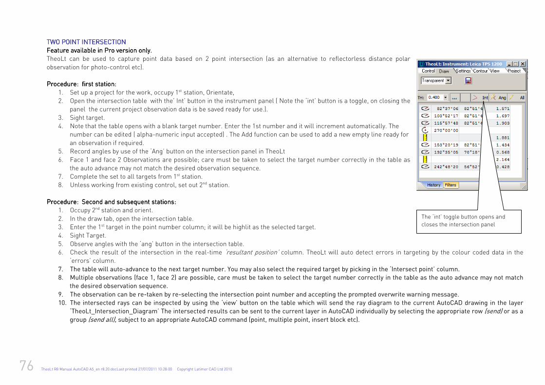
76 TheoLt R8 Manual AutoCAD A5_en r8.20.docLast printed 27/07/2011 10:28:00 Copyright Latimer CAD Ltd 2010
TWOTWOTWOTWO POINT INTERSECTION POINT INTERSECTION POINT INTERSECTION POINT INTERSECTION Feature available in Feature available in Feature available in Feature available in Pro version only.Pro version only.Pro version only.Pro version only. TheoLt can be used to capture point data based on 2 point intersection (as an alternative to reflectorless distance polar
observation for photo-control etc). Procedure: first station:Procedure: first station:Procedure: first station:Procedure: first station:
1. Set up a project for the work, occupy 1st station, Orientate, 2. Open the intersection table with the’ Int’ button in the instrument panel ( Note the ‘int’ button is a toggle, on closing the
panel the current project observation data is be saved ready for use.).
3. Sight target. 4. Note that the table opens with a blank target number. Enter the 1st number and it will increment automatically. The
number can be edited ( alpha-numeric input accepted) . The Add function can be used to add a new empty line ready for
an observation if required. 5. Record angles by use of the ‘Ang’ button on the intersection panel in TheoLt 6. Face 1 and face 2 Observations are possible; care must be taken to select the target number correctly in the table as
the auto advance may not match the desired observation sequence. 7. Complete the set to all targets from 1st station. 8. Unless working from existing control, set out 2nd station.
ProcProcProcProcedure: Second and subsequent stations:edure: Second and subsequent stations:edure: Second and subsequent stations:edure: Second and subsequent stations:
1. Occupy 2nd station and orient.
2. In the draw tab, open the intersection table. 3. Enter the 1st target in the point number column; it will be highlit as the selected target. 4. Sight Target.
5. Observe angles with the ‘ang’ button in the intersection table. 6. Check the result of the intersection in the real-time ‘resultant position’ column. TheoLt will auto detect errors in targeting by the colour coded data in the
‘errors’ column.
7. The table will auto-advance to the next target number. You may also select the required target by picking in the ‘Intersect point’ column.
8. Multiple observations (face 1, face 2) are possible, care must be taken to select the target number correctly in the table as the auto advance may not match
the desired observation sequence.
9. The observation can be re-taken by re-selecting the intersection point number and accepting the prompted overwrite warning message.
10. The intersected rays can be inspected by using the ‘view’ button on the table which will send the ray diagram to the current AutoCAD drawing in the layer
‘TheoLt_Intersection_Diagram’ The intersected results can be sent to the current layer in AutoCAD individually by selecting the appropriate row (send) or as a group (send all), subject to an appropriate AutoCAD command (point, multiple point, insert block etc).
The ‘int’ toggle button opens and
closes the intersection panel
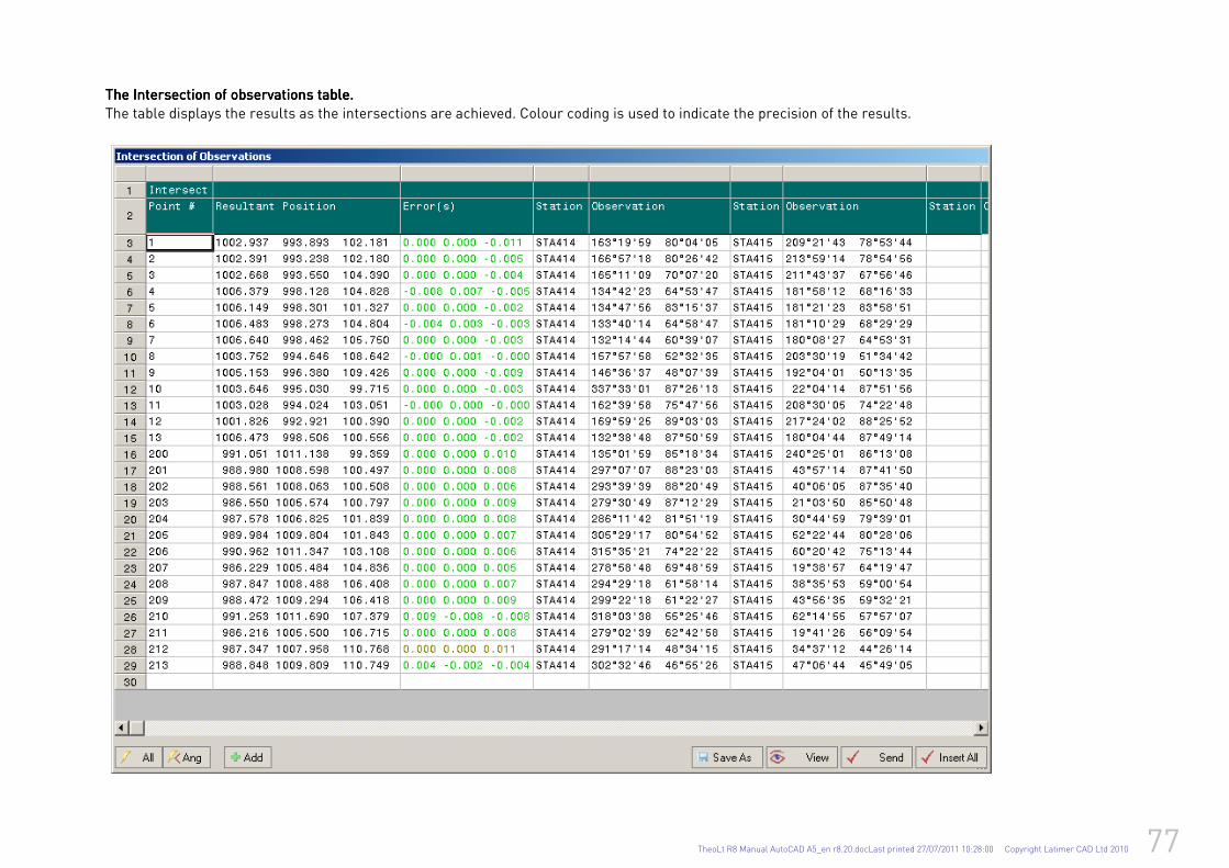
TheoLt R8 Manual AutoCAD A5_en r8.20.docLast printed 27/07/2011 10:28:00 Copyright Latimer CAD Ltd 2010 77
The Intersection of observations table. The Intersection of observations table. The Intersection of observations table. The Intersection of observations table.
The table displays the results as the intersections are achieved. Colour coding is used to indicate the precision of the results.
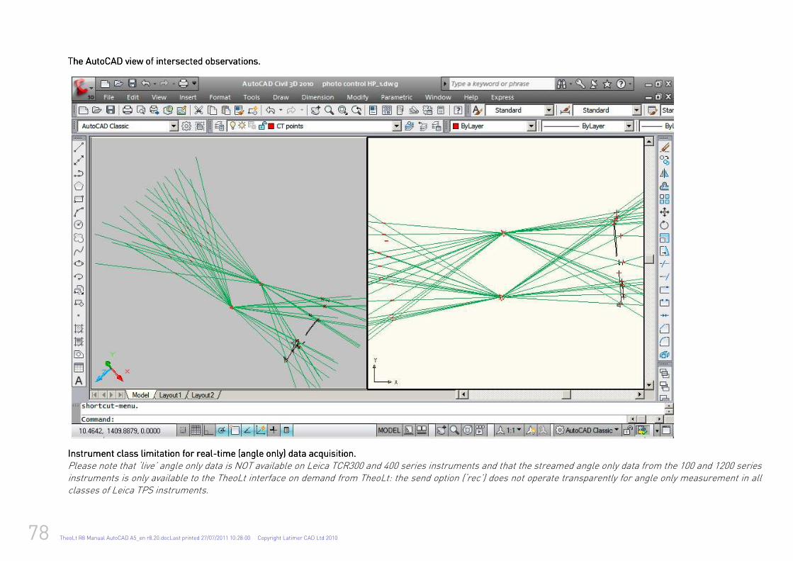
78 TheoLt R8 Manual AutoCAD A5_en r8.20.docLast printed 27/07/2011 10:28:00 Copyright Latimer CAD Ltd 2010
The AutoCAD view of intersected observations.The AutoCAD view of intersected observations.The AutoCAD view of intersected observations.The AutoCAD view of intersected observations.
Instrument class limitation foInstrument class limitation foInstrument class limitation foInstrument class limitation for realr realr realr real----time (angle only) data acquisition.time (angle only) data acquisition.time (angle only) data acquisition.time (angle only) data acquisition.
Please note that ‘live’ angle only data is NOT available on Leica TCR300 and 400 series instruments and that the streamed angle only data from the 100 and 1200 series instruments is only available to the TheoLt interface on demand from TheoLt: the send option (‘rec’) does not operate transparently for angle only measurement in all classes of Leica TPS instruments.
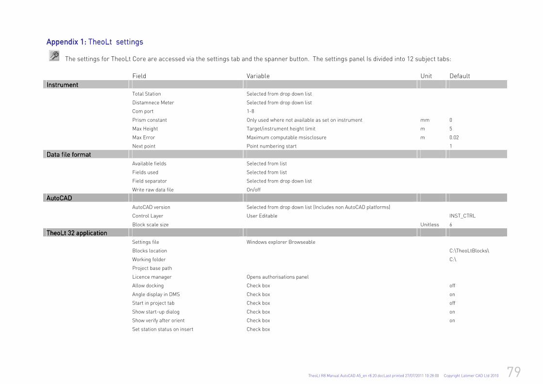
TheoLt R8 Manual AutoCAD A5_en r8.20.docLast printed 27/07/2011 10:28:00 Copyright Latimer CAD Ltd 2010 79
Appendix 1: Appendix 1: Appendix 1: Appendix 1: TheTheTheTheoLt oLt oLt oLt settings settings settings settings The settings for TheoLt Core are accessed via the settings tab and the spanner button. The settings panel Is divided into 12 subject tabs:
Field Variable Unit Default
InstrumentInstrumentInstrumentInstrument
Total Station Selected from drop down list
Distamnece Meter Selected from drop down list
Com port 1-8
Prism constant Only used where not available as set on instrument mm 0
Max Height Target/instrument height limit m 5
Max Error Maximum computable msisclosure m 0.02
Next point Point numbering start 1
Data file formatData file formatData file formatData file format
Available fields Selected from list
Fields used Selected from list
Field separator Selected from drop down list
Write raw data file On/off
AutoCADAutoCADAutoCADAutoCAD
AutoCAD version Selected from drop down list (Includes non AutoCAD platforms)
Control Layer User Editable INST_CTRL
Block scale size Unitless 6
TheoLt 32 applicationTheoLt 32 applicationTheoLt 32 applicationTheoLt 32 application
Settings file Windows explorer Browseable
Blocks location C:\TheoLtBlocks\
Working folder C:\
Project base path
Licence manager Opens authorisations panel
Allow docking Check box off
Angle display in DMS Check box on
Start in project tab Check box off
Show start-up dialog Check box on
Show verify after orient Check box on
Set station status on insert Check box
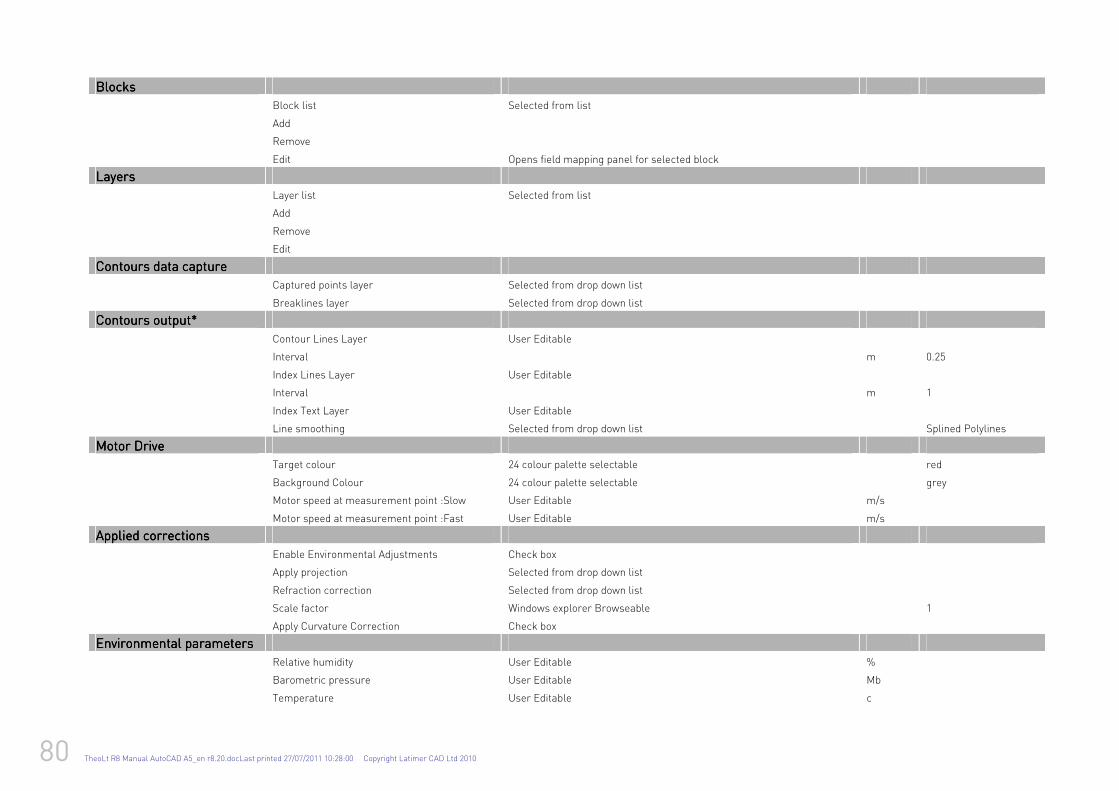
80 TheoLt R8 Manual AutoCAD A5_en r8.20.docLast printed 27/07/2011 10:28:00 Copyright Latimer CAD Ltd 2010
BlocksBlocksBlocksBlocks
Block list Selected from list
Add
Remove
Edit Opens field mapping panel for selected block
LayersLayersLayersLayers
Layer list Selected from list
Add
Remove
Edit
Contours data captureContours data captureContours data captureContours data capture
Captured points layer Selected from drop down list
Breaklines layer Selected from drop down list
Contours output*Contours output*Contours output*Contours output*
Contour Lines Layer User Editable
Interval m 0.25
Index Lines Layer User Editable
Interval m 1
Index Text Layer User Editable
Line smoothing Selected from drop down list Splined Polylines
Motor DriMotor DriMotor DriMotor Driveveveve
Target colour 24 colour palette selectable red
Background Colour 24 colour palette selectable grey
Motor speed at measurement point :Slow User Editable m/s
Motor speed at measurement point :Fast User Editable m/s
Applied correctionsApplied correctionsApplied correctionsApplied corrections
Enable Environmental Adjustments Check box
Apply projection Selected from drop down list
Refraction correction Selected from drop down list
Scale factor Windows explorer Browseable 1
Apply Curvature Correction Check box
Environmental Environmental Environmental Environmental parametersparametersparametersparameters
Relative humidity User Editable %
Barometric pressure User Editable Mb
Temperature User Editable c
TheoLt R8 Manual AutoCAD A5_en r8.20.docLast printed 27/07/2011 10:28:00 Copyright Latimer CAD Ltd 2010 81
Height above nean sea level User Editable m
FeaturesFeaturesFeaturesFeatures
Folders Selected from list
Features in Folder Selected from list
New Opens define feature panel
Del Deletes selected field
Edit Opens define feature panel for selected block
* Further settings are included in TheoContour arx controls
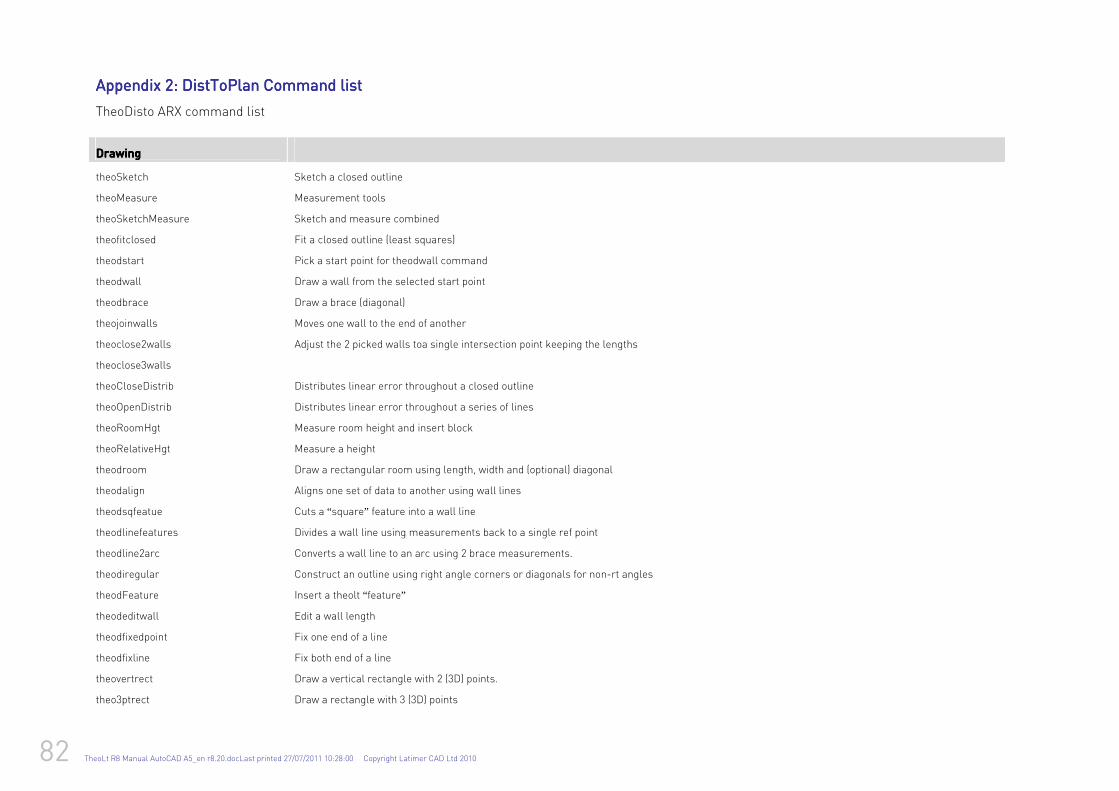
82 TheoLt R8 Manual AutoCAD A5_en r8.20.docLast printed 27/07/2011 10:28:00 Copyright Latimer CAD Ltd 2010
Appendix Appendix Appendix Appendix 2222: DistToPlan Command li: DistToPlan Command li: DistToPlan Command li: DistToPlan Command listststst
TheoDisto ARX command list
Drawing Drawing Drawing Drawing
theoSketch Sketch a closed outline
theoMeasure Measurement tools
theoSketchMeasure Sketch and measure combined
theofitclosed Fit a closed outline (least squares)
theodstart Pick a start point for theodwall command
theodwall Draw a wall from the selected start point
theodbrace Draw a brace (diagonal)
theojoinwalls Moves one wall to the end of another
theoclose2walls Adjust the 2 picked walls toa single intersection point keeping the lengths
theoclose3walls
theoCloseDistrib Distributes linear error throughout a closed outline
theoOpenDistrib Distributes linear error throughout a series of lines
theoRoomHgt Measure room height and insert block
theoRelativeHgt Measure a height
theodroom Draw a rectangular room using length, width and (optional) diagonal
theodalign Aligns one set of data to another using wall lines
theodsqfeatue Cuts a “square” feature into a wall line
theodlinefeatures Divides a wall line using measurements back to a single ref point
theodline2arc Converts a wall line to an arc using 2 brace measurements.
theodiregular Construct an outline using right angle corners or diagonals for non-rt angles
theodFeature Insert a theolt “ feature”
theodeditwall Edit a wall length
theodfixedpoint Fix one end of a line
theodfixline Fix both end of a line
theovertrect Draw a vertical rectangle with 2 (3D) points.
theo3ptrect Draw a rectangle with 3 (3D) points
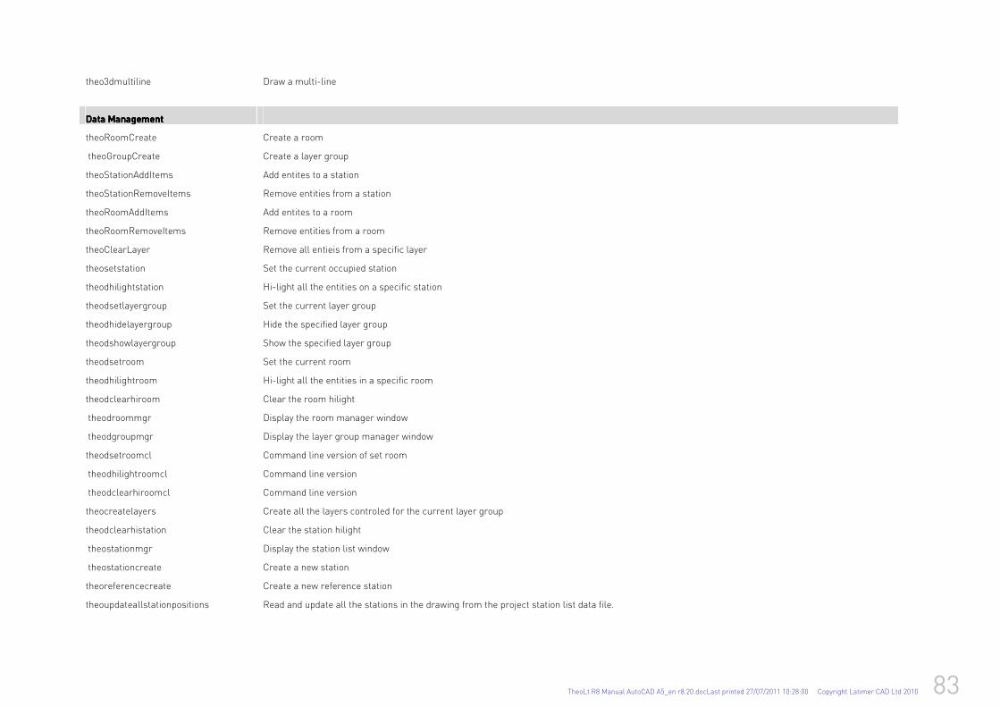
TheoLt R8 Manual AutoCAD A5_en r8.20.docLast printed 27/07/2011 10:28:00 Copyright Latimer CAD Ltd 2010 83
theo3dmultiline Draw a multi-line
Data Management Data Management Data Management Data Management
theoRoomCreate Create a room
theoGroupCreate Create a layer group
theoStationAddItems Add entites to a station
theoStationRemoveItems Remove entities from a station
theoRoomAddItems Add entites to a room
theoRoomRemoveItems Remove entities from a room
theoClearLayer Remove all entieis from a specific layer
theosetstation Set the current occupied station
theodhilightstation Hi-light all the entities on a specific station
theodsetlayergroup Set the current layer group
theodhidelayergroup Hide the specified layer group
theodshowlayergroup Show the specified layer group
theodsetroom Set the current room
theodhilightroom Hi-light all the entities in a specific room
theodclearhiroom Clear the room hilight
theodroommgr Display the room manager window
theodgroupmgr Display the layer group manager window
theodsetroomcl Command line version of set room
theodhilightroomcl Command line version
theodclearhiroomcl Command line version
theocreatelayers Create all the layers controled for the current layer group
theodclearhistation Clear the station hilight
theostationmgr Display the station list window
theostationcreate Create a new station
theoreferencecreate Create a new reference station
theoupdateallstationpositions Read and update all the stations in the drawing from the project station list data file.
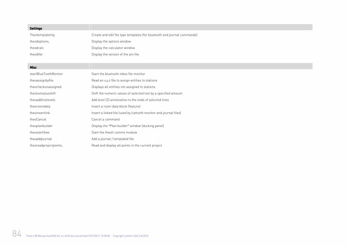
84 TheoLt R8 Manual AutoCAD A5_en r8.20.docLast printed 27/07/2011 10:28:00 Copyright Latimer CAD Ltd 2010
SettingsSettingsSettingsSettings
Theotemplatemg Create and edit file type templates (for bluetooth and journal commands)
theodoptions, Display the options window
theodcalc Display the calculator window
theodVer Display the version of the arx file
MiscMiscMiscMisc
startBlueToothMonitor Start the bluetooth inbox file monitor
theoassignbyfile Read an x,y,z file to assign entities to stations
theocheckunassigned Displays all entities not assigned to stations
theotextvalueshift Shift the numeric values of selected text by a specified amount.
theoaddlinelevels Add level (Z) annotoation to the ends of selected lines
theoroomdata Insert a room data block (feature)
theoinsertlink Insert a linked file (used by luetooth monitor and journal files)
theoCancel Cancel a command
theoplanbuilder Display the “Plan builder” window (docking panel)
theostarttheo Start the theolt comms module
theoaddjournal Add a journal / templated file
theoreadprojectpoints, Read and display all points in the current project

TheoLt R8 Manual AutoCAD A5_en r8.20.docLast printed 27/07/2011 10:28:00 Copyright Latimer CAD Ltd 2010 85
Appendix Appendix Appendix Appendix 3333: : : : TheoLt and TheoLt and TheoLt and TheoLt and DistToPlan DistToPlan DistToPlan DistToPlan layers layers layers layers listlistlistlist
DistToPlan DistToPlan DistToPlan DistToPlan Layers for Disto building plan data separation. DistToPlan will add these layers according to the commands used.
Walls_Disto Room outline
History_Disto Unadjusted lines ( frozen on default)
Annotation _Disto Dimension Text on wall line
Braces_Disto
Feedback Fixed points
Walls_Disto
Adjusted_Disto
Walls_Openings_Disto
Braces_Disto
Error_Lines_Disto
Error_Annotation_Disto
Annotation_Disto
Annotation_Adjusted_Disto
History_Disto Frozen on creation
Feature_Points_Disto
Align_Points_Disto
Fixed_Points_Disto
Hyperlinks
Heights
Windows_Dimension
Windows_Opening
Windows_Frame
Doors_Dimension
Doors
DoorOpening
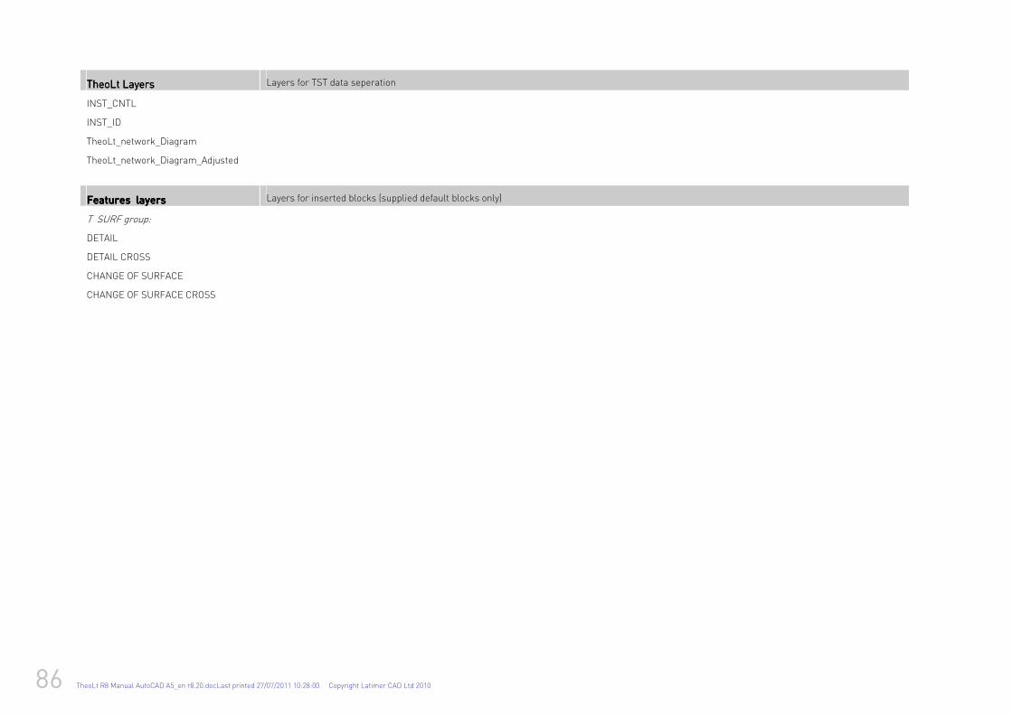
86 TheoLt R8 Manual AutoCAD A5_en r8.20.docLast printed 27/07/2011 10:28:00 Copyright Latimer CAD Ltd 2010
TheoLt LayersTheoLt LayersTheoLt LayersTheoLt Layers Layers for TST data seperation
INST_CNTL
INST_ID
TheoLt_network_Diagram
TheoLt_network_Diagram_Adjusted
Features layersFeatures layersFeatures layersFeatures layers Layers for inserted blocks (supplied default blocks only)
T SURF group:
DETAIL
DETAIL CROSS
CHANGE OF SURFACE
CHANGE OF SURFACE CROSS
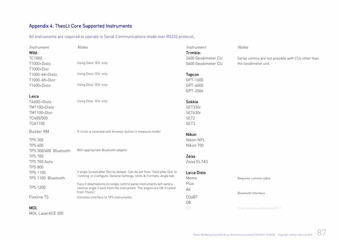
TheoLt R8 Manual AutoCAD A5_en r8.20.docLast printed 27/07/2011 10:28:00 Copyright Latimer CAD Ltd 2010 87
Appendix Appendix Appendix Appendix 4444: : : : TheoLt Core TheoLt Core TheoLt Core TheoLt Core Supported Instruments Supported Instruments Supported Instruments Supported Instruments All instruments are required to operate in Serial Communications mode over RS232 protocol.... Instrument Notes Instrument Notes Wild:Wild:Wild:Wild: Trimble:Trimble:Trimble:Trimble:
TC1000 3600 Geodimeter CU
T1000+Disto Using Disto ‘GSI’ only 5600 Geodimeter CU
Serial comms are not possible with CUs other than
the Geodimeter unit.
T1000+Dior
T1000-6K+Disto Using Disto ‘GSI’ only TopconTopconTopconTopcon
T1000-6K+Dior GPT-1000
T1600+Disto Using Disto ‘GSI’ only GPT-6000
GPT-2006
LeicaLeicaLeicaLeica
T460D+Disto SokkiaSokkiaSokkiaSokkia
TM1100+Disto
Using Disto ‘GSI’ only
SET330r
TM1100+Dior SET630r
TC400/500 SET2
TCA1100 SET3
Builder RM H circle is reversed with browser button in measure mode!
NikonNikonNikonNikon
TPS 300 Nikon NPL
TPS 400 Nikon 700
TPS 300/400 Bluetooth With appropriate Bluetooth adaptor
TPS 700 ZeissZeissZeissZeiss
TPS 700 Auto Zeiss ELTA3
TPS 800
TPS 1100 LeicaLeicaLeicaLeica DistoDistoDistoDisto
TPS 1100 Bluetooth Memo Requires comms cable
Plus TPS 1200
V angle locked after Dist by default. Can be set from ‘Hold after Dist to ‘running’ in Configure, General Settings, Units & Formats, Angle tab. Face 2 observations on single control panel instruments will send a reverse angle if sent from the instrument. The angles are OK if called from TheoLt
A6
Flexline TS Common interface to TPS instruments D3aBT
D8
Bluetooth Interface
MDLMDLMDLMDL 3D To be announced Autumn/2011
MDL LaserACE 300

88 TheoLt R8 Manual AutoCAD A5_en r8.20.docLast printed 27/07/2011 10:28:00 Copyright Latimer CAD Ltd 2010
TheoLt R8 Manual AutoCAD A5_en r8.20.docLast printed 27/07/2011 10:28:00 Copyright Latimer CAD Ltd 2010 89
For further help and advice please contact: Latimer CAD ltd,
Latimer-CAD
Worlds End Studios
132-134 Lots Road
London
SW10 0RJ
Phone:Phone:Phone:Phone: +44 (0)20 7349 7011
Fax:Fax:Fax:Fax: +44 (0)1403 272179
www.theolt.com