theoretical and applied fracture mechanics - … · a hole (fig. 1b) was drilled at the sawbones...
TRANSCRIPT

Theoretical and Applied Fracture Mechanics 85 (2016) 74–83
Contents lists available at ScienceDirect
Theoretical and Applied Fracture Mechanics
journal homepage: www.elsevier .com/locate / tafmec
Performance evaluation of dental implants: An experimental andnumerical simulation study
http://dx.doi.org/10.1016/j.tafmec.2016.08.0140167-8442/� 2016 Elsevier Ltd. All rights reserved.
⇑ Corresponding author.E-mail addresses: [email protected] (P. Bicudo), josealexandrereis@
gmail.com (J. Reis), [email protected] (A.M. Deus), [email protected] (L. Reis), [email protected] (M.F. Vaz).
P. Bicudo a, J. Reis b, A.M. Deus c, L. Reis a, M.F. Vaz a,⇑a IDMEC, Dep. Eng. Mecânica, Instituto Superior Técnico, Universidade de Lisboa, Av. Rovisco Pais, 1, 1049-001 Lisboa, PortugalbCiiEM, Instituto Superior de Ciências da Saúde Egas Moniz, Quinta da Granja, 2829-511 Almada, PortugalcCeFEMA, Dep. Eng. Mecânica, Instituto Superior Técnico, Universidade de Lisboa, Av. Rovisco Pais, 1, 1049-001 Lisboa, Portugal
a r t i c l e i n f o
Article history:Received 11 May 2016Revised 21 July 2016Accepted 19 August 2016Available online 24 August 2016
Keywords:Dental implantsFatigue testsNumerical simulations
a b s t r a c t
Dental implants are widely used in replacing missing teeth. However, some problems may occur such asscrew loosening or screw fracture which lead to implant failure. In this regard, it is of utmost importanceto analyse some of the factors that affect the primary stability and consequently the osseointegration ofdental systems. In the present study, particular attention is given to the bone density and the bone-implant contact in order to evaluate the implant performance.Given the difficulty in working with bone in vivo, in the present study two implant systems were
inserted in polymeric samples, of different densities, known as Sawbones, which simulate the structureof trabecular bone. The implant systems chosen were external hexagon and Morse taper. The perfor-mance of the implants was evaluated through experimental fatigue tests that simulate the chewing ormastication cycles. The qualitative analysis of the damage in the cellular structure of the samples wasperformed using scanning electron microscopy (SEM).The finite element (FE) method was used to model the penetration of the implants and enable the
determination of the stress at the implant and deformations at the Sawbones-implant vicinity. Prior topenetration simulations, a well-known analytical model of indentation was compared with indentationsimulations, in order to validate the numerical model. The major difference between numerical andanalytical model results, in the case of the displacements, was found to be around 9%.The failure of the Sawbones occurred with the propagation of the collapsed cells according to SEM
observations. The fatigue results showed that the Morse taper implant exhibited lower displacementsthan the external hexagon. Higher density Sawbones also exhibits lower deformations, while keepingthe other parameters constant. It means that Morse taper and high dense materials show a better fatigueperformance than the other systems and materials.The FE results for penetration showed that a threaded geometry implant when compared to smooth
geometry provided a reduction of the stresses in the implant and reduces the deformations in theSawbones.The results of the penetration simulations follow the same trend as the indentation simulations and
analytical model. Simulation results show that the displacements are reduced with the increase of thedensity of the polymer foam. This is in agreement with the fatigue results. Comparing bones with foams,it could be concluded that, the increase of the bone density will induce a higher stability of the implants.
� 2016 Elsevier Ltd. All rights reserved.
1. Introduction
In recent times dental implants have been considered a goodsolution for lack of dentition, being considered the best alternative
after natural teeth. However, in spite of the latest advances indentistry, implants are still likely to fail. Complications at thebone-implant interface, such as bone loss, occurrence ofmicromovements and stress concentration at the bone-implantinterface, are very common phenomena that affect the stabilityof the implant [1]. Two types of stability are defined, primaryand secondary, being the latter related to bone generation andremodelling. Although bone presents an adaptive behaviour dueto loading stimulus that consists in sequences of bone formation

Table 1Properties of the different foams and epoxy resin.
Sawbones 10 Sawbones 11 Sawbones 12 Epoxyresin
Density (g/cm3) 0.16 0.2 0.32 1.64Porosity (%) [13] 79.2 66.1 62.3 –Cell size (mm) 0.5–2 0.5–1.5 0.5–1 –Compressive
strength (MPa)2.3 3.9 5.4 157
Young’s modulus (MPa) 23 47.5 137 16.7Poisson’s ratio 0.3 0.3 0.3 0.26
Fig. 1. Preparation of the samples (a) Sawbone cube and epoxy resin layer; (b) ahole with a diameter of 4 mm (for external hexagon) or 4.5 mm (for the Morsetaper) was drilled according to the surgical protocol.
P. Bicudo et al. / Theoretical and Applied Fracture Mechanics 85 (2016) 74–83 75
and resorption, bone remodelling will not be considered in the pre-sent study. Therefore it is assumed that the density remainsconstant.
Primary stability is critical in the success of implants and is con-sidered to be a determining factor for osseointegration. Primarystability is related to an absence or to a high resistance to micro-movements. In fact, the dental micromovements must be less than150 lm in order to prevent implant failure [2]. Factors that influ-ence the primary stability are surface properties, surgical tech-nique, implant design or bone quality [3]. Bone quality isevaluated by density and quantity of trabecular and cortical bone[3]. When an implant is placed, the primary stability will depend,essentially, on the quantity of cortical and trabecular bone avail-able for the fixation of the implant [2].
Throughout time, the implants will be subject to different typesof loadings, resulting from the chewing and mastication process.This is why it is of the highest importance to submit dentalimplants to cyclic loading. Fatigue tests reproduce experimentallythe mastication process and allow evaluation of the long term sta-bility of an implant system in different substrates [4–6].
From a biomechanical perspective, a well-succeeded osseointe-gration of dental implant depends on how the stresses and defor-mations are transmitted to the bone and its surrounding tissues.The stress and strain distributions in bone and implant are affectedby many variables, such as the type of loading, the length anddiameter of the implant, its geometry, the bone-implant surface,and the quality and quantity of surrounding bone [7,8]. The FEmethod allows analysing the influence of the variables, and for thatreason it has become the most used simulation tool to analyse thefailure of the dental system.
Given the difficulties to work with trabecular bone, syntheticpolyurethane foams are widely used as alternative materials to thistype of bone in several biomechanical tests, due to the fact thatthese materials present a similar cellular structure and equivalentmechanical characteristics [9]. Sawbones are polymeric materialswhich are used as a standard material for performing mechanicaltests according to ASTM F-1839-08 [10].
Despite the fact that artificial foams have limitations and do notfully represent the real human jawbone, as their structural andmechanical properties aremuchmore homogeneous in comparisonwith in real bone, they are widely used in biomechanical testing,simulation and on the evaluation of implant stability [3,11–13]. Inthe experiments by Liu et al., three Sawbones foams were selectedwith densities of 0.16; 0.20; 0.32 g/cm3, named respectively Saw-bones 10, Sawbones 11 and Sawbones 12, to assess the relationbetween insertion torque and bone-implant contact area [13].
The density and the porosity of the mandibular bone vary withthe location (anterior, middle and distal) in the mandible [14].According to the Misch classification for bone density, bone typesD1, D2 and D3 can be found, being D1 the highest dense and D3the lowest dense bone [14]. In fact, D3 is formed by an open trabec-ular structure and a thin cortical part, while the D1 bone corre-sponds to a higher dense trabecular and cortical parts.
The aim of the present work was to study the effect of the tra-becular bone structure, in particular bone density, and bone-dentalimplant contact on the dental implant performance. Fatigue testswere performed according to the ISO 14801 standard with twoimplant systems: hexagonal external and cone Morse. Eachimplant was inserted in polymeric samples from Sawbones, withdifferent densities, simulating different bone types, to assess thestability of the implants and the deformations in the Sawbones-implant vicinity. This study was complemented with analyticaland numerical analyses. CAD geometries, similar to the test speci-mens, were generated, through which it was possible to generateFE meshes and subsequently determine the deformation fields ofthe Sawbones and the stress at the Sawbones-implant vicinity.
2. Materials and methods
2.1. Preparation of test specimens
The insertion material used consists on rigid polyurethanefoams, known as Sawbones acquired to the company Sawbones(Vashon Island, Washington, USA).
The three different densities of the Sawbones used were chosenby the present authors after carrying out an image analysis evalu-ation of the porosity of the trabecular bone found in the differentregions of the mandible. For the bone type D1, D2 and D3, the val-ues of the porosity obtained, in the present work, were respec-tively, 46, 56 and 72%. According to Liu et al., the porosity of theSawbones 12, 11 and 10 is 62.3, 66.1 and 79.2% (Table 1) [13]. Inview of the values of porosity of the Sawbones and porosity of boneD1, D2 and D3, one may establish a correlation between Sawbonesand bone type. In this sense, it could be assumed that the Sawbones10 with lower density aims to simulate a D3 bone type, theSawbones 12 represents a D1 bone type, and finally, the Sawbones11 is associated to a D2 bone type.
Cubic samples of Sawbones were prepared with dimensions of13 � 15 � 15 mm. In order to simulate the cortical part of the bone,an epoxy resin layer of thickness of 2 mm was glued to the polyur-ethane foam cubes (Fig. 1a). This is in accordance with the proce-dure defined by Liu et al. [13].
Although an implant system is formed by the implant, abut-ment, screw and crown, the present work will not feature thecrown. For the experimental fatigue tests, two types of implantswere tested: the external hexagon and the Morse taper with therespective abutments, shown in Fig. 2. Dental systems wereobtained from DIO, Busan, Korea. The identification of the implantmaterial was made through the chemical analysis carried out in afield emission gun scanning electron microscope (FEG–SEM) (JEOLmodel 7001F) with an X-ray energy-dispersive system (EDS). Theresults of such chemical analysis showed that the implants areproduced with commercially pure titanium grade 4.
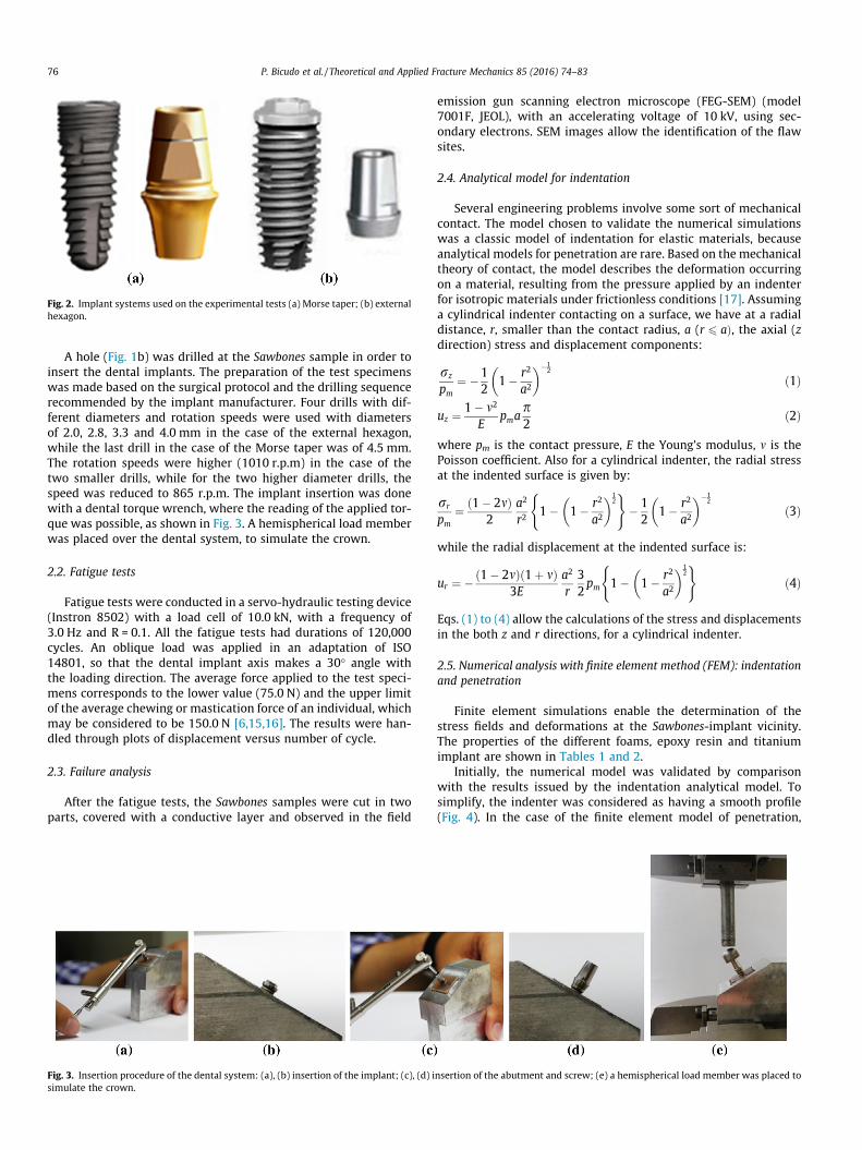
Fig. 2. Implant systems used on the experimental tests (a) Morse taper; (b) externalhexagon.
76 P. Bicudo et al. / Theoretical and Applied Fracture Mechanics 85 (2016) 74–83
A hole (Fig. 1b) was drilled at the Sawbones sample in order toinsert the dental implants. The preparation of the test specimenswas made based on the surgical protocol and the drilling sequencerecommended by the implant manufacturer. Four drills with dif-ferent diameters and rotation speeds were used with diametersof 2.0, 2.8, 3.3 and 4.0 mm in the case of the external hexagon,while the last drill in the case of the Morse taper was of 4.5 mm.The rotation speeds were higher (1010 r.p.m) in the case of thetwo smaller drills, while for the two higher diameter drills, thespeed was reduced to 865 r.p.m. The implant insertion was donewith a dental torque wrench, where the reading of the applied tor-que was possible, as shown in Fig. 3. A hemispherical load memberwas placed over the dental system, to simulate the crown.
2.2. Fatigue tests
Fatigue tests were conducted in a servo-hydraulic testing device(Instron 8502) with a load cell of 10.0 kN, with a frequency of3.0 Hz and R = 0.1. All the fatigue tests had durations of 120,000cycles. An oblique load was applied in an adaptation of ISO14801, so that the dental implant axis makes a 30� angle withthe loading direction. The average force applied to the test speci-mens corresponds to the lower value (75.0 N) and the upper limitof the average chewing or mastication force of an individual, whichmay be considered to be 150.0 N [6,15,16]. The results were han-dled through plots of displacement versus number of cycle.
2.3. Failure analysis
After the fatigue tests, the Sawbones samples were cut in twoparts, covered with a conductive layer and observed in the field
Fig. 3. Insertion procedure of the dental system: (a), (b) insertion of the implant; (c), (d) isimulate the crown.
emission gun scanning electron microscope (FEG-SEM) (model7001F, JEOL), with an accelerating voltage of 10 kV, using sec-ondary electrons. SEM images allow the identification of the flawsites.
2.4. Analytical model for indentation
Several engineering problems involve some sort of mechanicalcontact. The model chosen to validate the numerical simulationswas a classic model of indentation for elastic materials, becauseanalytical models for penetration are rare. Based on the mechanicaltheory of contact, the model describes the deformation occurringon a material, resulting from the pressure applied by an indenterfor isotropic materials under frictionless conditions [17]. Assuminga cylindrical indenter contacting on a surface, we have at a radialdistance, r, smaller than the contact radius, a (r 6 aÞ, the axial (zdirection) stress and displacement components:
rz
pm¼ �1
21� r2
a2
� ��12
ð1Þ
uz ¼ 1� m2
Epma
p2
ð2Þ
where pm is the contact pressure, E the Young’s modulus, m is thePoisson coefficient. Also for a cylindrical indenter, the radial stressat the indented surface is given by:
rr
pm¼ ð1� 2mÞ
2a2
r21� 1� r2
a2
� �12
( )� 12
1� r2
a2
� ��12
ð3Þ
while the radial displacement at the indented surface is:
ur ¼ �ð1� 2mÞð1þ mÞ3E
a2
r32pm 1� 1� r2
a2
� �12
( )ð4Þ
Eqs. (1) to (4) allow the calculations of the stress and displacementsin the both z and r directions, for a cylindrical indenter.
2.5. Numerical analysis with finite element method (FEM): indentationand penetration
Finite element simulations enable the determination of thestress fields and deformations at the Sawbones-implant vicinity.The properties of the different foams, epoxy resin and titaniumimplant are shown in Tables 1 and 2.
Initially, the numerical model was validated by comparisonwith the results issued by the indentation analytical model. Tosimplify, the indenter was considered as having a smooth profile(Fig. 4). In the case of the finite element model of penetration,
nsertion of the abutment and screw; (e) a hemispherical load member was placed to

Table 2Properties of titanium grade 4 [19].
Density (g/cm3) 4.55Young’s modulus (GPa) 120Tensile yield strength (elastic limit) (MPa) 570Tensile strength (MPa) 690Compressive strength (MPa) 400Poisson’s ratio 0.37
P. Bicudo et al. / Theoretical and Applied Fracture Mechanics 85 (2016) 74–83 77
two distinct geometries for the implants were considered, onesmooth and other threaded. The SolidWorks 2015 program wasused to generate CAD files that were subsequently exported tothe ANSYS Workbench 14.5 commercial code. The CAD geometriesand the meshes used in the FE simulations are indicated in Fig. 4.
Penetration simulations were performed with two geometriesof the implant, smooth and threaded, while on the indentationmodel only the smooth geometry was studied. To generate themesh of smooth geometry implant the element SOLID186 was usedwhile for the threaded geometry implant the element SOLID187was applied.
The convergence test of the FE models was performed to verifythe mesh quality, and the convergence criterion was set to be lessthan 7% changes in the highest von Mises stress. The mesh conver-gence error stayed below that threshold, both for smooth geometry(6.97%), as well as in the case of comparison with the threadedimplant (6.83%). For the penetration simulations, the number ofelements in the mesh was 37,731 for the smooth implant and187,823 for the threaded geometry. The mesh used in the indenta-tion simulations had 19,572 elements. Element sizes were0.48 mm (smooth implant penetration), 0.58 mm (threadedimplant penetration) and 0.6 mm (smooth implant indentation).
The epoxy layer, implant and bone substitute were consideredhomogeneous, isotropic and linear elastic materials [16,18].
Initially the numerical simulations of penetration were madewith the type of contact designated as bonded of the ANSYS code,
Fig. 4. CAD geometries of (a) smooth geometry and (b) threaded geometry of implant useimplant; (e) mesh of assembled parts used in the indentation simulations.
in order to reproduce a good osseointegration of the implant. How-ever, the type of contact between Sawbone and epoxy with theimplant was changed to no separation, which allows for, limitedbut frictionless, sliding between surfaces. This second type of con-tact was found to simulate better the penetration of the implantsystem on the surface of the foam due to the complexity involvingthe foam microarchitecture.
For the boundary conditions, the lateral faces of the epoxy andall the Sawbone faces were constrained in the three directions, x, yand z.
Penetration simulations were undertaken for the three types ofSawbones and for two applied loads, 70.0 and 150.0 N, while theloads, for the indentation case, were 60.6 N and 129.9 N.
The von Mises criterion (invariant) was used to compute thestresses.
3. Results
3.1. Fatigue tests
The curves obtained in the fatigue tests for the implant systemsexternal hexagonal and Morse taper inserted in Sawbones 10, 11and 12 are exhibited in Figs. 5–7. The explanation of the shape ofthe displacement-number of cycles curves take into account thatin cellular solids, the mechanisms associated with the stress-strain compressive curves are the same as the ones of the distinctzones of the displacement – number of cycles curves [20,21].
The curves revealed that in a first stage and for a low number ofcycles the materials response was essentially linear elastic. Therewas a rapid accumulation of deformation caused by the bendingand stretching of the cell walls, until the yield point, which wasassociated with the collapse of the first cell. Then, after overcomingthis peak, there was a slight decrease of deformation as a result ofthe softening of the material. At the end of this phase, starts a levelwhere the deformation in the material increases slightly with the
d in the penetration simulations; (c) mesh of smooth implant; (d) mesh of threaded

Fig. 5. Fatigue curves obtained with: (a) external hexagon implant; (b) Morse taper implant, inserted into Sawbones 10.
Fig. 6. Fatigue curves obtained with: (a) external hexagon implant; (b) Morse taper implant, inserted into Sawbones 11.
Fig. 7. Fatigue curves obtained with: (a) external hexagon implant; (b) Morse taper implant, inserted into Sawbones 12.
78 P. Bicudo et al. / Theoretical and Applied Fracture Mechanics 85 (2016) 74–83
number of cycles. It was during this phase that occurred the plasticcollapse phenomenon [22].
The applied load has an effect in the experimental fatigueresults. Curves obtained with the external hexagonal system andSawbones 10, which is the foam with the worst mechanical beha-viour, with F = 75.0 N, show no increase in the deformation in thecollapse zone, while for F = 150.0 N there is an increase of deforma-tion with the number of cycles. However in the fatigue curvesacquired with Morse taper and Sawbones 10, with the loadsF = 75.0 N and F = 150.0 N, the deformation does not change muchwith the number of cycles, being the progress of the two curvessubstantially the same. Apart from the shape of the curves, onemay note that at the end of fatigue tests, N = 120,000 cycles,keeping the same dental system and Sawbones, an increase in loadimplies higher deformations.
With the exception of fatigue tests performed with the Saw-bones 10 that exhibits a different behaviour from the others, onemay state that at the end of the test, displacements are lower with
Morse taper than with external hexagonal, under the same loadconditions and the same Sawbones. Results obtained with the samedental system and applied load showed that the displacements forN = 120,000 cycles are lower for the highest density Sawbones. Itmeans that a better fatigue behaviour is obtained with the Morsetaper system and the highest density foam.
3.2. FEM indentation simulations and analytical model
Eqs. (1) to (4) of the analytical model were used to evaluate thedeformation and the stress at a radial distance r=a ¼ 0:5, with con-tact radius a = 2 mm. The Sawbones entire displacement was calcu-
lated as u ¼ffiffiffiffiffiffiffiffiffiffiffiffiffiffiffiffiffiffiffiffiffiffiffiffiffiffiffiðuzÞ2 þ ðurÞ2
q, while the whole stress was
r ¼ffiffiffiffiffiffiffiffiffiffiffiffiffiffiffiffiffiffiffiffiffiffiffiffiffiffiffiffiðrzÞ2 þ ðrrÞ2
q. The numerical simulations of indentation are
shown in Fig. 8, where the deformation and the stress fields areplotted.

Fig. 8. Numerical simulations results of indentation (a) deformation field; (b) stress field, for Sawbones 10 and F = 60.62 N.
Table 3Analytical and numerical results for indentation.
F(N) Analytical model Numerical simulations
u (mm) r (MPa) u (mm) r (MPa)
Sawbones 10 60.62 0.600 3.592 0.551 3.403Sawbones 10 129.90 1.286 7.697 1.180 7.292Sawbones 11 60.62 0.291 3.592 0.267 3.404Sawbones 11 129.90 0.623 7.697 0.571 7.293Sawbones 12 60.62 0.101 3.592 0.092 3.406Sawbones 12 129.90 0.216 7.697 0.198 7.298
Fig. 9. Numerical simulations results of penetration displacement/deformation of the three types of materials; (a) Sawbones 10; (b) Sawbones 11; (c) Sawbones 12, forF = 70.0 N and a smooth geometry of the implant.
P. Bicudo et al. / Theoretical and Applied Fracture Mechanics 85 (2016) 74–83 79
Table 3 indicates both numerical and analytical results for thethree types of Sawbones and two values of the applied load. Theanalytical equations validated the finite element model, havingmanifested a 9.1% relative error for displacements and 5.5% forstresses. The stresses calculated by the analytical equations arenot sensitive to the bulk properties of the Sawbones, as only thePoisson ratio is included and it has the same value of 0.3, for thethree Sawbones.
The results of numerical simulations and analytical calculationsshowed that the deformation values decrease for the Sawboneswith higher density and higher stresses.
3.3. FEM penetration simulations
Examples of the numerical results of the penetration simula-tions with a smooth indenter with the same applied load are givenin Figs. 9 and 10, where the deformation at the Sawbones (Fig. 9)and the stress at the implant vicinity - Sawbones (Fig. 10) areshown. One may notice that the maximum stress is achieved atthe contact zone of the implant and the epoxy resin.
From Figs. 9 and 10, it can be noted that the deformations of thethree different Sawbones are different among each other and, as thedensity of the foam increases, the displacements and the stresseswere found to decrease. From the point of view of stress analysis,it can be said that the most favourable situation occurs with the
denser Sawbones, because the stress values were minimized.Regarding the deformations on Sawbones, it was in the less densethan the highest values occurred. Given the nature of the appliedcompressive force at the implant, the maximum deformationoccurred at the contact vicinity between the implant base andthe Sawbones, a situation which was found for all values of densityand intensity load tested. As the load increases from 70.0 N to150.0 N, the displacements in the Sawbones were also higher.
The results of the threaded geometry of the implant were verysimilar to those previously found for the smooth geometry (Table 4and Fig. 11). For example, an increase of the Sawbones density isreflected in a reduction of deformation and stress.
The threaded geometry provided a reduction of the stresses inthe implant and reduces the deformations in the Sawbones in com-parison with the smooth geometry. In fact, a threaded implantinduces a larger contact area of the vicinity between the implantand the Sawbones when compared to a smooth profile, which pro-motes a reduction in the amount of stress, while maintaining thesame loading.
3.4. SEM observations and failure analysis
Through the SEM observations of the longitudinal sections ofthe Sawbones after the fatigue tests, it was possible to identifythe regions of the collapsed cells (Fig. 12). It was observed that

Fig. 10. Numerical simulations results of penetration: stress at the implant interface-Sawbones; (a) Sawbones 10; (b) Sawbones 11; (c) Sawbones 12, for F = 70.0 N and asmooth geometry of the implant.
Table 4Numerical results for penetration with implant geometry smooth and threaded(F = 150 N).
Smooth Threaded
u (mm) r (MPa) u (mm) r (MPa)
Sawbones 10 0.567 4.375 0.556 3.609Sawbones 11 0.292 4.573 0.278 3.850Sawbones 12 0.106 4.672 0.101 4.123
Fig. 12. SEM images (a) Sawbones 10; (b) Sawbones 12, after fatigue tests withexternal hexagon systems. A contour line for the affected area is represented.
80 P. Bicudo et al. / Theoretical and Applied Fracture Mechanics 85 (2016) 74–83
the number of collapsed cells within the affected area were largerfor the less dense structure. The damage of the samples is higherfor the lowest dense material which has the lowest yield stress,in a way that the collapse starts at lower loads than in case ofthe dense foam. One may observe that the collapse of cells isaccompanied with the fracture of the cell walls, which resemblesreal bone where there is the formation of microcracks in individualtrabeculae at early stages of fatigue testing [20].
4. Discussion
Implant stability is difficult to evaluate as it depends on severalfactors such as mechanical design, geometry and quality of bone,applied load and contact area between implant and bone.
Cyclic behaviour of dental implant systems inserted intopolymeric foams is an effective way to reproduce the mastication
Fig. 11. Numerical simulations results of penetration (a) displacement/deformation atF = 70.0 N and a threaded geometry of the implant.
process in the laboratory. During mastication, the load may varyin accordance to higher/lower efforts made by teeth. The effect ofthe variation of the applied load was detected in the present fati-gue tests, which revealed that an increase in the applied load leadto larger displacements at the Sawbones, for the same number ofcycles, support foam and dental system.
Differences were detected on the fatigue behaviour obtained forthe two tested implant systems. Tests made with the same load
the Sawbones; (b) stress at the implant interface -Sawbones, for Sawbones 10 and
P. Bicudo et al. / Theoretical and Applied Fracture Mechanics 85 (2016) 74–83 81
and Sawbones, but different implant systems, showed that at theend of same number of cycles, the displacements at the foamsare lower for the Morse taper system. Also, this type of implantwas less sensitive to load variation when it was tested with thesame cell structure. Both external hexagonal and Morse taper sys-tems inserted into different density Sawbones provided lower dis-placements with the highest dense foam. This means that thestructure of the Sawbones was able to accommodate the move-ments of the implant. From the point of view of the bone structure,this means that a D1 bone type, being denser and mechanicallystronger than the other types of bones, will induce lowerdisplacements.
At the end of the fatigue tests, SEM observations revealed thatthe highest density material was less damaged than the otherswith lower density, having also a lower number of collapsed cells.
The present results confirm the good performance of the Morsetaper system, when compared with the behaviour of the externalhexagonal implant. The success is due to its ‘‘locking mechanism”,because the shape of the system is designed to reduce vibrationsand micromovements [23]. In fact, the introduction of micro-threads in the implant neck region helps to minimize the amountof stresses along that zone, resulting in a decrease of bone loss afterthe placement of the implant [2]. Also the Morse taper implant hasa higher diameter and length in comparison with external hexa-gon. Increasing the implant diameter promotes a reduction in thenormal and shear stresses along the bone-implant vicinity, leadingto a better distribution of loads in the tissue [16,18].
An analysis of the stresses on the implant and bone is importantto carry out, since both structures should not be stressed beyond acertain value [24,25]. The stress analysis was performed using thefinite element method.
A validation of the FE simulations was conducted using ananalytical model of indentation. Differences in the numerical andanalytical results, in the case of the displacements, were around9%, which enable to proceed to other FE calculations as thepenetration simulations. Indentation results also show thatSawbones of high density give rise to lower values ofdisplacements.
Larger stress concentrations were found at the contact zone ofimplant-epoxy resin, which is accordance with other simulations
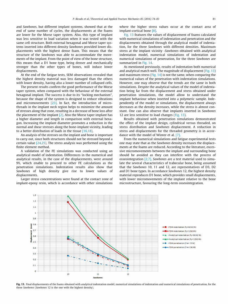
Fig. 13. Final displacements of the foams obtained with analytical indentation model, nuthree Sawbones (Sawbones 12 is the one with the highest density).
where the higher stress values occur at the contact area ofimplant-cortical bone [8].
Fig. 13 features the values of displacement of foams calculatedwith numerical simulations of indentation and penetration and thedisplacements obtained through the analytical model of indenta-tion, for the three Sawbones with different densities. Maximumstress at the implant vicinity -Sawbones obtained with analyticalindentation model, numerical simulations of indentation andnumerical simulations of penetration, for the three Sawbones aresummarized in Fig. 14.
As mentioned previously, results of indentation both numericaland analytical match well. The magnitude of displacement (Fig. 13)and maximum stress (Fig. 14) is not the same, when comparing thenumerical values of the penetration with indentation simulations.However, one may observe that the trends are the same in bothsimulations. Despite the analytical values of the model of indenta-tion being far from the displacement and stress obtained underpenetration simulations, the model allow to understand theimplant behaviour when inserted into a polymeric sample. Inde-pendently of the model or simulations, the displacement alwaysdecreases as the density increases, while the stress is almost con-stant. One can also observe that implants inserted in Sawbones12 are less sensitive to load changes (Fig. 13).
Results obtained with penetration simulations demonstratedthe effect of the implant design, cylindrical versus threaded, onstress distribution and Sawbones displacement. A reduction instress and displacements for the threaded geometry is in accor-dance with the model of Winter et al. [7].
From the numerical simulations and fatigue experimental testsone may state that as the Sawbones density increases the displace-ments at the foams are reduced. According to the literature, exces-sive micromovements between the implant and surrounding boneshould be avoided as they can interfere with the process ofosseointegration [2,7]. Sawbones are a test material used to simu-late the several characteristics of trabecular bone, being assumedthat the Sawbones 10, 11 and 12, are representatives of D3, D2and D1 bone types. In accordance Sawbones 12, the highest densitymaterial reproduces D1 bone, which provides small displacements,with lower micromovements of the implant relative to the bonemicrostructure, favouring the long-term osseointegration.
merical simulations of indentation and numerical simulations of penetration, for the

Fig. 14. von Mises maximum stress at the implant interface - Sawbones obtained with analytical indentation model, numerical simulations of indentation and numericalsimulations of penetration, for the three Sawbones (Sawbones 12 is the one with the highest density).
82 P. Bicudo et al. / Theoretical and Applied Fracture Mechanics 85 (2016) 74–83
5. Conclusions
The effects of the trabecular bone density, bone-implant contactand design on the dental implant performance were evaluated.These aspects are of clinical importance as they affect, forexample, the strain in the trabecular bone, which is not wellunderstood.
The analysis of the experimental fatigue behaviour of implants,external hexagon and Morse taper, inserted on different substrateswas complemented with an analytical and finite element study, inorder to calculate the stress and strain distributions in the implantand in the bone. As trabecular bone is difficult to obtain, Sawbonesfoams were used as substrate materials.
SEM observations of the samples at the end of fatigue testsindicate that the failure of the Sawbones happened with the prop-agation of the collapsed cells, the collapse regions being larger inthe case of the lowest dense foam.
The results of the fatigue tests showed that the performance ofthe Morse taper implant (higher diameter and length) was betterthan the external hexagonal implant when both were tested insamples of various densities, as it leads to smaller displacements.This superior fatigue behaviour presented by Morse taper systemexplains its increased choice in clinical applications. The highestdensity Sawbones was the one that showed the lowest deforma-tion, exhibiting a better fatigue performance.
An analytical model validated the numerical simulationsfor indentation using the FE method. The displacement andstress results obtained with the penetration FE model exhibit thesame trend as the analytical results and FE indentationsimulations, so that apart from a scale factor, the analytical modelof indentation can be a starting point for the interpretation ofresults.
Finite element simulations with a thread geometry implantshowed reductions of stress in the implant and smaller deforma-tions in the Sawbones.
Results of the numerical simulations indicate that as the densityof the foam increases, the displacements are reduced which is inaccordance with the fatigue experimental tests.
Acknowledgements
This work was supported by FCT, through IDMEC, under LAETA,project UID/EMS/50022/2013.
References
[1] V. Mathieu, R. Vayron, G. Richard, G. Lambert, S. Naili, J.P. Meningaud, G. Haiat,Biomechanical determinants of the stability of dental implants: Influence ofthe bone-implant interface properties, J. Biomech. 47 (2014) 3–13.
[2] F. Javed, G. Romanos, The role of primary stability for successful immediateloading of dental implants: a literature review, J. Dent. 38 (2010) 612–620.
[3] C. Elias, F. Rocha, A. Nascimento, P. Coelho, Influence of implant shape, surfacemorphology, surgical technique and bone quality on the primary stability ofdental implants, J. Mech. Behav. Biomed. 16 (2012) 169–180.
[4] J. Ayllon, C. Navarro, J. Vazquez, J. Dominguez, Fatigue life estimation in dentalimplants, Eng. Fract. Mech. 123 (2014) 34–43.
[5] K. Shemtov-Yona, D. Rittel, L. Levin, E. Machtei, Effect of dental implantdiameter on fatigue performance. Part I: Mechanical behavior, Clin. Implant.Dent. R. 16 (2014) 172–177.
[6] F. Gil, M. Herrero-Climent, P. Lazaro, J. Rios, Implant-abutment connections:influence of the design on the microgap and their fatigue and fracture behaviorof dental implants, J. Mater. Sci.-Mater. M. 25 (2014) 1825–1830.
[7] W. Winter, D. Klein, M. Karl, Micromotion of dental implants: basic mechanicalconsiderations, J. Med. Eng. 265412 (2013) 1–9.
[8] B. Ali, E.B.O. Chikh, H.M. Meddah, A. Merdji, B.A.B. Bouiadjra, Effects ofoverloading in mastication on the mechanical behaviour of dental implants,Mater. Des. 47 (2013) 210–217.
[9] V. Palissery, M. Taylor, M. Browne, Fatigue characterization of a polymer foamto use as a cancellous bone analog material in the assessment of orthopaedicdevices, J. Mater. Sci.-Mater. M. 15 (2004) 61–67.
[10] American Society for Testing and Materials ASTM F1839–08 standardspecification for rigid polyurethane foam for use as a standard material fortesting orthopaedic devices and instruments. American Society for Testing andMaterials, West Conshohocken, 2008.
[11] V. Shim, J. Boheme, C. Josten, I. Anderson, Use of polyurethane foam inorthopaedic biomechanical experimentation and simulation, in: F. Zafar, E.Sharmin (Eds.), Polyurethane, InTech, Croatia, 2012 (Chapter 9).
[12] M.S. Thompson, I.D. McCarthy, L. Lidgren, L. Ryd, Compressive and shearproperties of commercially available polyurethane foams, J. Biomech. Eng. –Trans. ASME 125 (2003) 732–734.
[13] C. Liu, M.-T. Tsai, H. -Li Huang, M.Y.-C. Chen, J.-T. Hsu, K.-C. Su, C.-H. Chang, A.Y.-J. Wu, Relation between insertion torque and bone–implant contactpercentage: an artificial bone study, Clin. Oral Invest. 16 (2012) 1679–1684.
[14] C.E. Misch, Density of bone: effects on surgical approach and healing, in: C.E.Misch (Ed.), Contemporary Implant Dentistry, Mosby, Elsevier, Canada, 2008,pp. 645–667.

P. Bicudo et al. / Theoretical and Applied Fracture Mechanics 85 (2016) 74–83 83
[15] J.F.S. Junior, F.R. Verri, D.A.F. Almeida, V.E.S. Batista, C.A.A. Lemos, E.P. Pellizzer,Finite element analysis on influence of implant surface treatments, connectionand bone types, Mat. Sci. Eng. C 63 (2016) 292–300.
[16] H. Huang, J. Hsu, L. Fuh, M. Tu, C. Ko, Y. Shen, Bone stress and interfacial slidinganalysis of implant designs on an immediately loaded maxillary implant: anon-linear finite element study, J. Dent. 36 (2008) 409–417.
[17] A.C. Fischer-Cripps, Introduction to Contact Mechanics, MechanicalEngineering Series, Springer, US, 2007.
[18] S. Faegh, S. Muftu, Load transfer along the bone-dental implant interface, J.Biomech. 43 (2010) 1761–1770.
[19] CES 2015, EduPack 2015, The Cambridge Engineering Selector, Granta Design,2015.
[20] S. Dendorfer, H. Maier, J. Hammer, Fatigue damage in cancellous bone: anexperimental approach from continuum to micro scale, J. Mech. Behav.Biomed. 2 (2009) 113–119.
[21] S. Dendorfer, H. Maier, D. Taylor, J. Hammer, Anisotropy of the fatiguebehaviour of cancellous bone, J. Biomech. 41 (2008) 636–641.
[22] M.F. Ashby, The mechanical properties of cellular solids, Metall. Mater. Trans.A 14 (1983) 1755–1769.
[23] A. Khraisat, R. Stegaroiu, S. Nomura, O. Miyakawa, Fatigue resistance of twoimplant/abutment joint designs, J. Prosthet. Dent. 88 (2002) 604–610.
[24] H. Duarte, J. Andrade, L. Dinis, R. Jorge, J. Belinha, Numerical analysis of dentalimplants using a new advanced discretization technique, Mech. Adv. Mat.Struct. 23 (2016) 467–479.
[25] O. Kayabasi, E. Yuzbasioglu, F. Erzincanli, Static, dynamic and fatigue behaviorsof dental implant using finite element method, Adv. Eng. Softw. 37 (2006)649–658.