theoretical and experimental evaluation of pulse jet engine · pulsejet engine. it has a chamber...
TRANSCRIPT

بسم اهللا الرحمن الرحيم
University of Khartoum
The Graduate College
Theoretical and Experimental Evaluation of Pulse Jet Engine
A thesis submitted in partial fulfillment of the requirements
for the degree of M.Sc. in Energy Engineering
Prepared by:
Hussain Sadig Hussain
Supervised by:
Dr. Ali Omer Ahmed
May 2008

II
Acknowledgements
I would like to acknowledge Toner Engineering family, for supporting me in
my research, my advisor, Dr Ali Omer, for his advice and assistant; and the support
received from all family and friends.

III
خلصستالم
من ناحية ) Pulse Jet Engine (الهدف من هذا البحث هو دراسة ماكينة الدفع النفثي المتقطع
االستهالك للماكينة و التي تشمل األداءالمعامالت البعدية و معامالت ثيرموديناميكية باإلضافة لدراسة
.الدفع و التردد،النوعي للوقود
أيضاً تم . رطل100 دفع مقداره إلنتاجميم ماكينة دفع نفثي متقطع تم التحصل علي األبعاد المطلوبة لتص
).Petal Valve System(من نوع تصميم منظومة للتحكم في دخول الهواء المطلوب لتغذية الماكينة
IV
Abstract
The objective of this research is to understand the thermodynamic characteristics
of conventional pulse jet engine.
The geometrical parameters and performance aspects of the engine were studied
including specific fuel consumption, thrust and frequency limitations.
Calculation were made on geometrical parameters for a deign of a pulse jet engine
of 100 lb thrust.
Petal valve were selected for their simplicity to control air flowing to the engine.

V
Table of Content
List of Figures......................................................................................................................................VII
List of Tables .................................................................................................................................... VIII
Nomenclature ....................................................................................................................................... IX
1 Introduction....................................................................................................... 1
1.1 Pulse Jet Engines......................................................................................... 1
1.2 How Does Valve less Pulsejet Work........................................................... 2
1.3 Kadenacy Effect.......................................................................................... 5
1.4 Advantages of Pulse Jet Engine .................................................................. 6
1.5 Limitations of Pulse jet Engine ................................................................... 7
1.6 Objectives of this Project ............................................................................ 8
2 Literature Review ............................................................................................. 9
2.1 Historical Review........................................................................................ 9
2.2 Development in Valve less Pulse jet engine ............................................. 14
3 Theory of Operation ....................................................................................... 17
3.1 Unsteady Propulsive Devices.................................................................... 17
3.2 Pulsejet Cycle............................................................................................ 18
3.3 Pulsejet Cycle Theory ............................................................................... 19
3.4 Thermodynamic Analysis of Pulsejet Engine ........................................... 22
3.5 Frequency of pulsation of pulse jet Engines ............................................. 26
3.6 Trust of pulse jet Engines.......................................................................... 28
4 Designing principles ....................................................................................... 31
4.1 Engine Diameter ......................................................................................... 31
4.2 Engine Effective Length ............................................................................. 32
4.3 Valve Area .................................................................................................. 33
4.4 Valve System .............................................................................................. 33
4.4.1 Petal Valves........................................................................................ 34

VI
4.4.1 The V or multi-V valve ...................................................................... 35
4.5 Combustion Chamber ................................................................................ 37
4.6 Joint The combustion Chamber With Tail Pipe ........................................ 38
4.7 Fuel Systems ............................................................................................... 40
4.7.1 Atomization ....................................................................................... 41
4.7.2 Injection ............................................................................................. 42
4.7.3 Timed Injection.................................................................................. 43
5 Results And Recommendation ...................................................................... 44
References ............................................................................................................. 49

VII
List of Figures
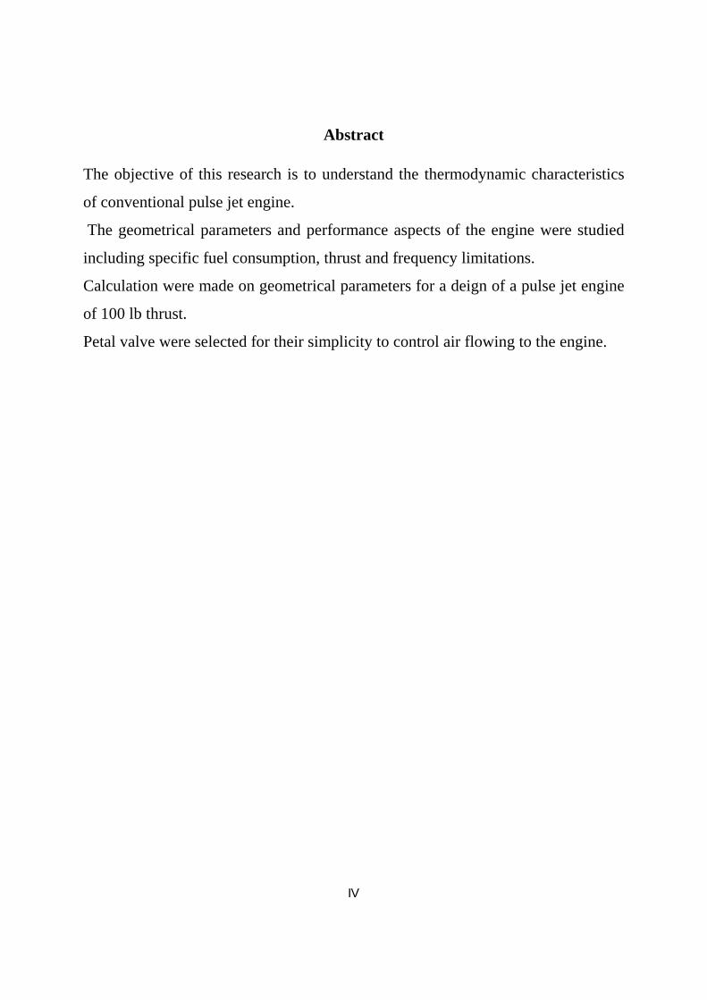
1.1 Schematic of a valved pulsejet ....................................................................... 1
1.2 Valve less Pulsejet ......................................................................................... 2
1.3 Pulse jet with concave ring baffles in the intake tract .................................... 4
1.4 Pulse jet with baffles/serrations ...................................................................... 5
1.5 Pressure oscillations in the combustion chamber ........................................... 5
2.1 A schematic of the Esnaut-Peltrie push-pull combustion engine .................. 11
2.2 A schematic of the Marconnet valve less pulsejet.......................................... 12
2.3 The Schmidt tube ........................................................................................... 13
2.4 The V-2 'Buzz Bomb ..................................................................................... 13
2.5 The French 'Escopette' valveless pulsejet....................................................... 14
2.6 Schematic of the Hiller-Lockwood pulsejet ................................................... 16
3.1 Summary of Detonation Cycle....................................................................... 18
3.2 Lenoir Cycle................................................................................................... 18
3.3 Humphrey Cycle ............................................................................................ 19
3.4 Diagram Showing Pressure and Velocities in the Schmited Tube C-D
Air inflow at the open end,A-B vlved open,Z cycle time............................... 20
3.5 Pressure Distribution at the Beginning and the End Of combustion .............. 27
4.1 Engine Dimension.......................................................................................... 32
4.2 Petal valve...................................................................................................... 35
4.3 V- Valve......................................................................................................... 36
4.4 Engine combustion chamber .......................................................................... 37
4.5 Dynajet engine Petal valve front view ........................................................... 38
4.6 Jointing the combustion chamber with tail pipe............................................. 39
4.7 Simple diagram for atomization..................................................................... 42
4.7 Petal valve front view .................................................................................... 46

VIII
5.2 Joint combustion chamber with tail pipe using 300 cone ............................... 48

IX
List of Tables 4.1 The ratio The ratio (L/Dm) in Dynajet and V1 engines ………………..33

X
Nomenclature
P Pressure M Mach number
Specific heat rate T Temperature
Specific heat at constant volume Specific heat at constant pressure
Enthalpy Discharge velocity corresponding to p
Density
a Velocity of Sound
Combustion efficiency
H Heat value of the fuel per lb
Frequency of oscillation
F Thrust of the engine
Thrust coefficient
� Pressure Ratio
S Specific Fuel Consumption
V Engine volume
L Engine effective length
Va Valve area
Ah Petal valve area
Dh Petal valve hole diameter
Dc Combustion chamber length
Lc Combustion chamber joint length
1
CHAPTER ONE
INTRODUCTION
1.1 Pulse Jet Engines:
The pulsejet is a compressor less, unsteady flow jet engine
without wave pre-compression of the combustible charge. A pulsejet
is mechanically very simple and consists of a short inlet diffuser
leading to a set of flow check valves, followed by a combustion
chamber and a shaped tube, as shown in Figure 1.1. A fuel injection
system is located downstream of the valves. The air flowing into the
engine through the valves is mixed with a fuel spray, and the mixture
is ignited. As a result of the pressure rise generated by the explosion,
the inlet flow check valves close and the exhaust gases expand outside
through the exhaust tube. The exhaust of the burned gases generates
expansion waves that reduce the pressure behind the check valves
until they open again and a fresh charge of air enters. The cycle is
then repeated. A spark is required only to start because after the first
cycle, the hot gases from the previous cycle ignite the fresh
combustible charge. The most common version of the pulsejet is the
valved pulsejet; however, there exist valve less pulsejets.
Figure 1.1: Schematic of a valved pulsejet
2
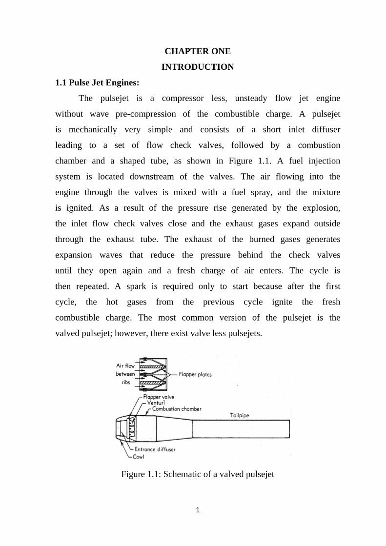
1.2 How Does Valve less Pulsejet Work?
Figure 1.2 shows one of the possible layout of a valve less
pulsejet engine. It has a chamber with two tubular ports of unequal
length and diameter. One port, curved backwards, is the inlet pipe
and the other (flared at the end) is the tail pipe. In some other valve
less engines, it is the exhaust pipe that is bent into the U-shape, but
the important thing is that both ports point in the same direction.
Figure 1.2: Valve less Pulsejet
When the fuel-air mixture combusts in the chamber, the
pressure inside rises very suddenly. The rising pressure forces the hot
gas to expand out of the chamber and pass through the two ports at
high speed. As it leaves the engine, the hot gas exerts thrust.
As the gas expands, the pressure inside the chamber drops.
Due to inertia, the expansion continues even after the pressure falls
back to atmospheric. At the lowest point, there is partial vacuum in
the chamber. At that point, the momentum of the expanding gas is
spent and the expansion stops. The process reverses itself and fresh
air starts rushing into the ends of the two ports to fill the vacuum.
At the intake side, it quickly passes through the short tube,
enters the chamber and mixes with fuel. The tailpipe, however, is
rather longer than the intake, so that it takes incoming air longer to
3
reach the chamber that way. One of the prime reasons for the extra
length is to have some hot exhaust gas remain inside the tailpipe at the
moment the suction starts. This remaining hot gas will now be pushed
back towards the chamber by the incoming fresh air. When it enters
the chamber and mixes with the fuel/air mixture, the heat and the free
radicals in the gas will cause ignition and the process will repeat itself.
In a small models pulsejet, it happens 100 to 250 times a
second. The cycle is not much different, really, from that in the
conventional flap-valve pulsejet. There, the rising pressure makes the
valves at the front of the chamber snap shut and there is only one way
for the hot gas to go into the exhaust tube. In the J-shaped and U-
shaped valve less engines, the hot gas spews out of two ports. It does
not matter, because they both face in the same direction.
Some valve less engine designers have developed designs that
are not bent backwards, but employ various tricks that work in a
similar fashion to valves i.e. they allow fresh air to come in but
prevent the hot gas from getting out through the intake.
Great number of developers tried to come up with other ways
of making the combustor tube irreversible, to have gases moving
through the pulsejet in one direction only. It is not easy to do without
a mechanical non-return valve, but the inventors have nevertheless
come up with a variety of tricks supposed to do the job. Some, like
Schubert, introduced ways to make the resistance to the passage of
gas unsymmetrical. Others came up with ways to deflect gases in
different directions.
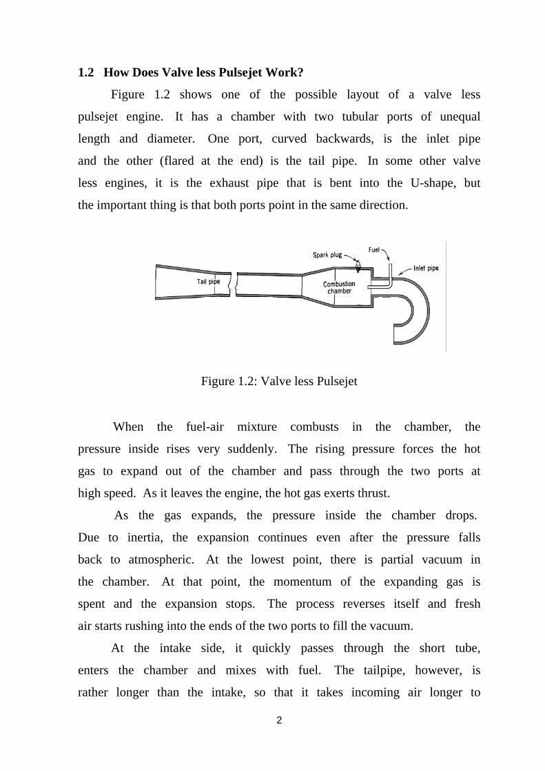
Paul Schmidt and Jean Henri Bertin (among others) tested a
number of designs featuring concave ring baffles in the intake tract,
which offered great resistance to back flow but let fresh air in easily.
A simple version of the Bertin baffle intake is sketched in figure 1.3.
4
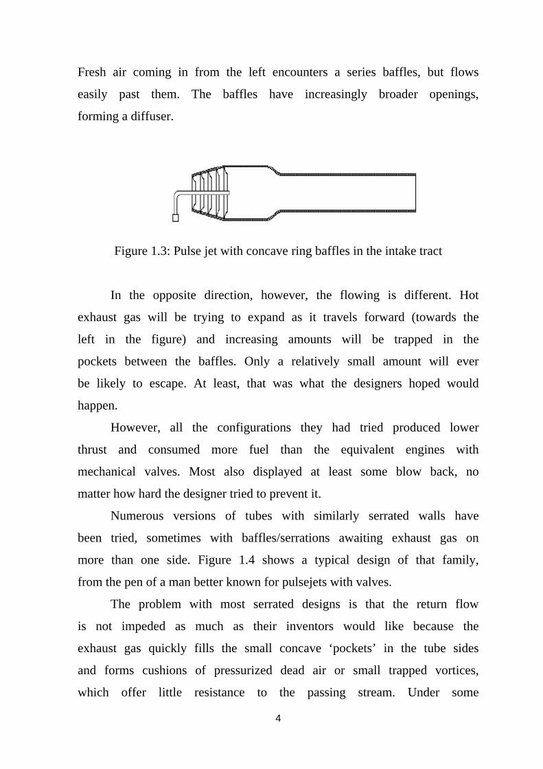
Fresh air coming in from the left encounters a series baffles, but flows
easily past them. The baffles have increasingly broader openings,
forming a diffuser.
Figure 1.3: Pulse jet with concave ring baffles in the intake tract
In the opposite direction, however, the flowing is different. Hot
exhaust gas will be trying to expand as it travels forward (towards the
left in the figure) and increasing amounts will be trapped in the
pockets between the baffles. Only a relatively small amount will ever
be likely to escape. At least, that was what the designers hoped would
happen.
However, all the configurations they had tried produced lower
thrust and consumed more fuel than the equivalent engines with
mechanical valves. Most also displayed at least some blow back, no
matter how hard the designer tried to prevent it.
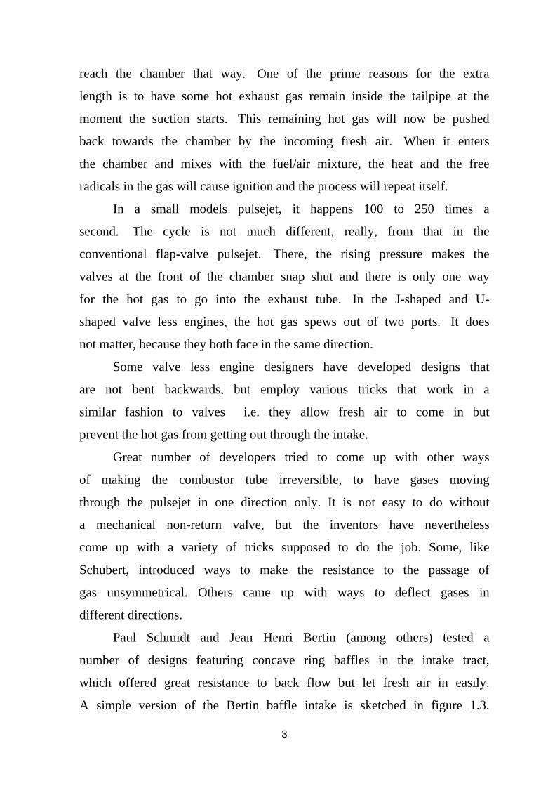
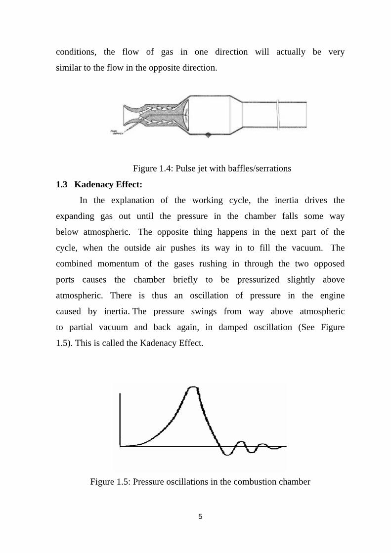
Numerous versions of tubes with similarly serrated walls have
been tried, sometimes with baffles/serrations awaiting exhaust gas on
more than one side. Figure 1.4 shows a typical design of that family,
from the pen of a man better known for pulsejets with valves.
The problem with most serrated designs is that the return flow
is not impeded as much as their inventors would like because the
exhaust gas quickly fills the small concave ‘pockets’ in the tube sides
and forms cushions of pressurized dead air or small trapped vortices,
which offer little resistance to the passing stream. Under some
5
conditions, the flow of gas in one direction will actually be very
similar to the flow in the opposite direction.
Figure 1.4: Pulse jet with baffles/serrations
1.3 Kadenacy Effect:
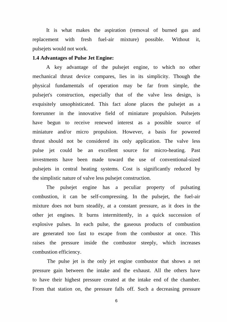
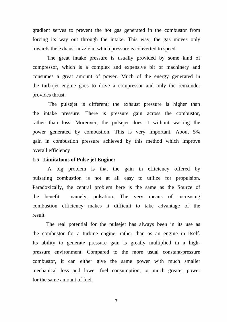
In the explanation of the working cycle, the inertia drives the
expanding gas out until the pressure in the chamber falls some way
below atmospheric. The opposite thing happens in the next part of the
cycle, when the outside air pushes its way in to fill the vacuum. The
combined momentum of the gases rushing in through the two opposed
ports causes the chamber briefly to be pressurized slightly above
atmospheric. There is thus an oscillation of pressure in the engine
caused by inertia. The pressure swings from way above atmospheric
to partial vacuum and back again, in damped oscillation (See Figure
1.5). This is called the Kadenacy Effect.
Figure 1.5: Pressure oscillations in the combustion chamber
6
It is what makes the aspiration (removal of burned gas and
replacement with fresh fuel-air mixture) possible. Without it,
pulsejets would not work.
1.4 Advantages of Pulse Jet Engine:
A key advantage of the pulsejet engine, to which no other
mechanical thrust device compares, lies in its simplicity. Though the
physical fundamentals of operation may be far from simple, the
pulsejet's construction, especially that of the valve less design, is
exquisitely unsophisticated. This fact alone places the pulsejet as a
forerunner in the innovative field of miniature propulsion. Pulsejets
have begun to receive renewed interest as a possible source of
miniature and/or micro propulsion. However, a basis for powered
thrust should not be considered its only application. The valve less
pulse jet could be an excellent source for micro-heating. Past
investments have been made toward the use of conventional-sized
pulsejets in central heating systems. Cost is significantly reduced by
the simplistic nature of valve less pulsejet construction.
The pulsejet engine has a peculiar property of pulsating
combustion, it can be self-compressing. In the pulsejet, the fuel-air
mixture does not burn steadily, at a constant pressure, as it does in the
other jet engines. It burns intermittently, in a quick succession of
explosive pulses. In each pulse, the gaseous products of combustion
are generated too fast to escape from the combustor at once. This
raises the pressure inside the combustor steeply, which increases
combustion efficiency.
The pulse jet is the only jet engine combustor that shows a net
pressure gain between the intake and the exhaust. All the others have
to have their highest pressure created at the intake end of the chamber.
From that station on, the pressure falls off. Such a decreasing pressure
7
gradient serves to prevent the hot gas generated in the combustor from
forcing its way out through the intake. This way, the gas moves only
towards the exhaust nozzle in which pressure is converted to speed.
The great intake pressure is usually provided by some kind of
compressor, which is a complex and expensive bit of machinery and
consumes a great amount of power. Much of the energy generated in
the turbojet engine goes to drive a compressor and only the remainder
provides thrust.
The pulsejet is different; the exhaust pressure is higher than
the intake pressure. There is pressure gain across the combustor,
rather than loss. Moreover, the pulsejet does it without wasting the
power generated by combustion. This is very important. About 5%
gain in combustion pressure achieved by this method which improve
overall efficiency
1.5 Limitations of Pulse jet Engine:
A big problem is that the gain in efficiency offered by
pulsating combustion is not at all easy to utilize for propulsion.
Paradoxically, the central problem here is the same as the Source of
the benefit namely, pulsation. The very means of increasing
combustion efficiency makes it difficult to take advantage of the
result.
The real potential for the pulsejet has always been in its use as
the combustor for a turbine engine, rather than as an engine in itself.
Its ability to generate pressure gain is greatly multiplied in a high-
pressure environment. Compared to the more usual constant-pressure
combustor, it can either give the same power with much smaller
mechanical loss and lower fuel consumption, or much greater power
for the same amount of fuel.

8
Unfortunately, a turbine demands steady flows to function
efficiently. Unsteadiness generates loss. Also, pulsations are
dangerous for the brittle axial turbine blades. Radial turbines are
tougher in that respect, but they are less efficient, especially so with
intermittent flow. They are mostly used to exploit waste heat, as in a
turbocharger, rather than as prime movers. Researchers have toyed
with converting pulsations into a steady flow, but most methods
proved inefficient.
1.6 Objectives of this Project:
Pulse jet engines have recently been recognized as promising
propulsion technology that offers advantage in thermodynamic cycle
efficiency, hardware, simplicity and operation scalability. The
potential for self aspiration operation is highly attractive for the
perspective of efficiency and operation.
One of the main questions in the pulse jet performance analysis
is what the combustion type (mode)? It obviously a strong function of
the cycle frequency and valve timing. A key issue in the conceptional
design and analysis of proposed propulation system is the role of the
combustion mode.
Our objective in this Project to understand based on
thermodynamics the characteristics of the conventional pulse jet
engine then we designed based on the geometrical aspect a pulse jet
engine with 100 lb thrust.

9
CHAPTER TWO
LITERATURE REVIEEW
2.1 Historical Review:
Early attempts to utilize the power obtained from explosions for
propulsion applications date back to late 17th–early 18th centuries and
the contributions of Huygens and Allen are note worthy. In 1729,
Allen proposed a jet propelled ship ‘whose operation is owing to the
explosion of gun powder’ in a proper engine placed within a ship [7].
Before this archival contribution, gun powder was predominantly used
in artillery for destructive purposes.
First exposure of gaseous detonations dates back to 1870–
1883 period when Berthelot and Vieille, and Mallard and Le Chatelier
discovered [7] a combustion mode propagating at a velocity ranging
from 1.5 to 2.5 km/s. This combustion mode arose when gas was
ignited with a high-explosive charge. Later on it was observed in long
tubes even when gas was ignited by non explosive means (spark or
open flame). In this case, flame acceleration along the tube, often
accompanied with flame speed oscillations, was detected prior to
onset of detonation. The most impressive findings of those times
indicated that the detected detonation velocity was independent of the
ignition source and tube diameter and was primarily a function of the
explosive mixture composition. The main distinctive feature of
detonation was a severe mechanical effect implying the development
of a high pressure in the propagating wave. The mechanism of
detonation propagation has been identified as governed by adiabatic
compression of the explosive mixture rather than by molecular
diffusion of heat. During those times, the interest in detonation was
basically associated with explosion prevention in coal mines.

10
A few years later, based on the shock wave theory of Rankine
and Hugoniot, Mikhelson in 1890, Chapman in 1899, and Jouguet in
1904, provided [7] theoretical estimates for the detonation parameters
based on one-dimensional (1D) flow considerations and mass,
momentum and energy conservation laws. In their theory, the
detonation wave was considered as a pressure discontinuity coupled
with the reaction front (instantaneous reaction). According to the
theory, the detonation products possess density that is almost two-fold
higher than the initial mixture density; temperature and pressure that
are, respectively, 10–20% and two-fold higher than the corresponding
values of constant-volume explosion; particle velocity that attains a
value close to one half of the detonation velocity. Comparison of the
theoretical predictions with experimentally observed detonation
velocities showed fairly good agreement.
Since the end of the 19th–the beginning of the 20th century,
significant progress has been made both in experimentation and
analysis of detonations. In addition to explosion safety issues in coal
mines and pits, other applications surfaced, in particular, those dealing
with new technologies, balloon transportation, and reciprocating
internal combustion engines. After the World War I, there was a
considerable growth of interest to combustion in automotive and
aircraft engines.
After World War II, the aviation industry saw a major
advancement in flight capabilities with the development and
implementation of the turbine engine. With this new technology,
aircraft could fly higher, faster, and farther than ever before.
However, along side early turbine development was a different type of
jet power, commonly known today as the pulsejet. The pulsejet
promised lower thrust specific fuel consumption, more robust

11
operating characteristics, and, most importantly, a design that was
significantly simpler mechanically than its turbine counterparts.
However, interest in pulsejets subsided due to poor thrust
performance versus size and horrific decibel performance.
Improvements upon such limitations were never achieved owing
mostly to a lack of fundamental understanding for the pulsejet’s
operation. This, in turn, caused the pulsejet to fade from history’s
timeline and the turbine engine to emerge as the dominant propulsion
option. Today, pulsejet technology shows promise as a viable source
for alternative propulsion purposes, but the general lack of
fundamental understanding remains a foremost inhibiter.
Figure 2.1: A schematic of the Esnaut-Peltr push-pull combustion engine.
Pulsejets operate on a cyclical combustion event, characteristic
of its geometry and fuel. The discovery of the pulsating flame, or
“sensitive flame,” was first noted around 1777 [5]. Conceptual
designs of pulsating combustion devices then followed almost one and
a half centuries later. It was not until the turn of the 20th
century that
the possibility of a cyclical combustion engine was realized and
documented. Two French engineers, Esnault and Peltrie, patented a
design for an engine that drove a turbine wheel. This engine worked
based on the principle of two opposing pulsating combustion columns

12
fitted in a single straight, tubular chamber working out of phase from
one another (Figure 2.1) [5]. Shortly thereafter, another Frenchman
named Georges Marconnet patented a device that was essentially a
variation to the Esnault-Peltrie design. Here, Marconnet replaced the
flap valves with what he termed an “aerodynamic valve.” A simple
area constriction served a similar purpose as the mechanical valve – to
let fuel and air into the combustion chamber but inhibit exhaust gasses
from escaping in the opposite direction. Shown in Figure 2.2,
Marconnet’s engine is, in principle, half of Esnault and Peltrie’s
combustor column without valves.
Figure 2.2: A schematic of the Marconnet valve less pulsejet.
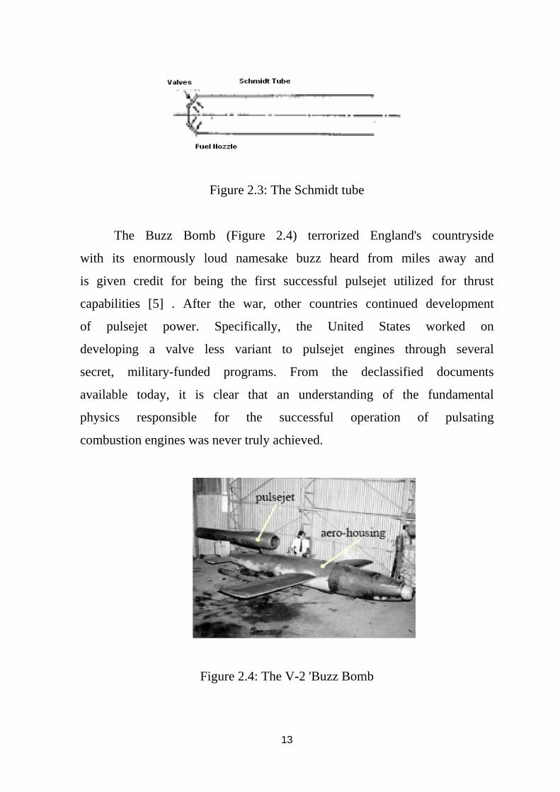
Successful development of an operational pulsating combustion engine
did not come about until the 1930’s when a German named Paul Schmidt [5]
developed and tested the Schmidt tube, or a constant area chamber with
flapper valves at one end and an opening at the other, shown below in Figure
2.3. During World War II, Germany incorporated Schmidt’s design into the
development of their V-1 missile program, or the 'Buzz Bomb,' sister project
to the infamous V-2 rocket. Schmidt's design served as the powerhouse
behind Germany's V-1 weapon.
13
Figure 2.3: The Schmidt tube
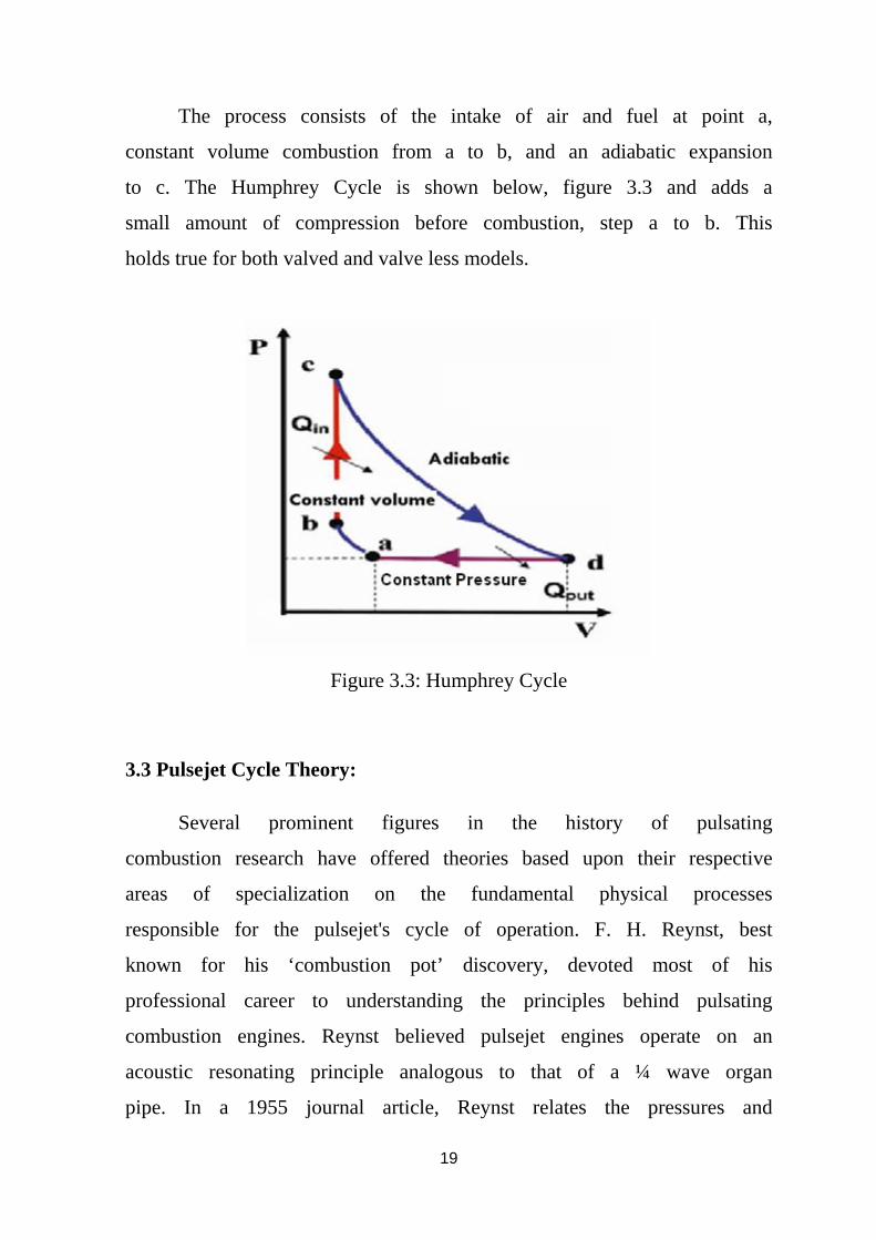
The Buzz Bomb (Figure 2.4) terrorized England's countryside
with its enormously loud namesake buzz heard from miles away and
is given credit for being the first successful pulsejet utilized for thrust
capabilities [5] . After the war, other countries continued development
of pulsejet power. Specifically, the United States worked on
developing a valve less variant to pulsejet engines through several
secret, military-funded programs. From the declassified documents
available today, it is clear that an understanding of the fundamental
physics responsible for the successful operation of pulsating
combustion engines was never truly achieved.
Figure 2.4: The V-2 'Buzz Bomb

14
2.2 Development in Valve less Pulse jet engine:
Valve less pulsejets were not an exclusive American
development. The French company SNECMA (today a child company
to the SAFRAN technology group of Paris, France), for example, was
the first to use a valve less pulsejet for commercial use in powered
flight [5]. The Escopette, illustrated in Figure 2.5, was a valve less
design employed as a backup propulsion source for the French
Emouchet sailplane in the early 1950's. Other foreign interests such as
Russia, China, and Germany were involved in valve less
development, as well. Still, the United States government made
considerable advances in valve less pulsejet technology before
eventually putting the idea to rest until recent years.
Figure 2.5: The French 'Escopette' valveless pulsejet.
Two prominent declassified American collaborations are noted
for valve less pulsejet research in the 1950's to early 60's. Project
Squid, a collaborated effort between the United States Navy and Air
Force to research and develop all potential sources of jet propulsion
available at that time [5], became greatly involved in the investigation
of valveless pulsejets. Under the initial direction of J.G. Logan at the
Cornell Aeronautical Laboratory, Project Squid's valveless pulsejet
work began as an investigation into 'small scale models for
fundamental research purposes and later grew to applications in
helicopter rotor tip propulsion. Logan performed the majority of

15
testing on a valveless design concept conceived from a hobby-scale
valved pulsejet known as the Dynajet. Logan replaced the flapper
valves by a flat plate, completely closing the jet at one end, and
injected fuel and air directly into the combustion chamber. Project
Squid investigated performance characteristics with hydrocarbon fuels
on multiple geometric configurations of the 'Logan' pulsejet,
respectively named after its chief designer. It has been suggested that
the Logan jet improved rate of heat release and cycle efficiency.
The Bureau of Naval Weapons and the Advanced Research
Division of Hiller Aircraft Corporation conducted a cooperative
investigation of valve less pulsejet reactors for the development of
lift-propulsion systems from 1961 to 1963 [5]. Numerous valve less
designs were developed, produced, and tested in the course of the
project. The most well known of these designs was the Hiller-
Lockwood pulsejet illustrated and diagramed below in Figure 2.6. The
Hiller company was successful in several developmental
breakthroughs in pulsejet research, namely decreasing combustor size
with the advent of converging bulkheads at the entrance and exit of
the combustor section. Other accomplishments included the thrust-
efficient design of the Hiller-Lockwood jet, tsfc improvements via
effective thrust augmenters, and scaling studies on a range of size
classes.
In a related concurrent program summarized in a report
presented by Lockwood (1964), the Hiller Aircraft Corporation, under
support from the United States Army Transportation Research
Command (TRECOM), also performed work on conventional valve
less designs resembling that of a Logan jet or the pulsejets utilized in
the valve less work [5]. Investigations into miniature valve less
pulsejets led the Hiller team to develop an engine with a minimum

16
combustion diameter of 0.75 inches, an inlet to combustor area ratio
of 0.34, and an overall length of 12.0 inches. However, poor response
led to a lack of recorded data.
Figure 2.6 Schematic of the Hiller-Lockwood pulsejet

17
CHAPTER THREE
THEORY OF OPERATION
3.1 Unsteady Propulsive Devices:
Pulse detonation engines are characterized by their unsteady
nature (pulse) and detonative combustion (detonation). Axial-flow
engines with unsteady or intermittent combustion are relatively
uncommon. The best known example is the V-1. The power plant of
the V-1, has commonly been referred to as a pulsejet and operates in
the following manner:
1. The combustion chamber is filled with air through a reed type
inlet valve.
Inside the chamber, the air is mixed with fuel and some residual
hot gases.
2. The continued venting of the previous charge sends a
compression wave from the tail into the chamber providing a
slight pre-compression which closes the reed valve. The flow of
the exhaust gases from the previous charge also reverses
direction during this process. The combination of pre-
compression and mixing with hot gases spontaneously ignites
the new charge.
3. Upon ignition, rapid combustion of the reactants increases the
pressure and ejects the products gases out of the tail.
4. The dynamics of the venting causes the inlet pressure to fall
below atmospheric. This opens the reed valve and allows a fresh
charge of air to enter the inlet valve, thus completing the cycle.
A summary of a generic pulse jet engine cycle is shown in figure 3.1.

18
Figure 3.1: Summary of pulse jet engine Cycle
3.2 Pulsejet Cycle:
A pulsejet’s operation can be explained by combining two-
cycles: the Lenoir Cycle which consists of constant pressure
compression followed by constant volume heat addition and then
adiabatic expansion and the Humphrey Cycle, which operates
similarly but has an isentropic compression added to the cycle.
Pulsejets typically have a very small compression ratio that reaches a
maximum at around 1.7. The Lenoir three cycle processes can be seen
below in figure 3.2.
Figure 3.2 Lenoir Cycle
19
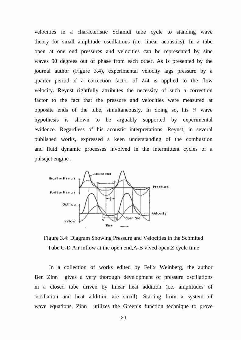
The process consists of the intake of air and fuel at point a,
constant volume combustion from a to b, and an adiabatic expansion
to c. The Humphrey Cycle is shown below, figure 3.3 and adds a
small amount of compression before combustion, step a to b. This
holds true for both valved and valve less models.
Figure 3.3: Humphrey Cycle
3.3 Pulsejet Cycle Theory:
Several prominent figures in the history of pulsating
combustion research have offered theories based upon their respective
areas of specialization on the fundamental physical processes
responsible for the pulsejet's cycle of operation. F. H. Reynst, best
known for his ‘combustion pot’ discovery, devoted most of his
professional career to understanding the principles behind pulsating
combustion engines. Reynst believed pulsejet engines operate on an
acoustic resonating principle analogous to that of a ¼ wave organ
pipe. In a 1955 journal article, Reynst relates the pressures and
20
velocities in a characteristic Schmidt tube cycle to standing wave
theory for small amplitude oscillations (i.e. linear acoustics). In a tube
open at one end pressures and velocities can be represented by sine
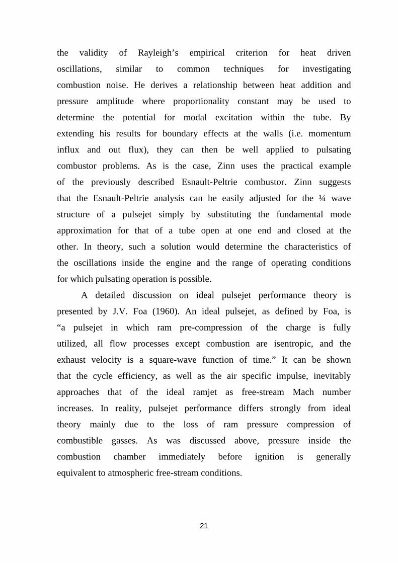
waves 90 degrees out of phase from each other. As is presented by the
journal author (Figure 3.4), experimental velocity lags pressure by a
quarter period if a correction factor of Z/4 is applied to the flow
velocity. Reynst rightfully attributes the necessity of such a correction
factor to the fact that the pressure and velocities were measured at
opposite ends of the tube, simultaneously. In doing so, his ¼ wave
hypothesis is shown to be arguably supported by experimental
evidence. Regardless of his acoustic interpretations, Reynst, in several
published works, expressed a keen understanding of the combustion
and fluid dynamic processes involved in the intermittent cycles of a
pulsejet engine .
Figure 3.4: Diagram Showing Pressure and Velocities in the Schmited
Tube C-D Air inflow at the open end,A-B vlved open,Z cycle time
In a collection of works edited by Felix Weinberg, the author
Ben Zinn gives a very thorough development of pressure oscillations
in a closed tube driven by linear heat addition (i.e. amplitudes of
oscillation and heat addition are small). Starting from a system of
wave equations, Zinn utilizes the Green’s function technique to prove
21
the validity of Rayleigh’s empirical criterion for heat driven
oscillations, similar to common techniques for investigating
combustion noise. He derives a relationship between heat addition and
pressure amplitude where proportionality constant may be used to
determine the potential for modal excitation within the tube. By
extending his results for boundary effects at the walls (i.e. momentum
influx and out flux), they can then be well applied to pulsating
combustor problems. As is the case, Zinn uses the practical example
of the previously described Esnault-Peltrie combustor. Zinn suggests
that the Esnault-Peltrie analysis can be easily adjusted for the ¼ wave
structure of a pulsejet simply by substituting the fundamental mode
approximation for that of a tube open at one end and closed at the
other. In theory, such a solution would determine the characteristics of
the oscillations inside the engine and the range of operating conditions
for which pulsating operation is possible.
A detailed discussion on ideal pulsejet performance theory is
presented by J.V. Foa (1960). An ideal pulsejet, as defined by Foa, is
“a pulsejet in which ram pre-compression of the charge is fully
utilized, all flow processes except combustion are isentropic, and the
exhaust velocity is a square-wave function of time.” It can be shown
that the cycle efficiency, as well as the air specific impulse, inevitably
approaches that of the ideal ramjet as free-stream Mach number
increases. In reality, pulsejet performance differs strongly from ideal
theory mainly due to the loss of ram pressure compression of
combustible gasses. As was discussed above, pressure inside the
combustion chamber immediately before ignition is generally
equivalent to atmospheric free-stream conditions.
22
3.4 Thermodynamic Analysis of Pulsejet Engine:
Let us subscript 0 denote quantities corresponding to the free
atmospheric condition, the subscript 1 denotes stagnation conditions
when the valve are closed, the subscript 2 denotes the condition in the
combustion chamber at the end of the charging process and the
subscript 3 denotes the condition at the end of combustion. Since the
compression from free stream to the stagnation pressure is really the
inverse of isentropic expansion, the chamber condition is now the
stagnation condition, and the exit condition are now the free stream
conditions. Thus we have the equation
(3-1)
The temperature ratio is then:
(3-2)
When the valve is opened, there is a rush of air into the
combustion chamber and the velocity in the throat of the venture must
be very close to the velocity of sound. In other words, the pressure at
the throat is roughly one-half that of . Due to the diffuser shape,
very little of the kinetic energy is recovered as pressure energy. Thus
we can assume that:
(3-3)

23
The temperature , being a representation of the total energy of
the gas at rest, must be the same as , since no appreciable heat loss
can occur.
(3-4)
It will assume that the combustion is carried out at constant
volume. Thus, if the small additional fuel flow is neglected, the heat
added ( ) per unit mass of air is
(3-5)
The prime quantities are referred to the combustion products.
Since the combustion is carried out at constant volume,
(3-6)
Therefore:
(3-7)
To calculate the discharging process, we assume that the
velocity of discharge at every instant is the same as the isentropic
steady expansion from the chamber pressure P to P0, the atmospheric
pressure in the chamber .Due to the removal of mass in the chamber,
the pressure in the chamber will also drop. The expansion of gas in
the chamber is also isentropic if heat loss to the atmosphere is not
counted. This really corresponds to a physical situation of a very large
chamber and a very small discharge nozzle so that the pressure

24
variation in the chamber is very slow and a steady discharge is
approximated. We shall calculate the total impulse due to this charge
process and say that the impulse of such a slow discharge is good
approximation of the actual rapid discharge.
Let be the discharge velocity corresponding to p, then we have
(3-8)
The impulse due to a discharge dm at this velocity is
= (3-9)
If is the mass before the removal of , then the ratio of the
density in the chamber after the removal of dm to that before the
removal is
Similarly the pressure ratio is
Since the process in the combustion chamber is isentropic, we have
Hence by neglecting infinitesimals of high order, we obtain

25
(3-10)
This show that a discharge of will decrease the pressure in the
chamber, as expected. Now where is the volume of the
combustion chamber. Thus we can replace the in equation (3-9)
completely by . The result is
(3-11)
To find the total impulse due to the discharge, we have to
integrate for pressure variations from the initial pressure p3 the
final pressure p0. Therefore
(3-12)
Where . But is the total mass in the combustion
chamber at the beginning of the discharge and is the velocity
of sound a3 corresponding to the condition in the combustion chamber
at the end of combustion. Thus if we call the effective exit velocity Ve
then
d� (3-13)

26
If we have an average mass rate flow of one unit per second,
the average thrust is 1.Ve. This thrust is diminished by the intake
momentum of 1.Vo where Vo is the flight velocity. Thus the actual
thrust for a mass flow of one unit per second is 1. (Ve-Vo). If H is the
heat value of the fuel per lb and the combustion efficiency then the
specific fuel consumption S in lb per hr per lb thrust is
(3-14)
Substituting the value of h from equation (3-7)
(2-15)
(2-16)
Therefore, the specific fuel consumption can easily determined if we
know the pressure ratio and the combustion efficiency
3.5 Frequency of pulsation of pulse jet Engines:
The Frequency in pulse jet engines is directly connected with
the non-steady pulsating flow. In order to have estimate of the
frequency, we shall adopt another simple picture of operation. We
shall assume that explosion pressure ratio to be very nearly
equal to unity. In other words, we shall assume the pressure
amplitudes to be very small and then calculate the frequency by the
elementary considerations to small pressure amplitudes. We then say

27
that the frequency so calculated for very small pressure amplitudes
should be representative of that for large pressure amplitude.
Consider the pulse jet engine as a pipe closed at one end and
open at another. Then the pulsation in the pipe can be considered as a
quarter wave length oscillation with maximum pressure amplitude at
the closed end and zero pressure amplitude but maximum velocity
amplitude at the open end, As shown by figure 3.5. If a* is the velocity
of sound propagation and L the length of the pipe, the frequency of
oscillation is
Cycle per second (2-17)
Figure 3.5: Pressure Distribution at the
Beginning and the End Of combustion
For the application to the pulse jet we must use a*
corresponding to the mean condition of the flow in the duct. Since the
temperature at end of expansion in the duct is
The mean value a* for the velocity of sound is

28
(3-18)
3.6 Thrust of pulse jet Engines:
The average thrust of the pulse jet engine depends on the rate of
air flow and the mixture ratio. The rate at which the air is taken into
the duct per second is, in turn, depended upon the charge per cycle
and the number of the cycle per second. All three factors, however,
are interrelated. For instant, if the cycles per second are very large, the
charge pressure in the chamber will be low, due to the rapid
acceleration necessary to push the air in the chamber. In other words,
the charge per cycle tends to decrease as the frequency were increase.
Furthermore, the combustion process also tends to limit the mixture
ratio that could be effectively used at lower values if the frequency
were increased as the combustion time was shortened. Thus the
average thrust of the engine, being an increasing function of the
product of all these factors, has maximum with respect to the rate of
fuel injection and the frequency, or the length of the tail pipe. The
actual prediction of the thrust of pulse jet is thus rather complicated.
The calculation is based upon empirical data, as the effects of the
volumetric efficiency or breathing capacity and combustion
conditions are very difficult to calculate.
If the ratio of the pressure at the beginning of the combustion to
those at the end of the combustion is maintained and the frequency
and flight mach number kept the same, the thrust of the engine will be
directly proportional to the atmospheric pressure, as everything can
then be referred to the atmospheric pressure, if F’ is the thrust
corresponding to P0’ and F for P0 then under the condition stated

29
(3-19)
Actually the ratio of pressure of the combustion and frequency
depend upon the mixture ratio and atmospheric temperature. The fact
that the atmospheric temperature enters the relation can be seen by the
following reasoning. If the atmospheric temperature is low, the
temperature at the beginning of combustion will also be low, with
everything else the same. Now keeping the mixture ratio and
combustion efficiency the same, the heat due to the combustion per
unit mass of gas and the temperature rise of the gas will be the same,
but the ratio of the absolute temperature and hence the pressure ratio
will be higer due to the lower temperature at the start of the
combustion. This fact tends to give higher thrust at altitudes other
than those calculated from Eq. (3-19). However, the more sluggish
combustion at lower pressure, and hence lower frequencies, may
balance this tendency. Thus, for lack of more accurate information,
Eq. (3-19) can be used to calculate the altitude performance of the
pulsejet, provided the mixture ratios at two altitudes are the same.
The mixture ratio and the frequency are maintained, then the
thrust is directly proportional to the size or the sectional area of the
combustion chamber. Since Eq. (3-17) shows that frequency is a
function of the distance between the air flow valve and the exit of the
duct, this distance must be kept the same for the same frequency.
Actually the change in the flow condition with change in combustion
chamber size will produce a small deviation from this simple rule.
However, it is certain that, with increasing thrust, the pulsejet engine
will become less slender in overall dimensions.

30
To compare the thrust output of pulsejet with other power
plants, it is advantageous to express the net thrust Fnet in terms of a
thrust coefficient defined as
(3-20)
Where A is the combustion chamber cross-sectional area. The
maximum value of the thrust coefficient ( ) which occur at static
condition (V0 = 0). However the coefficient decreases rapidly with the
increase in velocity.

31
CHAPTER FOUR
DESIGN PRINCIPLES
The design of pulse jet must be based upon a wealth of well
performed experiments giving the fundamentals relations between
dimensions, frequency, thrust and mixture ratio.
4.1 Engine Diameter:
One of the texts on pulse jet engine designing was written by
C.E.Tharratt he was staff scientist at the Chrysler Space Division in the
late 1950s.The simple formula that Tharratt proposed to be the core of the
pulse jet design is
(4-1)
Where:
V = Engine Volume (Cubic ft)
L = Effective length (ft)
F =Thrust (lb)
The constant 0.00316 sq ft/ lb is a factor from experimental.
The validity of formula (4-1) has been verified at a wide number of
different pulse jet engines including V1. From this formula when keep the
engine volume (V) constant and increase the effective length (L), then the
power would reduce. In order to do this, the diameter (and cross-section
area) of the engine would need to be reduce. So there is a definite
relationship between cross-sectional area and power.
Also when the length (L) is kept constant and increase the volume
(V) the power would increase; to accomplish this there will be increasing
in the diameter (cross-sectional area) of the engine.

32
Figure 4.1: Engine Dimension
Manipulate equation (4-1) in a simple form
But V= A × L
Where:
A = Area (inches)
Then:
(4-2)
The constant 2.2 is derived from the formula that includes
the engine total volume as a factor.
4.2 Engine Effective Length:
Engine Effective Length does not effect on the output power, but
only effect on the frequency at which the engine will operate. The length
of engine always given as a ratio (L/Dm) which governed by relation:
(4-3)

33
When ( ) the combustion with chemical fuels is difficult to
sustain, from experimental work it found that must not exceed 15.
Table (4.1) show ( ) ratio in Dynajet and V1 engines.
Table 4.1: The ratio (L/Dm) in Dynajet and V1 engines
4.3 Valve Area:
The valve area (Va) for an engine of given size and power is found
using empirical formula as:
Va= 0.23 Mean cross-section area (4-4)
4.4 Valve System:
One of the most critical components of a traditional pulsejet engine
is the intake valve system.
Valves have to open and close several hundred times a second while
being exposed to the thermal stresses associated with being alternately
blasted by searing hot combustion gases and cold incoming air. At the
same time, these thin strips of spring steel must resist metal fatigue and
fracture resulting from the high Mechanical stresses imposed.
Engine
Dynajet 15
V1 9.6
34
It have to do all this while providing a 100 percent seal against
combustion gases when closed, and allowing the smooth, unimpeded flow
of fresh air when open.
To make life even harder, the only power available to open them is
the tiny difference in pressure between the outside air and the small
vacuum created inside the engine by the kadenacy effect of escaping
exhaust gases down the tailpipe.
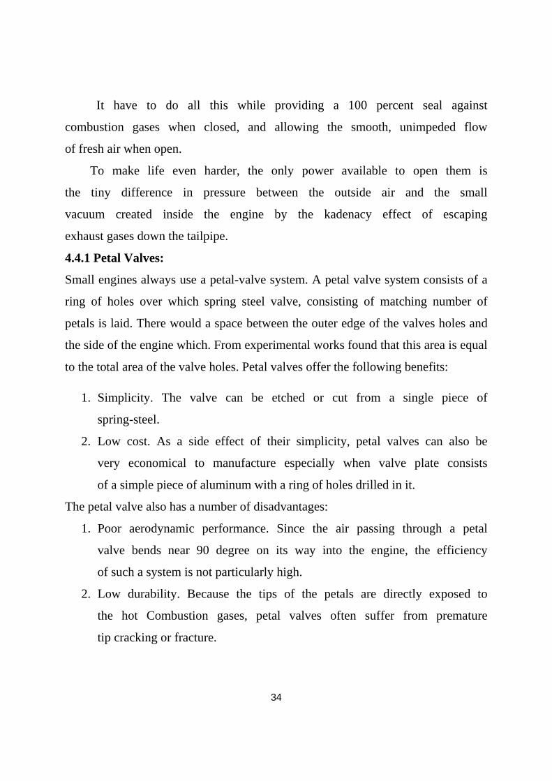
4.4.1 Petal Valves:
Small engines always use a petal-valve system. A petal valve system consists of a
ring of holes over which spring steel valve, consisting of matching number of
petals is laid. There would a space between the outer edge of the valves holes and
the side of the engine which. From experimental works found that this area is equal
to the total area of the valve holes. Petal valves offer the following benefits:
1. Simplicity. The valve can be etched or cut from a single piece of
spring-steel.
2. Low cost. As a side effect of their simplicity, petal valves can also be
very economical to manufacture especially when valve plate consists
of a simple piece of aluminum with a ring of holes drilled in it.
The petal valve also has a number of disadvantages:
1. Poor aerodynamic performance. Since the air passing through a petal
valve bends near 90 degree on its way into the engine, the efficiency
of such a system is not particularly high.
2. Low durability. Because the tips of the petals are directly exposed to
the hot Combustion gases, petal valves often suffer from premature
tip cracking or fracture.

35
3. High maintenance. Since petal valves are usually made as a single
piece, the failure of individual petal requires the replacement of the
entire spring-steel valve.
Figure 4.2: Petal valve
4.4.2 The V or multi-V valve:
Generally use on larger engines, these valves is more efficient than
petal valves because they produce less deflection of the airflow when they
are in an open position.
There are two basic methods of constructing such a valve system
one involves the use of two or more flat metal plates with holes in them,
joined at an angle 45 degrees.
The other method of forming a V valve is the one used in the Argus
V1 where a cast or machined spacer with multiple ribs is used to hold the
valves in position and limit their movement as in figure 4.3.

36
Figure 4.3: V- Valve
V valves provide the following benefits:
1. Higher efficiency than a simple petal valve. Since the incoming air
has a far straighter pathway into the engine, more air is able to flow
for a given size of valve opening when compared to a petal-valve.
2. Lower maintenance costs. Since the individual spring steel valves in
a V-valve system can be replaced as/when they fail, maintaining the
engine becomes a less expensive task and all valves can be used to
the full extent of their lifespan.
3. Scalability. Unlike the petal-valve, a V-valve can be easily scaled to
create the required valve area by simply increasing the length or
number of V-valves in the array.
Of course there are downsides too:
1. Greater complexity. A V-valve generally requires more machining
steps and a higher component count than a petal-valve setup.
2. Increased expense. As a side effect of this complexity, the
production cost for a V-valve system is significantly higher than for

37
a petal-valve. This is another reason why most cheap model engines
don’t use V-valving.
4.5 Combustion Chamber:
Pulse jet engines have much larger diameter section at the front,
from where they funnel down to narrower tail pipe. Most of air / fuel
mixture is burned inside this front section which is called combustion
chamber.
Figure 4.4: Engine combustion chamber
It’s important that the combustion chamber be of a shape and volume that
the rest of the engine is able fill it with a fresh charge of air and fuel during each
operating cycle.
When the combustion chamber is too small then some of the intake charge
will be drawn down into the tailpipe where it may not be burnt as efficiently. Also
when the chamber is too large then it will likely contain too much contaminating
residue from the previous combustion cycle and that can also reduce the efficiency.
A too large combustion chamber will also reduce the magnitude of the vacuum
which draws in the fresh charge of air and that will mean a further power loss.
38
The combustion chamber volume can be found using Schmidt’s
(Designer of V1) empirical results that indicate the following:
”During the intake phase of the pulsejet’s operation it will draw in a
fresh charge of air equal to 15%-20% of the total engine volume”
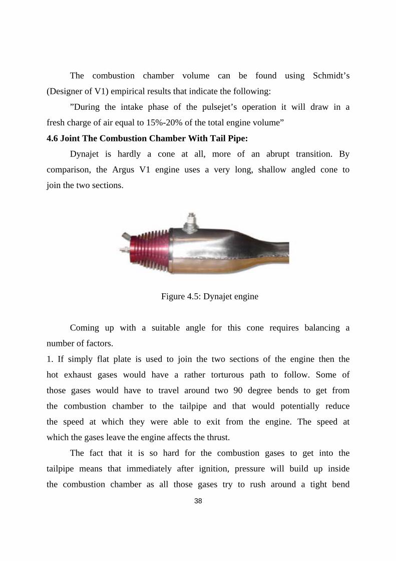
4.6 Joint The Combustion Chamber With Tail Pipe:
Dynajet is hardly a cone at all, more of an abrupt transition. By
comparison, the Argus V1 engine uses a very long, shallow angled cone to
join the two sections.
Figure 4.5: Dynajet engine
Coming up with a suitable angle for this cone requires balancing a
number of factors.
1. If simply flat plate is used to join the two sections of the engine then the
hot exhaust gases would have a rather torturous path to follow. Some of
those gases would have to travel around two 90 degree bends to get from
the combustion chamber to the tailpipe and that would potentially reduce
the speed at which they were able to exit from the engine. The speed at
which the gases leave the engine affects the thrust.
The fact that it is so hard for the combustion gases to get into the
tailpipe means that immediately after ignition, pressure will build up inside
the combustion chamber as all those gases try to rush around a tight bend

39
and down the tailpipe. Those higher pressures can improve combustion
efficiency and actually increase the speed of the gases in the tailpipe.
It’s also worth noting that in the case of a flat plate, the hot gases
that return from the engine's tailpipe and ignite the fresh air-fuel charge
may do so far more efficiently. This is due to an effect that occurs in the
way they form a narrow jet that reaches deep into the chamber rather than
a larger diffuse front that ignites the fuel more slowly.
The faster the fuel burns, the more power our pulsejet will develop
because it will have less time to expand as it burns, thus producing the
higher internal pressures that will, in turn, result in higher tailpipe gas
velocities.
Figure 4.6: Jointing Combustion chamber with tail pipe
Figure (4.7) shows how ignition differs based on the angle of the
cone between combustion chamber and tailpipe. In the second diagram,
the distance between the hot gases and the engine body is far less than in
the first.
The speed at which the combustion flame-front travels through the
fresh air/fuel mixture is relatively slow (just a few tens of feet per second)
in a low-compression engine like the pulsejet. Because of this, the mixture
40
in the second diagram will be burnt far more quickly than that in the first,
since the flame-front will be wider with a much shorter distance to travel.
2. If very long cone that had a shallow taper all the way to the end of the
engine is used to join the two sections of the engine then it would
obviously be much easier for the combustion gases to flow out under
pressure. However, there would also be significantly reducing the ability
of the engine to create a vacuum after combustion is completed because a
much smaller percentage of the exhaust mass would be travelling at
maximum velocity inside the engine.
Force exerted by the escaping gases is equal to their mass times the
velocity to which they are accelerated (F=MA). For a given size of engine,
the mass will always be the same but the velocity to which those gases are
accelerated will depend very much on the design of the tailpipe. There
need plenty of velocity to get the force required to establish a strong
Kadenacy effect.
Tests conducted by the NACA during the 1950s indicated that an
engine designed with just a long convergent cone instead of a straight
tailpipe was very difficult to get running at all.
4.7 Fuel Systems:
One of the great advantages of pulsejet engines is that they can, at
least in theory, be made to run on almost any type of combustible liquid or
gas. Pulsejets aren’t limited to liquid or gas fuels however on at least two
occasions, coal dust has been used as a fuel. It is rumored that the
Germans attempted to run the Argus V1 engine on coal dust when liquid
fuel supplies became almost unobtainable near the end of WW2 and some
of pulsed combustors were designed specifically to use this unusual fuel.

41
There is a report published by Princeton University in 1947 that
summarized a large amount of the research done into pulsejet engines up
to that time. It said “the pulsating jet engine of contemporary design ran on
almost any common fuel with negligible variations in performance.” The
only caveat the report included was that “principal differences were in the
degree of body heating and the rapidity of valve destruction.”
There are two main types of fuel system used in pulsejet engines.
4.7.1 Atomization:
Smaller engines such as the Dynajet have traditionally used a very
crude form of carburetor that using the incoming air to create a spray of
rather coarsely atomized fuel droplets. This atomizing process occurs right
at the front of the engine when the incoming air is forced through a slight
venturi.
The atomizer on small pulsejets uses a venturi to squeeze the
incoming air through a narrowing in the intake. As it squeezes the pressure
drops, although this system does work, the magnitude of the low-pressure
area created in the pulsejet’s venturi is quite small and this means that
there’s not much energy available to suck that fuel through.
Another problem with the simple atomizer is that the fuel droplets
created tend to be very large and therefore do not vaporize particularly.
however, the inside of a pulsejet engine is a very hot place so, despite the
fact that the simple atomizer does a poor job of converting liquid fuel into
a nice fine spray, the high internal temperatures of the engine greatly assist
the conversion of those large droplets of fuel into vapor.

42
Figure 4.7: Simple diagram for atomization
Small pulsejets are extremely sensitive to just where the fuel tank is
placed relative to the atomizer assembly. If the tank too low then the
engine won’t have enough “suck” to pull the fuel up to the atomizer
nozzle. When the tank is too high the gravity will draw the fuel through
effectively flooding the engine.
4.7.2 Injection:
Virtually all engines over 20lbs of thrust use direct fuel injection
rather than atomization. In such a system, the fuel is injected directly into
the engine’s combustion chamber under some form of pressure. This
makes the engine’s operation far more reliable and adds the additional
benefit that by varying the amount of fuel being injected, the engine’s
power can be varied.
There are two ways to inject the fuel, using a fuel pump or
pressurize the entire fuel tank. The simplest injection system for a petal-
valved engine simply involves locating a cross-drilled injection nozzle
directly behind the valve-retainer plate. This nozzle is drilled so that the
incoming fuel is sprayed out directly towards the side of the combustion
chamber. This ensures optimum mixing with the air and (in the case of
liquid fuels) means that any droplets of fuel that aren’t vaporized by the
43
incoming air will be instantly flashed into vapor when they hit the hot
combustion chamber walls.
4.7.3 Timed Injection:
One disadvantage of direct fuel injection is that simple systems such
as the one used in the Argus V1 engine tend to spray fuel throughout the
engine’s operating cycle. Fuel will only burn efficiently when mixed with
exactly the right amount of air. This combustible mixture of air to fuel is
referred to as the “stoichiometric ratio” and it varies depending on the type
of fuel being used. Using timed fuel injection would be a way to improve
the fuel-efficiency of pulsejet engines.
The pressure inside the engine falls to below 1 atmosphere during
the intake phase and rises to as much as twice atmospheric during
combustion and exhaust phases. A valve placed over the fuel jet is
sufficient to provide a degree of injection timing and the addition of this
mechanism can provide a noticeable improvement in the fuel-efficiency of
a large pulsejet.

44
CHAPTER FIVE
RESULTS AND RECOMMENDATIONS
In this study we consider a conceptional design of pulse jet engine with a
thrust 100 lb, the goal of present study is to estimate in very simple fashion
the dimensions of pulse jet engine. We have not considered important
aspects such as inlet diffuser and exhaust nozzles effects. All these factors
will be significant in real applications.
1-Engine Diameter:
from equation (4-2), using the amount of thrust of the engine, the mean cross-
sectional area:
100 = 2.2 A
A= 45.45 sq in
The mean diameter of the engine
Dm =
= 7.61 in
2- Engine Length:
Using relation (4-3), assume ( ) = 12, then engine length can be
calculated:
= 12 then the effective length
L = 12 Dm
= 12 7.61
= 91.32 in

45
3- Total Petal Valve Area:
From relation (4-4), total valve area:
= 0.23 45.45
= 10.45 sq in
Relation (4-4 ) assume that the intake is an open hole, with no loss due to
the presence of valves, but when there is valves there will be losses, petal
valves have Poor aerodynamic performance. Assume that the efficiency of
intake valves is 50%, then the actual area (Vactual) of valves required
Vactual=
=
= 20.91 sq in
4- Petal Valve:
Increase the size of hole would increase the pressure on the valves
themselves which cause them to bend so that it begins to dish into the
holes which affects their operation. Assume using valve with 12 hole, then
hole area will be:
Ah =
=
= 1.74 sq in
Then each hole diameter (Dh) will be:
Dh =
= 1.49 in

46
5- Combustion Chamber Diameter:
Petal valve holes will place in a ring around the edge of the pipe, so there
is need of a certain amount of space between the holes .
Figure 5.1: Petal valve front view
Assume there is ¼ inch gap between the holes, then the total
circumference of the circle drawn through the center of each hole will be
= Number of holes Diameter + Number of Gaps Grip size
= 12 1.49 + 11 .25
= 20.63 in
Diameter of the Circle which runs through the center of each hole
D =
= 6.07 inches
The diameter of the circle which runs around the outer edge of the ring of
holes:
D0 = 6.566 +1.49
= 8.06 inches

47
There would be a 20.907 square inches of space around the ring of holes,
then the overall combustion chamber area will be
AO=
=71.89 square inches
Then the combustion chamber diameter
DC=
=9.57 inches
6- Combustion chamber length:
Using Schmidt’s empirical results in chapter four (4.5), then the engine
will suck in a volume of air equal to:
Vair= 91.32
=830.72 cubic inches
Combustion chamber length will be:
CL=
= 13.683 inches
7- Joint The Combustion Chamber With Tail Pipe:
Using an angle of 30 degrees for the section between the combustion
chamber and the tailpipe. This will provide some post combustion
confinement to increase the internal operating pressures while ensuring
that the engine still has good internal mass-flow speeds to provide
maximum Kadenacy effect.

48
Figure 5.2: Joint combustion chamber with tail pipe using 300 cone
From the figure above, the length of joint (Lc) will be
Lc = 1.69 inches
Recommendations:
While this study present very much through investigation on the geometrical
design of pulse jet engine, continued work is needed on designing fuel and ignition
systems.
For more study of engine, the design need to be built using suitable material
and tested in lab to compare the actual thrust with the theoretical, study the effect
of changing dimensions on engine performance. Combustion chamber volume and
shape, valve system type as well as, the inclination of the transition section have
ability to improve engine performance.
49
REFERENCES
[1] Bruce Simpson, The Enthusiast’s Guide to Pulse Jet Engine,
http://aardvark.co.nz/pjet, 2004.
[2] Eric Winter Berger, Application of Steady and Unsteady Detonation
Waves To Propulsion, California Institute for Technology,2004
[3] Adam Paul Kiker, Experimental Investigations of Mini-Pulse Jet
Engines, North Carolina State University, 2005.
[4] Michael Alexander Schoer, Experimental Investigations in 15
Centimeters Class Pulse Jet Engines, North Carolina State University,
2005.
[5] Robert Lewis Ordon, Experimental Investigations into the Operational
Parameter of a 50 Centimeters Class Pulse Jet Engine, North Carolina
State University, 2006.
[6] Staff of the Jet Propulsion Laboratory, Jet Propulsion, California
Institute for Technology, 1946.
[7] G.D.ROY, Pulse Detonation Propulsion : Challenges, Current Status and
Future Perspective, http://www.elsevier.com/locate/pecs , 2004.
[8] T.W.Chao,E.Winterberger, J.E.Shapherd, On the Design of Pulse
Detonation Engines, California Institute for Technology,2001
[9] Fredrik Westberg, Inside The Pulse Jet Engine,
http://www.geocities.com