theoretical and experimental sonochemistry involving...
TRANSCRIPT
Theoretical and Experimental SonochemistryInvolving Inorganic Systems

.
Pankaj � Muthupandian AshokkumarEditors
Theoretical and ExperimentalSonochemistry InvolvingInorganic Systems
EditorsProf. PankajDepartment of ChemistryFaculty of ScienceDayalbagh Educational InstituteAgra 282 110 Uttar [email protected];[email protected]
Prof. Muthupandian AshokkumarUniversity of MelbourneSchool of Chemistry3010 Parkville [email protected]
ISBN 978-90-481-3886-9 e-ISBN 978-90-481-3887-6DOI 10.1007/978-90-481-3887-6Springer Dordrecht Heidelberg London New York
Library of Congress Control Number: 2010937992
# Springer Science+Business Media B.V. 2011No part of this work may be reproduced, stored in a retrieval system, or transmitted in any form or by anymeans, electronic, mechanical, photocopying, microfilming, recording or otherwise, without writtenpermission from the Publisher, with the exception of any material supplied specifically for the purposeof being entered and executed on a computer system, for exclusive use by the purchaser of the work.
Cover design: WMXDesign GmbH
Printed on acid-free paper
Springer is part of Springer Science+Business Media (www.springer.com)
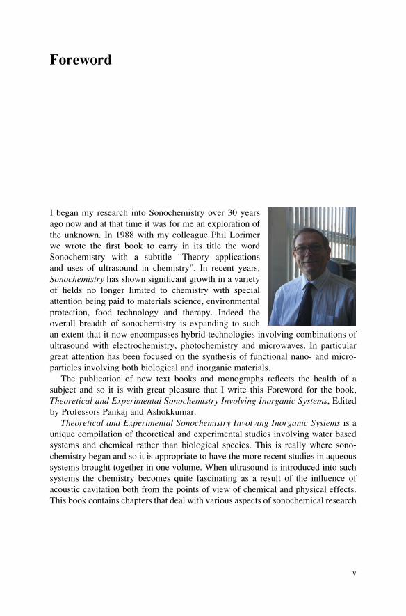
Foreword
I began my research into Sonochemistry over 30 years
ago now and at that time it was for me an exploration of
the unknown. In 1988 with my colleague Phil Lorimer
we wrote the first book to carry in its title the word
Sonochemistry with a subtitle “Theory applications
and uses of ultrasound in chemistry”. In recent years,
Sonochemistry has shown significant growth in a variety
of fields no longer limited to chemistry with special
attention being paid to materials science, environmental
protection, food technology and therapy. Indeed the
overall breadth of sonochemistry is expanding to such
an extent that it now encompasses hybrid technologies involving combinations of
ultrasound with electrochemistry, photochemistry and microwaves. In particular
great attention has been focused on the synthesis of functional nano- and micro-
particles involving both biological and inorganic materials.
The publication of new text books and monographs reflects the health of a
subject and so it is with great pleasure that I write this Foreword for the book,
Theoretical and Experimental Sonochemistry Involving Inorganic Systems, Editedby Professors Pankaj and Ashokkumar.
Theoretical and Experimental Sonochemistry Involving Inorganic Systems is aunique compilation of theoretical and experimental studies involving water based
systems and chemical rather than biological species. This is really where sono-
chemistry began and so it is appropriate to have the more recent studies in aqueous
systems brought together in one volume. When ultrasound is introduced into such
systems the chemistry becomes quite fascinating as a result of the influence of
acoustic cavitation both from the points of view of chemical and physical effects.
This book contains chapters that deal with various aspects of sonochemical research
v
in aqueous solutions with a particular emphasis on inorganic systems. This will be
an important text for all those interested in or directly involved with current
sonochemistry research.
September 2010 Timothy J. Mason
Professor of Chemistry
Coventry University, UK
vi Foreword
Preface
The themes of several books published in the field of sonochemistry revolve around
physical and chemical aspects involving mainly organic chemistry or a combina-
tion of physics, chemistry and other areas. The sonochemical studies involving
inorganic reactions, although numerous, are scarcely discussed and compiled in the
existing literature. This prompted us to editing this book. This was welcomed and
has been made successful by many contributors, as can be seen through various
chapters of this book. Besides, the availability of a book devoted to inorganic
systems in sonochemistry may also help undergraduate students, juvenile workers
and senior researchers alike to learn about sonochemistry and publicize the sono-
chemistry research field to a much broader community.
The book offers a theoretical introduction in the first three chapters, provides
recent applications in material science in the next four chapters, describes the
effects of ultrasound in aqueous solutions in the following five chapters and finally
discusses the most exciting phenomenon of sonoluminescence in aqueous solutions
containing inorganic materials in subsequent two chapters, before ending with a
few basic introductory experiments of sonochemistry and sonoluminescence in the
concluding chapter.
Prof. Yasui discussed the fundamentals of acoustic cavitation and sonochemistry
through the splitting of water to generate free radicals as a consequence of excep-
tionally high temperatures, pressures and mass flow conditions generated during
acoustic cavitation in solutions. Dr. Gogate has discussed the design aspects of
cavitation reactors and examined the effect of intensity and frequency of ultra-
sound, geometry of the reactor, physicochemical properties of liquids and the
operational temperature on the intensity of cavitation for the maximization of
process efficiencies. Later, Dr. Gogate and Prof. Pandit have described the phe-
nomenon of hydrodynamic cavitation for the scale up operation of several physical,
chemical and biological processes. Prof. Garcia has discussed the combined effects
of electrochemistry and ultrasound for the production of gas, metal deposits and
metal oxides, in addition to providing a summary of the fundamental aspects,
experimental set-up and different applications of a rather new field of applied
vii
sonoelectrochemistry. Prof. Okitsu has illustrated the synthesis of metal nanopar-
ticles and the effects of dissolved gases, rate of reduction and the concentration of
organic additives on the size and shapes of nanoparticles. To advance the portrayal
further, Assistant Prof. Anandan and Prof. Ashokkumar have provided additional
information on the sonochemical preparation of monometallic, bimetallic and metal
loaded semiconductor nanoparticles. In continuation with these reviews, Associate
Prof. Sonawane and Dr. Kulkarni have described the sonochemical synthesis of
nanocalcium carbonate through the acoustic and hydrodynamic cavitations. Asso-
ciate Prof. Sivakumar has summarized various kinds of simple and mixed oxides
and sulphides obtained in the last few years through sonochemical processes. Prof.
Pankaj has discussed the effect of ultrasound propagation in aqueous solutions in
the atmospheres of inert and reactive gases and the precipitation behavior of
hydroxides of several di- and tri-valent metal ions, besides reporting the results of
nephelometric and conductometric studies of sonicated solutions of these metal
ions. Prof. Pankaj and Dr. Chauhan further reported the redox characteristics of
ferrous and ferric ions in aqueous solutions and a comparative account of the
oxidizing power of permanganate and dichromate ions, under the influence of
ultrasound. In the next two chapters, Mr Verma and Prof. Pankaj have advanced
the description of sonophotocatalytic degradation of phenol and several amines and
also found a very interesting improvement of such degradation in the presence of
rare earth ions, co-added with the photocatalyst, titanium dioxide. Other conven-
tional methods for the degradation of these species in aqueous solutions have been
compared with the sonochemical treatment processes. To explain a relatively
difficult but equally fascinating consequence of high intensity ultrasound, Prof.
Choi has discussed the phenomenon of sonoluminescence from aqueous solutions
containing inorganic ions, especially alkali metal atom emission in aqueous solu-
tions in various environments and described the emission mechanism, supporting
the gas phase origin of the emission. Finally, Dr. Brotchie, Prof. Grieser and Prof.
Ashokkumar have discussed the role of salts in acoustic cavitation and the use of
inorganic complexes as cavitation probes to infer invaluable quantitative informa-
tion regarding the temperature and pressure at the time of cavitation bubble
collapse. Few basic experiments of sonochemistry and sonoluminescence have
also been described in the last segment of the book.
Besides the contributors of various chapters, we also wish to acknowledge the
support and critical evaluation of the chapters by several professionals (cannot be
named due to confidentiality) who reviewed the articles in a timely manner.
We sincerely hope that this book is immensely beneficial to graduate students and
researchers to learn the fundamental aspects of cavitation and to launch new research
activities in the sonochemistry research field. The readers will also realize that
sonochemistry is not just limited to “chemistry” but has the potential to incorporate
in other areas including physics, engineering, biochemistry and medicine.
Agra, India Pankaj
Melbourne, Australia Muthupandian Ashokkumar
June 2010
viii Preface
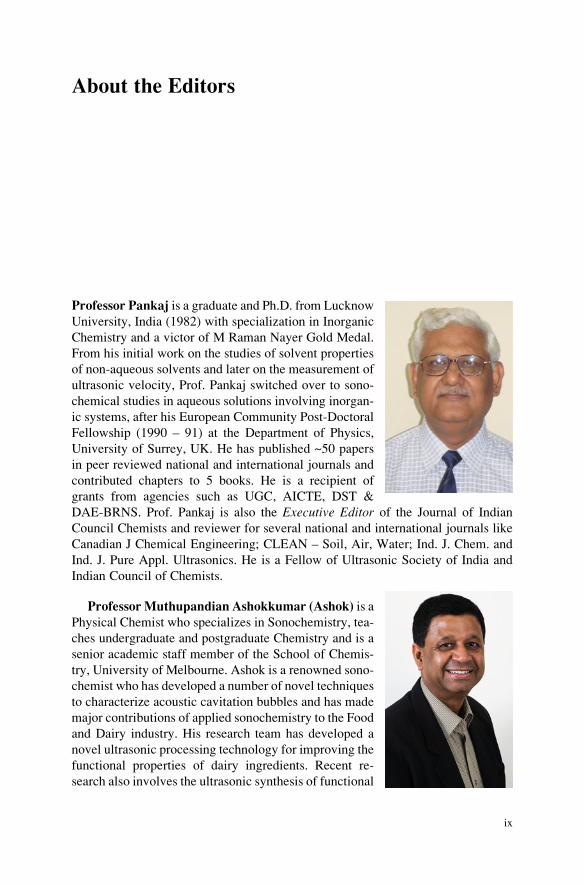
About the Editors
Professor Pankaj is a graduate and Ph.D. from Lucknow
University, India (1982) with specialization in Inorganic
Chemistry and a victor of M Raman Nayer Gold Medal.
From his initial work on the studies of solvent properties
of non-aqueous solvents and later on the measurement of
ultrasonic velocity, Prof. Pankaj switched over to sono-
chemical studies in aqueous solutions involving inorgan-
ic systems, after his European Community Post-Doctoral
Fellowship (1990 – 91) at the Department of Physics,
University of Surrey, UK. He has published ~50 papers
in peer reviewed national and international journals and
contributed chapters to 5 books. He is a recipient of
grants from agencies such as UGC, AICTE, DST &
DAE-BRNS. Prof. Pankaj is also the Executive Editor of the Journal of Indian
Council Chemists and reviewer for several national and international journals like
Canadian J Chemical Engineering; CLEAN – Soil, Air, Water; Ind. J. Chem. and
Ind. J. Pure Appl. Ultrasonics. He is a Fellow of Ultrasonic Society of India and
Indian Council of Chemists.
ProfessorMuthupandian Ashokkumar (Ashok) is a
Physical Chemist who specializes in Sonochemistry, tea-
ches undergraduate and postgraduate Chemistry and is a
senior academic staff member of the School of Chemis-
try, University of Melbourne. Ashok is a renowned sono-
chemist who has developed a number of novel techniques
to characterize acoustic cavitation bubbles and has made
major contributions of applied sonochemistry to the Food
and Dairy industry. His research team has developed a
novel ultrasonic processing technology for improving the
functional properties of dairy ingredients. Recent re-
search also involves the ultrasonic synthesis of functional
ix
nano- and biomaterials including protein microspheres that can be used in diagnos-
tic and therapeutic medicine. He is an Editorial Board Member of UltrasonicsSonochemistry, an international journal devoted to sonochemistry research. He has
edited/co-edited several books and special issues for journals; published ~200
refereed papers in high impact international journals and books; and delivered
over 100 invited/keynote/plenary lectures at international conferences and academ-
ic institutions. Ashok is the recipient of several prizes, awards and fellowships,
including the Grimwade Prize in Industrial Chemistry. He is a Fellow of the Royal
Australian Chemical Institute.
x About the Editors
Acknowledgement
Prof. Ram Gopal, my Ph.D. supervisor had rightly said about 30 years back that
science could not be pursued lifelong unless enjoyed, without me realizing that it
is eventually coming to happen in my life too. Towards the end of my Ph.D.
work, in early eighties, I read about ultrasound – a word which fascinated me and
I drifted towards measuring ultrasonic velocity in non-aqueous solvents of high
dielectric constant and their solutions, interpreting their variations in terms of
thermodynamic parameters. But the real contact with sonochemistry was through
Prof. R.C. Chivers, my supervisor for European Community Post Doctoral fellow-
ship at the University of Surrey, UK, who fixed my appointment with Prof. T.J.
Mason in early nineties, when sonochemistry was still in its infancy. However,
limitations of finance, space and culture of working in an apprehensive small Indian
University later was always only an impediment but, of course, never a barrier to my
motivation. The initial sonochemical results of my students, different from conven-
tional chemical reactions of aqueous wet chemistry always stimulated me to stick to
this field.
The idea of writing a book on inorganic sonochemistry originated way back in
2000 but turned to reality only recently when discussed with Dr. Sonia Ojo from
Springer UK. She thankfully introduced me to Prof. Muthupandian Ashokkumar,
University of Melbourne, Australia, a very well known name in the area of
sonochemistry and sonoluminescence, to accomplish the task. Furthermore,
I would also like to acknowledge Mrs. Claudia Culierat from Springer UK for
her instantaneous and supportive attention to all my queries related to editorial
assistance.
With all humility, I acknowledge the initial strength derived for this book from
Dr. Ashok Kumar, Head, Ultrasonics Division, National Physical Laboratory, New
Delhi, besides the unwavering encouragement from Dr. G.C. Saxena, Ex VC,
Awadh University, Faizabad and Dr. BR Ambedkar University, Agra and Prof. P.
Muruthamuthu, Ex VC Madurai Kamraj University, Dr. G.N. Pandey, BRNS and
Dr. A.K. Tripathi, BARC.
xi
I cannot close the eyes to admit a very patient, silent and supportive co-operation
of my compassionate wife, Dr. Hemlata Srivastava and two considerate sons,
Abhijit Srivastav and Arpit Srivastava, who suffered seclusion and neglect due to
my invariable involvement with the book for about 1 year. Last, but not the least my
gratitude to all my friends and well wishers, who through their admiration or
criticism added directly or indirectly to my strength and inspired vigorously to
complete the task in the form as it is today.
Agra, India Prof. Pankaj
June 2010
xii Acknowledgement
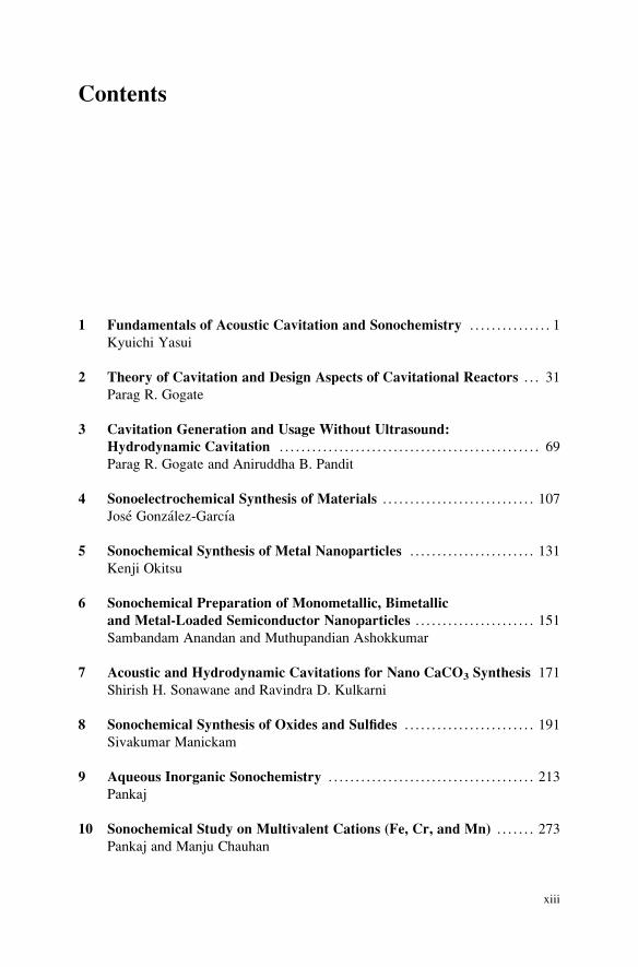
Contents
1 Fundamentals of Acoustic Cavitation and Sonochemistry . . . . . . . . . . . . . . . 1
Kyuichi Yasui
2 Theory of Cavitation and Design Aspects of Cavitational Reactors . . . 31
Parag R. Gogate
3 Cavitation Generation and Usage Without Ultrasound:
Hydrodynamic Cavitation . . . . . . . . . . . . . . . . . . . . . . . . . . . . . . . . . . . . . . . . . . . . . . . . 69
Parag R. Gogate and Aniruddha B. Pandit
4 Sonoelectrochemical Synthesis of Materials . . . . . . . . . . . . . . . . . . . . . . . . . . . . 107
Jose Gonzalez-Garcıa
5 Sonochemical Synthesis of Metal Nanoparticles . . . . . . . . . . . . . . . . . . . . . . . 131
Kenji Okitsu
6 Sonochemical Preparation of Monometallic, Bimetallic
and Metal-Loaded Semiconductor Nanoparticles . . . . . . . . . . . . . . . . . . . . . . 151
Sambandam Anandan and Muthupandian Ashokkumar
7 Acoustic and Hydrodynamic Cavitations for Nano CaCO3 Synthesis 171
Shirish H. Sonawane and Ravindra D. Kulkarni
8 Sonochemical Synthesis of Oxides and Sulfides . . . . . . . . . . . . . . . . . . . . . . . . 191
Sivakumar Manickam
9 Aqueous Inorganic Sonochemistry . . . . . . . . . . . . . . . . . . . . . . . . . . . . . . . . . . . . . . 213
Pankaj
10 Sonochemical Study on Multivalent Cations (Fe, Cr, and Mn) . . . . . . . 273
Pankaj and Manju Chauhan
xiii
11 Sonochemical Degradation of Phenol in the Presence of Inorganic
Catalytic Materials . . . . . . . . . . . . . . . . . . . . . . . . . . . . . . . . . . . . . . . . . . . . . . . . . . . . . . . 287
Pankaj and Mayank Verma
12 Sonophotocatalytic Degradation of Amines in Water . . . . . . . . . . . . . . . . . 315
Mayank Verma and Pankaj
13 Sonoluminescence of Inorganic Ions in Aqueous Solutions . . . . . . . . . . . 337
Pak-Kon Choi
14 The Role of Salts in Acoustic Cavitation and the Use of Inorganic
Complexes as Cavitation Probes . . . . . . . . . . . . . . . . . . . . . . . . . . . . . . . . . . . . . . . . 357
Adam Brotchie, Franz Grieser and Muthupandian Ashokkumar
15 Introductory Experiments in Sonochemistry
and Sonoluminescence . . . . . . . . . . . . . . . . . . . . . . . . . . . . . . . . . . . . . . . . . . . . . . . . . . . . 381
Pankaj, Mayank Verma, Shikha Goyal and Adam Brotchie
Index . . . . . . . . . . . . . . . . . . . . . . . . . . . . . . . . . . . . . . . . . . . . . . . . . . . . . . . . . . . . . . . . . . . . . . . . . . . . 395
xiv Contents
Chapter 1
Fundamentals of Acoustic Cavitation
and Sonochemistry
Kyuichi Yasui
Abstract Acoustic cavitation is the formation and collapse of bubbles in liquid
irradiated by intense ultrasound. The speed of the bubble collapse sometimes
reaches the sound velocity in the liquid. Accordingly, the bubble collapse becomes
a quasi-adiabatic process. The temperature and pressure inside a bubble increase to
thousands of Kelvin and thousands of bars, respectively. As a result, water vapor
and oxygen, if present, are dissociated inside a bubble and oxidants such as OH, O,
and H2O2 are produced, which is called sonochemical reactions. The pulsation of
active bubbles is intrinsically nonlinear. In the present review, fundamentals of
acoustic cavitation, sonochemistry, and acoustic fields in sonochemical reactors
have been discussed.
1.1 Introduction
An acoustic wave (sound) is a propagation of pressure oscillation in medium such
as air or liquid water with the sound velocity [1]. Ultrasound is inaudible sound
and its frequency of pressure oscillation is above 20 kHz (20,000 oscillations per
second) [2]. For convenience, an acoustic wave above 10 kHz in frequency is
sometimes called an ultrasonic wave.
When the pressure amplitude of an acoustic wave in liquid or solid exceeds the
ambient pressure (atmospheric pressure), the instantaneous pressure becomes neg-ative during the rarefaction phase of an acoustic wave. Negative pressure is definedas the force acting on the surface of a liquid (or solid) element per surface area to
expand the element [3, 4]. For example, consider a closed cylinder filled with liquid
K. Yasui (*)
National Institute of Advanced Industrial Science and Technology (AIST), 2266-98 Anagahora,
Shimoshidami, Moriyama-ku, Nagoya 463-8560, Japan
e-mail: [email protected]
Pankaj and M. Ashokkumar (eds.), Theoretical and ExperimentalSonochemistry Involving Inorganic Systems, DOI 10.1007/978-90-481-3887-6_1,# Springer ScienceþBusiness Media B.V. 2011
1
with a movable piston. When a piston is pulled strongly, the liquid volume slightly
increases. At this moment, the pressure in the liquid is negative. Negative pressureis possible only in liquid or solid.
When the instantaneous local pressure becomes negative in liquid irradiated by
ultrasound, bubbles are generated because gas such as air dissolved in the liquid can
no longer be dissolved in the liquid under negative pressure, which is called
acoustic cavitation [5, 6]. For a static condition, vapor bubbles are generated
when the static pressure is lower than the saturated vapor pressure, which is called
boiling. In many cases of acoustic cavitation, the instantaneous local pressure
should be negative because the duration of low pressure is short.
The difference between acoustic cavitation and boiling is the collapse of bubbles
in acoustic cavitation. Under ultrasound, a generated bubble expands during the
rarefaction phase and collapses during the compression phase. The speed of the
bubble collapse increases to the sound velocity in liquid. Accordingly, the bubble
collapse is a quasi-adiabatic process where “quasi” means that considerable thermal
conduction takes place between the interior of a bubble and the surrounding liquid.
The temperature and pressure inside a bubble increase to thousands of Kelvin and
thousands of bars, respectively at the end of the bubble collapse [7]. Furthermore, a
bubble emits a shock wave into the surrounding liquid just after the end of the
bubble collapse [8-11]. This bubble collapse is absent in boiling.
As the temperature and pressure dramatically increase inside a bubble at the end
of the collapse, water vapor and oxygen, if present, are dissociated inside a bubble
and oxidants such as OH, O, and H2O2 are created [12, 13]. They dissolve into the
liquid and solutes are oxidized by them. This is called sonochemical reaction. For
example, potassium iodide (KI) in aqueous solution is oxidized by the irradiation of
ultrasound ((1.1)), and the solution is gradually colored by the product (I3-) as the
irradiation time increases.
3I� þ 2OH ! I�3 þ 2OH� (1.1)
1.2 Acoustic Cavitation
1.2.1 Transient and Stable Cavitation
There are two types in acoustic cavitation. One is transient cavitation and the other
is stable cavitation [14, 15]. There are two definitions in transient cavitation. One is
that the lifetime of a bubble is relatively short such as one or a few acoustic cycles
as a bubble is fragmented into daughter bubbles due to its shape instability. The
other is that bubbles are active in light emission (sonoluminescence (SL)) or
chemical reactions (sonochemical reactions). Accordingly, there are two definitions
in stable cavitation. One is that bubbles are shape stable and have a long lifetime.
The other is that bubbles are inactive in SL and chemical reactions. There exist
2 K. Yasui
some bubbles which are both shape stable and active in SL or chemical reactions.
They are classified into stable cavitation bubbles by the former definition and called
“high-energy stable cavitation” bubbles. On the other hand, they are classified into
transient cavitation bubbles by the latter definition and called “repetitive transient
cavitation” bubbles. Whenever the terms transient and stable cavitation are used, it
is necessary to indicate which definition is used, shape stability or activity.
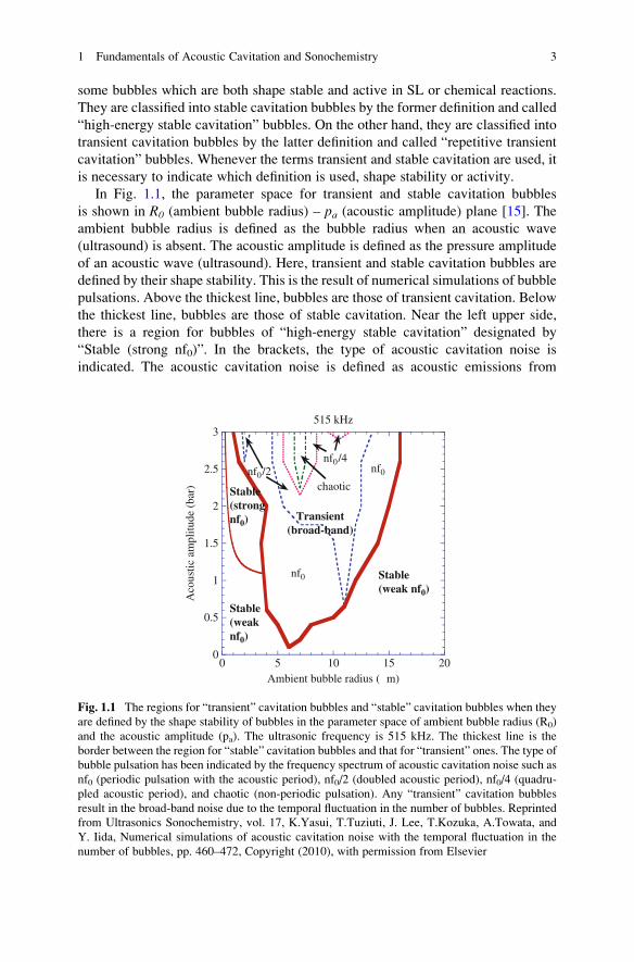
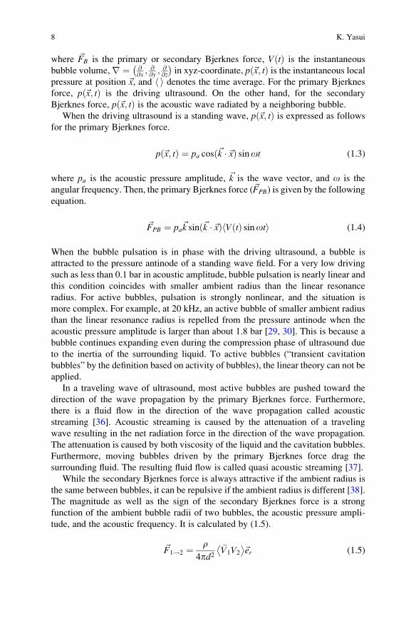
In Fig. 1.1, the parameter space for transient and stable cavitation bubbles
is shown in R0 (ambient bubble radius) – pa (acoustic amplitude) plane [15]. The
ambient bubble radius is defined as the bubble radius when an acoustic wave
(ultrasound) is absent. The acoustic amplitude is defined as the pressure amplitude
of an acoustic wave (ultrasound). Here, transient and stable cavitation bubbles are
defined by their shape stability. This is the result of numerical simulations of bubble
pulsations. Above the thickest line, bubbles are those of transient cavitation. Below
the thickest line, bubbles are those of stable cavitation. Near the left upper side,
there is a region for bubbles of “high-energy stable cavitation” designated by
“Stable (strong nf0)”. In the brackets, the type of acoustic cavitation noise is
indicated. The acoustic cavitation noise is defined as acoustic emissions from
0
0.5
1
1.5
2
2.5
3
0
515 kHz
Aco
ustic
am
plitu
de (
bar)
Ambient bubble radius (µm)
Transient(broad-band)
Stable(weak nf0)
Stable(weaknf0)
Stable(strongnf0)
nf0/4nf0
nf0
nf0/2chaotic
5 10 15 20
Fig. 1.1 The regions for “transient” cavitation bubbles and “stable” cavitation bubbles when they
are defined by the shape stability of bubbles in the parameter space of ambient bubble radius (R0)
and the acoustic amplitude (pa). The ultrasonic frequency is 515 kHz. The thickest line is the
border between the region for “stable” cavitation bubbles and that for “transient” ones. The type of
bubble pulsation has been indicated by the frequency spectrum of acoustic cavitation noise such as
nf0 (periodic pulsation with the acoustic period), nf0/2 (doubled acoustic period), nf0/4 (quadru-
pled acoustic period), and chaotic (non-periodic pulsation). Any “transient” cavitation bubbles
result in the broad-band noise due to the temporal fluctuation in the number of bubbles. Reprinted
from Ultrasonics Sonochemistry, vol. 17, K.Yasui, T.Tuziuti, J. Lee, T.Kozuka, A.Towata, and
Y. Iida, Numerical simulations of acoustic cavitation noise with the temporal fluctuation in the
number of bubbles, pp. 460–472, Copyright (2010), with permission from Elsevier
1 Fundamentals of Acoustic Cavitation and Sonochemistry 3
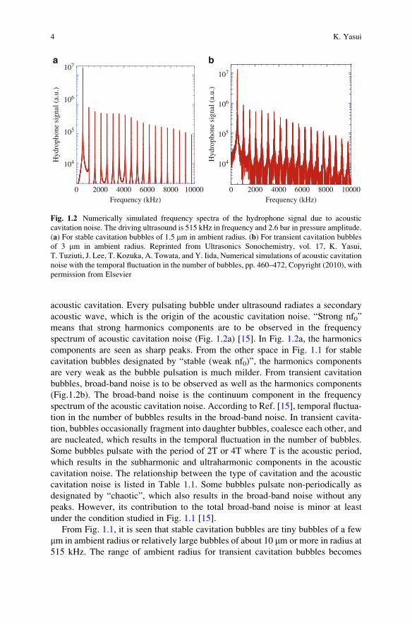
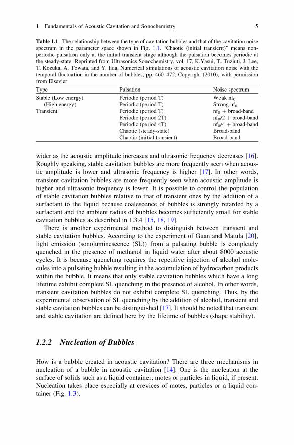
acoustic cavitation. Every pulsating bubble under ultrasound radiates a secondary
acoustic wave, which is the origin of the acoustic cavitation noise. “Strong nf0”
means that strong harmonics components are to be observed in the frequency
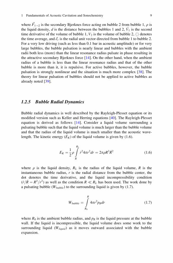
spectrum of acoustic cavitation noise (Fig. 1.2a) [15]. In Fig. 1.2a, the harmonics
components are seen as sharp peaks. From the other space in Fig. 1.1 for stable
cavitation bubbles designated by “stable (weak nf0)”, the harmonics components
are very weak as the bubble pulsation is much milder. From transient cavitation
bubbles, broad-band noise is to be observed as well as the harmonics components
(Fig.1.2b). The broad-band noise is the continuum component in the frequency
spectrum of the acoustic cavitation noise. According to Ref. [15], temporal fluctua-
tion in the number of bubbles results in the broad-band noise. In transient cavita-
tion, bubbles occasionally fragment into daughter bubbles, coalesce each other, and
are nucleated, which results in the temporal fluctuation in the number of bubbles.
Some bubbles pulsate with the period of 2T or 4T where T is the acoustic period,
which results in the subharmonic and ultraharmonic components in the acoustic
cavitation noise. The relationship between the type of cavitation and the acoustic
cavitation noise is listed in Table 1.1. Some bubbles pulsate non-periodically as
designated by “chaotic”, which also results in the broad-band noise without any
peaks. However, its contribution to the total broad-band noise is minor at least
under the condition studied in Fig. 1.1 [15].
From Fig. 1.1, it is seen that stable cavitation bubbles are tiny bubbles of a few
mm in ambient radius or relatively large bubbles of about 10 mm or more in radius at
515 kHz. The range of ambient radius for transient cavitation bubbles becomes
104
105
106
107
10000
Hyd
roph
one
sign
al (
a.u.
)
Frequency (kHz)0 2000 4000 6000 8000
104
105
106
107
10000
Hyd
roph
one
sign
al (
a.u.
)
Frequency (kHz)0 2000
a b
4000 6000 8000
Fig. 1.2 Numerically simulated frequency spectra of the hydrophone signal due to acoustic
cavitation noise. The driving ultrasound is 515 kHz in frequency and 2.6 bar in pressure amplitude.
(a) For stable cavitation bubbles of 1.5 mm in ambient radius. (b) For transient cavitation bubbles
of 3 mm in ambient radius. Reprinted from Ultrasonics Sonochemistry, vol. 17, K. Yasui,
T. Tuziuti, J. Lee, T. Kozuka, A. Towata, and Y. Iida, Numerical simulations of acoustic cavitation
noise with the temporal fluctuation in the number of bubbles, pp. 460–472, Copyright (2010), with
permission from Elsevier
4 K. Yasui
wider as the acoustic amplitude increases and ultrasonic frequency decreases [16].
Roughly speaking, stable cavitation bubbles are more frequently seen when acous-
tic amplitude is lower and ultrasonic frequency is higher [17]. In other words,
transient cavitation bubbles are more frequently seen when acoustic amplitude is
higher and ultrasonic frequency is lower. It is possible to control the population
of stable cavitation bubbles relative to that of transient ones by the addition of a
surfactant to the liquid because coalescence of bubbles is strongly retarded by a
surfactant and the ambient radius of bubbles becomes sufficiently small for stable
cavitation bubbles as described in 1.3.4 [15, 18, 19].
There is another experimental method to distinguish between transient and
stable cavitation bubbles. According to the experiment of Guan and Matula [20],
light emission (sonoluminescence (SL)) from a pulsating bubble is completely
quenched in the presence of methanol in liquid water after about 8000 acoustic
cycles. It is because quenching requires the repetitive injection of alcohol mole-
cules into a pulsating bubble resulting in the accumulation of hydrocarbon products
within the bubble. It means that only stable cavitation bubbles which have a long
lifetime exhibit complete SL quenching in the presence of alcohol. In other words,
transient cavitation bubbles do not exhibit complete SL quenching. Thus, by the
experimental observation of SL quenching by the addition of alcohol, transient and
stable cavitation bubbles can be distinguished [17]. It should be noted that transient
and stable cavitation are defined here by the lifetime of bubbles (shape stability).
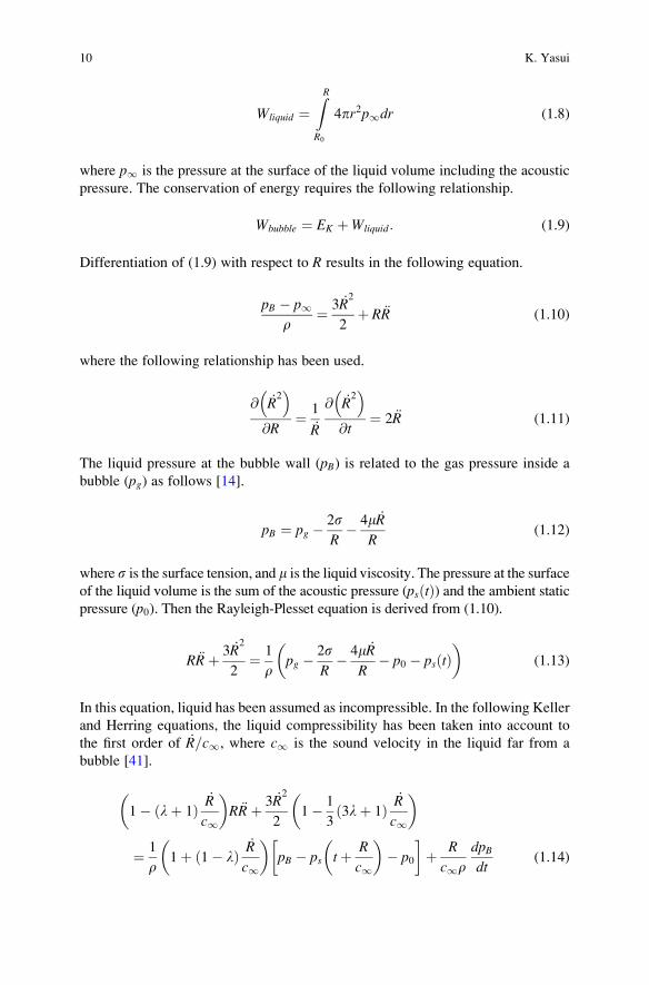
1.2.2 Nucleation of Bubbles
How is a bubble created in acoustic cavitation? There are three mechanisms in
nucleation of a bubble in acoustic cavitation [14]. One is the nucleation at the
surface of solids such as a liquid container, motes or particles in liquid, if present.
Nucleation takes place especially at crevices of motes, particles or a liquid con-
tainer (Fig. 1.3).
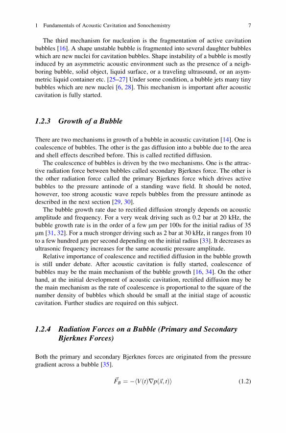
Table 1.1 The relationship between the type of cavitation bubbles and that of the cavitation noise
spectrum in the parameter space shown in Fig. 1.1. “Chaotic (initial transient)” means non-
periodic pulsation only at the initial transient stage although the pulsation becomes periodic at
the steady-state. Reprinted from Ultrasonics Sonochemistry, vol. 17, K.Yasui, T. Tuziuti, J. Lee,
T. Kozuka, A. Towata, and Y. Iida, Numerical simulations of acoustic cavitation noise with the
temporal fluctuation in the number of bubbles, pp. 460–472, Copyright (2010), with permission
from Elsevier
Type Pulsation Noise spectrum
Stable (Low energy)
(High energy)
Periodic (period T)
Periodic (period T)
Weak nf0Strong nf0
Transient Periodic (period T)
Periodic (period 2T)
Periodic (period 4T)
Chaotic (steady-state)
Chaotic (initial transient)
nf0 þ broad-band
nf0/2 þ broad-band
nf0/4 þ broad-band
Broad-band
Broad-band
1 Fundamentals of Acoustic Cavitation and Sonochemistry 5
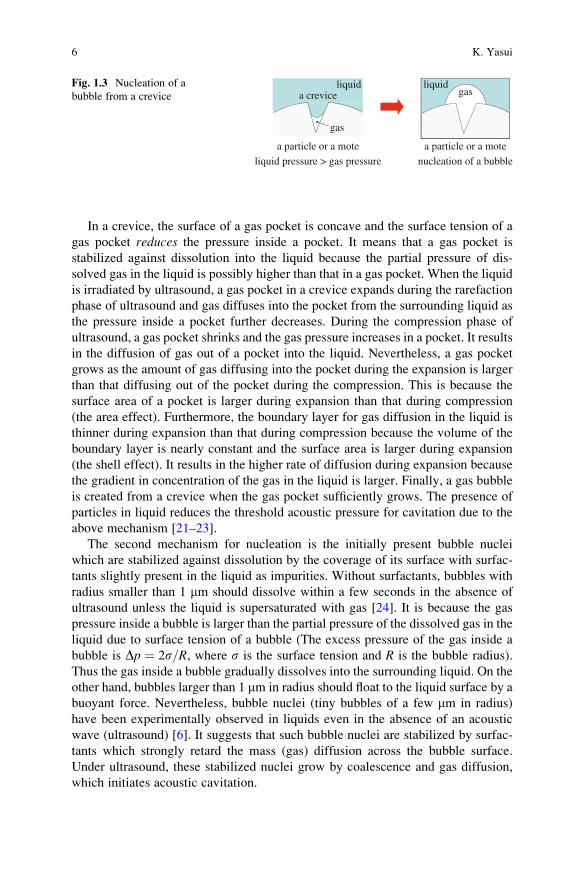
In a crevice, the surface of a gas pocket is concave and the surface tension of a
gas pocket reduces the pressure inside a pocket. It means that a gas pocket is
stabilized against dissolution into the liquid because the partial pressure of dis-
solved gas in the liquid is possibly higher than that in a gas pocket. When the liquid
is irradiated by ultrasound, a gas pocket in a crevice expands during the rarefaction
phase of ultrasound and gas diffuses into the pocket from the surrounding liquid as
the pressure inside a pocket further decreases. During the compression phase of
ultrasound, a gas pocket shrinks and the gas pressure increases in a pocket. It results
in the diffusion of gas out of a pocket into the liquid. Nevertheless, a gas pocket
grows as the amount of gas diffusing into the pocket during the expansion is larger
than that diffusing out of the pocket during the compression. This is because the
surface area of a pocket is larger during expansion than that during compression
(the area effect). Furthermore, the boundary layer for gas diffusion in the liquid is
thinner during expansion than that during compression because the volume of the
boundary layer is nearly constant and the surface area is larger during expansion
(the shell effect). It results in the higher rate of diffusion during expansion because
the gradient in concentration of the gas in the liquid is larger. Finally, a gas bubble
is created from a crevice when the gas pocket sufficiently grows. The presence of
particles in liquid reduces the threshold acoustic pressure for cavitation due to the
above mechanism [21–23].
The second mechanism for nucleation is the initially present bubble nuclei
which are stabilized against dissolution by the coverage of its surface with surfac-
tants slightly present in the liquid as impurities. Without surfactants, bubbles with
radius smaller than 1 mm should dissolve within a few seconds in the absence of
ultrasound unless the liquid is supersaturated with gas [24]. It is because the gas
pressure inside a bubble is larger than the partial pressure of the dissolved gas in the
liquid due to surface tension of a bubble (The excess pressure of the gas inside a
bubble is Dp ¼ 2s=R, where s is the surface tension and R is the bubble radius).
Thus the gas inside a bubble gradually dissolves into the surrounding liquid. On the
other hand, bubbles larger than 1 mm in radius should float to the liquid surface by a
buoyant force. Nevertheless, bubble nuclei (tiny bubbles of a few mm in radius)
have been experimentally observed in liquids even in the absence of an acoustic
wave (ultrasound) [6]. It suggests that such bubble nuclei are stabilized by surfac-
tants which strongly retard the mass (gas) diffusion across the bubble surface.
Under ultrasound, these stabilized nuclei grow by coalescence and gas diffusion,
which initiates acoustic cavitation.
liquida crevice
liquidgas
gas
a particle or a mote a particle or a mote
liquid pressure > gas pressure nucleation of a bubble
Fig. 1.3 Nucleation of a
bubble from a crevice
6 K. Yasui
The third mechanism for nucleation is the fragmentation of active cavitation
bubbles [16]. A shape unstable bubble is fragmented into several daughter bubbles
which are new nuclei for cavitation bubbles. Shape instability of a bubble is mostly
induced by an asymmetric acoustic environment such as the presence of a neigh-
boring bubble, solid object, liquid surface, or a traveling ultrasound, or an asym-
metric liquid container etc. [25–27] Under some condition, a bubble jets many tiny
bubbles which are new nuclei [6, 28]. This mechanism is important after acoustic
cavitation is fully started.
1.2.3 Growth of a Bubble
There are two mechanisms in growth of a bubble in acoustic cavitation [14]. One is
coalescence of bubbles. The other is the gas diffusion into a bubble due to the area
and shell effects described before. This is called rectified diffusion.
The coalescence of bubbles is driven by the two mechanisms. One is the attrac-
tive radiation force between bubbles called secondary Bjerknes force. The other is
the other radiation force called the primary Bjerknes force which drives active
bubbles to the pressure antinode of a standing wave field. It should be noted,
however, too strong acoustic wave repels bubbles from the pressure antinode as
described in the next section [29, 30].
The bubble growth rate due to rectified diffusion strongly depends on acoustic
amplitude and frequency. For a very weak driving such as 0.2 bar at 20 kHz, the
bubble growth rate is in the order of a few mm per 100s for the initial radius of 35
mm [31, 32]. For a much stronger driving such as 2 bar at 30 kHz, it ranges from 10
to a few hundred mm per second depending on the initial radius [33]. It decreases as
ultrasonic frequency increases for the same acoustic pressure amplitude.
Relative importance of coalescence and rectified diffusion in the bubble growth
is still under debate. After acoustic cavitation is fully started, coalescence of
bubbles may be the main mechanism of the bubble growth [16, 34]. On the other
hand, at the initial development of acoustic cavitation, rectified diffusion may be
the main mechanism as the rate of coalescence is proportional to the square of the
number density of bubbles which should be small at the initial stage of acoustic
cavitation. Further studies are required on this subject.
1.2.4 Radiation Forces on a Bubble (Primary and SecondaryBjerknes Forces)
Both the primary and secondary Bjerknes forces are originated from the pressure
gradient across a bubble [35].
~FB ¼ � VðtÞrpð~x; tÞh i (1.2)
1 Fundamentals of Acoustic Cavitation and Sonochemistry 7
where ~FB is the primary or secondary Bjerknes force, VðtÞ is the instantaneous
bubble volume,r ¼ �@@x ;
@@y ;
@@z
�in xyz-coordinate, pð~x; tÞ is the instantaneous local
pressure at position ~x, and h i denotes the time average. For the primary Bjerknes
force, pð~x; tÞ is the driving ultrasound. On the other hand, for the secondary
Bjerknes force, pð~x; tÞ is the acoustic wave radiated by a neighboring bubble.
When the driving ultrasound is a standing wave, pð~x; tÞ is expressed as follows
for the primary Bjerknes force.
pð~x; tÞ ¼ pa cosð~k �~xÞ sinot (1.3)
where pa is the acoustic pressure amplitude, ~k is the wave vector, and o is the
angular frequency. Then, the primary Bjerknes force (~FPB) is given by the following
equation.
~FPB ¼ pa~k sinð~k �~xÞ VðtÞ sinoth i (1.4)
When the bubble pulsation is in phase with the driving ultrasound, a bubble is
attracted to the pressure antinode of a standing wave field. For a very low driving
such as less than 0.1 bar in acoustic amplitude, bubble pulsation is nearly linear and
this condition coincides with smaller ambient radius than the linear resonance
radius. For active bubbles, pulsation is strongly nonlinear, and the situation is
more complex. For example, at 20 kHz, an active bubble of smaller ambient radius
than the linear resonance radius is repelled from the pressure antinode when the
acoustic pressure amplitude is larger than about 1.8 bar [29, 30]. This is because a
bubble continues expanding even during the compression phase of ultrasound due
to the inertia of the surrounding liquid. To active bubbles (“transient cavitation
bubbles” by the definition based on activity of bubbles), the linear theory can not be
applied.
In a traveling wave of ultrasound, most active bubbles are pushed toward the
direction of the wave propagation by the primary Bjerknes force. Furthermore,
there is a fluid flow in the direction of the wave propagation called acoustic
streaming [36]. Acoustic streaming is caused by the attenuation of a traveling
wave resulting in the net radiation force in the direction of the wave propagation.
The attenuation is caused by both viscosity of the liquid and the cavitation bubbles.
Furthermore, moving bubbles driven by the primary Bjerknes force drag the
surrounding fluid. The resulting fluid flow is called quasi acoustic streaming [37].
While the secondary Bjerknes force is always attractive if the ambient radius is
the same between bubbles, it can be repulsive if the ambient radius is different [38].
The magnitude as well as the sign of the secondary Bjerknes force is a strong
function of the ambient bubble radii of two bubbles, the acoustic pressure ampli-
tude, and the acoustic frequency. It is calculated by (1.5).
~F1!2 ¼ r4pd2
€V1V2
� �~er (1.5)
8 K. Yasui
where ~F1!2 is the secondary Bjerknes force acting on bubble 2 from bubble 1, r is
the liquid density, d is the distance between the bubbles 1 and 2, €V1 is the second
time derivative of the volume of bubble 1, V2 is the volume of bubble 2, h i denotesthe time average, and~er is the radial unit vector directed from bubble 1 to bubble 2.
For a very low driving (such as less than 0.1 bar in acoustic amplitude) or for very
large bubbles, the bubble pulsation is nearly linear and bubbles with the ambient
radii both less (more) than the linear resonance radius pulsate in phase resulting in
the attractive secondary Bjerknes force [14]. On the other hand, when the ambient
radius of a bubble is less than the linear resonance radius and that of the other
bubble is more than it, it is repulsive. For active bubbles, however, the bubble
pulsation is strongly nonlinear and the situation is much more complex [38]. The
theory for linear pulsation of bubbles should not be applied to active bubbles as
already noted [39].
1.2.5 Bubble Radial Dynamics
Bubble radial dynamics is well described by the Rayleigh-Plesset equation or its
modified version such as Keller and Herring equations [40]. The Rayleigh-Plesset
equation is derived as follows [14]. Consider a liquid volume surrounding a
pulsating bubble such that the liquid volume is much larger than the bubble volume
and that the radius of the liquid volume is much smaller than the acoustic wave-
length. The kinetic energy (EK) of the liquid volume is given by (1.6).
EK ¼ 1
2rZRL
R
_r24pr2dr ¼ 2prR3 _R2 (1.6)
where r is the liquid density, RL is the radius of the liquid volume, R is the
instantaneous bubble radius, r is the radial distance from the bubble center, the
dot denotes the time derivative, and the liquid incompressibility condition
( _r= _R ¼ R2=r2) as well as the condition R � RL has been used. The work done by
a pulsating bubble (Wbubble) to the surrounding liquid is given by (1.7).
Wbubble ¼ZRR0
4pr2pBdr (1.7)
where R0 is the ambient bubble radius, and pB is the liquid pressure at the bubble
wall. If the liquid is incompressible, the liquid volume does some work to the
surrounding liquid (Wliquid) as it moves outward associated with the bubble
expansion.
1 Fundamentals of Acoustic Cavitation and Sonochemistry 9
Wliquid ¼ZRR0
4pr2p1dr (1.8)
where p1 is the pressure at the surface of the liquid volume including the acoustic
pressure. The conservation of energy requires the following relationship.
Wbubble ¼ EK þWliquid: (1.9)
Differentiation of (1.9) with respect to R results in the following equation.
pB � p1r
¼ 3 _R2
2þ R €R (1.10)
where the following relationship has been used.
@ _R2
� �@R
¼ 1
_R
@ _R2
� �@t
¼ 2 €R (1.11)
The liquid pressure at the bubble wall (pB) is related to the gas pressure inside a
bubble (pg) as follows [14].
pB ¼ pg � 2sR
� 4m _R
R(1.12)
where s is the surface tension, and m is the liquid viscosity. The pressure at the surface
of the liquid volume is the sum of the acoustic pressure (psðtÞ) and the ambient static
pressure (p0). Then the Rayleigh-Plesset equation is derived from (1.10).
R €Rþ 3 _R2
2¼ 1
rpg � 2s
R� 4m _R
R� p0 � psðtÞ
� (1.13)
In this equation, liquid has been assumed as incompressible. In the following Keller
and Herring equations, the liquid compressibility has been taken into account to
the first order of _R=c1, where c1 is the sound velocity in the liquid far from a
bubble [41].
1� lþ 1ð Þ_R
c1
� R €Rþ 3 _R
2
21� 1
33lþ 1ð Þ
_R
c1
�
¼ 1
r1þ 1� lð Þ
_R
c1
� pB � ps tþ R
c1
� � p0
�þ R
c1rdpBdt
(1.14)
10 K. Yasui
where l ¼ 0 or 1 for Keller or Herring equation, respectively, and ps�tþ R
c1
�is the
instantaneous acoustic pressure at time tþ Rc1
. As a similar equation, Gilmore
equation has also been widely used [41].
1.2.6 Inertial Collapse (Rayleigh Collapse)
Now the bubble collapse is discussed using the Rayleigh-Plesset equation. After the
bubble expansion, a bubble collapses. During the bubble collapse, important terms
in the Rayleigh-Plesset equation are the two terms in the left hand side of (1.13).
Then, the bubble wall acceleration is expressed as follows.
€R ¼ � 3 _R2
2R(1.15)
Thus, it is always negative. It means that the speed of the bubble collapse increases
with time (The negative bubble-wall velocity further decreases). As the speed of the
bubble collapse increases, the magnitude of the bubble wall acceleration increases
according to (1.15). It means that the speed of the bubble collapse automatically
increases more and more with time. This is caused by the inertia of the surrounding
liquid ingoing into a collapsing bubble as well as the spherically shrinking geome-
try. Such a bubble collapse is called inertial collapse or Rayleigh collapse [40].
It has been shown theoretically that the speed of the bubble collapse is limited by
the sound speed in the liquid at the bubble wall [42]. The sound speed is a function
of pressure and density of the liquid as follows.
cL;B ¼ffiffiffiffiffiffiffiffiffiffiffiffiffiffiffiffiffiffiffiffiffiffiffiffiffiffiffiffiffiffiffiffiffiffiffiffi7:15 pB þ Bð Þ rL;iq
(1.16)
where cL;B is the sound speed in the liquid at the bubble wall, B ¼ 3:049� 108 Pa,
and rL;i is the liquid density at the bubble wall. The sound speed (cL;B) increases asthe bubble collapses up to about 3000 m/s (about two times of the ambient sound
speed (1500 m/s) in water), which is the upper limit for the speed of the bubble
collapse.
Finally, the bubble collapse stops when the pressure inside a bubble (pg) in the
right hand side of (1.13) dramatically increases as the density inside a bubble nearly
reaches that of a condensed phase (A bubble is almost completely occupied by the
van der Waals hard-cores of gas and vapor molecules at that moment). At the same
time, the temperature and pressure inside a bubble dramatically increase.
In Fig. 1.4a, an example of the radius-time curve for a stably pulsating bubble
calculated by the modified Keller equation is shown for one acoustic cycle [43].
After the bubble expansion during the rarefaction phase of ultrasound, a bubble
strongly collapses, which is the inertial or Rayleigh collapse. After the collapse,
there is a bouncing radial motion of a bubble. In Fig.1.4b, the calculated flux of OH
1 Fundamentals of Acoustic Cavitation and Sonochemistry 11
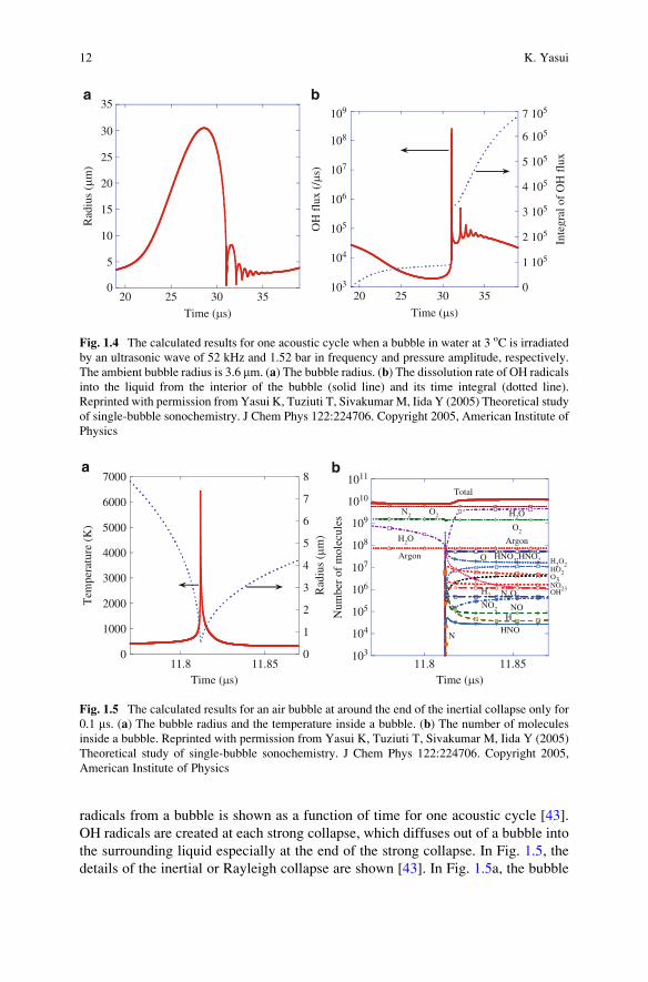
radicals from a bubble is shown as a function of time for one acoustic cycle [43].
OH radicals are created at each strong collapse, which diffuses out of a bubble into
the surrounding liquid especially at the end of the strong collapse. In Fig. 1.5, the
details of the inertial or Rayleigh collapse are shown [43]. In Fig. 1.5a, the bubble
0
5
10
15
20
25
30
35
20 25 30 35
Rad
ius
(mm
)
Time (ms)
a b
Time (ms)
103
104
105
106
107
108
109
0
7 105
6 105
5 105
4 105
3 105
2 105
1 105
20 25 30 35
OH
flu
x (/ms
)
Inte
gral
of
OH
flu
x
Fig. 1.4 The calculated results for one acoustic cycle when a bubble in water at 3 oC is irradiated
by an ultrasonic wave of 52 kHz and 1.52 bar in frequency and pressure amplitude, respectively.
The ambient bubble radius is 3.6 mm. (a) The bubble radius. (b) The dissolution rate of OH radicals
into the liquid from the interior of the bubble (solid line) and its time integral (dotted line).
Reprinted with permission from Yasui K, Tuziuti T, Sivakumar M, Iida Y (2005) Theoretical study
of single-bubble sonochemistry. J Chem Phys 122:224706. Copyright 2005, American Institute of
Physics
0
1000
2000
3000
4000
5000
6000
7000a b
0
1
2
3
4
5
6
7
8
11.8 11.85
Tem
pera
ture
(K
)
Rad
ius
(mm
)
Time (ms)
103
104
105
106
107
108
109
1010
1011
11.8 11.85
Num
ber
of m
olec
ules
Time (ms)
Total
N2 O2
H2
O2
O
H2O
H2O2HO2
NO23OH
O3
H2O
N2ONO2
Argon
Argon
HNO3,HNO2
NOH
HNON
Fig. 1.5 The calculated results for an air bubble at around the end of the inertial collapse only for
0.1 ms. (a) The bubble radius and the temperature inside a bubble. (b) The number of molecules
inside a bubble. Reprinted with permission from Yasui K, Tuziuti T, Sivakumar M, Iida Y (2005)
Theoretical study of single-bubble sonochemistry. J Chem Phys 122:224706. Copyright 2005,
American Institute of Physics
12 K. Yasui
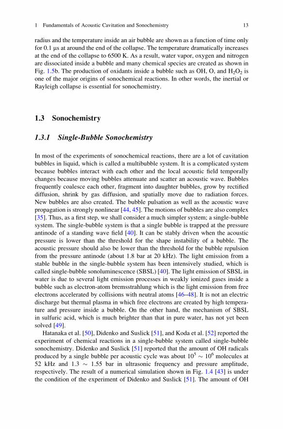
radius and the temperature inside an air bubble are shown as a function of time only
for 0.1 ms at around the end of the collapse. The temperature dramatically increases
at the end of the collapse to 6500 K. As a result, water vapor, oxygen and nitrogen
are dissociated inside a bubble and many chemical species are created as shown in
Fig. 1.5b. The production of oxidants inside a bubble such as OH, O, and H2O2 is
one of the major origins of sonochemical reactions. In other words, the inertial or
Rayleigh collapse is essential for sonochemistry.
1.3 Sonochemistry
1.3.1 Single-Bubble Sonochemistry
In most of the experiments of sonochemical reactions, there are a lot of cavitation
bubbles in liquid, which is called a multibubble system. It is a complicated system
because bubbles interact with each other and the local acoustic field temporally
changes because moving bubbles attenuate and scatter an acoustic wave. Bubbles
frequently coalesce each other, fragment into daughter bubbles, grow by rectified
diffusion, shrink by gas diffusion, and spatially move due to radiation forces.
New bubbles are also created. The bubble pulsation as well as the acoustic wave
propagation is strongly nonlinear [44, 45]. The motions of bubbles are also complex
[35]. Thus, as a first step, we shall consider a much simpler system; a single-bubble
system. The single-bubble system is that a single bubble is trapped at the pressure
antinode of a standing wave field [40]. It can be stably driven when the acoustic
pressure is lower than the threshold for the shape instability of a bubble. The
acoustic pressure should also be lower than the threshold for the bubble repulsion
from the pressure antinode (about 1.8 bar at 20 kHz). The light emission from a
stable bubble in the single-bubble system has been intensively studied, which is
called single-bubble sonoluminescence (SBSL) [40]. The light emission of SBSL in
water is due to several light emission processes in weakly ionized gases inside a
bubble such as electron-atom bremsstrahlung which is the light emission from free
electrons accelerated by collisions with neutral atoms [46–48]. It is not an electric
discharge but thermal plasma in which free electrons are created by high tempera-
ture and pressure inside a bubble. On the other hand, the mechanism of SBSL
in sulfuric acid, which is much brighter than that in pure water, has not yet been
solved [49].
Hatanaka et al. [50], Didenko and Suslick [51], and Koda et al. [52] reported the
experiment of chemical reactions in a single-bubble system called single-bubble
sonochemistry. Didenko and Suslick [51] reported that the amount of OH radicals
produced by a single bubble per acoustic cycle was about 105 � 106 molecules at
52 kHz and 1.3 � 1.55 bar in ultrasonic frequency and pressure amplitude,
respectively. The result of a numerical simulation shown in Fig. 1.4 [43] is under
the condition of the experiment of Didenko and Suslick [51]. The amount of OH
1 Fundamentals of Acoustic Cavitation and Sonochemistry 13
radicals calculated by the numerical simulation sufficiently agrees with the experi-
mental data. It indicates that the theoretical model used in the numerical simulation
is sufficiently accurate at least under the condition.
According to Didenko and Suslick [51], the amount of nitrite ions (NO2�)
produced by a bubble per acoustic cycle was about 106 � 107 molecules. Koda
et al. [52] also reported a similar value.
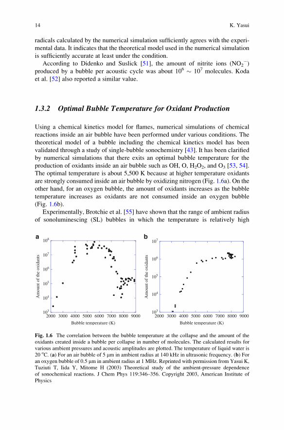
1.3.2 Optimal Bubble Temperature for Oxidant Production
Using a chemical kinetics model for flames, numerical simulations of chemical
reactions inside an air bubble have been performed under various conditions. The
theoretical model of a bubble including the chemical kinetics model has been
validated through a study of single-bubble sonochemistry [43]. It has been clarified
by numerical simulations that there exits an optimal bubble temperature for the
production of oxidants inside an air bubble such as OH, O, H2O2, and O3 [53, 54].
The optimal temperature is about 5,500 K because at higher temperature oxidants
are strongly consumed inside an air bubble by oxidizing nitrogen (Fig. 1.6a). On the
other hand, for an oxygen bubble, the amount of oxidants increases as the bubble
temperature increases as oxidants are not consumed inside an oxygen bubble
(Fig. 1.6b).
Experimentally, Brotchie et al. [55] have shown that the range of ambient radius
of sonoluminescing (SL) bubbles in which the temperature is relatively high
103
104
105
106
107
108
2000 3000 4000 5000 6000 7000 8000 9000
Am
ount
of
the
oxid
ants
Bubble temperature (K)
103
104
105
106
107
2000 3000 4000 5000 6000 7000 8000 9000
Am
ount
of
the
oxid
ants
Bubble temperature (K)
a b
Fig. 1.6 The correlation between the bubble temperature at the collapse and the amount of the
oxidants created inside a bubble per collapse in number of molecules. The calculated results for
various ambient pressures and acoustic amplitudes are plotted. The temperature of liquid water is
20 oC. (a) For an air bubble of 5 mm in ambient radius at 140 kHz in ultrasonic frequency. (b) For
an oxygen bubble of 0.5 mm in ambient radius at 1 MHz. Reprinted with permission from Yasui K,
Tuziuti T, Iida Y, Mitome H (2003) Theoretical study of the ambient-pressure dependence
of sonochemical reactions. J Chem Phys 119:346–356. Copyright 2003, American Institute of
Physics
14 K. Yasui
completely differs from that of chemically active bubbles which produce oxidants
and glow by chemiluminescence in an aqueous luminol solution saturated with air.
It suggests that the temperature inside chemically active bubbles is lower than that
inside SL bubbles for an air bubble. It agrees with the results of the numerical
simulations described above. The experimental method to measure the range of
ambient radius of SL bubbles (or sonochemiluminescing (SCL) bubbles in an
aqueous luminol solution) is based on the dissolution of bubbles during the pulse-
off time of pulsed ultrasound [19]. Bubbles with larger ambient radius need longer
pulse-off time for complete dissolution. As the pulse-off time increases, the SL (or
SCL) intensity decreases because more bubbles dissolve during the pulse-off time
and the number of bubbles decreases. From the dependence of the SL (or SCL)
intensity on the pulse-off time, the range of ambient radius of SL (or SCL) bubbles
is deduced [19].
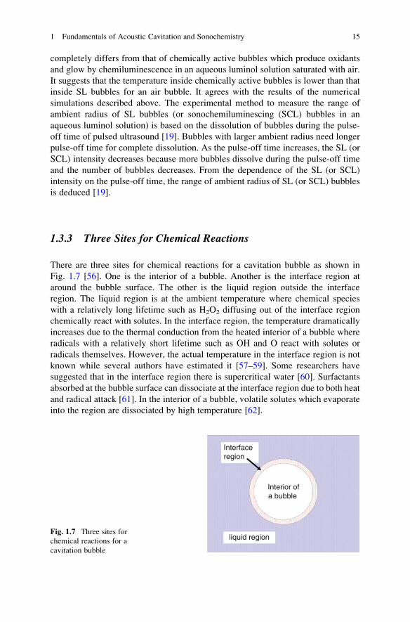
1.3.3 Three Sites for Chemical Reactions
There are three sites for chemical reactions for a cavitation bubble as shown in
Fig. 1.7 [56]. One is the interior of a bubble. Another is the interface region at
around the bubble surface. The other is the liquid region outside the interface
region. The liquid region is at the ambient temperature where chemical species
with a relatively long lifetime such as H2O2 diffusing out of the interface region
chemically react with solutes. In the interface region, the temperature dramatically
increases due to the thermal conduction from the heated interior of a bubble where
radicals with a relatively short lifetime such as OH and O react with solutes or
radicals themselves. However, the actual temperature in the interface region is not
known while several authors have estimated it [57–59]. Some researchers have
suggested that in the interface region there is supercritical water [60]. Surfactants
absorbed at the bubble surface can dissociate at the interface region due to both heat
and radical attack [61]. In the interior of a bubble, volatile solutes which evaporate
into the region are dissociated by high temperature [62].
Interior ofa bubble
Interfaceregion
liquid regionFig. 1.7 Three sites for
chemical reactions for a
cavitation bubble
1 Fundamentals of Acoustic Cavitation and Sonochemistry 15

As stated above, more studies are required in future with regard to the interface
region. What is the temperature and pressure in the interface region? What is
the lifetime of OH radicals and O atoms in the interface region [63]? Is there
supercritical water in the region?
1.3.4 Size of Active Bubbles
In some literature, there is a description that a bubble with linear resonance radius
is active in sonoluminescence and sonochemical reactions. However, as already
noted, bubble pulsation is intrinsically nonlinear for active bubbles. Thus, the
concept of the linear resonance is not applicable to active bubbles (That is only
applicable to a linearly pulsating bubble under very weak ultrasound such as 0.1 bar
in pressure amplitude). Furthermore, a bubble with the linear resonance radius can
be inactive in sonoluminescence and sonochemical reactions [39]. In Fig. 1.8, the
calculated expansion ratio (Rmax / R0, where Rmax is the maximum radius and R0 is
the ambient radius of a bubble) is shown as a function of the ambient radius (R0)
for various acoustic amplitudes at 300 kHz [39]. It is seen that the ambient radius
for the peak in the expansion ratio decreases as the acoustic pressure amplitude
increases. While the linear resonance radius is 11 mm at 300 kHz, the ambient radius
for the peak at 3 bar in pressure amplitude is about 0.4 mm. Even at the pressure
amplitude of 0.5 bar, it is about 5 mm, which is much smaller than the linear
resonance radius.
In Fig. 1.9, the results of numerical simulations at 300 kHz and 3 bar in
ultrasonic frequency and pressure amplitude, respectively are shown as a function
of ambient radius [39]. In Fig. 1.9a, the temperature inside a bubble at the end of the
bubble collapse is shown with the molar fraction of water vapor inside a bubble.
1
10
100
0.1 1 10 100
Rm
ax /
R0
Ambient bubble radius (mm)
pa = 3 bar
2 bar
1 bar
0.5 bar
Fig. 1.8 The calculated
expansion ratio (Rmax/R0) as a
function of ambient bubble
radius for various acoustic
amplitudes at 300 kHz. Both
the horizontal and vertical
axes are in logarithmic scale.
Reprinted with permission
from Yasui K, Tuziuti T, Lee
J, Kozuka T, Towata A, Iida
Y (2008) The range of
ambient radius for an active
bubble in sonoluminescence
and sonochemical reactions.
J Chem Phys 128:184705.
Copyright 2008, American
Institute of Physics
16 K. Yasui