theoretical investigation on the performance of ... distillation column is the basis for its ... are...
TRANSCRIPT
Abstract—In this paper, the performance of a distillation
column with a multicomponent hydrocarbon mixture as a feed
is theoretically studied. The rigorous solution technique
namely the inside out method has been used to predict the
performance of the system under study. The mathematical
model of the inside out method has been developed and
detailed simulation studies have been carried out to predict the
performance of the separation of multicomponent
hydrocarbon mixture. In simulation studies, temperature
profile, composition profile and flow rates of both liquid and
vapor phases has been computed. The column profiles
computed using inside out method have been compared with
the profiles obtained using bubble point method, Lewis-
Matheson method and a SCDS column in CHEMCAD
process simulator. The effect of feed location on the column
performance has been studied and an optimum feed location
has been determined. The condenser and reboiler duties for
the column have also been calculated. The convergence
behavior of the inside out method has also been studied by
plotting a profile of its convergence parameters.
Index Terms—Equilibrium stage distillation, hydrocarbon
separation, inside out method, multicomponent mixture, two-
tier algorithm.
I. INTRODUCTION
Distillation is one of the popular separation technologies
and its application extends to a wide variety of process
industries. Theoretical investigation on the performance of
multicomponent distillation column is the basis for its
design and development. The rigorous methods such as the
Lewis-Matheson (LM) method [1], the Thiele- Geddes (TG)
method [2] are used for rigorous calculation of
multicomponent separation using multistage distillation
column. These methods are based on equation tearing
procedures. Friday and Smith [3] studied various equation
tearing procedures and revealed that there is no single
equation tearing procedure which could solve different
kinds of problems. Friday and Smith [3] further suggested
that bubble point method and sum rates methods be used for
narrow boiling and wide boiling feeds respectively. Boston
& Sullivan [4] and Naphtali & Sandholm [5] have proposed
more robust methods viz inside out method and Newton
Raphson method respectively and are useful to solve
complicated models.
Manuscript received June 27, 2015; revised October 29, 2015.
The authors are with the Department of Chemical Engineering, BITS-Pilani, K.K. Birla, Goa Campus, Goa 403726, India (corresponding author:
Sampatrao D. Manjare; tel.: +91-8322580112; fax: +91-8322557030; e-
mail: [email protected], [email protected])
Suitable choice of iteration variable in the inside out
method results in relatively small number of model
equations and hence require less computer memory and
computation time as compared to Newton Raphson method.
Simandl and Svrcek [6] present a comparison of
convergence time required for inside out method and
Newton Raphson method. The analysis reveals that inside
out method has a faster convergence time.
Therefore from above discussion, it is clear that inside out
approach is the preferred choice for simulating multistage
liquid vapor separators and is considered for study in this
paper.
To understand the detailed state of the art of the inside
out method, literature survey has been carried out and
presented below.
Boston and Sullivan [4] proposed a new algorithm for
steady state solution of the equations that describe
multicomponent, multistage separation processes. The
algorithm has been found to be exceptionally stable and
efficient. Boston [7] discussed the challenges faced in
solving models using class I methods namely bubble point
and sum rates method and class II methods namely Newton
Raphson method. Subsequently a detailed simulation
approach of inside out method for multicomponent
multistage liquid vapor separator has been presented.
Russell [8] suggested changes to the inside out method by
using a quasi-Newton approach to achieve all enthalpy
balance and performance specifications directly. Saeger and
Bishnoi [9] suggested a modified inside out algorithm for
highly non ideal liquid solutions using a two parameter
activity coefficient model. Jelinek [10] extends the methods
suggest by Russell [8] by providing a detailed methodology
and discusses certain advantages and potential shortcomings.
Shan et al. [11] suggests a method to efficiently solve
tridiagonal matrices containing off band elements. These
suggestions make solving columns with side strippers and
pump around much easier.
From above mentioned literature survey it is clear that
researchers across the world are striving to simplify the
inside out algorithm to be used for the simulation of
multicomponent distillation column.
II. INSIDE OUT METHOD
The inside out method was first presented by Boston and
Sullivan [4] as a new class of method for solving multistage
multicomponent distillation. It was initially applicable only
for the separation of an ideal hydrocarbon feed but its
capabilities were greatly extended to various complicated
Theoretical Investigation on the Performance of
Multicomponent Distillation Column for the Separation of
Hydrocarbon Mixture Using Inside out Approach
Shashwat Bansal and Sampatrao D. Manjare
International Journal of Chemical Engineering and Applications, Vol. 7, No. 4, August 2016
282doi: 10.18178/ijcea.2016.7.4.590
systems as studied by Russell [8], Jelinek [10], Simandl &
Svrcek [6], Trevino & Kisala [12], Saeger and Bishnoi [9]
and Shan et al. [11]. The inside out method can currently
solve for any multicomponent multistage liquid vapor
separation like distillation, absorption, stripping and
reboiled absorption. The method is very robust and permits
a range of allowable specifications. Also the method has
been found to be insensitive of initial estimates and
exceptionally stable. The method is known to converge for
difficult separation problems where traditional methods like
Thiele-Geddes [2] and Lewis-Matheson [1] fail and is
known to be just as efficient as any other technique while
solving simple columns.
To further understand the methodology of inside out
method, a mathematical model of a single stage liquid vapor
separator at steady state has been presented below.
A. The Mathematical Model
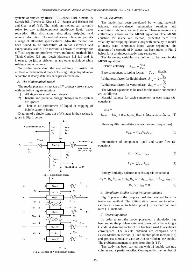
The model presents a cascade of N counter current stages
with the following assumptions
1) All stages are equilibrium stages.
2) Kinetic and potential energy changes in the system
are ignored.
3) There is no entrainment of liquid or trapping of
bubble vapor in liquid.
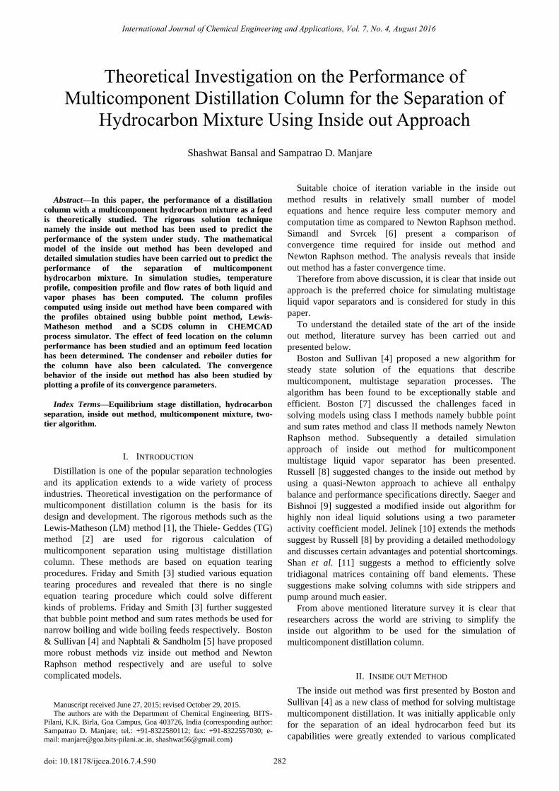
Diagram of a single stage out of N stages in the cascade is
given in Fig. 1 below.
Fig. 1. Equilibrium stage.
Fig. 2. Cascade of N equilibrium stages.
MESH Equations:
The model has been developed by writing material-
balance, energy-balance, summation relations and
equilibrium relations for each stage. These equations are
collectively known as the MESH equations. The MESH
equation for inside out method, presented here uses
volatility and stripping factors along with enthalpy to model
a steady state continuous liquid vapor separator. The
diagram of a cascade of N stages has been given in Fig. 2
below for a continuous steady state separator.
The following variables are defined to be used in the
MESH equations
Relative volatility: 𝛼𝑚,𝑛 =𝐾𝑚,𝑛
𝐾𝑏,𝑛
Base component stripping factor: 𝑆𝑏,𝑛 =𝐾𝑏,𝑛∗𝑉𝑛
𝐿𝑛
Withdrawal factor for liquid phase: 𝑅𝐿𝑛= 1 +
𝑈𝑛
𝐿𝑛
Withdrawal factor for vapor phase: 𝑅𝑣𝑛= 1 +
𝑊𝑛
𝑉𝑛
The MESH equations to be used for the inside out method
are as follows:
Material balance for each component at each stage (M-
equations)
−𝑓𝑚,𝑛 =
𝑙𝑚,𝑛−1 − (𝑅𝐿𝑛+ 𝛼𝑚,𝑛𝑆𝑏,𝑛𝑅𝑣𝑛
)𝑙𝑚,𝑛 + (𝛼𝑚,𝑛+1𝑆𝑏,𝑛+1)𝑙𝑚,𝑛+1 (1)
Phase equilibrium relations at each stage (E-equations)
𝑣𝑚,𝑛 = 𝛼𝑚,𝑛𝑆𝑏,𝑛𝑙𝑚,𝑛 (2)
Summations of component liquid and vapor flow (S-
equations)
𝑉𝑛 = ∑ 𝑣𝑚,𝑛𝑐𝑚=1 (3)
𝐿𝑛 = ∑ 𝑙𝑚,𝑛𝑐𝑚=1 (4)
Energy/Enthalpy balance at each stage(H-equations)
𝐻𝑛 = ℎ𝐿𝑛𝑅𝐿𝑛
𝐿𝑛 + ℎ𝑉𝑛𝑅𝑣𝑛
𝑉𝑛 − ℎ𝐿𝑛−1𝐿𝑛−1 − ℎ𝑉𝑛+1
𝑉𝑛+1 −
ℎ𝐹𝑛𝐹𝑛 − 𝑄𝑛 = 0 (5)
B. Simulation Studies Using Inside out Method
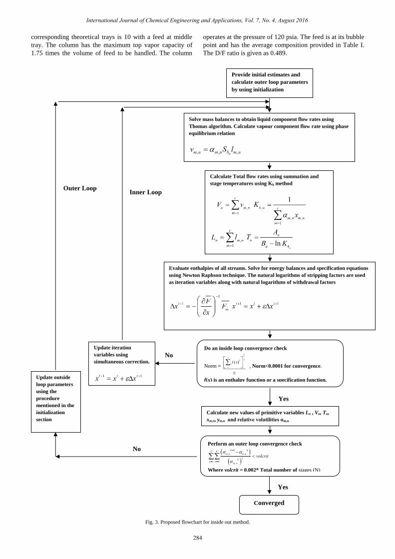
Fig. 3 presents the proposed solution methodology for
inside out method. The initialization procedure to obtain
estimates is similar to bubble point [13] method and sum
rates [14] methods.
C. Operating Mode
In order to test the model presented, a simulation has
been run on the problem statement given below by writing a
C code. A damping factor of 1.2 has been used to accelerate
convergence. The results obtained are compared with
Lewis-Matheson method [1] and bubble point method [13]
and process simulator CHEMCAD to validate the model.
The problem statement is taken from Smith [15].
The study has been carried out with 11 bubble cap tray
column and a partial reboiler. Consequently, the number of
International Journal of Chemical Engineering and Applications, Vol. 7, No. 4, August 2016
283
corresponding theoretical trays is 10 with a feed at middle
tray. The column has the maximum top vapor capacity of
1.75 times the volume of feed to be handled. The column
operates at the pressure of 120 psia. The feed is at its bubble
point and has the average composition provided in Table I.
The D/F ratio is given as 0.489.
Fig. 3. Proposed flowchart for inside out method.
Calculate new values of primitive variables Ln , Vn, Tn,
xm,n, ym,n and relative volatilities αm,n
Solve mass balances to obtain liquid component flow rates using
Thomas algorithm. Calculate vapour component flow rate using phase
equilibrium relation
Provide initial estimates and
calculate outer loop parameters
by using initialization
procedure
Calculate Total flow rates using summation and
stage temperatures using Kb method
Evaluate enthalpies of all streams. Solve for energy balances and specification equations
using Newton Raphson technique. The natural logarithms of stripping factors are used
as iteration variables along with natural logarithms of withdrawal factors
Do an inside loop convergence check
Norm = , Norm<0.0001 for convergence.
f(x) is an enthalpy function or a specification function.
Update iteration
variables using
simultaneous correction.
Perform an outer loop convergence check
Where volcrit = 0.002* Total number of stages (N)
Update outside
loop parameters
using the
procedure
mentioned in the
initialization
section
Converged
Inner Loop Outer Loop
Yes
Yes
No
No
International Journal of Chemical Engineering and Applications, Vol. 7, No. 4, August 2016
284
Further it is mentioned that column will only be operated
ifless than 7 mol% i-C5is present in the overhead and less
that 3 mol% n-C4is present in the bottoms.
1) Expressions for K-values and enthalpy
The expressions used for K-values and enthalpy have
been obtained by fitting values from data tables over a range
of temperatures and at a given pressure
2) Expression for K values
K(propane) = (0.00007*T*T)- (0.003*T) + 1.441
K(i-butane) = (0.00005*T*T) – (0.002*T) + 0.531
K(n-butane) = (0.00005*T*T) – (0.006*T) + 0.745
K(i-pentane) = (0.00003*T*T) – (0.004*T) + 0.438
K(n-pentane) = (0.00003*T*T) – (0.004*T) + 0.327
3) Expression for liquid enthalpy
Hl (propane) = ((0.061*T*T) + (18.43*T)+5056)*2.2*1.055
Hl (i-butane) = ((0.045*T*T) + (24.31*T)+5938)*2.2*1.055
Hl (n-butane) = ((0.027*T*T) + (30.12*T) + 5963)
*2.2*1.055
Hl (i-pentane) = ((0.047*T*T) + (28.61*T) + 7237)
*2.2*1.055
Hl (n-pentane) = ((0.049*T*T) + (29.17*T)+7438)
*2.2*1.055
4) Expression for vapor enthalpy
Hv (propane) = ((-0.009*T*T) + (27.74*T) + 11478)
*2.2*1.055
Hv (i-butane) = ((0.039*T*T)+(11.98*T)+14902)*2.2*1.055
Hv(n-butane) = ((0.045*T*T)+(8.686*T)+16582)*2.2*1.055
Hv (i-pentane) = ((0.063*T*T) + (4.127*T) + 20458)
*2.2*1.055
Hv (n-pentane) = ((0.00*T*T)+(28*T)+19300)*2.2*1.055
where temperature T is in oF and liquid and vapor enthalpy
Hl and Hv are in J/mol.
III. SOLUTION PROCEDURE
The model equations were solved for by writing a C code.
The material balances were solved using Thomas algorithm
and the energy balances were solved using simultaneous
correction. The results obtained are vapor flow rate, liquid
flow rate, temperature and composition of both phases at
each stage along with condenser and reboiler duties. The
model required three outer loop iterations to converge.
A. Convergence Criteria for Inner and Outer Loop
Table II presents the convergence criteria for inner and
outer loop. The inner loop convergence is based on how
close to zero the values of enthalpy and discrepancy are at
each stage while outer loop converges is based on closeness
of values of relative volatilities between two successive
iterations.
TABLE II: CONVERGENCE CRITERIA FOR INNER AND OUTER LOOP
Inner loop Outer loop
norm =|∑ 𝑓(𝑥)2𝑛
1 |1/2
𝑁
<0.0001 [16]
where f(x) is either the
enthalpy function Hn or the
discrepancy function D1 and D2.
∑ ∑(𝛼𝑚,𝑛
𝑘+1−𝛼𝑚,𝑛𝑘)
(𝛼𝑚,𝑛𝑘)
2𝑐𝑚=1
𝑁𝑛=1 <
𝑣𝑜𝑙𝑐𝑟𝑖𝑡[6]
where volcrit = 0.002* Total number of stages (N)
𝛼𝑚,𝑛 is the relative volatility of components with respect
to a base component.
IV. RESULTS AND DISCUSSION
This section provides the column profiles for temperature,
vapor & liquid composition and flow rates along with
inner and outer loop convergence parameters. Further it also
compares the result obtained from inside out approach with
results obtained using bubble point method [13] and Lewis
Matheson method [1]. Simulation results from a process
simulator namely CHEMCAD has also been compared with
inside out results. All the results are presented in the section
below.
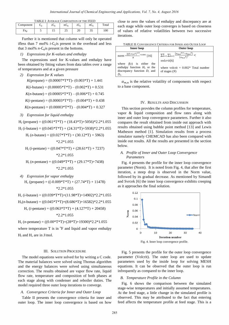
A. Profile of Inner and Outer Loop Convergence
Parameters
Fig. 4 presents the profile for the inner loop convergence
parameter (Norm). It is noted from Fig. 4, that after the first
iteration, a steep drop is observed in the Norm value,
followed by its gradual decrease. As mentioned by Simandl
and Svrcek [6] the inner loop convergence exhibits creeping
as it approaches the final solution.
Fig. 4. Inner loop convergence profile.
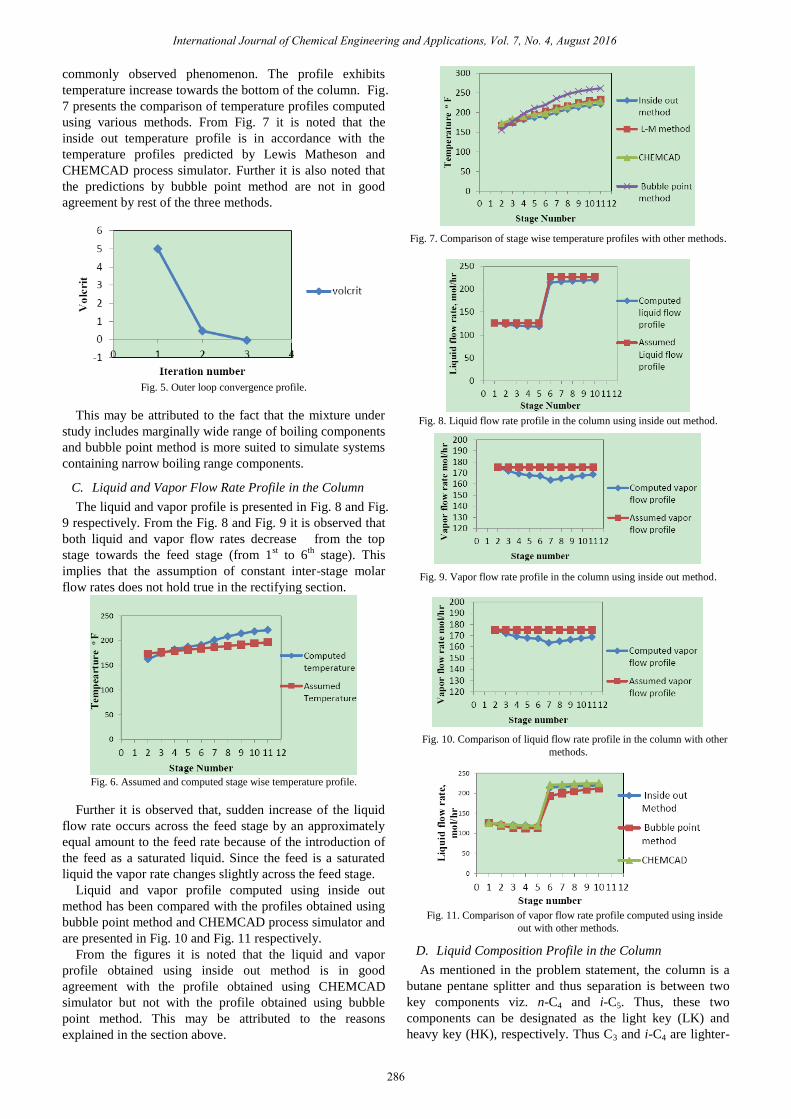
Fig. 5 presents the profile for the outer loop convergence
parameter (Volcrit). The outer loop are used to update
parameters used by the inside loop for solving MESH
equations. It can be observed that the outer loop is run
infrequently as compared to the inner loop.
B. Temperature Profile in the Column
Fig. 6 shows the comparison between the simulated
stage-wise temperatures and initially assumed temperatures.
At the feed stage, a little change in the simulated profile is
observed. This may be attributed to the fact that entering
feed affects the temperature profile at feed stage. This is a
International Journal of Chemical Engineering and Applications, Vol. 7, No. 4, August 2016
285
TABLE I: AVERAGE COMPOSITION OF THE FEED
Component C3 𝑖C4 𝑛C4 𝑖C5 nC5 Total
FxF 5 15 25 20 35 100
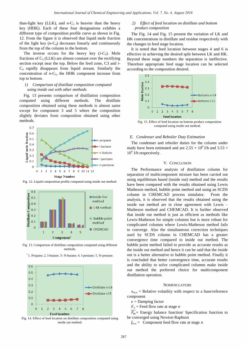
commonly observed phenomenon. The profile exhibits
temperature increase towards the bottom of the column. Fig.
7 presents the comparison of temperature profiles computed
using various methods. From Fig. 7 it is noted that the
inside out temperature profile is in accordance with the
temperature profiles predicted by Lewis Matheson and
CHEMCAD process simulator. Further it is also noted that
the predictions by bubble point method are not in good
agreement by rest of the three methods.
Fig. 5. Outer loop convergence profile.
This may be attributed to the fact that the mixture under
study includes marginally wide range of boiling components
and bubble point method is more suited to simulate systems
containing narrow boiling range components.
C. Liquid and Vapor Flow Rate Profile in the Column
The liquid and vapor profile is presented in Fig. 8 and Fig.
9 respectively. From the Fig. 8 and Fig. 9 it is observed that
both liquid and vapor flow rates decrease from the top
stage towards the feed stage (from 1st to 6
th stage). This
implies that the assumption of constant inter-stage molar
flow rates does not hold true in the rectifying section.
Fig. 6. Assumed and computed stage wise temperature profile.
Further it is observed that, sudden increase of the liquid
flow rate occurs across the feed stage by an approximately
equal amount to the feed rate because of the introduction of
the feed as a saturated liquid. Since the feed is a saturated
liquid the vapor rate changes slightly across the feed stage.
Liquid and vapor profile computed using inside out
method has been compared with the profiles obtained using
bubble point method and CHEMCAD process simulator and
are presented in Fig. 10 and Fig. 11 respectively.
From the figures it is noted that the liquid and vapor
profile obtained using inside out method is in good
agreement with the profile obtained using CHEMCAD
simulator but not with the profile obtained using bubble
point method. This may be attributed to the reasons
explained in the section above.
Fig. 7. Comparison of stage wise temperature profiles with other methods.
Fig. 8. Liquid flow rate profile in the column using inside out method.
Fig. 9. Vapor flow rate profile in the column using inside out method.
Fig. 10. Comparison of liquid flow rate profile in the column with other
methods.
Fig. 11. Comparison of vapor flow rate profile computed using inside
out with other methods.
International Journal of Chemical Engineering and Applications, Vol. 7, No. 4, August 2016
286
D. Liquid Composition Profile in the Column
As mentioned in the problem statement, the column is a
butane pentane splitter and thus separation is between two
key components viz. n-C4 and i-C5. Thus, these two
components can be designated as the light key (LK) and
heavy key (HK), respectively. Thus C3 and i-C4 are lighter-
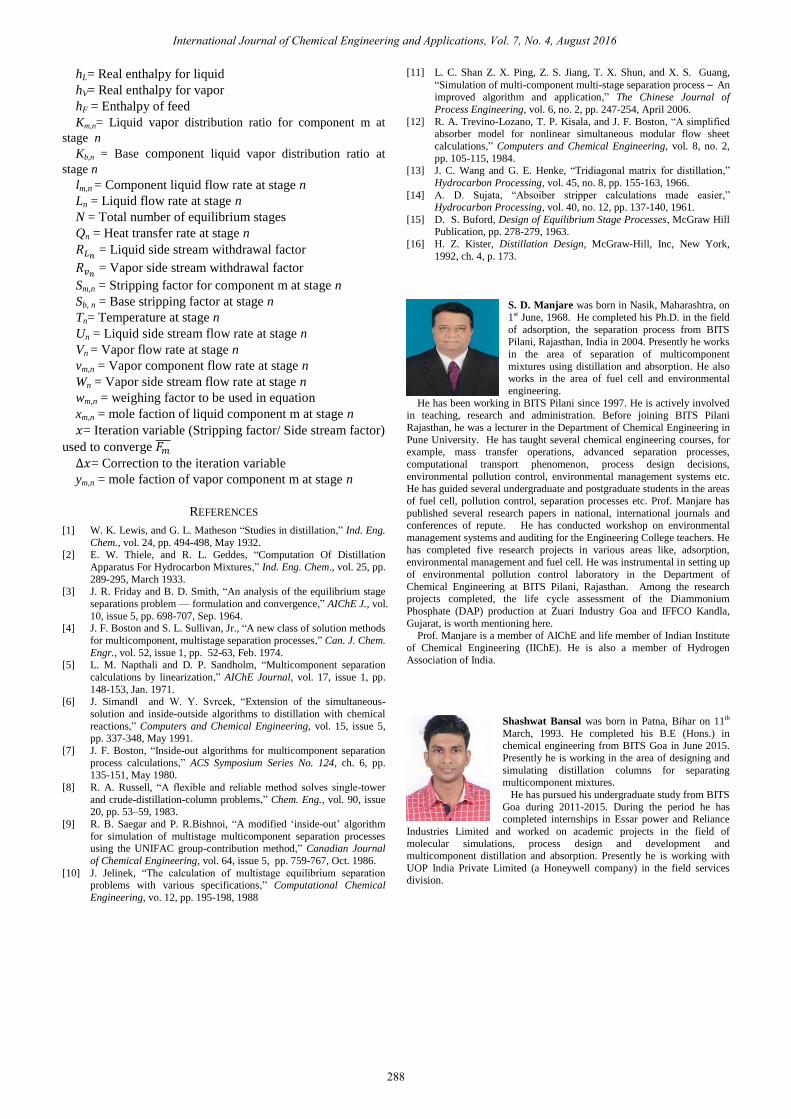
1) Comparison of distillate composition computed
using inside out with other methods
Fig. 13 presents comparison of distillation composition
computed using different methods. The distillate
composition obtained using these methods is almost same
except for component 3 and 5 where the composition
slightly deviates from composition obtained using other
methods.
Fig. 12. Liquid composition profile computed using inside out method.
Fig. 13. Comparison of distillate composition computed using different
methods.
* 1. Propane; 2. I-butane; 3- N-butane; 4. I-pentane; 5. N-pentane.
Fig. 14. Effect of feed location on distillate composition computed using
inside out method.
2) Effect of feed location on distillate and bottom
product composition
It is noted that feed location between stages 4 and 6 is
effective in achieving the desired split between LK and HK.
Beyond these stage numbers the separation is ineffective.
Therefore appropriate feed stage location can be selected
according to the composition desired.
Fig. 15. Effect of feed location on bottom product composition
computed using inside out method.
E. Condenser and Reboiler Duty Estimation
The condenser and reboiler duties for the column under
study have been estimated and are 2.55 × 10⁶ J/h and 3.53 ×
106 J/h respectively.
V. CONCLUSION
The Performance analysis of distillation column for
separation of multicomponent mixture has been carried out
using equilibrium based (inside out) method and the results
have been compared with the results obtained using Lewis
Matheson method, bubble point method and using an SCDS
column in CHEMCAD process simulator. From the
analysis, it is observed that the results obtained using the
inside out method are in close agreement with Lewis –
Matheson method and CHEMCAD. It is further observed
that inside out method is just as efficient as methods like
Lewis-Matheson for simple columns but is more robust for
complicated columns where Lewis-Matheson method fails
to converge. Also the simultaneous correction techniques
used by SCDS column in CHEMCAD has a greater
convergence time compared to inside out method. The
bubble point method failed to provide as accurate results as
the inside out method and hence it can be said that the inside
out is a better alternative to bubble point method. Finally it
is concluded that better convergence time, accurate results
and the ability to solve complicated columns make inside
out method the preferred choice for multicomponent
distillation operation.
NOMENCLATURE
αm,n = Relative volatility with respect to a base/reference
component
𝜖 = Damping factor
Fn = Feed flow rate at stage n
𝐹𝑚= Energy balance function/ Specification function to
be converged using Newton Raphson
fm,n = Component feed flow rate at stage n
International Journal of Chemical Engineering and Applications, Vol. 7, No. 4, August 2016
287
than-light key (LLK), and n-C5 is heavier than the heavy
key (HHK). Each of these four designations exhibits a
different type of composition profile curve as shown in Fig.
12. From the figure it is observed that liquid mole fraction
of the light key (n-C4) decreases linearly and continuously
from the top of the column to the bottom.
The inverse occurs for the heavy key (i-C5). Mole
fractions of C3 (LLK) are almost constant over the rectifying
section except near the top. Below the feed zone, C3 and i-
C4 rapidly disappears from liquid stream. Similarly the
concentration of n-C5, the HHK component increase from
top to bottom.
The Fig. 14 and Fig. 15 present the variation of LK and
HK concentrations in distillate and residue respectively with
the changes in feed stage location.
hL= Real enthalpy for liquid
hV= Real enthalpy for vapor
hF = Enthalpy of feed
Km,n= Liquid vapor distribution ratio for component m at
stage n
Kb,n = Base component liquid vapor distribution ratio at
stage n
lm,n = Component liquid flow rate at stage n
Ln = Liquid flow rate at stage n
N = Total number of equilibrium stages
Qn = Heat transfer rate at stage n
𝑅𝐿𝑛 = Liquid side stream withdrawal factor
𝑅𝑣𝑛 = Vapor side stream withdrawal factor
Sm,n = Stripping factor for component m at stage n
Sb, n = Base stripping factor at stage n
Tn= Temperature at stage n
Un = Liquid side stream flow rate at stage n
Vn = Vapor flow rate at stage n
vm,n = Vapor component flow rate at stage n
Wn = Vapor side stream flow rate at stage n
wm,n = weighing factor to be used in equation
xm,n = mole faction of liquid component m at stage n
𝑥= Iteration variable (Stripping factor/ Side stream factor)
used to converge 𝐹𝑚̅̅̅̅
∆𝑥= Correction to the iteration variable
ym,n = mole faction of vapor component m at stage n
REFERENCES
[1] W. K. Lewis, and G. L. Matheson “Studies in distillation,” Ind. Eng.
Chem., vol. 24, pp. 494-498, May 1932.
[2] E. W. Thiele, and R. L. Geddes, “Computation Of Distillation
Apparatus For Hydrocarbon Mixtures,” Ind. Eng. Chem., vol. 25, pp.
289-295, March 1933. [3] J. R. Friday and B. D. Smith, “An analysis of the equilibrium stage
separations problem — formulation and convergence,” AIChE J., vol.
10, issue 5, pp. 698-707, Sep. 1964. [4] J. F. Boston and S. L. Sullivan, Jr., “A new class of solution methods
for multicomponent, multistage separation processes,” Can. J. Chem.
Engr., vol. 52, issue 1, pp. 52-63, Feb. 1974. [5] L. M. Napthali and D. P. Sandholm, “Multicomponent separation
calculations by linearization,” AIChE Journal, vol. 17, issue 1, pp.
148-153, Jan. 1971. [6] J. Simandl and W. Y. Svrcek, “Extension of the simultaneous-
solution and inside-outside algorithms to distillation with chemical
reactions,” Computers and Chemical Engineering, vol. 15, issue 5, pp. 337-348, May 1991.
[7] J. F. Boston, “Inside-out algorithms for multicomponent separation
process calculations,” ACS Symposium Series No. 124, ch. 6, pp.
135-151, May 1980.
[8] R. A. Russell, “A flexible and reliable method solves single-tower
and crude-distillation-column problems,” Chem. Eng., vol. 90, issue 20, pp. 53–59, 1983.
[9] R. B. Saegar and P. R.Bishnoi, “A modified ‘inside-out’ algorithm
for simulation of multistage multicomponent separation processes using the UNIFAC group-contribution method,” Canadian Journal
of Chemical Engineering, vol. 64, issue 5, pp. 759-767, Oct. 1986.
[10] J. Jelinek, “The calculation of multistage equilibrium separation problems with various specifications,” Computational Chemical
Engineering, vo. 12, pp. 195-198, 1988
[11] L. C. Shan Z. X. Ping, Z. S. Jiang, T. X. Shun, and X. S. Guang,
“Simulation of multi-component multi-stage separation process ⎯ An improved algorithm and application,” The Chinese Journal of
Process Engineering, vol. 6, no. 2, pp. 247-254, April 2006.
[12] R. A. Trevino-Lozano, T. P. Kisala, and J. F. Boston, “A simplified absorber model for nonlinear simultaneous modular flow sheet
calculations,” Computers and Chemical Engineering, vol. 8, no. 2,
pp. 105-115, 1984. [13] J. C. Wang and G. E. Henke, “Tridiagonal matrix for distillation,”
Hydrocarbon Processing, vol. 45, no. 8, pp. 155-163, 1966.
[14] A. D. Sujata, “Absoiber stripper calculations made easier,” Hydrocarbon Processing, vol. 40, no. 12, pp. 137-140, 1961.
[15] D. S. Buford, Design of Equilibrium Stage Processes, McGraw Hill Publication, pp. 278-279, 1963.
[16] H. Z. Kister, Distillation Design, McGraw-Hill, Inc, New York,
1992, ch. 4, p. 173.
Shashwat Bansal was born in Patna, Bihar on 11th
March, 1993. He completed his B.E (Hons.) in chemical engineering from BITS Goa in June 2015.
Presently he is working in the area of designing and
simulating distillation columns for separating multicomponent mixtures.
He has pursued his undergraduate study from BITS
Goa during 2011-2015. During the period he has completed internships in Essar power and Reliance
Industries Limited and worked on academic projects in the field of
molecular simulations, process design and development and multicomponent distillation and absorption. Presently he is working with
UOP India Private Limited (a Honeywell company) in the field services division.
International Journal of Chemical Engineering and Applications, Vol. 7, No. 4, August 2016
288
S. D. Manjare was born in Nasik, Maharashtra, on
1st June, 1968. He completed his Ph.D. in the field
of adsorption, the separation process from BITS Pilani, Rajasthan, India in 2004. Presently he works
in the area of separation of multicomponent
mixtures using distillation and absorption. He also works in the area of fuel cell and environmental
engineering.
He has been working in BITS Pilani since 1997. He is actively involved in teaching, research and administration. Before joining BITS Pilani
Rajasthan, he was a lecturer in the Department of Chemical Engineering in
Pune University. He has taught several chemical engineering courses, for example, mass transfer operations, advanced separation processes,
computational transport phenomenon, process design decisions,
environmental pollution control, environmental management systems etc. He has guided several undergraduate and postgraduate students in the areas
of fuel cell, pollution control, separation processes etc. Prof. Manjare has
published several research papers in national, international journals and conferences of repute. He has conducted workshop on environmental
management systems and auditing for the Engineering College teachers. He
has completed five research projects in various areas like, adsorption, environmental management and fuel cell. He was instrumental in setting up
of environmental pollution control laboratory in the Department of
Chemical Engineering at BITS Pilani, Rajasthan. Among the research projects completed, the life cycle assessment of the Diammonium
Phosphate (DAP) production at Zuari Industry Goa and IFFCO Kandla,
Gujarat, is worth mentioning here. Prof. Manjare is a member of AIChE and life member of Indian Institute
of Chemical Engineering (IIChE). He is also a member of Hydrogen
Association of India.