theoretical study of friction induced vibration in
TRANSCRIPT
Theoretical Study of Friction Induced
Vibration in Frictional Systems
Thesis submitted in accordance with the requirements of the University
of Liverpool for the degree of Doctor in Philosophy
By
Ningyu Liu
September 2020
To my family
I
Abstract
Friction induced vibration widely exists in mechanical systems One typical example
is the automobile brake noise that originates from the vibration of a brake system
induced by the frictional contact between the rotating rotor and stationary pads
However a thorough understanding of friction induced vibration in various
mechanical systems has not been achieved yet and it remains a challenging research
topic due to the immense complexity of this problem Therefore the aim of the present
thesis is to study the friction induced vibration in theoretical mechanical models in
order to provide deeper understanding about the causes the dynamic behaviours and
the suppression of the friction-induced-vibration problem
1 The dynamics of a mass-slider with in-plane and transverse springs and dampers in
frictional contact with a spinning flexible disc in three different situations of
spinning speed ie constant deceleration constant acceleration and constant speed
is studied The in-plane motion of the slider causes time-varying normal force and
bending moment on the disc which can be seen as moving loads to excite the
transverse vibration of the elastic disc The transverse vibration of the disc will in
turn influence the in-plane motion of the slider by affecting the magnitude of
friction force through the varying normal force Therefore the transverse vibration
and the in-plane vibration of the slider are coupled The numerical algorithm for
the transient dynamic analysis of the system involving three different states of
motion and non-smooth transitions among the states is proposed Numerical
simulation results show that distinct dynamic behaviours can be observed in the
three situations of disc speed and two kinds of particular characteristics of
differences are revealed The significant effects of decelerating and accelerating
disc rotation on the friction induced vibration of the system underlie the necessity
II
to take into account time-varying sliding velocity in the research of friction induced
vibration
2 The effects of tangential high-frequency harmonic excitation on the friction induced
vibration in multi-degree-of-freedom systems that are coupled in the tangential and
normal directions are theoretically investigated in which a minimal two-degree-
of-freedom system and a more complicated slider-on-disc system are considered
It is observed the tangential harmonic excitation with appropriate amplitude and
frequency suppresses the friction induced vibration in the systems The analytical
method to determine the ranges of the amplitude and frequency of the harmonic
excitation with which the friction-excited systems are stabilized is established To
verify the analytical results a great amount of computational effort is also made to
simulate the time responses of systems in various combinations of values of the
amplitude and frequency by which the parameter ranges where the friction induced
vibration is suppressed can also be obtained This research can provide theoretical
guidance for the suppression of friction induced vibration in real mechanical
systems by application of a tangential harmonic excitation
3 The friction induced vibration of a five-degree-of-freedom mass-on-oscillating-belt
model considering multiple types of nonlinearities is studied The first type of
nonlinearity in the system is the nonlinear contact stiffness the second is the non-
smooth behaviour including stick slip and separation and the third is the
geometrical nonlinearity brought about by the moving-load feature of the mass
slider on the rigid belt Both the linear stability of the system and the nonlinear
steady-state responses are investigated and rich dynamic behaviours of the system
are revealed The results of numerical study indicate the necessity of the transient
dynamic analysis in the study of friction-induced-vibration problems as the linear
stability analysis fails to detect the occurrence of self-excited vibration when two
stable solutions coexist in the system Additionally the significant effects of each
type of nonlinearity on the linear stability and nonlinear steady-state responses of
the system are discovered which underlie the necessity to take multiple types of
nonlinearities into account in the research of friction induced vibration The similar
study is also conducted on a continuous slider-on-disc model
III
4 A new pin-on-disc system with an L-mechanism to adjust the normal force is
proposed and the friction induced stick-slip vibration of the system is theoretically
studied The Coulomb law of friction is utilized to model the friction force between
the pin and disc It is observed that the system is bi-stable at low disc speed and
high normal preload ie there is coexistence of a stable pure sliding solution and
a stable stick-slip limit cycle for the pin and the variable normal force can lead to
the bifurcation and even chaotic behaviours of the responses in the system Then
the effect of non-uniform friction interface in which a sector of disc has a different
set of friction property on the stick-slip vibration of the system is studied It is
found that with appropriate friction coefficients on the sector and an appropriate
span angle of the sector the range of disc speed and normal preload at which the
stick-slip limit cycle exists will be greatly diminished Therefore a potential
approach to suppress the friction induced stick-slip vibration is provided
IV
Acknowledgements
I would like to pay my deepest and most sincere gratitude to my supervisor Professor
Huajiang Ouyang who is a professional insightful and respectable scholar with caring
character He not only provided me with valuable guidance and help for me to advance
my project and get through struggling times but also instilled into me the passion and
rigorous attitude towards research in the past four years
Many thanks to my fellow PhD students and academic staff in the Dynamics and
Control Group at the University of Liverpool for their advice and help in my research
I would also love to thank my family and friends for their mental support and
encouragement which helped me to settle in foreign environment and conduct my
research cheerfully
The joint scholarship of University of Liverpool and China Scholarship Council is also
gratefully acknowledged which provides me with financial support for my research
and living expenses in the past four years
Last but not the least I would like to thank the city of Liverpool which is such a
vibrant and diverse city I am very happy to spend four years studying and living here
V
List of Publications
Journal papers
1 N Liu H Ouyang Friction-induced vibration of a slider on an elastic disc spinning
at variable speeds Nonlinear Dynamics 98(1) (2019) 39-60
2 N Liu H Ouyang Suppression of friction-induced-vibration in MDoF systems
using tangential harmonic excitation Meccanica 55 (2020) 1525ndash1542
3 N Liu H Ouyang Friction-induced vibration considering multiple types of
nonlinearities Nonlinear Dynamics (2020) httpsdoiorg101007s11071-020-
06055-x
Conference papers
1 N Liu H Ouyang Suppression of friction induced vibration of a pin-on-disc
system by alternate friction interfaces ICSV27 Annual Congress of International
Institute of Acoustics and Vibration (IIAV) Prague(The conference is postponed
to July 2021)
VI
Contents of Thesis
AbstractI
AcknowledgementsIV
List of PublicationsV
Contents of ThesisVI
List of FiguresXI
List of TablesXXIII
NomenclatureXXIV
Chapter 1 Introduction1
11 Background and motivations1
12 Aim and objectives2
13 Original contributions3
14 Outline of the thesis4
Chapter 2 Literature review7
21 Mechanisms for generation of friction induced vibration7
211 Stick-slip oscillation7
212 Sprag-slip instability9
213 Negative gradient in friction coefficientndashrelative velocity relationship10
214 Mode-coupling instability10
215 Additional Mechanisms11
VII
22 Friction force models for dynamic analysis12
221 lsquoStaticrsquo friction models12
222 lsquoDynamicrsquo friction models16
23 Investigation of friction induced vibration in mechanical
models17
231 Lumped models18
232 Continuous models21
233 Finite element models22
24 Dynamics of spinning disc in contact with stationary parts24
25 Experimental investigations on the friction induced vibration26
26 Conclusion29
Chapter 3 Basic theories and analytical methods of friction induced
vibration30
31 Principal mechanisms of friction induced vibration30
311 Negative friction-velocity slope30
312 Stick-slip oscillation31
313 Mode-coupling instability37
32 Analytical methods of friction induced vibration42
321 Complex eigenvalue analysis42
322 Transient dynamic analysis44
33 Basic theories of the vibration of elastic thin plates47
331 Free vibration of elastic thin plates47
332 Natural frequencies and mode shapes of an annular plate with clamped inner
boundary and free outer boundary48
VIII
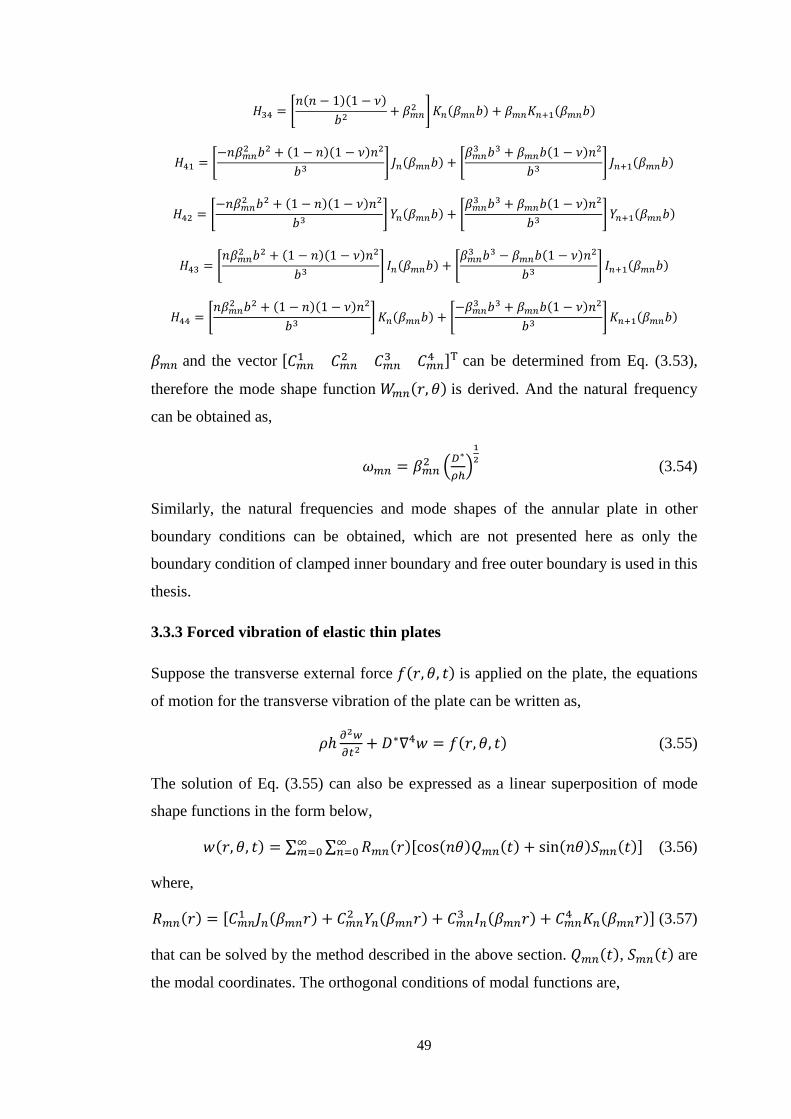
333 Forced vibration of elastic thin plates49
Chapter 4 Friction induced vibration of a slider on an elastic disc
spinning at time-varying speeds51
41 Introduction51
42 Model description and theoretical analysis53
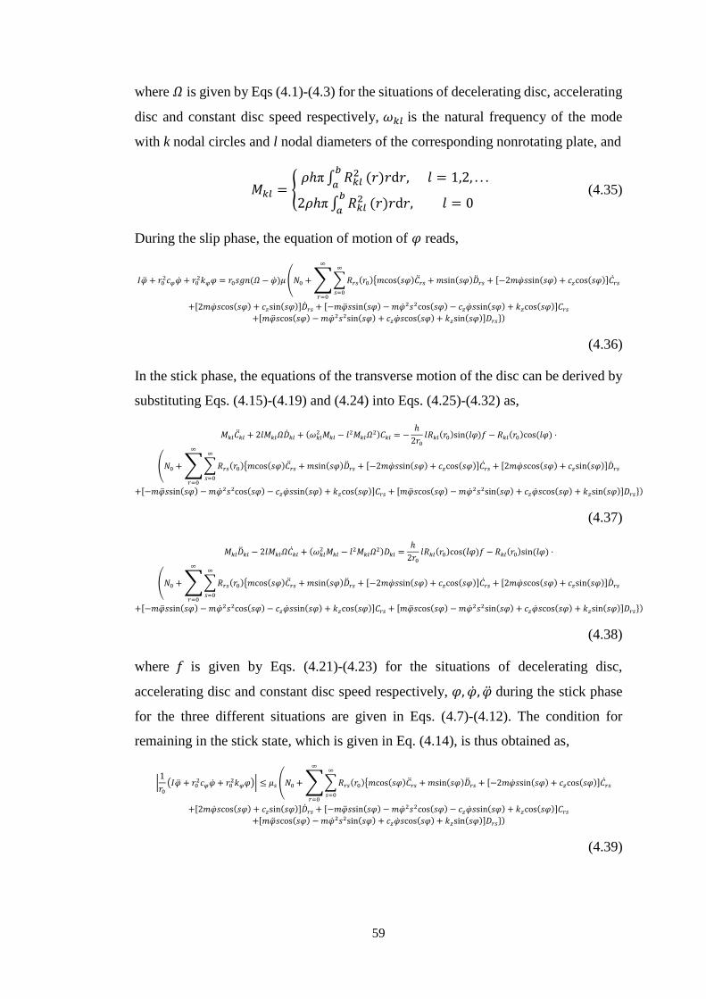
421 Circumferential stick-slip vibration of the slider55
422 Transverse vibration of the disc56
423 Coupled in-plane and out-of-plane vibration58
424 Separation and re-contact60
43 Numerical simulation and analysis62
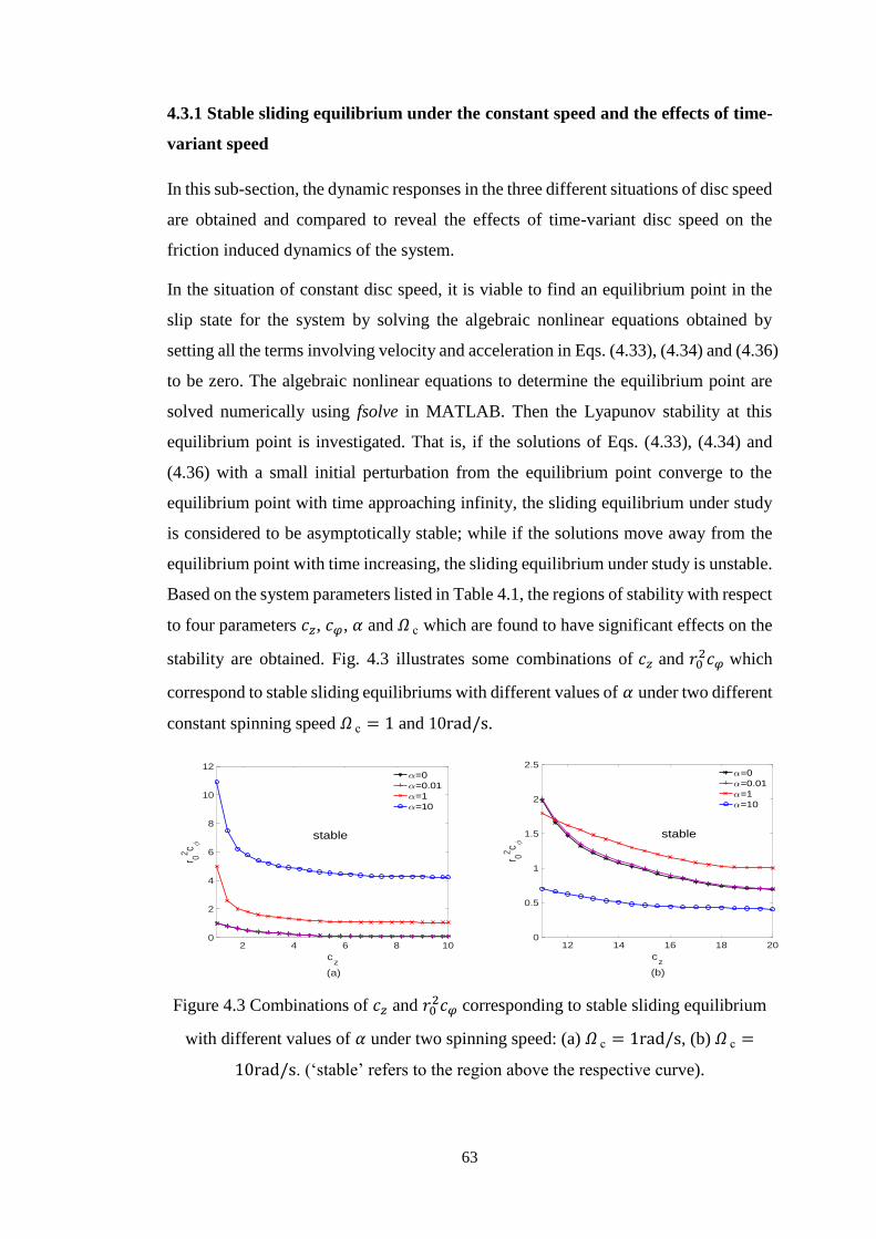
431 Stable sliding equilibrium under the constant speed and the effects of
time-variant speed63
432 Non-stationary dynamic behaviour under the time-variant disc speed66
433 Impact during vibration74
44 Conclusions75
Chapter 5 Suppression of friction induced vibration in MDoF
systems using tangential harmonic excitation77
51 Introduction77
52 A minimal 2-DoF frictional system 79
53 Slider-on-disc system82
54 Numerical study88
541 Numerical study of the 2-DoF frictional system88
542 Numerical study of the slider-on-disc system91
55 Conclusions96
IX
Chapter 6 Friction induced vibration considering multiple types of
nonlinearities97
61 Introduction97
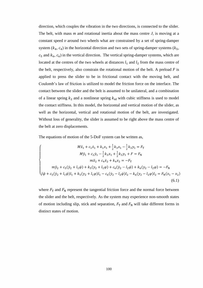
62 The mechanical model and dynamic equations99
63 Linear stability analysis and transient dynamic analysis103
631 Linear stability analysis of the 5-DoF model103
632 Transient dynamic analysis105
64 Numerical study of the 5-DoF model105
641 Stability analysis105
642 Nonlinear steady-state responses109
65 The effects of multiple nonlinearities on the dynamics of slider-on-
disc model118
651 Linear stability analysis of the slider-on-disc model122
652 Nonlinear steady-state responses of the slider-on-disc model126
66 Conclusions134
Chapter 7 Friction induced vibration of a pin-on-disc system
considering non-uniform friction interface136
71 Introduction137
72 Model description and dynamic equations138
73 Numerical study of system dynamics under the uniform friction
interface141
74 Numerical study of system dynamics under the non-uniform friction
interface145
75 Conclusions150
X
Chapter 8 Conclusions and outlook151
81 Conclusions151
82 Outlook154
References156
XI
List of Figures
Figure 21 Friction force versus relative velocity for 1D case (a) Coulomb friction
model (b) Coulomb model with larger static friction force (c) Coulomb
friction with viscous friction (d) Model with Stribeck
effect 13
Figure 22 Smooth functions to approximate the Coulomb friction model for 1D
case 14
Figure 23 Hysteretic behaviour of friction force 15
Figure 31 A single-degree-of-freedom friction oscillator 31
Figure 32 A single-degree-of-freedom mass-on-moving-belt model 32
Figure 33 The phase-plane plots of single-degree-of-freedom friction oscillator
with various initial conditions 33
Figure 34 A single-degree-of-freedom mass-on-moving-belt model with harmonic
external excitation 33
Figure 35 The phase-plane plots and frequency spectrums with different excitation
frequencies (a) and (d) 120596 = 085 (b) and (e) 120596 = 12 (c) and (f) 120596 =
05 34
Figure 36 The bifurcation behaviour of the system response dependent on the
excitation frequency under the Coulombrsquos law 35
Figure 37 The bifurcation behaviour of the system response dependent on the
excitation frequency under the friction law with Stribeck effect 35
Figure 38 A two-degree-of-freedom mass-on-moving-belt model 35
Figure 39 The phase-plane plots and frequency spectrums with damping ratios D
(a) and (d) 119863 = 03 (b) and (e) 119863 = 02 (c) and (f) 119863 = 01 37
XII
Figure 310 The bifurcation behaviour of the system responses of the two-degree-of-
freedom model dependent on the damping ratio 37
Figure 311 A two-degree-of-freedom friction model 38
Figure 312 The eigenvalues of the system as a function of 120583 39
Figure 313 The time histories of the dynamic responses (a) 120583 = 41 (b) 120583 =
43 39
Figure 314 The eigenvalues of the system with proportional damping as a function
of 120583 40
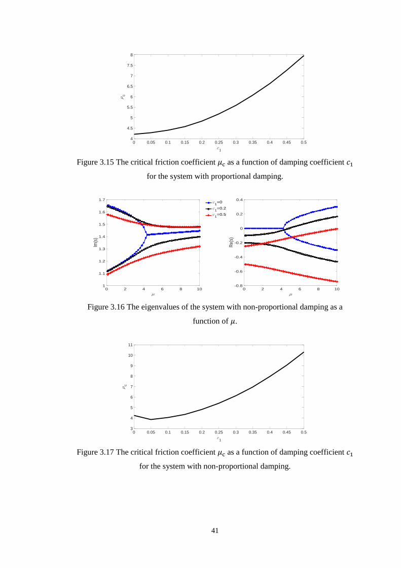
Figure 315 The critical friction coefficient 120583c as a function of damping coefficient 1198881
for the system with proportional damping 41
Figure 316 The eigenvalues of the system with non-proportional damping as a
function of 120583 41
Figure 317 The critical friction coefficient 120583c as a function of damping coefficient 1198881
for the system with non-proportional damping 41
Figure 318 The flowchart of the computation procedure for the time histories of the
non-smooth friction induced vibration 46
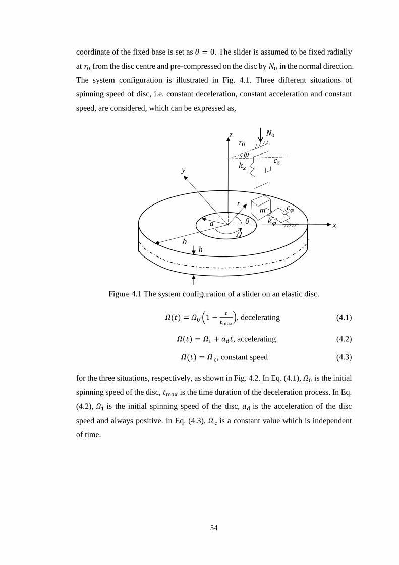
Figure 41 The system configuration of a slider on an elastic disc54
Figure 42 The three situations of spinning speed of the disc 55
Figure 43 Combinations of 119888119911 and 11990302119888120593 corresponding to stable sliding equilibrium
with different values of 120572 under two spinning speed (a) 120570 c = 1rads
(b) 120570 c = 10rads 63
Figure 44 The system dynamic responses under the constant disc speed (a) the
spinning speed of disc (b) the circumferential velocity of the slider (c)
the transverse displacement of a specific point on the disc at 119903 = 1199030 and
120579 = 0 (119888119911 = 11 N sdot sm 11990302119888120593 = 1 N sdot m sdot srad 120572=10 120570 c = 10rad
s) 64
XIII
Figure 45 The system dynamic responses under the decelerating disc (a) the
spinning speed of disc (b) the circumferential velocity of the slider (c)
the transverse displacement of a specific point on the disc at 119903 = 1199030 and
120579 = 0 (119888119911 = 11 N sdot sm 11990302119888120593 = 1 N sdot m sdot srad 120572=10 120570 0 = 10rad
s 119905max = 20s) 65
Figure 46 The system dynamic responses under the constant disc speed (a) the
spinning speed of disc (b) the circumferential velocity of the slider (c)
the transverse displacement of disc at (1199030 0)(119888119911 = 1N sdot sm 11990302119888120593 =
2 N sdot m sdot srad 120572=0 120570 c = 1rads) 65
Figure 47 The system dynamic responses under the accelerating disc (a) the
spinning speed of disc (b) the circumferential velocity of the slider (c)
the transverse displacement of disc at (1199030 0) (119888119911 = 1N sdot sm 11990302119888120593 =
2 N sdot m sdot srad 120572=0 120570 1 = 1rads 119888 = 3rads2) 66
Figure 48 The time history of the circumferential angular velocity of the slider and
time-frequency plot of the circumferential angular displacement of the
slider under the constant disc speed (a) the time history of the
circumferential angular velocity (b) the time-frequency plot of the
circumferential angular displacement(119888119911 = 01N sdot sm 11990302119888120593 = 01 N sdot
m sdot srad 120572=1 120570 c = 2πrads) 66
Figure 49 The time history and time-frequency plot of the transverse displacement
of the disc at 119903 = 1199030 and 120579 = 1rad under the constant disc speed (a) the
time history (b) the frequency spectrum plot 67
Figure 410 The time history of the circumferential angular velocity of the slider and
time-frequency plot of the circumferential angular displacement of the
slider under the decelerating disc (a) the time history of the
circumferential angular velocity (b) the time-frequency plot of the
circumferential angular displacement(119888119911 = 01N sdot sm 11990302119888120593 = 01 N sdot
m sdot srad 120572=1 120570 0 = 2πrads 119905max = 35s) 67
XIV
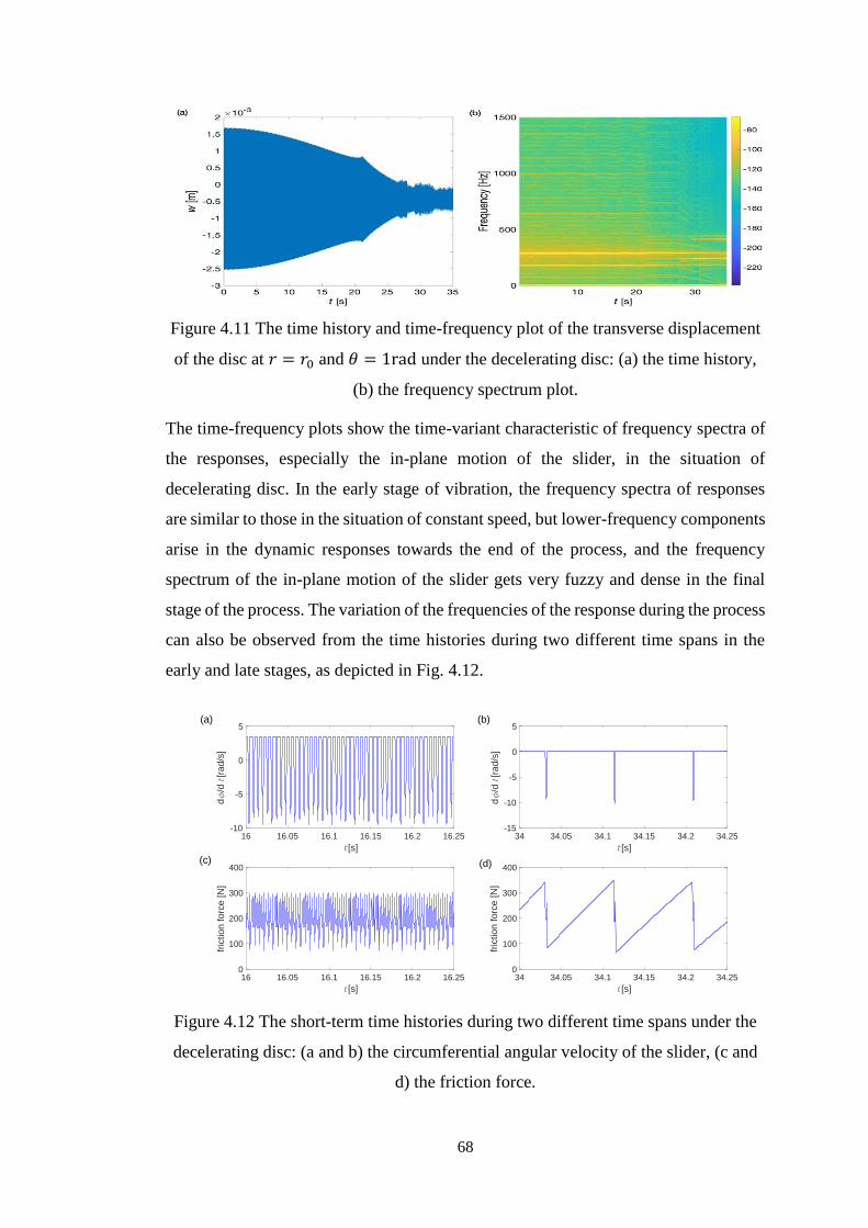
Figure 411 The time history and time-frequency plot of the transverse displacement
of the disc at 119903 = 1199030 and 120579 = 1rad under the decelerating disc (a) the
time history (b) the frequency spectrum plot 68
Figure 412 The short-term time histories during two different time spans under the
decelerating disc (a and b) the circumferential angular velocity of the
slider (c and d) the friction force 68
Figure 413 The time history of the circumferential angular velocity of the slider and
time-frequency plot of the circumferential angular displacement of the
slider under the constant disc speed (a) the time history of the
circumferential angular velocity (b) the time-frequency plot of the
circumferential angular displacement( 119888119911 = 2N sdot sm 11990302119888120593 = 05 N sdot
m sdot srad 120572=1 120570 c = 2πrads) 70
Figure 414 The time history and time-frequency plot of the transverse displacement
of the disc at 119903 = 1199030 and 120579 = 1rad under the constant disc speed (a) the
time history (b) the frequency spectrum plot 70
Figure 415 The time history of the circumferential angular velocity of the slider and
time-frequency plot of the circumferential angular displacement of the
slider under the decelerating disc (a) the time history of the
circumferential angular velocity (b) the time-frequency plot of the
circumferential angular displacement( 119888119911 = 2N sdot sm 11990302119888120593 = 05 N sdot
m sdot srad 120572=1 120570 0 = 2πrads 119905max = 35s)70
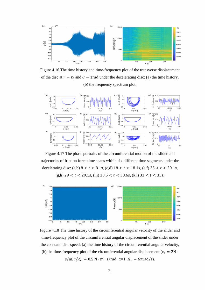
Figure 416 The time history and time-frequency plot of the transverse displacement
of the disc at 119903 = 1199030 and 120579 = 1rad under the decelerating disc (a) the
time history (b) the frequency spectrum plot 71
Figure 417 The phase portraits of the circumferential motion of the slider and
trajectories of friction force during time spans within six different time
segments under the decelerating disc (ab) 8 lt 119905 lt 81s (cd) 18 lt 119905 lt
181s (ef) 25 lt 119905 lt 201s (gh) 29 lt 119905 lt 291s (ij) 305 lt 119905 lt
306s (kl) 33 lt 119905 lt 35s 71
XV
Figure 418 The time history of the circumferential angular velocity of the slider and
time-frequency plot of the circumferential angular displacement of the
slider under the constant disc speed (a) the time history of the
circumferential angular velocity (b) the time-frequency plot of the
circumferential angular displacement( 119888119911 = 2N sdot sm 11990302119888120593 = 05 N sdot
m sdot srad 120572=1 120570 c = 6πrads) 71
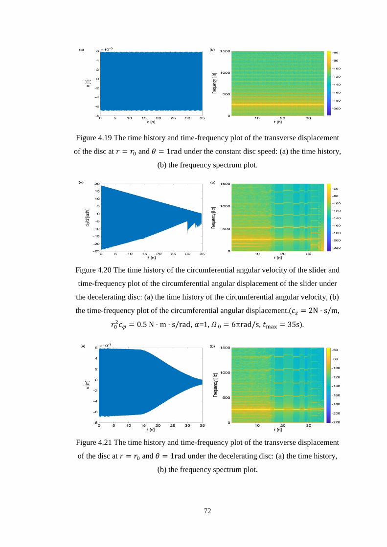
Figure 419 The time history and time-frequency plot of the transverse displacement
of the disc at 119903 = 1199030 and 120579 = 1rad under the constant disc speed (a) the
time history (b) the frequency spectrum plot 72
Figure 420 The time history of the circumferential angular velocity of the slider and
time-frequency plot of the circumferential angular displacement of the
slider under the decelerating disc (a) the time history of the
circumferential angular velocity (b) the time-frequency plot of the
circumferential angular displacement( 119888119911 = 2N sdot sm 11990302119888120593 = 05 N sdot
m sdot srad 120572=1 120570 0 = 6πrads 119905max = 35s) 72
Figure 421 The time history and time-frequency plot of the transverse displacement
of the disc at 119903 = 1199030 and 120579 = 1rad under the decelerating disc (a) the
time history (b) the frequency spectrum plot 72
Figure 422 The variation of normal force with time in the situation of accelerating
disc in the two cases (a) 119888119911 = 01N sdot sm 11990302119888120593 = 01 N sdot m sdot srad
120572=1 120570 1 = 2πrads 119888 = 02rads2 (b) 119888119911 = 2N sdot sm 11990302119888120593 = 05 N sdot
m sdot srad 120572=1 120570 1 = 2πrads 119888 = 02rads2 73
Figure 423 The time histories and time-frequency plots of the dynamic responses
under the accelerating disc (a) (b) the in-plane motion of the slider (c)
(d) the transverse motion of the disc (119888119911 = 01N sdot sm 11990302119888120593 = 01 N sdot
m sdot srad 120572=1 120570 1 = 2πrads 119888 = 02rads2) 73
Figure 424 The time histories and time-frequency plots of the dynamic responses
under the accelerating disc (a) (b) the in-plane motion of the slider (c)
(d) the transverse motion of the disc (119888119911 = 2N sdot sm 11990302119888120593 = 05 N sdot m sdot
srad 120572=1 120570 1 = 2πrads 119888 = 02rads2) 74
XVI
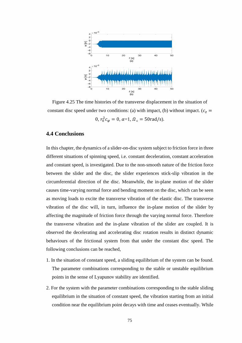
Figure 425 The time histories of the transverse displacement in the situation of
constant disc speed under two conditions (a) with impact (b) without
impact (119888119911 = 0 11990302119888120593 = 0 120572=1 120570 c = 50rads) 75
Figure 51 Two-degree-of-freedom frictional system 79
Figure 52 The slider-on-disc system 83
Figure 53 The eigenvalue of the Jacobian matrix of the original system as a function
of 120583k 89
Figure 54 The time histories of tangential and normal displacements of the original
system when 120583k is larger than its critical value (a) (b) 120583k = 04 (c) (d)
120583k = 07 89
Figure 55 The dynamic responses of the system after application of the harmonic
excitation with amplitude 119860b = 35 and frequency ratio 119877 =120596
1205961= 20 (a)
(b) 120583k = 04 (c) (d) 120583k = 07 (The belt velocity is 03) 90
Figure 56 The range of the amplitude and frequency of the harmonic excitation to
stabilize the system obtained from both the analytical method and the
extensive time response simulations (119907 = 03 the parameter range to
stabilize the system is above the corresponding curve) 91
Figure 57 The range of the amplitude and frequency of the harmonic excitation to
stabilize the system under three different values of belt velocity (120583k =
07 the parameter range to stabilize the system is above the
corresponding curve) 91
Figure 58 Region of instability of normal preload versus disc speed in three cases
of friction coefficients (a) 120583s = 1 120572 = 0 (b) 120583s = 15 120583k = 12 120572 =
1 (c) 120583s = 225 120583k = 2 120572 = 1 93
XVII
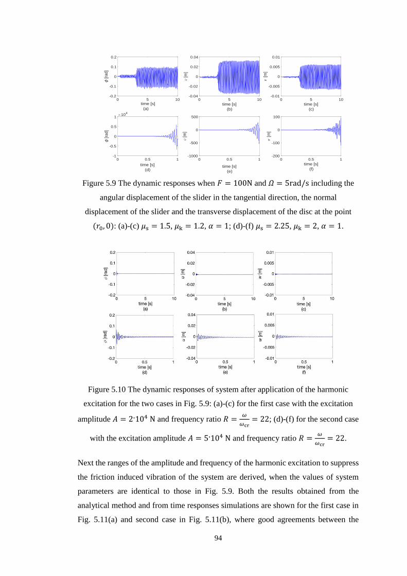
Figure 59 The dynamic responses when 119865 = 100N and 120570 = 5rads including the
angular displacement of the slider in the tangential direction the normal
displacement of the slider and the transverse displacement of the disc at
the point (1199030 0) (a)-(c) 120583s = 15 120583k = 12 120572 = 1 (d)-(f) 120583s = 225
120583k = 2 120572 = 1 94
Figure 510 The dynamic responses of system after application of the harmonic
excitation for the two cases in Figure 59 (a)-(c) for the first case with
the excitation amplitude 119860 = 2104 N and frequency ratio 119877 =120596
120596cr=
22 (d)-(f) for the second case with the excitation amplitude 119860 = 5104 N
and frequency ratio 119877 =120596
120596cr= 22 94
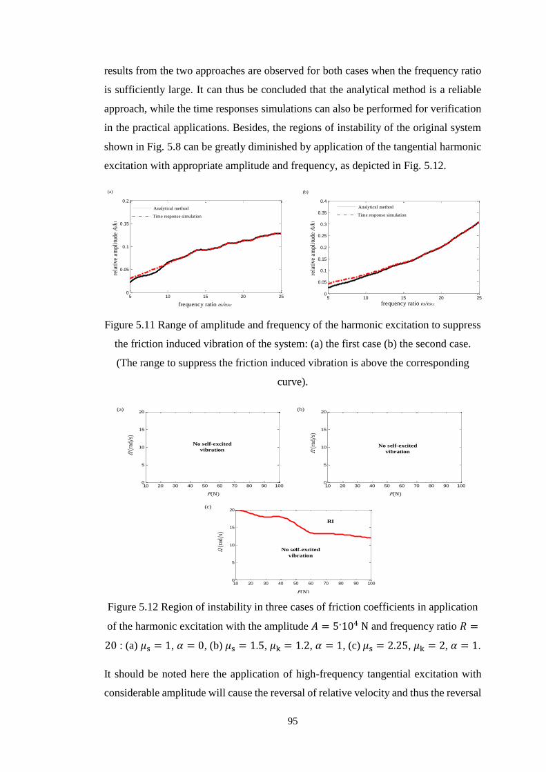
Figure 511 Range of amplitude and frequency of the harmonic excitation to suppress
the friction induced vibration of the system (a) the first case (b) the
second case (The range to suppress the friction induced vibration is
above the corresponding curve) 95
Figure 512 Region of instability in three cases of friction coefficients in application
of the harmonic excitation with the amplitude 119860 = 5104 N and
frequency ratio 119877 = 20 (a) 120583s = 1 120572 = 0 (b) 120583s = 15 120583k = 12 120572 =
1 (c) 120583s = 225 120583k = 2 120572 = 1 95
Figure 61
The model of the 5-DoF frictional system 101
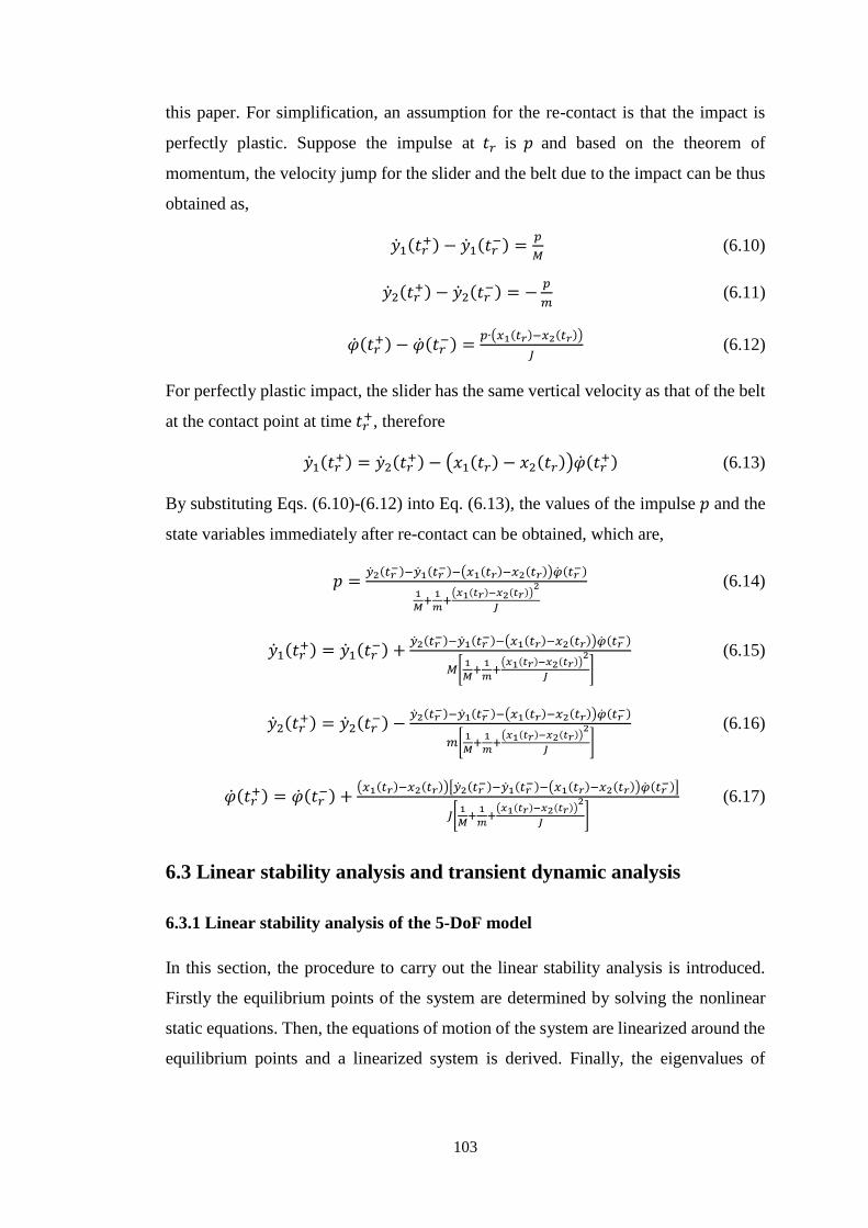
Figure 62 Stability analysis of the 5-DoF frictional model with different nonlinear
contact stiffness 119896nl when the preload 119865 = 100N (a) frequencies and (b)
growth rates 106
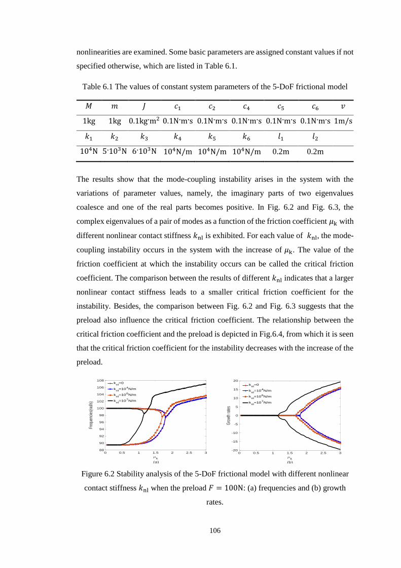
Figure 63 Stability analysis of the 5-DoF frictional model with different nonlinear
contact stiffness 119896nl when the preload 119865 = 1000N (a) frequencies and
(b) growth rates 107
Figure 64 The critical friction coefficient 120583k for the instability of the 5-DoF
frictional model as a function of the preload 119865 107
XVIII
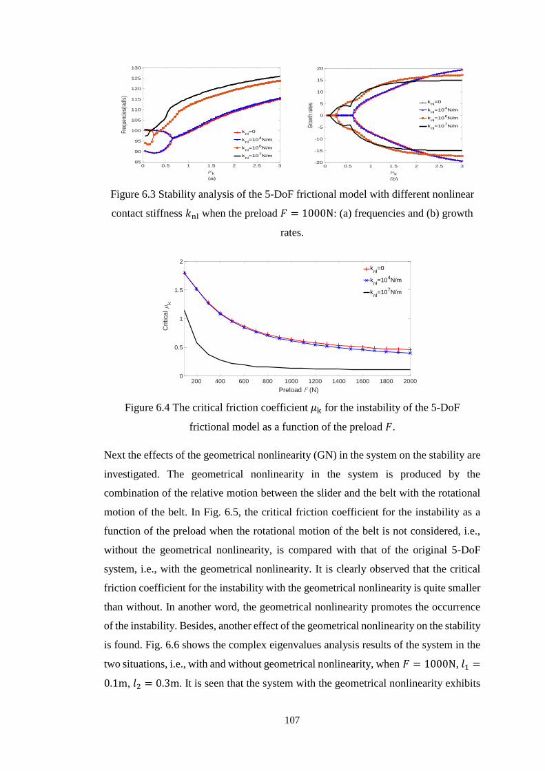
Figure 65 The effect of the geometrical nonlinearity (GN) on the critical friction
coefficient 120583k for the instability of the 5-DoF frictional model 108
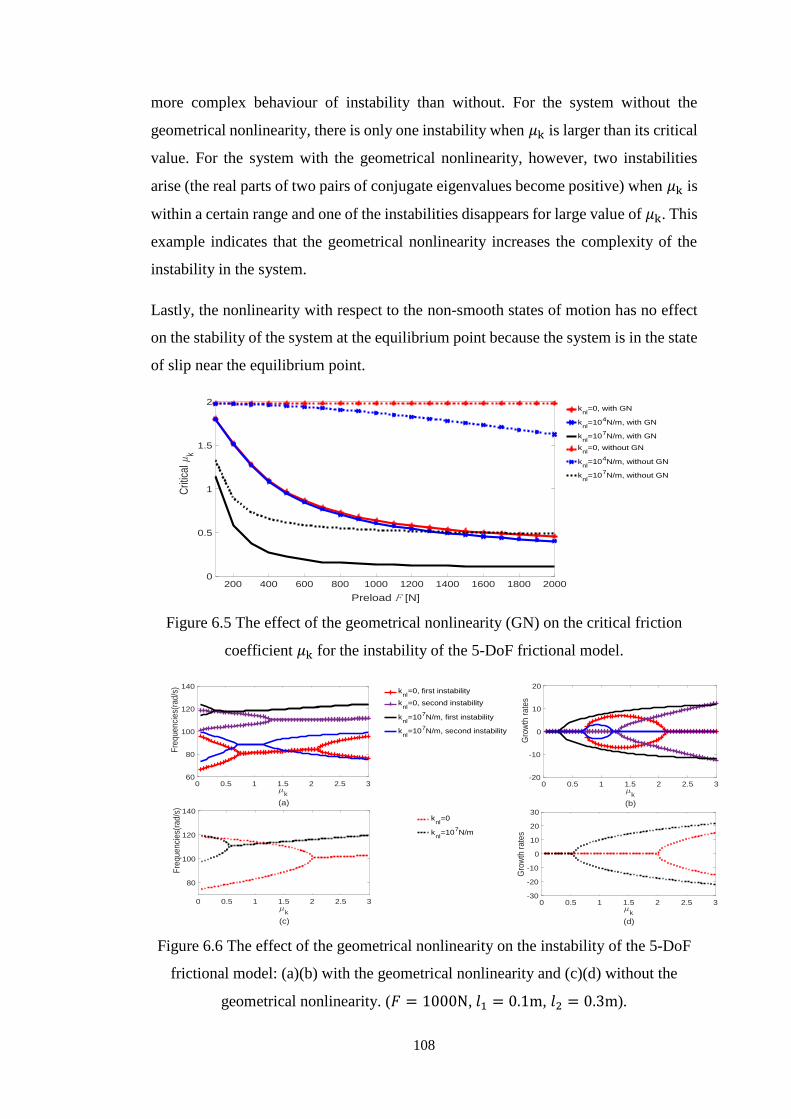
Figure 66 The effect of the geometrical nonlinearity on the system instability of the
5-DoF frictional mode (a)(b) with the geometrical nonlinearity and (c)(d)
without the geometrical nonlinearity (119865 = 1000N 1198971 = 01m 1198972 =
03m) 108
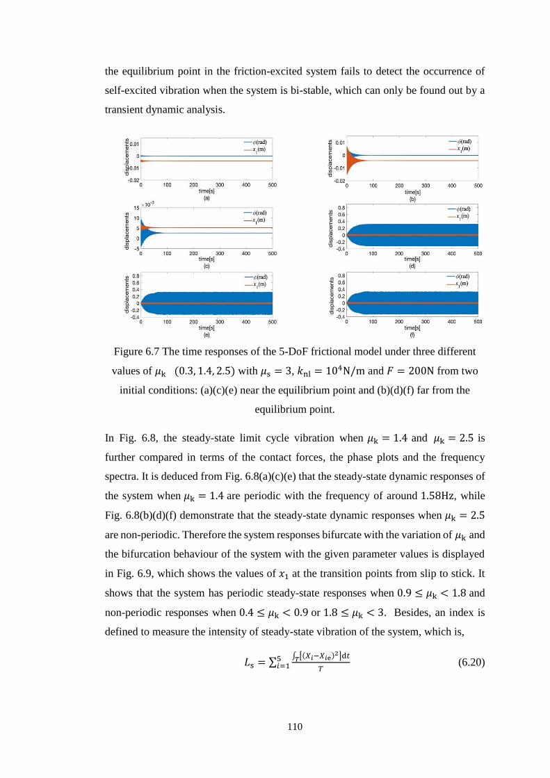
Figure 67 The time responses of the 5-DoF frictional model under three different
values of 120583k (03 14 25) with 120583s = 3 119896nl = 104Nm and 119865 = 200N
from two initial conditions (a)(c)(e) near the equilibrium point and
(b)(d)(f) far from the equilibrium point 110
Figure 68 The steady-state limit cycle vibration of the 5-DoF frictional model in
terms of the contact forces the phase plots and the frequency spectra
(a)(c)(e) 120583k = 14 and (b)(d)(f) 120583k = 25 111
Figure 69 The bifurcation behaviour of the steady-state limit cycle vibration of the
5-DoF frictional model 111
Figure 610 Index 119871s as a function of 120583k of the 5-DoF frictional model 112
Fig 611 The bifurcation behaviours of the steady-state limit cycle vibration of the
5-DoF frictional model with different values of 119896nl (a) 119896nl = 0 and (b)
119896nl = 107Nm 113
Figure 612 Index 119871s as a function of 120583k for the 5-DoF frictional model with different
values of 119896nl 113
Figure 613 The bifurcation behaviours of the steady-state limit cycle vibration (a-c)
and phase-plane plots when 120583k = 2 (d-f) for the 5-DoF frictional model
without the geometrical nonlinearity (a)(d) 119896nl = 0 (b)(e) 119896nl =
104Nm and (c)(f) 119896nl = 107Nm 114
Figure 614 Index 119871s as a function of 120583k for the 5-DoF frictional model without the
geometrical nonlinearity 115
XIX
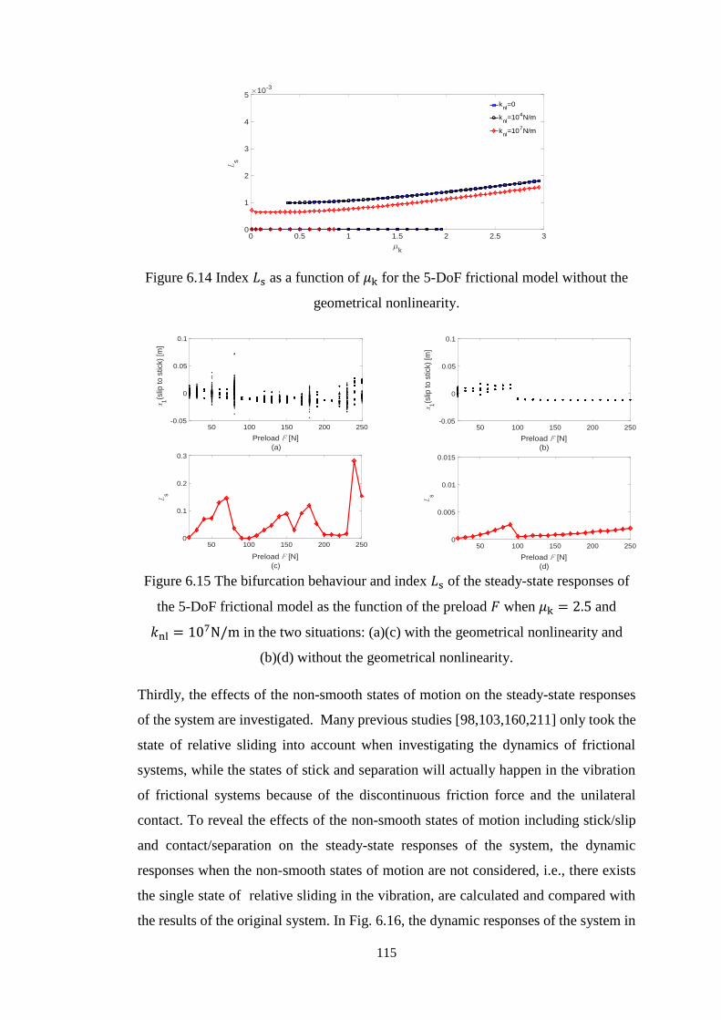
Figure 615 The bifurcation behaviour and index 119871s of the steady-state responses of
the 5-DoF frictional model as the function of the preload 119865 when 120583k =
25 and 119896nl = 107Nm in the two situations (a)(c) with the geometrical
nonlinearity and (b)(d) without the geometrical nonlinearity 115
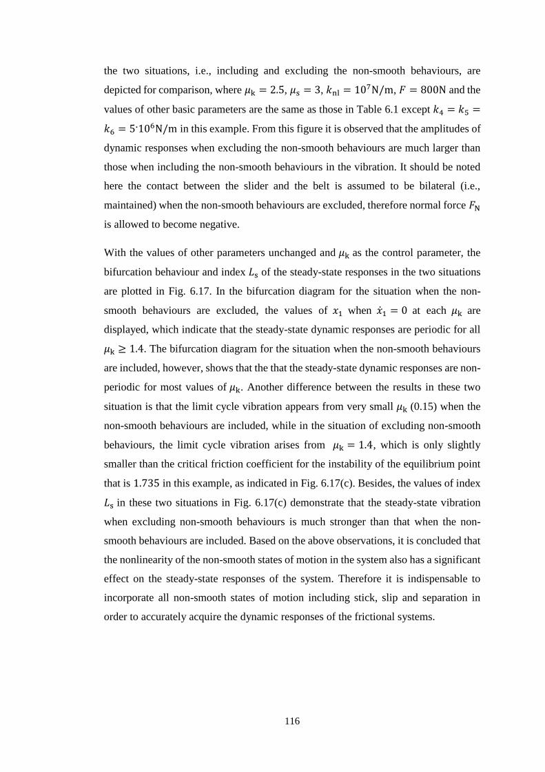
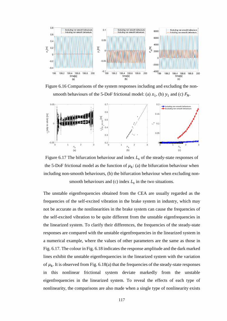
Figure 616 Comparisons of the system responses including and excluding the non-
smooth behaviours of the 5-DoF frictional model (a) 1199091 (b) 1199101 and (c)
119865N 117
Figure 617 The bifurcation behaviour and index 119871s of the steady-state responses of
the 5-DoF frictional model as the function of 120583k (a) the bifurcation
behaviour when including non-smooth behaviours (b) the bifurcation
behaviour when excluding non-smooth behaviours and (c) index 119871s in the
two situations 117
Figure 618 The frequencies of the steady-state responses of the system and unstable
eigenfrequency of the linearized system of the 5-DoF frictional model
(a) with all three types of nonlinearities (b) with the single nonlinearity
of contact stiffness (c) with the single geometrical nonlinearity and (d)
with the single nonlinearity of non-smooth behaviours 118
Figure 619 The slider-on-disc model with nonlinearities 119
Figure 620 The real parts of the complex eigenvalues of the linearized system of the
slider-on-disc model as a function of 120583k with different values of
119896nl 124
Figure 6 21 The imaginary parts of the complex eigenvalues of the linearized system
of the slider-on-disc model as a function of 120583k with different values of
119896nl 124
Figure 622 Stability analysis of the slider-on-disc model without the geometrical
nonlinearity as a function of 120583k with different values of 119896nl (a)
frequencies and (b) growth rates 125
XX
Figure 623 The critical friction coefficients for the slider-on-disc model with and
without the geometrical nonlinearity (GN) as functions of the
preload 126
Figure 624 The time histories of the tangential motion of the slider and the transverse
displacement of a specific point (119903 = 1199030 120579 = 1) on the disc under 120583k =
03 with 120583s = 3 119896nl = 106Nm and 119865 = 1000N from two initial
conditions (a)(b) near the equilibrium point and (c)(d) far from the
equilibrium point 127
Figure 625 The time histories of the tangential motion of the slider and the transverse
displacement of a specific point (119903 = 1199030 120579 = 1) on the disc under 120583k =
22 with 120583s = 3 119896nl = 106Nm and 119865 = 1000N from two initial
conditions (a)(b) near the equilibrium point and (c)(d) far from the
equilibrium point 127
Figure 626 Index 119871s as a function of 120583k of the slider-on-disc model 128
Figure 627 The bifurcation behaviour of the steady-state response of the slider-
on-disc model dependent on 120583k 128
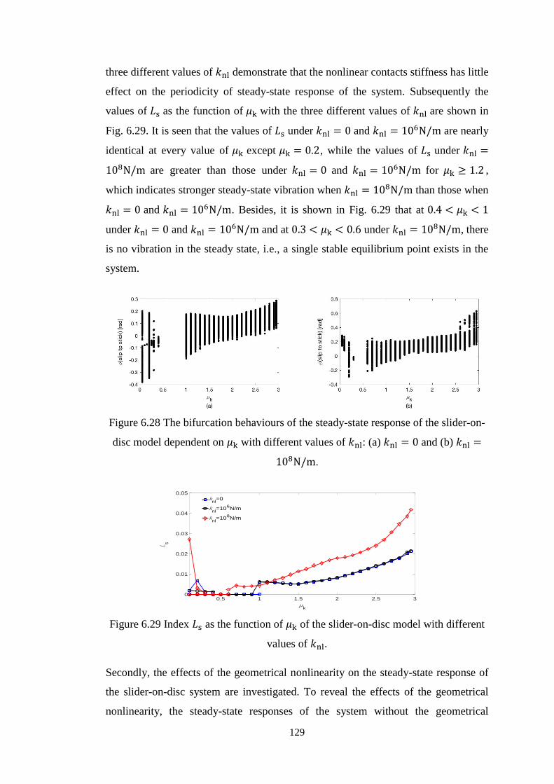
Figure 628 The bifurcation behaviours of the steady-state response of the slider-on-
disc model dependent on 120583k with different values of 119896nl (a) 119896nl = 0 and
(b) 119896nl = 108Nm 129
Figure 629 Index 119871s as the function of 120583k of the slider-on-disc model with different
values of 119896nl 129
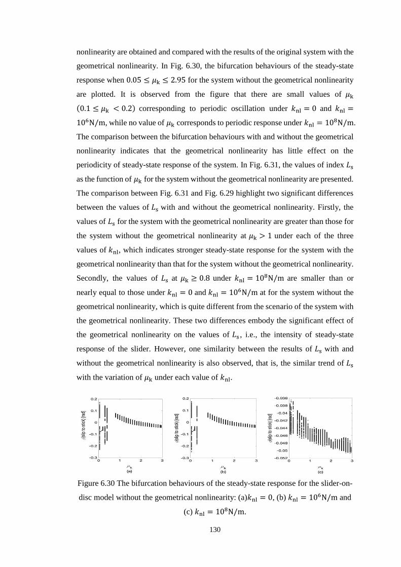
Figure 630 The bifurcation behaviours of the steady-state response for the slider-on-
disc model without the geometrical nonlinearity (a)119896nl = 0 (b) 119896nl =
106Nm and (c) 119896nl = 108Nm 130
Figure 631 Index 119871s as the function of 120583k for the slider-on-disc model without the
geometrical nonlinearity 131
XXI
Figure 632 The bifurcation behaviours of the steady-state response for the slider-on-
disc model with the second kind of assumption about the states of
motion (a)119896nl = 0 (b) 119896nl = 106Nm and (c) 119896nl = 10
8Nm 132
Figure 633 Index 119871s as the function of 120583k for the slider-on-disc model with the
second kind of assumption about the states of motion 132
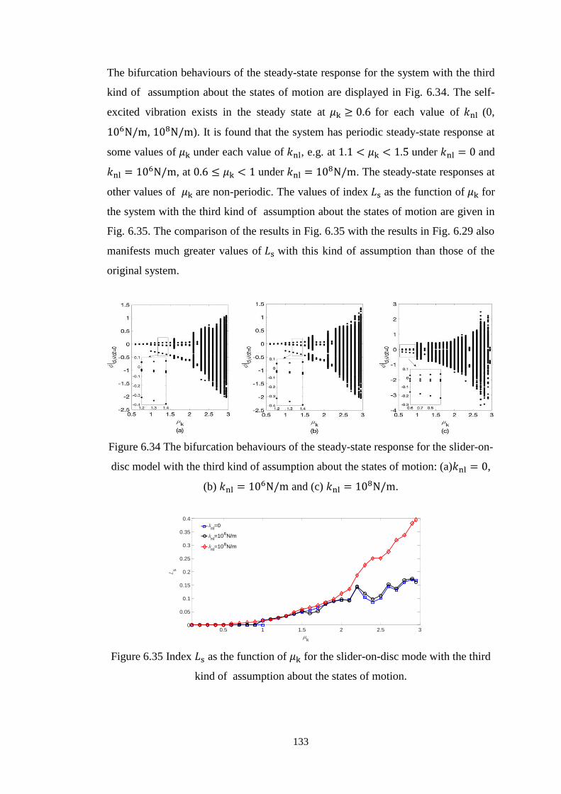
Figure 634 The bifurcation behaviours of the steady-state response for the slider-on-
disc mode with the third kind of assumption about the states of motion
(a)119896nl = 0 (b) 119896nl = 106Nm and (c) 119896nl = 10
8Nm 133
Figure 635 Index 119871s as the function of 120583k for the slider-on-disc model with the third
kind of assumption about the states of motion 133
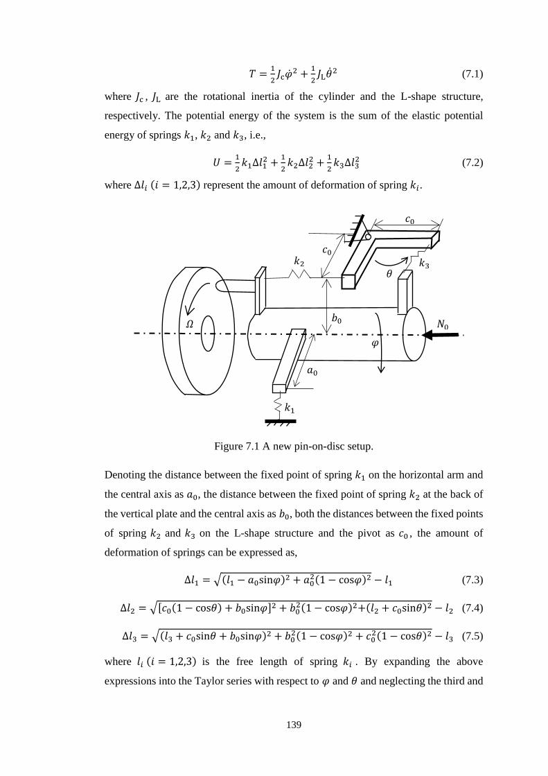
Figure 71 A new pin-on-disc setup 139
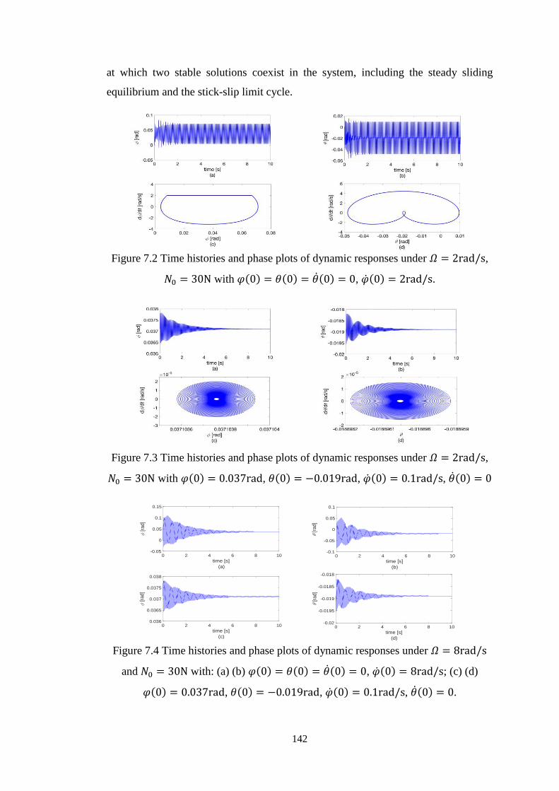
Figure 72 Time histories and phase plots of dynamic responses under 120570 = 2rads
1198730 = 30N with 120593(0) = 120579(0) = (0) = 0 (0) = 2rads 142
Figure 73 Time histories and phase plots of dynamic responses under 120570 = 2rads
1198730 = 30N with 120593(0) = 0037rad 120579(0) = minus0019rad (0) =
01rads (0) = 0 142
Figure 74 Time histories and phase plots of dynamic responses under 120570 = 8rads
and 1198730 = 30N with (a) (b) 120593(0) = 120579(0) = (0) = 0 (0) = 8rads
(c)(d) 120593(0) = 0037rad 120579(0) = minus0019rad (0) = 01rads
(0) = 0 142
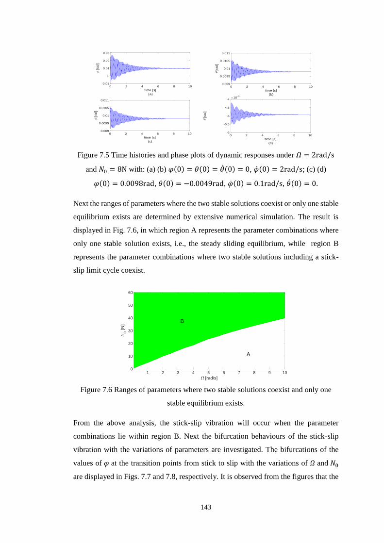
Figure 75 Time histories and phase plots of dynamic responses under 120570 = 2rads
and 1198730 = 8N with (a) (b) 120593(0) = 120579(0) = (0) = 0 (0) = 2rads
(c) (d) 120593(0) = 00098rad 120579(0) = minus00049rad (0) = 01rads
(0) = 0 143
Figure 76 Ranges of parameters where two stable solutions coexist and only one
stable equilibrium exists 143
Figure 77 The bifurcation behaviour of the stick-slip response of the system
dependent on the disc speed when 1198730 = 30N 144
XXII
Figure 78 The bifurcation behaviour of the stick-slip response of the system
dependent on the preload when 120570 = 2rads 144
Figure 79 The bifurcation behaviour of the stick-slip response of the undamped
system dependent on (a) the disc speed and (b) the preload 144
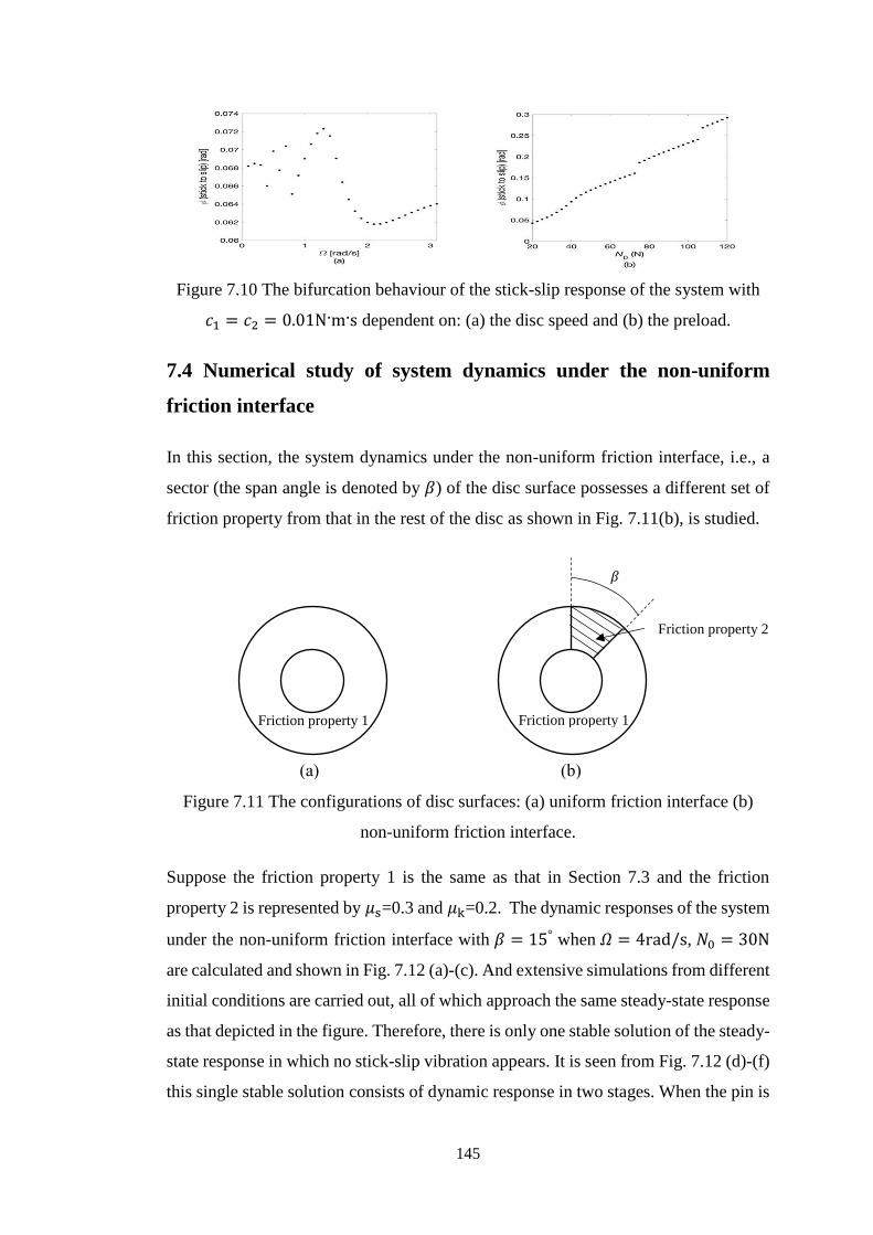
Figure 710 The bifurcation behaviour of the stick-slip response of the system with
1198881 = 1198882 = 001Nms dependent on (a) the disc speed and (b) the
preload 145
Figure 711 The configurations of disc surfaces (a) uniform friction interface (b) non-
uniform friction interface 145
Figure 712 The dynamic responses under the non-uniform friction interface with
120573 = 15deg and comparisons with the responses under the uniform friction
interface when 120570 = 4rads 1198730 = 30N (a-c) and the zoom-in plot of
dynamic responses under the non-uniform friction interface during 119905 =
[6 93]s (d-f) 147
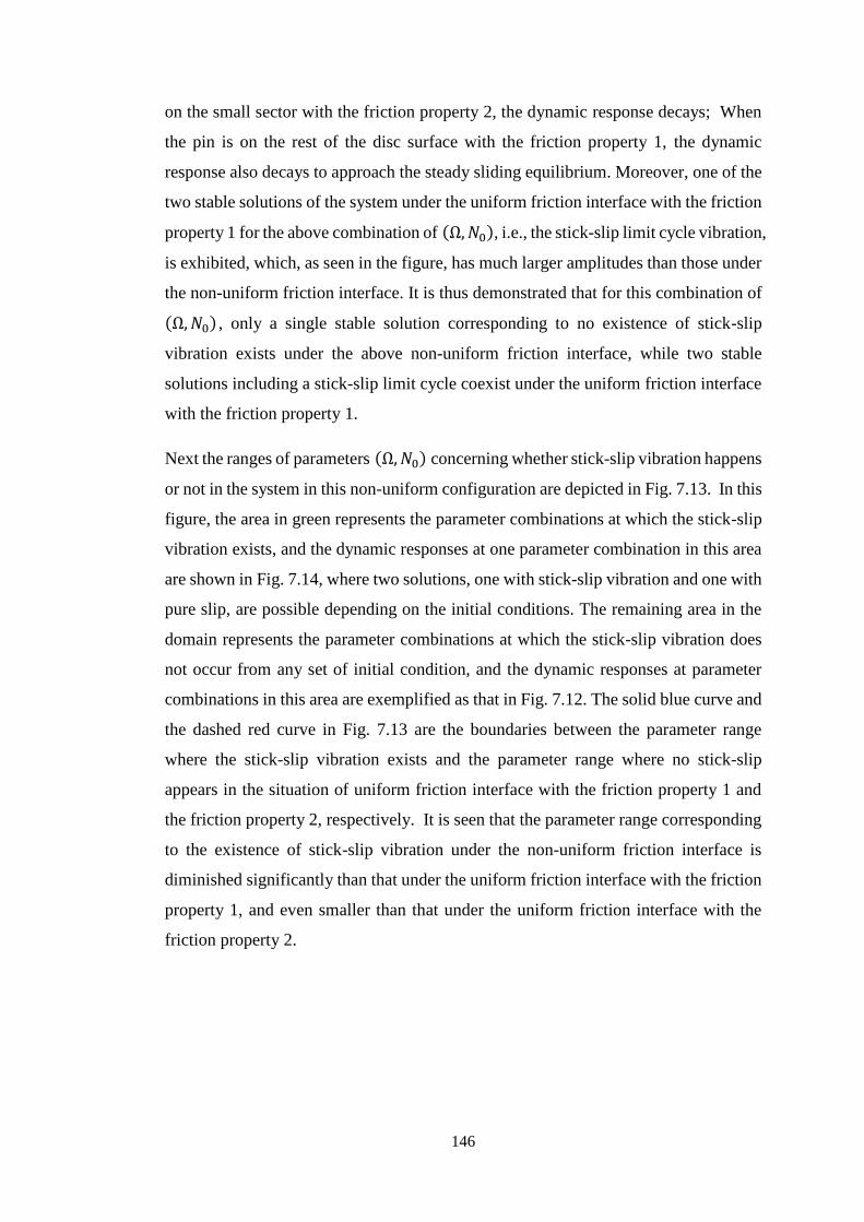
Figure 713 Ranges of parameters (Ω1198730) as to whether the stick-slip vibration
happens or not in the system 147
Figure 714 The two solutions of dynamic response under the non-uniform friction
interface when Ω = 1rads 1198730 = 30N (a) with stick-slip vibration and
(b) with pure slip 147
Figure 715 Ranges of parameters (Ω1198730) as to whether the stick-slip vibration
happens or not under the non-uniform friction interface with different
120573 148
Figure 716 Ranges of parameters (Ω1198730) as to whether the stick-slip vibration
happens or not under the non-uniform friction interface with different 120573
when 1198881 = 1198882 = 001Nms 149
Figure 717 Effective coefficients of static and kinetic friction of the friction property
2 on the sector 149
XXIII
List of Tables
Table 41 The values of constant parameters of the slider-on-disc system for the
investigation of effects of time-varying spinning speed 62
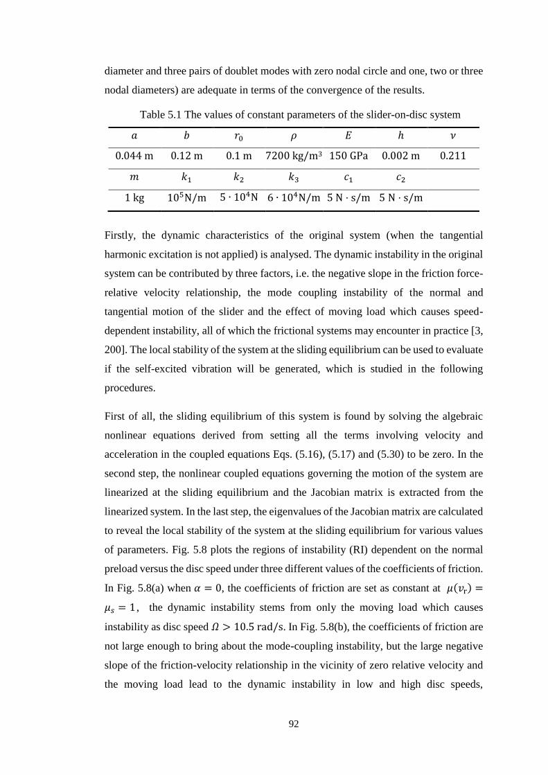
Table 51 The values of constant parameters of the slider-on-disc system for the
analysis of effects of tangential harmonic excitation 92
Table 61 The values of constant system parameters of the 5-DoF frictional model for
the analysis of effects of multiple types of nonlinearities 106
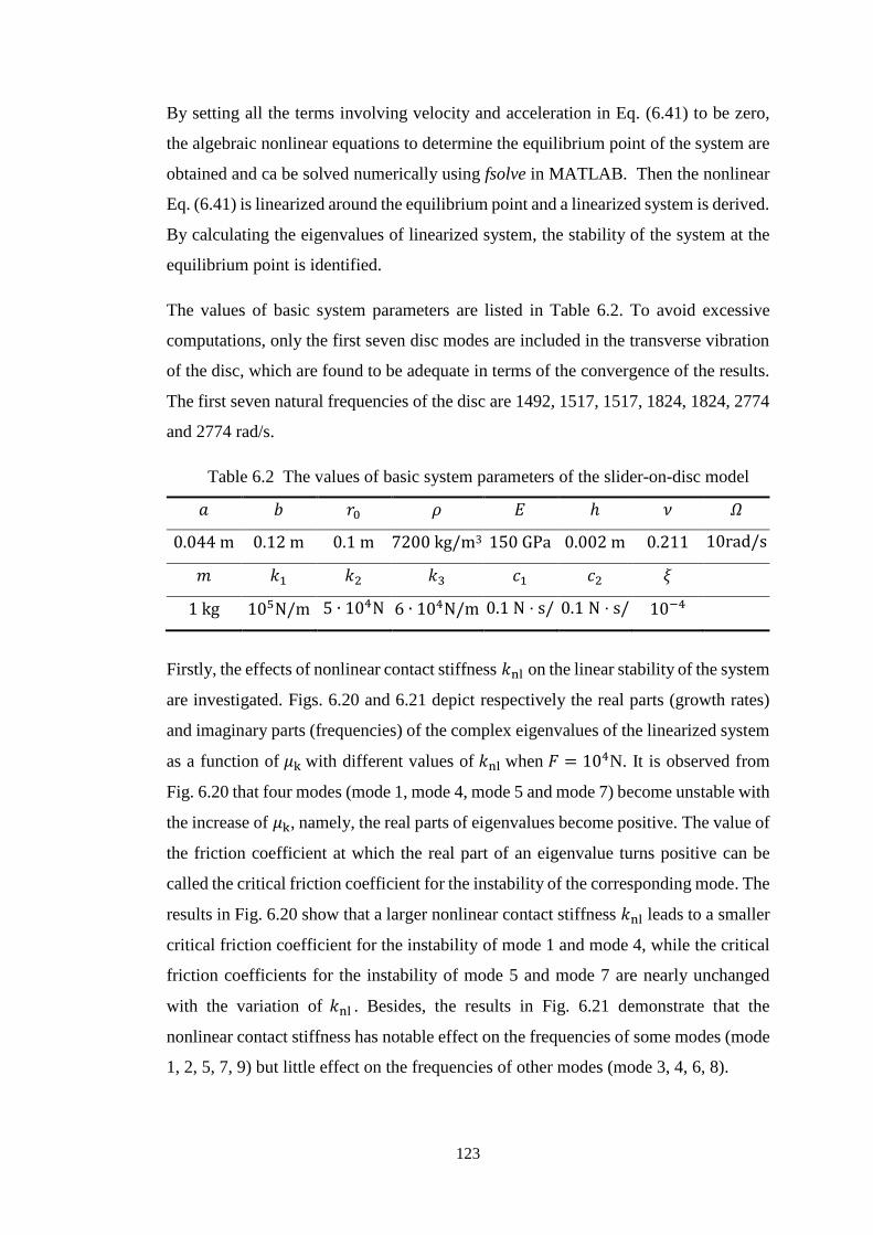
Table 62 The values of basic system parameters of the slider-on-disc model for the
analysis of effects of multiple types of nonlinearities 123
Table 71 The values of basic system parameters of a new pin-on-disc setup 141
XXIV
Nomenclature
119860b 119860 the amplitudes of the tangential harmonic excitation on the
slider in the two-degree-of-freedom friction model and on
the slider in the slider-on-disc model in Chapter 5
1198860 1198870 1198880 the distance between the fixed point of the spring 1198961 on the
horizontal arm and the central axis the distance between the
fixed point of the spring 1198962 at the back of the vertical plate
and the central axis and both the distances between the fixed
points of the spring 1198962 and 1198963 on the L-shape structure and
the pivot respectively in the setup in Chapter 7
119886 119887 120588 119864 ℎ 120584 the inner radius the outer radius the density of material the
Youngrsquos modulus the thickness the Poissonrsquos ratio of the
disc
1198881 1198882 the damping coefficients in the two-degree-of-freedom
mass-on-belt model and the two-degree-of-freedom friction
model in Chapter 3 or the damping coefficients on the slider
in the two-degree-of-freedom model and the slider-on-disc
model in Chapter 5 or the damping coefficients on the slider
in the 5-DoF frictional model and the slider-on-disc model in
Chapter 6 or the damping coefficients of rotation of the
cylinder and the L-shape structure in Chapter 7
119888 119896 the damping coefficient and stiffness of the single-degree-of-
freedom oscillator in Chapter 3
119888119911 119896119911 transverse damping coefficient and transverse spring
stiffness of the mass slider in the model in Chapter 4
1198884 1198885 1198886 the horizontal and vertical damping coefficients on the belt
in the 5-DoF frictional model in Chapter 6
119865 the normal preload on the two-degree-of-freedom friction
model in Chapter 3 or the two-degree-of-freedom model and
slider-on-disc model in Chapter 5 or the 5-DoF frictional
model and the slider-on-disc model in Chapter 6
119813T vector of friction force
119813N vector of normal force
119865f 119865T the tangential friction force between contacting objects
XXV
119865f1 119865f2 the friction forces on two masses in the two-degree-of-
freedom mass-on-belt model in Chapter 3
119813con(119857) the contact forces at the friction interface of the frictional
system
119813ext the external force applied on the friction system
119868 119888120593 119896120593 the moment of inertia in-plane damping coefficient and in-
plane spring stiffness of the mass slider in the model in
Chapter 4
119869 the rotational inertia about the mass centre of the belt in the
5-DoF frictional model in Chapter 6
119869c 119869L the rotational inertia of the cylinder and the L-shape
structure respectively in the setup in Chapter 7
1198961 1198962 the stiffnesses in the two-degree-of-freedom mass-on-belt
model or the stiffnesses of inclined springs in the two-
degree-of-freedom friction model in Chapter 3 or the
stiffnesses of inclined springs in the two-degree-of-freedom
friction model and the stiffnesses of the horizontal and
vertical springs in the slider-on-disc model in Chapter 5 or
the stiffnesses of the horizontal and vertical springs on the
slider in the 5-DoF frictional model and the slider-on-disc
model in Chapter 6 or the stiffnesses of two linear springs in
the setup in Chapter 7
1198963 the stiffness of vertical spring in the two-degree-of-freedom
friction model in Chapter 3 or the stiffness of vertical spring
in the two-degree-of-freedom friction model and the stiffness
of the inclined spring in the slider-on-disc model in Chapter
5 or the stiffness of the inclined spring in the 5-DoF
frictional model and the slider-on-disc model in Chapter 6
or the stiffness of one linear spring in the setup in Chapter 7
1198964 1198965 1198966 the stiffnesses of horizontal and vertical springs on the belt
in the 5-DoF frictional model in Chapter 6
119896nl the nonlinear contact stiffness in the 5-DoF frictional model
or the slider-on-disc model in Chapter 6
1198971 1198972 the distances between the wheels and mass centre of the belt
in the 5-DoF frictional model in Chapter 6 or the original
lengths of two linear springs in the setup in Chapter 7
1198973 the original length of one linear spring in the setup in Chapter
7
XXVI
119898 the mass of the single-degree-of-freedom oscillator in
Chapter 3 or the mass of the slider in the two-degree-of-
freedom model in Chapter 3 and Chapter 5 or the mass of
slider in the slider-on-disc models in Chapter 4 Chapter 5
and Chapter 6 or the mass of the belt in the 5-DoF frictional
model in Chapter 6
119872 the mass of the slider in the 5-DoF frictional model in
Chapter 6
1198981 1198982 the masses in the two-degree-of-freedom mass-on-belt
model in Chapter 3
119820 119810 119818 the mass matrix damping matrix and stiffness matrix of a
frictional system
1198730 the normal preload on the model in Chapter 4 or the setup in
Chapter 7
119873 119865N the normal force between contacting objects
1199030 the radial distance of the mass slider from the disc centre in
Chapter 4
119905s the time at the onset of stick
1199060 the amplitude of the external excitation on the single-degree-
of-freedom friction oscillator
119907 the velocity of belt in the mass-on-belt models in this thesis
119907r the relative velocity between contacting objects
119855rel vector of relative velocity between contacting surfaces
119907s the Stribeck velocity
119907tol the tolerance velocity of the linear smooth function for the
Coulombrsquos friction model
119908(119903 120579 119905) the transverse displacement of an annular elastic thin plate
1205720 the negative slope of the friction force-relative velocity
relationship 1205721 1205722 the angles of inclination to the horizontal direction of
inclined springs in the two-degree-of-freedom friction model
in Chapter 3 or the two-degree-of-freedom friction model in
Chapter 5
120583 1205830 1205831 120572 the friction coefficient the maximum value the asymptotic
value and the initial slope of the friction coefficient in
Chapter 4
120583s 120583k the coefficients of static friction and kinetic friction
XXVII
120590 the smoothness factor for the hyperbolic tangent function to
approximate the Coulombrsquos friction model
120596 the frequency of the external excitation on the single-degree-
of-freedom friction oscillator in Chapter 3 or the frequency
of the tangential harmonic excitation on the slider in the two-
degree-of-freedom friction model and on the slider in the
slider-on-disc model in Chapter 5
120570 the spinning speed of disc
1205700 119905max the initial speed and the time duration of the deceleration
process in the situation of decelerating disc in Chapter 4
1205701 119886d the initial speed and the acceleration in the situation of
accelerating disc in Chapter 4
120570c the constant disc speed in Chapter 4
1
Chapter 1
Introduction
11 Background and motivations
Dry friction which results from the relative motion of solids plays a crucial
controlling role in a rich variety of mechanical systems as well as in everyday life In
many cases friction acts as damping which develops between contact surfaces such as
joints or connections to dissipate energy and weaken vibration However friction force
can also cause self-excited vibration and lead to radiation of sound in various
engineering applications and daily life Examples of the vibration and sound which are
generated by dry friction include string instrument music rattling joints of robots
squealing windscreen wipers stick-slip vibration of drill-strings squeal noise of train
wheels on sharp curved tracks squeaking chalks on boards some insect sounds
automobile brake noises etc [12] Among them automobile brake noise has been a
major issue facing car manufacturers today which may cause discomfort to passengers
and be perceived as a quality problem thereby increasing the warranty costs and
impacting the brand reputations [34]
Due to the universality and importance of this problem friction induced vibration has
attracted great research interest and a considerable volume of literature has been
produced of this subject on both theoretical studies and experimental studies In terms
of theoretical studies theoretical mechanical models involving friction induced
vibration that include low-degree-of-freedom lumped models continuous models and
finite element models were established for investigation In terms of experimental
studies test rigs were specially designed to study the friction induced vibration in
2
specific mechanical systems These studies enormously enhanced the understanding
of this subject Physical mechanisms for initiating friction induced vibration were
uncovered such as the stick-slip vibration the sprag-slip instability the mode-
coupling instability the frictional follower force etc Methods to predict the
propensity of friction induced self-excited vibration and approaches to suppress the
friction induced vibration were proposed And the complex dynamic behaviours of the
friction induced vibration such as bifurcations and chaotic behaviours of the dynamic
responses were revealed
However the problem of friction induced vibration is not fully resolved yet and more
research especially from the theoretical perspective needs to be done The
deficiencies in existing studies constitute the motivation for the research in this thesis
For example a comprehensive study of the effects of multiple types of nonlinearities
on friction induced vibration is yet to be done Compared to the experimental study
the theoretical study is more advantageous in uncovering the basic mechanisms
predicting the dynamic behaviours unavailable in experiments and investigating the
effects of parameters on the friction induced dynamics
12 Aim and objectives
The aim of the present thesis is to study the friction induced vibration in theoretical
mechanical models in order to provide deeper understanding about the causes the
dynamic behaviours and the suppression of the friction induced vibration in
mechanical systems
To achieve this aim four objectives are established which are
(1) To build a theoretical mechanical model which consist of a mass-slider constrained
by in-plane and transverse springs and dampers with an elastic disc clamped at the
inner boundary and free in outer boundary in frictional contact and to study the
dynamics of the system in three different situations of spinning speed of disc ie
constant deceleration constant acceleration and constant speed The system
responses under the decelerating and accelerating sliding motion are compared
with the results under constant sliding speed to help reveal the effects of
deceleration and acceleration on the friction induced dynamics of the system
3
(2) To investigate the effects of tangential harmonic excitation on the friction induced
vibration in two multi-degree-of-freedom (MDoF) systems that are coupled in the
tangential and normal directions ie a two-degree-of-freedom lumped model and
a more complicated slider-on-disc model The analytical method to determine the
effective ranges of the amplitude and frequency of the harmonic excitation for the
suppression of the friction induced vibration of the systems is established and the
analytical results are verified by the results obtained from a large number of
simulations of the time responses of systems in various combinations of values of
the amplitude and frequency
(3) To study the friction induced vibration of a five-degree-of-freedom mass-on-
oscillating-belt model considering multiple types of nonlinearities The significant
effects of each type of nonlinearity on the linear stability and nonlinear steady-state
responses of the system are investigated This study is also extended to a
continuous slider-on-disc model
(4) To propose a new pin-on-disc system with an L-mechanism to create a state-
dependent normal force and couple with the friction induced stick-slip tangential
vibration of the system Especially the friction induced dynamics with a non-
uniform friction interface on the disc is investigated
13 Original contributions
The original contributions in this thesis can be summarised in five aspects as follows
(1) A numerical algorithm for the transient dynamic analysis of friction induced
vibration involving three different states of motion (slip and stick in contact and
separation and considering the impact when re-contact happens) is proposed
(2) The friction induced dynamics of a slider-on-disc system at time-varying spinning
disc speeds is investigated The distinct dynamic behaviours of the system under
time-varying disc speeds from those under constant disc speeds indicate the
necessity to consider the time-variant sliding velocity when studying the friction
induced vibration in mechanical systems
(3) The ranges of amplitude and frequency of the intentionally introduced tangential
high-frequency harmonic excitation to suppress the friction induced vibration in
4
two theoretical mechanical models are determined both analytically and
numerically This research can provide theoretical guidance for the suppression of
friction induced vibration in real mechanical systems by application of a tangential
harmonic excitation
(4) A comprehensive analysis of the effects of multiple types of nonlinearities on the
friction induced vibration is conducted It is discovered that each type of
nonlinearity has significant effects on the linear stability and nonlinear steady-state
responses of the mechanical models proposed therefore it is essential to take
multiple types of nonlinearities into account in the research of friction induced
vibration
(5) A new pin-on-disc model with an L-mechanism to adjust the normal force is
proposed and the friction induced dynamics of the system with non-uniform
friction interface where a sector of disc surface is assigned with a different set of
friction property from that on the rest of the disc surface is studied It is found that
with appropriate friction coefficients on the sector and an appropriate span angle
of the sector the range of disc speeds and normal preloads at which the stick-slip
limit cycle exists will be greatly diminished Therefore a promising approach to
suppress the friction induced stick-slip vibration is provided
14 Outline of the thesis
This thesis consists of eight chapters and the content of each chapter is briefly stated
as follows
Chapter 1 introduces the background and motivations the aim and objectives the
original contributions and the outline of this thesis
Chapter 2 provides a comprehensive literature review concerning friction induced
vibration in five aspects the main physical mechanisms for initiating friction induced
vibration the friction force models the dynamic behaviours of friction induced
vibration in a variety of mechanical models the dynamics of the spinning disc in
contact with stationary parts and the experimental investigations on the friction
induced vibration in mechanical systems
5
Chapter 3 presents the fundamental knowledge and analysis tools that are utilized in
the present thesis Firstly three principal mechanisms for generating friction induced
vibration that are the negative friction-velocity slope the stick-slip oscillation and the
mode-coupling instability are presented in low-degree-of freedom lumped models
Secondly two main kinds of theoretical methods of friction induced vibration ie the
complex eigenvalue analysis (CEA) and the transient dynamic analysis (TDA) are
introduced Finally the basic theory about the vibration of elastic thin plates is stated
Chapter 4 studies friction induced vibration of a mass-slider with in-plane and
transverse springs and dampers in sliding contact with a spinning elastic disc in three
different situations of spinning speeds ie constant deceleration constant acceleration
and constant speed The non-smooth dynamic responses of the system including three
different states of motion ie slip stick and separation are calculated And the
dynamic responses in the three different situations of disc speed are compared to reveal
the effects of time-variant disc speed on the friction induced dynamics of the system
Chapter 5 investigates the effects of tangential high-frequency harmonic excitation
on the friction induced vibration in multi-degree-of-freedom (MDoF) systems that are
coupled in the tangential and normal directions It is observed the friction induced
vibration of the systems can be suppressed by the tangential harmonic excitation when
the amplitude and frequency of the excitation are in certain ranges The ranges of
amplitude and frequency of the tangential harmonic excitation to suppress the friction
induced vibration in the systems are then determined both analytically and numerically
Chapter 6 studies the friction induced vibration of a five-degree-of-freedom mass-on-
oscillating-belt model considering multiple types of nonlinearities The first type of
nonlinearity is the nonlinear contact stiffness the second is the non-smooth behaviour
including stick slip and separation and the third is the geometrical nonlinearity caused
by the moving-load feature of the mass on the rigid belt Both the linear stability of the
system and the nonlinear steady-state responses are studied The effects of each type
of nonlinearity on the system dynamics are revealed The similar study is also
conducted on a continuous slider-on-disc model
Chapter 7 studies the friction induced stick-slip vibration of a new pin-on-disc system
with an L-mechanism to adjust the normal force And the friction induced dynamics
with a non-uniform friction interface on the disc is investigated
6
Chapter 8 presents important findings and conclusions in this PhD project and points
out some future directions of research
7
Chapter 2
Literature review
There have been a large number of published studies on the friction induced vibration
which greatly enhances understanding of the problem In this chapter the literature of
this subject is reviewed in five aspects Firstly several main physical mechanisms for
initiating friction induced vibration are reviewed then a review of various friction
force models is conducted thirdly the works on investigation of the dynamic
behaviours of friction induced vibration in a diverse variety of mechanical models are
presented The fourth part focuses on the literature concerning the dynamics of the
spinning disc in contact with stationary parts Finally in the fifth part the experimental
investigations on the friction induced vibration in mechanical systems are reviewed
21 Mechanisms for generation of friction induced vibration
From previous studies the mechanisms for the occurrence of friction induced vibration
generally fall into four categories [5] (1) stickndashslip oscillation which usually happens
when the value of static friction coefficient is greater than the kinetic friction
coefficient (2) sprag-slip instability for which the origin of instability is geometrical
rather than tribological (3) negative gradient in friction coefficientndashvelocity
relationship and (4) mode-coupling instability or mode-locking which is generally
acknowledged as the main mechanism for self-excited vibration in automobile brakes
211 Stick-slip oscillation
Stick-slip oscillation features two distinct states of motion sticking (when the two
objects in contact are at rest relatively and the static friction force between them does
8
not exceed the maximum static friction capacity) and slipping (when the two objects
are in relative motion) The stick-slip vibration serves to be the cause of vibration
instability in a number of mechanical systems [6-14] or in geodynamics [15-17] In
[18] Feeny et al gave a substantial historical review on the friction influenced
dynamics and stick-slip phenomena in mechanical civil and transportation systems
Since the dynamic states of a system experience non-smooth transitions such a system
belongs to the class of non-smooth systems which can exhibit chaotic behaviour [19]
Popp et al [2 19 20] investigated stick-slip dynamics of discrete and continuous
models and observed the rich bifurcation and chaotic behaviour could appear for the
models with the governing equations which could be expressed as three- or higher-
dimension first-order ordinary differential equations The observations of the
bifurcation and chaotic behaviour associated with stick-slip were also made by other
researchers [21-23] The works investigated the characteristics of stick-slip motion
which are influenced by the system parameter values and friction property [24-27]
Kinkaid et al [28] studied the dynamics of a 4-DoF (degree-of-freedom) system with
a two-dimension friction force and found the change of direction of the friction force
could excite unstable vibration even with the Coulombrsquos friction law thereby
introducing a new mechanism for brake squeal Behrendt et al [29] conducted a finite
element analysis on the stick-slip motion of an elastic brake pad sliding over a rigid
surface under constant load and constant velocity
In [30] a systematic procedure to find both stable and unstable periodic stick-slip
vibrations of autonomous dynamic systems with dry friction was derived in which the
discontinuous friction forces were approximated by a smooth function Hetzler [31]
studied the effect of damping due to non-smooth Coulomb friction on a simple
oscillator on the belt exhibiting self-excitation due to negative damping in the case of
negative friction force-relative velocity slope Tonazzi et al [32] performed an
experimental and numerical analysis of frictional contact scenarios from macro stick-
slip to continuous sliding Papangelo [33] investigated the subcritical bifurcation of a
slider-on-belt system which experienced friction induced vibration in the case of a
weakening-strengthening friction law and the results showed that there was a range of
parameters where two stable solutions coexist ie a stable sliding equilibrium and a
stable stick-slip limit cycle The approximate analytical expressions for the amplitude
and frequency of friction induced stick-slip oscillations were derived in [34] The
9
stick-slip vibration in the situation of decelerating sliding was investigated in [35 36]
the results showed that decelerating sliding can induce stick-slip whereas no stick-slip
appears during steady sliding
The literature showed that the stick-slip oscillation is widespread in engineering and
other fields and it can produce complex dynamic behaviours
212 Sprag-slip instability
The sprag-slip is not tribological but geometrical instability The concept of sprag-slip
was firstly proposed by Spurr [37] in which the variations of normal and tangential
forces due to the deformations of contacting structures were considered to cause the
vibration instability Jarvis and Mills [38] employed a cantilevered beam on disc to
examine sprag-slip instability in braking systems Earles et al [39] showed the
necessary condition for instability in terms of the contact orientation in a simple pin-
on-disc model Sinou et al [40] studied the instability in a nonlinear sprag-slip model
with a constant coefficient of friction by a central manifold theory and the effects of
parameters on the sprag-slip instability were examined
Another notable line of research focused on the existence and uniqueness of the
solutions of the frictional systems Painleveacute [41] investigated the existence and
uniqueness properties of the solutions of rigid bodies subjected to the Coulomb-type
sliding friction by using a rigid beam model It was noticed that there was a possibility
of multiple solutions and non-existence of (static) solutions due to the nonlinearity
arising from the friction model The phenomenon is called the Painleveacute paradox Leine
et al [42] studied the periodic motion and bifurcations of a frictional impact oscillator
which consisted of an object with normal and tangential degrees of freedom in contact
with a rigid surface It was shown that this type of systems could exhibit the Painleveacute
paradox ie non-uniqueness and non-existence of solutions for physically realistic
values of the friction coefficient Hoffmann et al [43 44] examined the dynamics of
sprag-slip instability and found that there were parameter combinations for which the
system did not possess a static solution corresponding to a steady sliding state which
could be a sufficient condition for occurrence of sprag-slip oscillation Kang and
Krousgrill [45] developed simple friction-coupled models with spragging forces by
using a mass on a traveling belt in both one- and two-dimension spaces and determined
10
the condition for non-existence of steady-sliding response through analytical and
numerical procedures
Although the interest on the sprag-slip mechanism has lessened since the mode-
coupling mechanism gained acceptance as a dominant factor in the initiation of brake
squeal it is still studied today as a mechanism for the dynamic instability in many
applications
213 Negative gradient in friction coefficientndashrelative velocity relationship
The idea that the negative slope in friction coefficientndashrelative velocity relationship
accounted for the instability of a brake system was previously proposed by Mills [46]
Fosberry and Holubecki [47] Sinclair and Manville [48] The decreasing feature of
friction force with the increase of relative velocity was considered to bring in a
negative damping to the system and lead to dynamic instability The negative damping
effect due to the negative friction-velocity slope was investigated by many researchers
[49-51] Ouyang et al [52] demonstrated the effect of the negative friction-velocity
slope on the parametric resonances of a flexible annular disc excited by a rotating
mass-spring-damper system together with a frictional follower force In [33] the
negative slope of friction force at the static equilibrium determined the linear stability
boundary for the system
There was not much literature on this kind of mechanism as it can only explain a
limited number of fiction-induced-vibration problems [3 53]
214 Mode-coupling instability
The mode-coupling instability originates from the modal behaviour of the structures
in contact The complex eigenvalue analysis shows that some modes become unstable
when coupling with other modes of the friction system This phenomenon was
considered to be mainly responsible for brake squeal and has been widely studied [54-
62]
North firstly observed the mode-coupling phenomenon when studying brake squeal
that could also happen for a constant friction coefficient [54] Hoffmann et al [55]
used a minimal two degree-of-freedom model to clarify the physical mechanisms
underlying the mode-coupling instability of friction induced oscillations from an
11
intuitive perspective It was shown that the friction force acts like a cross-coupling
force linking motion normal to the contact surface to motion parallel to it and that a
necessary condition for the onset of instability is that the friction induced cross-
coupling force balances the corresponding structural cross-coupling force of the
system In a later work [56] Hoffmann and Gaul clarified the influence of structural
damping on this type of instability mechanism It was shown that linear viscous
structural damping changes the eigenvalue characteristics of mode-coupling friction
induced instability Kang et al [57] presented the mathematical formulation for
determining the dynamic in terms of the self-excited transverse vibration of a thin
annular plate in which the mode-coupling instability of the disc doublet modes was
investigated
Huang et al [63] showed that the compatibility of mode shapes needed for mode
coupling is one of the factors dictating the onset of squeal in drum brake system
Elmaian et al [4] presented a wide diversity of responses on a same dynamic system
by changing the parameter values and showed the squeal was mainly due to the mode-
coupling phenomenon Hulteacuten [64] proposed a new kind of mode-coupling mechanism
that the coupling of the system was not due to the inclined spring but the friction forces
in two orthogonal directions Chen et al [61] investigated the eigenvalues of several
car brakes through experimental and numerical analysis and predicted that the
coupling of the in-plane and out-of-plane modes of the brake was the main reason for
squeals above 3 kHz
215 Additional Mechanisms
Apart from the four principal mechanisms above there are other mechanisms proposed
to explain the occurrence of friction induced vibration in specific systems Chan et al
[65] analysed the destabilizing effect of the friction force as a follower force
Hochlenert et al [66] established an accurate formulation of the kinematics of the
frictional contact in two and three dimensions and worked out the essential properties
of the contact kinematics leading to self-excited vibration Ouyang and Mottershead
[67] investigated the instability of the transverse vibration of a disc excited by two co-
rotating sliders on either side of the disc and found that the moving normal forces and
friction couple produced by the sliders bring about dynamic instability Chen et al [68]
analysed the instability of a friction system caused by the time delay between the
12
normal force and the friction force Graf and Ostermeyer [69] utilized a dynamic
friction law with an internal variable in the classical mass-on-belt model and found the
stability of the system was dependent on the relation between the eigenfrequency of
the oscillator and the time constants in the dynamic friction law where the unstable
vibration could even happen in the case of a positive friction-velocity relationship
22 Friction force models for dynamic analysis
Friction forces of complicated nature can be found in all practical mechanical systems
which have contacting surfaces with relative motion To obtain accurate dynamic
responses of the systems with friction force rigorous evaluation of friction forces is
required There has been a great amount of literature devoted to developing friction
force models that can be used to capture the frictional behaviour such as stick-slip
effect Stribeck effect and pre-sliding displacement etc Generally the friction force
models can be classified into two groups namely the lsquostaticrsquo and lsquodynamicrsquo friction
models The former group usually describes the steady-state behaviour of friction force
while the latter can capture more friction characteristics due to the inclusion of extra
state variables
221 lsquoStaticrsquo friction models
One of the first models of friction was put forward by Amontons [70] and Coulomb
[71] who stated that the friction force is proportional to the normal force and
independent of the magnitude of relative velocity Besides the static coefficient of
friction is assumed to be equivalent to the kinetic coefficient of friction therefore the
Coulomb friction law involves a single parameter that is the kinetic coefficient of
friction The mathematical expression of Coulomb friction law can be written as
119813T = 120583k119813Nsgn(119855rel) 119855rel ne 0119813T le 120583k119813N 119855rel = 0
(21)
where sgn(119855rel) = 119855rel119855rel 119813T 119813N and 119855rel represent the friction force the normal
force and the relative velocity between the contacting surfaces respectively The
friction force during sticking when 119855rel = 0 serves to sustain the relative static state
and thus can be obtained from the equations of motion of systems while the magnitude
of static friction force cannot exceed the maximum static friction capacity 120583k119813N
Further studies on frictional behaviour suggested the maximum static friction force
13
should be larger than the kinetic friction force which led to consideration of two
different friction coefficients namely the coefficient of static friction 120583s and the
coefficient of kinetic friction 120583k (120583s gt 120583k ) As a modification of the Coulombrsquos
friction law a viscous friction component was introduced to describe the linear
relationship between the friction force related to the lubricant viscosity and the relative
velocity The friction force during relative sliding can be written as
119813T = 120583k119813Nsgn(119855rel) + 119865v119855rel (22)
where 119865v is the viscous friction coefficient related to the viscosity of the lubricant
Stribeck [72] found experimentally that the friction force decreases with the increase
in the relative velocity at low velocities which led to the expression of friction force
during relative sliding as a continuous and decreasing function of the relative velocity
A popular expression of the friction force during the relative sliding which considered
the Stribeck effect was written as [73]
119813T = (120583k + (120583s minus 120583k)eminus(
119855rel
119907s)120575
) 119813Nsgn(119855rel) (23)
where 119907s denotes the Stribeck velocity 120575 is a factor relying on the geometry of the
contacting surfaces The examples of variations of the friction force with the relative
velocity in the above four different friction models for the one-dimensional (1D) case
are illustrated in Figure 21
F
vrel
microkFN
vrel
F F
vrel vrel
F
(a) (b) (c) (d)
-microkFN
microsFN
microkFN
-microsFN
-microkFN
microkFN
-microkFN
microsFN
microkFN
-microkFN
-microsFN
Figure 21 Friction force versus relative velocity for 1D case (a) Coulomb friction
model (b) Coulomb model with larger static friction force (c) Coulomb friction with
viscous friction (d) Model with Stribeck effect
In the aforementioned static friction models the friction force at zero relative velocity
is multivalued and needs to be determined from the equations of motion of systems
Thus it is essential to accurately capture the transition between the stick mode and the
14
slip mode which brings about numerical difficulty for the dynamic analysis of the
frictional systems To improve the computational efficiency several researches
proposed friction models which replaced the discontinuity at zero velocity by finite
slopes Two approaches were widely used which employ a linear function [74] or a
hyperbolic tangent function [30 75] to describe the friction force-relative velocity
relationship around zero velocity The mathematical expressions of the two smoothing
approaches for the Coulombrsquos friction model can be written as
119813T = 120583k119813Nsgn(119855rel) 119855rel gt 119907tol120583k119813N119855rel119907tol 119855rel le 119907tol
(24)
for linear function where 119907tol is the tolerance velocity and
119813T = 120583k119813Ntanh(120590119855rel)sgn(119855rel) (25)
for hyperbolic tangent function where 120590 is the smoothness factor The examples of
these two friction models for 1D case are shown in Figure 22
F
vrel
microkFN
-microkFN
F
vrel
microkFN
-microkFN
vtol
-vtol
Figure 22 Smooth functions to approximate the Coulomb friction model for 1D
case
In addition several acceleration-based friction models have been proposed in which
friction force is dependent on another variable besides the relative velocity ie the
relative acceleration between the contacting surfaces Stefański et al [76] put forward
a friction model which showed non-reversible friction characteristic The function of
this model is described as
119813T = 120583k119813N(1 +120583sminus120583k
120583kexp(minus119855rel)sign(119855rel ∙ rel)) sgn(119855rel) (26)
where sign(lowast) is the sign function Wojewoda et al [77] proposed a static friction
model of hysteretic type with a stochastic component This model is divided into three
15
different states sticking and sliding in acceleration and deceleration Its mathematical
expression is written as
119813T =
119865stsgn(119855rel) if 119865st le 119865d+ cap sign(119855rel ∙ rel) ge 0
119865d+sgn(119855rel) if 119865st gt 119865d+ cap sign(119855rel ∙ rel) ge 0
119865dminussgn(119855rel) if sign(119855rel ∙ rel) lt 0
(27)
with
119865st =1
2119896S
119855rel2
relminus 1198650 (28)
119865d+ = 119865C + (119865S + ∆119865S1
1+119855rel
119907S
minus 119865C) (119892(119855rel rel) + 119891R(119857 119855rel)) (29)
119865dminus = 119865C minus (119865S minus 119865C)(119892(119855rel rel) + 119891R(119857 119855rel)) (210)
where 119865C = 120583k119813N 119865S = 120583s119813N 119896S is the contact stiffness 1198650 is the initial value
for sticking force 119891R(119857 119855rel) is a stochastic function and 119892(119855rel rel) represents a
function to model the Stribeck curve An example of the friction characteristics of this
model is displayed in Figure 23
vrel
F
Fst
Fd+
Fd-
vS
Figure 23 Hysteretic behaviour of friction force
Besides Karnopp [78] developed a model where the velocity is considered zero for a
prescribed small range Leine et al [79] proposed the switch model as a modification
of Karnopp model Ambroacutesio [80] proposed a modified Coulombrsquos friction law
Awrejcewicz et al [81] presented a model which is dependent on both the tangential
force and the relative velocity
16
222 lsquoDynamicrsquo friction models
The lsquodynamicrsquo friction models are capable of capturing some friction phenomena such
as pre-sliding displacement or friction lag which are not reflected in the lsquostaticrsquo friction
models by introducing extra state variables
The Dahl friction model [82 83] introduced the pre-sliding displacement through a
new state variable 119859 and its formulation is expressed as a first-order differential
equation
d119859
d119905= (1 minus
1205900119859∙sgn(119855rel)
120583k119813N) 119855rel (211)
The friction force 119813T = 1205900119859 where 1205900 represents the stiffness coefficient of the bonds
between the two contacting surfaces In the steady state the Dahl friction model is
actually the Coulombrsquos friction model
Haessig and Friedland [84] proposed a model which considers that the friction force
results from the deformation of the asperities Each contact is modelled as a bond of a
rigid bristle and a flexible bristle which behaves as a linear spring The total friction
force is the resultant of all the spring forces due to relative motion ie
119813T = sum 120590119894(119857119894 minus 119835119894)119899119894=1 (212)
where n is the number of bristles bonded 120590119894 denotes the stiffness of the ith flexible
bristle 119857119894 is the position of the flexible bristle 119835119894 represents the position of the rigid
bristle This model is inefficient for numerical simulation therefore it is not usually
used
Canudas de Wit et al [85 86] developed the LuGre model in which the friction force
is also considered as the result of deformation of bristles while the average bristle
deflection is utilized An internal state variable 119859 is introduced to quantify the average
bristle deflection and the friction force is expressed as
d119859
d119905= (1 minus
1205900119859∙sgn(119855rel)
119892(119855rel)) 119855rel
119813T = 1205900119859 + 1205901d119859
d119905+ 1205902119855rel
(213)
where 1205900 1205901 are the stiffness and damping of the bristles respectively 119891(119855rel) is a
function that describes the viscous effect 119892(119855rel) is a function that considers the
17
Stribeck effect The LuGre model can be regarded as a derivation from the Dahl model
In [87] Piatkowski presented a method of determination of parameters for LuGre and
Dahl friction models
The reset integrator model [88] is also an evolution of the Dahl model In this model
the friction force originates from the elastic and plastic deformation of the surface
asperities Similarly an extra state variable 119859 is used to determine the deformation of
bristles in contact as
d119859
d119905=
120782 if 119859 ge 1199110 cap 119859 ∙ 119855rel gt 0119855rel otherwise
(214)
The friction force is defined as
119813T = 12059001199110sgn(119963) if 119859 ge 1199110
1205900(1 + 119886)119859 + 1205901d119859
d119905if 119859 lt 1199110
(215)
As shown above the reset integrator model consists of two state equations one for
slipping and another for sticking The transition between the two states occurs when
the deformation reaches its maximum value 1199110 which makes this model discontinuous
Besides Dupont et al [89] developed the elasto-plastic model which divided the
bodyrsquos displacement into the elastic displacement that represents the bristle deflection
and the plastic displacement that represents the macroscopic sliding displacement
Swevers et al [90] proposed the Leuven model which was an improvement over the
LuGre model Gonthier et al [91] introduced a two-dimensional friction model based
on the LuGre model Liang et al [92] extended the model proposed by Haessig and
Friedland [83] to the three-dimensional space
23 Investigation of friction induced vibration in mechanical models
Friction induced vibration in mechanical systems can exhibit rich dynamic behaviours
which have been revealed in a number of publications To study this problem various
mechanical models have been established which can usually be classified into three
categories namely the lumped models the continuous models and the finite element
models
18
231 Lumped models
Popp and Stelter [20] analysed the stick-slip oscillation of a 1-DoF slider-on-belt
system with external harmonic excitation and a 2-DoF slider-on-belt system The
results showed the bifurcation behaviours of the dynamic responses in the two systems
depending on the ratio between the excitation frequency and the natural frequency of
the oscillator and the ratio between two damping coefficients respectively Elmaian et
al [4] investigated the friction induced vibration of a three degree-of-freedom model
and found that three distinct dynamic states ie stick slip and separation can appear
in the vibration of this model and the time ratios of the three states in the whole process
vary with the system parameters which can be linked to the appearance of different
categories of noises ie no noise creak squeal and squeak Li and Feng [93]
examined the dynamics of a single-degree-of-freedom oscillator sliding over a rigid
surface with the LuGre friction model and found the chaotic motions can appear which
is not expected in a single-degree-of-freedom system because the LuGre friction model
contains one internal variable Pikunov and Stefanski [94] analysed the friction
induced dynamics of a 1-DoF mass-on-belt model with cubic nonlinearity and a
modified LuGre friction model By means of a method of estimation for non-smooth
systems Lyapunov exponent spectrum of the friction oscillator was calculated to be
used for observations of the nature of the oscillatorrsquos response
In Ref [95] a three-degree-of-freedom model of a pin-on-disc system was presented
and the effects of parameters including the normal force the rotational speed and the
pin stiffness on the system responses were revealed In Ref [96] the combined
problem of friction and impact of a single-degree-freedom oscillator colliding with an
obstacle and excited by a moving belt was studied Li et al [97] analysed the mode-
coupling phenomenon of a 2-DoF model with nonlinear contact stiffness and the
effects of separation and reattachment on the vibration amplitudes of dynamic
responses were studied Zhang et al [98] compared the results of system instability
obtained from three different methods ie the complex eigenvalue analysis (CEA)
the net work analysis and the nonlinear instability analysis in a 4-DoF friction
oscillator and found both the net work analysis and CEA under-predict the instability
due to their inability to detect the subcritical Hopf bifurcation Some work on friction
induced dynamics using low-degree-of freedom lumped models was also done in Refs
[2 19 28 33 55 56 62 99-102]
19
Kruse et al [103] explored the effect of joints on the stability and bifurcation behaviour
of a system subject to friction induced flutter It was shown that subcritical bifurcations
bifurcations from infinity and detached limit cycles can arise when the joint with
nonlinear dynamic behaviour is integrated in the system which indicate the severe
limitations of linear stability analysis based on the eigenvalue calculation of the
linearized model Pilipchuck et al [104] examined the non-stationary effects in friction
induced vibration of a two-degree-of-freedom brake model It was observed that the
system responses experienced qualitative transitions due to the linearly deceasing
velocity of the belt In particular there was a significant widening of frequency
spectrum of the dynamics in the final phase of the process Brunetti et al [105] studied
the dynamics of a periodic modular lumped model in which each module consists of a
mass in contact with the moving belt and a mass linked with the adjacent modules It
was shown that although the eigenvalues allow to indicate the stability of the system
they fail to indicate the frequency of the steady-state responses including the contact
nonlinearities ie stick-slip transition in the tangential direction and contact-no
contact in the normal direction A new energy index quantifying the capability of each
mode to exchange energy with the external environment was then introduced as a more
reliable indicator of the unstable frequency in the friction induced dynamic responses
In Ref [106] the stick-slip induced brake creep-groan phenomenon was investigated
by using a lumped torsional model and experiment
Li et al [107] investigated the dynamics of an archetypal self-excited smooth and
discontinuous oscillator driven by dry friction from the moving belt The complicated
dynamic behaviours of double tangency bifurcation the bifurcation of sliding
homoclinic orbit to a saddle subcritical Hopf bifurcation and grazing bifurcation for
this system can be demonstrated with the variations of parameters such as the friction
coefficients and the belt velocity In Ref [58] a novel two-degree-of-freedom model
involving a wobbling disc which can be easily associated with a disc brake was
proposed and its stability behaviour was analysed Wei et al [108] established a 3-
DoF dynamic model of a brake system consisting of two-layer pads and a rigid disc
and the bifurcation and chaotic behaviour of system responses dependent on the
variation of brake pressure and the parameters of double-layer pads were observed In
Ref [109] the vibration of a slider on the rough surface was examined by using a 2-
DoF theoretical model and experiment The Poissonrsquos impact law and Coulombrsquos
20
friction law were employed on the contact surfaces to incorporate the roughness effects
in the numerical simulation and the numerical solutions were found to agree with the
experiments In Ref [110] the impact of contact stiffness heterogeneities on friction
induced vibration was studied
Thomsen et al [34] considered the classical ldquomass-on-moving-beltrdquo model with a
discontinuous friction law and derived the approximate analytical expressions for the
conditions the amplitudes and the base frequencies of friction induced stick-slip and
pure-slip oscillations Hetzler et al [111] presented an analytical investigation on
stability and local bifurcation behaviour due to exponentially decreasing friction
characteristic in a ldquomass-on-beltrdquo oscillator The analytical work on the stability
analysis and limit cycles of the 1-DoF friction oscillator can also be seen from Refs
[112-114] In Ref [115] the Lyapunov exponents of the non-smooth 1-DoF mass-on-
belt model with external excitation were derived which was highly useful in
identifying the chaotic behaviour in the system Besides the smooth functions were
used to approximate the discontinuous friction law in some work Van de Vrande et al
[30] investigated the friction induced vibration of 1 and 2-DoF mass-on-belt models
and a 1-DoF drill string model by using smooth functions to approximate the
discontinuous friction forces and the results showed the smoothing procedure
accurately describes the behaviour of discontinuous systems Divenyi et al [116]
adopted a smoothing procedure to model the non-smooth dry friction between the
formation and drill bit to study the drill string vibration in a two-degree-of-freedom
model
Some literature focuses on the uncertainty analysis of friction induced vibration in
lumped models Nobari et al [117] studied the uncertainty quantification of the
complex eigenvalue of a 4-DoF lumped model in presence of uncertain input
parameters and the expressions for calculating the mean value variance and pseudo-
variance of the complex eigenvalues were derived via perturbation method Nechak
and Sinou [118] presented a hybrid surrogate model for the prediction of friction
induced instability in a 4-DoF friction system with random and interval uncertain
parameters In Ref [119] two methods based on the generalized polynomial chaos
coupled with the Lyapunov indirect method were proposed to deal with the stability of
a 2-DoF nonlinear friction system with uncertain friction coefficients
21
232 Continuous models
In the research of friction induced vibration continuous structures which possess an
infinite number of degrees-of-freedom have also been widely used for investigation
Hoffmann et al [43] used the dynamic model of an inclined flexible beam on the
moving belt to examine the sprag-slip instability and found that there were parameter
combinations for which a static solution corresponding to a steady sliding state did not
exist which thus provided a sufficient condition for self-excited vibration in the
system In Ref [120] the dynamics of brake system was studied by modelling the
brake disc as a flexible beam and the brake pads as elastic foundations The results
showed the mode coupling resulting from the deformation of the pad was the major
factor in the generation of dynamic instability and brake squeal Meziane et al [121]
proposed an experimental and numerical study of friction induced vibration of a
system composed of two beams in contact Transient dynamic and complex eigenvalue
analysis with a Lagrange multiplier for imposing contact constraints were performed
the results of which correlated with experimental results with good precision with
frequency content and vibrations in time Won and Chung [122] presented a numerical
analysis for the vibration of a transversely moving beam in contact with a frictional
wall The stick and slip states which occurred in the vibration were investigated and
the effects of the axial load and the moving speed on the dynamic response were also
examined
Hochlenert et al [66] examined the friction induced vibration of the moving continua
including a travelling Euler-Bernoulli beam and a rotating annular Kirchhoff plate in
frictional point contact with idealized brake pads and the influence of the design
parameters on the occurrence of self-excited vibration in the system was shown
Ibrahim and Somnay [123] analysed the nonlinear dynamic behaviour of an elastic
beam sliding on two frictional supports under sinusoidal and random excitations
Tonazzi et al [124] conducted a numerical analysis of the dynamics of two finite
elastic media in sliding contact with Coulomb friction law The results showed that
either the stick-slip phenomenon or mode coupling instability can happen to the system
and it was revealed how the system parameters affect the frictional behaviour
switching from stick-slip oscillation to harmonic vibration due to mode coupling
instability Jung and Feeny [125] investigated the dynamic of a one-dimensional elastic
22
medium subjected to the distributed friction force and periodic boundary conditions
It was found the dynamic instability occurred in the form of unstable travelling waves
which were dependent on the friction coefficient and the Poisson ratio Loyer et al
[126] studied the dynamic behaviour of an elastic layer with frictional contact in which
the mode coupling phenomenon was responsible for the dynamic instability Both the
linear stability analysis and the time simulation of the nonlinear response were carried
out and the model reduction was performed to save the computation time of temporal
solution
Disc is an integral component in many mechanical systems such as the car brake
system the clutches the computer drives etc In some literature the disc was modelled
by an elastic circular plate for the research of friction induced vibration in the relevant
mechanical systems Chan et al [65] examined the parametric resonance of a
stationary elastic disc excited by a rotating mass-spring-damper system with a
frictional follower force Ouyang et al [127] investigated the in-plane vibration of a
slider which is driven around the surface of a flexible disc and the transverse vibration
of the disc Shen [128] demonstrated that axisymmetric plate damping was capable of
suppressing unbounded response of a stationary elastic circular plate excited by a
rotating slider In Ref [129] the authors studied the coupling of in-plane and out-of-
plane vibrations of a rotating annular Kirchhoff plate in the presence of a distributed
frictional loading on its surface As friction induced vibration of discs is a key focus
in the research of the present thesis more existing literature on the dynamics of disc
under frictional contacts will be reviewed in Section 24
233 Finite element models
Mechanical systems in practice eg an automobile brake system are usually
composed of components with irregular geometry and complicated boundary
condition which makes it difficult to precisely model them by using lumped models
or continuous models With the advancement of computation capacity and introduction
of model reduction techniques finite element models have been used by many
researchers for the study of friction induced vibration in complex mechanical systems
Cao et al [130] presented a numerical method to calculate the unstable frequencies of
a car disc brake in which the stationary components of the brake were modelled using
finite elements and the disc as a thin plate The predicted unstable frequencies obtained
23
from the complex eigenvalues showed good agreement with the experimentally
established brake squeal frequencies Dai and Lim [131] developed an enhanced
dynamic finite element model with friction coupling in which a pair of spectral-based
assurance criteria for modelling and validating the structural coupling and boundary
condition of the rotor-pad assembly was successfully applied Kang et al [132-134]
used the finite element models of the pad-disc system for investigation of the dynamic
instability in disc brakes in a series of works In Ref [132] the finite element model
of a rotating hat-disc in contact with two stationary pads was constructed to conduct
the squeal analysis and two types of mechanisms for the occurrence of squeal ie
mode coupling and negative friction slope were found In Ref [133] a new modelling
methodology for the moving load model with the rotating finite element of an
asymmetric automotive brake disc in friction contact with stationary pads was
proposed The numerical results showed the system eigenvalues were variable for the
disc rotation angle and therefore the appearance of dynamic instability and squeal
events was time-dependent when the disc is asymmetric which was in stark contrast
with the results of axisymmetric disc In Ref [134] the squeal propensity of the in-
plane modes and the constrained-layer type damping shims for disc brake system was
investigated by using the finite element method It was highlighted that the in-plane
torsion modes of the disc were essential in squeal generation in presence of effective
damping shim and negative friction slope
Blaschke [135] examined the squeal propensity by a finite element model in which the
contact force between the brake pad and the brake disc was directly calculated from
the state of the system rather than being obtained from the imaginary springs Wei at
al [136] used Abaqus to investigate the effects of key parameters including the
rotational speed the braking pressure and the friction coefficient on the dynamic
instability of a brake model The comparison between the experimental results and the
results of complex eigenvalue analysis (CEA) demonstrated that the CEA may
overestimate or underestimate the unstable frequencies Some work on the friction
induced vibration using finite element models were also done in Refs [137-141]
Besides the linear stability analysis on the finite element models some literature
focused on the nonlinear time-domain analysis Sinou [142] developed a nonlinear
finite element model of a disc brake system and studied the transient and stationary
nonlinear self-excited vibration The results showed that nonlinear transient and
24
stationary self-excited vibration can be very complex and include more unstable modes
than those predicted by a linearized stability analysis around a nonlinear equilibrium
point Soobbarayen et al [143] presented a numerical analysis of the influence of the
loading conditions on the vibration and acoustic responses of a finite element model
The numerical results showed that a sufficiently fast ramp loading can destabilize a
stable configuration predicted by the stability analysis Moreover the ramp loading
can result in higher amplitudes of time response than that for the static load and activate
new harmonic components due to nonlinearity
In order to solve the problem of expensive computational cost in the large finite
element models of frictional systems the model reduction techniques were proposed
or employed in some studies [144-149] In Ref [144] a novel nonlinear method which
works for nonlinear systems subject to flutter instability called the Constrained
Harmonic Balance Method (CHBM) was proposed and applied effectively to the
analysis of disc brake squeal In Ref [145] the performances of two popular model
reduction methods were investigated in the case of a discpads system Besset and
Sinou [146] put forward a new efficient reduction method based on complex interface
modes for predicting the stability analysis of a damped nonlinear brake system subject
to friction induced vibration Li et al [149] proposed a model reduction strategy based
on mode synthesis for complicated frictional system which was then applied to the
analysis of friction induced vibration of a real pad-on-disc structure and validated by
the experimental results
24 Dynamics of spinning disc in contact with stationary parts
Discs rotating relative to stationary parts can be found in a wide variety of industrial
applications such as car disc brakes disc drives circular saws clutches etc During
the normal operations of these mechanical devices the contact of the disc with the
stationary parts may excite unstable vibrations in the system which seriously affect
the performance of the devices In the last several decades there has been lots of
research on this problem
The early works on the instability of rotating elastic disc under stationary loading
system were done by Iwan [150 151] In Ref [150] the dynamic instabilities of a
stationary elastic disc under a mass-spring-damper loading system rotating at constant
25
speed were studied In Ref [151] the dynamic instabilities of a rotating elastic disc
under a stationary mass-spring-damper loading system were investigated The
centrifugal stresses due to rotation of disc was considered Hutton et al [152] analysed
the response of a rotating disc clamped at the inside and free at the perimeter subject
to the excitation produced by stationary point loads and restrained by stationary point
springs for the analysis and design of guided circular saws Ono et al [153] built the
theoretical formulation and conducted the eigenvalue analysis for a system of a
spinning flexible disc and a pair of head and suspension systems that contact the disc
on its two sides for the stability analysis of disc drive system Chen and Bogy [154]
examined the modal interactions in a spinning disc-stationary load system by use if a
numerical finite element method and by an eigenfunction expansion method Young
and Lin [155] studied the stability of a spinning annular plate transversely in contact
with a stationary oscillating unit which consists of two parallel combinations of springs
and dampers attached above and under a mass The numerical results demonstrated
that taking account of the stiffness between the disc and the mass may cause extra
flutter-type instability between the predominantly disc modes and the predominantly
mass mode Ouyang [156] presented the numerical analysis of the vibration in a refined
dynamic model of atomising discs where the disc was modelled as a thin Kirchhoff
plate with centrifugal and gyroscopic effects And Ouyang [157] presented a tutorial
for moving load problems among which the vibration of a circular plate excited by a
moving oscillator was described
The role of friction force between the rotating disc and the stationary parts on the
dynamics of system has also been studied In Ref [158] the critical rotational speeds
of an annular laminated disc and instability due to the existence of a stationary
frictional follower load were examined Pei et al [159] studied the stability and steady-
state response of a rotating flexible disc under stationary sliders in consideration of the
initial transverse runout of the disc It was found that amplitude of the steady-state
response can be suppressed by the increase of disc damping slider damping and
friction force at the disc-slider interface Ouyang et al [52 67 127] investigated the
vibration of a stationary elastic disc under the circumferentially moving mass loading
system in which the friction fore between the disc and the slider was taken into
account In Ref [67] the friction force acted as a rotating bending moment and a
follower force In Refs [52 127] the friction force influenced the circumferential
26
motion of the slider which then affected the dynamics of the disc and the effect of a
negative friction-velocity relationship was examined in Ref [52] Kang [57] studied
the dynamic instability of a thin annular plate due to circumferential friction between
the plate and two fixed sector contact interfaces under steady-sliding conditions It was
observed that the angle of the sectors was a key parameter for the modal stability of
the plate Zhang et al [160] used a flexible pin-on-disc system to simulate how the
squeal noise can be generated in frictional contact and the features of time-varying
squeal because of periodic friction coefficient were studied
In Ref [161] the dynamic response of a rotating disc subject to distributed nonlinear
contact stresses from two fixed and rigid pads was examined It was shown that high-
frequency vibrations in the form of standing or travelling waves were produced which
resulted from the mode-coupling mechanism And the stick zone of the contact area
when the self-excited vibration was produced ie the points in the state of sticking on
the disc surface was determined by a smooth friction-velocity curve In Ref [162]
the dynamics of an asymmetric disc subjected to sector-shaped frictional contact on
both sides of the disc was investigated The results showed that breaking the
axisymmetry changed the stability boundary of the system Li et al [163] investigated
the transverse vibration of an elastic disc excited by a preloaded mass-damper-spring
slider which experienced in-plane stick-slip oscillation and incorporated the separation
and reattachment phenomena considering the possibility of loss of contact due to
growing transverse disc vibration The results highlighted the important role of
separation on friction induced vibration Sui and Ding [164] investigated the instability
of a pad-on-disc in moving interactions and a stochastic analysis was carried out In
Ref [165] a nonlinear stability analysis of a realistic disc brake model was described
and it was exemplified that the effect of parameters on the linear and on the nonlinear
stability boundary can be oppositional
25 Experimental investigations on the friction induced vibration
Among the literature on the study of friction induced vibration part of them focused
on the investigations by physical experiments Butlin and Woodhouse [166] presented
a comparison between theoretical predictions and experimental results from a pin-on-
disc test rig exploring friction induced vibration A large number of measured squeal
initiations were used to reveal the complex-valued frequency-dependent parameters
27
for a theoretical model of linearized dynamic friction The results highlighted the
importance of an accurate description of dynamic friction at the sliding interface in
predicting the squeal events In Ref [167] the experimental estimates of parametric
uncertainties with a first-order perturbation analysis provided a foundation for
exploring the effect of uncertainty on predictions of squeal In Ref [168] an
experimental investigation on a pin-on-disc rig was performed to validate the results
on the prediction of instability of the system by a theoretical model composed of two
linear sub-systems coupled by a frictional point contact
Neis et al [169] investigated the friction property of brake materials by means of a
rotating stick-slip tester Experimental results were compared with the computational
model implemented in Simulink In Ref [170] the acoustic emission technique was
used to record and study the elastic waves which appear during transition from static
to kinetic friction in a stick-slip experiment carried out using a sheet of soft steel and
a clamp of quenched steel Giannini et al [171] built an experimental setup where two
pads carried by clamped beams were brought to be in contact with a disc and measured
the dynamic behaviour and squeal behaviour of the system The experimental results
provided guidelines to build a representative model of the setup and a better
understanding of the physics of the squeal mechanism In Ref [172] an experimental
analysis was performed on a simplified brake apparatus where the squeal events were
correlated with the modal behaviour of the system as a function of main parameters
A clear distinction between the squeal events involving the dynamics of the pad and
the squeal events involving the dynamic of the calliper was performed In Ref [173]
the experimental methods were presented to characterize the nonlinearities in brake
system and a novel simulation approach that allows the calculation of limit cycles
considering nonlinearities was then introduced
Chen and Zhou [174] studied an initiation process of friction induced vibration based
on three-dimensional vibration accelerations and tangential force in a friction system
under reciprocating sliding conditions Two modes of vibration were found where
Mode one is present as soon as the reciprocating sliding starts and Mode two does not
occur until the coefficient of friction reaches a large value In Ref [175] an
experimental setup of a drill-string system was built and the limit cycle of friction-
induced torsional vibration was observed Nishiwaki et al [176] examined the out-of-
plane deformation of a rotating disc using the double-pulsed technique in order to
28
visualise the vibration pattern of the disc and pad when squeal vibration occurs Their
results showed that squeal vibration was generated when both the rotating disc and
pads vibrated in bending mode Oberst and Lai [177] carried out an experimental work
using a noise dynamometer to determine the influence of geometry of brake pads on
vibration of the system The experimental results were evaluated with a noise index
and it was indicated that pads with a single slot perform better than pads with no slots
or double vertical slots
Abu Baker and Ouyang [178] presented the wear prediction of the friction material in
brake pads subject to brake applications The wear progress predicted in the finite
element simulation was verified using measured static contact pressure distribution
from contact tests and measured surface topography of the friction material In Ref
[179] the experimental study on the reduction of noise from the disc brake system
using constrained layer damping was carried out It was recommended to use modal
analysis and frequency response function measurements in the selection of the
damping material for the reduction of brake noise so as to avoid excessive time
consumption with extensive dynamometer tests in the ldquotrial and errorrdquo procedure In
Ref [180] an experimental study was conducted to investigate the effect of surface
sandblasting on squeal generation The experimental results indicated that the surface
roughness has important influence on the friction wear process and the evolution of
the friction induced noise and the suppression of friction induced noise can be achieved
by increasing the surface roughness appropriately
Some researchers conducted studies on the friction induced vibration and noise of the
train brake Quan et al [181] carried out experiments to evaluate the effects of friction
block shape and installation angles on the brake noise of high-speed trains on a
customized small-scale brake dynamometer Wang et al [182] studied the effect of
grooved disc surface on the tribological and noise behaviours of train brakes by
experimental observations on a specifically designed dynamometer Kanki et al [183]
proposed to attach an oil damper to the train brake system to suppress the brake squeal
and the capability of the proposed damper in squeal suppression was demonstrated by
test results Sinou et al [184] presented an experimental and numerical analysis of the
squeal vibration on industrial railway brakes
29
26 Conclusion
Abundant studies involving the friction induced vibration in mechanical systems from
various aspects are presented in the literature review which enhances understanding
of this problem enormously and on the other hand reflects the complexity of this
problem that is related to multiple factors The literature of this subject constitutes the
important foundation and inspirations for the research in the present thesis
30
Chapter 3
Basic theories and analytical methods of friction
induced vibration
In this chapter the fundamental knowledge and analysis tools that are utilized in the
present thesis are presented In Section 31 the principal mechanisms for generation of
friction induced vibration including the negative friction-velocity slope the stick-slip
oscillation and the mode-coupling instability are clarified in low-degree-of freedom
lumped models In Section 32 two main kinds of theoretical methods for the analysis
of friction-induced-vibration problems ie the complex eigenvalue analysis (CEA)
and the transient dynamic analysis (TDA) are introduced Finally in Section 33 the
basic theory about the vibration of elastic thin plates are stated
31 Principal mechanisms of friction induced vibration
311 Negative friction-velocity slope
Because friction force decreases with the increase in the relative velocity at low
velocities in a number of experimental observations the expression of friction force
during relative sliding as a continuous and decreasing function of the relative velocity
was proposed The negative slope of the function of friction force introduced a
negative damping into the system which can thus lead to the dynamic instability of
the system In the following this mechanism is elaborated in a single-degree-of-
freedom dynamic model
31
A mass-damper-spring oscillator on a moving belt is displayed in Fig 31 where the
vibration of the oscillator is influenced by the friction force between the mass and the
belt As shown in the figure the equation of motion of the mass can be written as
119898 + 119888 + 119896119909 = 119865f (31)
where 119907r = 119907 minus Suppose that friction force in relative sliding is a linearly
decreasing function of the relative velocity ie
119865f = sgn(119907r)(1198650 + 1205720119907r) (32)
where 120572 represents the negative slope the equations of motion of the mass around the
equilibrium point ( = = 0) can be rewritten as
119898 + (119888 + 1205720) + 119896119909 = 1198650 + 120572119907 (33)
It is observed from Eq (33) that the dynamic instability occurs when 119888 + 1205720 lt 0 ie
1205720 lt minus119888 This example explains how the negative friction-velocity slope results in the
generation of self-excited vibration
Figure 31 A single-degree-of-freedom friction oscillator
312 Stick-slip oscillation
Stick-slip oscillation is formed when two distinct states of motion sticking (if the two
objects in contact are at rest relatively and the static friction force between them does
not exceed the maximum static friction capacity) and slipping (if the two objects are
in relative motion) take place successively In the following this mechanism is
elaborated also by using the classical mass-on-moving-belt model
3121 Periodic stick-slip oscillation
m c
k
v
x
N
32
The stick-slip motion of a single-degree-of-freedom mass-on-belt model as shown in
Fig 32 is examined It is easy to obtain the equation of motion of the system ie
119898 + 119896119909 = 119865f (34)
where 119865f represents the friction force between the mass slider and the belt and the
Coulombrsquos law of friction is assumed on the interface The friction force adopts
different formulations in the two distinct states of motion ie sticking and slipping In
the state of slipping the friction force can be written as
119865f = sgn(119907r)120583k119873 (35)
where 120583k is the coefficient of kinetic friction and the condition for the mass to stay in
the state of slipping is
119907r = 119907 minus ne 0 (36)
In the state of sticking the friction force is used to sustain the relative static state and
thus it follows
119865f = 119896119909 (37)
and the motion of the mass in the state of sticking follows
= 0 = 119907 119909 = 119907(119905 minus 119905s) (38)
where 119905s is the time when the sticking starts The condition for the mass to stay in the
state of sticking is
|119865f| le 120583s119873 (39)
where 120583s is the coefficient of static friction
Figure 32 A single-degree-of-freedom mass-on-moving-belt model
N
m
k x
v
33
The dynamic behaviour of the system based on the above equations is then obtained
Suppose that the values of parameters are 119898 = 1 119896 = 1 119873 = 10 120583k = 023 120583s =
04 119907 = 1 the phase-plane plots of the mass with various initial conditions are shown
in Fig 33 It is clearly seen that there exists a stable limit cycle (highlighted by the
thick curve in the figure) for the motion of the mass which indicates that the steady-
state motion of the mass is a periodic stick-slip oscillation as long as the initial
condition is far enough from the equilibrium point
Figure 33 The phase-plane plots of the single-degree-of-freedom friction oscillator
with various initial conditions
3122 Bifurcations of stick-slip oscillation
The bifurcation behaviour of stick-slip oscillation is exhibited in this section Firstly
the motion of a single-degree-of-freedom mass-on-belt model under a harmonic
external excitation which was studied in Ref [20] is considered as shown in Fig 34
Figure 34 A single-degree-of-freedom mass-on-moving-belt model with harmonic
external excitation
The equation of motion of the system reads
119898 + 119896(119909 minus 1199060cos120596119905) = 119865f (310)
-2 -1 0 1 2 3 4 5
x
-3
-2
-1
0
1
2
3
dxd
t
N
m
k x
v
1199060cos120596119905
34
With the Coulombrsquos law of friction used the formulation of the friction force in the
state of slipping is the same as that in the above section while the friction force in the
state of sticking is influenced by the external excitation which can be written as
119865f = 119896(119909 minus 1199060cos120596119905) (311)
Suppose 1199060 = 05 and other parameters are identical to those in the above section the
phase-plane plots and frequency spectrums with different excitation frequencies are
shown in Fig 35 It is observed that the dynamic responses with distinct features result
from different excitation frequencies For 120596 = 085 and 120596 = 12 the dynamic
responses are periodic although with different periods while for 120596 = 05 non-
periodic oscillation is present Next the bifurcation behaviour of the system response
with the excitation frequency as the controlling parameter is shown in Fig 36 It is
observed that the system response experiences transitions from periodic to non-
periodic oscillations with variation of the excitation frequency
Besides the system response is examined under the friction law with Stribeck effect
whose expression in the state of slipping can be written as
119865f = sgn(119907r)(120583k + (120583s minus 120583k)119890minus|119907r|)119873 (312)
while the friction force is still capped by 120583s119873 Suppose 120583k = 023 120583s = 04 the
bifurcation behaviour of the system response is shown in Fig 37
Figure 35 The phase-plane plots and frequency spectrums with different excitation
frequencies (a) and (d) 120596 = 085 (b) and (e) 120596 = 12 (c) and (f) 120596 = 05
35
Figure 36 The bifurcation behaviour of the system response dependent on the
excitation frequency under the Coulombrsquos law
Figure 37 The bifurcation behaviour of the system response dependent on the
excitation frequency under the friction law with Stribeck effect
Secondly the motion of a two-degree-of-freedom mass-on-belt model [20] is
considered as shown in Fig 38 The equations of motion of the system are
11989811 + (1198881 + 1198882)1 minus 11988822 + (1198961 + 1198962)1199091 minus 11989621199092 = 119865f1 (313)
11989822 + 1198882(2 minus 1) + 1198962(1199092 minus 1199091) = 119865f2 (314)
Figure 38 A two-degree-of-freedom mass-on-moving-belt model
0 05 1 15 2 25 334
36
38
4
42
44
46
x(sti
ck-s
lip)
0 05 1 15 2 25 334
36
38
4
42
44
46
x(sti
ck-s
lip)
v
k1
c1
k2
c2 m1 m2
N N x1 x2
36
Similarly the friction forces in the state of slipping for both masses can be written as
119865f119894 = sgn(119907r119894)120583(119907r119894)119873 i=1 2 (315)
where 119907r119894 = 119907 minus 119894 i=1 2 The friction force in the state of sticking of 1198981 or 1198982 is
derived from Eq (313) setting 1 = 0 and 1 = 119907 or from Eq (314) setting 2 = 0
and 2 = 119907 respectively Therefore while 1198981 is in the state of sticking
119865f1 = (1198881 + 1198882)119907 minus 11988822 + (1198961 + 1198962)1199091 minus 11989621199092 (316)
while 1198982 is in the state of sticking
119865f2 = 1198882(119907 minus 1) + 1198962(1199092 minus 1199091) (317)
And the motion of 1198981 while 1198981 is in the state of sticking follows
1 = 0 1 = 119907 1199091 = 119907(119905 minus 1199051) (318)
where 1199051 is the time when 1198981 starts to stick The condition for 1198981 to stay in the state
of sticking is
|119865f1| le 120583s119873 (319)
Similarly the motion of 1198982 while 1198982 is in the state of sticking follows
2 = 0 2 = 119907 1199092 = 119907(119905 minus 1199052) (320)
where 1199052 is the time when 1198982 starts to stick The condition for 1198982 to stay in the state
of sticking is
|119865f2| le 120583s119873 (321)
Suppose the values of basic system parameters are 1198981 = 25 1198982 = 1 1198961 = 2 1198962 =
1 119873 = 20 11988811198882 = 1 119907 = 1 and the friction law with Stribeck effect expressed as Eq
(312) is adopted with 120583k = 01 120583s = 04 the phase-plane plots and frequency
spectrums with different damping ratios D (119863 = 1198882 2radic11989821198962frasl ) are shown in Fig 39
It is observed that the dynamic responses of the system are periodic for 119863 = 03 and
119863 = 02 and aperiodic for 119863 = 01 Fig 310 shows the bifurcation behaviour of the
system responses which is quite different from that of the single-degree-of-freedom
model under harmonic external excitation It is indicated from Fig 310 that the non-
periodic oscillation happens only when the damping ratio 119863 is quite small in the two-
degree-of-freedom mass-on-moving-belt model
37
Figure 39 The phase-plane plots and frequency spectrums with damping ratios D (a)
and (d) 119863 = 03 (b) and (e) 119863 = 02 (c) and (f) 119863 = 01
Figure 310 The bifurcation behaviour of the system responses of the two-degree-of-
freedom model dependent on the damping ratio
313 Mode-coupling instability
The mode-coupling instability has been considered to be mainly responsible for brake
squeal The complex eigenvalue analysis shows that some modes become unstable
when coupling with other mode(s) of the system Next this mechanism is clarified in
a simple two-degree-of-freedom model
As shown in Fig 311 a two-degree-of-freedom model [55 56] is considered In this
model a point mass 119898 is connected to the base by a damper 1198881 in the horizontal
direction and a damper 1198882 in the vertical direction and two linear springs 1198961 and 1198962 at
the angles of inclination to the horizontal direction 1205721 and 1205722 respectively The mass
is pressed by a preload 119865 to bring it into frictional contact with a belt moving at
constant velocity 119907 A spring 1198963 is used to model the contact stiffness between the
mass and the belt The equations of motion of the 2-DoF system can be obtained as
[119898 00 119898
] [] + [
1198881 00 1198882
] [] + [
11989611 1198961211989621 11989622
] [119909119910] = [
119865fminus119865
] (322)
where
38
11989611 = 1198961cos21205721 + 1198962cos
2120572211989612 = 11989621 = minus1198961sin1205721cos1205721 + 1198962sin1205722cos1205722
11989622 = 1198961sin21205721 + 1198962sin
21205722 + 1198963
(323)
The normal force between the mass and the belt is expressed as
119873 = minus1198963119910 (324)
Since the friction force is assumed to be proportional to the normal force 119865f = 120583119873 the
equations of motion of the system can be rewritten as
[119898 00 119898
] [] + [
1198881 00 1198882
] [] + [
11989611 11989612 + 120583119896311989621 11989622
] [119909119910] = [
0minus119865
] (325)
Figure 311 A two-degree-of-freedom friction model
The stiffness matrix of the system is now non-symmetric which can bring about
dynamic instability Denoting = 119909 minus 119909e = 119910 minus 119910e where ( 119909e 119910e ) is the
equilibrium point of the system the dynamic equations with respect to and are
[119898 00 119898
] [] + [
1198881 00 1198882
] [] + [
11989611 11989612 + 120583119896311989621 11989622
] [] = [
00] (326)
Assuming the solution of the homogeneous differential equations as Eq (326) is
[] = [
11990901199100] e119904119905 (327)
and substituting Eq (327) into Eq (326) a generalized eigenvalue problem is
resulted
(1199042 [119898 00 119898
] + 119904 [1198881 00 1198882
] + [11989611 11989612 + 120583119896311989621 11989622
]) [11990901199100] = [
00] (328)
By setting
119898
1198961
1198962
k3
F
x
y
1205721 1205722
v
1198881
1198882
39
|1199042 [119898 00 119898
] + 119904 [1198881 00 1198882
] + [11989611 11989612 + 120583119896311989621 11989622
]| = 0 (329)
the eigenvalue 119904 can be solved If one of the solution of 119904 has positive real part the
equilibrium point of the system becomes unstable and self-excited vibration will
happen
Suppose the values of parameter are 119898 = 1 1198961 = 1 1198962 = 1 1198963 = 2 1205721 =120587
4 1205722 =
120587
6
the eigenvalues of the undamped system ( 1198881 = 1198882 = 0) as a function of 120583 are shown
in Fig 312 where the left figure shows the imaginary parts and the right figure shows
the real parts It is seen that when 120583 gt 42 the two imaginary parts coalesce and one
real part becomes positive The time histories of and at two different values of 120583
(one is a little smaller than 42 the other is a little larger than 42) are shown in Fig
313 From Fig 312 and 313 the significant role of friction on the stability of the
system is observed When 120583 is smaller than the critical value 42 the real parts of
eigenvalues are zero and the vibration does not grow meaning the equilibrium point of
the system is stable when 120583 is larger than the critical value the real part of one of the
eigenvalues becomes positive and the vibration grows unbounded meaning the
equilibrium point is unstable and self-excited vibration will arise in the system
Figure 312 The eigenvalues of the system as a function of 120583
Figure 313 The time histories of the dynamic responses (a) 120583 = 41 (b) 120583 = 43
2 4 6 8 1011
12
13
14
15
16
17
Im(s
)
2 4 6 8 10-04
-03
-02
-01
0
01
02
03
04
Re(s
)
0 50 100 150 200
t[s]
(b)
-300
-200
-100
0
100
200
300
dis
pla
cem
en
t
0 50 100 150 200
t[s]
(a)
-06
-04
-02
0
02
04
06
dis
pla
cem
en
t
40
Next the system with structural damping in terms of the mode-coupling instability is
investigated Two cases of damping which are proportional damping (1198881 = 1198882) and
non-proportional damping (1198881 ne 1198882) are considered In Fig 314 the eigenvalues of
the system with proportional damping for 1198881 = 0 02 05 are plotted It is observed
that the imaginary parts of eigenvalues for different damping coefficients merge at
nearly identical value of 120583 ie at about 120583 = 42 while the positive real part occurs at
greater value of 120583 for larger damping coefficient Defining the value of the friction
coefficient at which one of the real parts become positive as the critical friction
coefficient 120583c Fig 315 displays 120583c as a function of 1198881 It is seen that the critical
friction coefficient increases with the increase of damping indicating that the
structural damping stabilizes the system which is consistent with the normal function
of structural damping In Fig 316 the eigenvalues of the system with non-
proportional damping 1198882 = 21198881 for 1198881 = 0 02 05 are plotted It is seen that for the
system with non-proportional damping the imaginary parts of eigenvalues approach
with the increase of 120583 but no merging of imaginary parts occurs any more The critical
friction coefficient 120583c as a function of 1198881 in this case is displayed in Fig 317 It is
observed that the critical friction coefficient firstly decreases and then increases with
the increase of damping Therefore the small structural damping may lead to
destabilization and the structural damping plays the role of stabilizing the system only
after the damping exceed a certain value This behaviour is called ldquoviscous instabilityrdquo
or ldquodamping instabilityrdquo
Figure 314 The eigenvalues of the system with proportional damping as a function
of 120583
0 2 4 6 8 101
11
12
13
14
15
16
17
Im(s
)
c1=0
c1=02
c1=05
0 2 4 6 8 10-06
-05
-04
-03
-02
-01
0
01
02
03
04
Re(
s)
41
Figure 315 The critical friction coefficient 120583c as a function of damping coefficient 1198881
for the system with proportional damping
Figure 316 The eigenvalues of the system with non-proportional damping as a
function of 120583
Figure 317 The critical friction coefficient 120583c as a function of damping coefficient 1198881
for the system with non-proportional damping
0 005 01 015 02 025 03 035 04 045 05
c1
4
45
5
55
6
65
7
75
8
c
0 2 4 6 8 101
11
12
13
14
15
16
17
Im(s
)
c1=0
c1=02
c1=05
0 2 4 6 8 10-08
-06
-04
-02
0
02
04
Re(
s)
0 005 01 015 02 025 03 035 04 045 05
c1
3
4
5
6
7
8
9
10
11
c
42
32 Analytical methods of friction induced vibration
There are two main categories of methods for the analysis of friction-induced-vibration
problems ie the complex eigenvalue analysis (CEA) and the transient dynamic
analysis (TDA) The linear complex eigenvalue approach is often employed for the
stability analysis of the steady sliding state It can be used for the initial estimations of
unstable modes which possibly lead to limit cycle vibration The transient dynamic
analysis is used to observe the dynamic behaviour of the system during the whole
dynamic process which enables acquiring the system behaviours in the steady state
incorporating nonstationary features such as time-dependent loading and detecting the
instability that may be omitted by CEA in some situations eg when subcritical Hopf
bifurcation exists
321 Complex eigenvalue analysis
The equations of motion of an n-degree-of-freedom system with friction induced
vibration can be generally expressed as
119820 + 119810 + 119818119857 = 119813con(119857) + 119813ext (330)
where 119857 = [1199091 1199092 ⋯ 119909119899]T 119820 119810 119818 are the mass matrix damping matrix and
stiffness matrix of the system respectively 119813con contains the contact forces at the
friction interface ie the normal contact force and the tangential friction force The
contact forces can be linear or nonlinear functions with respect to the displacements
119813ext is the external force applied on the system eg the brake pressure Next the
procedure of the stability analysis of the system is presented
Firstly the equilibrium point 1198570 corresponding to a steady sliding state is obtained
1198181198570 = 119813con(1198570) + 119813ext (331)
Substituting 119857 = + 1198570 into Eq (330) results in
119820 + 119810 + 119818( + 1198570) = 119813con( + 1198570) + 119813ext (332)
By expanding the 119813con into the Taylor series and keeping only the first-order term as
well as the use of Eq (331) the linearized system can be expressed as
119820 + 119810 + (119818 minus 119818L) = 120782 (333)
43
where 119818L is the Jacobian matrix of 119813con and the entry of 119818L is
119818L(119894 119895) =120597119865119894(119857)
120597119909119895|1198570 (334)
where 119865119894(119857) is the ith element of 119813con And matrix 119818L is generally asymmetric which
may result in the dynamic instability
According to the theory of second-order linear homogeneous ordinary differential
equations the solution of Eq (333) can be written as
= 120535e120582119905 (335)
By substituting Eq (335) into Eq (333) a quadratic eigenvalue equation is obtained
(1205822119820+ 120582119810 + 119818 minus 119818L)120535 = 120782 (336)
Generally there are n pairs of conjugate complex numbers as the eigenvalues that are
solved from Eq (336) ie
120582119894 = 120590119894 plusmn 120596119894i 119894 = 12 hellip 119899 (337)
where i = radicminus1 is the imaginary unit 120590119894 and 120596119894 are the real part and imaginary part of
the ith pair of eigenvalues respectively 120590119894 and 120596119894 indicate the growth rate and
frequency of the ith mode in the response of the linearized system therefore the
stability of the equilibrium point of the frictional system which corresponds to steady
sliding state can be evaluated by the signs of 120590119894
(1) if all 120590119894 are negative the equilibrium point which corresponds to a steady sliding
state is asymptotically stable therefore unstable vibration will not happen in the
system
(2) if one 120590119894 = 0 and other real parts are negative the stability of the equilibrium point
cannot be determined by the complex eigenvalue analysis and a further transient
analysis is required
(3) if at least one of 120590119894 is positive the equilibrium point is unstable therefore the
vibration will grow from the equilibrium point and the system will show self-excited
vibration However the vibration amplitudes are dependent on the nonlinearities in the
system
44
322 Transient dynamic analysis
3221 Runge-Kutta method for ordinary differential equations
The equations of motion governing the dynamics of systems are usually ordinary
differential equations (ODE) whose analytical solutions are difficult to obtain
Numerical methods can be employed to calculate the dynamic responses with good
accuracy and efficiency The numerical methods often used in dynamic simulations
include Runge-Kutta method Newmark-120573 method central difference method etc
[185]
The fourth-order Runge-Kutta method is a popular numerical method in non-stiff
dynamic problems because it is convenient to use and has high accuracy and stability
The standard procedure of the fourth-order Runge-Kutta method is for the first-order
ODE and the integration for the second-order ODE requires the conversion of the
second-order ODE to the first-order ODE In Ref [186] however the formula for the
direct integration of the second-order ODE was given that is exhibited below
The second-order differential equations can be generally written as
= 119839(119905 119858 ) (338)
with the initial condition 119858(1199050) = 1198580 and (1199050) = 0 If a time step h is assumed the
state variables 119858(119905) and (119905) at 119905 = 1199050 + ℎ are obtained by the following formulations
119858(1199050 + ℎ) = 119858(1199050) +1
6(1198551 + 21198552 + 21198553 + 1198554) (339)
(1199050 + ℎ) = (1199050) +1
6(1198561 + 21198562 + 21198563 +1198564) (340)
where
1198551 = ℎ0 1198561 = ℎ119839(1199050 1198580 0)
1198552 = ℎ (0 +1
21198561) 1198562 = ℎ119839(1199050 +
1
2ℎ 1198580 +
1
21198551 0 +
1
21198561)
1198553 = ℎ (0 +1
21198562) 1198563 = ℎ119839(1199050 +
1
2ℎ 1198580 +
1
21198552 0 +
1
21198562)
1198553 = ℎ (0 +1
21198563) 1198564 = ℎ119839(1199050 + ℎ 1198580 + 1198553 0 +1198563)
45
After obtaining 119858(1199050 + ℎ) and (1199050 + ℎ) the values of 119858(119905) and (119905) at 119905 = 1199050 + 2ℎ
can be derived from Eqs (339) and (340) and so on
3222 Numerical techniques for non-smooth dynamic system
As is introduced in the literature review the dry friction characteristic normally
consists of two qualitatively different parts resulting in a non-smooth behaviour ie
stick-slip oscillation Besides the unilateral contact between two objects with relative
motion in a frictional system allows the loss of contact Therefore friction induced
dynamics in many cases belongs to the class of non-smooth mechanics Different states
of motion (slip stick and separation) take place successively during the vibration
which are governed by different sets of ordinary differential equations
To obtain the whole time histories of the dynamic responses of the system the fourth-
order RungendashKutta method suitable for the second-order ordinary differential
equations is employed to obtain the responses in every single state while conditions
for state transitions are monitored at each time step Within the time step in which a
state transition happens the bisection method is used to capture the exact transition
time instant After the transition point the state changes and the original set of
equations of motion is replaced by another one The general procedure for the
numerical simulation of the non-smooth friction induced vibration is shown by the
flowchart as follows
46
Figure 318 The flowchart of the computation procedure for the time histories of the
non-smooth friction induced vibration
Integrate in the state of slip by the fourth-order
Runge-Kutta method to obtain the dynamic
responses at the end of the time step and iterate
Evaluate if the sign of 119907r changes or 119865N lt 0 at the end point of the time step
No
The sign of 119907r changes 119865N lt 0
Yes
Use the bisection method to
capture the precise transition
point
Yes
Both the sign of 119907r changes and 119865N lt 0
119865N lt 0 firstly
119907r changes
sign firstly
No
Yes
Use the bisection
method to capture
the precise
transition point
Evaluate if the
condition for re-
contact is satisfied
Obtain the values of
state variables after
impact
The magnitude of
friction force at the
transition point
exceeds 120583s119865N
119865N lt 0 Both the magnitude of
friction force at the
transition point exceeds
120583s119865N and 119865N lt 0
No
Use the bisection
method to
capture the
precise transition
point
Find which one of
the above two
conditions happens
firstly within the
time step
Use the bisection
method to
capture the
precise transition
point
The magnitude of friction force at the
transition point exceeds 120583s119865N firstly 119865N lt 0 firstly
Find which
one of the sign
change of 119907r and 119865N lt 0
happens firstly
within the
time step
Use the bisection method to
capture the precise transition point
Integrate in the state of
separation to obtain the
dynamic responses at the end
of the time step and iterate
Start from the state of slip
Yes
Evaluate if the magnitude of friction force
at the transition point exceeds 120583s119865N or
119865N lt 0 at the end point of the time step
No
Evaluate if the magnitude of
friction force at the transition
point exceeds the maximum
static friction capacity 120583s119865N
Integrate in the state of stick to
obtain the dynamic responses at the
end of the time step and iterate
47
33 Basic theories of the vibration of elastic thin plates
331 Free vibration of elastic thin plates
According to the classical plate theory [187] the equation of motion for the free
transverse vibration of an elastic thin annular plate can be written as
120588ℎ1205972119908
1205971199052+ 119863lowastnabla4119908 = 0 (341)
where 119908 = 119908(119903 120579 119905) is the transverse displacement of the plate 120588 is the density of
material ℎ is the thickness of the plate 119863lowast =119864ℎ3
12(1minus1205842) is the bending rigidity 119864 and 120584
are the Youngrsquos modulus and Poissonrsquos ratio of the material respectively And the
partial differential nabla4119908 is
nabla4119908 = nabla2(nabla2119908) nabla2=1205972
1205971199032+1
119903
120597
120597119903+
1
11990321205972
1205971205792 (342)
The transverse displacement can be expressed as a linear superposition of mode shape
functions ie
119908(119903 120579 119905) = sum sum 119882119898119899(119903 120579)119879119898119899(119905)infin119899=0
infin119898=0 (343)
where 119882119898119899(119903 120579) represents the mode shape function 119879119898119899(119905) represents the modal
coordinates With substitution of Eq (343) into Eq (341) the following differential
equations with respect to 119882119898119899(119903 120579) and 119879119898119899(119905) are resulted
nabla4119882119898119899(119903 120579) minus 1205731198981198994 119882119898119899(119903 120579) = 0 (344)
d2119879119898119899(119905)
d1199052+ 120596119898119899
2 119879119898119899(119905) = 0 (345)
where 1205731198981198994 =
120588ℎ1205961198981198992
119863 The general solutions of Eq (344) and Eq (345) are
119882119898119899(119903 120579) = [1198621198981198991 119869119899(120573119898119899119903) + 119862119898119899
2 119884119899(120573119898119899119903) + 1198621198981198993 119868119899(120573119898119899119903) + 119862119898119899
4 119870119899(120573119898119899119903)] ∙
[119860119898119899sin(119899120579) + 119861119898119899cos(119899120579)] (346)
119879119898119899(119905) = 119883119898119899sin(120596119898119899119905 + 120601119898119899) (347)
where 119869119899 119884119899 119868119899 119870119899 are Bessel functions By substituting Eqs (346) and (347) into
Eq (343) the transverse displacement of the annular plate in the case of free vibration
can be obtained as
48
119908(119903 120579 119905) = sum sum [1198621198981198991 119869119899(120573119898119899119903) + 119862119898119899
2 119884119899(120573119898119899119903) + 1198621198981198993 119868119899(120573119898119899119903) +
infin119899=0
infin119898=0
1198621198981198994 119870119899(120573119898119899119903)] ∙ [119860119898119899sin(119899120579) + 119861119898119899cos(119899120579)]119883119898119899sin(120596119898119899119905 + 120601119898119899) (348)
332 Natural frequencies and mode shapes of an annular plate with clamped
inner boundary and free outer boundary
For a clamped boundary both the deflection and slope are zero For a free boundary
both the bending moment and resultant shear force are zero Therefore the boundary
conditions for the annular plate with clamped inner boundary (r=a) and free outer
boundary (r=b) can be written as
119882119898119899(119886 120579) = 0 120597119882119898119899(119903120579)
120597119903|119903=119886 = 0 119872119903|119903=119887 = 0 (119876119903 +
1
119903
120597119872119903120579
120597120579) |119903=119887 = 0 (349)
where
119872119903 = minus119863lowast (
1205972119882119898119899
1205971199032+120584
119903
120597119882119898119899
120597119903+
120584
11990321205972119882119898119899
1205971205792) (350)
119872119903120579 = minus(1 minus 120584)119863lowast 120597
120597119903(1
1199032120597119882119898119899
120597120579) (351)
119876119903 = minus119863lowast120597
120597119903(1205972119882119898119899
1205971199032+120584
119903
120597119882119898119899
120597119903+
120584
11990321205972119882119898119899
1205971205792) (352)
By substituting Eq (346) into Eqs (349)-(352) it is derived that
[
11986711 1198671211986721 11986722
11986713 1198671411986723 11986724
11986731 1198673211986741 11986742
11986733 1198673411986743 11986744
]
[ 1198621198981198991
1198621198981198992
1198621198981198993
1198621198981198994 ]
=0 (353)
where
11986711 = 119869119899(120573119898119899119886) 11986712=119884119899(120573119898119899119886) 11986713 = 119868119899(120573119898119899119886) 11986714=119870119899(120573119898119899119886)
11986721 =119899
119886119869119899(120573119898119899119886) minus 120582119869119899+1(120573119898119899119886) 11986722 =
119899
119886119884119899(120573119898119899119886) minus 120573119898119899119884119899+1(120573119898119899119886)
11986723 =119899
119886119868119899(120573119898119899119886) + 120573119898119899119868119899+1(120573119898119899119886) 11986724 =
119899
119886119870119899(120573119898119899119886) minus 120573119898119899119870119899+1(120573119898119899119886)
11986731 = [119899(119899 minus 1)(1 minus 120584)
1198872minus 120573119898119899
2 ] 119869119899(120573119898119899119887) + 120573119898119899119869119899+1(120573119898119899119887)
11986732 = [119899(119899 minus 1)(1 minus 120584)
1198872minus 120573119898119899
2 ] 119884119899(120573119898119899119887) + 120573119898119899119884119899+1(120573119898119899119887)
11986733 = [119899(119899 minus 1)(1 minus 120584)
1198872+ 120573119898119899
2 ] 119868119899(120573119898119899119887) + 120573119898119899119868119899+1(120573119898119899119887)
49
11986734 = [119899(119899 minus 1)(1 minus 120584)
1198872+ 120573119898119899
2 ]119870119899(120573119898119899119887) + 120573119898119899119870119899+1(120573119898119899119887)
11986741 = [minus119899120573119898119899
2 1198872 + (1 minus 119899)(1 minus 120584)1198992
1198873] 119869119899(120573119898119899119887) + [
1205731198981198993 1198873 + 120573119898119899119887(1 minus 120584)119899
2
1198873] 119869119899+1(120573119898119899119887)
11986742 = [minus119899120573119898119899
2 1198872 + (1 minus 119899)(1 minus 120584)1198992
1198873] 119884119899(120573119898119899119887) + [
1205731198981198993 1198873 + 120573119898119899119887(1 minus 120584)119899
2
1198873] 119884119899+1(120573119898119899119887)
11986743 = [119899120573119898119899
2 1198872 + (1 minus 119899)(1 minus 120584)1198992
1198873] 119868119899(120573119898119899119887) + [
1205731198981198993 1198873 minus 120573119898119899119887(1 minus 120584)119899
2
1198873] 119868119899+1(120573119898119899119887)
11986744 = [119899120573119898119899
2 1198872 + (1 minus 119899)(1 minus 120584)1198992
1198873] 119870119899(120573119898119899119887) + [
minus1205731198981198993 1198873 + 120573119898119899119887(1 minus 120584)119899
2
1198873] 119870119899+1(120573119898119899119887)
120573119898119899 and the vector [1198621198981198991 119862119898119899
2 1198621198981198993 119862119898119899
4 ]T can be determined from Eq (353)
therefore the mode shape function 119882119898119899(119903 120579) is derived And the natural frequency
can be obtained as
120596119898119899 = 1205731198981198992 (
119863lowast
120588ℎ)
1
2 (354)
Similarly the natural frequencies and mode shapes of the annular plate in other
boundary conditions can be obtained which are not presented here as only the
boundary condition of clamped inner boundary and free outer boundary is used in this
thesis
333 Forced vibration of elastic thin plates
Suppose the transverse external force 119891(119903 120579 119905) is applied on the plate the equations
of motion for the transverse vibration of the plate can be written as
120588ℎ1205972119908
1205971199052+ 119863lowastnabla4119908 = 119891(119903 120579 119905) (355)
The solution of Eq (355) can also be expressed as a linear superposition of mode
shape functions in the form below
119908(119903 120579 119905) = sum sum 119877119898119899(119903)[cos(119899120579)119876119898119899(119905) + sin(119899120579)119878119898119899(119905)]infin119899=0
infin119898=0 (356)
where
119877119898119899(119903) = [1198621198981198991 119869119899(120573119898119899119903) + 119862119898119899
2 119884119899(120573119898119899119903) + 1198621198981198993 119868119899(120573119898119899119903) + 119862119898119899
4 119870119899(120573119898119899119903)] (357)
that can be solved by the method described in the above section 119876119898119899(119905) 119878119898119899(119905) are
the modal coordinates The orthogonal conditions of modal functions are
50
int int 120588ℎ119877119898119899(119903)119877119896119897(119903)2π
0
119887
119886
cos(119899120579)cos(119897120579)119903d119903d120579 = int int 120588ℎ119877119898119899(119903)119877119896119897(119903)2π
0
119887
119886
sin(119899120579)sin(119897120579)119903d119903 = 119872119896119897120575119898119896120575119899119897
int int 119863119877119896119897(119903)2π
0
119887
119886
cos(119897120579)nabla4[119877119898119899(119903)cos(119899120579)]119903d119903d120579 = int int 119863119877119896119897(119903)2π
0
119887
119886
sin(119897120579)nabla4[119877119898119899(119903)sin(119899120579)]119903d119903d120579 = 1205961198961198972 119872119896119897120575119898119896120575119899119897
int int 120588ℎ119877119898119899(119903)119877119896119897(119903)2π
0
119887
119886
sin(119899120579)cos(119897120579)119903d119903d120579 = int int 120588ℎ119877119898119899(119903)119877119896119897(119903)2π
0
119887
119886
cos(119899120579)sin(119897120579)119903d119903d120579 = 0
int int 119863119877119896119897(119903)2π
0
119887
119886cos(119897120579)nabla4[119877119898119899(119903)sin(119899120579)]119903d119903d120579 = int int 119863119877119896119897(119903)
2π
0
119887
119886sin(119897120579)nabla4[119877119898119899(119903)cos(119899120579)]119903d119903d120579 = 0 (358)
where
119872119896119897 = 120588ℎπ int 119877119896119897
2119887
119886(119903)119903d119903 119897 = 12 hellip infin
2120588ℎπ int 1198771198961198972119887
119886(119903)119903d119903 119897 = 0
(359)
By substituting Eq (356) into Eq (355) then multiplying both sides of the equation
by 119877119896119897(119903)cos(119897120579) or 119877119896119897(119903)sin(119897120579) and integrating them over the whole plate surface
and by using the orthogonal conditions of modal functions the ordinary differential
equations with respect to the modal coordinates can be obtained
119872119896119897119896119897 + 1205961198961198972 119872119896119897119876119896119897 = int int 119877119896119897(119903)cos(119897120579)119891(119903 120579 119905)
2π
0
119887
119886119903d119903d120579 (360)
119872119896119897119896119897 + 1205961198961198972 119872119896119897119878119896119897 = int int 119877119896119897(119903)sin(119897120579)119891(119903 120579 119905)
2π
0
119887
119886119903d119903d120579 (361)
From Eqs (360) and (361) the modal coordinates are determined which are then
substituted into Eq (356) and the transverse displacement of the annular plate in the
case of forced vibration can be thus derived
51
Chapter 4
Friction induced vibration of a slider on an elastic disc
spinning at time-varying speeds
In this chapter the friction induced vibration of a mass slider with in-plane and
transverse springs and dampers in sliding contact with a spinning elastic disc in three
different situations of spinning speed ie constant deceleration constant acceleration
and constant speed is investigated The stickndashslip motion in the circumferential
direction and separationndashre-contact behaviour in the transverse direction are
considered which make the system responses non-smooth It is observed that the
decelerating rotation of the disc can make the in- plane stickndashslip motion of the slider
more complicated in comparison with constant disc rotation and thereby exerting
significant influence on the transverse vibration of the disc while the accelerating
rotation of the disc contributes to the occurrence of separation during the vibration and
thus influencing the vibration behaviour of the system Numerical simulation results
show that distinct dynamic behaviours can be observed in the three situations of
spinning speed of disc and two kinds of particular characteristics of differences are
revealed
41 Introduction
As introduced in the literature review dry friction induced vibration has been studied
extensively and several significant mechanisms were proposed to explain the
occurrence of friction induced self-excited vibration the negative friction slope the
stick-slip motion the sprag-slip motion and the mode-coupling instability Yuan [50]
revealed the negative damping effect due to the negative friction-velocity slope Popp
52
and Stelter [20] investigated the discrete and continuous models exhibiting stick-slip
motion and rich bifurcation and chaotic behaviours were revealed Two kinds of
friction laws the Coulomb friction with stiction and the friction model with Stribeck
effect were applied Sinou et al [40] studied the instability in a nonlinear sprag-slip
model with constant coefficient of friction by a central manifold theory The mode-
coupling instability occurred as some modes of the system became unstable when
coupling with other modes as a result of friction induced cross-coupling force
Hoffmann et al [55] used a 2-DoF model to clarify the physical mechanisms
underlying the mode-coupling instability of self-excited friction induced vibration
The effect of viscous damping on the mode-coupling instability in friction induced
vibration was investigated in [56] Besides other mechanisms were proposed to
explain the occurrence of friction induced vibration in specific systems Chen et al
[68] analysed the instability of a friction system caused by the time delay between the
normal force and the friction force Kinkaid et al [28] studied the dynamics of a 4-
DoF system with a two-dimension friction force and found the change of direction of
the friction force could excite unstable vibration
Some researchers treated the friction induced vibration in mechanical system as a
moving load problem Chan et al [65] examined the parametric resonance of a
stationary elastic disc excited by a rotating mass-spring-damper system with a
frictional follower force Hochlenert et al [66] analysed the stability behaviour of a
minimal disc brake model consisting of the rotating Kirchhoff plate and idealized
brake pads Ouyang et al [52 67 127] investigated the vibration of a stationary elastic
disc under the circumferentially moving mass loading system Li et al [163]
investigated the transverse vibration of an elastic disc excited by a preloaded mass-
damper-spring slider which experienced in-plane stick-slip oscillation and
incorporated the separation and reattachment phenomena considering the possibility
of loss of contact due to growing transverse disc vibration Kang [57] studied the
dynamic instability of a thin annular plate due to circumferential friction between the
plate and two fixed sector contact interfaces under steady-sliding conditions
The models used to study the friction-induced-vibration (FIV) problems in the existing
literature usually employ a constant sliding velocity eg constant belt velocity in the
slider-on-belt model or constant spinning speed of the disc There has been little
research that has considered the decelerating or accelerating sliding which should not
53
be neglected as an important influential factor in friction induced vibration In [35] a
mathematical model was presented to prove that stick-slip oscillation could be induced
by deceleration Pilipchuk et al [104] examined the friction induced dynamics of a
two-DoF lsquobeltndashspringndashblockrsquo model and showed that due to the decelerating belt the
system response experiences transitions which could be regarded as simple indicators
of onset of squeal However the work on the friction induced dynamics under
deceleratingaccelerating sliding motion is still quite limited To investigate the
influences of deceleratingaccelerating sliding on the dynamic behaviour of frictional
systems and study the problems such as brake noise in a more realistic model because
the braking process is practically a decelerating process for the brake disc the friction
induced vibration of a mass slider on a spinning elastic disc at time-varying speeds is
examined in this chapter
The rest of the chapter is arranged as follows In Section 42 the system configuration
of the slider-on-disc model is introduced and the equations of motion for the system in
three different states stick slip and separation are derived The conditions for the
transitions among these states are determined Subsequently the numerical simulation
and analysis are conducted to investigate the distinct dynamic behaviours of the system
in the three different situations of spinning speed of disc in Section 43 and to help
reveal the effects of deceleration and acceleration on the friction induced dynamics of
the system the system responses under the decelerating and accelerating sliding
motion are compared with the results under constant sliding speed The significant
differences that the deceleration and acceleration make to the vibration behaviour of
the frictional system from that in the constant disc speed underlie the necessity to
consider the time-variant spinning speed in the research of friction induced vibration
and noise Finally in Section 44 the conclusions on the effects of the decelerating and
accelerating sliding motion on the dynamics of the frictional system are drawn
42 Model description and theoretical analysis
The dynamics of a slider-on-disc system subject to friction force is studied in this paper
The disc is modelled as a Kirchhoff plate clamped at inner boundary and free at outer
boundary A slider which is assumed to be a point mass is connected to the rigid base
with transverse and in-plane (circumferential) springs and dashpots and in point
contact with the spinning disc Without loss of generality the circumferential
54
coordinate of the fixed base is set as 120579 = 0 The slider is assumed to be fixed radially
at 1199030 from the disc centre and pre-compressed on the disc by 1198730 in the normal direction
The system configuration is illustrated in Fig 41 Three different situations of
spinning speed of disc ie constant deceleration constant acceleration and constant
speed are considered which can be expressed as
Figure 41 The system configuration of a slider on an elastic disc
120570(119905) = 1205700 (1 minus119905
119905max) decelerating (41)
120570(119905) = 1205701 + 119886d119905 accelerating (42)
120570(119905) = 120570 c constant speed (43)
for the three situations respectively as shown in Fig 42 In Eq (41) 1205700 is the initial
spinning speed of the disc 119905max is the time duration of the deceleration process In Eq
(42) 1205701 is the initial spinning speed of the disc 119886d is the acceleration of the disc
speed and always positive In Eq (43) 120570 c is a constant value which is independent
of time
120579
Ω
a
b
x
y
z
r
h
119896120593
119888120593 m
119888119911 119896119911
120593
1198730
1199030
55
Figure 42 The three situations of spinning speed of the disc
421 Circumferential stick-slip vibration of the slider
When the circumferential relative velocity between the slider and the disc is not equal
to zero the slider slips on the disc In the slip phase the slider is subject to the kinetic
friction force thus the equation of circumferential motion of the slider can be written
as
119868 + 11990302119888120593 + 1199030
2119896120593120593 = 1199030sgn(120570 minus )120583119873 (44)
where 120593 is the circumferential angular displacement of the slider 119868 = 11989811990302 119888120593 and 119896120593
are its moment of inertia in-plane damping coefficient and in-plane spring stiffness
respectively 119898 is the sliderrsquos mass 119873 represents the normal force between the disc
and the slider 120583 is the kinetic friction coefficient and here it is taken as a function of
the relative velocity as follows
120583 = 1205831 + (1205830 minus 1205831)eminus120572|1199030(120570minus)| (45)
where 1205830 1205831 120572 are the parameters determining the maximum value the asymptotic
value and the initial slope of the friction coefficient with respect to the relative velocity
When the circumferential velocity of slider reaches the instantaneous disc speed and
the magnitude of the friction force acting on the slider does not exceed the static
friction force the slider sticks to the disc In the sticking phase the circumferential
angular velocity and acceleration of the slider remain identical to the discrsquos rotary
speed and acceleration ie
= 120570 = (46)
Substituting Eqs (41)-(43) into Eq (46) it is easy to derive that
= 1205700 (1 minus119905
119905max) = minus
1205700
119905max (47)
accelerating
constant speed
decelerating
O
1205700
1205701
120570c
119905max 119905
120570
56
= 1205701 + 119886d119905 = 119886d (48)
= 120570 c = 0 (49)
in the sticking phase for the situations of decelerating disc accelerating disc and
constant disc speed respectively The instantaneous circumferential position of the
slider in the sticking phase is thus given by
120593(119905) = 120593(119905s) + int 1205700 (1 minus119905
119905max)
119905
119905s
d119905 = 120593(119905s) + 1205700(119905 minus 119905s) minus1205700
2119905max(1199052 minus 119905s
2) (410)
120593(119905) = 120593(119905s) + int (1205701 + 119886d119905)119905
119905sd119905 = 120593(119905s) + 1205701(119905 minus 119905s) +
1
2119886d(119905
2 minus 119905s2) (411)
120593(119905) = 120593(119905s) + int 120570 c
119905
119905sd119905 = 120593(119905s) + 120570 c(119905 minus 119905s) (412)
for the situations of decelerating disc accelerating disc and constant disc speed
respectively where 119905s is the time instant when a sticking phase starts And the friction
force in the sticking phase is a reaction force which can be obtained as
119891stick =1
1199030(119868 + 1199030
2119888120593 + 11990302119896120593120593) (413)
Thus the condition for the slider to remain sticking to the disc is
|1
1199030(119868 + 1199030
2119888120593 + 11990302119896120593120593)| le 120583s119873 (414)
where 120583s is the static friction coefficient between the slider and the disc When the
magnitude of the friction force reaches the maximum static friction capacity the slider
starts to slip on the disc again
422 Transverse vibration of the disc
The slider is located at the polar coordinate (1199030 120593(119905)) at an arbitrary time 119905 When the
slider is in contact with the disc the normal displacement 119911(119905) of the slider equals to
the local transverse displacement of the disc at (1199030 120593(119905)) in the space-fixed coordinate
system ie
119911(119905) = 119908(1199030 120593(119905) 119905) (415)
and thus
=120597119908
120597119905+
120597119908
120597120579 (416)
57
=1205972119908
1205971199052+ 2
1205972119908
120597120579120597119905+ 2
1205972119908
1205971205792+
120597119908
120597120579 (417)
By the force balance in the normal direction of the slider the normal force between
the slider and the disc is obtained as
119873 = 1198730 +119898 + 119888119911 + 119896119911119911 (418)
Meanwhile the friction force between the slider and disc presents a bending moment
in the circumferential direction of the disc [57 67] which is
119872120579 = ℎ1198912 (419)
where ℎ is the thickness of the disc During the slip phase the friction force reads
119891 = sgn(120570 minus )120583119873 = sgn(120570 minus )120583(1198730 +119898 + 119888119911 + 119896119911119911) (420)
While in the stick phase the friction force given in Eq (413) can be written as
119891 =1
1199030[minus119868
1205700
119905max+ 1199030
21198881205931205700 (1 minus119905
119905max) + 1199030
2119896120593120593] (421)
119891 =1
1199030[119868119886d + 1199030
2119888120593(1205701 + 119886d119905) + 11990302119896120593120593] (422)
119891 =1
1199030(1199030
2119888120593120570 c + 11990302119896120593120593) (423)
for the situations of decelerating accelerating and constant speed respectively where
120593 can be obtained from Eqs (410)-(412) respectively The transverse displacement
of the disc in the space-fixed coordinate system can be approximated by a linear
superposition of a set of orthogonal basis functions as [188]
119908(119903 120579 119905) = sum sum 119877119896119897(119903)[cos(119897120579) sdot 119862119896119897(119905) + sin(119897120579) sdot 119863119896119897(119905)]infin119897=0
infin
119896=0 (424)
where k and l denote the number of nodal circles and nodal diameters respectively
119862119896119897(119905) 119863119896119897(119905) are modal coordinates 119877119896119897(119903) is a combination of Bessel functions
satisfying the inner and outer boundary conditions of the nonrotating disc and
orthogonality conditions And the equations of motion with respect to the modal
coordinates can be obtained from Lagrangersquos equations
d
d119905[120597119871
120597119896119897] minus
120597119871
120597119862119896119897= 119875119896119897 119896 = 012 infin 119897 = 012 infin (425)
d
d119905[120597119871
120597119896119897] minus
120597119871
120597119863119896119897= 119876119896119897 119896 = 012 infin 119897 = 12 infin (426)
in which
58
119871 = 119879 minus 119880 (427)
119879 =1
2120588ℎ∬ (
120597119908(119903120579119905)
120597119905+ 120570
120597119908(119903120579119905)
120597120579)2
119878119903d119903d120579 (428)
119880 =1
2119863lowast∬ (1205712119908)
119878
2minus 2(1 minus 120584) [
1205972119908
1205971199032(1
119903
120597119908
120597119903+
1
11990321205972119908
1205971205792) minus (
1
119903
1205972119908
120597119903120597120579minus
1
1199032120597119908
120597120579)2
] 119903d119903d120579
(429)
119875119896119897 = minus119873 sdot120597119908(1199030120593119905)
120597119862119896119897+119872120579
120597120574
120597119862119896119897 (430)
119876119896119897 = minus119873 sdot120597119908(1199030120593119905)
120597119863119896119897+119872120579
120597120574
120597119863119896119897 (431)
120574 =120597119908(1199030120593119905)
1199030120597120579 (432)
In the above equations T and U represent the kinetic energy and strain energy of the
disc respectively 119875119896119897 and 119876119896119897 represent the generalized forces obtained from the
virtual work of the normal force and bending moment acting on the disc S is the area
of the disc surface 120588 is the density of material 119863lowast =119864ℎ3
12(1minus1205842) is the bending rigidity
119864 and 120584 are the Youngrsquos modulus and the Poissonrsquos ratio of the disc material
respectively
423 Coupled in-plane and out-of-plane vibration
Substituting Eqs (415)-(420) and (424) into Eqs (425)-(432) the equations of the
transverse motion of the disc with respect to the modal coordinates during the slip
phase are given
119872119896119897119896119897 + 2119897119872119896119897120570119896119897 + (1205961198961198972 119872119896119897 minus 119897
21198721198961198971205702)119862119896119897 = [minus119877119896119897(1199030)cos(119897120593) minus
ℎ
21199030119904119892119899(120570 minus )120583119897119877119896119897(1199030)sin(119897120593)] sdot
(1198730 +sumsum119877119903119904(1199030)119898cos(119904120593)119903119904 +119898sin(119904120593)119903119904 + [minus2119898119904sin(119904120593) + 119888119911cos(119904120593)]119903119904 + [2119898119904cos(119904120593) + 119888119911sin(119904120593)]119903119904
infin
119904=0
infin
119903=0
+[minus119898119904sin(119904120593) minus11989821199042cos(119904120593) minus 119888119911119904sin(119904120593) + 119896119911cos(119904120593)]119862119903119904 + [119898119904cos(119904120593) minus11989821199042sin(119904120593) + 119888119911119904cos(119904120593) + 119896119911sin(119904120593)]119863119903119904)
(433)
119872119896119897119896119897 minus 2119897119872119896119897120570119896119897 + (1205961198961198972 119872119896119897 minus 119897
21198721198961198971205702)119863119896119897 = [minus119877119896119897(1199030)sin(119897120593) +
ℎ
21199030119904119892119899(120570 minus )120583119897119877119896119897(1199030)cos(119897120593)] sdot
(1198730 +sumsum119877119903119904(1199030)119898cos(119904120593)119903119904 +119898sin(119904120593)119903119904 + [minus2119898119904sin(119904120593) + 119888119911cos(119904120593)]119903119904 + [2119898119904cos(119904120593) + 119888119911sin(119904120593)]119903119904
infin
119904=0
infin
119903=0
+[minus119898119904sin(119904120593) minus11989821199042cos(119904120593) minus 119888119911119904sin(119904120593) + 119896119911cos(119904120593)]119862119903119904 + [119898119904cos(119904120593) minus11989821199042sin(119904120593) + 119888119911119904cos(119904120593) + 119896119911sin(119904120593)]119863119903119904)
(434)
59
where 120570 is given by Eqs (41)-(43) for the situations of decelerating disc accelerating
disc and constant disc speed respectively 120596119896119897 is the natural frequency of the mode
with k nodal circles and l nodal diameters of the corresponding nonrotating plate and
119872119896119897 = 120588ℎπint 119877119896119897
2119887
119886(119903)119903d119903 119897 = 12
2120588ℎπint 1198771198961198972119887
119886(119903)119903d119903 119897 = 0
(435)
During the slip phase the equation of motion of 120593 reads
119868 + 11990302119888120593 + 1199030
2119896120593120593 = 1199030119904119892119899(120570 minus )120583 (1198730 +sumsum119877119903119904(1199030)119898cos(119904120593)119903119904 +119898sin(119904120593)119903119904 + [minus2119898119904sin(119904120593) + 119888119911cos(119904120593)]119903119904
infin
119904=0
infin
119903=0
+[2119898119904cos(119904120593) + 119888119911sin(119904120593)]119903119904 + [minus119898119904sin(119904120593) minus 11989821199042cos(119904120593) minus 119888119911119904sin(119904120593) + 119896119911cos(119904120593)]119862119903119904
+[119898119904cos(119904120593) minus11989821199042sin(119904120593) + 119888119911119904cos(119904120593) + 119896119911sin(119904120593)]119863119903119904)
(436)
In the stick phase the equations of the transverse motion of the disc can be derived by
substituting Eqs (415)-(419) and (424) into Eqs (425)-(432) as
119872119896119897119896119897 + 2119897119872119896119897120570119896119897 + (1205961198961198972 119872119896119897 minus 119897
21198721198961198971205702)119862119896119897 = minus
ℎ
21199030119897119877119896119897(1199030)sin(119897120593)119891 minus 119877119896119897(1199030)cos(119897120593) sdot
(1198730 +sumsum119877119903119904(1199030)119898cos(119904120593)119903119904 +119898sin(119904120593)119903119904 + [minus2119898119904sin(119904120593) + 119888119911cos(119904120593)]119903119904 + [2119898119904cos(119904120593) + 119888119911sin(119904120593)]119903119904
infin
119904=0
infin
119903=0
+[minus119898119904sin(119904120593) minus11989821199042cos(119904120593) minus 119888119911119904sin(119904120593) + 119896119911cos(119904120593)]119862119903119904 + [119898119904cos(119904120593) minus11989821199042sin(119904120593) + 119888119911119904cos(119904120593) + 119896119911sin(119904120593)]119863119903119904)
(437)
119872119896119897119896119897 minus 2119897119872119896119897120570119896119897 + (1205961198961198972 119872119896119897 minus 119897
21198721198961198971205702)119863119896119897 =
ℎ
21199030119897119877119896119897(1199030)cos(119897120593)119891 minus 119877119896119897(1199030)sin(119897120593) sdot
(1198730 +sumsum119877119903119904(1199030)119898cos(119904120593)119903119904 +119898sin(119904120593)119903119904 + [minus2119898119904sin(119904120593) + 119888119911cos(119904120593)]119903119904 + [2119898119904cos(119904120593) + 119888119911sin(119904120593)]119903119904
infin
119904=0
infin
119903=0
+[minus119898119904sin(119904120593) minus11989821199042cos(119904120593) minus 119888119911119904sin(119904120593) + 119896119911cos(119904120593)]119862119903119904 + [119898119904cos(119904120593) minus11989821199042sin(119904120593) + 119888119911119904cos(119904120593) + 119896119911sin(119904120593)]119863119903119904)
(438)
where 119891 is given by Eqs (421)-(423) for the situations of decelerating disc
accelerating disc and constant disc speed respectively 120593 during the stick phase
for the three different situations are given in Eqs (47)-(412) The condition for
remaining in the stick state which is given in Eq (414) is thus obtained as
|1
1199030(119868 + 1199030
2119888120593 + 11990302119896120593120593)| le 120583119904 (1198730 +sumsum119877119903119904(1199030)119898cos(119904120593)119903119904 +119898sin(119904120593)119903119904 + [minus2119898119904sin(119904120593) + 119888119911cos(119904120593)]119903119904
infin
119904=0
infin
119903=0
+[2119898119904cos(119904120593) + 119888119911sin(119904120593)]119903119904 + [minus119898119904sin(119904120593) minus 11989821199042cos(119904120593) minus 119888119911119904sin(119904120593) + 119896119911cos(119904120593)]119862119903119904
+[119898119904cos(119904120593) minus11989821199042sin(119904120593) + 119888119911119904cos(119904120593) + 119896119911sin(119904120593)]119863119903119904)
(439)
60
424 Separation and re-contact
With the increase of the amplitude of the transverse motion the slider may separate
from the disc Separation happens when the normal force between the disc and the
slider drops to 119873 = 0 And in the separation phase both the slider and the disc
experience free vibration therefore the equations of motion of the disc and the slider
read
119872119896119897119896119897 + 2119897119872119896119897120570119896119897 + (1205961198961198972 119872119896119897 minus 119897
21198721198961198971205702)119862119896119897 = 0 (440)
119872119896119897119896119897 minus 2119897119872119896119897120570119896119897 + (1205961198961198972 119872119896119897 minus 119897
21198721198961198971205702)119863119896119897 = 0 (441)
for the transverse displacement of the disc and
119868 + 11990302119888120593 + 1199030
2119896120593120593 = 0 (442)
119898 + 119888 + 119896119911 + 1198730 = 0 (443)
for the circumferential and normal motions of the slider The state of separation is
maintained when the following condition is satisfied
119911(119905) gt 119908(1199030 120593(119905) 119905) (444)
After separation the above condition is monitored for re-contact Re-contact occurs
when the sliderrsquos normal motion become equal to the transverse displacement of the
disc at the polar coordinate of the slider And when this happens a very short-lived
impact force is considered to act between the slider and the disc within time duration
of (119905119903minus 119905119903
+) The method for determining the values of the dynamic state variables
immediately after re-contact which was given in Ref [189] is adopted in this paper
For simplification an assumption for the re-contact is that the impact is perfectly
plastic and the slider sticks onto the disc after the impact Suppose the impulse at 119905119903
is 119901 thus the distributed load on the disc due to the impact is minus119901120575(119903 minus 1199030)120575(120579 minus
120593(119905))120575(119905 minus 119905119903) which causes the equations of motion of the disc to become
119872119896119897119896119897 + 2119897119872119896119897120570119896119897 + (1205961198961198972 119872119896119897 minus 119897
21198721198961198971205702)119862119896119897 = minus119901119877119896119897(1199030)cos(119897120593(119905))120575(119905 minus 119905119903)
(445)
119872119896119897119896119897 minus 2119897119872119896119897120570119896119897 + (1205961198961198972 119872119896119897 minus 119897
21198721198961198971205702)119863119896119897 = minus119901119877119896119897(1199030)sin(119897120593(119905))120575(119905 minus 119905119903)
(446)
61
The velocity jump for the disc due to the impact can be thus obtained as
119896119897(119905119903+) minus 119896119897(119905119903
minus) = minus119901119877119896119897(1199030)cos(119897120593(119905119903))
119872119896119897 (447)
119896119897(119905119903+) minus 119896119897(119905119903
minus) = minus119901119877119896119897(1199030)sin(119897120593(119905119903))
119872119896119897 (448)
Similarly the velocity jump of the slider is
(119905119903+) minus (119905119903
minus) =119901
119898 (449)
Combining Eq (449) and Eqs (447) and (448) gives
119896119897(119905119903+) minus 119896119897(119905119903
minus) = minus119898119877119896119897(1199030)cos(119897120593(119905119903))[(119905119903
+)minus(119905119903minus)]
119872119896119897 (450)
119896119897(119905119903+) minus 119896119897(119905119903
minus) = minus119898119877119896119897(1199030)sin(119897120593(119905119903))[(119905119903
+)minus(119905119903minus)]
119872119896119897 (451)
For perfectly plastic impact the slider has the same velocity as that of the disc at
time 119905119903+ therefore
(119905119903+) = (
120597119908
120597119905+
120597119908
120597120593)119905=119905119903
+=sum sum 119877119903119904(1199030)
infin119904=0
infin
119903=0[cos(119904120593(119905119903
+))119903119904(119905119903+) + sin(119904120593(119905119903
+))119903119904(119905119903+)
minus(119905119903+)119904sin(119904120593(119905119903
+))119862119903119904(119905119903+) + (119905119903
+)119904cos(119904120593(119905119903+))119863119903119904(119905119903
+)]
(452)
Because the transverse displacement and the in-plane motion of the slider are
unchanged by the normal impact the following equations hold
119862119896119897(119905119903+) = 119862119896119897(119905119903
minus) = 119862119896119897(119905119903) 119863119896119897(119905119903+) = 119863119896119897(119905119903
minus) = 119863119896119897(119905119903)
120593(119905119903+) = 120593(119905119903
minus) = 120593(119905119903) (119905119903+) = (119905119903
minus) = (119905119903) (453)
By substituting Eq (452) into Eqs (450) and (451) and utilizing Eq (453) the
normal velocity of the slider and the modal velocities of the disc after the impact can
be derived as
(119905119903+) =
sum sum 119877119903119904(1199030)infin119904=0
infin
119903=0[cos(119904120593(119905119903))119903119904(119905119903
minus)+sin(119904120593(119905119903))119903119904(119905119903minus)+
119898119877119903119904(1199030)
119872119903119904(119905119903
minus)minus(119905119903)119904sin(119904120593(119905119903))119862119903119904(119905119903)+(119905119903)119904cos(119904120593(119905119903))119863119903119904(119905119903)]
1+sum sum119898119877119903119904
2 (1199030)
119872119903119904
infin
119904=0
infin
119903=0
(454)
119896119897(119905119903+) = 119896119897(119905119903
minus) minus
119898119877119896119897(1199030)cos(119897120593(119905119903))
119872119896119897
sum sum 119877119903119904(1199030)
infin119904=0
infin119903=0 [cos(119904120593(119905119903))119903119904(119905119903
minus)+sin(119904120593(119905119903))119903119904(119905119903minus)+
119898119877119903119904(1199030)119872119903119904
(119905119903minus)minus(119905119903)119904sin(119904120593(119905119903))119862119903119904(119905119903)+(119905119903)119904cos(119904120593(119905119903))119863119903119904(119905119903)]
1+sum sum119898119877119903119904
2 (1199030)
119872119903119904
infin
119904=0
infin
119903=0
minus (119905119903minus)
(455)
62
119896119897(119905119903+) = 119896119897(119905119903
minus) minus
119898119877119896119897(1199030)sin(119897120593(119905119903))
119872119896119897
sum sum 119877119903119904(1199030)
infin119904=0
infin119903=0
[cos(119904120593(119905119903))119903119904(119905119903minus)+sin(119904120593(119905119903))119903119904(119905119903
minus)+119898119877119903119904(1199030)119872119903119904
(119905119903minus)minus(119905119903)119904sin(119904120593(119905119903))119862119903119904(119905119903)+(119905119903)119904cos(119904120593(119905119903))119863119903119904(119905119903)]
1+sum sum119898119877119903119904
2 (1199030)
119872119903119904
infin
119904=0
infin
119903=0
minus (119905119903minus)
(456)
43 Numerical simulation and analysis
Because there are three distinct dynamic phases with different governing equations of
motion throughout the process of vibration the dynamic system in question is non-
smooth which brings about a difficulty in numerical calculation To obtain the whole
time histories of the dynamic responses of the system the numerical algorithm
introduced in Section 3222 is employed In the following the dynamic behaviours
of the frictional system in the three situations of spinning speed of disc are investigated
and relevant interesting phenomena are analysed
The basic system parameters whose values are constant in the numerical examples are
listed in Table 41 It should be noted that numbers k and l in the expression of the
transverse displacement of the disc can be chosen to include as many modes as needed
to represent the dynamics of the system with acceptable accuracy To avoid excessive
computations the modal series in Eq (424) are truncated at suitable values of indices
k and l The first seven natural frequencies of the disc are 1492 1517 1517 1824
1824 2774 and 2774 rads which are 237 241 241 290 290 442 and 442 in Hz It
is found that the first seven disc modes (one single mode with zero nodal circle and
zero nodal diameter and three pairs of doublet modes with zero nodal circle and one
two or three nodal diameters) are good enough in terms of the convergence of the
results
Table 41 The values of constant system parameters
119886 119887 1199030 120588 119864 ℎ 120584
0044m 012m 01m 7200kgm3 150GPa 0002m 0211
119898 119896119911 11990302119896120593 1198730 1205830 1205831 120583s
01kg 3104Nm 2000Nmrad 500N 06 035 08
63
431 Stable sliding equilibrium under the constant speed and the effects of time-
variant speed
In this sub-section the dynamic responses in the three different situations of disc speed
are obtained and compared to reveal the effects of time-variant disc speed on the
friction induced dynamics of the system
In the situation of constant disc speed it is viable to find an equilibrium point in the
slip state for the system by solving the algebraic nonlinear equations obtained by
setting all the terms involving velocity and acceleration in Eqs (433) (434) and (436)
to be zero The algebraic nonlinear equations to determine the equilibrium point are
solved numerically using fsolve in MATLAB Then the Lyapunov stability at this
equilibrium point is investigated That is if the solutions of Eqs (433) (434) and
(436) with a small initial perturbation from the equilibrium point converge to the
equilibrium point with time approaching infinity the sliding equilibrium under study
is considered to be asymptotically stable while if the solutions move away from the
equilibrium point with time increasing the sliding equilibrium under study is unstable
Based on the system parameters listed in Table 41 the regions of stability with respect
to four parameters 119888119911 119888120593 120572 and 120570 c which are found to have significant effects on the
stability are obtained Fig 43 illustrates some combinations of 119888119911 and 11990302119888120593 which
correspond to stable sliding equilibriums with different values of 120572 under two different
constant spinning speed 120570 c = 1 and 10rads
Figure 43 Combinations of 119888119911 and 1199030
2119888120593 corresponding to stable sliding equilibrium
with different values of 120572 under two spinning speed (a) 120570 c = 1rads (b) 120570 c =
10rads (lsquostablersquo refers to the region above the respective curve)
2 4 6 8 10
cz
(a)
0
2
4
6
8
10
12
r 0
2c
=0
=001
=1
=10
12 14 16 18 20
cz
(b)
0
05
1
15
2
25
r 0
2c
=0
=001
=1
=10
stable stable
64
Considering a parameter combination in the lsquostablersquo area (119888119911 = 11 N sdot sm 11990302119888120593 =
1 N sdot m sdot srad 120572 =10 120570 c = 10 rads ) it can be seen from Fig 44 that the
amplitudes of dynamic responses of the system decay fast with time until the sliding
equilibrium is reached For comparison the vibration in the situation of decelerating
disc (120570 0 = 10 rads 119905max = 20 s ) with the same parameter values and initial
condition as those in the situation of constant disc speed is investigated and the results
are depicted in Fig 45 An interesting phenomenon arises that the vibration decays
in the early stage similarly to that in the situation of constant speed but then grows in
the final stage and the stick-slip motion is induced The reason for this phenomenon is
the negative slope of the friction force-relative velocity relationship which is usually
considered a contributor to system instability With the decrease of disc speed the
magnitude of the relative velocity |120570 minus | can become sufficiently low (please note
that becomes approximately zero before the vibration grows in the end of the
process) leading to a large negative slope of the friction force-relative velocity
dependence which acting like a negative damping can cancel out the positive viscous
damping and then cause the vibration of the system to grow towards the end of the
decelerative process
Figure 44 The system dynamic responses under the constant disc speed (a) the
spinning speed of disc (b) the circumferential velocity of the slider (c) the
transverse displacement of a specific point on the disc at 119903 = 1199030 and 120579 = 0 (119888119911 =
11 N sdot sm 11990302119888120593 = 1 N sdot m sdot srad 120572=10 120570 c = 10rads)
65
Figure 45 The system dynamic responses under the decelerating disc (a) the
spinning speed of disc (b) the circumferential velocity of the slider (c) the
transverse displacement of a specific point on the disc at 119903 = 1199030 and 120579 = 0 (119888119911 =
11 N sdot sm 11990302119888120593 = 1 N sdot m sdot srad 120572=10 120570 0 = 10rads 119905max = 20s)
A similar phenomenon occurs in the situation of accelerating disc but the mechanism
is different Another parameter combination leading to a stable sliding equilibrium
under constant disc speed ( 119888119911 = 1 N sdot sm 11990302119888120593 = 2 N sdot m sdot srad 120572 = 0 120570 c =
1 rads) is used The time histories of responses starting from a small perturbation
from the sliding equilibrium under constant disc speed are shown in Fig 46 Similarly
the vibration decays fast until the sliding equilibrium is reached Meanwhile the
system responses under accelerating disc (120570 1 = 1 rads 119886d = 3 rads2) with the
same parameter values and initial condition as those under constant disc speed are
obtained and plotted in Fig 47 As shown in this figure the vibration decays firstly
but grows at a time point later due to the increase of disc speed This phenomenon can
be explained by the effect of moving load which causes speed-dependent instability
[67 163] The two examples above reflect the time-varying features of the friction-
induced vibration of the system due to the time-variant disc speed
Figure 46 The system dynamic responses under the constant disc speed (a) the
spinning speed of disc (b) the circumferential velocity of the slider (c) the
transverse displacement of disc at (1199030 0) (119888119911 = 1N sdot sm 11990302119888120593 = 2 N sdot m sdot srad
120572=0 120570 c = 1rads)
66
Figure 47 The system dynamic responses under the accelerating disc (a) the
spinning speed of disc (b) the circumferential velocity of the slider (c) the
transverse displacement of disc at (1199030 0) (119888119911 = 1N sdot sm 11990302119888120593 = 2 N sdot m sdot srad
120572=0 120570 1 = 1rads 119886d = 3rads2)
432 Non-stationary dynamic behaviour under the time-variant disc speed
Next the parameter combinations corresponding to unstable sliding equilibrium in the
situation of constant disc speed are considered and the dynamic responses in the three
situations of disc speed are compared The initial conditions are set to be a small
perturbation from the equilibrium point of the system in all the numerical examples
below The parameter values used in the first example are 119888119911 = 01N sdot sm 11990302119888120593 =
01 N sdot m sdot srad 120572=1 and 120570 c = 2πrads in the situation of constant speed The
results about the in-plane angular motion of the slider and the transverse vibration of
the disc under the constant disc speed are illustrated in Figs 48 and 49 respectively
Figure 48 The time history of the circumferential angular velocity of the slider and
time-frequency plot of the circumferential angular displacement of the slider under
the constant disc speed (a) the time history of the circumferential angular velocity
(b) the time-frequency plot of the circumferential angular displacement(119888119911 = 01N sdot
sm 11990302119888120593 = 01 N sdot m sdot srad 120572=1 120570 c = 2πrads)
67
Figure 49 The time history and time-frequency plot of the transverse displacement
of the disc at 119903 = 1199030 and 120579 = 1rad under the constant disc speed (a) the time history
(b) the frequency spectrum plot
In these figures the time-frequency plots are obtained from the short-time Fourier
transform from which it can be observed that the frequency compositions of the
responses remain unchanged throughout the whole process indicating that the
dynamic responses are stationary Besides both the frequency spectra of the in-plane
angular motion of the slider and the transverse vibration of the disc consist of several
incommensurate frequencies and two common incommensurate frequencies 1198911 = 181
Hz and 1198912 = 2905 Hz can be identified which suggests that both dynamic responses
are quasi-periodic The vibration of the system in the situation of decelerating disc is
then investigated and the results concerning the in-plane angular motion of the slider
and the transverse vibration of the disc are illustrated in Figs 410 and 411
Figure 410 The time history of the circumferential angular velocity of the slider and
time-frequency plot of the circumferential angular displacement of the slider under
the decelerating disc (a) the time history of the circumferential angular velocity (b)
the time-frequency plot of the circumferential angular displacement(119888119911 = 01N sdot
sm 11990302119888120593 = 01 N sdot m sdot srad 120572=1 120570 0 = 2πrads 119905max = 35s)
68
Figure 411 The time history and time-frequency plot of the transverse displacement
of the disc at 119903 = 1199030 and 120579 = 1rad under the decelerating disc (a) the time history
(b) the frequency spectrum plot
The time-frequency plots show the time-variant characteristic of frequency spectra of
the responses especially the in-plane motion of the slider in the situation of
decelerating disc In the early stage of vibration the frequency spectra of responses
are similar to those in the situation of constant speed but lower-frequency components
arise in the dynamic responses towards the end of the process and the frequency
spectrum of the in-plane motion of the slider gets very fuzzy and dense in the final
stage of the process The variation of the frequencies of the response during the process
can also be observed from the time histories during two different time spans in the
early and late stages as depicted in Fig 412
Figure 412 The short-term time histories during two different time spans under the
decelerating disc (a and b) the circumferential angular velocity of the slider (c and
d) the friction force
16 1605 161 1615 162 1625
t [s]
-10
-5
0
5
ddt
[ra
ds
]
34 3405 341 3415 342 3425
t [s]
-15
-10
-5
0
5
ddt
[ra
ds
]
16 1605 161 1615 162 1625
t [s]
0
100
200
300
400
fric
tio
n f
orc
e [
N]
34 3405 341 3415 342 3425
t [s]
0
100
200
300
400
fric
tio
n f
orc
e [
N]
(b)(a)
(c) (d)
69
The second example uses the parameter values 119888119911 = 2N sdot sm 11990302119888120593 = 05 N sdot m sdot
srad 120572=1 and 120570 c = 2πrads in the situation of constant speed Figs 413 and 414
illustrate the time histories and time-frequency plots of the in-plane motion of the
slider and transverse vibration of the disc The frequency compositions of the
responses remain unchanged and both the frequency spectra of the in-plane angular
displacement of the slider and the transverse displacement of the disc consist of the
fundamental frequency 1198910 (206 Hz ) and its superharmonics ( 1198991198910 119899 = 23 )
indicating that the in-plane motion of the slider and the transverse motion of the disc
are periodic at the same frequency Correspondingly the results of the dynamic
responses in the situation of decelerating disc are illustrated in Figs 415 and 416 As
shown in Fig 415b at least six segments with distinct frequency compositions which
are in time intervals 0 lt 119905 lt 15s 15 lt 119905 lt 20s 20 lt 119905 lt 28s 28 lt 119905 lt 30s
30 lt 119905 lt 31s 31 lt 119905 lt 35s can be identified based on visual inspection The phase
portraits of the circumferential motion of the slider and trajectories of the friction force
during certain time spans in the six segments are shown in Fig 417 As is seen stick-
slip vibration with different periods in the six time intervals can be identified for the
in-plane motion of the slider
The third example considers a higher disc speed where the parameter values in the
situation of constant speed are 119888119911 = 2N sdot sm 11990302119888120593 = 05 N sdot m sdot srad 120572=1 and
120570 c = 6πrads The in-plane motions of the slider and the transverse motions of the
disc under the constant disc speed and under the decelerating disc are shown in Figs
418-21 Similarly the frequency spectra of responses in the situation of decelerating
disc are more time-variant than those in the situation of constant disc speed especially
lower-frequency components arise in the dynamic responses and the frequency spectra
get fuzzy and dense towards the end of the process
70
Figure 413 The time history of the circumferential angular velocity of the slider and
time-frequency plot of the circumferential angular displacement of the slider under
the constant disc speed (a) the time history of the circumferential angular velocity
(b) the time-frequency plot of the circumferential angular displacement(119888119911 = 2N sdot
sm 11990302119888120593 = 05 N sdot m sdot srad 120572=1 120570 c = 2πrads)
Figure 414 The time history and time-frequency plot of the transverse displacement
of the disc at 119903 = 1199030 and 120579 = 1rad under the constant disc speed (a) the time history
(b) the frequency spectrum plot
Figure 415 The time history of the circumferential angular velocity of the slider and
time-frequency plot of the circumferential angular displacement of the slider under
the decelerating disc (a) the time history of the circumferential angular velocity (b)
the time-frequency plot of the circumferential angular displacement(119888119911 = 2N sdot sm
11990302119888120593 = 05 N sdot m sdot srad 120572=1 120570 0 = 2πrads 119905max = 35s)
71
Figure 416 The time history and time-frequency plot of the transverse displacement
of the disc at 119903 = 1199030 and 120579 = 1rad under the decelerating disc (a) the time history
(b) the frequency spectrum plot
Figure 417 The phase portraits of the circumferential motion of the slider and
trajectories of friction force time spans within six different time segments under the
decelerating disc (ab) 8 lt 119905 lt 81s (cd) 18 lt 119905 lt 181s (ef) 25 lt 119905 lt 201s
(gh) 29 lt 119905 lt 291s (ij) 305 lt 119905 lt 306s (kl) 33 lt 119905 lt 35s
Figure 418 The time history of the circumferential angular velocity of the slider and
time-frequency plot of the circumferential angular displacement of the slider under
the constant disc speed (a) the time history of the circumferential angular velocity
(b) the time-frequency plot of the circumferential angular displacement(119888119911 = 2N sdot
sm 11990302119888120593 = 05 N sdot m sdot srad 120572=1 120570 c = 6πrads)
-001 0 001 002
[rad]
-20
-10
0
10
ddt [
rad
s]
8 805 81
t [s]
0
200
400
fric
tion
forc
e [N
]
0 001 002
[rad]
-10
-5
0
5
ddt [
rad
s]
18 1805 181
t [s]
0
200
400
fric
tion
forc
e [N
]
0 001 002
[rad]
-20
-10
0
10
ddt [
rad
s]
25 2505 251
t [s]
0
200
400
fric
tion
forc
e [N
]
0 001 002
[rad]
-20
-10
0
10
ddt [
rad
s]
29 2905 291
t [s]
0
200
400
fric
tion
forc
e [N
]
-001 0 001 002
[rad]
-20
-10
0
10
ddt [
rad
s]
305 3055 306
t [s]
-200
0
200
400
frci
tion
forc
e [N
]
0 001 002
[rad]
-20
-10
0
10
ddt [
rad
s]
33 34 35
t [s]
0
200
400
fric
tion
forc
e [N
]
(b) (c) (d)
(g)(f)(e)
(i) (j) (k) (l)
(a)
(h)
72
Figure 419 The time history and time-frequency plot of the transverse displacement
of the disc at 119903 = 1199030 and 120579 = 1rad under the constant disc speed (a) the time history
(b) the frequency spectrum plot
Figure 420 The time history of the circumferential angular velocity of the slider and
time-frequency plot of the circumferential angular displacement of the slider under
the decelerating disc (a) the time history of the circumferential angular velocity (b)
the time-frequency plot of the circumferential angular displacement(119888119911 = 2N sdot sm
11990302119888120593 = 05 N sdot m sdot srad 120572=1 120570 0 = 6πrads 119905max = 35s)
Figure 421 The time history and time-frequency plot of the transverse displacement
of the disc at 119903 = 1199030 and 120579 = 1rad under the decelerating disc (a) the time history
(b) the frequency spectrum plot
73
The effect of accelerating disc on the system dynamics is also investigated The
variations of normal force are plotted in Fig 422 from which it is seen that separation
happens with the increase of disc speed in the process while there is no separation
occurring for the corresponding system in the situation of constant disc speed The
dynamic responses under the accelerating disc are illustrated in Figs 423 and 424 It
is noticed that separation happening in the process leads to shift of frequency spectra
of the system responses
Figure 422 The variation of normal force with time in the situation of accelerating
disc in the two cases (a) 119888119911 = 01N sdot sm 11990302119888120593 = 01 N sdot m sdot srad 120572=1 120570 1 =
2πrads 119886d = 02rads2 (b) 119888119911 = 2N sdot sm 11990302119888120593 = 05 N sdot m sdot srad 120572=1 120570 1 =
2πrads 119886d = 02rads2
Figure 423 The time histories and time-frequency plots of the dynamic responses
under the accelerating disc (a) (b) the in-plane motion of the slider (c) (d) the
transverse motion of the disc (119888119911 = 01N sdot sm 11990302119888120593 = 01 N sdot m sdot srad 120572=1
120570 1 = 2πrads 119886d = 02rads2)
74
Figure 424 The time histories and time-frequency plots of the dynamic responses
under the accelerating disc (a) (b) the in-plane motion of the slider (c) (d) the
transverse motion of the disc (119888119911 = 2N sdot sm 11990302119888120593 = 05 N sdot m sdot srad 120572=1 120570 1 =
2πrads 119886d = 02rads2)
433 Impact during vibration
As the amplitude of transverse vibration of the disc increases the slider may separate
from the disc and then recontact with disc The role of the impact happening at the
instants of recontact on the system dynamics is examined The dynamic responses of
the system under the constant disc speed in two conditions with impact and without
impact are obtained to exemplify the effect of the impact on the vibration When the
impact is ignored the transverse velocity of the disc is not changed during the
recontact Fig 425 shows the time histories of the transverse displacement at (1199030 0)
of the disc with a certain parameter combinations It is seen that the transverse
vibration with impact considered is much weaker compared with that without impact
which can be explained by the fact that the impact is assumed to be fully plastic in this
paper and thus dissipates energy in the vibration
75
Figure 425 The time histories of the transverse displacement in the situation of
constant disc speed under two conditions (a) with impact (b) without impact (119888119911 =
0 11990302119888120593 = 0 120572=1 120570 c = 50rads)
44 Conclusions
In this chapter the dynamics of a slider-on-disc system subject to friction force in three
different situations of spinning speed ie constant deceleration constant acceleration
and constant speed is investigated Due to the non-smooth nature of the friction force
between the slider and the disc the slider experiences stick-slip vibration in the
circumferential direction of the disc Meanwhile the in-plane motion of the slider
causes time-varying normal force and bending moment on the disc which can be seen
as moving loads to excite the transverse vibration of the elastic disc The transverse
vibration of the disc will in turn influence the in-plane motion of the slider by
affecting the magnitude of friction force through the varying normal force Therefore
the transverse vibration and the in-plane vibration of the slider are coupled It is
observed the decelerating and accelerating disc rotation results in distinct dynamic
behaviours of the frictional system from that under the constant disc speed The
following conclusions can be reached
1 In the situation of constant speed a sliding equilibrium of the system can be found
The parameter combinations corresponding to the stable or unstable equilibrium
points in the sense of Lyapunov stability are identified
2 For the system with the parameter combinations corresponding to the stable sliding
equilibrium in the situation of constant speed the vibration starting from an initial
condition near the equilibrium point decays with time and ceases eventually While
76
in the situation of time-varying disc speed stability may change with time due to
the variation of disc speed with time resulting in an interesting phenomenon that
the system vibration decays with time in the early stage but grows in the later stage
This kind of time-varying characteristic of friction induced vibration results from
the negative-slope friction force-relative velocity relationship in the situation of
decelerating disc and the speed-dependent instability caused by the moving load in
the situation of accelerating disc
3 The time-variant disc speed increases the non-stationary characteristics of the
system dynamics as opposed to the constant disc speed especially the in-plane
motion of the slider which means there are more shifts of frequency spectra of the
dynamic responses throughout the process in the situation of time-variant disc speed
than that in the situation of constant speed
4 When impact is considered the transverse vibration of the disc becomes lower than
without
77
Chapter 5
Suppression of friction induced vibration in MDoF
systems using tangential harmonic excitation
This chapter investigates the effects of tangential harmonic excitation on the friction
induced vibration in multi-degree-of-freedom (MDoF) systems that are coupled in the
tangential and normal directions A minimal two-degree-of-freedom system and a
more complicated slider-on-disc system are considered It is observed the friction
induced vibration of the systems can be suppressed with the tangential harmonic
excitation when the amplitude and frequency of the excitation are in certain ranges
The analytical method to determine the ranges where the systems are stabilized by the
tangential excitation is established To verify the analytical results a great amount of
computational effort is also made to simulate the time responses of systems in various
combinations of values of the amplitude and frequency by which the parameter ranges
where the friction induced vibration is suppressed can also be obtained
51 Introduction
Friction induced self-excited vibration are usually undesirable and should be avoided
The published studies revealed numerous factors leading to friction induced dynamic
instability eg stick-slip oscillation [1920] sprag-slip instability [43-45] mode-
coupling instability [55-57] moving-load follower force and friction couple [65-67]
etc
Understanding the factors leading to friction induced dynamic instability may help to
select appropriate parameter values corresponding to stable systems in a design
78
Additionally some structural modification approaches were developed to suppress
friction induced vibration and noise such as installing damping shims on the brake
pads [179] modifying brake disc surface topography [190 191] applying yawing
angular misalignment [192] etc All these methods mentioned above change the
dynamic properties of the systems permanently On the other hand Cunefare and Graf
[193] proposed using an actuator to produce a fluctuating friction force with high
frequency between the pad and the disc to eliminate brake squeal Feeny and Moon
[194] applied a high-frequency excitation to quench stick-slip chaos Zhao et al [195]
integrated the piezoceramic actuators into a disc brake system to provide harmonic
high-frequency vibrations to eliminate the stick-slip limit cycle vibration of the system
This approach of applying an external periodic excitation offers a more flexible way
to suppress the unwanted friction induce vibration in mechanical systems However
there has been little theoretical study on this topic It was observed in [196] that
sufficiently strong high-frequency excitation in the tangential direction can smoothen
the discontinuity in dry friction and produce behaviour like viscous damping Thomsen
[197] conduced a theoretical analysis of the effects of high-frequency external
excitation on the stick-slip vibration of a single-DoF mass-on-belt system
Nevertheless real mechanical systems such as a disc brake system usually involve
multiple degrees of freedom in which mechanisms responsible for friction induced
vibration such as mode-coupling instability may appear In order to provide more
practical theoretical guidance for suppression of friction induced vibration in real
mechanical systems this chapter investigates the effects of the tangential high-
frequency harmonic excitation on the friction induced dynamics of a two-degree-of-
freedom mass-on-belt system and a slider-on-disc system
The rest of the chapter is arranged as follows In Section 52 the equations of motion
are formulated and the analytical formulas for the parameter ranges where the systems
are stabilized by the tangential excitation are derived for the two-DoF mass-on-belt
system In Section 53 the corresponding formulation and derivation for the slider-on-
disc system are presented Subsequently a detailed numerical study is conducted in
Section 54 and the results obtained from the analytical formulas are examined in
relation to the time responses calculated by the Runge-Kutta algorithm Finally in
Section 55 the conclusions are drawn
79
52 A minimal 2-DoF frictional system
The model of the 2-DoF frictional system is shown in Fig 51 which was previously
investigated in [55] in terms of mode-coupling instability In this model a point mass
119898 is connected to the base by two sets of spring-damper systems (1198961 1198881 and 1198962 1198882) at
the angles of inclination to the horizontal direction 1205721 and 1205722 respectively The mass
is pressed by a preload 119865 to bring it into frictional contact with a belt moving at
constant velocity 119907 A spring 1198963 is used to model the contact stiffness between the
mass and the belt A tangential harmonic force 119865b(119905) = 119860bsin120596119905 is now applied to the
mass and its effects on the dynamic instability of the system is examined
The equations of motion of the 2-DoF system can be derived as
[119898 00 119898
] [] + [
11988811 1198881211988821 11988822
] [] + [
11989611 1198961211989621 11989622
] [119909119910] = [
119865f + 119860bsin120596119905minus119865
] (51)
where
11988811 = 1198881cos21205721 + 1198882cos
21205722 11989611 = 1198961cos21205721 + 1198962cos
2120572211988812 = 11988821 = minus1198881sin1205721cos1205721 + 1198882sin1205722cos1205722 11989612 = 11989621 = minus1198961sin1205721cos1205721 + 1198962sin1205722cos1205722
11988822 = 1198881sin21205721 + 1198882sin
21205722 11989622 = 1198961sin21205721 + 1198962sin
21205722 + 1198963
(52)
Figure 51 Two-degree-of-freedom frictional system
And 119865f represents the friction force between the mass and the belt 119865f = 120583(119907r)119873 in
which 120583(119907r) and 119873 denote the coefficient of friction and the normal force respectively
Here a Coulombrsquos law of friction is utilized ie
120583(119907r) = sign(119907r)120583k (53)
119898
119907
1198961
1198881 1198962
1198882
1198963
α2 α1
119865
119865b(119905) 119909
119910
80
where 119907r = 119907 minus Eq (53) is valid during relative sliding when 119907r ne 0 In the stick
phase when 119907r = 0 friction force 119865f is obtained from the equations of motion Eq
(51) Additionally the normal force is expressed as
119873 = minus1198963119910 (54)
By defining the following quantities and operator
1205961 = radic1198961
119898 120591 = 1205961119905 1205782 =
1198962
1198961 1205783 =
1198963
1198961 120577 =
1198881
21198981205961 120575 =
1198882
1198881 119861b =
119860b
1198961 119877 =
120596
1205961 (lowast)prime =
d(lowast)
d120591 (55)
Eq (51) can be rewritten as
119909primeprime + 2120577(cos21205721 + 120575cos21205722)119909
prime + 2120577(minussin1205721cos1205721 + 120575sin1205722cos1205722)119910prime + (cos21205721 +
1205782cos21205722)119909 + (minussin1205721cos1205721 + 1205782sin1205722cos1205722)119910 = minus120583(119907119903)1205783119910 + 119861bsin(119877120591) (56a)
119910primeprime + 2120577(minussin1205721cos1205721 + 120575sin1205722cos1205722)119909prime + 2120577(sin21205721 + 120575sin
21205722)119910prime +
(minussin1205721cos1205721 + 1205782sin1205722cos1205722)119909 + (sin21205721 + 1205782sin
21205722 + 1205783)119910 = minus119865
1198961 (56b)
Suppose the solutions consist of a slowly varying component and a small-amplitude
fast varying component ie
119909(120591)= 119909(120591) +1
119877119909(119877120591) (57a)
119910(120591)= 119910(120591) +1
119877119910(119877120591) (57b)
Substituting Eq (57) into Eq (56) results in
119909primeprime+ 119877
d2119909
d(119877120591)2+ 21205771198861 (119909
prime+
d119909
d(119877120591)) + 21205771198862 (119910
prime+
d119910
d(119877120591)) + 1198864 (119909 +
1
119877119909) +
(1198865 + 120583(119907119903)1205783) (119910 + 1
119877119910) minus 119861bsin(119877120591) = 0 (58a)
(119910primeprime+ 119877
d2119910
d(119877120591)2) + 21205771198862 (119909
prime+
d119909
d(119877120591)) + 21205771198863 (119910
prime+
d119910
d(119877120591)) + 1198865 (119909 +
1
119877119909) +
1198866 (119910 +1
119877119910) +
119865
1198961= 0 (58b)
where
1198861 = cos21205721 + 120575cos
21205722 1198862 = minussin1205721cos1205721 + 120575sin1205722cos1205722 1198863 = sin21205721 + 120575sin
21205722
1198864 = cos21205721 + 1205782cos
21205722 1198865 = minussin1205721cos1205721 + 1205782sin1205722cos1205722 1198866 = sin21205721 + 1205782sin21205722 + 1205783
(59)
Assuming 119861b = 119862b119877 and grouping the terms on the left-hand sides of Eq (58) into
the coefficients of 119877 1 1
119877 lead to
81
[d2119909
d(119877120591)2minus 119862hsin(119877120591)] 119877 + [119909
primeprime+ 21205771198861 (119909
prime+
d119909
d(119877120591)) + 21205771198862 (119910
prime+
d119910
d(119877120591)) + 1198864119909 + 1198865119910 + 120583(119907119903)1205783119910] +
[1198864119909 + 1198865119910 + 120583(119907119903)1205783119910]1
119877= 0 (510a)
d2119910
d(119877120591)2119877 + [119910
primeprime+ 21205771198862 (119909
prime+
d119909
d(119877120591)) + 21205771198863 (119910
prime+
d119910
d(119877120591))+1198865119909 + 1198866119910 +
119865
1198961] + [1198865119909 + 1198866119910]
1
119877= 0
(510b)
When 119877 ≫ 1 the following equations are resulted
d2119909
d(119877120591)2= 119862bsin(119877120591) + 119874(
1
119877 ) (511a)
119909primeprime+ 21205771198861 (119909
prime+
d119909
d(119877120591)) + 21205771198862 (119910
prime+
d119910
d(119877120591)) + 1198864119909 + 1198865119910 + 120583(119907119903)1205783119910 = 119874(
1
119877 ) (511b)
d2119910
d(119877120591)2= 119874(
1
119877 ) (511c)
119910primeprime+ 21205771198862 (119909
prime+
d119909
d(119877120591)) + 21205771198863 (119910
prime+
d119910
d(119877120591))+1198865119909 + 1198866119910 +
119865
1198961= 119874(
1
119877 ) (511d)
It can be derived from Eqs (511a) and (511c) that
119909(119877120591) = minus119862bsin(119877120591) + 1198621119877120591 + 119874(1
119877 ) (512a)
119910(119877120591) = 1198622119877120591 + 119874(1
119877 ) (512b)
where 1198621 and 1198622 are constants and 1198621 and 1198622 should be zero as it is unlikely for 119909 and
119910 to grow infinitely with time By substituting Eqs (512a) and (512b) into Eqs
(511b) and (511d) and applying a fast-time-average operator 1
2120587int (lowast)d(119877120591)2120587
0 to Eqs
(511b) and (511d) as well as omitting the small quantity 119874(1
119877) the new differential
equations with respect to the slowly varying components 119909(120591) and 119910(120591) are
119909primeprime+ 21205771198861119909
prime+ 21205771198862119910
prime+ 1198864119909 + 1198865119910 + [
1
2120587int 120583(119907 minus 1205961119909
prime+ 1205961119862bcos119877120591)d(119877120591)
2120587
0] 1205783119910 = 0 (513a)
119910primeprime+ 21205771198862119909
prime+ 21205771198863119910
prime+1198865119909 + 1198866119910 +
119865
1198961= 0 (513b)
Because the amplitudes of the fast varying components are in the order of 1
119877 the
behaviour of the overall system responses can be observed via the behaviour of the
slowly varying components 119909(120591) and 119910(120591) By utilizing the friction law of Eq (53)
it is obtained that
82
1
2120587int 120583 (119907 minus 1205961119909
prime+1205961119862bcos(119877120591)) d(119877120591)
2120587
0=
sign(119907 minus 1205961119909
prime)120583119896 |119907 minus 1205961119909
prime| ge 1205961119862b
[minus1 +2
120587arccos (minus
119907minus1205961119909prime
1205961119862b)] 120583119896 |119907 minus 1205961119909
prime| lt 1205961119862b
(514)
Converting Eq (513) into the first-order differential equations and linearizing the
differential equations at the equilibrium point a Jacobian matrix with respect to 119909(120591)
and 119910(120591) can be obtained as
119869 = [
0 1 0 0minus1198864 minus21205771198861 minus 1198865 minus 120583k1205783 00 0 0 1minus1198865 minus21205771198862 minus1198866 minus21205771198863
] when 119907 ge 1205961119862b (515a)
or
119869 =
[ 0 1 0 0
minus1198864 minus21205771198861 +2120583k1205961
120587radic12059612119862b
2minus11990721205783119910119890 minus1198865 minus [minus1 +
2
120587arccos (minus
119907
1205961119862b)] 120583k1205783 0
0 0 0 1minus1198865 minus21205771198862 minus1198866 minus21205771198863]
when 119907 lt 1205961119862b (515b)
in which 119910119890 is the normal displacement of the equilibrium point obtained from the
differential equation Eq (513) The stability of the system at the equilibrium point can
be then revealed by the real parts of the eigenvalues of the Jacobian matrix The range
of the amplitude and frequency of the excitation where the system is stabilized is thus
derived
53 Slider-on-disc system
The configuration of the slider-on-disc system is illustrated in Fig 52 It is a simplified
model of a car brake system The disc is modelled as a Kirchhoff plate clamped at
inner boundary and free at outer boundary The lumped-mass slider is constrained by
fixtures consisting of a tangential spring 1198961 an inclined spring 1198963 at 45 degree to the
tangential direction and dashpots 1198881 and 1198882 in the tangential and normal directions
Without loss of generality the circumferential coordinate of the fixtures is set as 120579 =
0 The contact stiffness is represented by a linear spring 1198962 The slider is assumed to
be fixed radially at 1199030 from the disc centre and pressed by a preload 119865 that forces the
83
mass into frictional contact with the disc which is rotating at the speed 120570 Likewise a
harmonic force 119865d(119905) = 119860sin120596119905 in the tangential direction is applied to the slider to
suppress the friction-induced vibration of the system
In this system the vibration of the slider in the normal and tangential directions and
the transverse vibration of the disc are considered The equations of motion of the
slider can be written as
1198981199030 + 11988811199030 + 11989611199030120593 +1
211989631199030120593 minus
1
21198963119906 = 119865f + 119860sin120596119905 (516)
119898 + 1198882 + 1198962(119906 minus 119908(1199030 120593 119905)) minus1
211989631199030120593 +
1
21198963119906 = minus119865 (517)
Figure 52 The slider-on-disc system
where 120593 and 119906 represent the angular displacement in the tangential direction and the
translational displacement in the normal direction of the slider respectively
119908(1199030 120593 119905) denotes the transverse displacement of the disc at the polar coordinate
(1199030 120593) in the space-fixed coordinate system which is the location of the contact point
at an arbitrary time 119905 119865f represents the friction force between the slider and the disc
119865f = 120583(119907r)119873 where 120583(119907r) and 119873 denote the coefficient of friction and the normal
force respectively In many cases the friction force decreases with the increase in the
relative velocity at low velocities therefore the friction law with a negative friction-
velocity slope [198] is considered here ie
120583(119907r) = sign(119907r)[120583k + (120583s minus 120583k)eminus120572|119907r|] (518)
1198881 119898
1198962
1198882
x z
119865
119865d(119905)
1198961
θ
1198963
Ω
r
b
a
h
y
84
where 119907r = 1199030(120570 minus ) 120583s and 120583k are the coefficients of static and kinetic friction
respectively 120572 determines the initial negative slope and the friction law actually turns
into the Coulomb law when 120572 = 0 And the normal force is expressed as
119873 = 1198962(119908(1199030 120593 119905) minus 119906) (519)
The transverse displacement of the disc can be approximated by a linear superposition
of a set of orthogonal basis functions as
119908(119903 120579 119905) = sum sum 119877119896119897(119903)[cos(119897120579) sdot 119862119896119897(119905) + sin(119897120579) sdot 119863119896119897(119905)]infin119897=0
infin119896=0 (520)
where k and l denote the numbers of nodal circles and nodal diameters respectively
119862119896119897(119905) 119863119896119897(119905) are modal coordinates 119877119896119897(119903) is a combination of Bessel functions
satisfying the inner and outer boundary conditions of the nonrotating disc and
orthogonality conditions The equations of motion with respect to the modal
coordinates can be obtained from Lagrangersquos equations
d
d119905[120597119871
120597119896119897] minus
120597119871
120597119862119896119897= 119875119896119897 119896 = 012 infin 119897 = 012 infin (521)
d
d119905[120597119871
120597119896119897] minus
120597119871
120597119863119896119897= 119876119896119897 119896 = 012 infin 119897 = 12 infin (522)
in which
119871 = 119879 minus 119880 (523)
119879 =1
2120588ℎ∬ (
120597119908(119903120579119905)
120597119905+ 120570
120597119908(119903120579119905)
120597120579)2
119878119903d119903d120579 (524)
119880 =1
2119863lowast∬ (1205712119908)
119878
2minus 2(1 minus 120584) [
1205972119908
1205971199032(1
119903
120597119908
120597119903+
1
11990321205972119908
1205971205792) minus (
1
119903
1205972119908
120597119903120597120579minus
1
1199032120597119908
120597120579)2
] 119903d119903d120579
(525)
119875119896119897 = minus119873 sdot120597119908(1199030120593119905)
120597119862119896119897+119872120579
120597120574
120597119862119896119897 (526)
119876119896119897 = minus119873 sdot120597119908(1199030120593119905)
120597119863119896119897+119872120579
120597120574
120597119863119896119897 (527)
120574 =120597119908(1199030120593119905)
1199030120597120579 (528)
In the above equations T and U denote the kinetic energy and strain energy of the disc
respectively 119875119896119897 and 119876119896119897 represent the generalized forces obtained from the virtual
work of the normal contact force and bending moment acting on the disc S is the area
of the disc surface 120588 is the density of material 119863lowast =119864ℎ3
12(1minus1205842) is the bending rigidity
85
119864 and 120584 are the Youngrsquos modulus and the Poissonrsquos ratio of the disc material
respectively The bending moment 119872θ can be expressed as
119872θ = ℎ119865f2 (529)
By substituting Eqs (519) (520) and (529) into Eqs (521)- (528) the equations of
transverse vibration of the disc with respect to the modal coordinates can be derived
119872119896119897119896119897 + 2119897119872119896119897120570119896119897 + (1205961198961198972 119872119896119897 minus 119897
21198721198961198971205702)119862119896119897 = [minus119877119896119897(1199030)cos(119897120593) minus
ℎ
21199030120583(119907r)119897119877119896119897(1199030)sin(119897120593)] sdot
[1198962(sum sum 119877119896119897(1199030)(cos(119897120593) sdot 119862119896119897(119905) + sin(119897120593) sdot 119863119896119897(119905))infin119897=0
infin119896=0 minus 119906)] (530a)
119872119896119897119896119897 minus 2119897119872119896119897120570119896119897 + (1205961198961198972 119872119896119897 minus 119897
21198721198961198971205702)119863119896119897 = [minus119877119896119897(1199030)sin(119897120593) +
ℎ
21199030120583(119907r)119897119877119896119897(1199030) cos(119897120593)] sdot
[1198962(sum sum 119877119896119897(1199030)(cos(119897120593) sdot 119862119896119897(119905) + sin(119897120593) sdot 119863119896119897(119905))infin119897=0
infin119896=0 minus 119906)] (530b)
in which 120596119896119897 is the natural frequency of the mode with k nodal circles and l nodal
diameters of the corresponding nonrotating plate and
119872119896119897 = 120588ℎπint 119877119896119897
2119887
119886(119903)119903d119903 119897 = 12
2120588ℎπint 1198771198961198972119887
119886(119903)119903d119903 119897 = 0
(531)
The equations of motion for the whole system are therefore the coupled equations
consisting of Eqs (516) (517) and (530) Similar to the 2-DoF frictional system the
analytical formulas to determine the range of the amplitude and frequency of the
excitation where the system can be stabilized are derived
By defining the following quantities and operator
120591 = 120596cr119905 1205961 = radic1198961119898 1205962 = radic1198962119898 1205963 = radic1198963119898 120573119894 =120596119894
120596119888119903(119894 = 123) 120573119896119897 =
120596119896119897
120596cr =
120570
120596cr 120574119896119897 =
119898
119872119896119897 120577119894 =
119888119894
2radic119898119896119894 119861d =
119860
119898120596cr2 119877 =
120596
120596cr (lowast)prime =
d(lowast)
d120591
(532)
The coupled differential equations Eqs (516) (517) and (530) governing the motion
of the slider-on-disc system can be rewritten as
1199030 (120593primeprime + 212057711205731120593
prime + 12057312120593 +
1
212057332120593) minus
1
212057332119906 = 120583(119907r)1205732
2(119908 minus 119906) + 119861dsin(119877120591) (533)
119906primeprime+212057721205732119906prime + 1205732
2(119906 minus 119908) minus1
2120573321199030120593 +
1
212057332119906 =
minus119865
119898120596cr2 (534)
119862119896119897primeprime + 2119897119863119896119897
prime + (1205731198961198972 minus 11989722)119862119896119897 = 1205741198961198971205732
2 [minus119877119896119897(1199030) cos(119897120593) minusℎ
21199030120583(119907r)119897119877119896119897(1199030) sin(119897120593)] ∙
(sum sum 119877119896119897(1199030)[cos(119897120593) sdot 119862119896119897 + sin(119897120593) sdot 119863119896119897]infin119897=0
infin
119896=0minus 119906) (535)
86
119863119896119897primeprime minus 2119897119862119896119897
prime + (1205731198961198972 minus 11989722)119863119896119897 = 1205741198961198971205732
2 [minus119877119896119897(1199030) sin(119897120593) +ℎ
21199030120583(119907r)119897119877119896119897(1199030) cos(119897120593)] ∙
(sum sum 119877119896119897(1199030)[cos(119897120593) sdot 119862119896119897 + sin(119897120593) sdot 119863119896119897]infin119897=0
infin
119896=0minus 119906) (536)
Suppose the solutions consist of a slowly varying component and a small-amplitude
fast varying component ie
120593(120591)= 120593(120591) +1
119877120593(119877120591) (537)
119906(120591)= 119906(120591) +1
119877119906(119877120591) (538)
119862119896119897(120591)= 119862119896119897(120591) +1
119877119862119896119897(119877120591) (539)
119863119896119897(120591)= 119863119896119897(120591) +1
119877119863119896119897(119877120591) (540)
Substituting Eqs (537)-(540) into Eqs (533)-(536) results in
1199030 [(120593primeprime+ 119877
d2120593
d(119877120591)2) + 212057711205731 (120593
prime+
d120593
d(119877120591)) + (1205731
2 +1
212057332) (120593 +
1
119877120593)] minus
1
212057332 (119906 +
1
119877119906) = 1205831205732
2 [119908 minus (119906 +1
119877119906)] + 119861dsin119877120591
(541)
(119906primeprime+ 119877
d2119906
d(119877120591)2)+212057721205732 (119906
prime+
d119906
d(119877120591)) + 1205732
2 (119906 +1
119877119906 minus 119908)minus
1
2120573321199030 (120593 +
1
119877120593) +
1
212057332 (119906 +
1
119877119906) =
minus119865
119898120596cr2 (542)
(119862119896119897primeprime+ 119877
d2119862119896119897
d(119877120591)2) + 2119897 (119863119896119897
prime+
d119863119896119897
d(119877120591)) + (120573119896119897
2 minus 11989722) (119862119896119897 +1
119877119862119896119897) = 1205741198961198971205732
2 [minus119877119896119897(1199030)cos119897 (120593 +1
119877120593) minus
ℎ
21199030120583119897119877119896119897(1199030)sin119897 (120593 +
1
119877120593)] ∙ (sum sum 119877119896119897(1199030) [cos119897 (120593 +
1
119877120593) sdot (119862119896119897 +
1
119877119862119896119897) + sin119897 (120593 +
1
119877120593) sdot (119863119896119897 +
1
119877119863119896119897)]
infin119897=0
infin119896=0 minus
(119906 +1
119877119906)) (543)
(119863119896119897primeprime+ 119877
d2119863119896119897
d(119877120591)2) minus 2119897 (119862119896119897
prime+
d119862119896119897
d(119877120591)) + (120573119896119897
2 minus 11989722) (119863119896119897 +1
119877119863119896119897) = 1205741198961198971205732
2 [minus119877119896119897(1199030)sin119897 (120593 +1
119877120593) +
ℎ
21199030120583119897119877119896119897(1199030)cos119897 (120593 +
1
119877120593)] ∙ (sum sum 119877119896119897(1199030) [cos119897 (120593 +
1
119877120593) sdot (119862119896119897 +
1
119877119862119896119897) + sin119897 (120593 +
1
119877120593) sdot (119863119896119897 +
1
119877119863119896119897)]
infin119897=0
infin119896=0 minus
(119906 +1
119877119906)) (544)
By assuming 119861d = 119862d119877 and grouping the terms of Eqs (541)-(544) into the
coefficients of 119877 1 1
119877 the following equations can be obtained when 119877 ≫ 1
1199030d2120593
d(119877120591)2minus 119862dsin(119877120591) = 119874 (
1
119877)
d2119906
d(119877120591)2= 119874 (
1
119877)
d2119862119896119897
d(119877120591)2= 119874 (
1
119877)
d2119863119896119897
d(119877120591)2= 119874 (
1
119877) (545)
1199030 [120593primeprime+ 212057711205731 (120593
prime+
d120593
d(119877120591)) + (1205731
2 +12057332
2)120593] minus
12057332
2119906 minus 120583(119907r)1205732
2 [sum sum 119877119896119897(1199030) (cos119897 (120593 +1
119877120593) sdot 119862119896119897 + sin119897 (120593 +
1
119877120593) sdotinfin
119897=0infin119896=0
119863119896119897) minus 119906] = 119874 (1
119877) (546)
119906primeprime+212057721205732 (119906
prime+
d119906
d(119877120591)) + 1205732
2 [119906 minus sum sum 119877119896119897(1199030) (cos119897 (120593 +1
119877120593) sdot 119862119896119897 + sin119897 (120593 +
1
119877120593) sdot 119863119896119897)
infin119897=0
infin119896=0 ] minus
1
2120573321199030120593 +
1
212057332119906 +
119865
119898120596cr2 = 119874 (
1
119877) (547)
87
119862119896119897primeprime+ 2119897 (119863119896119897
prime+
d119863119896119897
d(119877120591)) + (120573119896119897
2 minus 11989722) 119862119896119897 minus 12057411989611989712057322 [minus119877119896119897(1199030)cos119897 (120593 +
1
119877120593) minus
ℎ
21199030120583(119907r)119897119877119896119897(1199030)sin119897 (120593 +
1
119877120593)] ∙
[sum sum 119877119896119897(1199030) (cos119897 (120593 +1
119877120593) sdot 119862119896119897 + sin119897 (120593 +
1
119877120593) sdot 119863119896119897) minus 119906
infin119897=0
infin119896=0 ] = 119874 (
1
119877) (548)
119863119896119897primeprimeminus 2119897 (119862119896119897
prime+
d119862119896119897
d(119877120591)) + (120573119896119897
2 minus 11989722) 119863119896119897 minus 12057411989611989712057322 [minus119877119896119897(1199030)sin119897 (120593 +
1
119877120593) +
ℎ
21199030120583(119907r)119897119877119896119897(1199030)cos119897 (120593 +
1
119877120593)] ∙
[sum sum 119877119896119897(1199030) (cos119897 (120593 +1
119877120593) sdot 119862119896119897 + sin119897 (120593 +
1
119877120593) sdot 119863119896119897) minus 119906
infin119897=0
infin119896=0 ] = 119874 (
1
119877) (549)
It can be derived from (545) that
120593(119877120591) = minus119862d
1199030sin(119877120591) + 1198621119877120591 + 119874(
1
119877 ) (550a)
119906(119877120591) = 1198622119877120591 + 119874(1
119877 ) (550b)
119862119896119897(119877120591) = 1198623119877120591 + 119874(1
119877 ) (550c)
119863119896119897(119877120591) = 1198624119877120591+ 119874(1
119877 ) (550d)
where 1198621 1198622 1198623 and 1198624 are constants and they should be zero as it is unlikely for the
fast varying components to grow infinitely with time By substituting Eqs (550a)-
(550d) into Eqs (546)-(549) and applying a fast-time-average operator
1
2120587int (lowast)d(119877120591)2120587
0 to Eqs (546)-(549) as well as omitting the small quantity 119874(
1
119877) the
new differential equations with respect to the slowly varying components are
1199030 [120593primeprime+ 212057711205731120593
prime+ (1205731
2 +1
212057332)120593] minus
1
212057332119906 minus 1205732
2119891(120593prime) ∙ [sum sum (cos119897120593 sdot 119862119896119897 + sin119897120593 sdot 119863119896119897) minus 119906
infin119897=0
infin119896=0 ] = 0 (551)
119906primeprime+212057721205732119906
prime+ 1205732
2[119906 minus sum sum 119877119896119897(1199030)(cos119897120593 sdot 119862119896119897 + sin119897120593 sdot 119863119896119897)infin119897=0
infin119896=0 ] minus
1
2120573321199030120593 +
1
212057332119906 +
119865
119898120596cr2 = 0 (552)
119862119896119897primeprime+ 2119897119863119896119897
prime+ (120573119896119897
2 minus 11989722) 119862119896119897 minus 12057411989611989712057322 [minus119877119896119897(1199030)cos119897120593 minus
ℎ
21199030119897119877119896119897(1199030)119891(120593
prime)sin119897120593] ∙
[sum sum 119877119896119897(1199030)(cos119897120593 sdot 119862119896119897 + sin119897120593 sdot 119863119896119897) minus 119906infin119897=0
infin119896=0 ] = 0 (553)
119863119896119897primeprimeminus 2119897119862119896119897
prime+ (120573119896119897
2 minus 11989722) 119863119896119897 minus 12057411989611989712057322 [minus119877119896119897(1199030)sin119897120593 +
ℎ
21199030119897119877119896119897(1199030)119891(120593
prime)cos119897120593] ∙
[sum sum 119877119896119897(1199030)(cos119897120593 sdot 119862119896119897 + sin119897120593 sdot 119863119896119897) minus 119906infin119897=0
infin119896=0 ] = 0 (554)
where 119891(120593prime) =
1
2120587int 120583(120570 minus 120596cr120593
prime+120596cr119862d
1199030cos(119877120591))d(119877120591)
2120587
0 It is difficult to derive
the analytical solution of the integral here therefore the Gaussian quadrature [199] is
utilized to obtain the function values of 119891(120593prime) Furthermore the derivative of 119891(120593
prime)
at 120593prime= 0 can be obtained by the finite difference method [185] Subsequently Eqs
(551)-(554) can be linearized at the equilibrium point and the Jacobian matrix is
extracted from the linearized system whose eigenvalues indicate the stability of the
88
system at the equilibrium point ie if the self-excited vibration will happen when the
harmonic excitation is applied
54 Numerical study
In this section a detailed numerical study is conducted to demonstrate the effect of
tangential harmonic excitation in suppressing the friction induced vibration of the 2-
DoF system and the slider-on-disc system For the determination of the parameter
range that will suppress the friction induced vibration of the systems the results
obtained both from the analytical method and from the time domain integration by the
Runge-Kutta algorithm are presented To avoid the numerical difficulty brought about
by the discontinuity at the zero relative velocity of the discontinuous type of friction
laws the smooth functions [30 75] that can accurately describe the behaviour of the
discontinuous systems are used to approximate the discontinuous friction forces in the
calculation of the time responses In this paper the smooth functions used are 120583(119907r) =
120583k tanh (120590119907r) in the 2-DoF frictional system and 120583(119907r) = [120583k + (120583s minus
120583k)eminus120572|119907r|] tanh (120590119907r) in the slider-on-disc system respectively 120590 is the smoothness
factor and its value is set as 50 in all the time responses simulations of both systems
541 Numerical study of the 2-DoF frictional system
In the numerical examples for the 2-DoF friction system the basic system parameters
assigned with constant values are 119898 = 1 1205721 = 30deg 1205722 = 45deg 1198961 = 1 1198962 = 05
1198963 = 05 1198881 = 0001 1198882 = 0001 119865 = 2 Firstly the dynamics of the original system
ie when the tangential harmonic excitation is not applied is examined The
eigenvalues of the Jacobian matrix of the original system as a function of 120583119896 are shown
in Fig 53 which reflects the local stability of the system at the equilibrium point If
there exists an eigenvalue with a positive real part the equilibrium point is unstable
and the system exhibits growing self-excited vibration It is clearly shown that the
mode-coupling instability appears at the onset of a positive real part and the merging
of imaginary parts in the original frictional system And the equilibrium point of the
system becomes destabilized when 120583k is larger than its critical value 037 Fig 54
displays the time histories of the tangential and normal displacements of the original
system at 120583k = 04 and 120583k = 07 where it can be seen that the amplitudes of the
dynamic responses especially the normal displacement of the mass grow with time
89
until the mass separates with the disc (when 119910 gt 0) Then the mass will re-contact with
and separate from the belt repetitively as has been observed in [97] The time histories
after separation are not shown here as the present work is devoted to suppressing the
friction induced vibration of the system by means of tangential harmonic excitation
Figure 53 Eigenvalues of Jacobian matrix of the original system as a function of 120583k
Figure 54 The time histories of tangential and normal displacements of the original
system when 120583k is larger than its critical value (a) (b) 120583k = 04 (c) (d) 120583k = 07
Then the dynamic responses of the system under the above two values of 120583k in the
presence of the harmonic excitation with appropriate amplitude and frequency are
shown in Fig 55 from which it is observed that although the amplitudes of the
dynamic responses are increased in the initial stage under the influence of the external
excitation they are greatly attenuated in the steady-state phase especially for the
normal displacements of the mass These two cases demonstrate the effectiveness of
the tangential harmonic excitation in suppressing the friction induced self-excited
vibration of the system
0 02 04 06 08 1
k
-015
-01
-005
0
005
01
015
Real
par
t
0 02 04 06 08 1
k
09
092
094
096
098
1
102
104
106
108
11
Imag
inar
y pa
rt
0 50 100 150
time
(a)
-04
-02
0
02
04
x
0 50 100 150
time
(b)
-4
-3
-2
-1
0
y
0 20 40 60 80
time
(c)
-05
0
05
1
x
0 20 40 60 80
time
(d)
-4
-3
-2
-1
0
y
90
Figure 55 The dynamic responses of the system after application of the harmonic
excitation with amplitude 119860b = 35 and frequency ratio 119877 =120596
1205961= 20 (a) (b) 120583k =
04 (c) (d) 120583k = 07 (The belt velocity is 03)
Next the range of the amplitude and frequency of the harmonic excitation to stabilize
the frictional system is derived The results obtained from the analytical method and
from the extensive time response simulations are compared as shown in Fig 56 In
this figure the region above each curve incorporates the parameter combinations to
stabilize the system under the specific coefficient of friction (greater than the critical
value) It is seen that there is fairly good agreement between the stability boundaries
obtained from the analytical method and from the time response simulations when the
frequency ratio ( 119877 = 1205961205961) is sufficiently large Besides it should be noted here the
mode-coupling instability of the original system is not dependent on belt velocity 119907
which however has an effect on the stability boundary for the harmonic excitation
Fig 57 shows the range of the amplitude and frequency of the harmonic excitation to
stabilize the system under three different values of belt velocity from which it is
observed that a larger-amplitude excitation is needed to suppress the unstable vibration
of the frictional system in the situation of higher belt velocity
0 50 100 150 200
time
(a)
-2
-1
0
1
2
x
0 50 100 150 200
time
(b)
-4
-3
-2
-1
0
y
0 20 40 60 80 100 120
time
(c)
-2
-1
0
1
2x
0 20 40 60 80 100 120
time
(d)
-3
-25
-2
-15
-1
y
91
5 10 15 20 25 300
5
10
15
20
Analytical method
Time response simulations
microk=[04 07 1]
frequency ratio R
ampl
itude
Ab
Figure 56 The range of the amplitude and frequency of the harmonic excitation to
stabilize the system obtained from both the analytical method and the extensive time
response simulations (119907 = 03 the parameter range to stabilize the system is above
the corresponding curve)
Figure 57 The range of the amplitude and frequency of the harmonic excitation to
stabilize the system under three different values of belt velocity (120583k = 07 the
parameter range to stabilize the system is above the corresponding curve)
542 Numerical study of the slider-on-disc system
The basic system parameters whose values are constant in the numerical examples are
listed in Table 51 It should be noted that numbers k and l in the expression of the
transverse displacement of the disc can be chosen to include as many modes as needed
to represent the dynamics of the system with acceptable accuracy To avoid excessive
computations the modal series in Eq (520) are truncated at suitable values of k and l
The first seven natural frequencies of the disc are 1492 1517 1517 1824 1824 2774
and 2774 rads and the critical speed of the disc is 120596cr =1824
2= 912 rads It is found
that the first seven disc modes (one single mode with zero nodal circle and zero nodal
5 10 15 20 25 30frequency ratio R
0
5
10
15
20
25
30
35
40
45
ampli
tude A
b
v=03
v=05
v=1
92
diameter and three pairs of doublet modes with zero nodal circle and one two or three
nodal diameters) are adequate in terms of the convergence of the results
Table 51 The values of constant parameters of the slider-on-disc system
119886 119887 1199030 120588 119864 ℎ 120584
0044 m 012 m 01 m 7200 kgm3 150 GPa 0002 m 0211
119898 1198961 1198962 1198963 1198881 1198882
1 kg 105Nm 5 ∙ 104N
m
6 ∙ 104Nm 5 N sdot sm 5 N sdot sm
Firstly the dynamic characteristics of the original system (when the tangential
harmonic excitation is not applied) is analysed The dynamic instability in the original
system can be contributed by three factors ie the negative slope in the friction force-
relative velocity relationship the mode coupling instability of the normal and
tangential motion of the slider and the effect of moving load which causes speed-
dependent instability all of which the frictional systems may encounter in practice [3
200] The local stability of the system at the sliding equilibrium can be used to evaluate
if the self-excited vibration will be generated which is studied in the following
procedures
First of all the sliding equilibrium of this system is found by solving the algebraic
nonlinear equations derived from setting all the terms involving velocity and
acceleration in the coupled equations Eqs (516) (517) and (530) to be zero In the
second step the nonlinear coupled equations governing the motion of the system are
linearized at the sliding equilibrium and the Jacobian matrix is extracted from the
linearized system In the last step the eigenvalues of the Jacobian matrix are calculated
to reveal the local stability of the system at the sliding equilibrium for various values
of parameters Fig 58 plots the regions of instability (RI) dependent on the normal
preload versus the disc speed under three different values of the coefficients of friction
In Fig 58(a) when 120572 = 0 the coefficients of friction are set as constant at 120583(119907r) =
120583119904 = 1 the dynamic instability stems from only the moving load which causes
instability as disc speed 120570 gt 105 rads In Fig 58(b) the coefficients of friction are
not large enough to bring about the mode-coupling instability but the large negative
slope of the friction-velocity relationship in the vicinity of zero relative velocity and
the moving load lead to the dynamic instability in low and high disc speeds
93
respectively In Fig 58(c) the mode-coupling instability exists therefore the dynamic
instability occurs in the system independent of the normal preload and disc speed
F(N)
Ω (
rad
s)
F(N)
Ω (
rad
s)F(N)
Ω (
rad
s)
(a) (b)
(c)
10 20 30 40 50 60 70 80 90 1000
5
10
15
20
RI
10 20 30 40 50 60 70 80 90 1000
5
10
15
20
RI
10 20 30 40 50 60 70 80 90 1000
5
10
15
20
RI
Figure 58 Region of instability of normal preload vs disc speed in three cases of
friction coefficients (a) 120583s = 1 120572 = 0 (b) 120583s = 15 120583k = 12 120572 = 1 (c) 120583s =
225 120583k = 2 120572 = 1
The time histories of the dynamic responses of the system with two sets of parameters
whose values are in the region of instability are displayed in Fig 59 where the friction
induced self-excited vibration is clearly exhibited in the two cases It should be noted
that since the interest here is only to identify the occurrence of friction induced
vibration in the original system the behaviour of separation and re-contact between
the slider and the disc is not considered which thus allows the dynamic responses to
grow boundlessly Then the dynamic responses of the system for the two cases after
application of the tangential harmonic excitation with appropriate amplitude and
frequency are shown in Fig 510 which obviously indicates that the friction induced
vibration in the original system is suppressed by the high-frequency tangential
harmonic excitation
94
Figure 59 The dynamic responses when 119865 = 100N and 120570 = 5rads including the
angular displacement of the slider in the tangential direction the normal
displacement of the slider and the transverse displacement of the disc at the point
(1199030 0) (a)-(c) 120583s = 15 120583k = 12 120572 = 1 (d)-(f) 120583s = 225 120583k = 2 120572 = 1
Figure 510 The dynamic responses of system after application of the harmonic
excitation for the two cases in Fig 59 (a)-(c) for the first case with the excitation
amplitude 119860 = 2104 N and frequency ratio 119877 =120596
120596cr= 22 (d)-(f) for the second case
with the excitation amplitude 119860 = 5104 N and frequency ratio 119877 =120596
120596cr= 22
Next the ranges of the amplitude and frequency of the harmonic excitation to suppress
the friction induced vibration of the system are derived when the values of system
parameters are identical to those in Fig 59 Both the results obtained from the
analytical method and from time responses simulations are shown for the first case in
Fig 511(a) and second case in Fig 511(b) where good agreements between the
0 5 10time [s]
(a)
-02
-01
0
01
02
[ra
d]
0 5 10
time [s]
(b)
-004
-002
0
002
004
u [
m]
0 5 10
time [s]
(c)
-001
-0005
0
0005
001
w [
m]
0 05 1
time [s]
(d)
-1
-05
0
05
1
[ra
d]
104
0 05 1
time [s]
(e)
-1000
-500
0
500
u [
m]
0 05 1
time [s]
(f)
-200
-100
0
100
w [
m]
95
results from the two approaches are observed for both cases when the frequency ratio
is sufficiently large It can thus be concluded that the analytical method is a reliable
approach while the time responses simulations can also be performed for verification
in the practical applications Besides the regions of instability of the original system
shown in Fig 58 can be greatly diminished by application of the tangential harmonic
excitation with appropriate amplitude and frequency as depicted in Fig 512
rela
tive
am
pli
tud
e A
k1
frequency ratio ωωcr
5 10 15 20 250
005
01
015
02
frequency ratio ωωcr
rela
tive
am
pli
tud
e A
k1
5 10 15 20 250
005
01
015
02
025
03
035
04
Analytical method
Time response simulation
Analytical method
Time response simulation
(a) (b)
Figure 511 Range of amplitude and frequency of the harmonic excitation to suppress
the friction induced vibration of the system (a) the first case (b) the second case
(The range to suppress the friction induced vibration is above the corresponding
curve)
F(N)
Ω (r
ads
)
F(N)
Ω (r
ads
)
F(N)
Ω (r
ads
)
(a) (b)
(c)
10 20 30 40 50 60 70 80 90 1000
5
10
15
20
No self-excited
vibration
10 20 30 40 50 60 70 80 90 1000
5
10
15
20
No self-excited
vibration
10 20 30 40 50 60 70 80 90 1000
5
10
15
20
No self-excited
vibration
RI
Figure 512 Region of instability in three cases of friction coefficients in application
of the harmonic excitation with the amplitude 119860 = 5104 N and frequency ratio 119877 =
20 (a) 120583s = 1 120572 = 0 (b) 120583s = 15 120583k = 12 120572 = 1 (c) 120583s = 225 120583k = 2 120572 = 1
It should be noted here the application of high-frequency tangential excitation with
considerable amplitude will cause the reversal of relative velocity and thus the reversal
96
of friction force ie the friction force will be in both directions rather than in a single
direction during the process The reversal of friction force may affect the braking
capacity when applying the high-frequency tangential excitation to suppress the noise
in brake systems which is worth careful attention As for brake squeal since it tends
to occur at very low disc speeds when a car nearly comes to a stop the friction force
reversal should not be an issue
55 Conclusions
In this chapter the friction induced vibration of a two-degree-of-freedom mass-on-belt
system and a complicated slider-on-disc system as well as the application of the
harmonic excitation in the direction tangential to the friction interface for suppressing
the friction induced vibration in the systems are studied In the multi-degree-of-
freedom frictional systems there is one or several friction-related factors eg the
mode-coupling instability the negative slope in the friction force-relative velocity
relationship the moving load contributing to the occurrence of self-excited vibration
The results show the tangential harmonic excitation with appropriate amplitude and
frequency is very effective in suppressing the friction induced self-excited vibration of
the systems The ranges of the amplitude and frequency of the harmonic excitation that
stabilize the friction systems are obtained by both an analytical method and extensive
time response simulations The results by the two approaches are in good agreement
when the ratio between the excitation frequency and the reference frequency
(associated with a natural frequency of the system and in the same order as it) is
sufficiently large This research provides theoretical guidance for applying the
tangential harmonic excitation to suppress the friction induced vibration in real
mechanical systems such as the disc brake system In practice piezoactuators are
usually used to drive the brake pad into high-frequency tangential vibration to suppress
squeal which use voltage as input Therefore some experimental tests must be carried
out to establish the correlation between the amplitudes of the external excitation in the
numerical simulations and the amplitudes of the input voltage for the piezoactuators
in the practical application
97
Chapter 6
Friction induced vibration considering multiple types
of nonlinearities
The friction induced vibration of a novel 5-DoF (degree-of-freedom) mass-on-
oscillating-belt model considering multiple types of nonlinearities is studied in this
chapter The first type of nonlinearity in the system is the nonlinear contact stiffness
the second is the non-smooth states of motion including stick slip and separation and
the third is the geometrical nonlinearity brought about by the moving-load feature of
the mass slider on the rigid belt Both the linear stability of the system and the nonlinear
steady-state responses are investigated The numerical results indicate the necessity of
the transient dynamic analysis in the study of friction-induced-vibration problems as
the linear stability analysis fails to detect the occurrence of self-excited vibration when
two stable solutions coexist in the system The bifurcation behaviour of the steady-
state responses of the system versus some parameters is determined The significant
effects of each type of nonlinearity on the linear stability and nonlinear steady-state
responses of the system are discovered Moreover a similar study is conducted on a
continuous slider-on-disc model
61 Introduction
There are two main categories of methods for the analysis of friction-induced-vibration
problems ie the complex eigenvalue analysis (CEA) and the transient dynamic
analysis (TDA) The linear complex eigenvalue approach is often employed for the
stability analysis of the steady sliding state If at least one of the eigenvalues of the
linearized system has positive real part the steady sliding state becomes unstable and
98
the system will show self-excited vibration Hoffmann et al [55] used a 2-DoF model
to clarify the mechanism of mode-coupling instability of friction induced vibration It
was observed that as the friction coefficient increases the imaginary parts of
eigenvalues coalesce and one real part becomes positive which indicates the
occurrence of self-excited vibration in the system Ouyang and Mottershead [201]
introduced the velocity-dependent friction with the Stribeck effect into the moving
load model for the vibration of a car disc brake The dynamic instability of the system
was identified by solving a nonlinear complex eigenvalue problem Kang [202]
analytically investigated the mode-coupling instability of a stationary disc and two
stationary brake pads with circumferential friction under steady-sliding condition Liu
et al [203] investigated the effects of key parameters on the dynamic instability of a
finite element brake model by employing the CEA method Because the CEA allows
all unstable eigenvalues to be found in one run and is thus computationally efficient
it becomes a standard analysis tool to predict brake squeal propensity in industry [204-
206]
The transient dynamic analysis of friction induced vibration has been performed by
numerous researchers Li et al [97] examined the dynamics of a 2-DoF model with
nonlinear contact stiffness and the effects of separation and reattachment on the
vibration amplitudes of dynamic responses were studied Sinou [142] studied the
transient and stationary self-excited vibration in a nonlinear finite element model of a
disc brake Soobbarayen et al [143] presented a numerical analysis of the influence of
the loading conditions on the vibration and acoustic responses of a finite element
model The numerical results showed that a sufficiently fast ramp loading can
destabilize a stable configuration predicted by the stability analysis Papangelo et al
[33] investigated the subcritical bifurcation of a slider-on-belt system in the case of a
weakening-strengthening friction law and the results showed that there was a range of
the belt velocity where two stable solutions coexisted ie a stable sliding equilibrium
and a stable stick-slip limit cycle Zhang et al [98] examined the dynamics of a 4-DoF
friction oscillator and found the CEA under-predicts the instability of the system due
to its inability to detect the subcritical Hopf bifurcation From the studies above the
drawbacks of the CEA method for the analysis of nonlinear friction induced vibration
can be observed Firstly the CEA may miss the dynamic instabilities in some
situations eg when subcritical Hopf bifurcation exists Secondly the real part and
99
imaginary part of an unstable eigenvalue does not necessarily describe the amplitude
and frequency of the steady-state response of the system
The nonlinearities in friction-induced-vibration problems can originate from multiple
sources eg nonlinear contact stiffness [9798142173207] non-smooth behaviours
including stickslip and contactseparation [4163208-210] Although quite a few
published papers on friction induced vibration took the nonlinearities into account a
comprehensive study of the effects of multiple types of nonlinearities on the friction
induced self-excited vibration is still lacking In this chapter the dynamics of a 5-DoF
friction-excited slider-on-moving-belt model is firstly studied in which three
representative types of nonlinearities in the friction-induced-vibration problems are
present The first type of nonlinearity is the nonlinear contact stiffness the second is
the non-smooth states of motion including stick slip and separation and the third is
the geometrical nonlinearity brought about by the moving-load feature of the slider on
the belt Both the linear stability of the system and the steady-state responses are
investigated by means of the CEA and the TDA respectively Subsequently a similar
study on a continuous slider-on-disc model is also done
The rest of the chapter is arranged as follows In Section 62 the system configuration
of the slider-on-belt model is introduced and the equations of motion for the system in
three different states slip stick and separation are derived The conditions for the
transitions among these states are determined In Section 63 the procedures of the
linear stability analysis of the discrete system and the numerical simulation scheme of
the transient dynamic analysis are stated In Section 64 the numerical study of the
linear stability and nonlinear steady-state responses of the discrete system is conducted
where the effects of each type of nonlinearity are examined In Section 65 the effects
of multiple nonlinearities on the dynamics of slider-on-disc model are investigated
Finally in Section 66 the important conclusions are reached
62 The mechanical model and dynamic equations
The model of the 5-DoF frictional system is shown in Fig 61 which consists of two
parts ie the mass slider and the belt The point mass slider with mass M is
constrained by a spring 1198961 and a damper 1198881 in the horizontal direction and a damper
1198882 in the vertical direction Besides a spring 1198963 at 45 degree relative to the horizontal
100
direction which couples the vibration in the two directions is connected to the slider
The belt with mass m and rotational inertia about the mass centre J is moving at a
constant speed 119907 around two wheels what are constrained by a set of spring-damper
system (1198964 1198884) in the horizontal direction and two sets of spring-damper systems (1198965
1198885 and 1198966 1198886) in the vertical direction The vertical spring-damper systems which are
located at the centres of the two wheels at distances 1198971 and 1198972 from the mass centre of
the belt respectively also constrain the rotational motion of the belt A preload 119865 is
applied to press the slider to be in frictional contact with the moving belt and
Coulombrsquos law of friction is utilized to model the friction force on the interface The
contact between the slider and the belt is assumed to be unilateral and a combination
of a linear spring 1198962 and a nonlinear spring 119896nl with cubic stiffness is used to model
the contact stiffness In this model the horizontal and vertical motion of the slider as
well as the horizontal vertical and rotational motion of the belt are investigated
Without loss of generality the slider is assumed to be right above the mass centre of
the belt at zero displacements
The equations of motion of the 5-DoF system can be written as
1198721 + 11988811 + 11989611199091 +
1
211989631199091 minus
1
211989631199101 = 119865T
1198721 + 11988821 minus1
211989631199091 +
1
211989631199101 + 119865 = 119865N
1198982 + 11988842 + 11989641199092 = minus119865T
1198982 + 1198885(2 + 1198971) + 1198965(1199102 + 1198971120593) + 1198886(2 minus 1198972) + 1198966(1199102 minus 1198972120593) = minus119865N
119869 + 1198885(2 + 1198971)1198971 + 1198965(1199102 + 1198971120593)1198971 minus 1198886(2 minus 1198972)1198972 minus 1198966(1199102 minus 1198972120593)1198972 = 119865N(1199091 minus 1199092)
(61)
where 119865T and 119865N represent the tangential friction force and the normal force between
the slider and the belt respectively As the system may experience non-smooth states
of motion including slip stick and separation 119865T and 119865N will take different forms in
distinct states of motion
101
Figure 61 The model of the 5-DoF frictional system
When the slider is in contact with the belt in the states of slip and stick the normal
force is the resultant force of the linear spring 1198962 and the nonlinear spring 119896nl ie
119865N = 1198962(1199102 minus (1199091 minus 1199092)120593 minus 1199101)+119896nl(1199102 minus (1199091 minus 1199092)120593 minus 1199101)3 (62)
The friction force takes different forms in the states of slip and stick In the state of
slip the friction force is expressed as
119865T = sgn(119907r)120583k119865N (63)
where 119907r = 119907 + 2 minus 1 and 120583k is the coefficient of kinetic friction The condition for
the system to stay in the state of slip is
119907r ne 0
119865N gt 0 (64)
In the state of stick the friction force serves to sustain the relative static state ie 119907r =
0 and thus can be obtained from the equations of motion of the system Eq (61) As
the absolute belt velocity here is 119907 + 2 which is not known a priori the tangential
velocity of the slider 1 during sticking is not known a priori either In the following
a method to derive the state variables and the friction force during sticking is presented
Firstly it is obtained from 119907r = 0 that
2 = 1 minus 1199072 = 1
1199092(119905) = 1199091(119905) minus 1199091(119905s) minus 119907 times (119905 minus 119905s) + 1199092(119905s) (65)
119872
1198961
1198881
1198882
1198962 119896nl
119898 119869
1198964
1198884
1198965 1198885 1198886 1198966 1198971 1198972
1199091
1199101
1199092
1199102
120593
119907
119865 1198963
102
where 119905s is the time at the onset of stick Then by adding the third equation in Eq (61)
into the first equation in Eq (61) it is obtained that
1198721 +1198982 + 11988811 + 11988842 + (1198961 +1
21198963) 1199091 minus
1
211989631199101 + 11989641199092 = 0 (66)
By substituting Eq (65) into Eq (66) the terms involving 1199092 2 2 in Eq (66) can
be eliminated ie
(119872 +119898)1 + (1198881 + 1198884)1 + (1198961 +1
21198963 + 1198964) 1199091 minus
1
211989631199101 = 1198884119907 + 1198964[1199091(119905s) + 119907 times (119905 minus 119905s) minus 1199092(119905s)]
(67)
Similarly the expression of 1199092 in Eq (65) are substituted into other equations in Eq
(61) to eliminate the terms involving 1199092 Therefore the original 5-DoF equations of
motion involving 1199091 1199101 1199092 1199102 120593 and their velocities and accelerations are converted
into a 4-DoF equations of motion involving 1199091 1199101 1199102 120593 and their velocities and
accelerations in the state of stick By integrating the 4-DoF equations of motion the
values of 1199091 1199101 1199102 120593 (also including velocities and accelerations) during sticking are
obtained and the values of 1199092 (also including velocity and acceleration) during
sticking can also be acquired from Eq (65) Besides the value of friction force during
sticking can be derived from the first or the third equation in Eq (61) The condition
for the system to stay in the state of stick is
|119865T| le 120583s119865N
119865N gt 0 (68)
where 120583s is the coefficient of static friction
While in the state of separation the slider and the belt are not in contact therefore
119865N = 0 119865T = 0 The condition for the system to stay in the state of separation is
1199102 minus (1199091 minus 1199092)120593 minus 1199101 lt 0 (69)
With the formulations of 119865T and 119865N in each of the three states obtained the equations
of motion for each of the states are determined After separation the condition Eq (69)
is monitored for re-contact Re-contact happens when the sliderrsquos vertical motion
become equal to the vertical motion of the belt at the contact point And a very short-
lived impact force is considered to act between the slider and the belt within a tiny
time duration of (119905119903minus 119905119903
+) The method for determining the values of the dynamic state
variables immediately after re-contact which was given in Ref [189] is employed in
103
this paper For simplification an assumption for the re-contact is that the impact is
perfectly plastic Suppose the impulse at 119905119903 is 119901 and based on the theorem of
momentum the velocity jump for the slider and the belt due to the impact can be thus
obtained as
1(119905119903+) minus 1(119905119903
minus) =119901
119872 (610)
2(119905119903+) minus 2(119905119903
minus) = minus119901
119898 (611)
(119905119903+) minus (119905119903
minus) =119901∙(1199091(119905119903)minus1199092(119905119903))
119869 (612)
For perfectly plastic impact the slider has the same vertical velocity as that of the belt
at the contact point at time 119905119903+ therefore
1(119905119903+) = 2(119905119903
+) minus (1199091(119905119903) minus 1199092(119905119903))(119905119903+) (613)
By substituting Eqs (610)-(612) into Eq (613) the values of the impulse 119901 and the
state variables immediately after re-contact can be obtained which are
119901 =2(119905119903
minus)minus1(119905119903minus)minus(1199091(119905119903)minus1199092(119905119903))(119905119903
minus)
1
119872+1
119898+(1199091(119905119903)minus1199092(119905119903))
2
119869
(614)
1(119905119903+) = 1(119905119903
minus) +2(119905119903
minus)minus1(119905119903minus)minus(1199091(119905119903)minus1199092(119905119903))(119905119903
minus)
119872[1
119872+1
119898+(1199091(119905119903)minus1199092(119905119903))
2
119869]
(615)
2(119905119903+) = 2(119905119903
minus) minus2(119905119903
minus)minus1(119905119903minus)minus(1199091(119905119903)minus1199092(119905119903))(119905119903
minus)
119898[1
119872+1
119898+(1199091(119905119903)minus1199092(119905119903))
2
119869]
(616)
(119905119903+) = (119905119903
minus) +(1199091(119905119903)minus1199092(119905119903))[2(119905119903
minus)minus1(119905119903minus)minus(1199091(119905119903)minus1199092(119905119903))(119905119903
minus)]
119869[1
119872+1
119898+(1199091(119905119903)minus1199092(119905119903))
2
119869]
(617)
63 Linear stability analysis and transient dynamic analysis
631 Linear stability analysis of the 5-DoF model
In this section the procedure to carry out the linear stability analysis is introduced
Firstly the equilibrium points of the system are determined by solving the nonlinear
static equations Then the equations of motion of the system are linearized around the
equilibrium points and a linearized system is derived Finally the eigenvalues of
104
linearized system are calculated to determine the stability of the steady sliding state
for various values of key parameters
6311 Equilibrium points
By setting all the terms involving velocity and acceleration in the equations of motion
for the state of slip to zero the nonlinear algebraic equations whose solutions are the
equilibrium points are obtained as
[ 1198961 +
1
21198963 minus
1
21198963 0 0 0
minus1
21198963
1
21198963 0 0 0
0 0 1198964 0 00 0 0 1198965 + 1198966 11989651198971 minus 119896611989720 0 0 11989651198971 minus 11989661198972 11989651198971
2 + 119896611989722]
[ 1199091119910111990921199102120593 ]
+
[ 11988611198862119886311988641198865]
=
[ 0minus119865000 ]
(618)
where
1198861 = minus120583k[1198962(1199102 minus (1199091 minus 1199092)120593 minus 1199101)+119896nl(1199102 minus (1199091 minus 1199092)120593 minus 1199101)3]
1198862 = minus1198962(1199102 minus (1199091 minus 1199092)120593 minus 1199101)minus119896nl(1199102 minus (1199091 minus 1199092)120593 minus 1199101)3
1198863 = 120583k[1198962(1199102 minus (1199091 minus 1199092)120593 minus 1199101)+119896nl(1199102 minus (1199091 minus 1199092)120593 minus 1199101)3]
1198864 = 1198962(1199102 minus (1199091 minus 1199092)120593 minus 1199101)+119896nl(1199102 minus (1199091 minus 1199092)120593 minus 1199101)3
1198865 = minus(1199091 minus 1199092)[1198962(1199102 minus (1199091 minus 1199092)120593 minus 1199101)+119896nl(1199102 minus (1199091 minus 1199092)120593 minus 1199101)3]
By solving Eq (618) the equilibrium points can be determined
6312 Complex eigenvalue analysis
By linearizing the nonlinear equations of motion around the equilibrium points a
linearized system results
119820 + 119810 + 119818 = 120782 (619)
where = 119857 minus 119857e 119857 = [1199091 1199101 1199092 1199102 120593 ]T 119857e = [1199091e 1199101e 1199092e 1199102e 120593e ]
T is an
equilibrium point The mass matrix damping matrix and stiffness matrix of the
linearized system are
119820 = diag(119872119872119898119898 119869)
105
119810 =
[ 1198881 0 0 0 0
0 1198882 0 0 0
0 0 1198884 0 0
0 0 0 1198885 + 1198886 11988851198971 minus 11988861198972
0 0 0 11988851198971 minus 11988861198972 119888511989712 + 11988861198972
2]
119818 =
[ 1198961 +
1
21198963 + 120556120583k120593e minus
1
21198963 + 120556120583k minus120556120583k120593e minus120556120583k 120556120583k(1199091 minus 1199092)
minus1
21198963 + 120556120593e
1
21198963 + 120556 minus120556120593e minus120556 120556(1199091 minus 1199092)
minus120556120583k120593e minus120556120583k 1198964 + 120556120583k120593e 120556120583k minus120556120583k(1199091 minus 1199092)
minus120556120593e minus120556 120556120593e 120556 + 1198965 + 1198966 minus120556(1199091 minus 1199092)+11989651198971 minus 11989661198972
minus120561 120556(1199091 minus 1199092) 120561 minus120556(1199091 minus 1199092)+11989651198971 minus 11989661198972 120556(1199091 minus 1199092)2 + 11989651198971
2 + 119896611989722]
and
120556 = 1198962 + 3119896nl[1199102e minus (1199091e minus 1199092e)120593e minus 1199101e]2
120561 = 1198962[1199102e minus 1199101e minus 2120593e (1199091e minus 1199092e)] + 119896nlminus3120593e(1199091e minus 1199092e) ∙[1199102e minus (1199091e minus 1199092e)120593e minus 1199101e]2 +
[1199102e minus (1199091e minus 1199092e)120593e minus 1199101e]3
Then the eigenvalues of the linearized system above are calculated If the real parts of
all the eigenvalues are negative the equilibrium point corresponding to the steady
sliding state is stable If at least one of the eigenvalues has a positive real part the
equilibrium point is unstable which leads to self-excited vibration in the nonlinear
system
632 Transient dynamic analysis
Because 119865T and 119865N take different mathematical forms in distinct states of motion the
dynamic system in question is non-smooth To obtain the whole time histories of the
dynamic responses of the system the numerical algorithm for the transient dynamic
analysis introduced in Section 3222 is utilized
64 Numerical study of the 5-DoF model
641 Stability analysis
According to the procedure given in Section 631 the stability of the system at the
equilibrium point is analysed in this section where the effects of different types of
106
nonlinearities are examined Some basic parameters are assigned constant values if not
specified otherwise which are listed in Table 61
Table 61 The values of constant system parameters of the 5-DoF frictional model
119872 119898 119869 1198881 1198882 1198884 1198885 1198886 119907
1kg 1kg 01kgm2 01Nms 01Nms 01Nms 01Nms 01Nms 1ms
1198961 1198962 1198963 1198964 1198965 1198966 1198971 1198972
104N
m
5103N
m
6103N
m
104Nm 104Nm 104Nm 02m 02m
The results show that the mode-coupling instability arises in the system with the
variations of parameter values namely the imaginary parts of two eigenvalues
coalesce and one of the real parts becomes positive In Fig 62 and Fig 63 the
complex eigenvalues of a pair of modes as a function of the friction coefficient 120583k with
different nonlinear contact stiffness 119896nl is exhibited For each value of 119896nl the mode-
coupling instability occurs in the system with the increase of 120583k The value of the
friction coefficient at which the instability occurs can be called the critical friction
coefficient The comparison between the results of different 119896nl indicates that a larger
nonlinear contact stiffness leads to a smaller critical friction coefficient for the
instability Besides the comparison between Fig 62 and Fig 63 suggests that the
preload also influence the critical friction coefficient The relationship between the
critical friction coefficient and the preload is depicted in Fig64 from which it is seen
that the critical friction coefficient for the instability decreases with the increase of the
preload
Figure 62 Stability analysis of the 5-DoF frictional model with different nonlinear
contact stiffness 119896nl when the preload 119865 = 100N (a) frequencies and (b) growth
rates
0 05 1 15 2 25 3
k
(a)
88
90
92
94
96
98
100
102
104
106
108
Freq
uenc
ies(
rad
s)
knl
=0
knl
=104Nm
knl
=106Nm
knl
=107Nm
0 05 1 15 2 25 3
k
(b)
-20
-15
-10
-5
0
5
10
15
20
Gro
wth
rate
s
knl
=0
knl
=104Nm
knl
=106Nm
knl
=107Nm
107
Figure 63 Stability analysis of the 5-DoF frictional model with different nonlinear
contact stiffness 119896nl when the preload 119865 = 1000N (a) frequencies and (b) growth
rates
Figure 64 The critical friction coefficient 120583k for the instability of the 5-DoF
frictional model as a function of the preload 119865
Next the effects of the geometrical nonlinearity (GN) in the system on the stability are
investigated The geometrical nonlinearity in the system is produced by the
combination of the relative motion between the slider and the belt with the rotational
motion of the belt In Fig 65 the critical friction coefficient for the instability as a
function of the preload when the rotational motion of the belt is not considered ie
without the geometrical nonlinearity is compared with that of the original 5-DoF
system ie with the geometrical nonlinearity It is clearly observed that the critical
friction coefficient for the instability with the geometrical nonlinearity is quite smaller
than without In another word the geometrical nonlinearity promotes the occurrence
of the instability Besides another effect of the geometrical nonlinearity on the stability
is found Fig 66 shows the complex eigenvalues analysis results of the system in the
two situations ie with and without geometrical nonlinearity when 119865 = 1000N 1198971 =
01m 1198972 = 03m It is seen that the system with the geometrical nonlinearity exhibits
0 05 1 15 2 25 3
k
(a)
85
90
95
100
105
110
115
120
125
130
Freq
uenc
ies(
rad
s)
knl
=0
knl
=104Nm
knl
=106Nm
knl
=107Nm
0 05 1 15 2 25 3
k
(b)
-20
-15
-10
-5
0
5
10
15
20
Gro
wth
rate
s knl
=0
knl
=104Nm
knl
=106Nm
knl
=107Nm
200 400 600 800 1000 1200 1400 1600 1800 2000
Preload F (N)
0
05
1
15
2
Cri
tical
k
knl
=0
knl
=104Nm
knl
=107Nm
108
more complex behaviour of instability than without For the system without the
geometrical nonlinearity there is only one instability when 120583k is larger than its critical
value For the system with the geometrical nonlinearity however two instabilities
arise (the real parts of two pairs of conjugate eigenvalues become positive) when 120583k is
within a certain range and one of the instabilities disappears for large value of 120583k This
example indicates that the geometrical nonlinearity increases the complexity of the
instability in the system
Lastly the nonlinearity with respect to the non-smooth states of motion has no effect
on the stability of the system at the equilibrium point because the system is in the state
of slip near the equilibrium point
Figure 65 The effect of the geometrical nonlinearity (GN) on the critical friction
coefficient 120583k for the instability of the 5-DoF frictional model
Figure 66 The effect of the geometrical nonlinearity on the instability of the 5-DoF
frictional model (a)(b) with the geometrical nonlinearity and (c)(d) without the
geometrical nonlinearity (119865 = 1000N 1198971 = 01m 1198972 = 03m)
200 400 600 800 1000 1200 1400 1600 1800 2000
Preload F [N]
0
05
1
15
2
Crit
ical
k
knl
=0 with GN
knl
=104Nm with GN
knl
=107Nm with GN
knl
=0 without GN
knl
=104Nm without GN
knl
=107Nm without GN
0 05 1 15 2 25 3
k
(c)
80
100
120
140
Fre
qu
en
cie
s(ra
ds
)
knl
=0
knl
=107Nm
0 05 1 15 2 25 3
k
(d)
-30
-20
-10
0
10
20
30
Gro
wth
ra
tes
0 05 1 15 2 25 3
k
(a)
60
80
100
120
140
Fre
qu
en
cie
s(ra
ds
)
knl
=0 first instability
knl
=0 second instability
knl
=107Nm first instability
knl
=107Nm second instability
0 05 1 15 2 25 3
k
(b)
-20
-10
0
10
20
Gro
wth
ra
tes
109
642 Nonlinear steady-state responses
In this section the nonlinear steady-state responses of the system are investigated by
means of the transient dynamic analysis The values of the basic system parameters
are the same as those in Table 61 The effects of different types of nonlinearities on
the steady-state responses of the system are examined
6421 The characteristics of the steady-state responses of the system
Firstly the time responses of the system under three different values of
120583k (03 14 25) with 120583s = 3 119896nl = 104Nm and 119865 = 200N are obtained in Fig 67
For each 120583k the solutions of the nonlinear algebraic equations in Eq (618) consists
of a solution of real numbers and a pair of solutions of conjugate complex numbers
The solution of real numbers is the equilibrium point of the system which is
119857e = [minus00042mminus00304mminus00036mminus00061mminus00001rad]T for 120583k = 03
119857e = [minus00053mminus00263mminus00147mminus00053m 00026rad]T for 120583k = 14
119857e = [00124mminus00233mminus00232mminus00046m 00041rad]T for 120583k = 25
It is worth noting that a mode-coupling instability happens in the system with the
increase of 120583k The eigenvalues of the coupled modes for the three values of 120583k are
[minus005 plusmn 100i minus004 plusmn 894i] [minus005 plusmn 987i minus0048 plusmn 937i] and [1198 plusmn
1026i minus1208 plusmn 1026i] respectively therefore 120583k = 03 and 14 lead to a stable
equilibrium point and 120583k = 25 leads to an unstable equilibrium point In Fig 67 the
exhibited time responses for each value of 120583k are acquired from two different initial
conditions ie one near the equilibrium point and the other far from the equilibrium
point When 120583k = 03 the dynamic responses from both initial conditions approach
the equilibrium point indicating there is only one stable solution for the system
responses ie the equilibrium point When 120583k = 25 the dynamic responses from
both initial conditions approach the same limit cycle indicating there is only one stable
solution for the system responses ie the limit cycle vibration When 120583k = 14
however the two initial conditions lead to different steady-state responses The
dynamic responses from the initial condition near the equilibrium point approach the
equilibrium point while the dynamic responses from the initial condition far from the
equilibrium approach the limit cycle vibration which indicates the coexistence of two
stable solutions in the system This example shows that the linear stability analysis at
110
the equilibrium point in the friction-excited system fails to detect the occurrence of
self-excited vibration when the system is bi-stable which can only be found out by a
transient dynamic analysis
Figure 67 The time responses of the 5-DoF frictional model under three different
values of 120583k (03 14 25) with 120583s = 3 119896nl = 104Nm and 119865 = 200N from two
initial conditions (a)(c)(e) near the equilibrium point and (b)(d)(f) far from the
equilibrium point
In Fig 68 the steady-state limit cycle vibration when 120583k = 14 and 120583k = 25 is
further compared in terms of the contact forces the phase plots and the frequency
spectra It is deduced from Fig 68(a)(c)(e) that the steady-state dynamic responses of
the system when 120583k = 14 are periodic with the frequency of around 158Hz while
Fig 68(b)(d)(f) demonstrate that the steady-state dynamic responses when 120583k = 25
are non-periodic Therefore the system responses bifurcate with the variation of 120583k and
the bifurcation behaviour of the system with the given parameter values is displayed
in Fig 69 which shows the values of 1199091 at the transition points from slip to stick It
shows that the system has periodic steady-state responses when 09 le 120583k lt 18 and
non-periodic responses when 04 le 120583k lt 09 or 18 le 120583k lt 3 Besides an index is
defined to measure the intensity of steady-state vibration of the system which is
119871s = sumint [(119883119894minus119883119894e)
2]d119905119879
119879
5119894=1 (620)
111
where 119883119894 (119894 = 12345) represents the dynamic response 1199091 1199101 1199092 1199102 120593
respectively 119883119894e is the value of the equilibrium point and 119879 represents a time period
in the steady state Index 119871s as a function of 120583k is shown in Fig 610 from which it is
observed that the system has a single stable equilibrium point when 120583k lt 04 and a
single stable limit cycle when 120583k gt 15 while two stable steady-state solutions coexist
when 120583k isin [04 15]
Figure 68 The steady-state limit cycle vibration of the 5-DoF frictional model in
terms of the contact forces the phase plots and the frequency spectra (a)(c)(e) 120583k =
14 and (b)(d)(f) 120583k = 25
Figure 69 The bifurcation behaviour of the steady-state limit cycle vibration of the
5-DoF friction model dependent on 120583k
05 1 15 2 25
k
-003
-0025
-002
-0015
-001
-0005
0
x 1(slip
to s
tick)
[m]
112
Figure 610 Index 119871s as a function of 120583k of the 5-DoF frictional model
6422 The effects of nonlinearities on the steady-state responses of the system
First of all the effects of the nonlinear contact stiffness on the steady-state responses
are investigated With different values of 119896nl and the same values of other parameters
as those in Section 6421 the bifurcation behaviours of the steady-state limit cycle
vibration of the system which reveal the periodicity of the steady-state responses with
the variation of 120583k are shown in Fig 611 By comparing the results in Fig 611 with
those in Fig 69 it is observed that the bifurcation behaviours of the steady-state
responses when 119896nl = 0 and 119896nl = 104Nm are alike while the bifurcation behaviour
of the steady-state responses when 119896nl = 107Nm is quite different Fig 611(a)
shows that the system in the case of 119896nl = 0 also has periodic steady-state responses
when 09 le 120583k lt 18 except 120583k = 13 Besides the system when 119896nl = 0 has stable
periodic limit cycle vibration at 120583k = 005 which is different from the result of the
system with 119896nl = 104Nm Fig 611(b) demonstrates that the system has periodic
steady-state responses when 075 le 120583k le 29 or 120583k = 01 and the values of 1199091 at the
transition points from slip to stick are approximately identical when 120583k lies in the
above range as shown in the figure indicating that the system responses in the above
range of 120583k are close In Fig 612 index 119871s as the function of 120583k with three values of
119896nl ie 119896nl = 0 104Nm and 107Nm is depicted The range of 120583k in which two
stable steady-state solutions (the equilibrium point and the limit cycle) coexist in the
system is identified which is [04 15] for both 119896nl = 0 and 119896nl = 104Nm and
(0 06] for 119896nl = 107Nm Besides the values of 119871s as the function of 120583k roughly
reflect the intensity of steady-state vibration of the system at different values of 120583k
For 119896nl = 0 and 119896nl = 104Nm the steady-state vibration generally gets stronger for
larger values of 120583k For 119896nl = 107Nm however the steady-state vibration is weaker
when 075 le 120583k le 29 namely when the system has periodic oscillations than that
0 05 1 15 2 25 3
k
0
001
002
003
004
005
006
L s
113
when the system has non-periodic oscillations Based on the above observations it is
concluded that the nonlinearity from the contact stiffness has a significant effect on
the steady-state responses of the system
Fig 611 The bifurcation behaviours of the steady-state limit cycle vibration of the
5-DoF frictional model with different values of 119896nl (a) 119896nl = 0 and (b) 119896nl =
107Nm
Figure 612 Index 119871s as the function of 120583k for the 5-DoF frictional model with
different values of 119896nl
Secondly the effects of the geometrical nonlinearity in the system on the steady-state
responses are investigated To reveal the effects of the geometrical nonlinearity the
steady-state responses of the system without the geometrical nonlinearity are
calculated and compared with the results of the original system with the geometrical
nonlinearity In Fig 613 the bifurcation behaviours of the steady-state limit cycle
vibration of the system without the geometrical nonlinearity are plotted It is seen that
the system experiences nearly unchanged periodic oscillations when 120583k varies within
[038 295] in the case of 119896nl = 0 and 119896nl = 104Nm and the representative phase-
plane plots of the periodic oscillations are depicted in Fig 613(d) and (e) In the case
of 119896nl = 107Nm the system has non-periodic steady-state responses when 120583k is
very small and similar periodic responses as 120583k varies within [005 295] The
0 05 1 15 2 25 3
k
0
002
004
006
008
01
012
L s
knl
=0
knl
=104Nm
knl
=107Nm
114
representative phase-plane plot of the periodic responses is depicted in Fig 613(f)
which is different from those in the case of 119896nl = 0 and 119896nl = 104Nm Index 119871s as a
function of 120583k for the system without the geometrical nonlinearity is presented in Fig
614 which shows a much more steady pattern of the values of 119871s with the variation
of 120583k than the counterpart of the system with the geometrical nonlinearity Besides
the steady-state responses with different values of preload 119865 when 120583k = 25 and
119896nl = 107Nm in the two situations ie with and without the geometrical
nonlinearity are calculated and the bifurcation behaviours and index 119871s are shown in
Fig 615 By the comparison between the results in the two situations it is clearly seen
that the system responses with the geometrical nonlinearity experience more
fluctuations than those without the geometrical nonlinearity as preload 119865 varies in
terms of the periodicity and intensity of the steady-state vibration Based on the above
observations it is concluded that the geometrical nonlinearity has a significant effect
on the steady-state responses of the system and the system responses in the presence
of geometrical nonlinearity are more changeable with the variations of parameters (eg
120583k and 119865) than those without geometrical nonlinearity
Figure 613 The bifurcation behaviours of the steady-state limit cycle vibration (a-c)
and phase-plane plots when 120583k = 2 (d-f) for the 5-DoF frictional model without the
geometrical nonlinearity (a)(d) 119896nl = 0 (b)(e) 119896nl = 104Nm and (c)(f)
119896nl = 107Nm
115
Figure 614 Index 119871s as a function of 120583k for the 5-DoF frictional model without the
geometrical nonlinearity
Figure 615 The bifurcation behaviour and index 119871s of the steady-state responses of
the 5-DoF frictional model as the function of the preload 119865 when 120583k = 25 and
119896nl = 107Nm in the two situations (a)(c) with the geometrical nonlinearity and
(b)(d) without the geometrical nonlinearity
Thirdly the effects of the non-smooth states of motion on the steady-state responses
of the system are investigated Many previous studies [98103160211] only took the
state of relative sliding into account when investigating the dynamics of frictional
systems while the states of stick and separation will actually happen in the vibration
of frictional systems because of the discontinuous friction force and the unilateral
contact To reveal the effects of the non-smooth states of motion including stickslip
and contactseparation on the steady-state responses of the system the dynamic
responses when the non-smooth states of motion are not considered ie there exists
the single state of relative sliding in the vibration are calculated and compared with
the results of the original system In Fig 616 the dynamic responses of the system in
0 05 1 15 2 25 3
k
0
1
2
3
4
5
Ls
10-3
knl
=0
knl
=104Nm
knl
=107Nm
50 100 150 200 250
Preload F [N]
(a)
-005
0
005
01
x 1(s
lip t
o s
tick
) [m
]
50 100 150 200 250
Preload F [N]
(b)
-005
0
005
01
x 1(s
lip t
o s
tick)
[m
]
50 100 150 200 250
Preload F [N]
(c)
0
01
02
03
Ls
50 100 150 200 250
Preload F [N]
(d)
0
0005
001
0015
Ls
116
the two situations ie including and excluding the non-smooth behaviours are
depicted for comparison where 120583k = 25 120583s = 3 119896nl = 107Nm 119865 = 800N and the
values of other basic parameters are the same as those in Table 61 except 1198964 = 1198965 =
1198966 = 5106Nm in this example From this figure it is observed that the amplitudes of
dynamic responses when excluding the non-smooth behaviours are much larger than
those when including the non-smooth behaviours in the vibration It should be noted
here the contact between the slider and the belt is assumed to be bilateral (ie
maintained) when the non-smooth behaviours are excluded therefore normal force 119865N
is allowed to become negative
With the values of other parameters unchanged and 120583k as the control parameter the
bifurcation behaviour and index 119871s of the steady-state responses in the two situations
are plotted in Fig 617 In the bifurcation diagram for the situation when the non-
smooth behaviours are excluded the values of 1199091 when 1 = 0 at each 120583k are
displayed which indicate that the steady-state dynamic responses are periodic for all
120583k ge 14 The bifurcation diagram for the situation when the non-smooth behaviours
are included however shows that the that the steady-state dynamic responses are non-
periodic for most values of 120583k Another difference between the results in these two
situation is that the limit cycle vibration appears from very small 120583k (015) when the
non-smooth behaviours are included while in the situation of excluding non-smooth
behaviours the limit cycle vibration arises from 120583k = 14 which is only slightly
smaller than the critical friction coefficient for the instability of the equilibrium point
that is 1735 in this example as indicated in Fig 617(c) Besides the values of index
119871s in these two situations in Fig 617(c) demonstrate that the steady-state vibration
when excluding non-smooth behaviours is much stronger than that when the non-
smooth behaviours are included Based on the above observations it is concluded that
the nonlinearity of the non-smooth states of motion in the system also has a significant
effect on the steady-state responses of the system Therefore it is indispensable to
incorporate all non-smooth states of motion including stick slip and separation in
order to accurately acquire the dynamic responses of the frictional systems
117
Figure 616 Comparisons of the system responses including and excluding the non-
smooth behaviours of the 5-DoF frictional model (a) 1199091 (b) 1199101 and (c) 119865N
Figure 617 The bifurcation behaviour and index 119871s of the steady-state responses of
the 5-DoF frictional model as the function of 120583k (a) the bifurcation behaviour when
including non-smooth behaviours (b) the bifurcation behaviour when excluding non-
smooth behaviours and (c) index 119871s in the two situations
The unstable eigenfrequencies obtained from the CEA are usually regarded as the
frequencies of the self-excited vibration in the brake system in industry which may
not be accurate as the nonlinearities in the brake system can cause the frequencies of
the self-excited vibration to be quite different from the unstable eigenfrequencies in
the linearized system To clarify their differences the frequencies of the steady-state
responses are compared with the unstable eigenfrequencies in the linearized system in
a numerical example where the values of other parameters are the same as those in
Fig 617 The colour in Fig 618 indicates the response amplitude and the dark marked
lines exhibit the unstable eigenfrequencies in the linearized system with the variation
of 120583k It is observed from Fig 618(a) that the frequencies of the steady-state responses
in this nonlinear frictional system deviate markedly from the unstable
eigenfrequencies in the linearized system To reveal the effects of each type of
nonlinearity the comparisons are also made when a single type of nonlinearity exists
0 1 2 3
k
(a)
-005
0
005
x 1(s
lip t
o s
tick)
[m]
0 1 2 3k
(c)
0
005
01
015
02
Ls
Including non-smooth behaviours
Excluding non-smooth behaviours
0 1 2 3k
(b)
02
03
04
05
06
07
x 1| dx 1
dt=
0 [
m]
118
in the system and displayed in Fig 618(b)(c)(d) which show that the frequencies of
the steady-state responses are close to the unstable eigenfrequencies in the situation of
the single geometrical nonlinearity while in the situations of the single nonlinearity of
contact stiffness and the single nonlinearity of non-smooth states of motion there exist
larger differences between the frequencies of the steady-state responses and the
unstable eigenfrequencies
Figure 618 The frequencies of the steady-state responses of the system and unstable
eigenfrequency of the linearized system of the 5-DoF frictional model (a) with all
three types of nonlinearities (b) with the single nonlinearity of contact stiffness (c)
with the single geometrical nonlinearity and (d) with the single nonlinearity of non-
smooth states of motion
65 The effects of multiple nonlinearities on the dynamics of slider-on-
disc model
The dynamics of a slider-on-disc model as shown in Fig 619 with multiple types of
nonlinearities is investigated The disc is modelled as a Kirchhoff plate clamped at
inner boundary and free at outer boundary A slider which is assumed to be a point
mass is connected to the fixture by a tangential spring 1198961 an inclined spring 1198963 at 45
degree to the tangential direction and dashpots 1198881 and 1198882 in the tangential and normal
directions Without loss of generality the circumferential coordinate of the fixtures is
set as 120579 = 0 The contact stiffness between the slider and disc is represented by the
combination of a linear spring 1198962 and a nonlinear spring 119896nl The slider is assumed to
be fixed radially at 1199030 from the disc centre and pressed by a preload 119865 into frictional
119
contact with the disc which is rotating at the speed 120570 The Coulombrsquos law of friction
with the coefficient of static friction 120583s and the coefficient of kinetic friction 120583k is also
employed here to describe the friction force on the interface There are also three
different types of nonlinearities in this model The first type of nonlinearity is the
nonlinear contact stiffness the second is the non-smooth states of motion including
stick slip and separation and the third is the geometrical nonlinearity brought about
by the moving-load feature of the slider on the flexible disc
Figure 619 The slider-on-disc model with nonlinearities
In this model the vibration of the slider in the normal and tangential directions and the
transverse vibration of the disc are considered The equations of motion of the slider
can be written as
1198981199030 + 11988811199030 + 11989611199030120593 +1
211989631199030120593 minus
1
21198963119906 = 119865T (621)
119898 + 1198882 minus1
211989631199030120593 +
1
21198963119906 = 119865N minus 119865 (622)
The transverse displacement of the disc can be expressed as
119908(119903 120579 119905) = sum sum 119877119896119897(119903)[cos(119897120579) sdot 119862119896119897(119905) + sin(119897120579) sdot 119863119896119897(119905)]infin119897=0
infin119896=0 (623)
where k and l denote the numbers of nodal circles and nodal diameters respectively
119862119896119897(119905) 119863119896119897(119905) are modal coordinates 119877119896119897(119903) is a combination of Bessel functions
119909
119887
ℎ
119903 120579
119886 119910
119911
1198961
1198881 1198962 119896nl
120570
1198963
1198882 119865
119898
120
satisfying the inner and outer boundary conditions of the nonrotating disc and
orthogonality conditions The equation of transverse motion of the disc under the
action of the slider is obtained as
120588ℎ (1205972119908
1205971199052+ 2120570
1205972119908
120597120579120597119905+ 1205702
1205972119908
1205971205792) + 119889lowast1205714+119863lowast1205714119908 =
1
119903minus119865N120575(119903 minus 1199030)120575(120579 minus 120593) +
120597
119903120597120579[ℎ
2119865T120575(120579 minus 120593)] 120575(119903 minus 1199030) (624)
where 120588 is the density of material 119863lowast =119864ℎ3
12(1minus1205842) is the bending rigidity 119864 and 120584 are
the Youngrsquos modulus and the Poissonrsquos ratio of the disc material respectively 119889lowast is
the damping coefficient of the disc By substituting Eq (623) into Eq (624) then
multiplying both sides of the equation by 119877119896119897(119903)cos(119897120579) or 119877119896119897(119903)sin(119897120579) and
integrating them over the whole plate surface and by using the orthogonal conditions
of modal functions as described in Section 333 the equations of transverse vibration
of the disc with respect to the modal coordinates can be derived Similar to that in the
5-DoF frictional system the friction force 119865T and the normal force 119865N in the slider-on-
disc system take different forms in the three distinct states of motion ie slip stick
and separation
When the slider is in contact with the disc in the states of slip and stick the normal
force is the resultant force of the linear spring 1198962 and the nonlinear spring 119896nl ie
119865N = 1198962(119908(1199030 120593 119905) minus 119906)+119896nl(119908(1199030 120593 119905) minus 119906)3 (625)
The friction force takes different forms in the states of slip and stick In the state of
slip the friction force is an applied force and can be expressed as
119865T = sgn(120570 minus )120583k119865N (626)
The condition for the system to stay in the state of slip is
ne 120570
119865N gt 0 (627)
In the state of stick the friction force is a reaction force and can be obtained from the
equilibrium equation which is derived by setting = 0 = 120570 in Eq (621) ie
119865T = 11988811199030120570 + 11989611199030120593 +1
211989631199030120593 minus
1
21198963119906 (628)
The condition for the system to stay in the state of stick is
121
|119865T| le 120583s119865N
119865N gt 0 (629)
While in the state of separation the slider and the disc are not in contact therefore
119865N = 0 119865T = 0 The condition for the system to stay in the state of separation is
119908(1199030 120593 119905) minus 119906 lt 0 (630)
With the formulations of 119865T and 119865N in each of the three states obtained the equations
of motion for each of the states are determined It is also assumed that the perfectly
plastic impact acts between the slider and the disc at the time of re-contact after
separation which causes the velocity jump for the slider and the disc at the time of re-
contact The method given in Ref [189] is also used here to derive the velocities of
the slider and the disc immediately after the re-contact Suppose the impulse between
the slider and the disc at the time of re-contact is 119901 and based on the theorem of
momentum the velocity jump for the slider and the disc due to the impact can be
obtained as
119896119897(119905119903+) minus 119896119897(119905119903
minus) = minus119901119877119896119897(1199030)cos(119897120593(119905119903))
119872119896119897 (631)
119896119897(119905119903+) minus 119896119897(119905119903
minus) = minus119901119877119896119897(1199030)sin(119897120593(119905119903))
119872119896119897 (632)
(119905119903+) minus (119905119903
minus) =119901
119898 (633)
in which 119905119903+ 119905119903
minus denote the instant after and before the re-contact respectively
Combining Eq (633) and Eqs (631) and (632) gives
119896119897(119905119903+) minus 119896119897(119905119903
minus) = minus119898119877119896119897(1199030)cos(119897120593(119905119903))[(119905119903
+)minus(119905119903minus)]
119872119896119897 (634)
119896119897(119905119903+) minus 119896119897(119905119903
minus) = minus119898119877119896119897(1199030)sin(119897120593(119905119903))[(119905119903
+)minus(119905119903minus)]
119872119896119897 (635)
For perfectly plastic impact the slider has the same velocity as that of the disc at the
instant 119905119903+ therefore
(119905119903+) = (
120597119908
120597119905+
120597119908
120597120593)119905=119905119903
+ (636)
The transverse displacement of the disc and the tangential motion of the slider are
unchanged by the normal impact namely the following equations are satisfied
119862119896119897(119905119903+) = 119862119896119897(119905119903
minus) = 119862119896119897(119905119903) 119863119896119897(119905119903+) = 119863119896119897(119905119903
minus) = 119863119896119897(119905119903)
120593(119905119903+) = 120593(119905119903
minus) = 120593(119905119903) (119905119903+) = (119905119903
minus) = (119905119903) (637)
122
By substituting Eq (636) into Eqs (634) and (635) and utilizing Eq (637) the
normal velocity of the slider and the modal velocities of the disc after the impact can
be derived as
119896119897(119905119903+) = 119896119897(119905119903
minus) minus
119898119877119896119897(1199030)cos(119897120593(119905119903))
119872119896119897
sum sum 119877119903119904(1199030)
infin119904=0
infin119903=0
[cos(119904120593(119905119903))119903119904(119905119903minus)+sin(119904120593(119905119903))119903119904(119905119903
minus)+119898119877119903119904(1199030)119872119903119904
(119905119903minus)minus(119905119903)119904sin(119904120593(119905119903))119862119903119904(119905119903)+(119905119903)119904cos(119904120593(119905119903))119863119903119904(119905119903)]
1+sum sum119898119877119903119904
2 (1199030)
119872119903119904
infin
119904=0
infin
119903=0
minus (119905119903minus)
(638)
119896119897(119905119903+) = 119896119897(119905119903
minus) minus
119898119877119896119897(1199030)sin(119897120593(119905119903))
119872119896119897
sum sum 119877119903119904(1199030)
infin119904=0
infin119903=0
[cos(119904120593(119905119903))119903119904(119905119903minus)+sin(119904120593(119905119903))119903119904(119905119903
minus)+119898119877119903119904(1199030)119872119903119904
(119905119903minus)minus(119905119903)119904sin(119904120593(119905119903))119862119903119904(119905119903)+(119905119903)119904cos(119904120593(119905119903))119863119903119904(119905119903)]
1+sum sum119898119877119903119904
2 (1199030)
119872119903119904
infin
119904=0
infin
119903=0
minus (119905119903minus)
(639)
(119905119903+) =
sum sum 119877119903119904(1199030)infin119904=0
infin
119903=0[cos(119904120593(119905119903))119903119904(119905119903
minus)+sin(119904120593(119905119903))119903119904(119905119903minus)+
119898119877119903119904(1199030)
119872119903119904(119905119903
minus)minus(119905119903)119904sin(119904120593(119905119903))119862119903119904(119905119903)+(119905119903)119904cos(119904120593(119905119903))119863119903119904(119905119903)]
1+sum sum119898119877119903119904
2 (1199030)
119872119903119904
infin
119904=0
infin
119903=0
(640)
651 Linear stability analysis of the slider-on-disc model
In the state of slip the equations of motion of the slider and disc are as follows
1198981199030 + 11988811199030 + 11989611199030120593 +1
211989631199030120593 minus
1
21198963119906 = sgn(120570 minus )120583k119865N (641a)
119898 + 1198882 minus1
211989631199030120593 +
1
21198963119906 = 119865N minus 119865 (641b)
119872119896119897119896119897 + 2120585120596119896119897119872119896119897119896119897 + 2119897119872119896119897120570119896119897 + (1205961198961198972 119872119896119897 minus 119897
21198721198961198971205702)119862119896119897 =
[minus119877119896119897(1199030)cos(119897120593) minus ℎ
21199030120583k119897119877119896119897(1199030)sin(119897120593)] 119865N (641c)
119872119896119897119896119897 + 2120585120596119896119897119872119896119897119896119897 minus 2119897119872119896119897120570119896119897 + (1205961198961198972 119872119896119897 minus 119897
21198721198961198971205702)119863119896119897 =
[minus119877119896119897(1199030)sin(119897120593) + ℎ
21199030120583k119877119896119897(1199030) cos(119897120593)] 119865N (641d)
where
119865N = 1198962(sum sum [119877119896119897(1199030)(cos(119897120593) sdot 119862119896119897(119905) + sin(119897120593) sdot 119863119896119897(119905))]infin119897=0
infin119896=0 minus 119906) +
119896nl(sum sum [119877119896119897(1199030)(cos(119897120593) sdot 119862119896119897(119905) + sin(119897120593) sdot 119863119896119897(119905))]infin119897=0
infin119896=0 minus 119906)
3
123
By setting all the terms involving velocity and acceleration in Eq (641) to be zero
the algebraic nonlinear equations to determine the equilibrium point of the system are
obtained and ca be solved numerically using fsolve in MATLAB Then the nonlinear
Eq (641) is linearized around the equilibrium point and a linearized system is derived
By calculating the eigenvalues of linearized system the stability of the system at the
equilibrium point is identified
The values of basic system parameters are listed in Table 62 To avoid excessive
computations only the first seven disc modes are included in the transverse vibration
of the disc which are found to be adequate in terms of the convergence of the results
The first seven natural frequencies of the disc are 1492 1517 1517 1824 1824 2774
and 2774 rads
Table 62 The values of basic system parameters of the slider-on-disc model
119886 119887 1199030 120588 119864 ℎ 120584 120570
0044 m 012 m 01 m 7200 kgm3 150 GPa 0002 m 0211 10rads
119898 1198961 1198962 1198963 1198881 1198882 120585
1 kg 105Nm 5 ∙ 104N
m
6 ∙ 104Nm 01 N sdot s
m
01 N sdot s
m
10minus4
Firstly the effects of nonlinear contact stiffness 119896nl on the linear stability of the system
are investigated Figs 620 and 621 depict respectively the real parts (growth rates)
and imaginary parts (frequencies) of the complex eigenvalues of the linearized system
as a function of 120583k with different values of 119896nl when 119865 = 104N It is observed from
Fig 620 that four modes (mode 1 mode 4 mode 5 and mode 7) become unstable with
the increase of 120583k namely the real parts of eigenvalues become positive The value of
the friction coefficient at which the real part of an eigenvalue turns positive can be
called the critical friction coefficient for the instability of the corresponding mode The
results in Fig 620 show that a larger nonlinear contact stiffness 119896nl leads to a smaller
critical friction coefficient for the instability of mode 1 and mode 4 while the critical
friction coefficients for the instability of mode 5 and mode 7 are nearly unchanged
with the variation of 119896nl Besides the results in Fig 621 demonstrate that the
nonlinear contact stiffness has notable effect on the frequencies of some modes (mode
1 2 5 7 9) but little effect on the frequencies of other modes (mode 3 4 6 8)
124
Figure 620 The real parts of the complex eigenvalues of the linearized system of the
slider-on-disc model as a function of 120583k with different values of 119896nl
Figure 6 21 The imaginary parts of the complex eigenvalues of the linearized system
of the slider-on-disc model as a function of 120583k with different values of 119896nl
Secondly the effects of the geometrical nonlinearity (GN) on the linear stability of the
system are investigated The geometrical nonlinearity in the system originate from the
coupling of tangential motion of the slider and transverse motion of the disc ie the
coupling of 120593(119905) and modal coordinates 119862119896119897(119905) 119863119896119897(119905) To reveal its effect on the
stability of the system the linear stability analysis for the system when the disc is
assumed to be rigid ie without the geometrical nonlinearity is conducted For the
system without the geometrical nonlinearity only the tangential and normal motion of
the slider are considered and the mode-coupling instability will happen as exhibited
in Fig 622 It is seen from the figure that the critical friction coefficient for the
0 1 2 3 4 5k
(a) mode 1
0
100
200
Gro
wth
rate
s
knl
=0 knl
=106Nm k
nl=10
8Nm
0 1 2 3 4 5k
(b) mode 2
-200
-100
0
Gro
wth
rate
s
0 1 2 3 4 5k
(c) mode 3
-2
-1
0
Gro
wth
rate
s
0 1 2 3 4 5
k
(d) mode 4
-02
0
02
Gro
wth
rate
s
0 1 2 3 4 5k
(e) mode 5
-2
0
2
4
Gro
wth
ra
tes
0 1 2 3 4 5k
(f) mode 6
-6
-4
-2
0
Gro
wth
ra
tes
0 1 2 3 4 5k
(g) mode 7
-2
0
2
4
Gro
wth
ra
tes
0 1 2 3 4 5k
(h) mode 8
-4
-2
0
Gro
wth
ra
tes
0 1 2 3 4 5k
(i) mode 9
-2
-1
0
Gro
wth
ra
tes
0 1 2 3 4 5k
(a) mode 1
200
400
600
Fre
qu
encie
s [
rads
]
knl
=0 knl
=106Nm k
nl=10
8Nm
0 1 2 3 4 5k
(b) mode 2
200
400
600
Fre
qu
en
cie
s [
rad
s]
0 1 2 3 4 5k
(c) mode 3
1200
1400
1600
Fre
qu
encie
s [
rads
]
0 1 2 3 4 5k
(e) mode 5
1400
1600
1800
Fre
qu
en
cie
s [
rad
s]
0 1 2 3 4 5k
(f) mode 6
1600
1800
2000
Fre
que
ncie
s [ra
ds
]
0 1 2 3 4 5k
(g) mode 7
0
2000
4000
Fre
qu
en
cie
s [
rad
s]
0 1 2 3 4 5k
(h) mode 8
2400
2600
2800
Fre
qu
en
cie
s [
rad
s]
0 1 2 3 4 5k
(i) mode 9
2600
2800
3000
3200
Fre
que
ncie
s [ra
ds
]
0 1 2 3 4 5
k
(d) mode 4
1200
1400
1600
Fre
qu
encie
s [
rads
]
125
instability when 119896nl = 106Nm is less than that when 119896nl = 0 but the critical friction
coefficient for the instability when 119896nl = 108Nm is greater than that when 119896nl = 0
The comparisons between Fig 620 and Fig 622 (b) indicate the discrepancies
between the critical friction coefficients for the instability with and without the
geometrical nonlinearity For the system with the geometrical nonlinearity the critical
friction coefficient at which one of the modes becomes unstable is obviously smaller
than the critical friction coefficient for the system without the geometrical nonlinearity
In Fig 623 the critical friction coefficients for the system with and without the
geometrical nonlinearity as functions of the preload are given When 119896nl = 0 the
critical friction coefficient for the system without the geometrical nonlinearity is
constant with the variation of preload and quite greater than that for the system with
the geometrical nonlinearity when 119896nl = 106Nm the critical friction coefficient
with the geometrical nonlinearity is also smaller than without but the two quantities
get close to each other as the preload increases between 1000N and 15000N when
119896nl = 108Nm the critical friction coefficient for the system without the geometrical
nonlinearity firstly decreases and then increases with the increase of preload and is
much larger than that for the system with the geometrical nonlinearity except when
119865 = 1000N and 2000N From these results it is reasonable to conclude that the
geometrical nonlinearity promotes the occurrence of dynamic instability Besides the
results shown in Fig 623 demonstrate that the nonlinear contact stiffness has more
significant effect on the critical friction coefficient for the system without the
geometrical nonlinearity than on the critical friction coefficient for the system with
the geometrical nonlinearity
Figure 622 Stability analysis of the slider-on-disc model without the geometrical
nonlinearity as a function of 120583k with different values of 119896nl (a) frequencies and (b)
growth rates
0 1 2 3 4 5
k
(b)
-200
-150
-100
-50
0
50
100
150
200
Gro
wth
rate
s
knl
=0
knl
=106Nm
knl
=108Nm
0 1 2 3 4 5
k
(a)
200
300
400
500
600
700
800
Freq
uenc
ies
[rad
s]
126
Figure 623 The critical friction coefficients for the slider-on-disc model with and
without the geometrical nonlinearity (GN) as functions of the preload
Thirdly the nonlinearity with respect to the non-smooth states of motion has no effect
on the linear stability of the system because the system is in the state of slip in the
vicinity of the equilibrium point
652 Nonlinear steady-state responses of the slider-on-disc model
The nonlinear steady-state responses of the slider-on-disc system are investigated by
means of the transient dynamic analysis and the effects of different types of
nonlinearities on the steady-state responses of the system are examined The values
of the basic system parameters are identical with those in Table 62
Firstly the time responses of the system under two values of 120583k (03 22) with 120583s =
3 119896nl = 106Nm and 119865 = 1000N are obtained and plotted in Fig 624 and Fig 625
respectively For either value of 120583k the system responses from two different initial
conditions ie one near the equilibrium point and the other far from the equilibrium
point are exhibited When 120583k = 03 the two initial conditions lead to different steady-
state responses The dynamic responses from the initial condition near the equilibrium
point approach the equilibrium point while the dynamic responses from the initial
condition far from the equilibrium approach a non-periodic oscillation which indicates
the coexistence of two stable solutions in the system When 120583k = 22 however the
dynamic responses from both initial conditions approach the same quasi-periodic
oscillation indicating there is only one stable quasi-periodic solution for the steady-
state responses of the system
2000 4000 6000 8000 10000 12000 14000
Preload F [N]
0
05
1
15
2
25
3
Critic
al
k
knl
=0 with GN
knl
=106Nm with GN
knl
=108Nm with GN
knl
=0 without GN
knl
=106Nm without GN
knl
=108Nm without GN
127
Figure 624 The time histories of the tangential motion of the slider and the
transverse displacement of a specific point (119903 = 1199030 120579 = 1) on the disc under 120583k =
03 with 120583s = 3 119896nl = 106Nm and 119865 = 1000N from two initial conditions (a)(b)
near the equilibrium point and (c)(d) far from the equilibrium point
Figure 625 The time histories of the tangential motion of the slider and the
transverse displacement of a specific point (119903 = 1199030 120579 = 1) on the disc under 120583k =
22 with 120583s = 3 119896nl = 106Nm and 119865 = 1000N from two initial conditions (a)(b)
near the equilibrium point and (c)(d) far from the equilibrium point
Similarly an index is defined to measure the intensity of steady-state vibration of the
slider in the system which is
119871s =int [(120593minus120593e)
2+(119906minus119906e)2]d119905119879
119879 (642)
where 120593e 119906e are the values of 120593 and 119906 at the equilibrium point 119879 represents a time
period in the steady state In Fig 626 the values of 119871s as 120583k varies between 01 and
295 are exhibited It is observed from the figure that the system has a single stable
equilibrium point when 04 lt 120583k le 09 and a single stable oscillation (with finite
amplitude) when 120583k gt 09 for the steady-state responses while two stable solutions
128
(the equilibrium point and the oscillation with finite amplitude) coexist when
01 le 120583k le 04 Fig 627 depicts the periodicity of the steady-state responses when
005 le 120583k le 295 by showing the values of 120593 at the transition points from slip to stick
The figure indicates that the system has periodic steady-state responses when
01 le 120583k le 02 and non-periodic steady-state responses for other values of 120583k except
04 lt 120583k le 09 at which the system is stationary at the equilibrium point in the steady
state
Figure 626 Index 119871s as a function of 120583k of the slider-on-disc model
Figure 627 The bifurcation behaviour of the steady-state response of the slider-on-
disc model dependent on 120583k
Next the effects of each type of nonlinearity on the steady-state response of the slider-
on-disc system are revealed Firstly the effects of the nonlinear contact stiffness are
examined In Fig 628 the bifurcation behaviours of the steady-state response
dependent on 120583k when 119896nl = 0 and 119896nl = 108Nm are exhibited By comparing the
results in Fig 628 with those in Fig 627 it is observed that the bifurcation behaviours
of the system response under the three different values of 119896nl are generally similar
One difference exists that while some small values of 120583k corresponds to periodic
oscillation under 119896nl = 0 and 119896nl = 106Nm there is no value of 120583k corresponding to
periodic response under 119896nl = 108Nm Overall the bifurcation behaviours under the
05 1 15 2 25 3
k
0
0005
001
0015
002
0025
Ls
0 05 1 15 2 25 3
k
-04
-03
-02
-01
0
01
02
03
(slip
to s
tick)
[rad
]
129
three different values of 119896nl demonstrate that the nonlinear contacts stiffness has little
effect on the periodicity of steady-state response of the system Subsequently the
values of 119871s as the function of 120583k with the three different values of 119896nl are shown in
Fig 629 It is seen that the values of 119871s under 119896nl = 0 and 119896nl = 106Nm are nearly
identical at every value of 120583k except 120583k = 02 while the values of 119871s under 119896nl =
108Nm are greater than those under 119896nl = 0 and 119896nl = 106Nm for 120583k ge 12
which indicates stronger steady-state vibration when 119896nl = 108Nm than those when
119896nl = 0 and 119896nl = 106Nm Besides it is shown in Fig 629 that at 04 lt 120583k lt 1
under 119896nl = 0 and 119896nl = 106Nm and at 03 lt 120583k lt 06 under 119896nl = 108Nm there
is no vibration in the steady state ie a single stable equilibrium point exists in the
system
Figure 628 The bifurcation behaviours of the steady-state response of the slider-on-
disc model dependent on 120583k with different values of 119896nl (a) 119896nl = 0 and (b) 119896nl =
108Nm
Figure 629 Index 119871s as the function of 120583k of the slider-on-disc model with different
values of 119896nl
Secondly the effects of the geometrical nonlinearity on the steady-state response of
the slider-on-disc system are investigated To reveal the effects of the geometrical
nonlinearity the steady-state responses of the system without the geometrical
05 1 15 2 25 3
k
0
001
002
003
004
005
L s
knl
=0
knl
=106Nm
knl
=108Nm
130
nonlinearity are obtained and compared with the results of the original system with the
geometrical nonlinearity In Fig 630 the bifurcation behaviours of the steady-state
response when 005 le 120583k le 295 for the system without the geometrical nonlinearity
are plotted It is observed from the figure that there are small values of 120583k
(01 le 120583k lt 02) corresponding to periodic oscillation under 119896nl = 0 and 119896nl =
106Nm while no value of 120583k corresponds to periodic response under 119896nl = 108Nm
The comparison between the bifurcation behaviours with and without the geometrical
nonlinearity indicates that the geometrical nonlinearity has little effect on the
periodicity of steady-state response of the system In Fig 631 the values of index 119871s
as the function of 120583k for the system without the geometrical nonlinearity are presented
The comparison between Fig 631 and Fig 629 highlight two significant differences
between the values of 119871s with and without the geometrical nonlinearity Firstly the
values of 119871s for the system with the geometrical nonlinearity are greater than those for
the system without the geometrical nonlinearity at 120583k gt 1 under each of the three
values of 119896nl which indicates stronger steady-state response for the system with the
geometrical nonlinearity than that for the system without the geometrical nonlinearity
Secondly the values of 119871s at 120583k ge 08 under 119896nl = 108Nm are smaller than or
nearly equal to those under 119896nl = 0 and 119896nl = 106Nm at for the system without the
geometrical nonlinearity which is quite different from the scenario of the system with
the geometrical nonlinearity These two differences embody the significant effect of
the geometrical nonlinearity on the values of 119871s ie the intensity of steady-state
response of the slider However one similarity between the results of 119871s with and
without the geometrical nonlinearity is also observed that is the similar trend of 119871s
with the variation of 120583k under each value of 119896nl
Figure 630 The bifurcation behaviours of the steady-state response for the slider-on-
disc model without the geometrical nonlinearity (a)119896nl = 0 (b) 119896nl = 106Nm and
(c) 119896nl = 108Nm
131
`
Figure 631 Index 119871s as the function of 120583k for the slider-on-disc model without the
geometrical nonlinearity
Thirdly the effects of the non-smooth states of motion on the steady-state response of
the slider-on-disc are studied To reveal the effects of the non-smooth states of motion
including stickslip and contactseparation on the steady-state responses of the system
the dynamic responses of the system with the following three different kinds of
assumptions about the states of motion are calculated and compared with those of the
original system The first kind of assumption is that there exists the single state of
unidirectional relative sliding in the vibration the second is that there exist two distinct
states of motion that are unidirectional relative sliding and separation in the vibration
the third is that there exist three possible states of motion in the vibration which are
sliding reverse-sliding and separation In other word the states of stick and separation
are neglected in the first kind of assumption while in the second and third kind of
assumptions the state of stick is neglected It is found by computations that the
amplitudes of dynamic responses will grow to infinity for 120583k greater than a certain
value when the first kind of assumption is implemented therefore it is not feasible to
acquire the bifurcation behaviour and intensity of the steady-state response
Nevertheless the range of 120583k at which the self-excited vibration exists in the steady
state can be obtained The numerical results demonstrate that the self-excited vibration
exists in the steady state at 120583k ge 06 for each value of 119896nl (0 106Nm 108Nm)
while at 120583k lt 06 the system is stationary at the equilibrium point in the steady state
This scenario is different from that of the original system in which the self-excited
vibration also exists in the steady state at small values of 120583k eg 120583k le 04
The steady-state responses of the system with other two kinds of assumptions are next
obtained The bifurcation behaviours of the steady-state response for the system with
05 1 15 2 25 3
k
0
0002
0004
0006
0008
001
0012
Ls
knl
=0
knl
=106Nm
knl
=108Nm
132
the second kind of assumption about the states of motion are displayed in Fig 632
which shows the values of 120593 when = 0 The self-excited vibration exists in the
steady state at 120583k ge 06 for each value of 119896nl (0 106Nm 108Nm) It is found that
for each of the three values of 119896nl the system has non-periodic steady-state response
at any values of 120583k (120583k ge 06) The values of index 119871s as the function of 120583k for the
system with the second kind of assumption about the states of motion are given in Fig
633 Roughly speaking the values of 119871s grows with the increase of 120583k indicating
stronger steady-state vibration at larger 120583k And the comparison between the results in
Fig 633 and the results in Fig 629 manifests that the values of 119871s for the system with
the second kind of assumption about the states of motion are much larger than those
of the original system namely there exists stronger steady-state vibration for the
system with the second kind of assumption than that of the original system
Figure 632 The bifurcation behaviours of the steady-state response for the slider-on-
disc model with the second kind of assumption about the states of motion (a)119896nl =
0 (b) 119896nl = 106Nm and (c) 119896nl = 108Nm
Figure 633 Index 119871s as the function of 120583k for the slider-on-disc model with the
second kind of assumption about the states of motion
05 1 15 2 25 3
k
0
01
02
03
04
05
06
07
08
Ls
knl
=0
knl
=106Nm
knl
=108Nm
133
The bifurcation behaviours of the steady-state response for the system with the third
kind of assumption about the states of motion are displayed in Fig 634 The self-
excited vibration exists in the steady state at 120583k ge 06 for each value of 119896nl (0
106Nm 108Nm) It is found that the system has periodic steady-state response at
some values of 120583k under each value of 119896nl eg at 11 lt 120583k lt 15 under 119896nl = 0 and
119896nl = 106Nm at 06 le 120583k lt 1 under 119896nl = 108Nm The steady-state responses at
other values of 120583k are non-periodic The values of index 119871s as the function of 120583k for
the system with the third kind of assumption about the states of motion are given in
Fig 635 The comparison of the results in Fig 635 with the results in Fig 629 also
manifests much greater values of 119871s with this kind of assumption than those of the
original system
Figure 634 The bifurcation behaviours of the steady-state response for the slider-on-
disc model with the third kind of assumption about the states of motion (a)119896nl = 0
(b) 119896nl = 106Nm and (c) 119896nl = 10
8Nm
Figure 635 Index 119871s as the function of 120583k for the slider-on-disc mode with the third
kind of assumption about the states of motion
05 1 15 2 25 3
k
0
005
01
015
02
025
03
035
04
Ls
knl
=0
knl
=106Nm
knl
=108Nm
134
Overall it can be concluded from the above observations that the nonlinearity of the
non-smooth states of motion has significant effects on the steady-state responses of the
slider-on-disc system especially on the intensity of vibration which is reflected by the
values of index 119871s
66 Conclusions
In this chapter the dynamics of a novel 5-DoF mass-on-belt frictional model with three
different types of nonlinearities is investigated The first type of nonlinearity is the
nonlinear contact stiffness the second is the non-smooth states of motion including
stick slip and separation and the third is the geometrical nonlinearity caused by the
moving-load feature of the mass on the rigid belt Both the linear stability of the system
and the nonlinear steady-state responses are studied The effects of each type of
nonlinearity on the system dynamics are revealed Besides a similar study is carried
out on a continuous slider-on-disc model Based on the observations from the
numerical study the following conclusions are reached
1 The mode-coupling instability arises in the 5-DoF frictional system with the increase
of the coefficient of kinetic friction 120583k The critical friction coefficient for the
instability decreases with the increase of the preload
2 The nonlinearity of contact stiffness and the geometrical nonlinearity have
significant effects on the linear stability of the 5-DoF frictional system The increase
of nonlinear contact stiffness leads to the decrease of critical friction coefficient for
the instability The presence of geometrical nonlinearity contributes to the decrease
of critical friction coefficient for the instability and increases the complexity of the
instability in the system
3 There is coexistence of two stable solutions ie the equilibrium point and the limit
cycle vibration in both the 5-DoF frictional system and the slider-on-disc system
in a certain range of 120583k and the linear stability analysis fails to detect the occurrence
of self-excited vibration when the system is bi-stable which can only be found out
by the transient dynamic analysis Besides the bifurcation behaviours of the steady-
state responses of the systems with the variation of 120583k are found
4 Each of the three different types of nonlinearities has significant effects on the
steady-state responses of the 5-DoF frictional system in terms of both the
135
periodicity and the intensity of vibration which are demonstrated in the numerical
study
5 Frequencies of the steady-state responses in the 5-DoF frictional system deviate
markedly from the unstable eigenfrequencies of the linearized system and each type
of nonlinearity has different effects on the deviation of vibration frequencies from
the unstable eigenfrequencies
6 Multiple modes become unstable with the increase of 120583k in the slider-on-disc system
The nonlinearity of contact stiffness has distinct effects on the instabilities of
different modes For some modes the increase of nonlinear contact stiffness leads
to the decrease of critical friction coefficient for the instability while the critical
friction coefficients for some modes are nearly unchanged with the variation of
nonlinear contact stiffness The geometrical nonlinearity promotes the occurrence
of dynamic instability in the slider-on-disc system
7 The nonlinear contact stiffness and the geometrical nonlinearity have significant
effect on the intensity of steady-state response but little effect on the periodicity of
steady-state response in the slider-on-disc system while the nonlinearity of the non-
smooth states of motion has significant effect on both the intensity and the
periodicity of steady-state response in the slider-on-disc system
136
Chapter 7
Friction induced vibration of a pin-on-disc system
considering non-uniform friction interface
In this chapter a new pin-on-disc system with an L-mechanism is proposed and the
friction induced dynamics of the system is studied The Coulombrsquos law of friction with
static friction coefficient 120583s and kinetic friction coefficient 120583k is utilized to model the
friction force between the pin and disc The stick-slip motion of the pin in the
circumferential direction of the spinning disc is analysed while the normal force
between them is adjusted by the vibration of an L-shaped component which is induced
by the pinrsquos motion It is found that the variable normal force contributes to the
occurrence of bifurcation behaviours of system responses Besides it is observed that
the system is bi-stable at low disc speed and high normal preload when 120583s gt 120583k ie
there is coexistence of a stable pure sliding solution and a stable stick-slip limit cycle
for the pin The non-uniform friction interface in which a sector of the disc surface
possesses a different set of friction property from that on the rest of the disc surface is
then introduced and the corresponding friction induced dynamics of the system is
investigated It is found that with appropriate friction coefficients on the sector and an
appropriate span angle of the sector the range of disc speed and normal preload at
which the stick-slip vibration exists will be greatly diminished in comparison with the
original uniform friction interface
137
71 Introduction
Stick-slip phenomenon occurring in engineering or in daily life is a typical kind of
vibration caused by friction in which the dynamical systems experience non-smooth
transitions between the two states (slip and stick) at zero relative velocity during
operation The vibration instability in numerous mechanical systems results from the
friction induced stick-slip vibration eg the sound of string music instruments [212]
the squeaking joints of robots [213] the stick-slip oscillation of drill-strings [12] the
noise of windscreen wipers [7] and the low-frequency automobile brake noise called
creep groan [10] etc As introduced in the literature review there have been a number
of published studies on the stick-slip vibration For example Popp et al [20]
investigated stick-slip vibration of discrete and continuous models and observed the
rich bifurcation and chaotic behaviour for the models with the governing equations
which can be expressed as three- or higher-dimension first-order ordinary differential
equations Hetzler [31] studied the effect of non-smooth Coulomb friction on a simple
oscillator on a belt exhibiting self-excited vibration due to negative damping in the
case of negative friction force-relative velocity slope Papangelo [33] investigated the
subcritical bifurcation of a slider-on-belt system which experienced friction induced
vibration in the case of a weakening-strengthening friction law and the results showed
there was a range of parameter values where two stable solutions coexisted ie a
stable sliding equilibrium and a stable stick-slip limit cycle Although only two distinct
states are involved in stick-slip oscillations very complicated dynamic behaviours can
still arise and the dynamic responses vary among the mechanical systems with stick-
slip vibration
The stick-slip vibration can adversely affect the performance of machines For
example the stick-slip vibration in automobile brake systems causes low-frequency
brake noise such as creep groan which may cause discomfort to passengers and impact
the reputations of automobile brands To help suppress the adverse stick-slip vibration
in mechanical systems some researchers conducted theoretical orand experimental
studies In Ref [214] an approach for the robust suppression of stick-
slip oscillations in oil drill-strings was presented In Ref [215] the approach of normal
load modulation was put forward to stabilize the frictional system against stick-slip
oscillations Jang et al [216] examined creep groan propensity of different friction
138
materials Fuadi et al [217] studied the fundamental mechanism of creep groan
generation of an experimental caliper-slider model Both works showed that the creep
groan could be successfully avoided by using friction materials with small difference
between coefficients of static and kinetic friction Zhao et al [195] integrated
piezoceramic actuators into a disc brake system to provide harmonic high-frequency
vibrations to reduce the difference between coefficients of static and kinetic friction
so as to eliminate the stick-slip limit cycle vibration of the system
However there is no universal solution for the suppression of stick-slip vibration in
mechanical systems yet To gain more insights into this problem a new pin-on-disc
system with an L-mechanism to adjust the normal force is proposed and the friction
induced stick-slip vibration of the system is investigated Especially the friction
induced dynamics with a non-uniform friction interface on the disc ie a sector of the
disc surface possesses a different set of friction property from that on the rest of the
disc surface is studied
72 Model description and dynamic equations
A new pin-on-disc arrangement with an L-mechanism to adjust the normal force
during vibration is proposed as shown in Fig 71 Such a mechanism was also
employed in a mass-on-moving-belt model in Ref [104] The pin fixed on a vertical
plate protruding from the leading end of a hollow cylinder which can rotate around the
central axis is pressed against the spinning disc by a preload 1198730 The resultant friction
force leads to the rotation of the cylinder and attached structures which is constrained
by linear spring 1198961 at the end of a horizontal arm protruding from the cylinder Linear
spring 1198963 which connects a vertical arm protruding from the trailing end of the
cylinder with one side of an L-shaped component brings it into rotation around the
pivot as the cylinder rotates The other side of the L-shaped component is connected
to the back of the plate on which the pin is fixed by linear spring 1198962 therefore the
normal force between the pin and disc is changed with the rotation of the L-shaped
component
The dynamic equations of the system are next derived The angular displacements of
the cylinder and the L-shaped component which are denoted by 120593 and 120579 respectively
are considered The kinetic energy of the system can be written as
139
119879 =1
2119869c
2 +1
2119869L
2 (71)
where 119869c 119869L are the rotational inertia of the cylinder and the L-shape structure
respectively The potential energy of the system is the sum of the elastic potential
energy of springs 1198961 1198962 and 1198963 ie
119880 =1
21198961Δ1198971
2 +1
21198962Δ1198972
2 +1
21198963Δ1198973
2 (72)
where ∆119897119894 (119894 = 123) represent the amount of deformation of spring 119896119894
Figure 71 A new pin-on-disc setup
Denoting the distance between the fixed point of spring 1198961 on the horizontal arm and
the central axis as 1198860 the distance between the fixed point of spring 1198962 at the back of
the vertical plate and the central axis as 1198870 both the distances between the fixed points
of spring 1198962 and 1198963 on the L-shape structure and the pivot as 1198880 the amount of
deformation of springs can be expressed as
Δ1198971 = radic(1198971 minus 1198860sin120593)2 + 11988602(1 minus cos120593)2 minus 1198971 (73)
Δ1198972 = radic[1198880(1 minus cos120579) + 1198870sin120593]2 + 11988702(1 minus cos120593)2+(1198972 + 1198880sin120579)2 minus 1198972 (74)
Δ1198973 = radic(1198973 + 1198880sin120579 + 1198870sin120593)2 + 11988702(1 minus cos120593)2 + 1198880
2(1 minus cos120579)2 minus 1198973 (75)
where 119897119894 (119894 = 123) is the free length of spring 119896119894 By expanding the above
expressions into the Taylor series with respect to 120593 and 120579 and neglecting the third and
120570
1198860
1198870
1198880
1198880
1198961
1198962 1198963
120593
120579
1198730
140
higher order terms which can be done as the magnitudes of 120593 and 120579 are assumed to
be small it is derived that
Δ1198971 = minus1198860120593 (76)
Δ1198972 = 1198880120579 +11988702
211989721205932 (77)
Δ1198973 = 1198880120579 + 1198870120593 (78)
The virtual work of external forces include the work done by the friction force and by
the rotational damping forces ie
120575119882 = minus1198881120575120593 minus 1198882120575120579 + 1198911198870120575120593 = (minus1198881 + 1198911198870)120575120593 minus 1198882120575120579 (79)
where 1198881 1198882 are the damping coefficients 119891 is the friction force between the pin and
disc By substituting Eqs (71)-(72) (76)-(79) into the Lagrangersquos equations
d
d119905
120597(119879minus119880)
120597minus120597(119879minus119880)
120597120593= 1198761 (710)
d
d119905
120597(119879minus119880)
120597minus120597(119879minus119880)
120597120579= 1198762 (711)
where the generalized forces 1198761 = minus1198881 + 1198911198870 1198762 = minus1198882 the equations of motion
of the system can be obtained as
119869c + 1198881 + (119896111988602 + 11989631198870
2)120593 + 119896211988702120593
1198972(1198880120579 +
119887021205932
21198972) + 119896311988701198880120579 = 1198911198870 (712)
119869L + 1198882 + 11989631198880(1198880120579 + 1198870120593) + 11989621198880 (1198880120579 +119887021205932
21198972) = 0 (713)
As the Coulombrsquos friction law is utilized the friction force during relative sliding can
be expressed as
119891 = sgn(120570 minus )120583k119873 (714)
where 120583k is the coefficient of kinetic friction The friction force during sticking is
obtained by the dynamic equation Eq (712) ie
119891 =1
1198870[1198881120570 + (11989611198860
2 + 119896311988702)120593 + 1198962
11988702120593
1198972(1198880120579 +
119887021205932
21198972) + 119896311988701198880120579] (715)
And the condition for the system to stay in the state of stick is
|119891| le 120583s119873 (716)
141
in which 120583s is the coefficient of static friction The normal force 119873 is the sum of the
preload 1198730 and the component of the force of the spring 1198962 in the normal direction
ie
119873 = 1198730 + 1198962∆1198972minus1198972minus1198880sin120579
1198972+∆1198972asymp 1198730 minus 1198962∆1198972 (717)
73 Numerical study of system dynamics under the uniform friction
interface
The stick-slip vibration of the system in the situation of uniform friction interface is
firstly investigated The values of basic system parameters used in the numerical
simulation are listed in Table 71
Table 71 The values of basic system parameters
119869c 119869L 1198961 1198962 1198963 1198881 1198882
1210minus4kgm2 510minus4kgm2 1500Nm 1000Nm 1000Nm 0001Nms 0001Nms
1198860 1198870 1198880 1198971 1198972 1198973
01m 01m 01m 01m 01m 01m
It is assumed that the coefficients of friction between the pin and the disc surface are
uniform with 120583s=04 and 120583k=023 In Fig 72 and 73 the dynamic responses of the
system when the disc speed 120570 = 2rads and the preload 1198730 = 30N in two different
sets of initial conditions are shown It is seen that the system responses may go into a
limit cycle which corresponds to periodic stick-slip oscillation for the pin or an
equilibrium point which corresponds to steady sliding for the pin depending on the
initial conditions This indicates the coexistence of two stable solutions in the system
for the above combination of 120570 and 1198730 Moreover the dynamic responses of the
system when 120570 = 8rads 1198730 = 30N and 120570 = 2rads 1198730 = 8N in different initial
conditions are exhibited in Fig 74 and 75 respectively It is seen that different initial
conditions approach the same solution ie the equilibrium point indicating there is
one stable solution which is the equilibrium point in the system for these two parameter
combinations From the above observations it is concluded that the parameter domain
of (120570 1198730) can be divided into two different regions where one region contains the
parameter combinations at which only one stable solution (the steady sliding
equilibrium) exists in the system and the other contains the parameter combinations
142
at which two stable solutions coexist in the system including the steady sliding
equilibrium and the stick-slip limit cycle
Figure 72 Time histories and phase plots of dynamic responses under 120570 = 2rads
1198730 = 30N with 120593(0) = 120579(0) = (0) = 0 (0) = 2rads
Figure 73 Time histories and phase plots of dynamic responses under 120570 = 2rads
1198730 = 30N with 120593(0) = 0037rad 120579(0) = minus0019rad (0) = 01rads (0) = 0
Figure 74 Time histories and phase plots of dynamic responses under 120570 = 8rads
and 1198730 = 30N with (a) (b) 120593(0) = 120579(0) = (0) = 0 (0) = 8rads (c) (d)
120593(0) = 0037rad 120579(0) = minus0019rad (0) = 01rads (0) = 0
0 2 4 6 8 10
time [s]
(a)
-005
0
005
01
015
[ra
d]
0 2 4 6 8 10
time [s]
(b)
-01
-005
0
005
01
[ra
d]
0 2 4 6 8 10
time [s]
(c)
0036
00365
0037
00375
0038
[ra
d]
0 2 4 6 8 10
time [s]
(d)
-002
-00195
-0019
-00185
-0018
[ra
d]
143
Figure 75 Time histories and phase plots of dynamic responses under 120570 = 2rads
and 1198730 = 8N with (a) (b) 120593(0) = 120579(0) = (0) = 0 (0) = 2rads (c) (d)
120593(0) = 00098rad 120579(0) = minus00049rad (0) = 01rads (0) = 0
Next the ranges of parameters where the two stable solutions coexist or only one stable
equilibrium exists are determined by extensive numerical simulation The result is
displayed in Fig 76 in which region A represents the parameter combinations where
only one stable solution exists ie the steady sliding equilibrium while region B
represents the parameter combinations where two stable solutions including a stick-
slip limit cycle coexist
Figure 76 Ranges of parameters where two stable solutions coexist and only one
stable equilibrium exists
From the above analysis the stick-slip vibration will occur when the parameter
combinations lie within region B Next the bifurcation behaviours of the stick-slip
vibration with the variations of parameters are investigated The bifurcations of the
values of 120593 at the transition points from stick to slip with the variations of 120570 and 1198730
are displayed in Figs 77 and 78 respectively It is observed from the figures that the
0 2 4 6 8 10
time [s]
(a)
-001
0
001
002
003
[ra
d]
0 2 4 6 8 10
time [s]
(b)
0009
00095
001
00105
0011
[ra
d]
0 2 4 6 8 10
time [s]
(c)
0009
00095
001
00105
0011
[ra
d]
0 2 4 6 8 10
time [s]
(d)
-6
-55
-5
-45
-4
[ra
d]
10-3
1 2 3 4 5 6 7 8 9 10
[rads]
0
10
20
30
40
50
60
N0 [
N]
B
A
144
system has non-periodic stick-slip response when the disc speed is low or the preload
is large which is due to the variable normal force during vibration
Figure 77 The bifurcation behaviour of the stick-slip response of the system
dependent on the disc speed when 1198730 = 30N
Figure 78 The bifurcation behaviour of the stick-slip response of the system
dependent on the preload when 120570 = 2rads
Besides the bifurcation behaviours of the stick-slip response of the system when 1198881 =
1198882 = 0 and 1198881 = 1198882 = 001Nms are shown in Figs 79 and 710 respectively The
results demonstrate that the bifurcation behaviour of the system response exists in the
situation of small or no structural damping When the structural damping is sufficiently
large however the system response does not bifurcate
Figure 79 The bifurcation behaviour of the stick-slip response of the undamped
system dependent on (a) the disc speed and (b) the preload
145
Figure 710 The bifurcation behaviour of the stick-slip response of the system with
1198881 = 1198882 = 001Nms dependent on (a) the disc speed and (b) the preload
74 Numerical study of system dynamics under the non-uniform
friction interface
In this section the system dynamics under the non-uniform friction interface ie a
sector (the span angle is denoted by 120573) of the disc surface possesses a different set of
friction property from that in the rest of the disc as shown in Fig 711(b) is studied
Figure 711 The configurations of disc surfaces (a) uniform friction interface (b)
non-uniform friction interface
Suppose the friction property 1 is the same as that in Section 73 and the friction
property 2 is represented by 120583s=03 and 120583k=02 The dynamic responses of the system
under the non-uniform friction interface with 120573 = 15deg when 120570 = 4rads 1198730 = 30N
are calculated and shown in Fig 712 (a)-(c) And extensive simulations from different
initial conditions are carried out all of which approach the same steady-state response
as that depicted in the figure Therefore there is only one stable solution of the steady-
state response in which no stick-slip vibration appears It is seen from Fig 712 (d)-(f)
this single stable solution consists of dynamic response in two stages When the pin is
120573
(a) (b)
Friction property 1 Friction property 1
Friction property 2
146
on the small sector with the friction property 2 the dynamic response decays When
the pin is on the rest of the disc surface with the friction property 1 the dynamic
response also decays to approach the steady sliding equilibrium Moreover one of the
two stable solutions of the system under the uniform friction interface with the friction
property 1 for the above combination of (Ω1198730) ie the stick-slip limit cycle vibration
is exhibited which as seen in the figure has much larger amplitudes than those under
the non-uniform friction interface It is thus demonstrated that for this combination of
(Ω1198730) only a single stable solution corresponding to no existence of stick-slip
vibration exists under the above non-uniform friction interface while two stable
solutions including a stick-slip limit cycle coexist under the uniform friction interface
with the friction property 1
Next the ranges of parameters (Ω1198730) concerning whether stick-slip vibration happens
or not in the system in this non-uniform configuration are depicted in Fig 713 In this
figure the area in green represents the parameter combinations at which the stick-slip
vibration exists and the dynamic responses at one parameter combination in this area
are shown in Fig 714 where two solutions one with stick-slip vibration and one with
pure slip are possible depending on the initial conditions The remaining area in the
domain represents the parameter combinations at which the stick-slip vibration does
not occur from any set of initial condition and the dynamic responses at parameter
combinations in this area are exemplified as that in Fig 712 The solid blue curve and
the dashed red curve in Fig 713 are the boundaries between the parameter range
where the stick-slip vibration exists and the parameter range where no stick-slip
appears in the situation of uniform friction interface with the friction property 1 and
the friction property 2 respectively It is seen that the parameter range corresponding
to the existence of stick-slip vibration under the non-uniform friction interface is
diminished significantly than that under the uniform friction interface with the friction
property 1 and even smaller than that under the uniform friction interface with the
friction property 2
147
Figure 712 The dynamic responses under the non-uniform friction interface with
120573 = 15deg and comparisons with the responses under the uniform friction interface
when 120570 = 4rads 1198730 = 30N (a-c) and the zoom-in plot of dynamic responses under
the non-uniform friction interface during 119905 = [6 93]s (d-f)
Figure 713 Ranges of parameters (Ω 1198730) as to whether the stick-slip vibration
happens or not in the system
Figure 714 The two solutions of dynamic response under the non-uniform friction
interface when Ω = 1rads 1198730 = 30N (a) with stick-slip vibration and (b) with
pure slip
1 2 3 4 5 6 7 8 9 10
[rads]
0
10
20
30
40
50
60
N0 [
N]
148
The effect of the span angle of the sector 120573 on the system dynamics is then investigated
In Fig 715 the ranges of (Ω1198730) as to whether the stick-slip vibration happens or not
in the system for different values of 120573 are illustrated where the three curves with
different colours and markers are the boundaries between the parameter range where
the stick-slip vibration exists and the parameter range where no stick-slip appears in
the situation of non-uniform friction interface with 120573 = 5deg 15deg 90deg respectively It is
observed from the figure that under the non-uniform interface with 120573 = 5deg the
parameter range where the stick-slip vibration exists is not significantly reduced
compared with that under the uniform interface with the friction property 1 while
under the non-uniform interface with 120573 = 15deg and 120573 = 90deg the parameter range
where the stick-slip vibration exists is greatly diminished than that under the uniform
friction property 1
Figure 715 Ranges of parameters (Ω 1198730) as to whether the stick-slip vibration
happens or not under the non-uniform friction interface with different 120573
Moreover the system dynamics under the non-uniform friction interface in the case of
1198881 = 1198882 = 001Nms (the values of other system parameter are the same as those in
Table 71) is considered In Fig 716 the boundaries between the parameter range
where the stick-slip vibration exists and the parameter range where no stick-slip
appears under the non-uniform friction interface with 120573 = 5deg 90deg 180deg and under the
uniform friction interface with the friction property 1 and the friction property 2 are
displayed It is observed from the figure that the non-uniform friction interface with
only 120573 = 5deg is effective in diminishing the parameter range corresponding to the
existence of stick-slip vibration considerably in this case
1 2 3 4 5 6 7 8 9 10
[rads]
0
10
20
30
40
50
60
N0 [N
]
uniform friction property 1
uniform friction property 2
=5
=15
=90
149
Figure 716 Ranges of parameters (Ω 1198730) as to whether the stick-slip vibration
happens or not under the non-uniform friction interface with different 120573 when 1198881 =
1198882 = 001Nms
It is crucial to choose an appropriate friction property 2 on the sector to achieve the
aim of diminishing the parameter range corresponding to the existence of stick-slip
vibration in the system than the original uniform friction property 1 The effective
friction property 2 is supposed to correspond to smaller parameter range where the
stick-slip vibration exists than the friction property 1 when under the uniform friction
interface By further numerical simulations the effective coefficients of static and
kinetic friction of the friction property 2 besides the combination used in the above
examples are identified and shown to be the combinations inside the marked closed
curve in Fig 717 Different combinations of friction coefficients in the lsquoeffectiversquo
region can reduce the parameter range corresponding to the existence of stick-slip
vibration to different extents An extreme case is when both friction coefficients of the
friction property 2 are equal to the coefficient of kinetic friction of the friction property
1 ie 120583s=120583k =023 in which there is no stick-slip vibration appearing in the whole
domain of (1205701198730)
Figure 717 Effective coefficients of static and kinetic friction of the friction property
2 on the sector
0 1 2 3 4 5 6
[rads]
0
10
20
30
40
50
60
N0 [N
]
=5
=90
=180
uniform friction property 1
uniform friction property 2
0 005 01 015 02 025 03 035 04 045
k
0
01
02
03
04
05
06
s Effective
150
The examples in this section demonstrate that only a small sector of disc surface
rather than the whole disc surface needs to be modified in the friction property in order
to achieve the aim of diminishing the parameter range where the stick-slip vibration
exists There is a point worth noting that the modification of disc surface is solely in
the consideration of reducing the possibility of occurrence of stick-slip vibration in the
system while other considerations are needed if applying the non-uniform friction
interface to real machines eg the braking capacity should be re-evaluated if the
surface of a brake rotor is modified into the non-uniform friction interface
75 Conclusions
A new pin-on-disc system with an L-mechanism is proposed and the friction induced
dynamics of the system with uniform and non-uniform friction interface is studied in
this chapter The Coulombrsquos law of friction with static friction coefficient 120583s and
kinetic friction coefficient 120583k is employed to model the friction force The following
conclusions can be obtained based on the numerical results
1 For the uniform friction interface the system is bi-stable at low disc speed and high
normal preload when 120583s gt 120583k ie a stable pure sliding solution and a stable stick-
slip solution coexist
2 The variable normal force during vibration contributes to the occurrence of
bifurcation behaviours of system responses in the case of small or no structural
damping
3 A sector of disc surface with a different friction property can be used to diminish
the area of disc speeds and normal loads where the stick-slip limit cycle vibration
exists in the system thereby reducing the possibility of occurrence of friction
induced stick-slip vibration However the friction property on the sector and the
span angle of the sector need to be appropriately chosen
151
Chapter 8
Conclusions and outlook
81 Conclusions
Friction induced vibration is widespread in mechanical systems Because of the
universality and significance of this problem friction induced vibration attracted great
research interest and abundant studies have been carried out However this problem
is not fully resolved yet due to its immense complexity and more research needs to be
done In this PhD project the friction induced vibration is theoretically studied on
discrete and continuous mechanical models that aim to enhance the understanding
about the causes the dynamic behaviours and the suppression of the friction induced
vibration in mechanical systems The research in this project is done in four main
aspects Firstly the friction induced vibration of a mass slider on an elastic disc
spinning at time-varying speeds is investigated secondly the suppression of friction
induced vibration in multi-degree-of-freedom systems using tangential harmonic
excitation is studied Thirdly the friction induced vibration considering multiple types
of nonlinearities on a five-degree-of-freedom lumped model and a slider-on-disc
model is explored Finally the friction induced stick-slip vibration of a new slider-on-
disc system with an L-mechanism to adjust the normal force especially with non-
uniform friction interface is studied The important conclusions drawn from the
research work in this project are as follows
1 The time-varying spinning speeds of disc cause distinct dynamic behaviours of the
system from that under the constant disc speed and two types of differences are found
Firstly for the system with the parameter combinations corresponding to the stable
152
sliding equilibrium in the situation of constant speed the vibration will decay with
time and ceases eventually While in the situation of time-varying disc speed the
system vibration decays with time in the early stage but grows in the later stage This
kind of time-varying characteristic of friction induced vibration results from the
negative-slope friction force-relative velocity relationship in the situation of
decelerating disc and the speed-dependent instability caused by the moving load in the
situation of accelerating disc Secondly the time-varying disc speed increases the non-
stationary characteristics of the system dynamics as opposed to the constant disc speed
especially the in-plane motion of the mass slider which means there are more shifts of
frequency spectra of the dynamic responses throughout the process in the situation of
time-varying disc speed than that in the situation of constant speed
2 A theoretical study for the suppression of friction induced vibration by application
of a tangential harmonic excitation is carried out It is observed that the friction
induced vibration of the frictional systems can be suppressed with the tangential
harmonic excitation when the amplitude and frequency of the excitation are in certain
ranges The analytical method to determine the effective ranges of the amplitude and
frequency of the excitation for the suppression of friction induced vibration is
established Besides as a verification of the analytical results a great amount of
computational effort is also made to simulate the time responses of systems with
various combinations of amplitude and frequency of the excitation to obtain the
effective parameter ranges The results by the two approaches are in good agreement
when the ratio between the excitation frequency and the reference frequency
(associated with a natural frequency of the systems and in the same order as it) is
sufficiently large
3 There exist multiple types of nonlinearities in the friction-induced-vibration
problems of mechanical systems Two mechanical models which are a discrete 5-
DoF frictional model and a continuous slider-on-disc model are considered with three
distinct types of nonlinearities in both models The first type of nonlinearity is the
nonlinear contact stiffness the second is the non-smooth states of motion including
stick slip and separation and the third is the geometrical nonlinearity caused by the
moving-load feature of the mass slider on the rigid belt or the disc The effects of each
type of nonlinearity on the linear stability and steady-state responses of the two models
are revealed
153
In terms of the 5-DoF frictional model it is found that the mode-coupling instability
arises with the increase of the coefficient of kinetic friction 120583k The critical friction
coefficient for the instability decreases with the increase of nonlinear contact stiffness
and the presence of geometrical nonlinearity contributes to the decrease of critical
friction coefficient for the instability in the 5-DoF frictional system which indicate
that both the nonlinear contact stiffness and the geometrical nonlinearity are
destabilizing factor for the frictional system Besides each of the three different types
of nonlinearities has significant effects on the steady-state responses of the frictional
system in terms of both the periodicity and the intensity of vibration which are
demonstrated in the numerical study Frequencies of the steady-state responses deviate
markedly from the unstable eigenfrequencies of the linearized system and each type
of nonlinearity contributes differently to the deviation of vibration frequencies from
the unstable eigenfrequencies
As for the slider-on-disc model it is found that multiple modes become unstable with
the increase of 120583k The nonlinearity of contact stiffness has distinct effects on the
instabilities of different modes For some modes the critical friction coefficient for the
instability decreases with the increase of nonlinear contact stiffness while the critical
friction coefficients for some modes are nearly unchanged with the variation of
nonlinear contact stiffness The geometrical nonlinearity is generally a contributing
factor for the dynamic instability in the slider-on-disc system As for the steady-state
responses of the system the nonlinear contact stiffness and the geometrical
nonlinearity have a significant effect on the intensity of steady-state response but a
small effect on the periodicity of steady-state response while the nonlinearity of the
non-smooth states of motion has a significant effect on both the intensity and the
periodicity of steady-state response
4 In the newly proposed pin-on-disc system with Coulombrsquos law of friction the
system is bi-stable at low disc speeds and high normal preloads when 120583s gt 120583k ie a
stable pure sliding solution and a stable stick-slip solution coexist And the variable
normal force during vibration contributes to the occurrence of bifurcation behaviours
of system responses in the case of small or no structural damping Moreover the
system dynamics under the non-uniform friction interface ie a sector of disc surface
possesses a different set of friction property from that on the rest of the disc surface
is studied It is found that with appropriate friction coefficients on the sector and an
154
appropriate span angle of the sector the range of disc speed and normal preload at
which the stick-slip vibration exists will be greatly diminished in comparison with the
original uniform friction interface Therefore a potential approach to suppress the
friction induced stick-slip vibration is provided
82 Outlook
The research work in the following aspects can possibly be conducted in the future
1 In Chapter 7 the friction induced stick-slip vibration of a new pin-on-disc system
especially with a non-uniform friction interface where a sector of disc possesses a
different set of friction coefficients is studied It is theoretically demonstrated that
with appropriate friction coefficients on the sector the range of disc speed and normal
preload at which the stick-slip limit cycle exists will be greatly diminished even if the
angle of the sector is very small Therefore a theoretically effective approach to
suppress the friction induced stick-slip vibration in mechanical systems is put forward
Next the effectiveness of this approach in practice can be investigated by laboratory
experiments
2 Because of the discontinuous friction force and unilateral contact the friction
induced dynamics is non-smooth Another issue associated with the analysis of friction
induced vibration is the dispersions of design parameters which can be related to the
manufacturing process operating conditions wear etc Hence it will be very useful to
incorporate uncertainty in the research of friction induced vibration However the
relationship between the dynamic responses and the input parameters in the problem
of friction induced vibration is highly nonlinear due to the non-smooth behaviours
Therefore the analysis of dynamic behaviours in frictional systems involving
uncertain parameters especially the prediction of the dispersion of steady-state non-
smooth responses is a research topic of importance and challenge and can be studied
in the future
3 The friction induced vibration in real mechanical systems is a complex engineering
problem that can be influenced by multiple factors eg the loading condition the
surface topography the material property etc Although a series of physical
experiments have been conducted to study the effects of specific factors by other
researchers the theoretical studies that incorporate these influential factors in the
155
friction induced vibration are still in shortage Because real mechanical systems
usually consist of complex continuous structures the theoretical modelling and
computation becomes more difficult when taking into account more factors and
therefore new methods to improve the computational efficiency need to be worked out
156
References
[1] A Akay Acoustics of friction The Journal of the Acoustical Society of America
111(4) (2002) 1525-1548
[2] K Popp N Hinrichs M Oestreich Dynamical behaviour of a friction oscillator
with simultaneous self and external excitation Sadhana 20(2-4) (1995) 627-654
[3] NM Kinkaid OM OReilly P Papadopoulos Automotive disc brake squeal
Journal of Sound and Vibration 267(1) (2003) 105-166
[4] A Elmaian F Gautier C Pezerat JM Duffal How can automotive friction-
induced noises be related to physical mechanisms Applied Acoustics 76 (2014)
391-401
[5] RA Ibrahim Friction-induced vibration chatter squeal and chaosmdashpart II
dynamics and modelling Applied Mechanics Reviews 47 (1994) 227-253
[6] RA Ibrahim Friction-induced vibration chatter squeal and chaosmdashpart I
mechanics of contact and friction Applied Mechanics Reviews 47 (1994) 209-226
[7] A Koenen A Sanon Tribological and vibroacoustic behavior of a contact between
rubber and glass (application to wiper blade) Tribology International 40(10-12)
(2007) 1484-1491
[8] A Crowther N Zhang DK Liu JK Jeyakumaran Analysis and simulation of
clutch engagement judder and stick-slip in automotive powertrain systems
Proceedings of the Institution of Mechanical Engineers Part D Journal of
Automobile Engineering 218(12) (2004) 1427-1466
[9] F Pfeiffer M Hajek Stick-slip motion of turbine blade dampers Philosophical
Transactions of the Royal Society of London Series A Physical and Engineering
Sciences 338(1651) (1992) 503-517
[10] J Brecht W Hoffrichter A Dohle Mechanisms of brake creep groan SAE
Technical Paper 973026 (1997)
[11] JY Peng XB Chen Modelling of piezoelectric-driven stickndashslip actuators
IEEEASME Transactions on Mechatronics 16(2) (2010) 394-399
[12] RI Leine DH Van Campen WJG Keultjes Stick-slip whirl interaction in
drillstring dynamics Journal of Vibration and Acoustics 124(2) (2002) 209-220
157
[13] FF Real A Batou TG Ritto C Desceliers RR Aguiar Hysteretic bitrock
interaction model to analyze the torsional dynamics of a drill string Mechanical
Systems and Signal Processing 111 (2018) 222 - 233
[14] FF Real A Batou TG Ritto C Desceliers Stochastic modeling for hysteretic
bitndashrock interaction of a drill string under torsional vibrations Journal of Vibration
and Control 25(10) (2019) 1663-1672
[15] WF Brace Laboratory studies of stick-slip and their application to earthquakes
Tectonophysics 14(3-4) (1972) 189-200
[16] TL Johnson CH Scholz Dynamic properties of stick‐slip friction of rock
Journal of Geophysical Research 81(5) (1976) 881-888
[17] JD Byerlee WF Brace Stick slip stable sliding and earthquakes-effect of rock
type pressure strain rate and stiffness Journal of Geophysical Research 73(18)
(1968) 6031-6037
[18] B Feeny AS Guran N Hinrichs K Popp A historical review on dry friction
and stick-slip phenomena Applied Mechanics Reviews 51(5) (1998) 321-341
[19] K Popp N Hinrichs M Oestreich Analysis of a self excited friction oscillator
with external excitation Dynamics With Friction Modeling Analysis And
Experiment (Part I) (1996) 1-35
[20] K Popp P Stelter Stickndashslip vibrations and chaos Philosophical Transactions
Physical Sciences and Engineering 332(1624) (1990) 89-105
[21] U Galvanetto Some discontinuous bifurcations in a two-block stick-slip system
Journal of Sound and Vibration 248(4) (2001) 653-669
[22] RI Leine DH van Campen Bifurcation phenomena in non-smooth dynamical
systems European Journal of Mechanics - ASolids 25(4) (2006) 595-616
[23] H Dankowicz AB Nordmark On the origin and bifurcations of stick-slip
oscillations Physica D Nonlinear Phenomena 136(3) (2000) 280-302
[24] C Gao D Kuhlmann-Wilsdorf DD Makel The dynamic analysis of stick-slip
motion Wear 173(1) (1994) 1-12
[25] CA Brockley PL Ko Quasi-harmonic friction-induced vibration Journal of
Lubrication Technology 92(4) (1970) 550-556
[26] JR Anderson AA Ferri Behavior of a single-degree-of-freedom system with a
generalized friction law Journal of Sound and Vibration 140(2) (1990) 287-304
[27] BR Pontes VAD Oliveira JM Balthazar On friction-driven vibrations in a
mass blockndashbeltndashmotor system with a limited power supply Journal of Sound
and Vibration 234(4) (2000) 713-723
158
[28] NM Kinkaid OM OrsquoReilly P Papadopoulos On the transient dynamics of a
multi-degree-of-freedom friction oscillator a new mechanism for disc brake noise
Journal of Sound and Vibration 287(4-5) (2005) 901-917
[29] J Behrendt C Weiss NP Hoffmann A numerical study on stickndashslip motion of
a brake pad in steady sliding Journal of Sound and Vibration 330(4) (2011) 636-
651
[30] BL Van de Vrande DH Van Campen A De Kraker An approximate analysis
of dry-friction-induced stickndashslip vibrations by a smoothing procedure Nonlinear
Dynamics 19(2) (1999) 159-171
[31] H Hetzler On the effect of nonsmooth Coulomb friction on Hopf bifurcations in
a 1-DoF oscillator with self-excitation due to negative damping Nonlinear
Dynamics 69(1-2) (2012) 601-614
[32] D Tonazzi F Massi L Baillet A Culla M Di Bartolomeo Y Berthier
Experimental and numerical analysis of frictional contact scenarios from macro
stickndashslip to continuous sliding Meccanica 50(3) (2015) 649-664
[33] A Papangelo M Ciavarella N Hoffmann Subcritical bifurcation in a self-
excited single-degree-of-freedom system with velocity weakeningndashstrengthening
friction law analytical results and comparison with experiments Nonlinear
Dynamics 90(3) (2017) 2037-2046
[34] JJ Thomsen A Fidlin Analytical approximations for stickndashslip vibration
amplitudes International Journal of Non-Linear Mechanics 38(3) (2003) 389-
403
[35] F Van De Velde P De Baets Mathematical approach of the influencing factors
on stick-slip induced by decelerative motion Wear 201(1-2) (1996) 80-93
[36] P Vielsack Stickndashslip instability of decelerative sliding International Journal of
Non-linear Mechanics 36(2) (2001) 237-247
[37] RT Spurr A theory of brake squeal Proceedings of the Institution of Mechanical
Engineers Automobile Division 15(1) (1961) 33-52
[38] RP Jarvis B Mills Vibrations induced by dry friction Proceedings of the
Institution of Mechanical Engineers 178(1) (1963) 847-857
[39] SWE Earles CK Lee Instabilities arising from the frictional interaction of a
pin-disk system resulting in noise generation Journal of Engineering for Industry
98 (1) (1976) 81-86
[40] JJ Sinou F Thouverez L Jezequel Analysis of friction and instability by the
centre manifold theory for a non-linear sprag-slip model Journal of Sound and
Vibration 265(3) (2003) 527-559
[41] M Painleveacute Sur les Lois du Frottement de Glissement Comptes Rendus de
lrsquoAcademie des Science 121 (1895) 112-115
159
[42] RI Leine B Brogliato H Nijmeijer Periodic motion and bifurcations induced
by the Painleveacute paradox European Journal of Mechanics-ASolids 21(5) (2002)
869-896
[43] N Hoffmann L Gaul A sufficient criterion for the onset of sprag-slip oscillations
Archive of Applied Mechanics 73(9-10) (2004) 650-660
[44] H Keitzel N Hoffmann Influence of the contact model on the onset of sprag‐
slip PAMM Proceedings in Applied Mathematics and Mechanics 6 (2006) 311-
312
[45] J Kang CM Krousgrill The onset of friction-induced vibration and spragging
Journal of Sound and Vibration 329(17) (2010) 3537-3549
[46] HR Mills Brake squeak Research report nos9000 B (1938) 9162 B Institution
of Automobile Engineers (1939)
[47] RAC Fosberry Z Holubecki Disc brake squeal Its mechanism and suppression
Lindley Motor Industry Research Association (1961)
[48] D Sinclair N Manville Frictional vibrations Journal of Applied Mechanics
Transactions of the ASME 22 (1955) 13-207
[49] JT Oden JAC Martins Models and computational methods for dynamic
friction phenomena Computer Methods in Applied Mechanics and Engineering
52(1) (1985) 527-634
[50] Y Yuan A study of the effects of negative friction-speed slope on brake squeal
Proceedings of the ASME Design Engineering Technical Conference Boston
(1995)
[51] GX Chen ZR Zhou Correlation of a negative frictionndashvelocity slope with
squeal generation under reciprocating sliding conditions Wear 255(1ndash6) (2003)
376-384
[52] H Ouyang JE Mottershead MP Cartmell MI Friswell Friction-induced
parametric resonances in discs Effect of a negative friction-velocity relationship
Journal of Sound and Vibration 209(2) (1998) 251-263
[53] M Eriksson S Jacobson Friction behaviour and squeal generation of disc brakes
at low speeds Proceedings of the Institution of Mechanical Engineers Part D
Journal of Automobile Engineering 215(12) (2001) 1245-1256
[54] MR North Disc brake squeal Proceedings of the Institution of the Automotive
Mechanical Engineers 1 (1976) 169-176
[55] N Hoffmann M Fischer R Allgaier L Gaul A minimal model for studying
properties of the mode-coupling type instability in friction induced oscillations
Mechanics Research Communications 29(4) (2002) 197-205
160
[56] N Hoffmann L Gaul Effects of damping on mode‐coupling instability in friction
induced oscillations ZAMM‐Journal of Applied Mathematics and Mechanics
83(8) (2003) 524-534
[57] J Kang CM Krousgrill F Sadeghi Dynamic instability of a thin circular plate
with friction interface and its application to disc brake squeal Journal of Sound
and Vibration 316(1-5) (2008) 164-179
[58] U von Wagner D Hochlenert P Hagedorn Minimal models for disk brake
squeal Journal of Sound and Vibration 302(3) (2007) 527-539
[59] G Fritz JJ Sinou JM Duffal L Jeacutezeacutequel Investigation of the relationship
between damping and mode-coupling patterns in case of brake squeal Journal of
Sound and Vibration 307(3-5) (2007) 591-609
[60] F Chevillot JJ Sinou N Hardouin Nonlinear transient vibrations and
coexistences of multi-instabilities induced by friction in an aircraft braking
system Journal of Sound and Vibration 328(4-5) (2009) 555-574
[61] F Chen J Chern J Swayze Modal coupling and its effect on brake squeal (No
2002-01-0922) SAE Technical Paper (2002)
[62] JJ Sinou L Jeacutezeacutequel Mode coupling instability in friction-induced vibrations
and its dependency on system parameters including damping European Journal
of Mechanics-ASolids 26(1) (2007) 106-122
[63] J Huang CM Krousgrill AK Bajaj Modelling of automotive drum brakes for
squeal and parameter sensitivity analysis Journal of Sound and Vibration 289(1-
2) (2006) 245-263
[64] J Hulten Drum break squeal-a self-exciting mechanism with constant friction
Proceedings of the SAE Truck and Bus Meeting SAE Paper 932965 (1993)
[65] SN Chan JE Mottershead MP Cartmell Parametric resonances at subcritical
speeds in discs with rotating frictional loads Proceedings of the Institution of
Mechanical Engineers Part C Journal of Mechanical Engineering Science
208(6) (1994) 417-425
[66] D Hochlenert G Spelsberg-Korspeter P Hagedorn Friction induced vibrations
in moving continua and their application to brake squeal Journal of Applied
Mechanics 74(3) (2007) 542-549
[67] H Ouyang JE Mottershead Dynamic instability of an elastic disk under the
action of a rotating friction couple Journal of Applied Mechanics 71(6) (2004)
753-758
[68] GX Chen QY Liu XS Jin ZR Zhou Stability analysis of a squealing
vibration model with time delay Journal of Sound and Vibration 311(1-2) (2008)
516-536
161
[69] M Graf GP Ostermeyer Friction-induced vibration and dynamic friction laws
instability at positive frictionndashvelocity-characteristic Tribology International 92
(2015) 255-258
[70] G Amontons De la resistance causersquoe dans les machines Meacutemoires de
lrsquoAcademie Royale des Sciences (1699) 206-226
[71] CA Coulomb Theacuteorie des machines simples en ayant eacutegard au frottement de
leurs parties et agrave la roideur des cordages Meacutemoire de Matheacutematique et de
Physique Paris France (1785)
[72] R Stribeck Die wesentlichen eigenschaften der gleit-und rollenlager Zeitschrift
des Vereines Deutscher Ingenieure 46 (1902) 1341-1348
[73] LC Bo D Pavelescu The friction-speed relation and its influence on the critical
velocity of stick-slip motion Wear 82 (1982) 277-289
[74] S Andersson A Soumlderberg S Bjoumlrklund Friction models for sliding dry
boundary and mixed lubricated contacts Tribology International 40 (2007) 580-
587
[75] L Chen G Xi Stability and response of a self-amplified braking system under
velocity-dependent actuation force Nonlinear Dynamics 78(4) (2014) 2459-2477
[76] A Stefański J Wojewoda M Wiercigroch T Kapitaniak Chaos caused by non-
reversible dry friction Chaos Solitons amp Fractals 16(5) (2003) 661-664
[77] J Wojewoda A Stefański M Wiercigroch T Kapitaniak Hysteretic effects of
dry friction modelling and experimental studies Philosophical Transactions of
the Royal Society A Mathematical Physical and Engineering Sciences 366(1866)
(2008) 747-765
[78] D Karnopp Computer simulation of stick-slip friction in mechanical dynamic
systems Journal of Dynamic Systems Measurement and Control 107 (1985)
100-103
[79] RI Leine DH van Campen A De Kraker L Van Den Steen Stick-slip
vibrations induced by alternate friction models Nonlinear Dynamics 16 (1998)
41-54
[80] JAC Ambroacutesio Impact of rigid and flexible multibody systems deformation
description and contact model Virtual Nonlinear Multibody Systems 103 (2003)
57-81
[81] J Awrejcewicz D Grzelczyk Y Pyryev A novel dry friction modeling and its
impact on differential equations computation and Lyapunov exponents estimation
Journal of Vibroengineering 10 (2008) 475-482
[82] PR Dahl A solid friction model Technical Report The Aerospace Corporation
El Segundo California (1968)
162
[83] PR Dahl Solid friction damping in mechanical vibrations AIAA Journal 14
(1976) 1675-1682
[84] DA Haessig Jr B Friedland On the modeling and simulation of friction Journal
of Dynamic Systems Measurement and Control 113(3) (1991) 354-362
[85] CC De Wit H Olsson KJ Astrom P Lischinsky A new model for control of
systems with friction IEEE Transactions on Automatic Control 40(3) (1995) 419-
425
[86] K Johanastrom CC De Wit Revisiting the LuGre friction model IEEE Control
Systems Magazine 28(6) (2008) 101-114
[87] T Piatkowski Dahl and LuGre dynamic friction models-The analysis of selected
properties Mechanism and Machine Theory 73 (2014) 91-100
[88] B Friedland S Mentzelopoulou On estimation of dynamic friction Proceedings
of 32nd IEEE Conference on Decision and Control (1993) 1919-1924
[89] P Dupont V Hayward B Armstrong F Altpeter Single state elastoplastic
friction models IEEE Transactions on Automatic Control 47(5) (2002) 787-792
[90] J Swevers F Al-Bender CG Ganseman T Projogo An integrated friction
model structure with improved presliding behavior for accurate friction
compensation IEEE Transactions on Automatic Control 45(4) (2000) 675-686
[91] Y Gonthier J McPhee C Lange JC Piedboeuf A regularized contact model
with asymmetric damping and dwell-time dependent friction Multibody System
Dynamics 11(3) (2004) 209-233
[92] J Liang S Fillmore O Ma An extended bristle friction force model with
experimental validation Mechanism and Machine Theory 56 (2012) 123-137
[93] Y Li ZC Feng Bifurcation and chaos in friction-induced vibration
Communications in Nonlinear Science and Numerical Simulation 9(6) (2004)
633-647
[94] D Pikunov A Stefanski Numerical analysis of the friction-induced oscillator of
Duffings type with modified LuGre friction model Journal of Sound and
Vibration 440 (2019) 23-33
[95] MNA Emira Friction-induced oscillations of a slider Parametric study of some
system parameters Journal of Sound and Vibration 300(3-5) (2007) 916-931
[96] U Andreaus P Casini Friction oscillator excited by moving base and colliding
with a rigid or deformable obstacle International Journal of Non-Linear
Mechanics 37(1) (2002) 117-133
[97] Z Li H Ouyang Z Guan Nonlinear friction-induced vibration of a sliderndashbelt
system Journal of Vibration and Acoustics 138(4) (2016) 041006
163
[98] Z Zhang S Oberst JC Lai On the potential of uncertainty analysis for
prediction of brake squeal propensity Journal of Sound and Vibration 377 (2016)
123-132
[99] U Andreaus P Casini Dynamics of friction oscillators excited by a moving base
andor driving force Journal of Sound and Vibration 245(4) (2001) 685-699
[100] K Shin MJ Brennan JE Oh CJ Harris Analysis of disc brake noise using
a two-degree-of-freedom model Journal of Sound and Vibration 254(5) (2002)
837-848
[101] AC Luo S Thapa Periodic motions in a simplified brake system with a
periodic excitation Communications in Nonlinear Science and Numerical
Simulation 14(5) (2009) 2389-2414
[102] C Duan R Singh Influence of harmonically varying normal load on steady-
state behavior of a 2dof torsional system with dry friction Journal of Sound and
Vibration 294(3) (2006) 503-528
[103] S Kruse M Tiedemann B Zeumer P Reuss H Hetzler N Hoffmann The
influence of joints on friction induced vibration in brake squeal Journal of
Sound and Vibration 340 (2015) 239-252
[104] V Pilipchuk P Olejnik J Awrejcewicz Transient friction-induced vibrations
in a 2-DOF model of brakes Journal of Sound and Vibration 344 (2015) 297-
312
[105] J Brunetti F Massi Y Berthier A new instability index for unstable mode
selection in squeal prediction by complex eigenvalue analysis Journal of Sound
and Vibration 377 (2016) 106-122
[106] AR Crowther R Singh Identification and quantification of stick-slip induced
brake groan events using experimental and analytical investigations Noise
Control Engineering Journal 56(4) (2008) 235-255
[107] Z Li Q Cao A Leacuteger The complicated bifurcation of an archetypal self-
excited SD oscillator with dry friction Nonlinear Dynamics 89(1) (2017) 91-
106
[108] D Wei J Song Y Nan W Zhu Analysis of the stick-slip vibration of a new
brake pad with double-layer structure in automobile brake system Mechanical
Systems and Signal Processing 118 (2019) 305-316
[109] J Slavič MD Bryant M Boltežar A new approach to roughness-induced
vibrations on a slider Journal of Sound and Vibration 306(3-5) (2007) 732-750
[110] V Magnier JF Brunel P Dufreacutenoy Impact of contact stiffness heterogeneities
on friction-induced vibration International Journal of Solids and Structures
51(9) (2014) 1662-1669
164
[111] H Hetzler D Schwarzer W Seemann Analytical investigation of steady-state
stability and Hopf-bifurcations occurring in sliding friction oscillators with
application to low-frequency disc brake noise Communications in Nonlinear
Science and Numerical Simulation 12(1) (2007) 83-99
[112] WJ Kim NC Perkins Harmonic balanceGalerkin method for non-smooth
dynamic systems Journal of Sound and Vibration 261(2) (2003) 213-224
[113] J Gineacute On the determination of the limit cycles using the harmonic balance
method Journal of Mathematical Physics 54(10) (2013) 103510
[114] S Yang S Guo Two-stop-two-slip motions of a dry friction oscillator Science
China Technological Sciences 53(3) (2010) 623-632
[115] M Oestreich N Hinrichs K Popp Bifurcation and stability analysis for a non-
smooth friction oscillator Archive of Applied Mechanics 66(5) (1996) 301-314
[116] S Divenyi MA Savi M Wiercigroch E Pavlovskaia Drill-string vibration
analysis using non-smooth dynamics approach Nonlinear Dynamics 70(2)
(2012) 1017-1035
[117] A Nobari H Ouyang P Bannister Statistics of complex eigenvalues in
friction-induced vibration Journal of Sound and Vibration 338 (2015) 169-183
[118] L Nechak JJ Sinou Hybrid surrogate model for the prediction of uncertain
friction-induced instabilities Journal of Sound and Vibration 396 (2017) 122-
143
[119] L Nechak S Berger E Aubry Non-intrusive generalized polynomial chaos for
the robust stability analysis of uncertain nonlinear dynamic friction systems
Journal of Sound and Vibration 332(5) (2013) 1204-1215
[120] J Flint J Hulten Lining-deformation-induced modal coupling as squeal
generator in a distributed parameter disc brake model Journal of Sound and
Vibration 254(1) (2002) 1-21
[121] A Meziane L Baillet B Laulagnet Experimental and numerical investigation
of friction-induced vibration of a beam-on-beam in contact with friction Applied
Acoustics 71(9) (2010) 843-853
[122] HI Won J Chung Numerical analysis for the stick-slip vibration of a
transversely moving beam in contact with a frictional wall Journal of Sound and
Vibration 419 (2018) 42-62
[123] RA Ibrahim RJ Somnay Nonlinear dynamic analysis of an elastic beam
isolator sliding on frictional supports Journal of Sound and Vibration 308(3-5)
(2007) 737-757
[124] D Tonazzi F Massi A Culla L Baillet A Fregolent Y Berthier Instability
scenarios between elastic media under frictional contact Mechanical Systems
and Signal Processing 40(2) (2013) 754-766
165
[125] CM Jung BF Feeny Friction-induced vibration in periodic linear elastic
media Journal of Sound and Vibration 252(5) (2002) 945-954
[126] A Loyer JJ Sinou O Chiello X Lorang Study of nonlinear behaviors and
modal reductions for friction destabilized systems Application to an elastic layer
Journal of Sound and Vibration 331(5) (2012) 1011-1041
[127] H Ouyang JE Mottershead MP Cartmell DJ Brookfield Friction-induced
vibration of an elastic slider on a vibrating disc International Journal of
Mechanical Sciences 41(3) (1999) 325-336
[128] IY Shen Response of a stationary damped circular plate under a rotating slider
bearing system Journal of Vibration and Acoustics 115(1) (1993) 65-69
[129] G Spelsberg-Korspeter D Hochlenert ON Kirillov P Hagedorn In-and out-
of-plane vibrations of a rotating plate with frictional contact investigations on
squeal phenomena Journal of Applied Mechanics 76(4) (2009) 041006
[130] Q Cao H Ouyang MI Friswell JE Mottershead Linear eigenvalue analysis
of the disc‐brake squeal problem International Journal for Numerical Methods
in Engineering 61(9) (2004) 1546-1563
[131] Y Dai TC Lim Suppression of brake squeal noise applying finite element
brake and pad model enhanced by spectral-based assurance criteria Applied
Acoustics 69(3) (2008) 196-214
[132] J Kang Squeal analysis of gyroscopic disc brake system based on finite element
method International Journal of Mechanical Sciences 51(4) (2009) 284-294
[133] J Kang Automotive brake squeal analysis with rotating finite elements of
asymmetric disc in time Journal of Sound and Vibration 393 (2017) 388-400
[134] J Kang Finite element modelling for the investigation of in-plane modes and
damping shims in disc brake squeal Journal of Sound and Vibration 331(9)
(2012) 2190-2202
[135] P Blaschke M Tan A Wang On the analysis of brake squeal propensity using
finite element method (No 2000-01-2765) SAE Technical Paper (2000)
[136] J Wei Y Sun S Wang P Zhou Research on brake squeal based on abaqus
Machinery Design amp Manufacture 2016(6) (2016) 151-154 (in Chinese)
[137] G Liles Analysis of disc brake squeal using finite element methods
SAE Technical Paper 891150 (1989)
[138] A Meziane S DrsquoErrico L Baillet B Laulagnet Instabilities generated by
friction in a pad-disc system during the braking process Tribology International
40(7) (2007) 1127-1136
[139] M Matsuzaki T Izumihara Brake noise caused by longitudinal vibration of the
disc rotor (No 930804) SAE Technical Paper (1993)
166
[140] JG Tseng JA Wickert Nonconservative stability of a friction loaded disk
Journal of Vibration and Acoustics 120(4) (1998) 922-929
[141] HQ Do F Massa T Tison B Lallemand A global strategy for the stability
analysis of friction induced vibration problem with parameter
variations Mechanical Systems and Signal Processing 84 (2017) 346-364
[142] JJ Sinou Transient non-linear dynamic analysis of automotive disc brake
squeal-on the need to consider both stability and non-linear analysis
Mechanics Research Communications 37(1) (2010) 96-105
[143] K Soobbarayen JJ Sinou S Besset Numerical study of friction-induced
instability and acoustic radiation-effect of ramp loading on the squeal propensity
for a simplified brake model Journal of Sound and Vibration 333(21) (2014)
5475-5493
[144] N Coudeyras JJ Sinou S Nacivet A new treatment for predicting the self-
excited vibrations of nonlinear systems with frictional interfaces The
constrained harmonic balance method with application to disc brake
squeal Journal of Sound and Vibration 319(3-5) (2009) 1175-1199
[145] D Brizard O Chiello JJ Sinou X Lorang Performances of some reduced
bases for the stability analysis of a discpads system in sliding contact Journal
of Sound and Vibration 330(4) (2011) 703-720
[146] S Besset JJ Sinou Modal reduction of brake squeal systems using complex
interface modes Mechanical Systems and Signal Processing 85 (2017) 896-911
[147] O Fazio S Nacivet Reduction strategy for a brake system with local frictional
non-linearitiesndashApplication for the prediction of unstable vibration
modes Applied Acoustics 91 (2015) 12-24
[148] Vermot Des Roches G Frequency and time simulation of squeal instabilities
Application to the design of industrial automotive brakes Ecole Centrale Paris
Doctoral Dissertation (2011)
[149] Z Li X Wang Q Zhang Z Guan J Mo H Ouyang Model reduction for
friction-induced vibration of multi-degree-of-freedom systems and experimental
validation International Journal of Mechanical Sciences 145 (2018) 106-119
[150] WD Iwan KJ Stahl The response of an elastic disk with a moving mass
system Journal of Applied Mechanics 40(2) (1973) 445-451
[151] WD Iwan TL Moeller The stability of a spinning elastic disk with a
transverse load system Journal of Applied Mechanics 43(3) (1976) 485-490
[152] SG Hutton S Chonan BF Lehmann Dynamic response of a guided circular
saw Journal of Sound and Vibration 112(3) (1987) 527-539
[153] K Ono JS Chen DB Bogy Stability analysis for the head-disk interface in a
flexible disk drive Journal of Applied Mechanics 58(4) (1991) 1005-1014
167
[154] JS Chen DB Bogy Mathematical structure of modal interactions in a spinning
disk-stationary load system Journal of Applied Mechanics 59(2) (1992) 390-
397
[155] TH Young CY Lin Stability of a spinning disk under a stationary oscillating
unit Journal of Sound and Vibration 298(1-2) (2006) 307-318
[156] H Ouyang Stationary and non-stationary vibration of atomising discs Journal
of Sound and Vibration 308(3-5) (2007) 699-708
[157] H Ouyang Moving-load dynamic problems A tutorial (with a brief
overview) Mechanical Systems and Signal Processing 25(6) (2011) 2039-2060
[158] D Lee AM Waas Stability analysis of a rotating multi-layer annular plate with
a stationary frictional follower load International Journal of Mechanical
Sciences 39(10) (1997) 1117-1138
[159] YC Pei L He FJ He The transverse runout of a rotating flexible disc under
stationary sliders Proceedings of the Institution of Mechanical Engineers Part
C Journal of Mechanical Engineering Science 223(6) (2009) 1319-1326
[160] L Zhang J Wu D Meng Transient analysis of a flexible pin-on-disk system
and its application to the research into time-varying squeal Journal of Vibration
and Acoustics 140(1) (2018) 011006
[161] J Kang CM Krousgrill F Sadeghi Wave pattern motion and stickndashslip limit
cycle oscillation of a disc brake Journal of Sound and Vibration 325(3) (2009)
552-564
[162] J Kang Moving mode shape function approach for spinning disk and
asymmetric disc brake squeal Journal of Sound and Vibration 424 (2018) 48-
63
[163] Z Li H Ouyang Z Guan Friction-induced vibration of an elastic disc and a
moving slider with separation and reattachment Nonlinear Dynamics 87(2)
(2017) 1045-1067
[164] X Sui Q Ding Instability and stochastic analyses of a pad-on-disc frictional
system in moving interactions Nonlinear Dynamics 93(3) (2018) 1619-1634
[165] D Hochlenert Nonlinear stability analysis of a disk brake model
Nonlinear Dynamics 58(1-2) (2009) 63-73
[166] T Butlin J Woodhouse Friction-induced vibration Model development and
comparison with large-scale experimental tests Journal of Sound and Vibration
332(21) (2013) 5302-5321
[167] T Butlin J Woodhouse Friction-induced vibration Quantifying sensitivity and
uncertainty Journal of Sound and Vibration 329(5) (2010) 509-526
168
[168] P Duffour J Woodhouse Instability of systems with a frictional point contactmdash
Part 3 Experimental tests Journal of Sound and Vibration 304(1-2) (2007) 186-
200
[169] PD Neis P De Baets W Ost YP Delgado M Loccufier F Al-Bender NF
Ferreira FJ Lorini Investigation of the dynamic response in a dry friction
process using a rotating stickndashslip tester Wear 271(9-10) (2011) 2640-2650
[170] C Ferrer F Salas M Pascual J Orozco Discrete acoustic emission waves
during stickndashslip friction between steel samples Tribology International 43(1-2)
(2010) 1-6
[171] O Giannini A Akay F Massi Experimental analysis of brake squeal noise on
a laboratory brake setup Journal of Sound and Vibration 292(1-2) (2006) 1-20
[172] F Massi O Giannini L Baillet Brake squeal as dynamic instability an
experimental investigation The Journal of the Acoustical Society of America
120(3) (2006) 1388-1398
[173] N Graumlbner M Tiedemann U Von Wagner N Hoffmann Nonlinearities in
friction brake NVH-experimental and numerical studies (No 2014-01-2511)
SAE Technical Paper (2014)
[174] GX Chen ZR Zhou Experimental observation of the initiation process of
friction-induced vibration under reciprocating sliding conditions Wear 259(1-6)
(2005) 277-281
[175] N Mihajlovic AA Van Veggel N Van de Wouw H Nijmeijer Analysis of
friction-induced limit cycling in an experimental drill-string system Journal of
Dynamic Systems Measurement and Control 126(4) (2004) 709-720
[176] M Nishiwaki H Harada H Okamura T Ikeuchi Study on disc brake squeal
SAE Technical Paper 890864 (1989)
[177] S Oberst JCS Lai Statistical analysis of brake squeal noise Journal of Sound
and Vibration 330 (2011) 2978-2994
[178] AR AbuBakar H Ouyang Wear prediction of friction material and brake
squeal using the finite element method Wear 264(11-12) (2008) 1069-1076
[179] M Triches Jr SNY Gerges R Jordan Reduction of squeal noise from disc
brake systems using constrained layer damping Journal of the Brazilian Society
of Mechanical Sciences and Engineering 26(3) (2004) 340-348
[180] AY Wang JL Mo XC Wang MH Zhu ZR Zhou Effect of surface
roughness on friction-induced noise exploring the generation of squeal at sliding
friction interface Wear 402 (2018) 80-90
[181] X Quan J Mo B Huang B Tang H Ouyang Z Zhou Influence of the
Friction Block Shape and Installation Angle of High-Speed Train Brakes on
Brake Noise Journal of Tribology 142(3) (2020) 031701
169
[182] DW Wang JL Mo MQ Liu JX Li H Ouyang MH Zhu ZR Zhou
Improving tribological behaviours and noise performance of railway disc brake
by grooved surface texturing Wear 376 (2017) 1586-1600
[183] H Kanki K Adachi T Takahashi N Nozaki Y Asano An Experimental
Investigation of Brake Squeal Suppression of Air Brake Systems for Electric
Passenger Trains Using Oil Damper ASME International Mechanical
Engineering Congress and Exposition (2006) 53-59
[184] JJ Sinou A Loyer O Chiello G Mogenier X Lorang F Cocheteux S Bellaj
A global strategy based on experiments and simulations for squeal prediction on
industrial railway brakes Journal of Sound and Vibration 332(20) (2013) 5068-
5085
[185] SS Rao Vibration of continuous systems (Vol 464) New York Wiley (2007)
[186] H Pollard M Tenenbaum Ordinary differential equations New York Harper
amp Row (1964)
[187] D McFarland BL Smith Analysis of plates New York Spartan Books (1972)
[188] J Chung JE Oh HH Yoo Non-linear vibration of a flexible spinning disc
with angular acceleration Journal of Sound and Vibration 231(2) (2000) 375-
391
[189] D Stancioiu H Ouyang JE Mottershead Vibration of a beam excited by a
moving oscillator considering separation and reattachment Journal of Sound
and Vibration 310(4-5) (2008) 1128-1140
[190] L Hammerstroumlm S Jacobson Surface modification of brake discs to reduce
squeal problems Wear 261(1) (2006) 53-57
[191] DW Wang JL Mo XH Ge H Ouyang ZR Zhou Disc surface
modifications for enhanced performance against friction noise Applied Surface
Science 382 (2016) 101-110
[192] K Nakano C Tadokoro N Kado Yawing angular misalignment provides
positive damping to suppress frictional vibration basic applicability to disc
brake systems SAE International Journal of Passenger Cars-Mechanical
Systems 6(2013-01-2069) (2013) 1493-1498
[193] KA Cunefare AJ Graf Experimental active control of automotive disc brake
rotor squeal using dither Journal of Sound and Vibration 250(4) (2002) 579-
590
[194] BF Feeny FC Moon Quenching stick-slip chaos with dither Journal of
Sound and Vibration 237 (2000) 173-180
[195] X Zhao N Graumlbner U von Wagner Avoiding creep groan Investigation on
active suppression of stick-slip limit cycle vibrations in an automotive disk brake
via piezoceramic actuators Journal of Sound and Vibration 441 (2019) 174-186
170
[196] A Fidlin Nonlinear oscillations in mechanical engineering Springer Science amp
Business Media (2005)
[197] JJ Thomsen Using fast vibrations to quench friction-induced
oscillations Journal of Sound and Vibration 228(5) (1999) 1079-1102
[198] F Marques P Flores JP Claro HM Lankarani A survey and comparison of
several friction force models for dynamic analysis of multibody mechanical
systems Nonlinear Dynamics 86(3) (2016) 1407-1443
[199] J Ma V Rokhlin S Wandzura Generalized Gaussian quadrature rules for
systems of arbitrary functions SIAM Journal on Numerical Analysis 33(3) (1996)
971-996
[200] J Kang CM Krousgrill F Sadeghi Comprehensive stability analysis of disc
brake vibrations including gyroscopic negative friction slope and mode-
coupling mechanisms Journal of Sound and Vibration 324(1-2) (2009) 387-
407
[201] H Ouyang JE Mottershead A bounded region of disc-brake vibration
instability Journal of Vibration and Acoustics 123(4) (2001) 543-545
[202] J Kang CM Krousgrill F Sadeghi Analytical formulation of mode-coupling
instability in disc-pad coupled system International Journal of Mechanical
Sciences 51(1) (2009) 52-63
[203] P Liu H Zheng C Cai YY Wang C Lu KH Ang GR Liu Analysis of
disc brake squeal using the complex eigenvalue method Applied Acoustics 68(6)
(2007) 603-615
[204] H Ouyang Q Cao JE Mottershead T Treyde Vibration and squeal of a disc
brake modelling and experimental results Proceedings of the Institution of
Mechanical Engineers Part D Journal of Automobile Engineering 217(10)
(2003) 867-875
[205] F Massi L Baillet O Giannini A Sestieri Brake squeal linear and nonlinear
numerical approaches Mechanical System and Signal Processing 21(6) (2007)
2374-2393
[206] S Oberst JCS Lai S Marburg Guidelines for numerical vibration and
acoustic analysis of disc brake squeal using simple models of brake
systems Journal of Sound and Vibration 332(9) (2013) 2284-2299
[207] Z Zhang S Oberst JCS Lai A non-linear friction work formulation for the
analysis of self-excited vibrations Journal of Sound and Vibration 443 (2019)
328-340
[208] J Brunetti F Massi W DrsquoAmbrogio Y Berthier Dynamic and energy analysis
of frictional contact instabilities on a lumped system Meccanica 50(3) (2015)
633-647
171
[209] JJ Sinou O Chiello L Charroyer Non Smooth Contact Dynamics Approach
for Mechanical Systems Subjected to Friction-Induced Vibration Lubricants
7(7) (2019) 59
[210] A Niknam K Farhang Friction-induced vibration due to mode-coupling and
intermittent contact loss Journal of Vibration and Acoustics 141(2) (2019)
021012
[211] D Wei J Ruan W Zhu Z Kang Properties of stability bifurcation and chaos
of the tangential motion disk brake Journal of Sound and Vibration 375 (2016)
353-365
[212] L Cremer DE Hall The physics of the violin American Journal of Physics 54
(1986) 285
[213] L Cai G Songag Joint stick‐slip friction compensation of robot manipulators
by using smooth robust controllers Journal of Robotic Systems 11(6) (1994)
451-470
[214] H Puebla J Alvarez-Ramirez Suppression of stick-slip in drillstrings A
control approach based on modeling error compensation Journal of Sound and
Vibration 310(4-5) (2008) 881-901
[215] A Cochard L Bureau T Baumberger Stabilization of frictional sliding by
normal load modulation Journal of Applied Mechanics 70(2) (2003) 220-226
[216] H Jang JS Lee JW Fash Compositional effects of the brake friction material
on creep groan phenomena Wear 251(1) (2001) 1477-1483
[217] Z Fuadi S Maegawa K Nakano K Adachi Map of low-frequency stick-slip
of a creep groan Proceedings of the Institution of Mechanical Engineers Part
J Journal of Engineering Tribology 224(12) (2010) 1235-1246

To my family
I
Abstract
Friction induced vibration widely exists in mechanical systems One typical example
is the automobile brake noise that originates from the vibration of a brake system
induced by the frictional contact between the rotating rotor and stationary pads
However a thorough understanding of friction induced vibration in various
mechanical systems has not been achieved yet and it remains a challenging research
topic due to the immense complexity of this problem Therefore the aim of the present
thesis is to study the friction induced vibration in theoretical mechanical models in
order to provide deeper understanding about the causes the dynamic behaviours and
the suppression of the friction-induced-vibration problem
1 The dynamics of a mass-slider with in-plane and transverse springs and dampers in
frictional contact with a spinning flexible disc in three different situations of
spinning speed ie constant deceleration constant acceleration and constant speed
is studied The in-plane motion of the slider causes time-varying normal force and
bending moment on the disc which can be seen as moving loads to excite the
transverse vibration of the elastic disc The transverse vibration of the disc will in
turn influence the in-plane motion of the slider by affecting the magnitude of
friction force through the varying normal force Therefore the transverse vibration
and the in-plane vibration of the slider are coupled The numerical algorithm for
the transient dynamic analysis of the system involving three different states of
motion and non-smooth transitions among the states is proposed Numerical
simulation results show that distinct dynamic behaviours can be observed in the
three situations of disc speed and two kinds of particular characteristics of
differences are revealed The significant effects of decelerating and accelerating
disc rotation on the friction induced vibration of the system underlie the necessity
II
to take into account time-varying sliding velocity in the research of friction induced
vibration
2 The effects of tangential high-frequency harmonic excitation on the friction induced
vibration in multi-degree-of-freedom systems that are coupled in the tangential and
normal directions are theoretically investigated in which a minimal two-degree-
of-freedom system and a more complicated slider-on-disc system are considered
It is observed the tangential harmonic excitation with appropriate amplitude and
frequency suppresses the friction induced vibration in the systems The analytical
method to determine the ranges of the amplitude and frequency of the harmonic
excitation with which the friction-excited systems are stabilized is established To
verify the analytical results a great amount of computational effort is also made to
simulate the time responses of systems in various combinations of values of the
amplitude and frequency by which the parameter ranges where the friction induced
vibration is suppressed can also be obtained This research can provide theoretical
guidance for the suppression of friction induced vibration in real mechanical
systems by application of a tangential harmonic excitation
3 The friction induced vibration of a five-degree-of-freedom mass-on-oscillating-belt
model considering multiple types of nonlinearities is studied The first type of
nonlinearity in the system is the nonlinear contact stiffness the second is the non-
smooth behaviour including stick slip and separation and the third is the
geometrical nonlinearity brought about by the moving-load feature of the mass
slider on the rigid belt Both the linear stability of the system and the nonlinear
steady-state responses are investigated and rich dynamic behaviours of the system
are revealed The results of numerical study indicate the necessity of the transient
dynamic analysis in the study of friction-induced-vibration problems as the linear
stability analysis fails to detect the occurrence of self-excited vibration when two
stable solutions coexist in the system Additionally the significant effects of each
type of nonlinearity on the linear stability and nonlinear steady-state responses of
the system are discovered which underlie the necessity to take multiple types of
nonlinearities into account in the research of friction induced vibration The similar
study is also conducted on a continuous slider-on-disc model
III
4 A new pin-on-disc system with an L-mechanism to adjust the normal force is
proposed and the friction induced stick-slip vibration of the system is theoretically
studied The Coulomb law of friction is utilized to model the friction force between
the pin and disc It is observed that the system is bi-stable at low disc speed and
high normal preload ie there is coexistence of a stable pure sliding solution and
a stable stick-slip limit cycle for the pin and the variable normal force can lead to
the bifurcation and even chaotic behaviours of the responses in the system Then
the effect of non-uniform friction interface in which a sector of disc has a different
set of friction property on the stick-slip vibration of the system is studied It is
found that with appropriate friction coefficients on the sector and an appropriate
span angle of the sector the range of disc speed and normal preload at which the
stick-slip limit cycle exists will be greatly diminished Therefore a potential
approach to suppress the friction induced stick-slip vibration is provided
IV
Acknowledgements
I would like to pay my deepest and most sincere gratitude to my supervisor Professor
Huajiang Ouyang who is a professional insightful and respectable scholar with caring
character He not only provided me with valuable guidance and help for me to advance
my project and get through struggling times but also instilled into me the passion and
rigorous attitude towards research in the past four years
Many thanks to my fellow PhD students and academic staff in the Dynamics and
Control Group at the University of Liverpool for their advice and help in my research
I would also love to thank my family and friends for their mental support and
encouragement which helped me to settle in foreign environment and conduct my
research cheerfully
The joint scholarship of University of Liverpool and China Scholarship Council is also
gratefully acknowledged which provides me with financial support for my research
and living expenses in the past four years
Last but not the least I would like to thank the city of Liverpool which is such a
vibrant and diverse city I am very happy to spend four years studying and living here
V
List of Publications
Journal papers
1 N Liu H Ouyang Friction-induced vibration of a slider on an elastic disc spinning
at variable speeds Nonlinear Dynamics 98(1) (2019) 39-60
2 N Liu H Ouyang Suppression of friction-induced-vibration in MDoF systems
using tangential harmonic excitation Meccanica 55 (2020) 1525ndash1542
3 N Liu H Ouyang Friction-induced vibration considering multiple types of
nonlinearities Nonlinear Dynamics (2020) httpsdoiorg101007s11071-020-
06055-x
Conference papers
1 N Liu H Ouyang Suppression of friction induced vibration of a pin-on-disc
system by alternate friction interfaces ICSV27 Annual Congress of International
Institute of Acoustics and Vibration (IIAV) Prague(The conference is postponed
to July 2021)
VI
Contents of Thesis
AbstractI
AcknowledgementsIV
List of PublicationsV
Contents of ThesisVI
List of FiguresXI
List of TablesXXIII
NomenclatureXXIV
Chapter 1 Introduction1
11 Background and motivations1
12 Aim and objectives2
13 Original contributions3
14 Outline of the thesis4
Chapter 2 Literature review7
21 Mechanisms for generation of friction induced vibration7
211 Stick-slip oscillation7
212 Sprag-slip instability9
213 Negative gradient in friction coefficientndashrelative velocity relationship10
214 Mode-coupling instability10
215 Additional Mechanisms11
VII
22 Friction force models for dynamic analysis12
221 lsquoStaticrsquo friction models12
222 lsquoDynamicrsquo friction models16
23 Investigation of friction induced vibration in mechanical
models17
231 Lumped models18
232 Continuous models21
233 Finite element models22
24 Dynamics of spinning disc in contact with stationary parts24
25 Experimental investigations on the friction induced vibration26
26 Conclusion29
Chapter 3 Basic theories and analytical methods of friction induced
vibration30
31 Principal mechanisms of friction induced vibration30
311 Negative friction-velocity slope30
312 Stick-slip oscillation31
313 Mode-coupling instability37
32 Analytical methods of friction induced vibration42
321 Complex eigenvalue analysis42
322 Transient dynamic analysis44
33 Basic theories of the vibration of elastic thin plates47
331 Free vibration of elastic thin plates47
332 Natural frequencies and mode shapes of an annular plate with clamped inner
boundary and free outer boundary48
VIII
333 Forced vibration of elastic thin plates49
Chapter 4 Friction induced vibration of a slider on an elastic disc
spinning at time-varying speeds51
41 Introduction51
42 Model description and theoretical analysis53
421 Circumferential stick-slip vibration of the slider55
422 Transverse vibration of the disc56
423 Coupled in-plane and out-of-plane vibration58
424 Separation and re-contact60
43 Numerical simulation and analysis62
431 Stable sliding equilibrium under the constant speed and the effects of
time-variant speed63
432 Non-stationary dynamic behaviour under the time-variant disc speed66
433 Impact during vibration74
44 Conclusions75
Chapter 5 Suppression of friction induced vibration in MDoF
systems using tangential harmonic excitation77
51 Introduction77
52 A minimal 2-DoF frictional system 79
53 Slider-on-disc system82
54 Numerical study88
541 Numerical study of the 2-DoF frictional system88
542 Numerical study of the slider-on-disc system91
55 Conclusions96
IX
Chapter 6 Friction induced vibration considering multiple types of
nonlinearities97
61 Introduction97
62 The mechanical model and dynamic equations99
63 Linear stability analysis and transient dynamic analysis103
631 Linear stability analysis of the 5-DoF model103
632 Transient dynamic analysis105
64 Numerical study of the 5-DoF model105
641 Stability analysis105
642 Nonlinear steady-state responses109
65 The effects of multiple nonlinearities on the dynamics of slider-on-
disc model118
651 Linear stability analysis of the slider-on-disc model122
652 Nonlinear steady-state responses of the slider-on-disc model126
66 Conclusions134
Chapter 7 Friction induced vibration of a pin-on-disc system
considering non-uniform friction interface136
71 Introduction137
72 Model description and dynamic equations138
73 Numerical study of system dynamics under the uniform friction
interface141
74 Numerical study of system dynamics under the non-uniform friction
interface145
75 Conclusions150
X
Chapter 8 Conclusions and outlook151
81 Conclusions151
82 Outlook154
References156
XI
List of Figures
Figure 21 Friction force versus relative velocity for 1D case (a) Coulomb friction
model (b) Coulomb model with larger static friction force (c) Coulomb
friction with viscous friction (d) Model with Stribeck
effect 13
Figure 22 Smooth functions to approximate the Coulomb friction model for 1D
case 14
Figure 23 Hysteretic behaviour of friction force 15
Figure 31 A single-degree-of-freedom friction oscillator 31
Figure 32 A single-degree-of-freedom mass-on-moving-belt model 32
Figure 33 The phase-plane plots of single-degree-of-freedom friction oscillator
with various initial conditions 33
Figure 34 A single-degree-of-freedom mass-on-moving-belt model with harmonic
external excitation 33
Figure 35 The phase-plane plots and frequency spectrums with different excitation
frequencies (a) and (d) 120596 = 085 (b) and (e) 120596 = 12 (c) and (f) 120596 =
05 34
Figure 36 The bifurcation behaviour of the system response dependent on the
excitation frequency under the Coulombrsquos law 35
Figure 37 The bifurcation behaviour of the system response dependent on the
excitation frequency under the friction law with Stribeck effect 35
Figure 38 A two-degree-of-freedom mass-on-moving-belt model 35
Figure 39 The phase-plane plots and frequency spectrums with damping ratios D
(a) and (d) 119863 = 03 (b) and (e) 119863 = 02 (c) and (f) 119863 = 01 37
XII
Figure 310 The bifurcation behaviour of the system responses of the two-degree-of-
freedom model dependent on the damping ratio 37
Figure 311 A two-degree-of-freedom friction model 38
Figure 312 The eigenvalues of the system as a function of 120583 39
Figure 313 The time histories of the dynamic responses (a) 120583 = 41 (b) 120583 =
43 39
Figure 314 The eigenvalues of the system with proportional damping as a function
of 120583 40
Figure 315 The critical friction coefficient 120583c as a function of damping coefficient 1198881
for the system with proportional damping 41
Figure 316 The eigenvalues of the system with non-proportional damping as a
function of 120583 41
Figure 317 The critical friction coefficient 120583c as a function of damping coefficient 1198881
for the system with non-proportional damping 41
Figure 318 The flowchart of the computation procedure for the time histories of the
non-smooth friction induced vibration 46
Figure 41 The system configuration of a slider on an elastic disc54
Figure 42 The three situations of spinning speed of the disc 55
Figure 43 Combinations of 119888119911 and 11990302119888120593 corresponding to stable sliding equilibrium
with different values of 120572 under two spinning speed (a) 120570 c = 1rads
(b) 120570 c = 10rads 63
Figure 44 The system dynamic responses under the constant disc speed (a) the
spinning speed of disc (b) the circumferential velocity of the slider (c)
the transverse displacement of a specific point on the disc at 119903 = 1199030 and
120579 = 0 (119888119911 = 11 N sdot sm 11990302119888120593 = 1 N sdot m sdot srad 120572=10 120570 c = 10rad
s) 64
XIII
Figure 45 The system dynamic responses under the decelerating disc (a) the
spinning speed of disc (b) the circumferential velocity of the slider (c)
the transverse displacement of a specific point on the disc at 119903 = 1199030 and
120579 = 0 (119888119911 = 11 N sdot sm 11990302119888120593 = 1 N sdot m sdot srad 120572=10 120570 0 = 10rad
s 119905max = 20s) 65
Figure 46 The system dynamic responses under the constant disc speed (a) the
spinning speed of disc (b) the circumferential velocity of the slider (c)
the transverse displacement of disc at (1199030 0)(119888119911 = 1N sdot sm 11990302119888120593 =
2 N sdot m sdot srad 120572=0 120570 c = 1rads) 65
Figure 47 The system dynamic responses under the accelerating disc (a) the
spinning speed of disc (b) the circumferential velocity of the slider (c)
the transverse displacement of disc at (1199030 0) (119888119911 = 1N sdot sm 11990302119888120593 =
2 N sdot m sdot srad 120572=0 120570 1 = 1rads 119888 = 3rads2) 66
Figure 48 The time history of the circumferential angular velocity of the slider and
time-frequency plot of the circumferential angular displacement of the
slider under the constant disc speed (a) the time history of the
circumferential angular velocity (b) the time-frequency plot of the
circumferential angular displacement(119888119911 = 01N sdot sm 11990302119888120593 = 01 N sdot
m sdot srad 120572=1 120570 c = 2πrads) 66
Figure 49 The time history and time-frequency plot of the transverse displacement
of the disc at 119903 = 1199030 and 120579 = 1rad under the constant disc speed (a) the
time history (b) the frequency spectrum plot 67
Figure 410 The time history of the circumferential angular velocity of the slider and
time-frequency plot of the circumferential angular displacement of the
slider under the decelerating disc (a) the time history of the
circumferential angular velocity (b) the time-frequency plot of the
circumferential angular displacement(119888119911 = 01N sdot sm 11990302119888120593 = 01 N sdot
m sdot srad 120572=1 120570 0 = 2πrads 119905max = 35s) 67
XIV
Figure 411 The time history and time-frequency plot of the transverse displacement
of the disc at 119903 = 1199030 and 120579 = 1rad under the decelerating disc (a) the
time history (b) the frequency spectrum plot 68
Figure 412 The short-term time histories during two different time spans under the
decelerating disc (a and b) the circumferential angular velocity of the
slider (c and d) the friction force 68
Figure 413 The time history of the circumferential angular velocity of the slider and
time-frequency plot of the circumferential angular displacement of the
slider under the constant disc speed (a) the time history of the
circumferential angular velocity (b) the time-frequency plot of the
circumferential angular displacement( 119888119911 = 2N sdot sm 11990302119888120593 = 05 N sdot
m sdot srad 120572=1 120570 c = 2πrads) 70
Figure 414 The time history and time-frequency plot of the transverse displacement
of the disc at 119903 = 1199030 and 120579 = 1rad under the constant disc speed (a) the
time history (b) the frequency spectrum plot 70
Figure 415 The time history of the circumferential angular velocity of the slider and
time-frequency plot of the circumferential angular displacement of the
slider under the decelerating disc (a) the time history of the
circumferential angular velocity (b) the time-frequency plot of the
circumferential angular displacement( 119888119911 = 2N sdot sm 11990302119888120593 = 05 N sdot
m sdot srad 120572=1 120570 0 = 2πrads 119905max = 35s)70
Figure 416 The time history and time-frequency plot of the transverse displacement
of the disc at 119903 = 1199030 and 120579 = 1rad under the decelerating disc (a) the
time history (b) the frequency spectrum plot 71
Figure 417 The phase portraits of the circumferential motion of the slider and
trajectories of friction force during time spans within six different time
segments under the decelerating disc (ab) 8 lt 119905 lt 81s (cd) 18 lt 119905 lt
181s (ef) 25 lt 119905 lt 201s (gh) 29 lt 119905 lt 291s (ij) 305 lt 119905 lt
306s (kl) 33 lt 119905 lt 35s 71
XV
Figure 418 The time history of the circumferential angular velocity of the slider and
time-frequency plot of the circumferential angular displacement of the
slider under the constant disc speed (a) the time history of the
circumferential angular velocity (b) the time-frequency plot of the
circumferential angular displacement( 119888119911 = 2N sdot sm 11990302119888120593 = 05 N sdot
m sdot srad 120572=1 120570 c = 6πrads) 71
Figure 419 The time history and time-frequency plot of the transverse displacement
of the disc at 119903 = 1199030 and 120579 = 1rad under the constant disc speed (a) the
time history (b) the frequency spectrum plot 72
Figure 420 The time history of the circumferential angular velocity of the slider and
time-frequency plot of the circumferential angular displacement of the
slider under the decelerating disc (a) the time history of the
circumferential angular velocity (b) the time-frequency plot of the
circumferential angular displacement( 119888119911 = 2N sdot sm 11990302119888120593 = 05 N sdot
m sdot srad 120572=1 120570 0 = 6πrads 119905max = 35s) 72
Figure 421 The time history and time-frequency plot of the transverse displacement
of the disc at 119903 = 1199030 and 120579 = 1rad under the decelerating disc (a) the
time history (b) the frequency spectrum plot 72
Figure 422 The variation of normal force with time in the situation of accelerating
disc in the two cases (a) 119888119911 = 01N sdot sm 11990302119888120593 = 01 N sdot m sdot srad
120572=1 120570 1 = 2πrads 119888 = 02rads2 (b) 119888119911 = 2N sdot sm 11990302119888120593 = 05 N sdot
m sdot srad 120572=1 120570 1 = 2πrads 119888 = 02rads2 73
Figure 423 The time histories and time-frequency plots of the dynamic responses
under the accelerating disc (a) (b) the in-plane motion of the slider (c)
(d) the transverse motion of the disc (119888119911 = 01N sdot sm 11990302119888120593 = 01 N sdot
m sdot srad 120572=1 120570 1 = 2πrads 119888 = 02rads2) 73
Figure 424 The time histories and time-frequency plots of the dynamic responses
under the accelerating disc (a) (b) the in-plane motion of the slider (c)
(d) the transverse motion of the disc (119888119911 = 2N sdot sm 11990302119888120593 = 05 N sdot m sdot
srad 120572=1 120570 1 = 2πrads 119888 = 02rads2) 74
XVI
Figure 425 The time histories of the transverse displacement in the situation of
constant disc speed under two conditions (a) with impact (b) without
impact (119888119911 = 0 11990302119888120593 = 0 120572=1 120570 c = 50rads) 75
Figure 51 Two-degree-of-freedom frictional system 79
Figure 52 The slider-on-disc system 83
Figure 53 The eigenvalue of the Jacobian matrix of the original system as a function
of 120583k 89
Figure 54 The time histories of tangential and normal displacements of the original
system when 120583k is larger than its critical value (a) (b) 120583k = 04 (c) (d)
120583k = 07 89
Figure 55 The dynamic responses of the system after application of the harmonic
excitation with amplitude 119860b = 35 and frequency ratio 119877 =120596
1205961= 20 (a)
(b) 120583k = 04 (c) (d) 120583k = 07 (The belt velocity is 03) 90
Figure 56 The range of the amplitude and frequency of the harmonic excitation to
stabilize the system obtained from both the analytical method and the
extensive time response simulations (119907 = 03 the parameter range to
stabilize the system is above the corresponding curve) 91
Figure 57 The range of the amplitude and frequency of the harmonic excitation to
stabilize the system under three different values of belt velocity (120583k =
07 the parameter range to stabilize the system is above the
corresponding curve) 91
Figure 58 Region of instability of normal preload versus disc speed in three cases
of friction coefficients (a) 120583s = 1 120572 = 0 (b) 120583s = 15 120583k = 12 120572 =
1 (c) 120583s = 225 120583k = 2 120572 = 1 93
XVII
Figure 59 The dynamic responses when 119865 = 100N and 120570 = 5rads including the
angular displacement of the slider in the tangential direction the normal
displacement of the slider and the transverse displacement of the disc at
the point (1199030 0) (a)-(c) 120583s = 15 120583k = 12 120572 = 1 (d)-(f) 120583s = 225
120583k = 2 120572 = 1 94
Figure 510 The dynamic responses of system after application of the harmonic
excitation for the two cases in Figure 59 (a)-(c) for the first case with
the excitation amplitude 119860 = 2104 N and frequency ratio 119877 =120596
120596cr=
22 (d)-(f) for the second case with the excitation amplitude 119860 = 5104 N
and frequency ratio 119877 =120596
120596cr= 22 94
Figure 511 Range of amplitude and frequency of the harmonic excitation to suppress
the friction induced vibration of the system (a) the first case (b) the
second case (The range to suppress the friction induced vibration is
above the corresponding curve) 95
Figure 512 Region of instability in three cases of friction coefficients in application
of the harmonic excitation with the amplitude 119860 = 5104 N and
frequency ratio 119877 = 20 (a) 120583s = 1 120572 = 0 (b) 120583s = 15 120583k = 12 120572 =
1 (c) 120583s = 225 120583k = 2 120572 = 1 95
Figure 61
The model of the 5-DoF frictional system 101
Figure 62 Stability analysis of the 5-DoF frictional model with different nonlinear
contact stiffness 119896nl when the preload 119865 = 100N (a) frequencies and (b)
growth rates 106
Figure 63 Stability analysis of the 5-DoF frictional model with different nonlinear
contact stiffness 119896nl when the preload 119865 = 1000N (a) frequencies and
(b) growth rates 107
Figure 64 The critical friction coefficient 120583k for the instability of the 5-DoF
frictional model as a function of the preload 119865 107
XVIII
Figure 65 The effect of the geometrical nonlinearity (GN) on the critical friction
coefficient 120583k for the instability of the 5-DoF frictional model 108
Figure 66 The effect of the geometrical nonlinearity on the system instability of the
5-DoF frictional mode (a)(b) with the geometrical nonlinearity and (c)(d)
without the geometrical nonlinearity (119865 = 1000N 1198971 = 01m 1198972 =
03m) 108
Figure 67 The time responses of the 5-DoF frictional model under three different
values of 120583k (03 14 25) with 120583s = 3 119896nl = 104Nm and 119865 = 200N
from two initial conditions (a)(c)(e) near the equilibrium point and
(b)(d)(f) far from the equilibrium point 110
Figure 68 The steady-state limit cycle vibration of the 5-DoF frictional model in
terms of the contact forces the phase plots and the frequency spectra
(a)(c)(e) 120583k = 14 and (b)(d)(f) 120583k = 25 111
Figure 69 The bifurcation behaviour of the steady-state limit cycle vibration of the
5-DoF frictional model 111
Figure 610 Index 119871s as a function of 120583k of the 5-DoF frictional model 112
Fig 611 The bifurcation behaviours of the steady-state limit cycle vibration of the
5-DoF frictional model with different values of 119896nl (a) 119896nl = 0 and (b)
119896nl = 107Nm 113
Figure 612 Index 119871s as a function of 120583k for the 5-DoF frictional model with different
values of 119896nl 113
Figure 613 The bifurcation behaviours of the steady-state limit cycle vibration (a-c)
and phase-plane plots when 120583k = 2 (d-f) for the 5-DoF frictional model
without the geometrical nonlinearity (a)(d) 119896nl = 0 (b)(e) 119896nl =
104Nm and (c)(f) 119896nl = 107Nm 114
Figure 614 Index 119871s as a function of 120583k for the 5-DoF frictional model without the
geometrical nonlinearity 115
XIX
Figure 615 The bifurcation behaviour and index 119871s of the steady-state responses of
the 5-DoF frictional model as the function of the preload 119865 when 120583k =
25 and 119896nl = 107Nm in the two situations (a)(c) with the geometrical
nonlinearity and (b)(d) without the geometrical nonlinearity 115
Figure 616 Comparisons of the system responses including and excluding the non-
smooth behaviours of the 5-DoF frictional model (a) 1199091 (b) 1199101 and (c)
119865N 117
Figure 617 The bifurcation behaviour and index 119871s of the steady-state responses of
the 5-DoF frictional model as the function of 120583k (a) the bifurcation
behaviour when including non-smooth behaviours (b) the bifurcation
behaviour when excluding non-smooth behaviours and (c) index 119871s in the
two situations 117
Figure 618 The frequencies of the steady-state responses of the system and unstable
eigenfrequency of the linearized system of the 5-DoF frictional model
(a) with all three types of nonlinearities (b) with the single nonlinearity
of contact stiffness (c) with the single geometrical nonlinearity and (d)
with the single nonlinearity of non-smooth behaviours 118
Figure 619 The slider-on-disc model with nonlinearities 119
Figure 620 The real parts of the complex eigenvalues of the linearized system of the
slider-on-disc model as a function of 120583k with different values of
119896nl 124
Figure 6 21 The imaginary parts of the complex eigenvalues of the linearized system
of the slider-on-disc model as a function of 120583k with different values of
119896nl 124
Figure 622 Stability analysis of the slider-on-disc model without the geometrical
nonlinearity as a function of 120583k with different values of 119896nl (a)
frequencies and (b) growth rates 125
XX
Figure 623 The critical friction coefficients for the slider-on-disc model with and
without the geometrical nonlinearity (GN) as functions of the
preload 126
Figure 624 The time histories of the tangential motion of the slider and the transverse
displacement of a specific point (119903 = 1199030 120579 = 1) on the disc under 120583k =
03 with 120583s = 3 119896nl = 106Nm and 119865 = 1000N from two initial
conditions (a)(b) near the equilibrium point and (c)(d) far from the
equilibrium point 127
Figure 625 The time histories of the tangential motion of the slider and the transverse
displacement of a specific point (119903 = 1199030 120579 = 1) on the disc under 120583k =
22 with 120583s = 3 119896nl = 106Nm and 119865 = 1000N from two initial
conditions (a)(b) near the equilibrium point and (c)(d) far from the
equilibrium point 127
Figure 626 Index 119871s as a function of 120583k of the slider-on-disc model 128
Figure 627 The bifurcation behaviour of the steady-state response of the slider-
on-disc model dependent on 120583k 128
Figure 628 The bifurcation behaviours of the steady-state response of the slider-on-
disc model dependent on 120583k with different values of 119896nl (a) 119896nl = 0 and
(b) 119896nl = 108Nm 129
Figure 629 Index 119871s as the function of 120583k of the slider-on-disc model with different
values of 119896nl 129
Figure 630 The bifurcation behaviours of the steady-state response for the slider-on-
disc model without the geometrical nonlinearity (a)119896nl = 0 (b) 119896nl =
106Nm and (c) 119896nl = 108Nm 130
Figure 631 Index 119871s as the function of 120583k for the slider-on-disc model without the
geometrical nonlinearity 131
XXI
Figure 632 The bifurcation behaviours of the steady-state response for the slider-on-
disc model with the second kind of assumption about the states of
motion (a)119896nl = 0 (b) 119896nl = 106Nm and (c) 119896nl = 10
8Nm 132
Figure 633 Index 119871s as the function of 120583k for the slider-on-disc model with the
second kind of assumption about the states of motion 132
Figure 634 The bifurcation behaviours of the steady-state response for the slider-on-
disc mode with the third kind of assumption about the states of motion
(a)119896nl = 0 (b) 119896nl = 106Nm and (c) 119896nl = 10
8Nm 133
Figure 635 Index 119871s as the function of 120583k for the slider-on-disc model with the third
kind of assumption about the states of motion 133
Figure 71 A new pin-on-disc setup 139
Figure 72 Time histories and phase plots of dynamic responses under 120570 = 2rads
1198730 = 30N with 120593(0) = 120579(0) = (0) = 0 (0) = 2rads 142
Figure 73 Time histories and phase plots of dynamic responses under 120570 = 2rads
1198730 = 30N with 120593(0) = 0037rad 120579(0) = minus0019rad (0) =
01rads (0) = 0 142
Figure 74 Time histories and phase plots of dynamic responses under 120570 = 8rads
and 1198730 = 30N with (a) (b) 120593(0) = 120579(0) = (0) = 0 (0) = 8rads
(c)(d) 120593(0) = 0037rad 120579(0) = minus0019rad (0) = 01rads
(0) = 0 142
Figure 75 Time histories and phase plots of dynamic responses under 120570 = 2rads
and 1198730 = 8N with (a) (b) 120593(0) = 120579(0) = (0) = 0 (0) = 2rads
(c) (d) 120593(0) = 00098rad 120579(0) = minus00049rad (0) = 01rads
(0) = 0 143
Figure 76 Ranges of parameters where two stable solutions coexist and only one
stable equilibrium exists 143
Figure 77 The bifurcation behaviour of the stick-slip response of the system
dependent on the disc speed when 1198730 = 30N 144
XXII
Figure 78 The bifurcation behaviour of the stick-slip response of the system
dependent on the preload when 120570 = 2rads 144
Figure 79 The bifurcation behaviour of the stick-slip response of the undamped
system dependent on (a) the disc speed and (b) the preload 144
Figure 710 The bifurcation behaviour of the stick-slip response of the system with
1198881 = 1198882 = 001Nms dependent on (a) the disc speed and (b) the
preload 145
Figure 711 The configurations of disc surfaces (a) uniform friction interface (b) non-
uniform friction interface 145
Figure 712 The dynamic responses under the non-uniform friction interface with
120573 = 15deg and comparisons with the responses under the uniform friction
interface when 120570 = 4rads 1198730 = 30N (a-c) and the zoom-in plot of
dynamic responses under the non-uniform friction interface during 119905 =
[6 93]s (d-f) 147
Figure 713 Ranges of parameters (Ω1198730) as to whether the stick-slip vibration
happens or not in the system 147
Figure 714 The two solutions of dynamic response under the non-uniform friction
interface when Ω = 1rads 1198730 = 30N (a) with stick-slip vibration and
(b) with pure slip 147
Figure 715 Ranges of parameters (Ω1198730) as to whether the stick-slip vibration
happens or not under the non-uniform friction interface with different
120573 148
Figure 716 Ranges of parameters (Ω1198730) as to whether the stick-slip vibration
happens or not under the non-uniform friction interface with different 120573
when 1198881 = 1198882 = 001Nms 149
Figure 717 Effective coefficients of static and kinetic friction of the friction property
2 on the sector 149
XXIII
List of Tables
Table 41 The values of constant parameters of the slider-on-disc system for the
investigation of effects of time-varying spinning speed 62
Table 51 The values of constant parameters of the slider-on-disc system for the
analysis of effects of tangential harmonic excitation 92
Table 61 The values of constant system parameters of the 5-DoF frictional model for
the analysis of effects of multiple types of nonlinearities 106
Table 62 The values of basic system parameters of the slider-on-disc model for the
analysis of effects of multiple types of nonlinearities 123
Table 71 The values of basic system parameters of a new pin-on-disc setup 141
XXIV
Nomenclature
119860b 119860 the amplitudes of the tangential harmonic excitation on the
slider in the two-degree-of-freedom friction model and on
the slider in the slider-on-disc model in Chapter 5
1198860 1198870 1198880 the distance between the fixed point of the spring 1198961 on the
horizontal arm and the central axis the distance between the
fixed point of the spring 1198962 at the back of the vertical plate
and the central axis and both the distances between the fixed
points of the spring 1198962 and 1198963 on the L-shape structure and
the pivot respectively in the setup in Chapter 7
119886 119887 120588 119864 ℎ 120584 the inner radius the outer radius the density of material the
Youngrsquos modulus the thickness the Poissonrsquos ratio of the
disc
1198881 1198882 the damping coefficients in the two-degree-of-freedom
mass-on-belt model and the two-degree-of-freedom friction
model in Chapter 3 or the damping coefficients on the slider
in the two-degree-of-freedom model and the slider-on-disc
model in Chapter 5 or the damping coefficients on the slider
in the 5-DoF frictional model and the slider-on-disc model in
Chapter 6 or the damping coefficients of rotation of the
cylinder and the L-shape structure in Chapter 7
119888 119896 the damping coefficient and stiffness of the single-degree-of-
freedom oscillator in Chapter 3
119888119911 119896119911 transverse damping coefficient and transverse spring
stiffness of the mass slider in the model in Chapter 4
1198884 1198885 1198886 the horizontal and vertical damping coefficients on the belt
in the 5-DoF frictional model in Chapter 6
119865 the normal preload on the two-degree-of-freedom friction
model in Chapter 3 or the two-degree-of-freedom model and
slider-on-disc model in Chapter 5 or the 5-DoF frictional
model and the slider-on-disc model in Chapter 6
119813T vector of friction force
119813N vector of normal force
119865f 119865T the tangential friction force between contacting objects
XXV
119865f1 119865f2 the friction forces on two masses in the two-degree-of-
freedom mass-on-belt model in Chapter 3
119813con(119857) the contact forces at the friction interface of the frictional
system
119813ext the external force applied on the friction system
119868 119888120593 119896120593 the moment of inertia in-plane damping coefficient and in-
plane spring stiffness of the mass slider in the model in
Chapter 4
119869 the rotational inertia about the mass centre of the belt in the
5-DoF frictional model in Chapter 6
119869c 119869L the rotational inertia of the cylinder and the L-shape
structure respectively in the setup in Chapter 7
1198961 1198962 the stiffnesses in the two-degree-of-freedom mass-on-belt
model or the stiffnesses of inclined springs in the two-
degree-of-freedom friction model in Chapter 3 or the
stiffnesses of inclined springs in the two-degree-of-freedom
friction model and the stiffnesses of the horizontal and
vertical springs in the slider-on-disc model in Chapter 5 or
the stiffnesses of the horizontal and vertical springs on the
slider in the 5-DoF frictional model and the slider-on-disc
model in Chapter 6 or the stiffnesses of two linear springs in
the setup in Chapter 7
1198963 the stiffness of vertical spring in the two-degree-of-freedom
friction model in Chapter 3 or the stiffness of vertical spring
in the two-degree-of-freedom friction model and the stiffness
of the inclined spring in the slider-on-disc model in Chapter
5 or the stiffness of the inclined spring in the 5-DoF
frictional model and the slider-on-disc model in Chapter 6
or the stiffness of one linear spring in the setup in Chapter 7
1198964 1198965 1198966 the stiffnesses of horizontal and vertical springs on the belt
in the 5-DoF frictional model in Chapter 6
119896nl the nonlinear contact stiffness in the 5-DoF frictional model
or the slider-on-disc model in Chapter 6
1198971 1198972 the distances between the wheels and mass centre of the belt
in the 5-DoF frictional model in Chapter 6 or the original
lengths of two linear springs in the setup in Chapter 7
1198973 the original length of one linear spring in the setup in Chapter
7
XXVI
119898 the mass of the single-degree-of-freedom oscillator in
Chapter 3 or the mass of the slider in the two-degree-of-
freedom model in Chapter 3 and Chapter 5 or the mass of
slider in the slider-on-disc models in Chapter 4 Chapter 5
and Chapter 6 or the mass of the belt in the 5-DoF frictional
model in Chapter 6
119872 the mass of the slider in the 5-DoF frictional model in
Chapter 6
1198981 1198982 the masses in the two-degree-of-freedom mass-on-belt
model in Chapter 3
119820 119810 119818 the mass matrix damping matrix and stiffness matrix of a
frictional system
1198730 the normal preload on the model in Chapter 4 or the setup in
Chapter 7
119873 119865N the normal force between contacting objects
1199030 the radial distance of the mass slider from the disc centre in
Chapter 4
119905s the time at the onset of stick
1199060 the amplitude of the external excitation on the single-degree-
of-freedom friction oscillator
119907 the velocity of belt in the mass-on-belt models in this thesis
119907r the relative velocity between contacting objects
119855rel vector of relative velocity between contacting surfaces
119907s the Stribeck velocity
119907tol the tolerance velocity of the linear smooth function for the
Coulombrsquos friction model
119908(119903 120579 119905) the transverse displacement of an annular elastic thin plate
1205720 the negative slope of the friction force-relative velocity
relationship 1205721 1205722 the angles of inclination to the horizontal direction of
inclined springs in the two-degree-of-freedom friction model
in Chapter 3 or the two-degree-of-freedom friction model in
Chapter 5
120583 1205830 1205831 120572 the friction coefficient the maximum value the asymptotic
value and the initial slope of the friction coefficient in
Chapter 4
120583s 120583k the coefficients of static friction and kinetic friction
XXVII
120590 the smoothness factor for the hyperbolic tangent function to
approximate the Coulombrsquos friction model
120596 the frequency of the external excitation on the single-degree-
of-freedom friction oscillator in Chapter 3 or the frequency
of the tangential harmonic excitation on the slider in the two-
degree-of-freedom friction model and on the slider in the
slider-on-disc model in Chapter 5
120570 the spinning speed of disc
1205700 119905max the initial speed and the time duration of the deceleration
process in the situation of decelerating disc in Chapter 4
1205701 119886d the initial speed and the acceleration in the situation of
accelerating disc in Chapter 4
120570c the constant disc speed in Chapter 4
1
Chapter 1
Introduction
11 Background and motivations
Dry friction which results from the relative motion of solids plays a crucial
controlling role in a rich variety of mechanical systems as well as in everyday life In
many cases friction acts as damping which develops between contact surfaces such as
joints or connections to dissipate energy and weaken vibration However friction force
can also cause self-excited vibration and lead to radiation of sound in various
engineering applications and daily life Examples of the vibration and sound which are
generated by dry friction include string instrument music rattling joints of robots
squealing windscreen wipers stick-slip vibration of drill-strings squeal noise of train
wheels on sharp curved tracks squeaking chalks on boards some insect sounds
automobile brake noises etc [12] Among them automobile brake noise has been a
major issue facing car manufacturers today which may cause discomfort to passengers
and be perceived as a quality problem thereby increasing the warranty costs and
impacting the brand reputations [34]
Due to the universality and importance of this problem friction induced vibration has
attracted great research interest and a considerable volume of literature has been
produced of this subject on both theoretical studies and experimental studies In terms
of theoretical studies theoretical mechanical models involving friction induced
vibration that include low-degree-of-freedom lumped models continuous models and
finite element models were established for investigation In terms of experimental
studies test rigs were specially designed to study the friction induced vibration in
2
specific mechanical systems These studies enormously enhanced the understanding
of this subject Physical mechanisms for initiating friction induced vibration were
uncovered such as the stick-slip vibration the sprag-slip instability the mode-
coupling instability the frictional follower force etc Methods to predict the
propensity of friction induced self-excited vibration and approaches to suppress the
friction induced vibration were proposed And the complex dynamic behaviours of the
friction induced vibration such as bifurcations and chaotic behaviours of the dynamic
responses were revealed
However the problem of friction induced vibration is not fully resolved yet and more
research especially from the theoretical perspective needs to be done The
deficiencies in existing studies constitute the motivation for the research in this thesis
For example a comprehensive study of the effects of multiple types of nonlinearities
on friction induced vibration is yet to be done Compared to the experimental study
the theoretical study is more advantageous in uncovering the basic mechanisms
predicting the dynamic behaviours unavailable in experiments and investigating the
effects of parameters on the friction induced dynamics
12 Aim and objectives
The aim of the present thesis is to study the friction induced vibration in theoretical
mechanical models in order to provide deeper understanding about the causes the
dynamic behaviours and the suppression of the friction induced vibration in
mechanical systems
To achieve this aim four objectives are established which are
(1) To build a theoretical mechanical model which consist of a mass-slider constrained
by in-plane and transverse springs and dampers with an elastic disc clamped at the
inner boundary and free in outer boundary in frictional contact and to study the
dynamics of the system in three different situations of spinning speed of disc ie
constant deceleration constant acceleration and constant speed The system
responses under the decelerating and accelerating sliding motion are compared
with the results under constant sliding speed to help reveal the effects of
deceleration and acceleration on the friction induced dynamics of the system
3
(2) To investigate the effects of tangential harmonic excitation on the friction induced
vibration in two multi-degree-of-freedom (MDoF) systems that are coupled in the
tangential and normal directions ie a two-degree-of-freedom lumped model and
a more complicated slider-on-disc model The analytical method to determine the
effective ranges of the amplitude and frequency of the harmonic excitation for the
suppression of the friction induced vibration of the systems is established and the
analytical results are verified by the results obtained from a large number of
simulations of the time responses of systems in various combinations of values of
the amplitude and frequency
(3) To study the friction induced vibration of a five-degree-of-freedom mass-on-
oscillating-belt model considering multiple types of nonlinearities The significant
effects of each type of nonlinearity on the linear stability and nonlinear steady-state
responses of the system are investigated This study is also extended to a
continuous slider-on-disc model
(4) To propose a new pin-on-disc system with an L-mechanism to create a state-
dependent normal force and couple with the friction induced stick-slip tangential
vibration of the system Especially the friction induced dynamics with a non-
uniform friction interface on the disc is investigated
13 Original contributions
The original contributions in this thesis can be summarised in five aspects as follows
(1) A numerical algorithm for the transient dynamic analysis of friction induced
vibration involving three different states of motion (slip and stick in contact and
separation and considering the impact when re-contact happens) is proposed
(2) The friction induced dynamics of a slider-on-disc system at time-varying spinning
disc speeds is investigated The distinct dynamic behaviours of the system under
time-varying disc speeds from those under constant disc speeds indicate the
necessity to consider the time-variant sliding velocity when studying the friction
induced vibration in mechanical systems
(3) The ranges of amplitude and frequency of the intentionally introduced tangential
high-frequency harmonic excitation to suppress the friction induced vibration in
4
two theoretical mechanical models are determined both analytically and
numerically This research can provide theoretical guidance for the suppression of
friction induced vibration in real mechanical systems by application of a tangential
harmonic excitation
(4) A comprehensive analysis of the effects of multiple types of nonlinearities on the
friction induced vibration is conducted It is discovered that each type of
nonlinearity has significant effects on the linear stability and nonlinear steady-state
responses of the mechanical models proposed therefore it is essential to take
multiple types of nonlinearities into account in the research of friction induced
vibration
(5) A new pin-on-disc model with an L-mechanism to adjust the normal force is
proposed and the friction induced dynamics of the system with non-uniform
friction interface where a sector of disc surface is assigned with a different set of
friction property from that on the rest of the disc surface is studied It is found that
with appropriate friction coefficients on the sector and an appropriate span angle
of the sector the range of disc speeds and normal preloads at which the stick-slip
limit cycle exists will be greatly diminished Therefore a promising approach to
suppress the friction induced stick-slip vibration is provided
14 Outline of the thesis
This thesis consists of eight chapters and the content of each chapter is briefly stated
as follows
Chapter 1 introduces the background and motivations the aim and objectives the
original contributions and the outline of this thesis
Chapter 2 provides a comprehensive literature review concerning friction induced
vibration in five aspects the main physical mechanisms for initiating friction induced
vibration the friction force models the dynamic behaviours of friction induced
vibration in a variety of mechanical models the dynamics of the spinning disc in
contact with stationary parts and the experimental investigations on the friction
induced vibration in mechanical systems
5
Chapter 3 presents the fundamental knowledge and analysis tools that are utilized in
the present thesis Firstly three principal mechanisms for generating friction induced
vibration that are the negative friction-velocity slope the stick-slip oscillation and the
mode-coupling instability are presented in low-degree-of freedom lumped models
Secondly two main kinds of theoretical methods of friction induced vibration ie the
complex eigenvalue analysis (CEA) and the transient dynamic analysis (TDA) are
introduced Finally the basic theory about the vibration of elastic thin plates is stated
Chapter 4 studies friction induced vibration of a mass-slider with in-plane and
transverse springs and dampers in sliding contact with a spinning elastic disc in three
different situations of spinning speeds ie constant deceleration constant acceleration
and constant speed The non-smooth dynamic responses of the system including three
different states of motion ie slip stick and separation are calculated And the
dynamic responses in the three different situations of disc speed are compared to reveal
the effects of time-variant disc speed on the friction induced dynamics of the system
Chapter 5 investigates the effects of tangential high-frequency harmonic excitation
on the friction induced vibration in multi-degree-of-freedom (MDoF) systems that are
coupled in the tangential and normal directions It is observed the friction induced
vibration of the systems can be suppressed by the tangential harmonic excitation when
the amplitude and frequency of the excitation are in certain ranges The ranges of
amplitude and frequency of the tangential harmonic excitation to suppress the friction
induced vibration in the systems are then determined both analytically and numerically
Chapter 6 studies the friction induced vibration of a five-degree-of-freedom mass-on-
oscillating-belt model considering multiple types of nonlinearities The first type of
nonlinearity is the nonlinear contact stiffness the second is the non-smooth behaviour
including stick slip and separation and the third is the geometrical nonlinearity caused
by the moving-load feature of the mass on the rigid belt Both the linear stability of the
system and the nonlinear steady-state responses are studied The effects of each type
of nonlinearity on the system dynamics are revealed The similar study is also
conducted on a continuous slider-on-disc model
Chapter 7 studies the friction induced stick-slip vibration of a new pin-on-disc system
with an L-mechanism to adjust the normal force And the friction induced dynamics
with a non-uniform friction interface on the disc is investigated
6
Chapter 8 presents important findings and conclusions in this PhD project and points
out some future directions of research
7
Chapter 2
Literature review
There have been a large number of published studies on the friction induced vibration
which greatly enhances understanding of the problem In this chapter the literature of
this subject is reviewed in five aspects Firstly several main physical mechanisms for
initiating friction induced vibration are reviewed then a review of various friction
force models is conducted thirdly the works on investigation of the dynamic
behaviours of friction induced vibration in a diverse variety of mechanical models are
presented The fourth part focuses on the literature concerning the dynamics of the
spinning disc in contact with stationary parts Finally in the fifth part the experimental
investigations on the friction induced vibration in mechanical systems are reviewed
21 Mechanisms for generation of friction induced vibration
From previous studies the mechanisms for the occurrence of friction induced vibration
generally fall into four categories [5] (1) stickndashslip oscillation which usually happens
when the value of static friction coefficient is greater than the kinetic friction
coefficient (2) sprag-slip instability for which the origin of instability is geometrical
rather than tribological (3) negative gradient in friction coefficientndashvelocity
relationship and (4) mode-coupling instability or mode-locking which is generally
acknowledged as the main mechanism for self-excited vibration in automobile brakes
211 Stick-slip oscillation
Stick-slip oscillation features two distinct states of motion sticking (when the two
objects in contact are at rest relatively and the static friction force between them does
8
not exceed the maximum static friction capacity) and slipping (when the two objects
are in relative motion) The stick-slip vibration serves to be the cause of vibration
instability in a number of mechanical systems [6-14] or in geodynamics [15-17] In
[18] Feeny et al gave a substantial historical review on the friction influenced
dynamics and stick-slip phenomena in mechanical civil and transportation systems
Since the dynamic states of a system experience non-smooth transitions such a system
belongs to the class of non-smooth systems which can exhibit chaotic behaviour [19]
Popp et al [2 19 20] investigated stick-slip dynamics of discrete and continuous
models and observed the rich bifurcation and chaotic behaviour could appear for the
models with the governing equations which could be expressed as three- or higher-
dimension first-order ordinary differential equations The observations of the
bifurcation and chaotic behaviour associated with stick-slip were also made by other
researchers [21-23] The works investigated the characteristics of stick-slip motion
which are influenced by the system parameter values and friction property [24-27]
Kinkaid et al [28] studied the dynamics of a 4-DoF (degree-of-freedom) system with
a two-dimension friction force and found the change of direction of the friction force
could excite unstable vibration even with the Coulombrsquos friction law thereby
introducing a new mechanism for brake squeal Behrendt et al [29] conducted a finite
element analysis on the stick-slip motion of an elastic brake pad sliding over a rigid
surface under constant load and constant velocity
In [30] a systematic procedure to find both stable and unstable periodic stick-slip
vibrations of autonomous dynamic systems with dry friction was derived in which the
discontinuous friction forces were approximated by a smooth function Hetzler [31]
studied the effect of damping due to non-smooth Coulomb friction on a simple
oscillator on the belt exhibiting self-excitation due to negative damping in the case of
negative friction force-relative velocity slope Tonazzi et al [32] performed an
experimental and numerical analysis of frictional contact scenarios from macro stick-
slip to continuous sliding Papangelo [33] investigated the subcritical bifurcation of a
slider-on-belt system which experienced friction induced vibration in the case of a
weakening-strengthening friction law and the results showed that there was a range of
parameters where two stable solutions coexist ie a stable sliding equilibrium and a
stable stick-slip limit cycle The approximate analytical expressions for the amplitude
and frequency of friction induced stick-slip oscillations were derived in [34] The
9
stick-slip vibration in the situation of decelerating sliding was investigated in [35 36]
the results showed that decelerating sliding can induce stick-slip whereas no stick-slip
appears during steady sliding
The literature showed that the stick-slip oscillation is widespread in engineering and
other fields and it can produce complex dynamic behaviours
212 Sprag-slip instability
The sprag-slip is not tribological but geometrical instability The concept of sprag-slip
was firstly proposed by Spurr [37] in which the variations of normal and tangential
forces due to the deformations of contacting structures were considered to cause the
vibration instability Jarvis and Mills [38] employed a cantilevered beam on disc to
examine sprag-slip instability in braking systems Earles et al [39] showed the
necessary condition for instability in terms of the contact orientation in a simple pin-
on-disc model Sinou et al [40] studied the instability in a nonlinear sprag-slip model
with a constant coefficient of friction by a central manifold theory and the effects of
parameters on the sprag-slip instability were examined
Another notable line of research focused on the existence and uniqueness of the
solutions of the frictional systems Painleveacute [41] investigated the existence and
uniqueness properties of the solutions of rigid bodies subjected to the Coulomb-type
sliding friction by using a rigid beam model It was noticed that there was a possibility
of multiple solutions and non-existence of (static) solutions due to the nonlinearity
arising from the friction model The phenomenon is called the Painleveacute paradox Leine
et al [42] studied the periodic motion and bifurcations of a frictional impact oscillator
which consisted of an object with normal and tangential degrees of freedom in contact
with a rigid surface It was shown that this type of systems could exhibit the Painleveacute
paradox ie non-uniqueness and non-existence of solutions for physically realistic
values of the friction coefficient Hoffmann et al [43 44] examined the dynamics of
sprag-slip instability and found that there were parameter combinations for which the
system did not possess a static solution corresponding to a steady sliding state which
could be a sufficient condition for occurrence of sprag-slip oscillation Kang and
Krousgrill [45] developed simple friction-coupled models with spragging forces by
using a mass on a traveling belt in both one- and two-dimension spaces and determined
10
the condition for non-existence of steady-sliding response through analytical and
numerical procedures
Although the interest on the sprag-slip mechanism has lessened since the mode-
coupling mechanism gained acceptance as a dominant factor in the initiation of brake
squeal it is still studied today as a mechanism for the dynamic instability in many
applications
213 Negative gradient in friction coefficientndashrelative velocity relationship
The idea that the negative slope in friction coefficientndashrelative velocity relationship
accounted for the instability of a brake system was previously proposed by Mills [46]
Fosberry and Holubecki [47] Sinclair and Manville [48] The decreasing feature of
friction force with the increase of relative velocity was considered to bring in a
negative damping to the system and lead to dynamic instability The negative damping
effect due to the negative friction-velocity slope was investigated by many researchers
[49-51] Ouyang et al [52] demonstrated the effect of the negative friction-velocity
slope on the parametric resonances of a flexible annular disc excited by a rotating
mass-spring-damper system together with a frictional follower force In [33] the
negative slope of friction force at the static equilibrium determined the linear stability
boundary for the system
There was not much literature on this kind of mechanism as it can only explain a
limited number of fiction-induced-vibration problems [3 53]
214 Mode-coupling instability
The mode-coupling instability originates from the modal behaviour of the structures
in contact The complex eigenvalue analysis shows that some modes become unstable
when coupling with other modes of the friction system This phenomenon was
considered to be mainly responsible for brake squeal and has been widely studied [54-
62]
North firstly observed the mode-coupling phenomenon when studying brake squeal
that could also happen for a constant friction coefficient [54] Hoffmann et al [55]
used a minimal two degree-of-freedom model to clarify the physical mechanisms
underlying the mode-coupling instability of friction induced oscillations from an
11
intuitive perspective It was shown that the friction force acts like a cross-coupling
force linking motion normal to the contact surface to motion parallel to it and that a
necessary condition for the onset of instability is that the friction induced cross-
coupling force balances the corresponding structural cross-coupling force of the
system In a later work [56] Hoffmann and Gaul clarified the influence of structural
damping on this type of instability mechanism It was shown that linear viscous
structural damping changes the eigenvalue characteristics of mode-coupling friction
induced instability Kang et al [57] presented the mathematical formulation for
determining the dynamic in terms of the self-excited transverse vibration of a thin
annular plate in which the mode-coupling instability of the disc doublet modes was
investigated
Huang et al [63] showed that the compatibility of mode shapes needed for mode
coupling is one of the factors dictating the onset of squeal in drum brake system
Elmaian et al [4] presented a wide diversity of responses on a same dynamic system
by changing the parameter values and showed the squeal was mainly due to the mode-
coupling phenomenon Hulteacuten [64] proposed a new kind of mode-coupling mechanism
that the coupling of the system was not due to the inclined spring but the friction forces
in two orthogonal directions Chen et al [61] investigated the eigenvalues of several
car brakes through experimental and numerical analysis and predicted that the
coupling of the in-plane and out-of-plane modes of the brake was the main reason for
squeals above 3 kHz
215 Additional Mechanisms
Apart from the four principal mechanisms above there are other mechanisms proposed
to explain the occurrence of friction induced vibration in specific systems Chan et al
[65] analysed the destabilizing effect of the friction force as a follower force
Hochlenert et al [66] established an accurate formulation of the kinematics of the
frictional contact in two and three dimensions and worked out the essential properties
of the contact kinematics leading to self-excited vibration Ouyang and Mottershead
[67] investigated the instability of the transverse vibration of a disc excited by two co-
rotating sliders on either side of the disc and found that the moving normal forces and
friction couple produced by the sliders bring about dynamic instability Chen et al [68]
analysed the instability of a friction system caused by the time delay between the
12
normal force and the friction force Graf and Ostermeyer [69] utilized a dynamic
friction law with an internal variable in the classical mass-on-belt model and found the
stability of the system was dependent on the relation between the eigenfrequency of
the oscillator and the time constants in the dynamic friction law where the unstable
vibration could even happen in the case of a positive friction-velocity relationship
22 Friction force models for dynamic analysis
Friction forces of complicated nature can be found in all practical mechanical systems
which have contacting surfaces with relative motion To obtain accurate dynamic
responses of the systems with friction force rigorous evaluation of friction forces is
required There has been a great amount of literature devoted to developing friction
force models that can be used to capture the frictional behaviour such as stick-slip
effect Stribeck effect and pre-sliding displacement etc Generally the friction force
models can be classified into two groups namely the lsquostaticrsquo and lsquodynamicrsquo friction
models The former group usually describes the steady-state behaviour of friction force
while the latter can capture more friction characteristics due to the inclusion of extra
state variables
221 lsquoStaticrsquo friction models
One of the first models of friction was put forward by Amontons [70] and Coulomb
[71] who stated that the friction force is proportional to the normal force and
independent of the magnitude of relative velocity Besides the static coefficient of
friction is assumed to be equivalent to the kinetic coefficient of friction therefore the
Coulomb friction law involves a single parameter that is the kinetic coefficient of
friction The mathematical expression of Coulomb friction law can be written as
119813T = 120583k119813Nsgn(119855rel) 119855rel ne 0119813T le 120583k119813N 119855rel = 0
(21)
where sgn(119855rel) = 119855rel119855rel 119813T 119813N and 119855rel represent the friction force the normal
force and the relative velocity between the contacting surfaces respectively The
friction force during sticking when 119855rel = 0 serves to sustain the relative static state
and thus can be obtained from the equations of motion of systems while the magnitude
of static friction force cannot exceed the maximum static friction capacity 120583k119813N
Further studies on frictional behaviour suggested the maximum static friction force
13
should be larger than the kinetic friction force which led to consideration of two
different friction coefficients namely the coefficient of static friction 120583s and the
coefficient of kinetic friction 120583k (120583s gt 120583k ) As a modification of the Coulombrsquos
friction law a viscous friction component was introduced to describe the linear
relationship between the friction force related to the lubricant viscosity and the relative
velocity The friction force during relative sliding can be written as
119813T = 120583k119813Nsgn(119855rel) + 119865v119855rel (22)
where 119865v is the viscous friction coefficient related to the viscosity of the lubricant
Stribeck [72] found experimentally that the friction force decreases with the increase
in the relative velocity at low velocities which led to the expression of friction force
during relative sliding as a continuous and decreasing function of the relative velocity
A popular expression of the friction force during the relative sliding which considered
the Stribeck effect was written as [73]
119813T = (120583k + (120583s minus 120583k)eminus(
119855rel
119907s)120575
) 119813Nsgn(119855rel) (23)
where 119907s denotes the Stribeck velocity 120575 is a factor relying on the geometry of the
contacting surfaces The examples of variations of the friction force with the relative
velocity in the above four different friction models for the one-dimensional (1D) case
are illustrated in Figure 21
F
vrel
microkFN
vrel
F F
vrel vrel
F
(a) (b) (c) (d)
-microkFN
microsFN
microkFN
-microsFN
-microkFN
microkFN
-microkFN
microsFN
microkFN
-microkFN
-microsFN
Figure 21 Friction force versus relative velocity for 1D case (a) Coulomb friction
model (b) Coulomb model with larger static friction force (c) Coulomb friction with
viscous friction (d) Model with Stribeck effect
In the aforementioned static friction models the friction force at zero relative velocity
is multivalued and needs to be determined from the equations of motion of systems
Thus it is essential to accurately capture the transition between the stick mode and the
14
slip mode which brings about numerical difficulty for the dynamic analysis of the
frictional systems To improve the computational efficiency several researches
proposed friction models which replaced the discontinuity at zero velocity by finite
slopes Two approaches were widely used which employ a linear function [74] or a
hyperbolic tangent function [30 75] to describe the friction force-relative velocity
relationship around zero velocity The mathematical expressions of the two smoothing
approaches for the Coulombrsquos friction model can be written as
119813T = 120583k119813Nsgn(119855rel) 119855rel gt 119907tol120583k119813N119855rel119907tol 119855rel le 119907tol
(24)
for linear function where 119907tol is the tolerance velocity and
119813T = 120583k119813Ntanh(120590119855rel)sgn(119855rel) (25)
for hyperbolic tangent function where 120590 is the smoothness factor The examples of
these two friction models for 1D case are shown in Figure 22
F
vrel
microkFN
-microkFN
F
vrel
microkFN
-microkFN
vtol
-vtol
Figure 22 Smooth functions to approximate the Coulomb friction model for 1D
case
In addition several acceleration-based friction models have been proposed in which
friction force is dependent on another variable besides the relative velocity ie the
relative acceleration between the contacting surfaces Stefański et al [76] put forward
a friction model which showed non-reversible friction characteristic The function of
this model is described as
119813T = 120583k119813N(1 +120583sminus120583k
120583kexp(minus119855rel)sign(119855rel ∙ rel)) sgn(119855rel) (26)
where sign(lowast) is the sign function Wojewoda et al [77] proposed a static friction
model of hysteretic type with a stochastic component This model is divided into three
15
different states sticking and sliding in acceleration and deceleration Its mathematical
expression is written as
119813T =
119865stsgn(119855rel) if 119865st le 119865d+ cap sign(119855rel ∙ rel) ge 0
119865d+sgn(119855rel) if 119865st gt 119865d+ cap sign(119855rel ∙ rel) ge 0
119865dminussgn(119855rel) if sign(119855rel ∙ rel) lt 0
(27)
with
119865st =1
2119896S
119855rel2
relminus 1198650 (28)
119865d+ = 119865C + (119865S + ∆119865S1
1+119855rel
119907S
minus 119865C) (119892(119855rel rel) + 119891R(119857 119855rel)) (29)
119865dminus = 119865C minus (119865S minus 119865C)(119892(119855rel rel) + 119891R(119857 119855rel)) (210)
where 119865C = 120583k119813N 119865S = 120583s119813N 119896S is the contact stiffness 1198650 is the initial value
for sticking force 119891R(119857 119855rel) is a stochastic function and 119892(119855rel rel) represents a
function to model the Stribeck curve An example of the friction characteristics of this
model is displayed in Figure 23
vrel
F
Fst
Fd+
Fd-
vS
Figure 23 Hysteretic behaviour of friction force
Besides Karnopp [78] developed a model where the velocity is considered zero for a
prescribed small range Leine et al [79] proposed the switch model as a modification
of Karnopp model Ambroacutesio [80] proposed a modified Coulombrsquos friction law
Awrejcewicz et al [81] presented a model which is dependent on both the tangential
force and the relative velocity
16
222 lsquoDynamicrsquo friction models
The lsquodynamicrsquo friction models are capable of capturing some friction phenomena such
as pre-sliding displacement or friction lag which are not reflected in the lsquostaticrsquo friction
models by introducing extra state variables
The Dahl friction model [82 83] introduced the pre-sliding displacement through a
new state variable 119859 and its formulation is expressed as a first-order differential
equation
d119859
d119905= (1 minus
1205900119859∙sgn(119855rel)
120583k119813N) 119855rel (211)
The friction force 119813T = 1205900119859 where 1205900 represents the stiffness coefficient of the bonds
between the two contacting surfaces In the steady state the Dahl friction model is
actually the Coulombrsquos friction model
Haessig and Friedland [84] proposed a model which considers that the friction force
results from the deformation of the asperities Each contact is modelled as a bond of a
rigid bristle and a flexible bristle which behaves as a linear spring The total friction
force is the resultant of all the spring forces due to relative motion ie
119813T = sum 120590119894(119857119894 minus 119835119894)119899119894=1 (212)
where n is the number of bristles bonded 120590119894 denotes the stiffness of the ith flexible
bristle 119857119894 is the position of the flexible bristle 119835119894 represents the position of the rigid
bristle This model is inefficient for numerical simulation therefore it is not usually
used
Canudas de Wit et al [85 86] developed the LuGre model in which the friction force
is also considered as the result of deformation of bristles while the average bristle
deflection is utilized An internal state variable 119859 is introduced to quantify the average
bristle deflection and the friction force is expressed as
d119859
d119905= (1 minus
1205900119859∙sgn(119855rel)
119892(119855rel)) 119855rel
119813T = 1205900119859 + 1205901d119859
d119905+ 1205902119855rel
(213)
where 1205900 1205901 are the stiffness and damping of the bristles respectively 119891(119855rel) is a
function that describes the viscous effect 119892(119855rel) is a function that considers the
17
Stribeck effect The LuGre model can be regarded as a derivation from the Dahl model
In [87] Piatkowski presented a method of determination of parameters for LuGre and
Dahl friction models
The reset integrator model [88] is also an evolution of the Dahl model In this model
the friction force originates from the elastic and plastic deformation of the surface
asperities Similarly an extra state variable 119859 is used to determine the deformation of
bristles in contact as
d119859
d119905=
120782 if 119859 ge 1199110 cap 119859 ∙ 119855rel gt 0119855rel otherwise
(214)
The friction force is defined as
119813T = 12059001199110sgn(119963) if 119859 ge 1199110
1205900(1 + 119886)119859 + 1205901d119859
d119905if 119859 lt 1199110
(215)
As shown above the reset integrator model consists of two state equations one for
slipping and another for sticking The transition between the two states occurs when
the deformation reaches its maximum value 1199110 which makes this model discontinuous
Besides Dupont et al [89] developed the elasto-plastic model which divided the
bodyrsquos displacement into the elastic displacement that represents the bristle deflection
and the plastic displacement that represents the macroscopic sliding displacement
Swevers et al [90] proposed the Leuven model which was an improvement over the
LuGre model Gonthier et al [91] introduced a two-dimensional friction model based
on the LuGre model Liang et al [92] extended the model proposed by Haessig and
Friedland [83] to the three-dimensional space
23 Investigation of friction induced vibration in mechanical models
Friction induced vibration in mechanical systems can exhibit rich dynamic behaviours
which have been revealed in a number of publications To study this problem various
mechanical models have been established which can usually be classified into three
categories namely the lumped models the continuous models and the finite element
models
18
231 Lumped models
Popp and Stelter [20] analysed the stick-slip oscillation of a 1-DoF slider-on-belt
system with external harmonic excitation and a 2-DoF slider-on-belt system The
results showed the bifurcation behaviours of the dynamic responses in the two systems
depending on the ratio between the excitation frequency and the natural frequency of
the oscillator and the ratio between two damping coefficients respectively Elmaian et
al [4] investigated the friction induced vibration of a three degree-of-freedom model
and found that three distinct dynamic states ie stick slip and separation can appear
in the vibration of this model and the time ratios of the three states in the whole process
vary with the system parameters which can be linked to the appearance of different
categories of noises ie no noise creak squeal and squeak Li and Feng [93]
examined the dynamics of a single-degree-of-freedom oscillator sliding over a rigid
surface with the LuGre friction model and found the chaotic motions can appear which
is not expected in a single-degree-of-freedom system because the LuGre friction model
contains one internal variable Pikunov and Stefanski [94] analysed the friction
induced dynamics of a 1-DoF mass-on-belt model with cubic nonlinearity and a
modified LuGre friction model By means of a method of estimation for non-smooth
systems Lyapunov exponent spectrum of the friction oscillator was calculated to be
used for observations of the nature of the oscillatorrsquos response
In Ref [95] a three-degree-of-freedom model of a pin-on-disc system was presented
and the effects of parameters including the normal force the rotational speed and the
pin stiffness on the system responses were revealed In Ref [96] the combined
problem of friction and impact of a single-degree-freedom oscillator colliding with an
obstacle and excited by a moving belt was studied Li et al [97] analysed the mode-
coupling phenomenon of a 2-DoF model with nonlinear contact stiffness and the
effects of separation and reattachment on the vibration amplitudes of dynamic
responses were studied Zhang et al [98] compared the results of system instability
obtained from three different methods ie the complex eigenvalue analysis (CEA)
the net work analysis and the nonlinear instability analysis in a 4-DoF friction
oscillator and found both the net work analysis and CEA under-predict the instability
due to their inability to detect the subcritical Hopf bifurcation Some work on friction
induced dynamics using low-degree-of freedom lumped models was also done in Refs
[2 19 28 33 55 56 62 99-102]
19
Kruse et al [103] explored the effect of joints on the stability and bifurcation behaviour
of a system subject to friction induced flutter It was shown that subcritical bifurcations
bifurcations from infinity and detached limit cycles can arise when the joint with
nonlinear dynamic behaviour is integrated in the system which indicate the severe
limitations of linear stability analysis based on the eigenvalue calculation of the
linearized model Pilipchuck et al [104] examined the non-stationary effects in friction
induced vibration of a two-degree-of-freedom brake model It was observed that the
system responses experienced qualitative transitions due to the linearly deceasing
velocity of the belt In particular there was a significant widening of frequency
spectrum of the dynamics in the final phase of the process Brunetti et al [105] studied
the dynamics of a periodic modular lumped model in which each module consists of a
mass in contact with the moving belt and a mass linked with the adjacent modules It
was shown that although the eigenvalues allow to indicate the stability of the system
they fail to indicate the frequency of the steady-state responses including the contact
nonlinearities ie stick-slip transition in the tangential direction and contact-no
contact in the normal direction A new energy index quantifying the capability of each
mode to exchange energy with the external environment was then introduced as a more
reliable indicator of the unstable frequency in the friction induced dynamic responses
In Ref [106] the stick-slip induced brake creep-groan phenomenon was investigated
by using a lumped torsional model and experiment
Li et al [107] investigated the dynamics of an archetypal self-excited smooth and
discontinuous oscillator driven by dry friction from the moving belt The complicated
dynamic behaviours of double tangency bifurcation the bifurcation of sliding
homoclinic orbit to a saddle subcritical Hopf bifurcation and grazing bifurcation for
this system can be demonstrated with the variations of parameters such as the friction
coefficients and the belt velocity In Ref [58] a novel two-degree-of-freedom model
involving a wobbling disc which can be easily associated with a disc brake was
proposed and its stability behaviour was analysed Wei et al [108] established a 3-
DoF dynamic model of a brake system consisting of two-layer pads and a rigid disc
and the bifurcation and chaotic behaviour of system responses dependent on the
variation of brake pressure and the parameters of double-layer pads were observed In
Ref [109] the vibration of a slider on the rough surface was examined by using a 2-
DoF theoretical model and experiment The Poissonrsquos impact law and Coulombrsquos
20
friction law were employed on the contact surfaces to incorporate the roughness effects
in the numerical simulation and the numerical solutions were found to agree with the
experiments In Ref [110] the impact of contact stiffness heterogeneities on friction
induced vibration was studied
Thomsen et al [34] considered the classical ldquomass-on-moving-beltrdquo model with a
discontinuous friction law and derived the approximate analytical expressions for the
conditions the amplitudes and the base frequencies of friction induced stick-slip and
pure-slip oscillations Hetzler et al [111] presented an analytical investigation on
stability and local bifurcation behaviour due to exponentially decreasing friction
characteristic in a ldquomass-on-beltrdquo oscillator The analytical work on the stability
analysis and limit cycles of the 1-DoF friction oscillator can also be seen from Refs
[112-114] In Ref [115] the Lyapunov exponents of the non-smooth 1-DoF mass-on-
belt model with external excitation were derived which was highly useful in
identifying the chaotic behaviour in the system Besides the smooth functions were
used to approximate the discontinuous friction law in some work Van de Vrande et al
[30] investigated the friction induced vibration of 1 and 2-DoF mass-on-belt models
and a 1-DoF drill string model by using smooth functions to approximate the
discontinuous friction forces and the results showed the smoothing procedure
accurately describes the behaviour of discontinuous systems Divenyi et al [116]
adopted a smoothing procedure to model the non-smooth dry friction between the
formation and drill bit to study the drill string vibration in a two-degree-of-freedom
model
Some literature focuses on the uncertainty analysis of friction induced vibration in
lumped models Nobari et al [117] studied the uncertainty quantification of the
complex eigenvalue of a 4-DoF lumped model in presence of uncertain input
parameters and the expressions for calculating the mean value variance and pseudo-
variance of the complex eigenvalues were derived via perturbation method Nechak
and Sinou [118] presented a hybrid surrogate model for the prediction of friction
induced instability in a 4-DoF friction system with random and interval uncertain
parameters In Ref [119] two methods based on the generalized polynomial chaos
coupled with the Lyapunov indirect method were proposed to deal with the stability of
a 2-DoF nonlinear friction system with uncertain friction coefficients
21
232 Continuous models
In the research of friction induced vibration continuous structures which possess an
infinite number of degrees-of-freedom have also been widely used for investigation
Hoffmann et al [43] used the dynamic model of an inclined flexible beam on the
moving belt to examine the sprag-slip instability and found that there were parameter
combinations for which a static solution corresponding to a steady sliding state did not
exist which thus provided a sufficient condition for self-excited vibration in the
system In Ref [120] the dynamics of brake system was studied by modelling the
brake disc as a flexible beam and the brake pads as elastic foundations The results
showed the mode coupling resulting from the deformation of the pad was the major
factor in the generation of dynamic instability and brake squeal Meziane et al [121]
proposed an experimental and numerical study of friction induced vibration of a
system composed of two beams in contact Transient dynamic and complex eigenvalue
analysis with a Lagrange multiplier for imposing contact constraints were performed
the results of which correlated with experimental results with good precision with
frequency content and vibrations in time Won and Chung [122] presented a numerical
analysis for the vibration of a transversely moving beam in contact with a frictional
wall The stick and slip states which occurred in the vibration were investigated and
the effects of the axial load and the moving speed on the dynamic response were also
examined
Hochlenert et al [66] examined the friction induced vibration of the moving continua
including a travelling Euler-Bernoulli beam and a rotating annular Kirchhoff plate in
frictional point contact with idealized brake pads and the influence of the design
parameters on the occurrence of self-excited vibration in the system was shown
Ibrahim and Somnay [123] analysed the nonlinear dynamic behaviour of an elastic
beam sliding on two frictional supports under sinusoidal and random excitations
Tonazzi et al [124] conducted a numerical analysis of the dynamics of two finite
elastic media in sliding contact with Coulomb friction law The results showed that
either the stick-slip phenomenon or mode coupling instability can happen to the system
and it was revealed how the system parameters affect the frictional behaviour
switching from stick-slip oscillation to harmonic vibration due to mode coupling
instability Jung and Feeny [125] investigated the dynamic of a one-dimensional elastic
22
medium subjected to the distributed friction force and periodic boundary conditions
It was found the dynamic instability occurred in the form of unstable travelling waves
which were dependent on the friction coefficient and the Poisson ratio Loyer et al
[126] studied the dynamic behaviour of an elastic layer with frictional contact in which
the mode coupling phenomenon was responsible for the dynamic instability Both the
linear stability analysis and the time simulation of the nonlinear response were carried
out and the model reduction was performed to save the computation time of temporal
solution
Disc is an integral component in many mechanical systems such as the car brake
system the clutches the computer drives etc In some literature the disc was modelled
by an elastic circular plate for the research of friction induced vibration in the relevant
mechanical systems Chan et al [65] examined the parametric resonance of a
stationary elastic disc excited by a rotating mass-spring-damper system with a
frictional follower force Ouyang et al [127] investigated the in-plane vibration of a
slider which is driven around the surface of a flexible disc and the transverse vibration
of the disc Shen [128] demonstrated that axisymmetric plate damping was capable of
suppressing unbounded response of a stationary elastic circular plate excited by a
rotating slider In Ref [129] the authors studied the coupling of in-plane and out-of-
plane vibrations of a rotating annular Kirchhoff plate in the presence of a distributed
frictional loading on its surface As friction induced vibration of discs is a key focus
in the research of the present thesis more existing literature on the dynamics of disc
under frictional contacts will be reviewed in Section 24
233 Finite element models
Mechanical systems in practice eg an automobile brake system are usually
composed of components with irregular geometry and complicated boundary
condition which makes it difficult to precisely model them by using lumped models
or continuous models With the advancement of computation capacity and introduction
of model reduction techniques finite element models have been used by many
researchers for the study of friction induced vibration in complex mechanical systems
Cao et al [130] presented a numerical method to calculate the unstable frequencies of
a car disc brake in which the stationary components of the brake were modelled using
finite elements and the disc as a thin plate The predicted unstable frequencies obtained
23
from the complex eigenvalues showed good agreement with the experimentally
established brake squeal frequencies Dai and Lim [131] developed an enhanced
dynamic finite element model with friction coupling in which a pair of spectral-based
assurance criteria for modelling and validating the structural coupling and boundary
condition of the rotor-pad assembly was successfully applied Kang et al [132-134]
used the finite element models of the pad-disc system for investigation of the dynamic
instability in disc brakes in a series of works In Ref [132] the finite element model
of a rotating hat-disc in contact with two stationary pads was constructed to conduct
the squeal analysis and two types of mechanisms for the occurrence of squeal ie
mode coupling and negative friction slope were found In Ref [133] a new modelling
methodology for the moving load model with the rotating finite element of an
asymmetric automotive brake disc in friction contact with stationary pads was
proposed The numerical results showed the system eigenvalues were variable for the
disc rotation angle and therefore the appearance of dynamic instability and squeal
events was time-dependent when the disc is asymmetric which was in stark contrast
with the results of axisymmetric disc In Ref [134] the squeal propensity of the in-
plane modes and the constrained-layer type damping shims for disc brake system was
investigated by using the finite element method It was highlighted that the in-plane
torsion modes of the disc were essential in squeal generation in presence of effective
damping shim and negative friction slope
Blaschke [135] examined the squeal propensity by a finite element model in which the
contact force between the brake pad and the brake disc was directly calculated from
the state of the system rather than being obtained from the imaginary springs Wei at
al [136] used Abaqus to investigate the effects of key parameters including the
rotational speed the braking pressure and the friction coefficient on the dynamic
instability of a brake model The comparison between the experimental results and the
results of complex eigenvalue analysis (CEA) demonstrated that the CEA may
overestimate or underestimate the unstable frequencies Some work on the friction
induced vibration using finite element models were also done in Refs [137-141]
Besides the linear stability analysis on the finite element models some literature
focused on the nonlinear time-domain analysis Sinou [142] developed a nonlinear
finite element model of a disc brake system and studied the transient and stationary
nonlinear self-excited vibration The results showed that nonlinear transient and
24
stationary self-excited vibration can be very complex and include more unstable modes
than those predicted by a linearized stability analysis around a nonlinear equilibrium
point Soobbarayen et al [143] presented a numerical analysis of the influence of the
loading conditions on the vibration and acoustic responses of a finite element model
The numerical results showed that a sufficiently fast ramp loading can destabilize a
stable configuration predicted by the stability analysis Moreover the ramp loading
can result in higher amplitudes of time response than that for the static load and activate
new harmonic components due to nonlinearity
In order to solve the problem of expensive computational cost in the large finite
element models of frictional systems the model reduction techniques were proposed
or employed in some studies [144-149] In Ref [144] a novel nonlinear method which
works for nonlinear systems subject to flutter instability called the Constrained
Harmonic Balance Method (CHBM) was proposed and applied effectively to the
analysis of disc brake squeal In Ref [145] the performances of two popular model
reduction methods were investigated in the case of a discpads system Besset and
Sinou [146] put forward a new efficient reduction method based on complex interface
modes for predicting the stability analysis of a damped nonlinear brake system subject
to friction induced vibration Li et al [149] proposed a model reduction strategy based
on mode synthesis for complicated frictional system which was then applied to the
analysis of friction induced vibration of a real pad-on-disc structure and validated by
the experimental results
24 Dynamics of spinning disc in contact with stationary parts
Discs rotating relative to stationary parts can be found in a wide variety of industrial
applications such as car disc brakes disc drives circular saws clutches etc During
the normal operations of these mechanical devices the contact of the disc with the
stationary parts may excite unstable vibrations in the system which seriously affect
the performance of the devices In the last several decades there has been lots of
research on this problem
The early works on the instability of rotating elastic disc under stationary loading
system were done by Iwan [150 151] In Ref [150] the dynamic instabilities of a
stationary elastic disc under a mass-spring-damper loading system rotating at constant
25
speed were studied In Ref [151] the dynamic instabilities of a rotating elastic disc
under a stationary mass-spring-damper loading system were investigated The
centrifugal stresses due to rotation of disc was considered Hutton et al [152] analysed
the response of a rotating disc clamped at the inside and free at the perimeter subject
to the excitation produced by stationary point loads and restrained by stationary point
springs for the analysis and design of guided circular saws Ono et al [153] built the
theoretical formulation and conducted the eigenvalue analysis for a system of a
spinning flexible disc and a pair of head and suspension systems that contact the disc
on its two sides for the stability analysis of disc drive system Chen and Bogy [154]
examined the modal interactions in a spinning disc-stationary load system by use if a
numerical finite element method and by an eigenfunction expansion method Young
and Lin [155] studied the stability of a spinning annular plate transversely in contact
with a stationary oscillating unit which consists of two parallel combinations of springs
and dampers attached above and under a mass The numerical results demonstrated
that taking account of the stiffness between the disc and the mass may cause extra
flutter-type instability between the predominantly disc modes and the predominantly
mass mode Ouyang [156] presented the numerical analysis of the vibration in a refined
dynamic model of atomising discs where the disc was modelled as a thin Kirchhoff
plate with centrifugal and gyroscopic effects And Ouyang [157] presented a tutorial
for moving load problems among which the vibration of a circular plate excited by a
moving oscillator was described
The role of friction force between the rotating disc and the stationary parts on the
dynamics of system has also been studied In Ref [158] the critical rotational speeds
of an annular laminated disc and instability due to the existence of a stationary
frictional follower load were examined Pei et al [159] studied the stability and steady-
state response of a rotating flexible disc under stationary sliders in consideration of the
initial transverse runout of the disc It was found that amplitude of the steady-state
response can be suppressed by the increase of disc damping slider damping and
friction force at the disc-slider interface Ouyang et al [52 67 127] investigated the
vibration of a stationary elastic disc under the circumferentially moving mass loading
system in which the friction fore between the disc and the slider was taken into
account In Ref [67] the friction force acted as a rotating bending moment and a
follower force In Refs [52 127] the friction force influenced the circumferential
26
motion of the slider which then affected the dynamics of the disc and the effect of a
negative friction-velocity relationship was examined in Ref [52] Kang [57] studied
the dynamic instability of a thin annular plate due to circumferential friction between
the plate and two fixed sector contact interfaces under steady-sliding conditions It was
observed that the angle of the sectors was a key parameter for the modal stability of
the plate Zhang et al [160] used a flexible pin-on-disc system to simulate how the
squeal noise can be generated in frictional contact and the features of time-varying
squeal because of periodic friction coefficient were studied
In Ref [161] the dynamic response of a rotating disc subject to distributed nonlinear
contact stresses from two fixed and rigid pads was examined It was shown that high-
frequency vibrations in the form of standing or travelling waves were produced which
resulted from the mode-coupling mechanism And the stick zone of the contact area
when the self-excited vibration was produced ie the points in the state of sticking on
the disc surface was determined by a smooth friction-velocity curve In Ref [162]
the dynamics of an asymmetric disc subjected to sector-shaped frictional contact on
both sides of the disc was investigated The results showed that breaking the
axisymmetry changed the stability boundary of the system Li et al [163] investigated
the transverse vibration of an elastic disc excited by a preloaded mass-damper-spring
slider which experienced in-plane stick-slip oscillation and incorporated the separation
and reattachment phenomena considering the possibility of loss of contact due to
growing transverse disc vibration The results highlighted the important role of
separation on friction induced vibration Sui and Ding [164] investigated the instability
of a pad-on-disc in moving interactions and a stochastic analysis was carried out In
Ref [165] a nonlinear stability analysis of a realistic disc brake model was described
and it was exemplified that the effect of parameters on the linear and on the nonlinear
stability boundary can be oppositional
25 Experimental investigations on the friction induced vibration
Among the literature on the study of friction induced vibration part of them focused
on the investigations by physical experiments Butlin and Woodhouse [166] presented
a comparison between theoretical predictions and experimental results from a pin-on-
disc test rig exploring friction induced vibration A large number of measured squeal
initiations were used to reveal the complex-valued frequency-dependent parameters
27
for a theoretical model of linearized dynamic friction The results highlighted the
importance of an accurate description of dynamic friction at the sliding interface in
predicting the squeal events In Ref [167] the experimental estimates of parametric
uncertainties with a first-order perturbation analysis provided a foundation for
exploring the effect of uncertainty on predictions of squeal In Ref [168] an
experimental investigation on a pin-on-disc rig was performed to validate the results
on the prediction of instability of the system by a theoretical model composed of two
linear sub-systems coupled by a frictional point contact
Neis et al [169] investigated the friction property of brake materials by means of a
rotating stick-slip tester Experimental results were compared with the computational
model implemented in Simulink In Ref [170] the acoustic emission technique was
used to record and study the elastic waves which appear during transition from static
to kinetic friction in a stick-slip experiment carried out using a sheet of soft steel and
a clamp of quenched steel Giannini et al [171] built an experimental setup where two
pads carried by clamped beams were brought to be in contact with a disc and measured
the dynamic behaviour and squeal behaviour of the system The experimental results
provided guidelines to build a representative model of the setup and a better
understanding of the physics of the squeal mechanism In Ref [172] an experimental
analysis was performed on a simplified brake apparatus where the squeal events were
correlated with the modal behaviour of the system as a function of main parameters
A clear distinction between the squeal events involving the dynamics of the pad and
the squeal events involving the dynamic of the calliper was performed In Ref [173]
the experimental methods were presented to characterize the nonlinearities in brake
system and a novel simulation approach that allows the calculation of limit cycles
considering nonlinearities was then introduced
Chen and Zhou [174] studied an initiation process of friction induced vibration based
on three-dimensional vibration accelerations and tangential force in a friction system
under reciprocating sliding conditions Two modes of vibration were found where
Mode one is present as soon as the reciprocating sliding starts and Mode two does not
occur until the coefficient of friction reaches a large value In Ref [175] an
experimental setup of a drill-string system was built and the limit cycle of friction-
induced torsional vibration was observed Nishiwaki et al [176] examined the out-of-
plane deformation of a rotating disc using the double-pulsed technique in order to
28
visualise the vibration pattern of the disc and pad when squeal vibration occurs Their
results showed that squeal vibration was generated when both the rotating disc and
pads vibrated in bending mode Oberst and Lai [177] carried out an experimental work
using a noise dynamometer to determine the influence of geometry of brake pads on
vibration of the system The experimental results were evaluated with a noise index
and it was indicated that pads with a single slot perform better than pads with no slots
or double vertical slots
Abu Baker and Ouyang [178] presented the wear prediction of the friction material in
brake pads subject to brake applications The wear progress predicted in the finite
element simulation was verified using measured static contact pressure distribution
from contact tests and measured surface topography of the friction material In Ref
[179] the experimental study on the reduction of noise from the disc brake system
using constrained layer damping was carried out It was recommended to use modal
analysis and frequency response function measurements in the selection of the
damping material for the reduction of brake noise so as to avoid excessive time
consumption with extensive dynamometer tests in the ldquotrial and errorrdquo procedure In
Ref [180] an experimental study was conducted to investigate the effect of surface
sandblasting on squeal generation The experimental results indicated that the surface
roughness has important influence on the friction wear process and the evolution of
the friction induced noise and the suppression of friction induced noise can be achieved
by increasing the surface roughness appropriately
Some researchers conducted studies on the friction induced vibration and noise of the
train brake Quan et al [181] carried out experiments to evaluate the effects of friction
block shape and installation angles on the brake noise of high-speed trains on a
customized small-scale brake dynamometer Wang et al [182] studied the effect of
grooved disc surface on the tribological and noise behaviours of train brakes by
experimental observations on a specifically designed dynamometer Kanki et al [183]
proposed to attach an oil damper to the train brake system to suppress the brake squeal
and the capability of the proposed damper in squeal suppression was demonstrated by
test results Sinou et al [184] presented an experimental and numerical analysis of the
squeal vibration on industrial railway brakes
29
26 Conclusion
Abundant studies involving the friction induced vibration in mechanical systems from
various aspects are presented in the literature review which enhances understanding
of this problem enormously and on the other hand reflects the complexity of this
problem that is related to multiple factors The literature of this subject constitutes the
important foundation and inspirations for the research in the present thesis
30
Chapter 3
Basic theories and analytical methods of friction
induced vibration
In this chapter the fundamental knowledge and analysis tools that are utilized in the
present thesis are presented In Section 31 the principal mechanisms for generation of
friction induced vibration including the negative friction-velocity slope the stick-slip
oscillation and the mode-coupling instability are clarified in low-degree-of freedom
lumped models In Section 32 two main kinds of theoretical methods for the analysis
of friction-induced-vibration problems ie the complex eigenvalue analysis (CEA)
and the transient dynamic analysis (TDA) are introduced Finally in Section 33 the
basic theory about the vibration of elastic thin plates are stated
31 Principal mechanisms of friction induced vibration
311 Negative friction-velocity slope
Because friction force decreases with the increase in the relative velocity at low
velocities in a number of experimental observations the expression of friction force
during relative sliding as a continuous and decreasing function of the relative velocity
was proposed The negative slope of the function of friction force introduced a
negative damping into the system which can thus lead to the dynamic instability of
the system In the following this mechanism is elaborated in a single-degree-of-
freedom dynamic model
31
A mass-damper-spring oscillator on a moving belt is displayed in Fig 31 where the
vibration of the oscillator is influenced by the friction force between the mass and the
belt As shown in the figure the equation of motion of the mass can be written as
119898 + 119888 + 119896119909 = 119865f (31)
where 119907r = 119907 minus Suppose that friction force in relative sliding is a linearly
decreasing function of the relative velocity ie
119865f = sgn(119907r)(1198650 + 1205720119907r) (32)
where 120572 represents the negative slope the equations of motion of the mass around the
equilibrium point ( = = 0) can be rewritten as
119898 + (119888 + 1205720) + 119896119909 = 1198650 + 120572119907 (33)
It is observed from Eq (33) that the dynamic instability occurs when 119888 + 1205720 lt 0 ie
1205720 lt minus119888 This example explains how the negative friction-velocity slope results in the
generation of self-excited vibration
Figure 31 A single-degree-of-freedom friction oscillator
312 Stick-slip oscillation
Stick-slip oscillation is formed when two distinct states of motion sticking (if the two
objects in contact are at rest relatively and the static friction force between them does
not exceed the maximum static friction capacity) and slipping (if the two objects are
in relative motion) take place successively In the following this mechanism is
elaborated also by using the classical mass-on-moving-belt model
3121 Periodic stick-slip oscillation
m c
k
v
x
N
32
The stick-slip motion of a single-degree-of-freedom mass-on-belt model as shown in
Fig 32 is examined It is easy to obtain the equation of motion of the system ie
119898 + 119896119909 = 119865f (34)
where 119865f represents the friction force between the mass slider and the belt and the
Coulombrsquos law of friction is assumed on the interface The friction force adopts
different formulations in the two distinct states of motion ie sticking and slipping In
the state of slipping the friction force can be written as
119865f = sgn(119907r)120583k119873 (35)
where 120583k is the coefficient of kinetic friction and the condition for the mass to stay in
the state of slipping is
119907r = 119907 minus ne 0 (36)
In the state of sticking the friction force is used to sustain the relative static state and
thus it follows
119865f = 119896119909 (37)
and the motion of the mass in the state of sticking follows
= 0 = 119907 119909 = 119907(119905 minus 119905s) (38)
where 119905s is the time when the sticking starts The condition for the mass to stay in the
state of sticking is
|119865f| le 120583s119873 (39)
where 120583s is the coefficient of static friction
Figure 32 A single-degree-of-freedom mass-on-moving-belt model
N
m
k x
v
33
The dynamic behaviour of the system based on the above equations is then obtained
Suppose that the values of parameters are 119898 = 1 119896 = 1 119873 = 10 120583k = 023 120583s =
04 119907 = 1 the phase-plane plots of the mass with various initial conditions are shown
in Fig 33 It is clearly seen that there exists a stable limit cycle (highlighted by the
thick curve in the figure) for the motion of the mass which indicates that the steady-
state motion of the mass is a periodic stick-slip oscillation as long as the initial
condition is far enough from the equilibrium point
Figure 33 The phase-plane plots of the single-degree-of-freedom friction oscillator
with various initial conditions
3122 Bifurcations of stick-slip oscillation
The bifurcation behaviour of stick-slip oscillation is exhibited in this section Firstly
the motion of a single-degree-of-freedom mass-on-belt model under a harmonic
external excitation which was studied in Ref [20] is considered as shown in Fig 34
Figure 34 A single-degree-of-freedom mass-on-moving-belt model with harmonic
external excitation
The equation of motion of the system reads
119898 + 119896(119909 minus 1199060cos120596119905) = 119865f (310)
-2 -1 0 1 2 3 4 5
x
-3
-2
-1
0
1
2
3
dxd
t
N
m
k x
v
1199060cos120596119905
34
With the Coulombrsquos law of friction used the formulation of the friction force in the
state of slipping is the same as that in the above section while the friction force in the
state of sticking is influenced by the external excitation which can be written as
119865f = 119896(119909 minus 1199060cos120596119905) (311)
Suppose 1199060 = 05 and other parameters are identical to those in the above section the
phase-plane plots and frequency spectrums with different excitation frequencies are
shown in Fig 35 It is observed that the dynamic responses with distinct features result
from different excitation frequencies For 120596 = 085 and 120596 = 12 the dynamic
responses are periodic although with different periods while for 120596 = 05 non-
periodic oscillation is present Next the bifurcation behaviour of the system response
with the excitation frequency as the controlling parameter is shown in Fig 36 It is
observed that the system response experiences transitions from periodic to non-
periodic oscillations with variation of the excitation frequency
Besides the system response is examined under the friction law with Stribeck effect
whose expression in the state of slipping can be written as
119865f = sgn(119907r)(120583k + (120583s minus 120583k)119890minus|119907r|)119873 (312)
while the friction force is still capped by 120583s119873 Suppose 120583k = 023 120583s = 04 the
bifurcation behaviour of the system response is shown in Fig 37
Figure 35 The phase-plane plots and frequency spectrums with different excitation
frequencies (a) and (d) 120596 = 085 (b) and (e) 120596 = 12 (c) and (f) 120596 = 05
35
Figure 36 The bifurcation behaviour of the system response dependent on the
excitation frequency under the Coulombrsquos law
Figure 37 The bifurcation behaviour of the system response dependent on the
excitation frequency under the friction law with Stribeck effect
Secondly the motion of a two-degree-of-freedom mass-on-belt model [20] is
considered as shown in Fig 38 The equations of motion of the system are
11989811 + (1198881 + 1198882)1 minus 11988822 + (1198961 + 1198962)1199091 minus 11989621199092 = 119865f1 (313)
11989822 + 1198882(2 minus 1) + 1198962(1199092 minus 1199091) = 119865f2 (314)
Figure 38 A two-degree-of-freedom mass-on-moving-belt model
0 05 1 15 2 25 334
36
38
4
42
44
46
x(sti
ck-s
lip)
0 05 1 15 2 25 334
36
38
4
42
44
46
x(sti
ck-s
lip)
v
k1
c1
k2
c2 m1 m2
N N x1 x2
36
Similarly the friction forces in the state of slipping for both masses can be written as
119865f119894 = sgn(119907r119894)120583(119907r119894)119873 i=1 2 (315)
where 119907r119894 = 119907 minus 119894 i=1 2 The friction force in the state of sticking of 1198981 or 1198982 is
derived from Eq (313) setting 1 = 0 and 1 = 119907 or from Eq (314) setting 2 = 0
and 2 = 119907 respectively Therefore while 1198981 is in the state of sticking
119865f1 = (1198881 + 1198882)119907 minus 11988822 + (1198961 + 1198962)1199091 minus 11989621199092 (316)
while 1198982 is in the state of sticking
119865f2 = 1198882(119907 minus 1) + 1198962(1199092 minus 1199091) (317)
And the motion of 1198981 while 1198981 is in the state of sticking follows
1 = 0 1 = 119907 1199091 = 119907(119905 minus 1199051) (318)
where 1199051 is the time when 1198981 starts to stick The condition for 1198981 to stay in the state
of sticking is
|119865f1| le 120583s119873 (319)
Similarly the motion of 1198982 while 1198982 is in the state of sticking follows
2 = 0 2 = 119907 1199092 = 119907(119905 minus 1199052) (320)
where 1199052 is the time when 1198982 starts to stick The condition for 1198982 to stay in the state
of sticking is
|119865f2| le 120583s119873 (321)
Suppose the values of basic system parameters are 1198981 = 25 1198982 = 1 1198961 = 2 1198962 =
1 119873 = 20 11988811198882 = 1 119907 = 1 and the friction law with Stribeck effect expressed as Eq
(312) is adopted with 120583k = 01 120583s = 04 the phase-plane plots and frequency
spectrums with different damping ratios D (119863 = 1198882 2radic11989821198962frasl ) are shown in Fig 39
It is observed that the dynamic responses of the system are periodic for 119863 = 03 and
119863 = 02 and aperiodic for 119863 = 01 Fig 310 shows the bifurcation behaviour of the
system responses which is quite different from that of the single-degree-of-freedom
model under harmonic external excitation It is indicated from Fig 310 that the non-
periodic oscillation happens only when the damping ratio 119863 is quite small in the two-
degree-of-freedom mass-on-moving-belt model
37
Figure 39 The phase-plane plots and frequency spectrums with damping ratios D (a)
and (d) 119863 = 03 (b) and (e) 119863 = 02 (c) and (f) 119863 = 01
Figure 310 The bifurcation behaviour of the system responses of the two-degree-of-
freedom model dependent on the damping ratio
313 Mode-coupling instability
The mode-coupling instability has been considered to be mainly responsible for brake
squeal The complex eigenvalue analysis shows that some modes become unstable
when coupling with other mode(s) of the system Next this mechanism is clarified in
a simple two-degree-of-freedom model
As shown in Fig 311 a two-degree-of-freedom model [55 56] is considered In this
model a point mass 119898 is connected to the base by a damper 1198881 in the horizontal
direction and a damper 1198882 in the vertical direction and two linear springs 1198961 and 1198962 at
the angles of inclination to the horizontal direction 1205721 and 1205722 respectively The mass
is pressed by a preload 119865 to bring it into frictional contact with a belt moving at
constant velocity 119907 A spring 1198963 is used to model the contact stiffness between the
mass and the belt The equations of motion of the 2-DoF system can be obtained as
[119898 00 119898
] [] + [
1198881 00 1198882
] [] + [
11989611 1198961211989621 11989622
] [119909119910] = [
119865fminus119865
] (322)
where
38
11989611 = 1198961cos21205721 + 1198962cos
2120572211989612 = 11989621 = minus1198961sin1205721cos1205721 + 1198962sin1205722cos1205722
11989622 = 1198961sin21205721 + 1198962sin
21205722 + 1198963
(323)
The normal force between the mass and the belt is expressed as
119873 = minus1198963119910 (324)
Since the friction force is assumed to be proportional to the normal force 119865f = 120583119873 the
equations of motion of the system can be rewritten as
[119898 00 119898
] [] + [
1198881 00 1198882
] [] + [
11989611 11989612 + 120583119896311989621 11989622
] [119909119910] = [
0minus119865
] (325)
Figure 311 A two-degree-of-freedom friction model
The stiffness matrix of the system is now non-symmetric which can bring about
dynamic instability Denoting = 119909 minus 119909e = 119910 minus 119910e where ( 119909e 119910e ) is the
equilibrium point of the system the dynamic equations with respect to and are
[119898 00 119898
] [] + [
1198881 00 1198882
] [] + [
11989611 11989612 + 120583119896311989621 11989622
] [] = [
00] (326)
Assuming the solution of the homogeneous differential equations as Eq (326) is
[] = [
11990901199100] e119904119905 (327)
and substituting Eq (327) into Eq (326) a generalized eigenvalue problem is
resulted
(1199042 [119898 00 119898
] + 119904 [1198881 00 1198882
] + [11989611 11989612 + 120583119896311989621 11989622
]) [11990901199100] = [
00] (328)
By setting
119898
1198961
1198962
k3
F
x
y
1205721 1205722
v
1198881
1198882
39
|1199042 [119898 00 119898
] + 119904 [1198881 00 1198882
] + [11989611 11989612 + 120583119896311989621 11989622
]| = 0 (329)
the eigenvalue 119904 can be solved If one of the solution of 119904 has positive real part the
equilibrium point of the system becomes unstable and self-excited vibration will
happen
Suppose the values of parameter are 119898 = 1 1198961 = 1 1198962 = 1 1198963 = 2 1205721 =120587
4 1205722 =
120587
6
the eigenvalues of the undamped system ( 1198881 = 1198882 = 0) as a function of 120583 are shown
in Fig 312 where the left figure shows the imaginary parts and the right figure shows
the real parts It is seen that when 120583 gt 42 the two imaginary parts coalesce and one
real part becomes positive The time histories of and at two different values of 120583
(one is a little smaller than 42 the other is a little larger than 42) are shown in Fig
313 From Fig 312 and 313 the significant role of friction on the stability of the
system is observed When 120583 is smaller than the critical value 42 the real parts of
eigenvalues are zero and the vibration does not grow meaning the equilibrium point of
the system is stable when 120583 is larger than the critical value the real part of one of the
eigenvalues becomes positive and the vibration grows unbounded meaning the
equilibrium point is unstable and self-excited vibration will arise in the system
Figure 312 The eigenvalues of the system as a function of 120583
Figure 313 The time histories of the dynamic responses (a) 120583 = 41 (b) 120583 = 43
2 4 6 8 1011
12
13
14
15
16
17
Im(s
)
2 4 6 8 10-04
-03
-02
-01
0
01
02
03
04
Re(s
)
0 50 100 150 200
t[s]
(b)
-300
-200
-100
0
100
200
300
dis
pla
cem
en
t
0 50 100 150 200
t[s]
(a)
-06
-04
-02
0
02
04
06
dis
pla
cem
en
t
40
Next the system with structural damping in terms of the mode-coupling instability is
investigated Two cases of damping which are proportional damping (1198881 = 1198882) and
non-proportional damping (1198881 ne 1198882) are considered In Fig 314 the eigenvalues of
the system with proportional damping for 1198881 = 0 02 05 are plotted It is observed
that the imaginary parts of eigenvalues for different damping coefficients merge at
nearly identical value of 120583 ie at about 120583 = 42 while the positive real part occurs at
greater value of 120583 for larger damping coefficient Defining the value of the friction
coefficient at which one of the real parts become positive as the critical friction
coefficient 120583c Fig 315 displays 120583c as a function of 1198881 It is seen that the critical
friction coefficient increases with the increase of damping indicating that the
structural damping stabilizes the system which is consistent with the normal function
of structural damping In Fig 316 the eigenvalues of the system with non-
proportional damping 1198882 = 21198881 for 1198881 = 0 02 05 are plotted It is seen that for the
system with non-proportional damping the imaginary parts of eigenvalues approach
with the increase of 120583 but no merging of imaginary parts occurs any more The critical
friction coefficient 120583c as a function of 1198881 in this case is displayed in Fig 317 It is
observed that the critical friction coefficient firstly decreases and then increases with
the increase of damping Therefore the small structural damping may lead to
destabilization and the structural damping plays the role of stabilizing the system only
after the damping exceed a certain value This behaviour is called ldquoviscous instabilityrdquo
or ldquodamping instabilityrdquo
Figure 314 The eigenvalues of the system with proportional damping as a function
of 120583
0 2 4 6 8 101
11
12
13
14
15
16
17
Im(s
)
c1=0
c1=02
c1=05
0 2 4 6 8 10-06
-05
-04
-03
-02
-01
0
01
02
03
04
Re(
s)
41
Figure 315 The critical friction coefficient 120583c as a function of damping coefficient 1198881
for the system with proportional damping
Figure 316 The eigenvalues of the system with non-proportional damping as a
function of 120583
Figure 317 The critical friction coefficient 120583c as a function of damping coefficient 1198881
for the system with non-proportional damping
0 005 01 015 02 025 03 035 04 045 05
c1
4
45
5
55
6
65
7
75
8
c
0 2 4 6 8 101
11
12
13
14
15
16
17
Im(s
)
c1=0
c1=02
c1=05
0 2 4 6 8 10-08
-06
-04
-02
0
02
04
Re(
s)
0 005 01 015 02 025 03 035 04 045 05
c1
3
4
5
6
7
8
9
10
11
c
42
32 Analytical methods of friction induced vibration
There are two main categories of methods for the analysis of friction-induced-vibration
problems ie the complex eigenvalue analysis (CEA) and the transient dynamic
analysis (TDA) The linear complex eigenvalue approach is often employed for the
stability analysis of the steady sliding state It can be used for the initial estimations of
unstable modes which possibly lead to limit cycle vibration The transient dynamic
analysis is used to observe the dynamic behaviour of the system during the whole
dynamic process which enables acquiring the system behaviours in the steady state
incorporating nonstationary features such as time-dependent loading and detecting the
instability that may be omitted by CEA in some situations eg when subcritical Hopf
bifurcation exists
321 Complex eigenvalue analysis
The equations of motion of an n-degree-of-freedom system with friction induced
vibration can be generally expressed as
119820 + 119810 + 119818119857 = 119813con(119857) + 119813ext (330)
where 119857 = [1199091 1199092 ⋯ 119909119899]T 119820 119810 119818 are the mass matrix damping matrix and
stiffness matrix of the system respectively 119813con contains the contact forces at the
friction interface ie the normal contact force and the tangential friction force The
contact forces can be linear or nonlinear functions with respect to the displacements
119813ext is the external force applied on the system eg the brake pressure Next the
procedure of the stability analysis of the system is presented
Firstly the equilibrium point 1198570 corresponding to a steady sliding state is obtained
1198181198570 = 119813con(1198570) + 119813ext (331)
Substituting 119857 = + 1198570 into Eq (330) results in
119820 + 119810 + 119818( + 1198570) = 119813con( + 1198570) + 119813ext (332)
By expanding the 119813con into the Taylor series and keeping only the first-order term as
well as the use of Eq (331) the linearized system can be expressed as
119820 + 119810 + (119818 minus 119818L) = 120782 (333)
43
where 119818L is the Jacobian matrix of 119813con and the entry of 119818L is
119818L(119894 119895) =120597119865119894(119857)
120597119909119895|1198570 (334)
where 119865119894(119857) is the ith element of 119813con And matrix 119818L is generally asymmetric which
may result in the dynamic instability
According to the theory of second-order linear homogeneous ordinary differential
equations the solution of Eq (333) can be written as
= 120535e120582119905 (335)
By substituting Eq (335) into Eq (333) a quadratic eigenvalue equation is obtained
(1205822119820+ 120582119810 + 119818 minus 119818L)120535 = 120782 (336)
Generally there are n pairs of conjugate complex numbers as the eigenvalues that are
solved from Eq (336) ie
120582119894 = 120590119894 plusmn 120596119894i 119894 = 12 hellip 119899 (337)
where i = radicminus1 is the imaginary unit 120590119894 and 120596119894 are the real part and imaginary part of
the ith pair of eigenvalues respectively 120590119894 and 120596119894 indicate the growth rate and
frequency of the ith mode in the response of the linearized system therefore the
stability of the equilibrium point of the frictional system which corresponds to steady
sliding state can be evaluated by the signs of 120590119894
(1) if all 120590119894 are negative the equilibrium point which corresponds to a steady sliding
state is asymptotically stable therefore unstable vibration will not happen in the
system
(2) if one 120590119894 = 0 and other real parts are negative the stability of the equilibrium point
cannot be determined by the complex eigenvalue analysis and a further transient
analysis is required
(3) if at least one of 120590119894 is positive the equilibrium point is unstable therefore the
vibration will grow from the equilibrium point and the system will show self-excited
vibration However the vibration amplitudes are dependent on the nonlinearities in the
system
44
322 Transient dynamic analysis
3221 Runge-Kutta method for ordinary differential equations
The equations of motion governing the dynamics of systems are usually ordinary
differential equations (ODE) whose analytical solutions are difficult to obtain
Numerical methods can be employed to calculate the dynamic responses with good
accuracy and efficiency The numerical methods often used in dynamic simulations
include Runge-Kutta method Newmark-120573 method central difference method etc
[185]
The fourth-order Runge-Kutta method is a popular numerical method in non-stiff
dynamic problems because it is convenient to use and has high accuracy and stability
The standard procedure of the fourth-order Runge-Kutta method is for the first-order
ODE and the integration for the second-order ODE requires the conversion of the
second-order ODE to the first-order ODE In Ref [186] however the formula for the
direct integration of the second-order ODE was given that is exhibited below
The second-order differential equations can be generally written as
= 119839(119905 119858 ) (338)
with the initial condition 119858(1199050) = 1198580 and (1199050) = 0 If a time step h is assumed the
state variables 119858(119905) and (119905) at 119905 = 1199050 + ℎ are obtained by the following formulations
119858(1199050 + ℎ) = 119858(1199050) +1
6(1198551 + 21198552 + 21198553 + 1198554) (339)
(1199050 + ℎ) = (1199050) +1
6(1198561 + 21198562 + 21198563 +1198564) (340)
where
1198551 = ℎ0 1198561 = ℎ119839(1199050 1198580 0)
1198552 = ℎ (0 +1
21198561) 1198562 = ℎ119839(1199050 +
1
2ℎ 1198580 +
1
21198551 0 +
1
21198561)
1198553 = ℎ (0 +1
21198562) 1198563 = ℎ119839(1199050 +
1
2ℎ 1198580 +
1
21198552 0 +
1
21198562)
1198553 = ℎ (0 +1
21198563) 1198564 = ℎ119839(1199050 + ℎ 1198580 + 1198553 0 +1198563)
45
After obtaining 119858(1199050 + ℎ) and (1199050 + ℎ) the values of 119858(119905) and (119905) at 119905 = 1199050 + 2ℎ
can be derived from Eqs (339) and (340) and so on
3222 Numerical techniques for non-smooth dynamic system
As is introduced in the literature review the dry friction characteristic normally
consists of two qualitatively different parts resulting in a non-smooth behaviour ie
stick-slip oscillation Besides the unilateral contact between two objects with relative
motion in a frictional system allows the loss of contact Therefore friction induced
dynamics in many cases belongs to the class of non-smooth mechanics Different states
of motion (slip stick and separation) take place successively during the vibration
which are governed by different sets of ordinary differential equations
To obtain the whole time histories of the dynamic responses of the system the fourth-
order RungendashKutta method suitable for the second-order ordinary differential
equations is employed to obtain the responses in every single state while conditions
for state transitions are monitored at each time step Within the time step in which a
state transition happens the bisection method is used to capture the exact transition
time instant After the transition point the state changes and the original set of
equations of motion is replaced by another one The general procedure for the
numerical simulation of the non-smooth friction induced vibration is shown by the
flowchart as follows
46
Figure 318 The flowchart of the computation procedure for the time histories of the
non-smooth friction induced vibration
Integrate in the state of slip by the fourth-order
Runge-Kutta method to obtain the dynamic
responses at the end of the time step and iterate
Evaluate if the sign of 119907r changes or 119865N lt 0 at the end point of the time step
No
The sign of 119907r changes 119865N lt 0
Yes
Use the bisection method to
capture the precise transition
point
Yes
Both the sign of 119907r changes and 119865N lt 0
119865N lt 0 firstly
119907r changes
sign firstly
No
Yes
Use the bisection
method to capture
the precise
transition point
Evaluate if the
condition for re-
contact is satisfied
Obtain the values of
state variables after
impact
The magnitude of
friction force at the
transition point
exceeds 120583s119865N
119865N lt 0 Both the magnitude of
friction force at the
transition point exceeds
120583s119865N and 119865N lt 0
No
Use the bisection
method to
capture the
precise transition
point
Find which one of
the above two
conditions happens
firstly within the
time step
Use the bisection
method to
capture the
precise transition
point
The magnitude of friction force at the
transition point exceeds 120583s119865N firstly 119865N lt 0 firstly
Find which
one of the sign
change of 119907r and 119865N lt 0
happens firstly
within the
time step
Use the bisection method to
capture the precise transition point
Integrate in the state of
separation to obtain the
dynamic responses at the end
of the time step and iterate
Start from the state of slip
Yes
Evaluate if the magnitude of friction force
at the transition point exceeds 120583s119865N or
119865N lt 0 at the end point of the time step
No
Evaluate if the magnitude of
friction force at the transition
point exceeds the maximum
static friction capacity 120583s119865N
Integrate in the state of stick to
obtain the dynamic responses at the
end of the time step and iterate
47
33 Basic theories of the vibration of elastic thin plates
331 Free vibration of elastic thin plates
According to the classical plate theory [187] the equation of motion for the free
transverse vibration of an elastic thin annular plate can be written as
120588ℎ1205972119908
1205971199052+ 119863lowastnabla4119908 = 0 (341)
where 119908 = 119908(119903 120579 119905) is the transverse displacement of the plate 120588 is the density of
material ℎ is the thickness of the plate 119863lowast =119864ℎ3
12(1minus1205842) is the bending rigidity 119864 and 120584
are the Youngrsquos modulus and Poissonrsquos ratio of the material respectively And the
partial differential nabla4119908 is
nabla4119908 = nabla2(nabla2119908) nabla2=1205972
1205971199032+1
119903
120597
120597119903+
1
11990321205972
1205971205792 (342)
The transverse displacement can be expressed as a linear superposition of mode shape
functions ie
119908(119903 120579 119905) = sum sum 119882119898119899(119903 120579)119879119898119899(119905)infin119899=0
infin119898=0 (343)
where 119882119898119899(119903 120579) represents the mode shape function 119879119898119899(119905) represents the modal
coordinates With substitution of Eq (343) into Eq (341) the following differential
equations with respect to 119882119898119899(119903 120579) and 119879119898119899(119905) are resulted
nabla4119882119898119899(119903 120579) minus 1205731198981198994 119882119898119899(119903 120579) = 0 (344)
d2119879119898119899(119905)
d1199052+ 120596119898119899
2 119879119898119899(119905) = 0 (345)
where 1205731198981198994 =
120588ℎ1205961198981198992
119863 The general solutions of Eq (344) and Eq (345) are
119882119898119899(119903 120579) = [1198621198981198991 119869119899(120573119898119899119903) + 119862119898119899
2 119884119899(120573119898119899119903) + 1198621198981198993 119868119899(120573119898119899119903) + 119862119898119899
4 119870119899(120573119898119899119903)] ∙
[119860119898119899sin(119899120579) + 119861119898119899cos(119899120579)] (346)
119879119898119899(119905) = 119883119898119899sin(120596119898119899119905 + 120601119898119899) (347)
where 119869119899 119884119899 119868119899 119870119899 are Bessel functions By substituting Eqs (346) and (347) into
Eq (343) the transverse displacement of the annular plate in the case of free vibration
can be obtained as
48
119908(119903 120579 119905) = sum sum [1198621198981198991 119869119899(120573119898119899119903) + 119862119898119899
2 119884119899(120573119898119899119903) + 1198621198981198993 119868119899(120573119898119899119903) +
infin119899=0
infin119898=0
1198621198981198994 119870119899(120573119898119899119903)] ∙ [119860119898119899sin(119899120579) + 119861119898119899cos(119899120579)]119883119898119899sin(120596119898119899119905 + 120601119898119899) (348)
332 Natural frequencies and mode shapes of an annular plate with clamped
inner boundary and free outer boundary
For a clamped boundary both the deflection and slope are zero For a free boundary
both the bending moment and resultant shear force are zero Therefore the boundary
conditions for the annular plate with clamped inner boundary (r=a) and free outer
boundary (r=b) can be written as
119882119898119899(119886 120579) = 0 120597119882119898119899(119903120579)
120597119903|119903=119886 = 0 119872119903|119903=119887 = 0 (119876119903 +
1
119903
120597119872119903120579
120597120579) |119903=119887 = 0 (349)
where
119872119903 = minus119863lowast (
1205972119882119898119899
1205971199032+120584
119903
120597119882119898119899
120597119903+
120584
11990321205972119882119898119899
1205971205792) (350)
119872119903120579 = minus(1 minus 120584)119863lowast 120597
120597119903(1
1199032120597119882119898119899
120597120579) (351)
119876119903 = minus119863lowast120597
120597119903(1205972119882119898119899
1205971199032+120584
119903
120597119882119898119899
120597119903+
120584
11990321205972119882119898119899
1205971205792) (352)
By substituting Eq (346) into Eqs (349)-(352) it is derived that
[
11986711 1198671211986721 11986722
11986713 1198671411986723 11986724
11986731 1198673211986741 11986742
11986733 1198673411986743 11986744
]
[ 1198621198981198991
1198621198981198992
1198621198981198993
1198621198981198994 ]
=0 (353)
where
11986711 = 119869119899(120573119898119899119886) 11986712=119884119899(120573119898119899119886) 11986713 = 119868119899(120573119898119899119886) 11986714=119870119899(120573119898119899119886)
11986721 =119899
119886119869119899(120573119898119899119886) minus 120582119869119899+1(120573119898119899119886) 11986722 =
119899
119886119884119899(120573119898119899119886) minus 120573119898119899119884119899+1(120573119898119899119886)
11986723 =119899
119886119868119899(120573119898119899119886) + 120573119898119899119868119899+1(120573119898119899119886) 11986724 =
119899
119886119870119899(120573119898119899119886) minus 120573119898119899119870119899+1(120573119898119899119886)
11986731 = [119899(119899 minus 1)(1 minus 120584)
1198872minus 120573119898119899
2 ] 119869119899(120573119898119899119887) + 120573119898119899119869119899+1(120573119898119899119887)
11986732 = [119899(119899 minus 1)(1 minus 120584)
1198872minus 120573119898119899
2 ] 119884119899(120573119898119899119887) + 120573119898119899119884119899+1(120573119898119899119887)
11986733 = [119899(119899 minus 1)(1 minus 120584)
1198872+ 120573119898119899
2 ] 119868119899(120573119898119899119887) + 120573119898119899119868119899+1(120573119898119899119887)
49
11986734 = [119899(119899 minus 1)(1 minus 120584)
1198872+ 120573119898119899
2 ]119870119899(120573119898119899119887) + 120573119898119899119870119899+1(120573119898119899119887)
11986741 = [minus119899120573119898119899
2 1198872 + (1 minus 119899)(1 minus 120584)1198992
1198873] 119869119899(120573119898119899119887) + [
1205731198981198993 1198873 + 120573119898119899119887(1 minus 120584)119899
2
1198873] 119869119899+1(120573119898119899119887)
11986742 = [minus119899120573119898119899
2 1198872 + (1 minus 119899)(1 minus 120584)1198992
1198873] 119884119899(120573119898119899119887) + [
1205731198981198993 1198873 + 120573119898119899119887(1 minus 120584)119899
2
1198873] 119884119899+1(120573119898119899119887)
11986743 = [119899120573119898119899
2 1198872 + (1 minus 119899)(1 minus 120584)1198992
1198873] 119868119899(120573119898119899119887) + [
1205731198981198993 1198873 minus 120573119898119899119887(1 minus 120584)119899
2
1198873] 119868119899+1(120573119898119899119887)
11986744 = [119899120573119898119899
2 1198872 + (1 minus 119899)(1 minus 120584)1198992
1198873] 119870119899(120573119898119899119887) + [
minus1205731198981198993 1198873 + 120573119898119899119887(1 minus 120584)119899
2
1198873] 119870119899+1(120573119898119899119887)
120573119898119899 and the vector [1198621198981198991 119862119898119899
2 1198621198981198993 119862119898119899
4 ]T can be determined from Eq (353)
therefore the mode shape function 119882119898119899(119903 120579) is derived And the natural frequency
can be obtained as
120596119898119899 = 1205731198981198992 (
119863lowast
120588ℎ)
1
2 (354)
Similarly the natural frequencies and mode shapes of the annular plate in other
boundary conditions can be obtained which are not presented here as only the
boundary condition of clamped inner boundary and free outer boundary is used in this
thesis
333 Forced vibration of elastic thin plates
Suppose the transverse external force 119891(119903 120579 119905) is applied on the plate the equations
of motion for the transverse vibration of the plate can be written as
120588ℎ1205972119908
1205971199052+ 119863lowastnabla4119908 = 119891(119903 120579 119905) (355)
The solution of Eq (355) can also be expressed as a linear superposition of mode
shape functions in the form below
119908(119903 120579 119905) = sum sum 119877119898119899(119903)[cos(119899120579)119876119898119899(119905) + sin(119899120579)119878119898119899(119905)]infin119899=0
infin119898=0 (356)
where
119877119898119899(119903) = [1198621198981198991 119869119899(120573119898119899119903) + 119862119898119899
2 119884119899(120573119898119899119903) + 1198621198981198993 119868119899(120573119898119899119903) + 119862119898119899
4 119870119899(120573119898119899119903)] (357)
that can be solved by the method described in the above section 119876119898119899(119905) 119878119898119899(119905) are
the modal coordinates The orthogonal conditions of modal functions are
50
int int 120588ℎ119877119898119899(119903)119877119896119897(119903)2π
0
119887
119886
cos(119899120579)cos(119897120579)119903d119903d120579 = int int 120588ℎ119877119898119899(119903)119877119896119897(119903)2π
0
119887
119886
sin(119899120579)sin(119897120579)119903d119903 = 119872119896119897120575119898119896120575119899119897
int int 119863119877119896119897(119903)2π
0
119887
119886
cos(119897120579)nabla4[119877119898119899(119903)cos(119899120579)]119903d119903d120579 = int int 119863119877119896119897(119903)2π
0
119887
119886
sin(119897120579)nabla4[119877119898119899(119903)sin(119899120579)]119903d119903d120579 = 1205961198961198972 119872119896119897120575119898119896120575119899119897
int int 120588ℎ119877119898119899(119903)119877119896119897(119903)2π
0
119887
119886
sin(119899120579)cos(119897120579)119903d119903d120579 = int int 120588ℎ119877119898119899(119903)119877119896119897(119903)2π
0
119887
119886
cos(119899120579)sin(119897120579)119903d119903d120579 = 0
int int 119863119877119896119897(119903)2π
0
119887
119886cos(119897120579)nabla4[119877119898119899(119903)sin(119899120579)]119903d119903d120579 = int int 119863119877119896119897(119903)
2π
0
119887
119886sin(119897120579)nabla4[119877119898119899(119903)cos(119899120579)]119903d119903d120579 = 0 (358)
where
119872119896119897 = 120588ℎπ int 119877119896119897
2119887
119886(119903)119903d119903 119897 = 12 hellip infin
2120588ℎπ int 1198771198961198972119887
119886(119903)119903d119903 119897 = 0
(359)
By substituting Eq (356) into Eq (355) then multiplying both sides of the equation
by 119877119896119897(119903)cos(119897120579) or 119877119896119897(119903)sin(119897120579) and integrating them over the whole plate surface
and by using the orthogonal conditions of modal functions the ordinary differential
equations with respect to the modal coordinates can be obtained
119872119896119897119896119897 + 1205961198961198972 119872119896119897119876119896119897 = int int 119877119896119897(119903)cos(119897120579)119891(119903 120579 119905)
2π
0
119887
119886119903d119903d120579 (360)
119872119896119897119896119897 + 1205961198961198972 119872119896119897119878119896119897 = int int 119877119896119897(119903)sin(119897120579)119891(119903 120579 119905)
2π
0
119887
119886119903d119903d120579 (361)
From Eqs (360) and (361) the modal coordinates are determined which are then
substituted into Eq (356) and the transverse displacement of the annular plate in the
case of forced vibration can be thus derived
51
Chapter 4
Friction induced vibration of a slider on an elastic disc
spinning at time-varying speeds
In this chapter the friction induced vibration of a mass slider with in-plane and
transverse springs and dampers in sliding contact with a spinning elastic disc in three
different situations of spinning speed ie constant deceleration constant acceleration
and constant speed is investigated The stickndashslip motion in the circumferential
direction and separationndashre-contact behaviour in the transverse direction are
considered which make the system responses non-smooth It is observed that the
decelerating rotation of the disc can make the in- plane stickndashslip motion of the slider
more complicated in comparison with constant disc rotation and thereby exerting
significant influence on the transverse vibration of the disc while the accelerating
rotation of the disc contributes to the occurrence of separation during the vibration and
thus influencing the vibration behaviour of the system Numerical simulation results
show that distinct dynamic behaviours can be observed in the three situations of
spinning speed of disc and two kinds of particular characteristics of differences are
revealed
41 Introduction
As introduced in the literature review dry friction induced vibration has been studied
extensively and several significant mechanisms were proposed to explain the
occurrence of friction induced self-excited vibration the negative friction slope the
stick-slip motion the sprag-slip motion and the mode-coupling instability Yuan [50]
revealed the negative damping effect due to the negative friction-velocity slope Popp
52
and Stelter [20] investigated the discrete and continuous models exhibiting stick-slip
motion and rich bifurcation and chaotic behaviours were revealed Two kinds of
friction laws the Coulomb friction with stiction and the friction model with Stribeck
effect were applied Sinou et al [40] studied the instability in a nonlinear sprag-slip
model with constant coefficient of friction by a central manifold theory The mode-
coupling instability occurred as some modes of the system became unstable when
coupling with other modes as a result of friction induced cross-coupling force
Hoffmann et al [55] used a 2-DoF model to clarify the physical mechanisms
underlying the mode-coupling instability of self-excited friction induced vibration
The effect of viscous damping on the mode-coupling instability in friction induced
vibration was investigated in [56] Besides other mechanisms were proposed to
explain the occurrence of friction induced vibration in specific systems Chen et al
[68] analysed the instability of a friction system caused by the time delay between the
normal force and the friction force Kinkaid et al [28] studied the dynamics of a 4-
DoF system with a two-dimension friction force and found the change of direction of
the friction force could excite unstable vibration
Some researchers treated the friction induced vibration in mechanical system as a
moving load problem Chan et al [65] examined the parametric resonance of a
stationary elastic disc excited by a rotating mass-spring-damper system with a
frictional follower force Hochlenert et al [66] analysed the stability behaviour of a
minimal disc brake model consisting of the rotating Kirchhoff plate and idealized
brake pads Ouyang et al [52 67 127] investigated the vibration of a stationary elastic
disc under the circumferentially moving mass loading system Li et al [163]
investigated the transverse vibration of an elastic disc excited by a preloaded mass-
damper-spring slider which experienced in-plane stick-slip oscillation and
incorporated the separation and reattachment phenomena considering the possibility
of loss of contact due to growing transverse disc vibration Kang [57] studied the
dynamic instability of a thin annular plate due to circumferential friction between the
plate and two fixed sector contact interfaces under steady-sliding conditions
The models used to study the friction-induced-vibration (FIV) problems in the existing
literature usually employ a constant sliding velocity eg constant belt velocity in the
slider-on-belt model or constant spinning speed of the disc There has been little
research that has considered the decelerating or accelerating sliding which should not
53
be neglected as an important influential factor in friction induced vibration In [35] a
mathematical model was presented to prove that stick-slip oscillation could be induced
by deceleration Pilipchuk et al [104] examined the friction induced dynamics of a
two-DoF lsquobeltndashspringndashblockrsquo model and showed that due to the decelerating belt the
system response experiences transitions which could be regarded as simple indicators
of onset of squeal However the work on the friction induced dynamics under
deceleratingaccelerating sliding motion is still quite limited To investigate the
influences of deceleratingaccelerating sliding on the dynamic behaviour of frictional
systems and study the problems such as brake noise in a more realistic model because
the braking process is practically a decelerating process for the brake disc the friction
induced vibration of a mass slider on a spinning elastic disc at time-varying speeds is
examined in this chapter
The rest of the chapter is arranged as follows In Section 42 the system configuration
of the slider-on-disc model is introduced and the equations of motion for the system in
three different states stick slip and separation are derived The conditions for the
transitions among these states are determined Subsequently the numerical simulation
and analysis are conducted to investigate the distinct dynamic behaviours of the system
in the three different situations of spinning speed of disc in Section 43 and to help
reveal the effects of deceleration and acceleration on the friction induced dynamics of
the system the system responses under the decelerating and accelerating sliding
motion are compared with the results under constant sliding speed The significant
differences that the deceleration and acceleration make to the vibration behaviour of
the frictional system from that in the constant disc speed underlie the necessity to
consider the time-variant spinning speed in the research of friction induced vibration
and noise Finally in Section 44 the conclusions on the effects of the decelerating and
accelerating sliding motion on the dynamics of the frictional system are drawn
42 Model description and theoretical analysis
The dynamics of a slider-on-disc system subject to friction force is studied in this paper
The disc is modelled as a Kirchhoff plate clamped at inner boundary and free at outer
boundary A slider which is assumed to be a point mass is connected to the rigid base
with transverse and in-plane (circumferential) springs and dashpots and in point
contact with the spinning disc Without loss of generality the circumferential
54
coordinate of the fixed base is set as 120579 = 0 The slider is assumed to be fixed radially
at 1199030 from the disc centre and pre-compressed on the disc by 1198730 in the normal direction
The system configuration is illustrated in Fig 41 Three different situations of
spinning speed of disc ie constant deceleration constant acceleration and constant
speed are considered which can be expressed as
Figure 41 The system configuration of a slider on an elastic disc
120570(119905) = 1205700 (1 minus119905
119905max) decelerating (41)
120570(119905) = 1205701 + 119886d119905 accelerating (42)
120570(119905) = 120570 c constant speed (43)
for the three situations respectively as shown in Fig 42 In Eq (41) 1205700 is the initial
spinning speed of the disc 119905max is the time duration of the deceleration process In Eq
(42) 1205701 is the initial spinning speed of the disc 119886d is the acceleration of the disc
speed and always positive In Eq (43) 120570 c is a constant value which is independent
of time
120579
Ω
a
b
x
y
z
r
h
119896120593
119888120593 m
119888119911 119896119911
120593
1198730
1199030
55
Figure 42 The three situations of spinning speed of the disc
421 Circumferential stick-slip vibration of the slider
When the circumferential relative velocity between the slider and the disc is not equal
to zero the slider slips on the disc In the slip phase the slider is subject to the kinetic
friction force thus the equation of circumferential motion of the slider can be written
as
119868 + 11990302119888120593 + 1199030
2119896120593120593 = 1199030sgn(120570 minus )120583119873 (44)
where 120593 is the circumferential angular displacement of the slider 119868 = 11989811990302 119888120593 and 119896120593
are its moment of inertia in-plane damping coefficient and in-plane spring stiffness
respectively 119898 is the sliderrsquos mass 119873 represents the normal force between the disc
and the slider 120583 is the kinetic friction coefficient and here it is taken as a function of
the relative velocity as follows
120583 = 1205831 + (1205830 minus 1205831)eminus120572|1199030(120570minus)| (45)
where 1205830 1205831 120572 are the parameters determining the maximum value the asymptotic
value and the initial slope of the friction coefficient with respect to the relative velocity
When the circumferential velocity of slider reaches the instantaneous disc speed and
the magnitude of the friction force acting on the slider does not exceed the static
friction force the slider sticks to the disc In the sticking phase the circumferential
angular velocity and acceleration of the slider remain identical to the discrsquos rotary
speed and acceleration ie
= 120570 = (46)
Substituting Eqs (41)-(43) into Eq (46) it is easy to derive that
= 1205700 (1 minus119905
119905max) = minus
1205700
119905max (47)
accelerating
constant speed
decelerating
O
1205700
1205701
120570c
119905max 119905
120570
56
= 1205701 + 119886d119905 = 119886d (48)
= 120570 c = 0 (49)
in the sticking phase for the situations of decelerating disc accelerating disc and
constant disc speed respectively The instantaneous circumferential position of the
slider in the sticking phase is thus given by
120593(119905) = 120593(119905s) + int 1205700 (1 minus119905
119905max)
119905
119905s
d119905 = 120593(119905s) + 1205700(119905 minus 119905s) minus1205700
2119905max(1199052 minus 119905s
2) (410)
120593(119905) = 120593(119905s) + int (1205701 + 119886d119905)119905
119905sd119905 = 120593(119905s) + 1205701(119905 minus 119905s) +
1
2119886d(119905
2 minus 119905s2) (411)
120593(119905) = 120593(119905s) + int 120570 c
119905
119905sd119905 = 120593(119905s) + 120570 c(119905 minus 119905s) (412)
for the situations of decelerating disc accelerating disc and constant disc speed
respectively where 119905s is the time instant when a sticking phase starts And the friction
force in the sticking phase is a reaction force which can be obtained as
119891stick =1
1199030(119868 + 1199030
2119888120593 + 11990302119896120593120593) (413)
Thus the condition for the slider to remain sticking to the disc is
|1
1199030(119868 + 1199030
2119888120593 + 11990302119896120593120593)| le 120583s119873 (414)
where 120583s is the static friction coefficient between the slider and the disc When the
magnitude of the friction force reaches the maximum static friction capacity the slider
starts to slip on the disc again
422 Transverse vibration of the disc
The slider is located at the polar coordinate (1199030 120593(119905)) at an arbitrary time 119905 When the
slider is in contact with the disc the normal displacement 119911(119905) of the slider equals to
the local transverse displacement of the disc at (1199030 120593(119905)) in the space-fixed coordinate
system ie
119911(119905) = 119908(1199030 120593(119905) 119905) (415)
and thus
=120597119908
120597119905+
120597119908
120597120579 (416)
57
=1205972119908
1205971199052+ 2
1205972119908
120597120579120597119905+ 2
1205972119908
1205971205792+
120597119908
120597120579 (417)
By the force balance in the normal direction of the slider the normal force between
the slider and the disc is obtained as
119873 = 1198730 +119898 + 119888119911 + 119896119911119911 (418)
Meanwhile the friction force between the slider and disc presents a bending moment
in the circumferential direction of the disc [57 67] which is
119872120579 = ℎ1198912 (419)
where ℎ is the thickness of the disc During the slip phase the friction force reads
119891 = sgn(120570 minus )120583119873 = sgn(120570 minus )120583(1198730 +119898 + 119888119911 + 119896119911119911) (420)
While in the stick phase the friction force given in Eq (413) can be written as
119891 =1
1199030[minus119868
1205700
119905max+ 1199030
21198881205931205700 (1 minus119905
119905max) + 1199030
2119896120593120593] (421)
119891 =1
1199030[119868119886d + 1199030
2119888120593(1205701 + 119886d119905) + 11990302119896120593120593] (422)
119891 =1
1199030(1199030
2119888120593120570 c + 11990302119896120593120593) (423)
for the situations of decelerating accelerating and constant speed respectively where
120593 can be obtained from Eqs (410)-(412) respectively The transverse displacement
of the disc in the space-fixed coordinate system can be approximated by a linear
superposition of a set of orthogonal basis functions as [188]
119908(119903 120579 119905) = sum sum 119877119896119897(119903)[cos(119897120579) sdot 119862119896119897(119905) + sin(119897120579) sdot 119863119896119897(119905)]infin119897=0
infin
119896=0 (424)
where k and l denote the number of nodal circles and nodal diameters respectively
119862119896119897(119905) 119863119896119897(119905) are modal coordinates 119877119896119897(119903) is a combination of Bessel functions
satisfying the inner and outer boundary conditions of the nonrotating disc and
orthogonality conditions And the equations of motion with respect to the modal
coordinates can be obtained from Lagrangersquos equations
d
d119905[120597119871
120597119896119897] minus
120597119871
120597119862119896119897= 119875119896119897 119896 = 012 infin 119897 = 012 infin (425)
d
d119905[120597119871
120597119896119897] minus
120597119871
120597119863119896119897= 119876119896119897 119896 = 012 infin 119897 = 12 infin (426)
in which
58
119871 = 119879 minus 119880 (427)
119879 =1
2120588ℎ∬ (
120597119908(119903120579119905)
120597119905+ 120570
120597119908(119903120579119905)
120597120579)2
119878119903d119903d120579 (428)
119880 =1
2119863lowast∬ (1205712119908)
119878
2minus 2(1 minus 120584) [
1205972119908
1205971199032(1
119903
120597119908
120597119903+
1
11990321205972119908
1205971205792) minus (
1
119903
1205972119908
120597119903120597120579minus
1
1199032120597119908
120597120579)2
] 119903d119903d120579
(429)
119875119896119897 = minus119873 sdot120597119908(1199030120593119905)
120597119862119896119897+119872120579
120597120574
120597119862119896119897 (430)
119876119896119897 = minus119873 sdot120597119908(1199030120593119905)
120597119863119896119897+119872120579
120597120574
120597119863119896119897 (431)
120574 =120597119908(1199030120593119905)
1199030120597120579 (432)
In the above equations T and U represent the kinetic energy and strain energy of the
disc respectively 119875119896119897 and 119876119896119897 represent the generalized forces obtained from the
virtual work of the normal force and bending moment acting on the disc S is the area
of the disc surface 120588 is the density of material 119863lowast =119864ℎ3
12(1minus1205842) is the bending rigidity
119864 and 120584 are the Youngrsquos modulus and the Poissonrsquos ratio of the disc material
respectively
423 Coupled in-plane and out-of-plane vibration
Substituting Eqs (415)-(420) and (424) into Eqs (425)-(432) the equations of the
transverse motion of the disc with respect to the modal coordinates during the slip
phase are given
119872119896119897119896119897 + 2119897119872119896119897120570119896119897 + (1205961198961198972 119872119896119897 minus 119897
21198721198961198971205702)119862119896119897 = [minus119877119896119897(1199030)cos(119897120593) minus
ℎ
21199030119904119892119899(120570 minus )120583119897119877119896119897(1199030)sin(119897120593)] sdot
(1198730 +sumsum119877119903119904(1199030)119898cos(119904120593)119903119904 +119898sin(119904120593)119903119904 + [minus2119898119904sin(119904120593) + 119888119911cos(119904120593)]119903119904 + [2119898119904cos(119904120593) + 119888119911sin(119904120593)]119903119904
infin
119904=0
infin
119903=0
+[minus119898119904sin(119904120593) minus11989821199042cos(119904120593) minus 119888119911119904sin(119904120593) + 119896119911cos(119904120593)]119862119903119904 + [119898119904cos(119904120593) minus11989821199042sin(119904120593) + 119888119911119904cos(119904120593) + 119896119911sin(119904120593)]119863119903119904)
(433)
119872119896119897119896119897 minus 2119897119872119896119897120570119896119897 + (1205961198961198972 119872119896119897 minus 119897
21198721198961198971205702)119863119896119897 = [minus119877119896119897(1199030)sin(119897120593) +
ℎ
21199030119904119892119899(120570 minus )120583119897119877119896119897(1199030)cos(119897120593)] sdot
(1198730 +sumsum119877119903119904(1199030)119898cos(119904120593)119903119904 +119898sin(119904120593)119903119904 + [minus2119898119904sin(119904120593) + 119888119911cos(119904120593)]119903119904 + [2119898119904cos(119904120593) + 119888119911sin(119904120593)]119903119904
infin
119904=0
infin
119903=0
+[minus119898119904sin(119904120593) minus11989821199042cos(119904120593) minus 119888119911119904sin(119904120593) + 119896119911cos(119904120593)]119862119903119904 + [119898119904cos(119904120593) minus11989821199042sin(119904120593) + 119888119911119904cos(119904120593) + 119896119911sin(119904120593)]119863119903119904)
(434)
59
where 120570 is given by Eqs (41)-(43) for the situations of decelerating disc accelerating
disc and constant disc speed respectively 120596119896119897 is the natural frequency of the mode
with k nodal circles and l nodal diameters of the corresponding nonrotating plate and
119872119896119897 = 120588ℎπint 119877119896119897
2119887
119886(119903)119903d119903 119897 = 12
2120588ℎπint 1198771198961198972119887
119886(119903)119903d119903 119897 = 0
(435)
During the slip phase the equation of motion of 120593 reads
119868 + 11990302119888120593 + 1199030
2119896120593120593 = 1199030119904119892119899(120570 minus )120583 (1198730 +sumsum119877119903119904(1199030)119898cos(119904120593)119903119904 +119898sin(119904120593)119903119904 + [minus2119898119904sin(119904120593) + 119888119911cos(119904120593)]119903119904
infin
119904=0
infin
119903=0
+[2119898119904cos(119904120593) + 119888119911sin(119904120593)]119903119904 + [minus119898119904sin(119904120593) minus 11989821199042cos(119904120593) minus 119888119911119904sin(119904120593) + 119896119911cos(119904120593)]119862119903119904
+[119898119904cos(119904120593) minus11989821199042sin(119904120593) + 119888119911119904cos(119904120593) + 119896119911sin(119904120593)]119863119903119904)
(436)
In the stick phase the equations of the transverse motion of the disc can be derived by
substituting Eqs (415)-(419) and (424) into Eqs (425)-(432) as
119872119896119897119896119897 + 2119897119872119896119897120570119896119897 + (1205961198961198972 119872119896119897 minus 119897
21198721198961198971205702)119862119896119897 = minus
ℎ
21199030119897119877119896119897(1199030)sin(119897120593)119891 minus 119877119896119897(1199030)cos(119897120593) sdot
(1198730 +sumsum119877119903119904(1199030)119898cos(119904120593)119903119904 +119898sin(119904120593)119903119904 + [minus2119898119904sin(119904120593) + 119888119911cos(119904120593)]119903119904 + [2119898119904cos(119904120593) + 119888119911sin(119904120593)]119903119904
infin
119904=0
infin
119903=0
+[minus119898119904sin(119904120593) minus11989821199042cos(119904120593) minus 119888119911119904sin(119904120593) + 119896119911cos(119904120593)]119862119903119904 + [119898119904cos(119904120593) minus11989821199042sin(119904120593) + 119888119911119904cos(119904120593) + 119896119911sin(119904120593)]119863119903119904)
(437)
119872119896119897119896119897 minus 2119897119872119896119897120570119896119897 + (1205961198961198972 119872119896119897 minus 119897
21198721198961198971205702)119863119896119897 =
ℎ
21199030119897119877119896119897(1199030)cos(119897120593)119891 minus 119877119896119897(1199030)sin(119897120593) sdot
(1198730 +sumsum119877119903119904(1199030)119898cos(119904120593)119903119904 +119898sin(119904120593)119903119904 + [minus2119898119904sin(119904120593) + 119888119911cos(119904120593)]119903119904 + [2119898119904cos(119904120593) + 119888119911sin(119904120593)]119903119904
infin
119904=0
infin
119903=0
+[minus119898119904sin(119904120593) minus11989821199042cos(119904120593) minus 119888119911119904sin(119904120593) + 119896119911cos(119904120593)]119862119903119904 + [119898119904cos(119904120593) minus11989821199042sin(119904120593) + 119888119911119904cos(119904120593) + 119896119911sin(119904120593)]119863119903119904)
(438)
where 119891 is given by Eqs (421)-(423) for the situations of decelerating disc
accelerating disc and constant disc speed respectively 120593 during the stick phase
for the three different situations are given in Eqs (47)-(412) The condition for
remaining in the stick state which is given in Eq (414) is thus obtained as
|1
1199030(119868 + 1199030
2119888120593 + 11990302119896120593120593)| le 120583119904 (1198730 +sumsum119877119903119904(1199030)119898cos(119904120593)119903119904 +119898sin(119904120593)119903119904 + [minus2119898119904sin(119904120593) + 119888119911cos(119904120593)]119903119904
infin
119904=0
infin
119903=0
+[2119898119904cos(119904120593) + 119888119911sin(119904120593)]119903119904 + [minus119898119904sin(119904120593) minus 11989821199042cos(119904120593) minus 119888119911119904sin(119904120593) + 119896119911cos(119904120593)]119862119903119904
+[119898119904cos(119904120593) minus11989821199042sin(119904120593) + 119888119911119904cos(119904120593) + 119896119911sin(119904120593)]119863119903119904)
(439)
60
424 Separation and re-contact
With the increase of the amplitude of the transverse motion the slider may separate
from the disc Separation happens when the normal force between the disc and the
slider drops to 119873 = 0 And in the separation phase both the slider and the disc
experience free vibration therefore the equations of motion of the disc and the slider
read
119872119896119897119896119897 + 2119897119872119896119897120570119896119897 + (1205961198961198972 119872119896119897 minus 119897
21198721198961198971205702)119862119896119897 = 0 (440)
119872119896119897119896119897 minus 2119897119872119896119897120570119896119897 + (1205961198961198972 119872119896119897 minus 119897
21198721198961198971205702)119863119896119897 = 0 (441)
for the transverse displacement of the disc and
119868 + 11990302119888120593 + 1199030
2119896120593120593 = 0 (442)
119898 + 119888 + 119896119911 + 1198730 = 0 (443)
for the circumferential and normal motions of the slider The state of separation is
maintained when the following condition is satisfied
119911(119905) gt 119908(1199030 120593(119905) 119905) (444)
After separation the above condition is monitored for re-contact Re-contact occurs
when the sliderrsquos normal motion become equal to the transverse displacement of the
disc at the polar coordinate of the slider And when this happens a very short-lived
impact force is considered to act between the slider and the disc within time duration
of (119905119903minus 119905119903
+) The method for determining the values of the dynamic state variables
immediately after re-contact which was given in Ref [189] is adopted in this paper
For simplification an assumption for the re-contact is that the impact is perfectly
plastic and the slider sticks onto the disc after the impact Suppose the impulse at 119905119903
is 119901 thus the distributed load on the disc due to the impact is minus119901120575(119903 minus 1199030)120575(120579 minus
120593(119905))120575(119905 minus 119905119903) which causes the equations of motion of the disc to become
119872119896119897119896119897 + 2119897119872119896119897120570119896119897 + (1205961198961198972 119872119896119897 minus 119897
21198721198961198971205702)119862119896119897 = minus119901119877119896119897(1199030)cos(119897120593(119905))120575(119905 minus 119905119903)
(445)
119872119896119897119896119897 minus 2119897119872119896119897120570119896119897 + (1205961198961198972 119872119896119897 minus 119897
21198721198961198971205702)119863119896119897 = minus119901119877119896119897(1199030)sin(119897120593(119905))120575(119905 minus 119905119903)
(446)
61
The velocity jump for the disc due to the impact can be thus obtained as
119896119897(119905119903+) minus 119896119897(119905119903
minus) = minus119901119877119896119897(1199030)cos(119897120593(119905119903))
119872119896119897 (447)
119896119897(119905119903+) minus 119896119897(119905119903
minus) = minus119901119877119896119897(1199030)sin(119897120593(119905119903))
119872119896119897 (448)
Similarly the velocity jump of the slider is
(119905119903+) minus (119905119903
minus) =119901
119898 (449)
Combining Eq (449) and Eqs (447) and (448) gives
119896119897(119905119903+) minus 119896119897(119905119903
minus) = minus119898119877119896119897(1199030)cos(119897120593(119905119903))[(119905119903
+)minus(119905119903minus)]
119872119896119897 (450)
119896119897(119905119903+) minus 119896119897(119905119903
minus) = minus119898119877119896119897(1199030)sin(119897120593(119905119903))[(119905119903
+)minus(119905119903minus)]
119872119896119897 (451)
For perfectly plastic impact the slider has the same velocity as that of the disc at
time 119905119903+ therefore
(119905119903+) = (
120597119908
120597119905+
120597119908
120597120593)119905=119905119903
+=sum sum 119877119903119904(1199030)
infin119904=0
infin
119903=0[cos(119904120593(119905119903
+))119903119904(119905119903+) + sin(119904120593(119905119903
+))119903119904(119905119903+)
minus(119905119903+)119904sin(119904120593(119905119903
+))119862119903119904(119905119903+) + (119905119903
+)119904cos(119904120593(119905119903+))119863119903119904(119905119903
+)]
(452)
Because the transverse displacement and the in-plane motion of the slider are
unchanged by the normal impact the following equations hold
119862119896119897(119905119903+) = 119862119896119897(119905119903
minus) = 119862119896119897(119905119903) 119863119896119897(119905119903+) = 119863119896119897(119905119903
minus) = 119863119896119897(119905119903)
120593(119905119903+) = 120593(119905119903
minus) = 120593(119905119903) (119905119903+) = (119905119903
minus) = (119905119903) (453)
By substituting Eq (452) into Eqs (450) and (451) and utilizing Eq (453) the
normal velocity of the slider and the modal velocities of the disc after the impact can
be derived as
(119905119903+) =
sum sum 119877119903119904(1199030)infin119904=0
infin
119903=0[cos(119904120593(119905119903))119903119904(119905119903
minus)+sin(119904120593(119905119903))119903119904(119905119903minus)+
119898119877119903119904(1199030)
119872119903119904(119905119903
minus)minus(119905119903)119904sin(119904120593(119905119903))119862119903119904(119905119903)+(119905119903)119904cos(119904120593(119905119903))119863119903119904(119905119903)]
1+sum sum119898119877119903119904
2 (1199030)
119872119903119904
infin
119904=0
infin
119903=0
(454)
119896119897(119905119903+) = 119896119897(119905119903
minus) minus
119898119877119896119897(1199030)cos(119897120593(119905119903))
119872119896119897
sum sum 119877119903119904(1199030)
infin119904=0
infin119903=0 [cos(119904120593(119905119903))119903119904(119905119903
minus)+sin(119904120593(119905119903))119903119904(119905119903minus)+
119898119877119903119904(1199030)119872119903119904
(119905119903minus)minus(119905119903)119904sin(119904120593(119905119903))119862119903119904(119905119903)+(119905119903)119904cos(119904120593(119905119903))119863119903119904(119905119903)]
1+sum sum119898119877119903119904
2 (1199030)
119872119903119904
infin
119904=0
infin
119903=0
minus (119905119903minus)
(455)
62
119896119897(119905119903+) = 119896119897(119905119903
minus) minus
119898119877119896119897(1199030)sin(119897120593(119905119903))
119872119896119897
sum sum 119877119903119904(1199030)
infin119904=0
infin119903=0
[cos(119904120593(119905119903))119903119904(119905119903minus)+sin(119904120593(119905119903))119903119904(119905119903
minus)+119898119877119903119904(1199030)119872119903119904
(119905119903minus)minus(119905119903)119904sin(119904120593(119905119903))119862119903119904(119905119903)+(119905119903)119904cos(119904120593(119905119903))119863119903119904(119905119903)]
1+sum sum119898119877119903119904
2 (1199030)
119872119903119904
infin
119904=0
infin
119903=0
minus (119905119903minus)
(456)
43 Numerical simulation and analysis
Because there are three distinct dynamic phases with different governing equations of
motion throughout the process of vibration the dynamic system in question is non-
smooth which brings about a difficulty in numerical calculation To obtain the whole
time histories of the dynamic responses of the system the numerical algorithm
introduced in Section 3222 is employed In the following the dynamic behaviours
of the frictional system in the three situations of spinning speed of disc are investigated
and relevant interesting phenomena are analysed
The basic system parameters whose values are constant in the numerical examples are
listed in Table 41 It should be noted that numbers k and l in the expression of the
transverse displacement of the disc can be chosen to include as many modes as needed
to represent the dynamics of the system with acceptable accuracy To avoid excessive
computations the modal series in Eq (424) are truncated at suitable values of indices
k and l The first seven natural frequencies of the disc are 1492 1517 1517 1824
1824 2774 and 2774 rads which are 237 241 241 290 290 442 and 442 in Hz It
is found that the first seven disc modes (one single mode with zero nodal circle and
zero nodal diameter and three pairs of doublet modes with zero nodal circle and one
two or three nodal diameters) are good enough in terms of the convergence of the
results
Table 41 The values of constant system parameters
119886 119887 1199030 120588 119864 ℎ 120584
0044m 012m 01m 7200kgm3 150GPa 0002m 0211
119898 119896119911 11990302119896120593 1198730 1205830 1205831 120583s
01kg 3104Nm 2000Nmrad 500N 06 035 08
63
431 Stable sliding equilibrium under the constant speed and the effects of time-
variant speed
In this sub-section the dynamic responses in the three different situations of disc speed
are obtained and compared to reveal the effects of time-variant disc speed on the
friction induced dynamics of the system
In the situation of constant disc speed it is viable to find an equilibrium point in the
slip state for the system by solving the algebraic nonlinear equations obtained by
setting all the terms involving velocity and acceleration in Eqs (433) (434) and (436)
to be zero The algebraic nonlinear equations to determine the equilibrium point are
solved numerically using fsolve in MATLAB Then the Lyapunov stability at this
equilibrium point is investigated That is if the solutions of Eqs (433) (434) and
(436) with a small initial perturbation from the equilibrium point converge to the
equilibrium point with time approaching infinity the sliding equilibrium under study
is considered to be asymptotically stable while if the solutions move away from the
equilibrium point with time increasing the sliding equilibrium under study is unstable
Based on the system parameters listed in Table 41 the regions of stability with respect
to four parameters 119888119911 119888120593 120572 and 120570 c which are found to have significant effects on the
stability are obtained Fig 43 illustrates some combinations of 119888119911 and 11990302119888120593 which
correspond to stable sliding equilibriums with different values of 120572 under two different
constant spinning speed 120570 c = 1 and 10rads
Figure 43 Combinations of 119888119911 and 1199030
2119888120593 corresponding to stable sliding equilibrium
with different values of 120572 under two spinning speed (a) 120570 c = 1rads (b) 120570 c =
10rads (lsquostablersquo refers to the region above the respective curve)
2 4 6 8 10
cz
(a)
0
2
4
6
8
10
12
r 0
2c
=0
=001
=1
=10
12 14 16 18 20
cz
(b)
0
05
1
15
2
25
r 0
2c
=0
=001
=1
=10
stable stable
64
Considering a parameter combination in the lsquostablersquo area (119888119911 = 11 N sdot sm 11990302119888120593 =
1 N sdot m sdot srad 120572 =10 120570 c = 10 rads ) it can be seen from Fig 44 that the
amplitudes of dynamic responses of the system decay fast with time until the sliding
equilibrium is reached For comparison the vibration in the situation of decelerating
disc (120570 0 = 10 rads 119905max = 20 s ) with the same parameter values and initial
condition as those in the situation of constant disc speed is investigated and the results
are depicted in Fig 45 An interesting phenomenon arises that the vibration decays
in the early stage similarly to that in the situation of constant speed but then grows in
the final stage and the stick-slip motion is induced The reason for this phenomenon is
the negative slope of the friction force-relative velocity relationship which is usually
considered a contributor to system instability With the decrease of disc speed the
magnitude of the relative velocity |120570 minus | can become sufficiently low (please note
that becomes approximately zero before the vibration grows in the end of the
process) leading to a large negative slope of the friction force-relative velocity
dependence which acting like a negative damping can cancel out the positive viscous
damping and then cause the vibration of the system to grow towards the end of the
decelerative process
Figure 44 The system dynamic responses under the constant disc speed (a) the
spinning speed of disc (b) the circumferential velocity of the slider (c) the
transverse displacement of a specific point on the disc at 119903 = 1199030 and 120579 = 0 (119888119911 =
11 N sdot sm 11990302119888120593 = 1 N sdot m sdot srad 120572=10 120570 c = 10rads)
65
Figure 45 The system dynamic responses under the decelerating disc (a) the
spinning speed of disc (b) the circumferential velocity of the slider (c) the
transverse displacement of a specific point on the disc at 119903 = 1199030 and 120579 = 0 (119888119911 =
11 N sdot sm 11990302119888120593 = 1 N sdot m sdot srad 120572=10 120570 0 = 10rads 119905max = 20s)
A similar phenomenon occurs in the situation of accelerating disc but the mechanism
is different Another parameter combination leading to a stable sliding equilibrium
under constant disc speed ( 119888119911 = 1 N sdot sm 11990302119888120593 = 2 N sdot m sdot srad 120572 = 0 120570 c =
1 rads) is used The time histories of responses starting from a small perturbation
from the sliding equilibrium under constant disc speed are shown in Fig 46 Similarly
the vibration decays fast until the sliding equilibrium is reached Meanwhile the
system responses under accelerating disc (120570 1 = 1 rads 119886d = 3 rads2) with the
same parameter values and initial condition as those under constant disc speed are
obtained and plotted in Fig 47 As shown in this figure the vibration decays firstly
but grows at a time point later due to the increase of disc speed This phenomenon can
be explained by the effect of moving load which causes speed-dependent instability
[67 163] The two examples above reflect the time-varying features of the friction-
induced vibration of the system due to the time-variant disc speed
Figure 46 The system dynamic responses under the constant disc speed (a) the
spinning speed of disc (b) the circumferential velocity of the slider (c) the
transverse displacement of disc at (1199030 0) (119888119911 = 1N sdot sm 11990302119888120593 = 2 N sdot m sdot srad
120572=0 120570 c = 1rads)
66
Figure 47 The system dynamic responses under the accelerating disc (a) the
spinning speed of disc (b) the circumferential velocity of the slider (c) the
transverse displacement of disc at (1199030 0) (119888119911 = 1N sdot sm 11990302119888120593 = 2 N sdot m sdot srad
120572=0 120570 1 = 1rads 119886d = 3rads2)
432 Non-stationary dynamic behaviour under the time-variant disc speed
Next the parameter combinations corresponding to unstable sliding equilibrium in the
situation of constant disc speed are considered and the dynamic responses in the three
situations of disc speed are compared The initial conditions are set to be a small
perturbation from the equilibrium point of the system in all the numerical examples
below The parameter values used in the first example are 119888119911 = 01N sdot sm 11990302119888120593 =
01 N sdot m sdot srad 120572=1 and 120570 c = 2πrads in the situation of constant speed The
results about the in-plane angular motion of the slider and the transverse vibration of
the disc under the constant disc speed are illustrated in Figs 48 and 49 respectively
Figure 48 The time history of the circumferential angular velocity of the slider and
time-frequency plot of the circumferential angular displacement of the slider under
the constant disc speed (a) the time history of the circumferential angular velocity
(b) the time-frequency plot of the circumferential angular displacement(119888119911 = 01N sdot
sm 11990302119888120593 = 01 N sdot m sdot srad 120572=1 120570 c = 2πrads)
67
Figure 49 The time history and time-frequency plot of the transverse displacement
of the disc at 119903 = 1199030 and 120579 = 1rad under the constant disc speed (a) the time history
(b) the frequency spectrum plot
In these figures the time-frequency plots are obtained from the short-time Fourier
transform from which it can be observed that the frequency compositions of the
responses remain unchanged throughout the whole process indicating that the
dynamic responses are stationary Besides both the frequency spectra of the in-plane
angular motion of the slider and the transverse vibration of the disc consist of several
incommensurate frequencies and two common incommensurate frequencies 1198911 = 181
Hz and 1198912 = 2905 Hz can be identified which suggests that both dynamic responses
are quasi-periodic The vibration of the system in the situation of decelerating disc is
then investigated and the results concerning the in-plane angular motion of the slider
and the transverse vibration of the disc are illustrated in Figs 410 and 411
Figure 410 The time history of the circumferential angular velocity of the slider and
time-frequency plot of the circumferential angular displacement of the slider under
the decelerating disc (a) the time history of the circumferential angular velocity (b)
the time-frequency plot of the circumferential angular displacement(119888119911 = 01N sdot
sm 11990302119888120593 = 01 N sdot m sdot srad 120572=1 120570 0 = 2πrads 119905max = 35s)
68
Figure 411 The time history and time-frequency plot of the transverse displacement
of the disc at 119903 = 1199030 and 120579 = 1rad under the decelerating disc (a) the time history
(b) the frequency spectrum plot
The time-frequency plots show the time-variant characteristic of frequency spectra of
the responses especially the in-plane motion of the slider in the situation of
decelerating disc In the early stage of vibration the frequency spectra of responses
are similar to those in the situation of constant speed but lower-frequency components
arise in the dynamic responses towards the end of the process and the frequency
spectrum of the in-plane motion of the slider gets very fuzzy and dense in the final
stage of the process The variation of the frequencies of the response during the process
can also be observed from the time histories during two different time spans in the
early and late stages as depicted in Fig 412
Figure 412 The short-term time histories during two different time spans under the
decelerating disc (a and b) the circumferential angular velocity of the slider (c and
d) the friction force
16 1605 161 1615 162 1625
t [s]
-10
-5
0
5
ddt
[ra
ds
]
34 3405 341 3415 342 3425
t [s]
-15
-10
-5
0
5
ddt
[ra
ds
]
16 1605 161 1615 162 1625
t [s]
0
100
200
300
400
fric
tio
n f
orc
e [
N]
34 3405 341 3415 342 3425
t [s]
0
100
200
300
400
fric
tio
n f
orc
e [
N]
(b)(a)
(c) (d)
69
The second example uses the parameter values 119888119911 = 2N sdot sm 11990302119888120593 = 05 N sdot m sdot
srad 120572=1 and 120570 c = 2πrads in the situation of constant speed Figs 413 and 414
illustrate the time histories and time-frequency plots of the in-plane motion of the
slider and transverse vibration of the disc The frequency compositions of the
responses remain unchanged and both the frequency spectra of the in-plane angular
displacement of the slider and the transverse displacement of the disc consist of the
fundamental frequency 1198910 (206 Hz ) and its superharmonics ( 1198991198910 119899 = 23 )
indicating that the in-plane motion of the slider and the transverse motion of the disc
are periodic at the same frequency Correspondingly the results of the dynamic
responses in the situation of decelerating disc are illustrated in Figs 415 and 416 As
shown in Fig 415b at least six segments with distinct frequency compositions which
are in time intervals 0 lt 119905 lt 15s 15 lt 119905 lt 20s 20 lt 119905 lt 28s 28 lt 119905 lt 30s
30 lt 119905 lt 31s 31 lt 119905 lt 35s can be identified based on visual inspection The phase
portraits of the circumferential motion of the slider and trajectories of the friction force
during certain time spans in the six segments are shown in Fig 417 As is seen stick-
slip vibration with different periods in the six time intervals can be identified for the
in-plane motion of the slider
The third example considers a higher disc speed where the parameter values in the
situation of constant speed are 119888119911 = 2N sdot sm 11990302119888120593 = 05 N sdot m sdot srad 120572=1 and
120570 c = 6πrads The in-plane motions of the slider and the transverse motions of the
disc under the constant disc speed and under the decelerating disc are shown in Figs
418-21 Similarly the frequency spectra of responses in the situation of decelerating
disc are more time-variant than those in the situation of constant disc speed especially
lower-frequency components arise in the dynamic responses and the frequency spectra
get fuzzy and dense towards the end of the process
70
Figure 413 The time history of the circumferential angular velocity of the slider and
time-frequency plot of the circumferential angular displacement of the slider under
the constant disc speed (a) the time history of the circumferential angular velocity
(b) the time-frequency plot of the circumferential angular displacement(119888119911 = 2N sdot
sm 11990302119888120593 = 05 N sdot m sdot srad 120572=1 120570 c = 2πrads)
Figure 414 The time history and time-frequency plot of the transverse displacement
of the disc at 119903 = 1199030 and 120579 = 1rad under the constant disc speed (a) the time history
(b) the frequency spectrum plot
Figure 415 The time history of the circumferential angular velocity of the slider and
time-frequency plot of the circumferential angular displacement of the slider under
the decelerating disc (a) the time history of the circumferential angular velocity (b)
the time-frequency plot of the circumferential angular displacement(119888119911 = 2N sdot sm
11990302119888120593 = 05 N sdot m sdot srad 120572=1 120570 0 = 2πrads 119905max = 35s)
71
Figure 416 The time history and time-frequency plot of the transverse displacement
of the disc at 119903 = 1199030 and 120579 = 1rad under the decelerating disc (a) the time history
(b) the frequency spectrum plot
Figure 417 The phase portraits of the circumferential motion of the slider and
trajectories of friction force time spans within six different time segments under the
decelerating disc (ab) 8 lt 119905 lt 81s (cd) 18 lt 119905 lt 181s (ef) 25 lt 119905 lt 201s
(gh) 29 lt 119905 lt 291s (ij) 305 lt 119905 lt 306s (kl) 33 lt 119905 lt 35s
Figure 418 The time history of the circumferential angular velocity of the slider and
time-frequency plot of the circumferential angular displacement of the slider under
the constant disc speed (a) the time history of the circumferential angular velocity
(b) the time-frequency plot of the circumferential angular displacement(119888119911 = 2N sdot
sm 11990302119888120593 = 05 N sdot m sdot srad 120572=1 120570 c = 6πrads)
-001 0 001 002
[rad]
-20
-10
0
10
ddt [
rad
s]
8 805 81
t [s]
0
200
400
fric
tion
forc
e [N
]
0 001 002
[rad]
-10
-5
0
5
ddt [
rad
s]
18 1805 181
t [s]
0
200
400
fric
tion
forc
e [N
]
0 001 002
[rad]
-20
-10
0
10
ddt [
rad
s]
25 2505 251
t [s]
0
200
400
fric
tion
forc
e [N
]
0 001 002
[rad]
-20
-10
0
10
ddt [
rad
s]
29 2905 291
t [s]
0
200
400
fric
tion
forc
e [N
]
-001 0 001 002
[rad]
-20
-10
0
10
ddt [
rad
s]
305 3055 306
t [s]
-200
0
200
400
frci
tion
forc
e [N
]
0 001 002
[rad]
-20
-10
0
10
ddt [
rad
s]
33 34 35
t [s]
0
200
400
fric
tion
forc
e [N
]
(b) (c) (d)
(g)(f)(e)
(i) (j) (k) (l)
(a)
(h)
72
Figure 419 The time history and time-frequency plot of the transverse displacement
of the disc at 119903 = 1199030 and 120579 = 1rad under the constant disc speed (a) the time history
(b) the frequency spectrum plot
Figure 420 The time history of the circumferential angular velocity of the slider and
time-frequency plot of the circumferential angular displacement of the slider under
the decelerating disc (a) the time history of the circumferential angular velocity (b)
the time-frequency plot of the circumferential angular displacement(119888119911 = 2N sdot sm
11990302119888120593 = 05 N sdot m sdot srad 120572=1 120570 0 = 6πrads 119905max = 35s)
Figure 421 The time history and time-frequency plot of the transverse displacement
of the disc at 119903 = 1199030 and 120579 = 1rad under the decelerating disc (a) the time history
(b) the frequency spectrum plot
73
The effect of accelerating disc on the system dynamics is also investigated The
variations of normal force are plotted in Fig 422 from which it is seen that separation
happens with the increase of disc speed in the process while there is no separation
occurring for the corresponding system in the situation of constant disc speed The
dynamic responses under the accelerating disc are illustrated in Figs 423 and 424 It
is noticed that separation happening in the process leads to shift of frequency spectra
of the system responses
Figure 422 The variation of normal force with time in the situation of accelerating
disc in the two cases (a) 119888119911 = 01N sdot sm 11990302119888120593 = 01 N sdot m sdot srad 120572=1 120570 1 =
2πrads 119886d = 02rads2 (b) 119888119911 = 2N sdot sm 11990302119888120593 = 05 N sdot m sdot srad 120572=1 120570 1 =
2πrads 119886d = 02rads2
Figure 423 The time histories and time-frequency plots of the dynamic responses
under the accelerating disc (a) (b) the in-plane motion of the slider (c) (d) the
transverse motion of the disc (119888119911 = 01N sdot sm 11990302119888120593 = 01 N sdot m sdot srad 120572=1
120570 1 = 2πrads 119886d = 02rads2)
74
Figure 424 The time histories and time-frequency plots of the dynamic responses
under the accelerating disc (a) (b) the in-plane motion of the slider (c) (d) the
transverse motion of the disc (119888119911 = 2N sdot sm 11990302119888120593 = 05 N sdot m sdot srad 120572=1 120570 1 =
2πrads 119886d = 02rads2)
433 Impact during vibration
As the amplitude of transverse vibration of the disc increases the slider may separate
from the disc and then recontact with disc The role of the impact happening at the
instants of recontact on the system dynamics is examined The dynamic responses of
the system under the constant disc speed in two conditions with impact and without
impact are obtained to exemplify the effect of the impact on the vibration When the
impact is ignored the transverse velocity of the disc is not changed during the
recontact Fig 425 shows the time histories of the transverse displacement at (1199030 0)
of the disc with a certain parameter combinations It is seen that the transverse
vibration with impact considered is much weaker compared with that without impact
which can be explained by the fact that the impact is assumed to be fully plastic in this
paper and thus dissipates energy in the vibration
75
Figure 425 The time histories of the transverse displacement in the situation of
constant disc speed under two conditions (a) with impact (b) without impact (119888119911 =
0 11990302119888120593 = 0 120572=1 120570 c = 50rads)
44 Conclusions
In this chapter the dynamics of a slider-on-disc system subject to friction force in three
different situations of spinning speed ie constant deceleration constant acceleration
and constant speed is investigated Due to the non-smooth nature of the friction force
between the slider and the disc the slider experiences stick-slip vibration in the
circumferential direction of the disc Meanwhile the in-plane motion of the slider
causes time-varying normal force and bending moment on the disc which can be seen
as moving loads to excite the transverse vibration of the elastic disc The transverse
vibration of the disc will in turn influence the in-plane motion of the slider by
affecting the magnitude of friction force through the varying normal force Therefore
the transverse vibration and the in-plane vibration of the slider are coupled It is
observed the decelerating and accelerating disc rotation results in distinct dynamic
behaviours of the frictional system from that under the constant disc speed The
following conclusions can be reached
1 In the situation of constant speed a sliding equilibrium of the system can be found
The parameter combinations corresponding to the stable or unstable equilibrium
points in the sense of Lyapunov stability are identified
2 For the system with the parameter combinations corresponding to the stable sliding
equilibrium in the situation of constant speed the vibration starting from an initial
condition near the equilibrium point decays with time and ceases eventually While
76
in the situation of time-varying disc speed stability may change with time due to
the variation of disc speed with time resulting in an interesting phenomenon that
the system vibration decays with time in the early stage but grows in the later stage
This kind of time-varying characteristic of friction induced vibration results from
the negative-slope friction force-relative velocity relationship in the situation of
decelerating disc and the speed-dependent instability caused by the moving load in
the situation of accelerating disc
3 The time-variant disc speed increases the non-stationary characteristics of the
system dynamics as opposed to the constant disc speed especially the in-plane
motion of the slider which means there are more shifts of frequency spectra of the
dynamic responses throughout the process in the situation of time-variant disc speed
than that in the situation of constant speed
4 When impact is considered the transverse vibration of the disc becomes lower than
without
77
Chapter 5
Suppression of friction induced vibration in MDoF
systems using tangential harmonic excitation
This chapter investigates the effects of tangential harmonic excitation on the friction
induced vibration in multi-degree-of-freedom (MDoF) systems that are coupled in the
tangential and normal directions A minimal two-degree-of-freedom system and a
more complicated slider-on-disc system are considered It is observed the friction
induced vibration of the systems can be suppressed with the tangential harmonic
excitation when the amplitude and frequency of the excitation are in certain ranges
The analytical method to determine the ranges where the systems are stabilized by the
tangential excitation is established To verify the analytical results a great amount of
computational effort is also made to simulate the time responses of systems in various
combinations of values of the amplitude and frequency by which the parameter ranges
where the friction induced vibration is suppressed can also be obtained
51 Introduction
Friction induced self-excited vibration are usually undesirable and should be avoided
The published studies revealed numerous factors leading to friction induced dynamic
instability eg stick-slip oscillation [1920] sprag-slip instability [43-45] mode-
coupling instability [55-57] moving-load follower force and friction couple [65-67]
etc
Understanding the factors leading to friction induced dynamic instability may help to
select appropriate parameter values corresponding to stable systems in a design
78
Additionally some structural modification approaches were developed to suppress
friction induced vibration and noise such as installing damping shims on the brake
pads [179] modifying brake disc surface topography [190 191] applying yawing
angular misalignment [192] etc All these methods mentioned above change the
dynamic properties of the systems permanently On the other hand Cunefare and Graf
[193] proposed using an actuator to produce a fluctuating friction force with high
frequency between the pad and the disc to eliminate brake squeal Feeny and Moon
[194] applied a high-frequency excitation to quench stick-slip chaos Zhao et al [195]
integrated the piezoceramic actuators into a disc brake system to provide harmonic
high-frequency vibrations to eliminate the stick-slip limit cycle vibration of the system
This approach of applying an external periodic excitation offers a more flexible way
to suppress the unwanted friction induce vibration in mechanical systems However
there has been little theoretical study on this topic It was observed in [196] that
sufficiently strong high-frequency excitation in the tangential direction can smoothen
the discontinuity in dry friction and produce behaviour like viscous damping Thomsen
[197] conduced a theoretical analysis of the effects of high-frequency external
excitation on the stick-slip vibration of a single-DoF mass-on-belt system
Nevertheless real mechanical systems such as a disc brake system usually involve
multiple degrees of freedom in which mechanisms responsible for friction induced
vibration such as mode-coupling instability may appear In order to provide more
practical theoretical guidance for suppression of friction induced vibration in real
mechanical systems this chapter investigates the effects of the tangential high-
frequency harmonic excitation on the friction induced dynamics of a two-degree-of-
freedom mass-on-belt system and a slider-on-disc system
The rest of the chapter is arranged as follows In Section 52 the equations of motion
are formulated and the analytical formulas for the parameter ranges where the systems
are stabilized by the tangential excitation are derived for the two-DoF mass-on-belt
system In Section 53 the corresponding formulation and derivation for the slider-on-
disc system are presented Subsequently a detailed numerical study is conducted in
Section 54 and the results obtained from the analytical formulas are examined in
relation to the time responses calculated by the Runge-Kutta algorithm Finally in
Section 55 the conclusions are drawn
79
52 A minimal 2-DoF frictional system
The model of the 2-DoF frictional system is shown in Fig 51 which was previously
investigated in [55] in terms of mode-coupling instability In this model a point mass
119898 is connected to the base by two sets of spring-damper systems (1198961 1198881 and 1198962 1198882) at
the angles of inclination to the horizontal direction 1205721 and 1205722 respectively The mass
is pressed by a preload 119865 to bring it into frictional contact with a belt moving at
constant velocity 119907 A spring 1198963 is used to model the contact stiffness between the
mass and the belt A tangential harmonic force 119865b(119905) = 119860bsin120596119905 is now applied to the
mass and its effects on the dynamic instability of the system is examined
The equations of motion of the 2-DoF system can be derived as
[119898 00 119898
] [] + [
11988811 1198881211988821 11988822
] [] + [
11989611 1198961211989621 11989622
] [119909119910] = [
119865f + 119860bsin120596119905minus119865
] (51)
where
11988811 = 1198881cos21205721 + 1198882cos
21205722 11989611 = 1198961cos21205721 + 1198962cos
2120572211988812 = 11988821 = minus1198881sin1205721cos1205721 + 1198882sin1205722cos1205722 11989612 = 11989621 = minus1198961sin1205721cos1205721 + 1198962sin1205722cos1205722
11988822 = 1198881sin21205721 + 1198882sin
21205722 11989622 = 1198961sin21205721 + 1198962sin
21205722 + 1198963
(52)
Figure 51 Two-degree-of-freedom frictional system
And 119865f represents the friction force between the mass and the belt 119865f = 120583(119907r)119873 in
which 120583(119907r) and 119873 denote the coefficient of friction and the normal force respectively
Here a Coulombrsquos law of friction is utilized ie
120583(119907r) = sign(119907r)120583k (53)
119898
119907
1198961
1198881 1198962
1198882
1198963
α2 α1
119865
119865b(119905) 119909
119910
80
where 119907r = 119907 minus Eq (53) is valid during relative sliding when 119907r ne 0 In the stick
phase when 119907r = 0 friction force 119865f is obtained from the equations of motion Eq
(51) Additionally the normal force is expressed as
119873 = minus1198963119910 (54)
By defining the following quantities and operator
1205961 = radic1198961
119898 120591 = 1205961119905 1205782 =
1198962
1198961 1205783 =
1198963
1198961 120577 =
1198881
21198981205961 120575 =
1198882
1198881 119861b =
119860b
1198961 119877 =
120596
1205961 (lowast)prime =
d(lowast)
d120591 (55)
Eq (51) can be rewritten as
119909primeprime + 2120577(cos21205721 + 120575cos21205722)119909
prime + 2120577(minussin1205721cos1205721 + 120575sin1205722cos1205722)119910prime + (cos21205721 +
1205782cos21205722)119909 + (minussin1205721cos1205721 + 1205782sin1205722cos1205722)119910 = minus120583(119907119903)1205783119910 + 119861bsin(119877120591) (56a)
119910primeprime + 2120577(minussin1205721cos1205721 + 120575sin1205722cos1205722)119909prime + 2120577(sin21205721 + 120575sin
21205722)119910prime +
(minussin1205721cos1205721 + 1205782sin1205722cos1205722)119909 + (sin21205721 + 1205782sin
21205722 + 1205783)119910 = minus119865
1198961 (56b)
Suppose the solutions consist of a slowly varying component and a small-amplitude
fast varying component ie
119909(120591)= 119909(120591) +1
119877119909(119877120591) (57a)
119910(120591)= 119910(120591) +1
119877119910(119877120591) (57b)
Substituting Eq (57) into Eq (56) results in
119909primeprime+ 119877
d2119909
d(119877120591)2+ 21205771198861 (119909
prime+
d119909
d(119877120591)) + 21205771198862 (119910
prime+
d119910
d(119877120591)) + 1198864 (119909 +
1
119877119909) +
(1198865 + 120583(119907119903)1205783) (119910 + 1
119877119910) minus 119861bsin(119877120591) = 0 (58a)
(119910primeprime+ 119877
d2119910
d(119877120591)2) + 21205771198862 (119909
prime+
d119909
d(119877120591)) + 21205771198863 (119910
prime+
d119910
d(119877120591)) + 1198865 (119909 +
1
119877119909) +
1198866 (119910 +1
119877119910) +
119865
1198961= 0 (58b)
where
1198861 = cos21205721 + 120575cos
21205722 1198862 = minussin1205721cos1205721 + 120575sin1205722cos1205722 1198863 = sin21205721 + 120575sin
21205722
1198864 = cos21205721 + 1205782cos
21205722 1198865 = minussin1205721cos1205721 + 1205782sin1205722cos1205722 1198866 = sin21205721 + 1205782sin21205722 + 1205783
(59)
Assuming 119861b = 119862b119877 and grouping the terms on the left-hand sides of Eq (58) into
the coefficients of 119877 1 1
119877 lead to
81
[d2119909
d(119877120591)2minus 119862hsin(119877120591)] 119877 + [119909
primeprime+ 21205771198861 (119909
prime+
d119909
d(119877120591)) + 21205771198862 (119910
prime+
d119910
d(119877120591)) + 1198864119909 + 1198865119910 + 120583(119907119903)1205783119910] +
[1198864119909 + 1198865119910 + 120583(119907119903)1205783119910]1
119877= 0 (510a)
d2119910
d(119877120591)2119877 + [119910
primeprime+ 21205771198862 (119909
prime+
d119909
d(119877120591)) + 21205771198863 (119910
prime+
d119910
d(119877120591))+1198865119909 + 1198866119910 +
119865
1198961] + [1198865119909 + 1198866119910]
1
119877= 0
(510b)
When 119877 ≫ 1 the following equations are resulted
d2119909
d(119877120591)2= 119862bsin(119877120591) + 119874(
1
119877 ) (511a)
119909primeprime+ 21205771198861 (119909
prime+
d119909
d(119877120591)) + 21205771198862 (119910
prime+
d119910
d(119877120591)) + 1198864119909 + 1198865119910 + 120583(119907119903)1205783119910 = 119874(
1
119877 ) (511b)
d2119910
d(119877120591)2= 119874(
1
119877 ) (511c)
119910primeprime+ 21205771198862 (119909
prime+
d119909
d(119877120591)) + 21205771198863 (119910
prime+
d119910
d(119877120591))+1198865119909 + 1198866119910 +
119865
1198961= 119874(
1
119877 ) (511d)
It can be derived from Eqs (511a) and (511c) that
119909(119877120591) = minus119862bsin(119877120591) + 1198621119877120591 + 119874(1
119877 ) (512a)
119910(119877120591) = 1198622119877120591 + 119874(1
119877 ) (512b)
where 1198621 and 1198622 are constants and 1198621 and 1198622 should be zero as it is unlikely for 119909 and
119910 to grow infinitely with time By substituting Eqs (512a) and (512b) into Eqs
(511b) and (511d) and applying a fast-time-average operator 1
2120587int (lowast)d(119877120591)2120587
0 to Eqs
(511b) and (511d) as well as omitting the small quantity 119874(1
119877) the new differential
equations with respect to the slowly varying components 119909(120591) and 119910(120591) are
119909primeprime+ 21205771198861119909
prime+ 21205771198862119910
prime+ 1198864119909 + 1198865119910 + [
1
2120587int 120583(119907 minus 1205961119909
prime+ 1205961119862bcos119877120591)d(119877120591)
2120587
0] 1205783119910 = 0 (513a)
119910primeprime+ 21205771198862119909
prime+ 21205771198863119910
prime+1198865119909 + 1198866119910 +
119865
1198961= 0 (513b)
Because the amplitudes of the fast varying components are in the order of 1
119877 the
behaviour of the overall system responses can be observed via the behaviour of the
slowly varying components 119909(120591) and 119910(120591) By utilizing the friction law of Eq (53)
it is obtained that
82
1
2120587int 120583 (119907 minus 1205961119909
prime+1205961119862bcos(119877120591)) d(119877120591)
2120587
0=
sign(119907 minus 1205961119909
prime)120583119896 |119907 minus 1205961119909
prime| ge 1205961119862b
[minus1 +2
120587arccos (minus
119907minus1205961119909prime
1205961119862b)] 120583119896 |119907 minus 1205961119909
prime| lt 1205961119862b
(514)
Converting Eq (513) into the first-order differential equations and linearizing the
differential equations at the equilibrium point a Jacobian matrix with respect to 119909(120591)
and 119910(120591) can be obtained as
119869 = [
0 1 0 0minus1198864 minus21205771198861 minus 1198865 minus 120583k1205783 00 0 0 1minus1198865 minus21205771198862 minus1198866 minus21205771198863
] when 119907 ge 1205961119862b (515a)
or
119869 =
[ 0 1 0 0
minus1198864 minus21205771198861 +2120583k1205961
120587radic12059612119862b
2minus11990721205783119910119890 minus1198865 minus [minus1 +
2
120587arccos (minus
119907
1205961119862b)] 120583k1205783 0
0 0 0 1minus1198865 minus21205771198862 minus1198866 minus21205771198863]
when 119907 lt 1205961119862b (515b)
in which 119910119890 is the normal displacement of the equilibrium point obtained from the
differential equation Eq (513) The stability of the system at the equilibrium point can
be then revealed by the real parts of the eigenvalues of the Jacobian matrix The range
of the amplitude and frequency of the excitation where the system is stabilized is thus
derived
53 Slider-on-disc system
The configuration of the slider-on-disc system is illustrated in Fig 52 It is a simplified
model of a car brake system The disc is modelled as a Kirchhoff plate clamped at
inner boundary and free at outer boundary The lumped-mass slider is constrained by
fixtures consisting of a tangential spring 1198961 an inclined spring 1198963 at 45 degree to the
tangential direction and dashpots 1198881 and 1198882 in the tangential and normal directions
Without loss of generality the circumferential coordinate of the fixtures is set as 120579 =
0 The contact stiffness is represented by a linear spring 1198962 The slider is assumed to
be fixed radially at 1199030 from the disc centre and pressed by a preload 119865 that forces the
83
mass into frictional contact with the disc which is rotating at the speed 120570 Likewise a
harmonic force 119865d(119905) = 119860sin120596119905 in the tangential direction is applied to the slider to
suppress the friction-induced vibration of the system
In this system the vibration of the slider in the normal and tangential directions and
the transverse vibration of the disc are considered The equations of motion of the
slider can be written as
1198981199030 + 11988811199030 + 11989611199030120593 +1
211989631199030120593 minus
1
21198963119906 = 119865f + 119860sin120596119905 (516)
119898 + 1198882 + 1198962(119906 minus 119908(1199030 120593 119905)) minus1
211989631199030120593 +
1
21198963119906 = minus119865 (517)
Figure 52 The slider-on-disc system
where 120593 and 119906 represent the angular displacement in the tangential direction and the
translational displacement in the normal direction of the slider respectively
119908(1199030 120593 119905) denotes the transverse displacement of the disc at the polar coordinate
(1199030 120593) in the space-fixed coordinate system which is the location of the contact point
at an arbitrary time 119905 119865f represents the friction force between the slider and the disc
119865f = 120583(119907r)119873 where 120583(119907r) and 119873 denote the coefficient of friction and the normal
force respectively In many cases the friction force decreases with the increase in the
relative velocity at low velocities therefore the friction law with a negative friction-
velocity slope [198] is considered here ie
120583(119907r) = sign(119907r)[120583k + (120583s minus 120583k)eminus120572|119907r|] (518)
1198881 119898
1198962
1198882
x z
119865
119865d(119905)
1198961
θ
1198963
Ω
r
b
a
h
y
84
where 119907r = 1199030(120570 minus ) 120583s and 120583k are the coefficients of static and kinetic friction
respectively 120572 determines the initial negative slope and the friction law actually turns
into the Coulomb law when 120572 = 0 And the normal force is expressed as
119873 = 1198962(119908(1199030 120593 119905) minus 119906) (519)
The transverse displacement of the disc can be approximated by a linear superposition
of a set of orthogonal basis functions as
119908(119903 120579 119905) = sum sum 119877119896119897(119903)[cos(119897120579) sdot 119862119896119897(119905) + sin(119897120579) sdot 119863119896119897(119905)]infin119897=0
infin119896=0 (520)
where k and l denote the numbers of nodal circles and nodal diameters respectively
119862119896119897(119905) 119863119896119897(119905) are modal coordinates 119877119896119897(119903) is a combination of Bessel functions
satisfying the inner and outer boundary conditions of the nonrotating disc and
orthogonality conditions The equations of motion with respect to the modal
coordinates can be obtained from Lagrangersquos equations
d
d119905[120597119871
120597119896119897] minus
120597119871
120597119862119896119897= 119875119896119897 119896 = 012 infin 119897 = 012 infin (521)
d
d119905[120597119871
120597119896119897] minus
120597119871
120597119863119896119897= 119876119896119897 119896 = 012 infin 119897 = 12 infin (522)
in which
119871 = 119879 minus 119880 (523)
119879 =1
2120588ℎ∬ (
120597119908(119903120579119905)
120597119905+ 120570
120597119908(119903120579119905)
120597120579)2
119878119903d119903d120579 (524)
119880 =1
2119863lowast∬ (1205712119908)
119878
2minus 2(1 minus 120584) [
1205972119908
1205971199032(1
119903
120597119908
120597119903+
1
11990321205972119908
1205971205792) minus (
1
119903
1205972119908
120597119903120597120579minus
1
1199032120597119908
120597120579)2
] 119903d119903d120579
(525)
119875119896119897 = minus119873 sdot120597119908(1199030120593119905)
120597119862119896119897+119872120579
120597120574
120597119862119896119897 (526)
119876119896119897 = minus119873 sdot120597119908(1199030120593119905)
120597119863119896119897+119872120579
120597120574
120597119863119896119897 (527)
120574 =120597119908(1199030120593119905)
1199030120597120579 (528)
In the above equations T and U denote the kinetic energy and strain energy of the disc
respectively 119875119896119897 and 119876119896119897 represent the generalized forces obtained from the virtual
work of the normal contact force and bending moment acting on the disc S is the area
of the disc surface 120588 is the density of material 119863lowast =119864ℎ3
12(1minus1205842) is the bending rigidity
85
119864 and 120584 are the Youngrsquos modulus and the Poissonrsquos ratio of the disc material
respectively The bending moment 119872θ can be expressed as
119872θ = ℎ119865f2 (529)
By substituting Eqs (519) (520) and (529) into Eqs (521)- (528) the equations of
transverse vibration of the disc with respect to the modal coordinates can be derived
119872119896119897119896119897 + 2119897119872119896119897120570119896119897 + (1205961198961198972 119872119896119897 minus 119897
21198721198961198971205702)119862119896119897 = [minus119877119896119897(1199030)cos(119897120593) minus
ℎ
21199030120583(119907r)119897119877119896119897(1199030)sin(119897120593)] sdot
[1198962(sum sum 119877119896119897(1199030)(cos(119897120593) sdot 119862119896119897(119905) + sin(119897120593) sdot 119863119896119897(119905))infin119897=0
infin119896=0 minus 119906)] (530a)
119872119896119897119896119897 minus 2119897119872119896119897120570119896119897 + (1205961198961198972 119872119896119897 minus 119897
21198721198961198971205702)119863119896119897 = [minus119877119896119897(1199030)sin(119897120593) +
ℎ
21199030120583(119907r)119897119877119896119897(1199030) cos(119897120593)] sdot
[1198962(sum sum 119877119896119897(1199030)(cos(119897120593) sdot 119862119896119897(119905) + sin(119897120593) sdot 119863119896119897(119905))infin119897=0
infin119896=0 minus 119906)] (530b)
in which 120596119896119897 is the natural frequency of the mode with k nodal circles and l nodal
diameters of the corresponding nonrotating plate and
119872119896119897 = 120588ℎπint 119877119896119897
2119887
119886(119903)119903d119903 119897 = 12
2120588ℎπint 1198771198961198972119887
119886(119903)119903d119903 119897 = 0
(531)
The equations of motion for the whole system are therefore the coupled equations
consisting of Eqs (516) (517) and (530) Similar to the 2-DoF frictional system the
analytical formulas to determine the range of the amplitude and frequency of the
excitation where the system can be stabilized are derived
By defining the following quantities and operator
120591 = 120596cr119905 1205961 = radic1198961119898 1205962 = radic1198962119898 1205963 = radic1198963119898 120573119894 =120596119894
120596119888119903(119894 = 123) 120573119896119897 =
120596119896119897
120596cr =
120570
120596cr 120574119896119897 =
119898
119872119896119897 120577119894 =
119888119894
2radic119898119896119894 119861d =
119860
119898120596cr2 119877 =
120596
120596cr (lowast)prime =
d(lowast)
d120591
(532)
The coupled differential equations Eqs (516) (517) and (530) governing the motion
of the slider-on-disc system can be rewritten as
1199030 (120593primeprime + 212057711205731120593
prime + 12057312120593 +
1
212057332120593) minus
1
212057332119906 = 120583(119907r)1205732
2(119908 minus 119906) + 119861dsin(119877120591) (533)
119906primeprime+212057721205732119906prime + 1205732
2(119906 minus 119908) minus1
2120573321199030120593 +
1
212057332119906 =
minus119865
119898120596cr2 (534)
119862119896119897primeprime + 2119897119863119896119897
prime + (1205731198961198972 minus 11989722)119862119896119897 = 1205741198961198971205732
2 [minus119877119896119897(1199030) cos(119897120593) minusℎ
21199030120583(119907r)119897119877119896119897(1199030) sin(119897120593)] ∙
(sum sum 119877119896119897(1199030)[cos(119897120593) sdot 119862119896119897 + sin(119897120593) sdot 119863119896119897]infin119897=0
infin
119896=0minus 119906) (535)
86
119863119896119897primeprime minus 2119897119862119896119897
prime + (1205731198961198972 minus 11989722)119863119896119897 = 1205741198961198971205732
2 [minus119877119896119897(1199030) sin(119897120593) +ℎ
21199030120583(119907r)119897119877119896119897(1199030) cos(119897120593)] ∙
(sum sum 119877119896119897(1199030)[cos(119897120593) sdot 119862119896119897 + sin(119897120593) sdot 119863119896119897]infin119897=0
infin
119896=0minus 119906) (536)
Suppose the solutions consist of a slowly varying component and a small-amplitude
fast varying component ie
120593(120591)= 120593(120591) +1
119877120593(119877120591) (537)
119906(120591)= 119906(120591) +1
119877119906(119877120591) (538)
119862119896119897(120591)= 119862119896119897(120591) +1
119877119862119896119897(119877120591) (539)
119863119896119897(120591)= 119863119896119897(120591) +1
119877119863119896119897(119877120591) (540)
Substituting Eqs (537)-(540) into Eqs (533)-(536) results in
1199030 [(120593primeprime+ 119877
d2120593
d(119877120591)2) + 212057711205731 (120593
prime+
d120593
d(119877120591)) + (1205731
2 +1
212057332) (120593 +
1
119877120593)] minus
1
212057332 (119906 +
1
119877119906) = 1205831205732
2 [119908 minus (119906 +1
119877119906)] + 119861dsin119877120591
(541)
(119906primeprime+ 119877
d2119906
d(119877120591)2)+212057721205732 (119906
prime+
d119906
d(119877120591)) + 1205732
2 (119906 +1
119877119906 minus 119908)minus
1
2120573321199030 (120593 +
1
119877120593) +
1
212057332 (119906 +
1
119877119906) =
minus119865
119898120596cr2 (542)
(119862119896119897primeprime+ 119877
d2119862119896119897
d(119877120591)2) + 2119897 (119863119896119897
prime+
d119863119896119897
d(119877120591)) + (120573119896119897
2 minus 11989722) (119862119896119897 +1
119877119862119896119897) = 1205741198961198971205732
2 [minus119877119896119897(1199030)cos119897 (120593 +1
119877120593) minus
ℎ
21199030120583119897119877119896119897(1199030)sin119897 (120593 +
1
119877120593)] ∙ (sum sum 119877119896119897(1199030) [cos119897 (120593 +
1
119877120593) sdot (119862119896119897 +
1
119877119862119896119897) + sin119897 (120593 +
1
119877120593) sdot (119863119896119897 +
1
119877119863119896119897)]
infin119897=0
infin119896=0 minus
(119906 +1
119877119906)) (543)
(119863119896119897primeprime+ 119877
d2119863119896119897
d(119877120591)2) minus 2119897 (119862119896119897
prime+
d119862119896119897
d(119877120591)) + (120573119896119897
2 minus 11989722) (119863119896119897 +1
119877119863119896119897) = 1205741198961198971205732
2 [minus119877119896119897(1199030)sin119897 (120593 +1
119877120593) +
ℎ
21199030120583119897119877119896119897(1199030)cos119897 (120593 +
1
119877120593)] ∙ (sum sum 119877119896119897(1199030) [cos119897 (120593 +
1
119877120593) sdot (119862119896119897 +
1
119877119862119896119897) + sin119897 (120593 +
1
119877120593) sdot (119863119896119897 +
1
119877119863119896119897)]
infin119897=0
infin119896=0 minus
(119906 +1
119877119906)) (544)
By assuming 119861d = 119862d119877 and grouping the terms of Eqs (541)-(544) into the
coefficients of 119877 1 1
119877 the following equations can be obtained when 119877 ≫ 1
1199030d2120593
d(119877120591)2minus 119862dsin(119877120591) = 119874 (
1
119877)
d2119906
d(119877120591)2= 119874 (
1
119877)
d2119862119896119897
d(119877120591)2= 119874 (
1
119877)
d2119863119896119897
d(119877120591)2= 119874 (
1
119877) (545)
1199030 [120593primeprime+ 212057711205731 (120593
prime+
d120593
d(119877120591)) + (1205731
2 +12057332
2)120593] minus
12057332
2119906 minus 120583(119907r)1205732
2 [sum sum 119877119896119897(1199030) (cos119897 (120593 +1
119877120593) sdot 119862119896119897 + sin119897 (120593 +
1
119877120593) sdotinfin
119897=0infin119896=0
119863119896119897) minus 119906] = 119874 (1
119877) (546)
119906primeprime+212057721205732 (119906
prime+
d119906
d(119877120591)) + 1205732
2 [119906 minus sum sum 119877119896119897(1199030) (cos119897 (120593 +1
119877120593) sdot 119862119896119897 + sin119897 (120593 +
1
119877120593) sdot 119863119896119897)
infin119897=0
infin119896=0 ] minus
1
2120573321199030120593 +
1
212057332119906 +
119865
119898120596cr2 = 119874 (
1
119877) (547)
87
119862119896119897primeprime+ 2119897 (119863119896119897
prime+
d119863119896119897
d(119877120591)) + (120573119896119897
2 minus 11989722) 119862119896119897 minus 12057411989611989712057322 [minus119877119896119897(1199030)cos119897 (120593 +
1
119877120593) minus
ℎ
21199030120583(119907r)119897119877119896119897(1199030)sin119897 (120593 +
1
119877120593)] ∙
[sum sum 119877119896119897(1199030) (cos119897 (120593 +1
119877120593) sdot 119862119896119897 + sin119897 (120593 +
1
119877120593) sdot 119863119896119897) minus 119906
infin119897=0
infin119896=0 ] = 119874 (
1
119877) (548)
119863119896119897primeprimeminus 2119897 (119862119896119897
prime+
d119862119896119897
d(119877120591)) + (120573119896119897
2 minus 11989722) 119863119896119897 minus 12057411989611989712057322 [minus119877119896119897(1199030)sin119897 (120593 +
1
119877120593) +
ℎ
21199030120583(119907r)119897119877119896119897(1199030)cos119897 (120593 +
1
119877120593)] ∙
[sum sum 119877119896119897(1199030) (cos119897 (120593 +1
119877120593) sdot 119862119896119897 + sin119897 (120593 +
1
119877120593) sdot 119863119896119897) minus 119906
infin119897=0
infin119896=0 ] = 119874 (
1
119877) (549)
It can be derived from (545) that
120593(119877120591) = minus119862d
1199030sin(119877120591) + 1198621119877120591 + 119874(
1
119877 ) (550a)
119906(119877120591) = 1198622119877120591 + 119874(1
119877 ) (550b)
119862119896119897(119877120591) = 1198623119877120591 + 119874(1
119877 ) (550c)
119863119896119897(119877120591) = 1198624119877120591+ 119874(1
119877 ) (550d)
where 1198621 1198622 1198623 and 1198624 are constants and they should be zero as it is unlikely for the
fast varying components to grow infinitely with time By substituting Eqs (550a)-
(550d) into Eqs (546)-(549) and applying a fast-time-average operator
1
2120587int (lowast)d(119877120591)2120587
0 to Eqs (546)-(549) as well as omitting the small quantity 119874(
1
119877) the
new differential equations with respect to the slowly varying components are
1199030 [120593primeprime+ 212057711205731120593
prime+ (1205731
2 +1
212057332)120593] minus
1
212057332119906 minus 1205732
2119891(120593prime) ∙ [sum sum (cos119897120593 sdot 119862119896119897 + sin119897120593 sdot 119863119896119897) minus 119906
infin119897=0
infin119896=0 ] = 0 (551)
119906primeprime+212057721205732119906
prime+ 1205732
2[119906 minus sum sum 119877119896119897(1199030)(cos119897120593 sdot 119862119896119897 + sin119897120593 sdot 119863119896119897)infin119897=0
infin119896=0 ] minus
1
2120573321199030120593 +
1
212057332119906 +
119865
119898120596cr2 = 0 (552)
119862119896119897primeprime+ 2119897119863119896119897
prime+ (120573119896119897
2 minus 11989722) 119862119896119897 minus 12057411989611989712057322 [minus119877119896119897(1199030)cos119897120593 minus
ℎ
21199030119897119877119896119897(1199030)119891(120593
prime)sin119897120593] ∙
[sum sum 119877119896119897(1199030)(cos119897120593 sdot 119862119896119897 + sin119897120593 sdot 119863119896119897) minus 119906infin119897=0
infin119896=0 ] = 0 (553)
119863119896119897primeprimeminus 2119897119862119896119897
prime+ (120573119896119897
2 minus 11989722) 119863119896119897 minus 12057411989611989712057322 [minus119877119896119897(1199030)sin119897120593 +
ℎ
21199030119897119877119896119897(1199030)119891(120593
prime)cos119897120593] ∙
[sum sum 119877119896119897(1199030)(cos119897120593 sdot 119862119896119897 + sin119897120593 sdot 119863119896119897) minus 119906infin119897=0
infin119896=0 ] = 0 (554)
where 119891(120593prime) =
1
2120587int 120583(120570 minus 120596cr120593
prime+120596cr119862d
1199030cos(119877120591))d(119877120591)
2120587
0 It is difficult to derive
the analytical solution of the integral here therefore the Gaussian quadrature [199] is
utilized to obtain the function values of 119891(120593prime) Furthermore the derivative of 119891(120593
prime)
at 120593prime= 0 can be obtained by the finite difference method [185] Subsequently Eqs
(551)-(554) can be linearized at the equilibrium point and the Jacobian matrix is
extracted from the linearized system whose eigenvalues indicate the stability of the
88
system at the equilibrium point ie if the self-excited vibration will happen when the
harmonic excitation is applied
54 Numerical study
In this section a detailed numerical study is conducted to demonstrate the effect of
tangential harmonic excitation in suppressing the friction induced vibration of the 2-
DoF system and the slider-on-disc system For the determination of the parameter
range that will suppress the friction induced vibration of the systems the results
obtained both from the analytical method and from the time domain integration by the
Runge-Kutta algorithm are presented To avoid the numerical difficulty brought about
by the discontinuity at the zero relative velocity of the discontinuous type of friction
laws the smooth functions [30 75] that can accurately describe the behaviour of the
discontinuous systems are used to approximate the discontinuous friction forces in the
calculation of the time responses In this paper the smooth functions used are 120583(119907r) =
120583k tanh (120590119907r) in the 2-DoF frictional system and 120583(119907r) = [120583k + (120583s minus
120583k)eminus120572|119907r|] tanh (120590119907r) in the slider-on-disc system respectively 120590 is the smoothness
factor and its value is set as 50 in all the time responses simulations of both systems
541 Numerical study of the 2-DoF frictional system
In the numerical examples for the 2-DoF friction system the basic system parameters
assigned with constant values are 119898 = 1 1205721 = 30deg 1205722 = 45deg 1198961 = 1 1198962 = 05
1198963 = 05 1198881 = 0001 1198882 = 0001 119865 = 2 Firstly the dynamics of the original system
ie when the tangential harmonic excitation is not applied is examined The
eigenvalues of the Jacobian matrix of the original system as a function of 120583119896 are shown
in Fig 53 which reflects the local stability of the system at the equilibrium point If
there exists an eigenvalue with a positive real part the equilibrium point is unstable
and the system exhibits growing self-excited vibration It is clearly shown that the
mode-coupling instability appears at the onset of a positive real part and the merging
of imaginary parts in the original frictional system And the equilibrium point of the
system becomes destabilized when 120583k is larger than its critical value 037 Fig 54
displays the time histories of the tangential and normal displacements of the original
system at 120583k = 04 and 120583k = 07 where it can be seen that the amplitudes of the
dynamic responses especially the normal displacement of the mass grow with time
89
until the mass separates with the disc (when 119910 gt 0) Then the mass will re-contact with
and separate from the belt repetitively as has been observed in [97] The time histories
after separation are not shown here as the present work is devoted to suppressing the
friction induced vibration of the system by means of tangential harmonic excitation
Figure 53 Eigenvalues of Jacobian matrix of the original system as a function of 120583k
Figure 54 The time histories of tangential and normal displacements of the original
system when 120583k is larger than its critical value (a) (b) 120583k = 04 (c) (d) 120583k = 07
Then the dynamic responses of the system under the above two values of 120583k in the
presence of the harmonic excitation with appropriate amplitude and frequency are
shown in Fig 55 from which it is observed that although the amplitudes of the
dynamic responses are increased in the initial stage under the influence of the external
excitation they are greatly attenuated in the steady-state phase especially for the
normal displacements of the mass These two cases demonstrate the effectiveness of
the tangential harmonic excitation in suppressing the friction induced self-excited
vibration of the system
0 02 04 06 08 1
k
-015
-01
-005
0
005
01
015
Real
par
t
0 02 04 06 08 1
k
09
092
094
096
098
1
102
104
106
108
11
Imag
inar
y pa
rt
0 50 100 150
time
(a)
-04
-02
0
02
04
x
0 50 100 150
time
(b)
-4
-3
-2
-1
0
y
0 20 40 60 80
time
(c)
-05
0
05
1
x
0 20 40 60 80
time
(d)
-4
-3
-2
-1
0
y
90
Figure 55 The dynamic responses of the system after application of the harmonic
excitation with amplitude 119860b = 35 and frequency ratio 119877 =120596
1205961= 20 (a) (b) 120583k =
04 (c) (d) 120583k = 07 (The belt velocity is 03)
Next the range of the amplitude and frequency of the harmonic excitation to stabilize
the frictional system is derived The results obtained from the analytical method and
from the extensive time response simulations are compared as shown in Fig 56 In
this figure the region above each curve incorporates the parameter combinations to
stabilize the system under the specific coefficient of friction (greater than the critical
value) It is seen that there is fairly good agreement between the stability boundaries
obtained from the analytical method and from the time response simulations when the
frequency ratio ( 119877 = 1205961205961) is sufficiently large Besides it should be noted here the
mode-coupling instability of the original system is not dependent on belt velocity 119907
which however has an effect on the stability boundary for the harmonic excitation
Fig 57 shows the range of the amplitude and frequency of the harmonic excitation to
stabilize the system under three different values of belt velocity from which it is
observed that a larger-amplitude excitation is needed to suppress the unstable vibration
of the frictional system in the situation of higher belt velocity
0 50 100 150 200
time
(a)
-2
-1
0
1
2
x
0 50 100 150 200
time
(b)
-4
-3
-2
-1
0
y
0 20 40 60 80 100 120
time
(c)
-2
-1
0
1
2x
0 20 40 60 80 100 120
time
(d)
-3
-25
-2
-15
-1
y
91
5 10 15 20 25 300
5
10
15
20
Analytical method
Time response simulations
microk=[04 07 1]
frequency ratio R
ampl
itude
Ab
Figure 56 The range of the amplitude and frequency of the harmonic excitation to
stabilize the system obtained from both the analytical method and the extensive time
response simulations (119907 = 03 the parameter range to stabilize the system is above
the corresponding curve)
Figure 57 The range of the amplitude and frequency of the harmonic excitation to
stabilize the system under three different values of belt velocity (120583k = 07 the
parameter range to stabilize the system is above the corresponding curve)
542 Numerical study of the slider-on-disc system
The basic system parameters whose values are constant in the numerical examples are
listed in Table 51 It should be noted that numbers k and l in the expression of the
transverse displacement of the disc can be chosen to include as many modes as needed
to represent the dynamics of the system with acceptable accuracy To avoid excessive
computations the modal series in Eq (520) are truncated at suitable values of k and l
The first seven natural frequencies of the disc are 1492 1517 1517 1824 1824 2774
and 2774 rads and the critical speed of the disc is 120596cr =1824
2= 912 rads It is found
that the first seven disc modes (one single mode with zero nodal circle and zero nodal
5 10 15 20 25 30frequency ratio R
0
5
10
15
20
25
30
35
40
45
ampli
tude A
b
v=03
v=05
v=1
92
diameter and three pairs of doublet modes with zero nodal circle and one two or three
nodal diameters) are adequate in terms of the convergence of the results
Table 51 The values of constant parameters of the slider-on-disc system
119886 119887 1199030 120588 119864 ℎ 120584
0044 m 012 m 01 m 7200 kgm3 150 GPa 0002 m 0211
119898 1198961 1198962 1198963 1198881 1198882
1 kg 105Nm 5 ∙ 104N
m
6 ∙ 104Nm 5 N sdot sm 5 N sdot sm
Firstly the dynamic characteristics of the original system (when the tangential
harmonic excitation is not applied) is analysed The dynamic instability in the original
system can be contributed by three factors ie the negative slope in the friction force-
relative velocity relationship the mode coupling instability of the normal and
tangential motion of the slider and the effect of moving load which causes speed-
dependent instability all of which the frictional systems may encounter in practice [3
200] The local stability of the system at the sliding equilibrium can be used to evaluate
if the self-excited vibration will be generated which is studied in the following
procedures
First of all the sliding equilibrium of this system is found by solving the algebraic
nonlinear equations derived from setting all the terms involving velocity and
acceleration in the coupled equations Eqs (516) (517) and (530) to be zero In the
second step the nonlinear coupled equations governing the motion of the system are
linearized at the sliding equilibrium and the Jacobian matrix is extracted from the
linearized system In the last step the eigenvalues of the Jacobian matrix are calculated
to reveal the local stability of the system at the sliding equilibrium for various values
of parameters Fig 58 plots the regions of instability (RI) dependent on the normal
preload versus the disc speed under three different values of the coefficients of friction
In Fig 58(a) when 120572 = 0 the coefficients of friction are set as constant at 120583(119907r) =
120583119904 = 1 the dynamic instability stems from only the moving load which causes
instability as disc speed 120570 gt 105 rads In Fig 58(b) the coefficients of friction are
not large enough to bring about the mode-coupling instability but the large negative
slope of the friction-velocity relationship in the vicinity of zero relative velocity and
the moving load lead to the dynamic instability in low and high disc speeds
93
respectively In Fig 58(c) the mode-coupling instability exists therefore the dynamic
instability occurs in the system independent of the normal preload and disc speed
F(N)
Ω (
rad
s)
F(N)
Ω (
rad
s)F(N)
Ω (
rad
s)
(a) (b)
(c)
10 20 30 40 50 60 70 80 90 1000
5
10
15
20
RI
10 20 30 40 50 60 70 80 90 1000
5
10
15
20
RI
10 20 30 40 50 60 70 80 90 1000
5
10
15
20
RI
Figure 58 Region of instability of normal preload vs disc speed in three cases of
friction coefficients (a) 120583s = 1 120572 = 0 (b) 120583s = 15 120583k = 12 120572 = 1 (c) 120583s =
225 120583k = 2 120572 = 1
The time histories of the dynamic responses of the system with two sets of parameters
whose values are in the region of instability are displayed in Fig 59 where the friction
induced self-excited vibration is clearly exhibited in the two cases It should be noted
that since the interest here is only to identify the occurrence of friction induced
vibration in the original system the behaviour of separation and re-contact between
the slider and the disc is not considered which thus allows the dynamic responses to
grow boundlessly Then the dynamic responses of the system for the two cases after
application of the tangential harmonic excitation with appropriate amplitude and
frequency are shown in Fig 510 which obviously indicates that the friction induced
vibration in the original system is suppressed by the high-frequency tangential
harmonic excitation
94
Figure 59 The dynamic responses when 119865 = 100N and 120570 = 5rads including the
angular displacement of the slider in the tangential direction the normal
displacement of the slider and the transverse displacement of the disc at the point
(1199030 0) (a)-(c) 120583s = 15 120583k = 12 120572 = 1 (d)-(f) 120583s = 225 120583k = 2 120572 = 1
Figure 510 The dynamic responses of system after application of the harmonic
excitation for the two cases in Fig 59 (a)-(c) for the first case with the excitation
amplitude 119860 = 2104 N and frequency ratio 119877 =120596
120596cr= 22 (d)-(f) for the second case
with the excitation amplitude 119860 = 5104 N and frequency ratio 119877 =120596
120596cr= 22
Next the ranges of the amplitude and frequency of the harmonic excitation to suppress
the friction induced vibration of the system are derived when the values of system
parameters are identical to those in Fig 59 Both the results obtained from the
analytical method and from time responses simulations are shown for the first case in
Fig 511(a) and second case in Fig 511(b) where good agreements between the
0 5 10time [s]
(a)
-02
-01
0
01
02
[ra
d]
0 5 10
time [s]
(b)
-004
-002
0
002
004
u [
m]
0 5 10
time [s]
(c)
-001
-0005
0
0005
001
w [
m]
0 05 1
time [s]
(d)
-1
-05
0
05
1
[ra
d]
104
0 05 1
time [s]
(e)
-1000
-500
0
500
u [
m]
0 05 1
time [s]
(f)
-200
-100
0
100
w [
m]
95
results from the two approaches are observed for both cases when the frequency ratio
is sufficiently large It can thus be concluded that the analytical method is a reliable
approach while the time responses simulations can also be performed for verification
in the practical applications Besides the regions of instability of the original system
shown in Fig 58 can be greatly diminished by application of the tangential harmonic
excitation with appropriate amplitude and frequency as depicted in Fig 512
rela
tive
am
pli
tud
e A
k1
frequency ratio ωωcr
5 10 15 20 250
005
01
015
02
frequency ratio ωωcr
rela
tive
am
pli
tud
e A
k1
5 10 15 20 250
005
01
015
02
025
03
035
04
Analytical method
Time response simulation
Analytical method
Time response simulation
(a) (b)
Figure 511 Range of amplitude and frequency of the harmonic excitation to suppress
the friction induced vibration of the system (a) the first case (b) the second case
(The range to suppress the friction induced vibration is above the corresponding
curve)
F(N)
Ω (r
ads
)
F(N)
Ω (r
ads
)
F(N)
Ω (r
ads
)
(a) (b)
(c)
10 20 30 40 50 60 70 80 90 1000
5
10
15
20
No self-excited
vibration
10 20 30 40 50 60 70 80 90 1000
5
10
15
20
No self-excited
vibration
10 20 30 40 50 60 70 80 90 1000
5
10
15
20
No self-excited
vibration
RI
Figure 512 Region of instability in three cases of friction coefficients in application
of the harmonic excitation with the amplitude 119860 = 5104 N and frequency ratio 119877 =
20 (a) 120583s = 1 120572 = 0 (b) 120583s = 15 120583k = 12 120572 = 1 (c) 120583s = 225 120583k = 2 120572 = 1
It should be noted here the application of high-frequency tangential excitation with
considerable amplitude will cause the reversal of relative velocity and thus the reversal
96
of friction force ie the friction force will be in both directions rather than in a single
direction during the process The reversal of friction force may affect the braking
capacity when applying the high-frequency tangential excitation to suppress the noise
in brake systems which is worth careful attention As for brake squeal since it tends
to occur at very low disc speeds when a car nearly comes to a stop the friction force
reversal should not be an issue
55 Conclusions
In this chapter the friction induced vibration of a two-degree-of-freedom mass-on-belt
system and a complicated slider-on-disc system as well as the application of the
harmonic excitation in the direction tangential to the friction interface for suppressing
the friction induced vibration in the systems are studied In the multi-degree-of-
freedom frictional systems there is one or several friction-related factors eg the
mode-coupling instability the negative slope in the friction force-relative velocity
relationship the moving load contributing to the occurrence of self-excited vibration
The results show the tangential harmonic excitation with appropriate amplitude and
frequency is very effective in suppressing the friction induced self-excited vibration of
the systems The ranges of the amplitude and frequency of the harmonic excitation that
stabilize the friction systems are obtained by both an analytical method and extensive
time response simulations The results by the two approaches are in good agreement
when the ratio between the excitation frequency and the reference frequency
(associated with a natural frequency of the system and in the same order as it) is
sufficiently large This research provides theoretical guidance for applying the
tangential harmonic excitation to suppress the friction induced vibration in real
mechanical systems such as the disc brake system In practice piezoactuators are
usually used to drive the brake pad into high-frequency tangential vibration to suppress
squeal which use voltage as input Therefore some experimental tests must be carried
out to establish the correlation between the amplitudes of the external excitation in the
numerical simulations and the amplitudes of the input voltage for the piezoactuators
in the practical application
97
Chapter 6
Friction induced vibration considering multiple types
of nonlinearities
The friction induced vibration of a novel 5-DoF (degree-of-freedom) mass-on-
oscillating-belt model considering multiple types of nonlinearities is studied in this
chapter The first type of nonlinearity in the system is the nonlinear contact stiffness
the second is the non-smooth states of motion including stick slip and separation and
the third is the geometrical nonlinearity brought about by the moving-load feature of
the mass slider on the rigid belt Both the linear stability of the system and the nonlinear
steady-state responses are investigated The numerical results indicate the necessity of
the transient dynamic analysis in the study of friction-induced-vibration problems as
the linear stability analysis fails to detect the occurrence of self-excited vibration when
two stable solutions coexist in the system The bifurcation behaviour of the steady-
state responses of the system versus some parameters is determined The significant
effects of each type of nonlinearity on the linear stability and nonlinear steady-state
responses of the system are discovered Moreover a similar study is conducted on a
continuous slider-on-disc model
61 Introduction
There are two main categories of methods for the analysis of friction-induced-vibration
problems ie the complex eigenvalue analysis (CEA) and the transient dynamic
analysis (TDA) The linear complex eigenvalue approach is often employed for the
stability analysis of the steady sliding state If at least one of the eigenvalues of the
linearized system has positive real part the steady sliding state becomes unstable and
98
the system will show self-excited vibration Hoffmann et al [55] used a 2-DoF model
to clarify the mechanism of mode-coupling instability of friction induced vibration It
was observed that as the friction coefficient increases the imaginary parts of
eigenvalues coalesce and one real part becomes positive which indicates the
occurrence of self-excited vibration in the system Ouyang and Mottershead [201]
introduced the velocity-dependent friction with the Stribeck effect into the moving
load model for the vibration of a car disc brake The dynamic instability of the system
was identified by solving a nonlinear complex eigenvalue problem Kang [202]
analytically investigated the mode-coupling instability of a stationary disc and two
stationary brake pads with circumferential friction under steady-sliding condition Liu
et al [203] investigated the effects of key parameters on the dynamic instability of a
finite element brake model by employing the CEA method Because the CEA allows
all unstable eigenvalues to be found in one run and is thus computationally efficient
it becomes a standard analysis tool to predict brake squeal propensity in industry [204-
206]
The transient dynamic analysis of friction induced vibration has been performed by
numerous researchers Li et al [97] examined the dynamics of a 2-DoF model with
nonlinear contact stiffness and the effects of separation and reattachment on the
vibration amplitudes of dynamic responses were studied Sinou [142] studied the
transient and stationary self-excited vibration in a nonlinear finite element model of a
disc brake Soobbarayen et al [143] presented a numerical analysis of the influence of
the loading conditions on the vibration and acoustic responses of a finite element
model The numerical results showed that a sufficiently fast ramp loading can
destabilize a stable configuration predicted by the stability analysis Papangelo et al
[33] investigated the subcritical bifurcation of a slider-on-belt system in the case of a
weakening-strengthening friction law and the results showed that there was a range of
the belt velocity where two stable solutions coexisted ie a stable sliding equilibrium
and a stable stick-slip limit cycle Zhang et al [98] examined the dynamics of a 4-DoF
friction oscillator and found the CEA under-predicts the instability of the system due
to its inability to detect the subcritical Hopf bifurcation From the studies above the
drawbacks of the CEA method for the analysis of nonlinear friction induced vibration
can be observed Firstly the CEA may miss the dynamic instabilities in some
situations eg when subcritical Hopf bifurcation exists Secondly the real part and
99
imaginary part of an unstable eigenvalue does not necessarily describe the amplitude
and frequency of the steady-state response of the system
The nonlinearities in friction-induced-vibration problems can originate from multiple
sources eg nonlinear contact stiffness [9798142173207] non-smooth behaviours
including stickslip and contactseparation [4163208-210] Although quite a few
published papers on friction induced vibration took the nonlinearities into account a
comprehensive study of the effects of multiple types of nonlinearities on the friction
induced self-excited vibration is still lacking In this chapter the dynamics of a 5-DoF
friction-excited slider-on-moving-belt model is firstly studied in which three
representative types of nonlinearities in the friction-induced-vibration problems are
present The first type of nonlinearity is the nonlinear contact stiffness the second is
the non-smooth states of motion including stick slip and separation and the third is
the geometrical nonlinearity brought about by the moving-load feature of the slider on
the belt Both the linear stability of the system and the steady-state responses are
investigated by means of the CEA and the TDA respectively Subsequently a similar
study on a continuous slider-on-disc model is also done
The rest of the chapter is arranged as follows In Section 62 the system configuration
of the slider-on-belt model is introduced and the equations of motion for the system in
three different states slip stick and separation are derived The conditions for the
transitions among these states are determined In Section 63 the procedures of the
linear stability analysis of the discrete system and the numerical simulation scheme of
the transient dynamic analysis are stated In Section 64 the numerical study of the
linear stability and nonlinear steady-state responses of the discrete system is conducted
where the effects of each type of nonlinearity are examined In Section 65 the effects
of multiple nonlinearities on the dynamics of slider-on-disc model are investigated
Finally in Section 66 the important conclusions are reached
62 The mechanical model and dynamic equations
The model of the 5-DoF frictional system is shown in Fig 61 which consists of two
parts ie the mass slider and the belt The point mass slider with mass M is
constrained by a spring 1198961 and a damper 1198881 in the horizontal direction and a damper
1198882 in the vertical direction Besides a spring 1198963 at 45 degree relative to the horizontal
100
direction which couples the vibration in the two directions is connected to the slider
The belt with mass m and rotational inertia about the mass centre J is moving at a
constant speed 119907 around two wheels what are constrained by a set of spring-damper
system (1198964 1198884) in the horizontal direction and two sets of spring-damper systems (1198965
1198885 and 1198966 1198886) in the vertical direction The vertical spring-damper systems which are
located at the centres of the two wheels at distances 1198971 and 1198972 from the mass centre of
the belt respectively also constrain the rotational motion of the belt A preload 119865 is
applied to press the slider to be in frictional contact with the moving belt and
Coulombrsquos law of friction is utilized to model the friction force on the interface The
contact between the slider and the belt is assumed to be unilateral and a combination
of a linear spring 1198962 and a nonlinear spring 119896nl with cubic stiffness is used to model
the contact stiffness In this model the horizontal and vertical motion of the slider as
well as the horizontal vertical and rotational motion of the belt are investigated
Without loss of generality the slider is assumed to be right above the mass centre of
the belt at zero displacements
The equations of motion of the 5-DoF system can be written as
1198721 + 11988811 + 11989611199091 +
1
211989631199091 minus
1
211989631199101 = 119865T
1198721 + 11988821 minus1
211989631199091 +
1
211989631199101 + 119865 = 119865N
1198982 + 11988842 + 11989641199092 = minus119865T
1198982 + 1198885(2 + 1198971) + 1198965(1199102 + 1198971120593) + 1198886(2 minus 1198972) + 1198966(1199102 minus 1198972120593) = minus119865N
119869 + 1198885(2 + 1198971)1198971 + 1198965(1199102 + 1198971120593)1198971 minus 1198886(2 minus 1198972)1198972 minus 1198966(1199102 minus 1198972120593)1198972 = 119865N(1199091 minus 1199092)
(61)
where 119865T and 119865N represent the tangential friction force and the normal force between
the slider and the belt respectively As the system may experience non-smooth states
of motion including slip stick and separation 119865T and 119865N will take different forms in
distinct states of motion
101
Figure 61 The model of the 5-DoF frictional system
When the slider is in contact with the belt in the states of slip and stick the normal
force is the resultant force of the linear spring 1198962 and the nonlinear spring 119896nl ie
119865N = 1198962(1199102 minus (1199091 minus 1199092)120593 minus 1199101)+119896nl(1199102 minus (1199091 minus 1199092)120593 minus 1199101)3 (62)
The friction force takes different forms in the states of slip and stick In the state of
slip the friction force is expressed as
119865T = sgn(119907r)120583k119865N (63)
where 119907r = 119907 + 2 minus 1 and 120583k is the coefficient of kinetic friction The condition for
the system to stay in the state of slip is
119907r ne 0
119865N gt 0 (64)
In the state of stick the friction force serves to sustain the relative static state ie 119907r =
0 and thus can be obtained from the equations of motion of the system Eq (61) As
the absolute belt velocity here is 119907 + 2 which is not known a priori the tangential
velocity of the slider 1 during sticking is not known a priori either In the following
a method to derive the state variables and the friction force during sticking is presented
Firstly it is obtained from 119907r = 0 that
2 = 1 minus 1199072 = 1
1199092(119905) = 1199091(119905) minus 1199091(119905s) minus 119907 times (119905 minus 119905s) + 1199092(119905s) (65)
119872
1198961
1198881
1198882
1198962 119896nl
119898 119869
1198964
1198884
1198965 1198885 1198886 1198966 1198971 1198972
1199091
1199101
1199092
1199102
120593
119907
119865 1198963
102
where 119905s is the time at the onset of stick Then by adding the third equation in Eq (61)
into the first equation in Eq (61) it is obtained that
1198721 +1198982 + 11988811 + 11988842 + (1198961 +1
21198963) 1199091 minus
1
211989631199101 + 11989641199092 = 0 (66)
By substituting Eq (65) into Eq (66) the terms involving 1199092 2 2 in Eq (66) can
be eliminated ie
(119872 +119898)1 + (1198881 + 1198884)1 + (1198961 +1
21198963 + 1198964) 1199091 minus
1
211989631199101 = 1198884119907 + 1198964[1199091(119905s) + 119907 times (119905 minus 119905s) minus 1199092(119905s)]
(67)
Similarly the expression of 1199092 in Eq (65) are substituted into other equations in Eq
(61) to eliminate the terms involving 1199092 Therefore the original 5-DoF equations of
motion involving 1199091 1199101 1199092 1199102 120593 and their velocities and accelerations are converted
into a 4-DoF equations of motion involving 1199091 1199101 1199102 120593 and their velocities and
accelerations in the state of stick By integrating the 4-DoF equations of motion the
values of 1199091 1199101 1199102 120593 (also including velocities and accelerations) during sticking are
obtained and the values of 1199092 (also including velocity and acceleration) during
sticking can also be acquired from Eq (65) Besides the value of friction force during
sticking can be derived from the first or the third equation in Eq (61) The condition
for the system to stay in the state of stick is
|119865T| le 120583s119865N
119865N gt 0 (68)
where 120583s is the coefficient of static friction
While in the state of separation the slider and the belt are not in contact therefore
119865N = 0 119865T = 0 The condition for the system to stay in the state of separation is
1199102 minus (1199091 minus 1199092)120593 minus 1199101 lt 0 (69)
With the formulations of 119865T and 119865N in each of the three states obtained the equations
of motion for each of the states are determined After separation the condition Eq (69)
is monitored for re-contact Re-contact happens when the sliderrsquos vertical motion
become equal to the vertical motion of the belt at the contact point And a very short-
lived impact force is considered to act between the slider and the belt within a tiny
time duration of (119905119903minus 119905119903
+) The method for determining the values of the dynamic state
variables immediately after re-contact which was given in Ref [189] is employed in
103
this paper For simplification an assumption for the re-contact is that the impact is
perfectly plastic Suppose the impulse at 119905119903 is 119901 and based on the theorem of
momentum the velocity jump for the slider and the belt due to the impact can be thus
obtained as
1(119905119903+) minus 1(119905119903
minus) =119901
119872 (610)
2(119905119903+) minus 2(119905119903
minus) = minus119901
119898 (611)
(119905119903+) minus (119905119903
minus) =119901∙(1199091(119905119903)minus1199092(119905119903))
119869 (612)
For perfectly plastic impact the slider has the same vertical velocity as that of the belt
at the contact point at time 119905119903+ therefore
1(119905119903+) = 2(119905119903
+) minus (1199091(119905119903) minus 1199092(119905119903))(119905119903+) (613)
By substituting Eqs (610)-(612) into Eq (613) the values of the impulse 119901 and the
state variables immediately after re-contact can be obtained which are
119901 =2(119905119903
minus)minus1(119905119903minus)minus(1199091(119905119903)minus1199092(119905119903))(119905119903
minus)
1
119872+1
119898+(1199091(119905119903)minus1199092(119905119903))
2
119869
(614)
1(119905119903+) = 1(119905119903
minus) +2(119905119903
minus)minus1(119905119903minus)minus(1199091(119905119903)minus1199092(119905119903))(119905119903
minus)
119872[1
119872+1
119898+(1199091(119905119903)minus1199092(119905119903))
2
119869]
(615)
2(119905119903+) = 2(119905119903
minus) minus2(119905119903
minus)minus1(119905119903minus)minus(1199091(119905119903)minus1199092(119905119903))(119905119903
minus)
119898[1
119872+1
119898+(1199091(119905119903)minus1199092(119905119903))
2
119869]
(616)
(119905119903+) = (119905119903
minus) +(1199091(119905119903)minus1199092(119905119903))[2(119905119903
minus)minus1(119905119903minus)minus(1199091(119905119903)minus1199092(119905119903))(119905119903
minus)]
119869[1
119872+1
119898+(1199091(119905119903)minus1199092(119905119903))
2
119869]
(617)
63 Linear stability analysis and transient dynamic analysis
631 Linear stability analysis of the 5-DoF model
In this section the procedure to carry out the linear stability analysis is introduced
Firstly the equilibrium points of the system are determined by solving the nonlinear
static equations Then the equations of motion of the system are linearized around the
equilibrium points and a linearized system is derived Finally the eigenvalues of
104
linearized system are calculated to determine the stability of the steady sliding state
for various values of key parameters
6311 Equilibrium points
By setting all the terms involving velocity and acceleration in the equations of motion
for the state of slip to zero the nonlinear algebraic equations whose solutions are the
equilibrium points are obtained as
[ 1198961 +
1
21198963 minus
1
21198963 0 0 0
minus1
21198963
1
21198963 0 0 0
0 0 1198964 0 00 0 0 1198965 + 1198966 11989651198971 minus 119896611989720 0 0 11989651198971 minus 11989661198972 11989651198971
2 + 119896611989722]
[ 1199091119910111990921199102120593 ]
+
[ 11988611198862119886311988641198865]
=
[ 0minus119865000 ]
(618)
where
1198861 = minus120583k[1198962(1199102 minus (1199091 minus 1199092)120593 minus 1199101)+119896nl(1199102 minus (1199091 minus 1199092)120593 minus 1199101)3]
1198862 = minus1198962(1199102 minus (1199091 minus 1199092)120593 minus 1199101)minus119896nl(1199102 minus (1199091 minus 1199092)120593 minus 1199101)3
1198863 = 120583k[1198962(1199102 minus (1199091 minus 1199092)120593 minus 1199101)+119896nl(1199102 minus (1199091 minus 1199092)120593 minus 1199101)3]
1198864 = 1198962(1199102 minus (1199091 minus 1199092)120593 minus 1199101)+119896nl(1199102 minus (1199091 minus 1199092)120593 minus 1199101)3
1198865 = minus(1199091 minus 1199092)[1198962(1199102 minus (1199091 minus 1199092)120593 minus 1199101)+119896nl(1199102 minus (1199091 minus 1199092)120593 minus 1199101)3]
By solving Eq (618) the equilibrium points can be determined
6312 Complex eigenvalue analysis
By linearizing the nonlinear equations of motion around the equilibrium points a
linearized system results
119820 + 119810 + 119818 = 120782 (619)
where = 119857 minus 119857e 119857 = [1199091 1199101 1199092 1199102 120593 ]T 119857e = [1199091e 1199101e 1199092e 1199102e 120593e ]
T is an
equilibrium point The mass matrix damping matrix and stiffness matrix of the
linearized system are
119820 = diag(119872119872119898119898 119869)
105
119810 =
[ 1198881 0 0 0 0
0 1198882 0 0 0
0 0 1198884 0 0
0 0 0 1198885 + 1198886 11988851198971 minus 11988861198972
0 0 0 11988851198971 minus 11988861198972 119888511989712 + 11988861198972
2]
119818 =
[ 1198961 +
1
21198963 + 120556120583k120593e minus
1
21198963 + 120556120583k minus120556120583k120593e minus120556120583k 120556120583k(1199091 minus 1199092)
minus1
21198963 + 120556120593e
1
21198963 + 120556 minus120556120593e minus120556 120556(1199091 minus 1199092)
minus120556120583k120593e minus120556120583k 1198964 + 120556120583k120593e 120556120583k minus120556120583k(1199091 minus 1199092)
minus120556120593e minus120556 120556120593e 120556 + 1198965 + 1198966 minus120556(1199091 minus 1199092)+11989651198971 minus 11989661198972
minus120561 120556(1199091 minus 1199092) 120561 minus120556(1199091 minus 1199092)+11989651198971 minus 11989661198972 120556(1199091 minus 1199092)2 + 11989651198971
2 + 119896611989722]
and
120556 = 1198962 + 3119896nl[1199102e minus (1199091e minus 1199092e)120593e minus 1199101e]2
120561 = 1198962[1199102e minus 1199101e minus 2120593e (1199091e minus 1199092e)] + 119896nlminus3120593e(1199091e minus 1199092e) ∙[1199102e minus (1199091e minus 1199092e)120593e minus 1199101e]2 +
[1199102e minus (1199091e minus 1199092e)120593e minus 1199101e]3
Then the eigenvalues of the linearized system above are calculated If the real parts of
all the eigenvalues are negative the equilibrium point corresponding to the steady
sliding state is stable If at least one of the eigenvalues has a positive real part the
equilibrium point is unstable which leads to self-excited vibration in the nonlinear
system
632 Transient dynamic analysis
Because 119865T and 119865N take different mathematical forms in distinct states of motion the
dynamic system in question is non-smooth To obtain the whole time histories of the
dynamic responses of the system the numerical algorithm for the transient dynamic
analysis introduced in Section 3222 is utilized
64 Numerical study of the 5-DoF model
641 Stability analysis
According to the procedure given in Section 631 the stability of the system at the
equilibrium point is analysed in this section where the effects of different types of
106
nonlinearities are examined Some basic parameters are assigned constant values if not
specified otherwise which are listed in Table 61
Table 61 The values of constant system parameters of the 5-DoF frictional model
119872 119898 119869 1198881 1198882 1198884 1198885 1198886 119907
1kg 1kg 01kgm2 01Nms 01Nms 01Nms 01Nms 01Nms 1ms
1198961 1198962 1198963 1198964 1198965 1198966 1198971 1198972
104N
m
5103N
m
6103N
m
104Nm 104Nm 104Nm 02m 02m
The results show that the mode-coupling instability arises in the system with the
variations of parameter values namely the imaginary parts of two eigenvalues
coalesce and one of the real parts becomes positive In Fig 62 and Fig 63 the
complex eigenvalues of a pair of modes as a function of the friction coefficient 120583k with
different nonlinear contact stiffness 119896nl is exhibited For each value of 119896nl the mode-
coupling instability occurs in the system with the increase of 120583k The value of the
friction coefficient at which the instability occurs can be called the critical friction
coefficient The comparison between the results of different 119896nl indicates that a larger
nonlinear contact stiffness leads to a smaller critical friction coefficient for the
instability Besides the comparison between Fig 62 and Fig 63 suggests that the
preload also influence the critical friction coefficient The relationship between the
critical friction coefficient and the preload is depicted in Fig64 from which it is seen
that the critical friction coefficient for the instability decreases with the increase of the
preload
Figure 62 Stability analysis of the 5-DoF frictional model with different nonlinear
contact stiffness 119896nl when the preload 119865 = 100N (a) frequencies and (b) growth
rates
0 05 1 15 2 25 3
k
(a)
88
90
92
94
96
98
100
102
104
106
108
Freq
uenc
ies(
rad
s)
knl
=0
knl
=104Nm
knl
=106Nm
knl
=107Nm
0 05 1 15 2 25 3
k
(b)
-20
-15
-10
-5
0
5
10
15
20
Gro
wth
rate
s
knl
=0
knl
=104Nm
knl
=106Nm
knl
=107Nm
107
Figure 63 Stability analysis of the 5-DoF frictional model with different nonlinear
contact stiffness 119896nl when the preload 119865 = 1000N (a) frequencies and (b) growth
rates
Figure 64 The critical friction coefficient 120583k for the instability of the 5-DoF
frictional model as a function of the preload 119865
Next the effects of the geometrical nonlinearity (GN) in the system on the stability are
investigated The geometrical nonlinearity in the system is produced by the
combination of the relative motion between the slider and the belt with the rotational
motion of the belt In Fig 65 the critical friction coefficient for the instability as a
function of the preload when the rotational motion of the belt is not considered ie
without the geometrical nonlinearity is compared with that of the original 5-DoF
system ie with the geometrical nonlinearity It is clearly observed that the critical
friction coefficient for the instability with the geometrical nonlinearity is quite smaller
than without In another word the geometrical nonlinearity promotes the occurrence
of the instability Besides another effect of the geometrical nonlinearity on the stability
is found Fig 66 shows the complex eigenvalues analysis results of the system in the
two situations ie with and without geometrical nonlinearity when 119865 = 1000N 1198971 =
01m 1198972 = 03m It is seen that the system with the geometrical nonlinearity exhibits
0 05 1 15 2 25 3
k
(a)
85
90
95
100
105
110
115
120
125
130
Freq
uenc
ies(
rad
s)
knl
=0
knl
=104Nm
knl
=106Nm
knl
=107Nm
0 05 1 15 2 25 3
k
(b)
-20
-15
-10
-5
0
5
10
15
20
Gro
wth
rate
s knl
=0
knl
=104Nm
knl
=106Nm
knl
=107Nm
200 400 600 800 1000 1200 1400 1600 1800 2000
Preload F (N)
0
05
1
15
2
Cri
tical
k
knl
=0
knl
=104Nm
knl
=107Nm
108
more complex behaviour of instability than without For the system without the
geometrical nonlinearity there is only one instability when 120583k is larger than its critical
value For the system with the geometrical nonlinearity however two instabilities
arise (the real parts of two pairs of conjugate eigenvalues become positive) when 120583k is
within a certain range and one of the instabilities disappears for large value of 120583k This
example indicates that the geometrical nonlinearity increases the complexity of the
instability in the system
Lastly the nonlinearity with respect to the non-smooth states of motion has no effect
on the stability of the system at the equilibrium point because the system is in the state
of slip near the equilibrium point
Figure 65 The effect of the geometrical nonlinearity (GN) on the critical friction
coefficient 120583k for the instability of the 5-DoF frictional model
Figure 66 The effect of the geometrical nonlinearity on the instability of the 5-DoF
frictional model (a)(b) with the geometrical nonlinearity and (c)(d) without the
geometrical nonlinearity (119865 = 1000N 1198971 = 01m 1198972 = 03m)
200 400 600 800 1000 1200 1400 1600 1800 2000
Preload F [N]
0
05
1
15
2
Crit
ical
k
knl
=0 with GN
knl
=104Nm with GN
knl
=107Nm with GN
knl
=0 without GN
knl
=104Nm without GN
knl
=107Nm without GN
0 05 1 15 2 25 3
k
(c)
80
100
120
140
Fre
qu
en
cie
s(ra
ds
)
knl
=0
knl
=107Nm
0 05 1 15 2 25 3
k
(d)
-30
-20
-10
0
10
20
30
Gro
wth
ra
tes
0 05 1 15 2 25 3
k
(a)
60
80
100
120
140
Fre
qu
en
cie
s(ra
ds
)
knl
=0 first instability
knl
=0 second instability
knl
=107Nm first instability
knl
=107Nm second instability
0 05 1 15 2 25 3
k
(b)
-20
-10
0
10
20
Gro
wth
ra
tes
109
642 Nonlinear steady-state responses
In this section the nonlinear steady-state responses of the system are investigated by
means of the transient dynamic analysis The values of the basic system parameters
are the same as those in Table 61 The effects of different types of nonlinearities on
the steady-state responses of the system are examined
6421 The characteristics of the steady-state responses of the system
Firstly the time responses of the system under three different values of
120583k (03 14 25) with 120583s = 3 119896nl = 104Nm and 119865 = 200N are obtained in Fig 67
For each 120583k the solutions of the nonlinear algebraic equations in Eq (618) consists
of a solution of real numbers and a pair of solutions of conjugate complex numbers
The solution of real numbers is the equilibrium point of the system which is
119857e = [minus00042mminus00304mminus00036mminus00061mminus00001rad]T for 120583k = 03
119857e = [minus00053mminus00263mminus00147mminus00053m 00026rad]T for 120583k = 14
119857e = [00124mminus00233mminus00232mminus00046m 00041rad]T for 120583k = 25
It is worth noting that a mode-coupling instability happens in the system with the
increase of 120583k The eigenvalues of the coupled modes for the three values of 120583k are
[minus005 plusmn 100i minus004 plusmn 894i] [minus005 plusmn 987i minus0048 plusmn 937i] and [1198 plusmn
1026i minus1208 plusmn 1026i] respectively therefore 120583k = 03 and 14 lead to a stable
equilibrium point and 120583k = 25 leads to an unstable equilibrium point In Fig 67 the
exhibited time responses for each value of 120583k are acquired from two different initial
conditions ie one near the equilibrium point and the other far from the equilibrium
point When 120583k = 03 the dynamic responses from both initial conditions approach
the equilibrium point indicating there is only one stable solution for the system
responses ie the equilibrium point When 120583k = 25 the dynamic responses from
both initial conditions approach the same limit cycle indicating there is only one stable
solution for the system responses ie the limit cycle vibration When 120583k = 14
however the two initial conditions lead to different steady-state responses The
dynamic responses from the initial condition near the equilibrium point approach the
equilibrium point while the dynamic responses from the initial condition far from the
equilibrium approach the limit cycle vibration which indicates the coexistence of two
stable solutions in the system This example shows that the linear stability analysis at
110
the equilibrium point in the friction-excited system fails to detect the occurrence of
self-excited vibration when the system is bi-stable which can only be found out by a
transient dynamic analysis
Figure 67 The time responses of the 5-DoF frictional model under three different
values of 120583k (03 14 25) with 120583s = 3 119896nl = 104Nm and 119865 = 200N from two
initial conditions (a)(c)(e) near the equilibrium point and (b)(d)(f) far from the
equilibrium point
In Fig 68 the steady-state limit cycle vibration when 120583k = 14 and 120583k = 25 is
further compared in terms of the contact forces the phase plots and the frequency
spectra It is deduced from Fig 68(a)(c)(e) that the steady-state dynamic responses of
the system when 120583k = 14 are periodic with the frequency of around 158Hz while
Fig 68(b)(d)(f) demonstrate that the steady-state dynamic responses when 120583k = 25
are non-periodic Therefore the system responses bifurcate with the variation of 120583k and
the bifurcation behaviour of the system with the given parameter values is displayed
in Fig 69 which shows the values of 1199091 at the transition points from slip to stick It
shows that the system has periodic steady-state responses when 09 le 120583k lt 18 and
non-periodic responses when 04 le 120583k lt 09 or 18 le 120583k lt 3 Besides an index is
defined to measure the intensity of steady-state vibration of the system which is
119871s = sumint [(119883119894minus119883119894e)
2]d119905119879
119879
5119894=1 (620)
111
where 119883119894 (119894 = 12345) represents the dynamic response 1199091 1199101 1199092 1199102 120593
respectively 119883119894e is the value of the equilibrium point and 119879 represents a time period
in the steady state Index 119871s as a function of 120583k is shown in Fig 610 from which it is
observed that the system has a single stable equilibrium point when 120583k lt 04 and a
single stable limit cycle when 120583k gt 15 while two stable steady-state solutions coexist
when 120583k isin [04 15]
Figure 68 The steady-state limit cycle vibration of the 5-DoF frictional model in
terms of the contact forces the phase plots and the frequency spectra (a)(c)(e) 120583k =
14 and (b)(d)(f) 120583k = 25
Figure 69 The bifurcation behaviour of the steady-state limit cycle vibration of the
5-DoF friction model dependent on 120583k
05 1 15 2 25
k
-003
-0025
-002
-0015
-001
-0005
0
x 1(slip
to s
tick)
[m]
112
Figure 610 Index 119871s as a function of 120583k of the 5-DoF frictional model
6422 The effects of nonlinearities on the steady-state responses of the system
First of all the effects of the nonlinear contact stiffness on the steady-state responses
are investigated With different values of 119896nl and the same values of other parameters
as those in Section 6421 the bifurcation behaviours of the steady-state limit cycle
vibration of the system which reveal the periodicity of the steady-state responses with
the variation of 120583k are shown in Fig 611 By comparing the results in Fig 611 with
those in Fig 69 it is observed that the bifurcation behaviours of the steady-state
responses when 119896nl = 0 and 119896nl = 104Nm are alike while the bifurcation behaviour
of the steady-state responses when 119896nl = 107Nm is quite different Fig 611(a)
shows that the system in the case of 119896nl = 0 also has periodic steady-state responses
when 09 le 120583k lt 18 except 120583k = 13 Besides the system when 119896nl = 0 has stable
periodic limit cycle vibration at 120583k = 005 which is different from the result of the
system with 119896nl = 104Nm Fig 611(b) demonstrates that the system has periodic
steady-state responses when 075 le 120583k le 29 or 120583k = 01 and the values of 1199091 at the
transition points from slip to stick are approximately identical when 120583k lies in the
above range as shown in the figure indicating that the system responses in the above
range of 120583k are close In Fig 612 index 119871s as the function of 120583k with three values of
119896nl ie 119896nl = 0 104Nm and 107Nm is depicted The range of 120583k in which two
stable steady-state solutions (the equilibrium point and the limit cycle) coexist in the
system is identified which is [04 15] for both 119896nl = 0 and 119896nl = 104Nm and
(0 06] for 119896nl = 107Nm Besides the values of 119871s as the function of 120583k roughly
reflect the intensity of steady-state vibration of the system at different values of 120583k
For 119896nl = 0 and 119896nl = 104Nm the steady-state vibration generally gets stronger for
larger values of 120583k For 119896nl = 107Nm however the steady-state vibration is weaker
when 075 le 120583k le 29 namely when the system has periodic oscillations than that
0 05 1 15 2 25 3
k
0
001
002
003
004
005
006
L s
113
when the system has non-periodic oscillations Based on the above observations it is
concluded that the nonlinearity from the contact stiffness has a significant effect on
the steady-state responses of the system
Fig 611 The bifurcation behaviours of the steady-state limit cycle vibration of the
5-DoF frictional model with different values of 119896nl (a) 119896nl = 0 and (b) 119896nl =
107Nm
Figure 612 Index 119871s as the function of 120583k for the 5-DoF frictional model with
different values of 119896nl
Secondly the effects of the geometrical nonlinearity in the system on the steady-state
responses are investigated To reveal the effects of the geometrical nonlinearity the
steady-state responses of the system without the geometrical nonlinearity are
calculated and compared with the results of the original system with the geometrical
nonlinearity In Fig 613 the bifurcation behaviours of the steady-state limit cycle
vibration of the system without the geometrical nonlinearity are plotted It is seen that
the system experiences nearly unchanged periodic oscillations when 120583k varies within
[038 295] in the case of 119896nl = 0 and 119896nl = 104Nm and the representative phase-
plane plots of the periodic oscillations are depicted in Fig 613(d) and (e) In the case
of 119896nl = 107Nm the system has non-periodic steady-state responses when 120583k is
very small and similar periodic responses as 120583k varies within [005 295] The
0 05 1 15 2 25 3
k
0
002
004
006
008
01
012
L s
knl
=0
knl
=104Nm
knl
=107Nm
114
representative phase-plane plot of the periodic responses is depicted in Fig 613(f)
which is different from those in the case of 119896nl = 0 and 119896nl = 104Nm Index 119871s as a
function of 120583k for the system without the geometrical nonlinearity is presented in Fig
614 which shows a much more steady pattern of the values of 119871s with the variation
of 120583k than the counterpart of the system with the geometrical nonlinearity Besides
the steady-state responses with different values of preload 119865 when 120583k = 25 and
119896nl = 107Nm in the two situations ie with and without the geometrical
nonlinearity are calculated and the bifurcation behaviours and index 119871s are shown in
Fig 615 By the comparison between the results in the two situations it is clearly seen
that the system responses with the geometrical nonlinearity experience more
fluctuations than those without the geometrical nonlinearity as preload 119865 varies in
terms of the periodicity and intensity of the steady-state vibration Based on the above
observations it is concluded that the geometrical nonlinearity has a significant effect
on the steady-state responses of the system and the system responses in the presence
of geometrical nonlinearity are more changeable with the variations of parameters (eg
120583k and 119865) than those without geometrical nonlinearity
Figure 613 The bifurcation behaviours of the steady-state limit cycle vibration (a-c)
and phase-plane plots when 120583k = 2 (d-f) for the 5-DoF frictional model without the
geometrical nonlinearity (a)(d) 119896nl = 0 (b)(e) 119896nl = 104Nm and (c)(f)
119896nl = 107Nm
115
Figure 614 Index 119871s as a function of 120583k for the 5-DoF frictional model without the
geometrical nonlinearity
Figure 615 The bifurcation behaviour and index 119871s of the steady-state responses of
the 5-DoF frictional model as the function of the preload 119865 when 120583k = 25 and
119896nl = 107Nm in the two situations (a)(c) with the geometrical nonlinearity and
(b)(d) without the geometrical nonlinearity
Thirdly the effects of the non-smooth states of motion on the steady-state responses
of the system are investigated Many previous studies [98103160211] only took the
state of relative sliding into account when investigating the dynamics of frictional
systems while the states of stick and separation will actually happen in the vibration
of frictional systems because of the discontinuous friction force and the unilateral
contact To reveal the effects of the non-smooth states of motion including stickslip
and contactseparation on the steady-state responses of the system the dynamic
responses when the non-smooth states of motion are not considered ie there exists
the single state of relative sliding in the vibration are calculated and compared with
the results of the original system In Fig 616 the dynamic responses of the system in
0 05 1 15 2 25 3
k
0
1
2
3
4
5
Ls
10-3
knl
=0
knl
=104Nm
knl
=107Nm
50 100 150 200 250
Preload F [N]
(a)
-005
0
005
01
x 1(s
lip t
o s
tick
) [m
]
50 100 150 200 250
Preload F [N]
(b)
-005
0
005
01
x 1(s
lip t
o s
tick)
[m
]
50 100 150 200 250
Preload F [N]
(c)
0
01
02
03
Ls
50 100 150 200 250
Preload F [N]
(d)
0
0005
001
0015
Ls
116
the two situations ie including and excluding the non-smooth behaviours are
depicted for comparison where 120583k = 25 120583s = 3 119896nl = 107Nm 119865 = 800N and the
values of other basic parameters are the same as those in Table 61 except 1198964 = 1198965 =
1198966 = 5106Nm in this example From this figure it is observed that the amplitudes of
dynamic responses when excluding the non-smooth behaviours are much larger than
those when including the non-smooth behaviours in the vibration It should be noted
here the contact between the slider and the belt is assumed to be bilateral (ie
maintained) when the non-smooth behaviours are excluded therefore normal force 119865N
is allowed to become negative
With the values of other parameters unchanged and 120583k as the control parameter the
bifurcation behaviour and index 119871s of the steady-state responses in the two situations
are plotted in Fig 617 In the bifurcation diagram for the situation when the non-
smooth behaviours are excluded the values of 1199091 when 1 = 0 at each 120583k are
displayed which indicate that the steady-state dynamic responses are periodic for all
120583k ge 14 The bifurcation diagram for the situation when the non-smooth behaviours
are included however shows that the that the steady-state dynamic responses are non-
periodic for most values of 120583k Another difference between the results in these two
situation is that the limit cycle vibration appears from very small 120583k (015) when the
non-smooth behaviours are included while in the situation of excluding non-smooth
behaviours the limit cycle vibration arises from 120583k = 14 which is only slightly
smaller than the critical friction coefficient for the instability of the equilibrium point
that is 1735 in this example as indicated in Fig 617(c) Besides the values of index
119871s in these two situations in Fig 617(c) demonstrate that the steady-state vibration
when excluding non-smooth behaviours is much stronger than that when the non-
smooth behaviours are included Based on the above observations it is concluded that
the nonlinearity of the non-smooth states of motion in the system also has a significant
effect on the steady-state responses of the system Therefore it is indispensable to
incorporate all non-smooth states of motion including stick slip and separation in
order to accurately acquire the dynamic responses of the frictional systems
117
Figure 616 Comparisons of the system responses including and excluding the non-
smooth behaviours of the 5-DoF frictional model (a) 1199091 (b) 1199101 and (c) 119865N
Figure 617 The bifurcation behaviour and index 119871s of the steady-state responses of
the 5-DoF frictional model as the function of 120583k (a) the bifurcation behaviour when
including non-smooth behaviours (b) the bifurcation behaviour when excluding non-
smooth behaviours and (c) index 119871s in the two situations
The unstable eigenfrequencies obtained from the CEA are usually regarded as the
frequencies of the self-excited vibration in the brake system in industry which may
not be accurate as the nonlinearities in the brake system can cause the frequencies of
the self-excited vibration to be quite different from the unstable eigenfrequencies in
the linearized system To clarify their differences the frequencies of the steady-state
responses are compared with the unstable eigenfrequencies in the linearized system in
a numerical example where the values of other parameters are the same as those in
Fig 617 The colour in Fig 618 indicates the response amplitude and the dark marked
lines exhibit the unstable eigenfrequencies in the linearized system with the variation
of 120583k It is observed from Fig 618(a) that the frequencies of the steady-state responses
in this nonlinear frictional system deviate markedly from the unstable
eigenfrequencies in the linearized system To reveal the effects of each type of
nonlinearity the comparisons are also made when a single type of nonlinearity exists
0 1 2 3
k
(a)
-005
0
005
x 1(s
lip t
o s
tick)
[m]
0 1 2 3k
(c)
0
005
01
015
02
Ls
Including non-smooth behaviours
Excluding non-smooth behaviours
0 1 2 3k
(b)
02
03
04
05
06
07
x 1| dx 1
dt=
0 [
m]
118
in the system and displayed in Fig 618(b)(c)(d) which show that the frequencies of
the steady-state responses are close to the unstable eigenfrequencies in the situation of
the single geometrical nonlinearity while in the situations of the single nonlinearity of
contact stiffness and the single nonlinearity of non-smooth states of motion there exist
larger differences between the frequencies of the steady-state responses and the
unstable eigenfrequencies
Figure 618 The frequencies of the steady-state responses of the system and unstable
eigenfrequency of the linearized system of the 5-DoF frictional model (a) with all
three types of nonlinearities (b) with the single nonlinearity of contact stiffness (c)
with the single geometrical nonlinearity and (d) with the single nonlinearity of non-
smooth states of motion
65 The effects of multiple nonlinearities on the dynamics of slider-on-
disc model
The dynamics of a slider-on-disc model as shown in Fig 619 with multiple types of
nonlinearities is investigated The disc is modelled as a Kirchhoff plate clamped at
inner boundary and free at outer boundary A slider which is assumed to be a point
mass is connected to the fixture by a tangential spring 1198961 an inclined spring 1198963 at 45
degree to the tangential direction and dashpots 1198881 and 1198882 in the tangential and normal
directions Without loss of generality the circumferential coordinate of the fixtures is
set as 120579 = 0 The contact stiffness between the slider and disc is represented by the
combination of a linear spring 1198962 and a nonlinear spring 119896nl The slider is assumed to
be fixed radially at 1199030 from the disc centre and pressed by a preload 119865 into frictional
119
contact with the disc which is rotating at the speed 120570 The Coulombrsquos law of friction
with the coefficient of static friction 120583s and the coefficient of kinetic friction 120583k is also
employed here to describe the friction force on the interface There are also three
different types of nonlinearities in this model The first type of nonlinearity is the
nonlinear contact stiffness the second is the non-smooth states of motion including
stick slip and separation and the third is the geometrical nonlinearity brought about
by the moving-load feature of the slider on the flexible disc
Figure 619 The slider-on-disc model with nonlinearities
In this model the vibration of the slider in the normal and tangential directions and the
transverse vibration of the disc are considered The equations of motion of the slider
can be written as
1198981199030 + 11988811199030 + 11989611199030120593 +1
211989631199030120593 minus
1
21198963119906 = 119865T (621)
119898 + 1198882 minus1
211989631199030120593 +
1
21198963119906 = 119865N minus 119865 (622)
The transverse displacement of the disc can be expressed as
119908(119903 120579 119905) = sum sum 119877119896119897(119903)[cos(119897120579) sdot 119862119896119897(119905) + sin(119897120579) sdot 119863119896119897(119905)]infin119897=0
infin119896=0 (623)
where k and l denote the numbers of nodal circles and nodal diameters respectively
119862119896119897(119905) 119863119896119897(119905) are modal coordinates 119877119896119897(119903) is a combination of Bessel functions
119909
119887
ℎ
119903 120579
119886 119910
119911
1198961
1198881 1198962 119896nl
120570
1198963
1198882 119865
119898
120
satisfying the inner and outer boundary conditions of the nonrotating disc and
orthogonality conditions The equation of transverse motion of the disc under the
action of the slider is obtained as
120588ℎ (1205972119908
1205971199052+ 2120570
1205972119908
120597120579120597119905+ 1205702
1205972119908
1205971205792) + 119889lowast1205714+119863lowast1205714119908 =
1
119903minus119865N120575(119903 minus 1199030)120575(120579 minus 120593) +
120597
119903120597120579[ℎ
2119865T120575(120579 minus 120593)] 120575(119903 minus 1199030) (624)
where 120588 is the density of material 119863lowast =119864ℎ3
12(1minus1205842) is the bending rigidity 119864 and 120584 are
the Youngrsquos modulus and the Poissonrsquos ratio of the disc material respectively 119889lowast is
the damping coefficient of the disc By substituting Eq (623) into Eq (624) then
multiplying both sides of the equation by 119877119896119897(119903)cos(119897120579) or 119877119896119897(119903)sin(119897120579) and
integrating them over the whole plate surface and by using the orthogonal conditions
of modal functions as described in Section 333 the equations of transverse vibration
of the disc with respect to the modal coordinates can be derived Similar to that in the
5-DoF frictional system the friction force 119865T and the normal force 119865N in the slider-on-
disc system take different forms in the three distinct states of motion ie slip stick
and separation
When the slider is in contact with the disc in the states of slip and stick the normal
force is the resultant force of the linear spring 1198962 and the nonlinear spring 119896nl ie
119865N = 1198962(119908(1199030 120593 119905) minus 119906)+119896nl(119908(1199030 120593 119905) minus 119906)3 (625)
The friction force takes different forms in the states of slip and stick In the state of
slip the friction force is an applied force and can be expressed as
119865T = sgn(120570 minus )120583k119865N (626)
The condition for the system to stay in the state of slip is
ne 120570
119865N gt 0 (627)
In the state of stick the friction force is a reaction force and can be obtained from the
equilibrium equation which is derived by setting = 0 = 120570 in Eq (621) ie
119865T = 11988811199030120570 + 11989611199030120593 +1
211989631199030120593 minus
1
21198963119906 (628)
The condition for the system to stay in the state of stick is
121
|119865T| le 120583s119865N
119865N gt 0 (629)
While in the state of separation the slider and the disc are not in contact therefore
119865N = 0 119865T = 0 The condition for the system to stay in the state of separation is
119908(1199030 120593 119905) minus 119906 lt 0 (630)
With the formulations of 119865T and 119865N in each of the three states obtained the equations
of motion for each of the states are determined It is also assumed that the perfectly
plastic impact acts between the slider and the disc at the time of re-contact after
separation which causes the velocity jump for the slider and the disc at the time of re-
contact The method given in Ref [189] is also used here to derive the velocities of
the slider and the disc immediately after the re-contact Suppose the impulse between
the slider and the disc at the time of re-contact is 119901 and based on the theorem of
momentum the velocity jump for the slider and the disc due to the impact can be
obtained as
119896119897(119905119903+) minus 119896119897(119905119903
minus) = minus119901119877119896119897(1199030)cos(119897120593(119905119903))
119872119896119897 (631)
119896119897(119905119903+) minus 119896119897(119905119903
minus) = minus119901119877119896119897(1199030)sin(119897120593(119905119903))
119872119896119897 (632)
(119905119903+) minus (119905119903
minus) =119901
119898 (633)
in which 119905119903+ 119905119903
minus denote the instant after and before the re-contact respectively
Combining Eq (633) and Eqs (631) and (632) gives
119896119897(119905119903+) minus 119896119897(119905119903
minus) = minus119898119877119896119897(1199030)cos(119897120593(119905119903))[(119905119903
+)minus(119905119903minus)]
119872119896119897 (634)
119896119897(119905119903+) minus 119896119897(119905119903
minus) = minus119898119877119896119897(1199030)sin(119897120593(119905119903))[(119905119903
+)minus(119905119903minus)]
119872119896119897 (635)
For perfectly plastic impact the slider has the same velocity as that of the disc at the
instant 119905119903+ therefore
(119905119903+) = (
120597119908
120597119905+
120597119908
120597120593)119905=119905119903
+ (636)
The transverse displacement of the disc and the tangential motion of the slider are
unchanged by the normal impact namely the following equations are satisfied
119862119896119897(119905119903+) = 119862119896119897(119905119903
minus) = 119862119896119897(119905119903) 119863119896119897(119905119903+) = 119863119896119897(119905119903
minus) = 119863119896119897(119905119903)
120593(119905119903+) = 120593(119905119903
minus) = 120593(119905119903) (119905119903+) = (119905119903
minus) = (119905119903) (637)
122
By substituting Eq (636) into Eqs (634) and (635) and utilizing Eq (637) the
normal velocity of the slider and the modal velocities of the disc after the impact can
be derived as
119896119897(119905119903+) = 119896119897(119905119903
minus) minus
119898119877119896119897(1199030)cos(119897120593(119905119903))
119872119896119897
sum sum 119877119903119904(1199030)
infin119904=0
infin119903=0
[cos(119904120593(119905119903))119903119904(119905119903minus)+sin(119904120593(119905119903))119903119904(119905119903
minus)+119898119877119903119904(1199030)119872119903119904
(119905119903minus)minus(119905119903)119904sin(119904120593(119905119903))119862119903119904(119905119903)+(119905119903)119904cos(119904120593(119905119903))119863119903119904(119905119903)]
1+sum sum119898119877119903119904
2 (1199030)
119872119903119904
infin
119904=0
infin
119903=0
minus (119905119903minus)
(638)
119896119897(119905119903+) = 119896119897(119905119903
minus) minus
119898119877119896119897(1199030)sin(119897120593(119905119903))
119872119896119897
sum sum 119877119903119904(1199030)
infin119904=0
infin119903=0
[cos(119904120593(119905119903))119903119904(119905119903minus)+sin(119904120593(119905119903))119903119904(119905119903
minus)+119898119877119903119904(1199030)119872119903119904
(119905119903minus)minus(119905119903)119904sin(119904120593(119905119903))119862119903119904(119905119903)+(119905119903)119904cos(119904120593(119905119903))119863119903119904(119905119903)]
1+sum sum119898119877119903119904
2 (1199030)
119872119903119904
infin
119904=0
infin
119903=0
minus (119905119903minus)
(639)
(119905119903+) =
sum sum 119877119903119904(1199030)infin119904=0
infin
119903=0[cos(119904120593(119905119903))119903119904(119905119903
minus)+sin(119904120593(119905119903))119903119904(119905119903minus)+
119898119877119903119904(1199030)
119872119903119904(119905119903
minus)minus(119905119903)119904sin(119904120593(119905119903))119862119903119904(119905119903)+(119905119903)119904cos(119904120593(119905119903))119863119903119904(119905119903)]
1+sum sum119898119877119903119904
2 (1199030)
119872119903119904
infin
119904=0
infin
119903=0
(640)
651 Linear stability analysis of the slider-on-disc model
In the state of slip the equations of motion of the slider and disc are as follows
1198981199030 + 11988811199030 + 11989611199030120593 +1
211989631199030120593 minus
1
21198963119906 = sgn(120570 minus )120583k119865N (641a)
119898 + 1198882 minus1
211989631199030120593 +
1
21198963119906 = 119865N minus 119865 (641b)
119872119896119897119896119897 + 2120585120596119896119897119872119896119897119896119897 + 2119897119872119896119897120570119896119897 + (1205961198961198972 119872119896119897 minus 119897
21198721198961198971205702)119862119896119897 =
[minus119877119896119897(1199030)cos(119897120593) minus ℎ
21199030120583k119897119877119896119897(1199030)sin(119897120593)] 119865N (641c)
119872119896119897119896119897 + 2120585120596119896119897119872119896119897119896119897 minus 2119897119872119896119897120570119896119897 + (1205961198961198972 119872119896119897 minus 119897
21198721198961198971205702)119863119896119897 =
[minus119877119896119897(1199030)sin(119897120593) + ℎ
21199030120583k119877119896119897(1199030) cos(119897120593)] 119865N (641d)
where
119865N = 1198962(sum sum [119877119896119897(1199030)(cos(119897120593) sdot 119862119896119897(119905) + sin(119897120593) sdot 119863119896119897(119905))]infin119897=0
infin119896=0 minus 119906) +
119896nl(sum sum [119877119896119897(1199030)(cos(119897120593) sdot 119862119896119897(119905) + sin(119897120593) sdot 119863119896119897(119905))]infin119897=0
infin119896=0 minus 119906)
3
123
By setting all the terms involving velocity and acceleration in Eq (641) to be zero
the algebraic nonlinear equations to determine the equilibrium point of the system are
obtained and ca be solved numerically using fsolve in MATLAB Then the nonlinear
Eq (641) is linearized around the equilibrium point and a linearized system is derived
By calculating the eigenvalues of linearized system the stability of the system at the
equilibrium point is identified
The values of basic system parameters are listed in Table 62 To avoid excessive
computations only the first seven disc modes are included in the transverse vibration
of the disc which are found to be adequate in terms of the convergence of the results
The first seven natural frequencies of the disc are 1492 1517 1517 1824 1824 2774
and 2774 rads
Table 62 The values of basic system parameters of the slider-on-disc model
119886 119887 1199030 120588 119864 ℎ 120584 120570
0044 m 012 m 01 m 7200 kgm3 150 GPa 0002 m 0211 10rads
119898 1198961 1198962 1198963 1198881 1198882 120585
1 kg 105Nm 5 ∙ 104N
m
6 ∙ 104Nm 01 N sdot s
m
01 N sdot s
m
10minus4
Firstly the effects of nonlinear contact stiffness 119896nl on the linear stability of the system
are investigated Figs 620 and 621 depict respectively the real parts (growth rates)
and imaginary parts (frequencies) of the complex eigenvalues of the linearized system
as a function of 120583k with different values of 119896nl when 119865 = 104N It is observed from
Fig 620 that four modes (mode 1 mode 4 mode 5 and mode 7) become unstable with
the increase of 120583k namely the real parts of eigenvalues become positive The value of
the friction coefficient at which the real part of an eigenvalue turns positive can be
called the critical friction coefficient for the instability of the corresponding mode The
results in Fig 620 show that a larger nonlinear contact stiffness 119896nl leads to a smaller
critical friction coefficient for the instability of mode 1 and mode 4 while the critical
friction coefficients for the instability of mode 5 and mode 7 are nearly unchanged
with the variation of 119896nl Besides the results in Fig 621 demonstrate that the
nonlinear contact stiffness has notable effect on the frequencies of some modes (mode
1 2 5 7 9) but little effect on the frequencies of other modes (mode 3 4 6 8)
124
Figure 620 The real parts of the complex eigenvalues of the linearized system of the
slider-on-disc model as a function of 120583k with different values of 119896nl
Figure 6 21 The imaginary parts of the complex eigenvalues of the linearized system
of the slider-on-disc model as a function of 120583k with different values of 119896nl
Secondly the effects of the geometrical nonlinearity (GN) on the linear stability of the
system are investigated The geometrical nonlinearity in the system originate from the
coupling of tangential motion of the slider and transverse motion of the disc ie the
coupling of 120593(119905) and modal coordinates 119862119896119897(119905) 119863119896119897(119905) To reveal its effect on the
stability of the system the linear stability analysis for the system when the disc is
assumed to be rigid ie without the geometrical nonlinearity is conducted For the
system without the geometrical nonlinearity only the tangential and normal motion of
the slider are considered and the mode-coupling instability will happen as exhibited
in Fig 622 It is seen from the figure that the critical friction coefficient for the
0 1 2 3 4 5k
(a) mode 1
0
100
200
Gro
wth
rate
s
knl
=0 knl
=106Nm k
nl=10
8Nm
0 1 2 3 4 5k
(b) mode 2
-200
-100
0
Gro
wth
rate
s
0 1 2 3 4 5k
(c) mode 3
-2
-1
0
Gro
wth
rate
s
0 1 2 3 4 5
k
(d) mode 4
-02
0
02
Gro
wth
rate
s
0 1 2 3 4 5k
(e) mode 5
-2
0
2
4
Gro
wth
ra
tes
0 1 2 3 4 5k
(f) mode 6
-6
-4
-2
0
Gro
wth
ra
tes
0 1 2 3 4 5k
(g) mode 7
-2
0
2
4
Gro
wth
ra
tes
0 1 2 3 4 5k
(h) mode 8
-4
-2
0
Gro
wth
ra
tes
0 1 2 3 4 5k
(i) mode 9
-2
-1
0
Gro
wth
ra
tes
0 1 2 3 4 5k
(a) mode 1
200
400
600
Fre
qu
encie
s [
rads
]
knl
=0 knl
=106Nm k
nl=10
8Nm
0 1 2 3 4 5k
(b) mode 2
200
400
600
Fre
qu
en
cie
s [
rad
s]
0 1 2 3 4 5k
(c) mode 3
1200
1400
1600
Fre
qu
encie
s [
rads
]
0 1 2 3 4 5k
(e) mode 5
1400
1600
1800
Fre
qu
en
cie
s [
rad
s]
0 1 2 3 4 5k
(f) mode 6
1600
1800
2000
Fre
que
ncie
s [ra
ds
]
0 1 2 3 4 5k
(g) mode 7
0
2000
4000
Fre
qu
en
cie
s [
rad
s]
0 1 2 3 4 5k
(h) mode 8
2400
2600
2800
Fre
qu
en
cie
s [
rad
s]
0 1 2 3 4 5k
(i) mode 9
2600
2800
3000
3200
Fre
que
ncie
s [ra
ds
]
0 1 2 3 4 5
k
(d) mode 4
1200
1400
1600
Fre
qu
encie
s [
rads
]
125
instability when 119896nl = 106Nm is less than that when 119896nl = 0 but the critical friction
coefficient for the instability when 119896nl = 108Nm is greater than that when 119896nl = 0
The comparisons between Fig 620 and Fig 622 (b) indicate the discrepancies
between the critical friction coefficients for the instability with and without the
geometrical nonlinearity For the system with the geometrical nonlinearity the critical
friction coefficient at which one of the modes becomes unstable is obviously smaller
than the critical friction coefficient for the system without the geometrical nonlinearity
In Fig 623 the critical friction coefficients for the system with and without the
geometrical nonlinearity as functions of the preload are given When 119896nl = 0 the
critical friction coefficient for the system without the geometrical nonlinearity is
constant with the variation of preload and quite greater than that for the system with
the geometrical nonlinearity when 119896nl = 106Nm the critical friction coefficient
with the geometrical nonlinearity is also smaller than without but the two quantities
get close to each other as the preload increases between 1000N and 15000N when
119896nl = 108Nm the critical friction coefficient for the system without the geometrical
nonlinearity firstly decreases and then increases with the increase of preload and is
much larger than that for the system with the geometrical nonlinearity except when
119865 = 1000N and 2000N From these results it is reasonable to conclude that the
geometrical nonlinearity promotes the occurrence of dynamic instability Besides the
results shown in Fig 623 demonstrate that the nonlinear contact stiffness has more
significant effect on the critical friction coefficient for the system without the
geometrical nonlinearity than on the critical friction coefficient for the system with
the geometrical nonlinearity
Figure 622 Stability analysis of the slider-on-disc model without the geometrical
nonlinearity as a function of 120583k with different values of 119896nl (a) frequencies and (b)
growth rates
0 1 2 3 4 5
k
(b)
-200
-150
-100
-50
0
50
100
150
200
Gro
wth
rate
s
knl
=0
knl
=106Nm
knl
=108Nm
0 1 2 3 4 5
k
(a)
200
300
400
500
600
700
800
Freq
uenc
ies
[rad
s]
126
Figure 623 The critical friction coefficients for the slider-on-disc model with and
without the geometrical nonlinearity (GN) as functions of the preload
Thirdly the nonlinearity with respect to the non-smooth states of motion has no effect
on the linear stability of the system because the system is in the state of slip in the
vicinity of the equilibrium point
652 Nonlinear steady-state responses of the slider-on-disc model
The nonlinear steady-state responses of the slider-on-disc system are investigated by
means of the transient dynamic analysis and the effects of different types of
nonlinearities on the steady-state responses of the system are examined The values
of the basic system parameters are identical with those in Table 62
Firstly the time responses of the system under two values of 120583k (03 22) with 120583s =
3 119896nl = 106Nm and 119865 = 1000N are obtained and plotted in Fig 624 and Fig 625
respectively For either value of 120583k the system responses from two different initial
conditions ie one near the equilibrium point and the other far from the equilibrium
point are exhibited When 120583k = 03 the two initial conditions lead to different steady-
state responses The dynamic responses from the initial condition near the equilibrium
point approach the equilibrium point while the dynamic responses from the initial
condition far from the equilibrium approach a non-periodic oscillation which indicates
the coexistence of two stable solutions in the system When 120583k = 22 however the
dynamic responses from both initial conditions approach the same quasi-periodic
oscillation indicating there is only one stable quasi-periodic solution for the steady-
state responses of the system
2000 4000 6000 8000 10000 12000 14000
Preload F [N]
0
05
1
15
2
25
3
Critic
al
k
knl
=0 with GN
knl
=106Nm with GN
knl
=108Nm with GN
knl
=0 without GN
knl
=106Nm without GN
knl
=108Nm without GN
127
Figure 624 The time histories of the tangential motion of the slider and the
transverse displacement of a specific point (119903 = 1199030 120579 = 1) on the disc under 120583k =
03 with 120583s = 3 119896nl = 106Nm and 119865 = 1000N from two initial conditions (a)(b)
near the equilibrium point and (c)(d) far from the equilibrium point
Figure 625 The time histories of the tangential motion of the slider and the
transverse displacement of a specific point (119903 = 1199030 120579 = 1) on the disc under 120583k =
22 with 120583s = 3 119896nl = 106Nm and 119865 = 1000N from two initial conditions (a)(b)
near the equilibrium point and (c)(d) far from the equilibrium point
Similarly an index is defined to measure the intensity of steady-state vibration of the
slider in the system which is
119871s =int [(120593minus120593e)
2+(119906minus119906e)2]d119905119879
119879 (642)
where 120593e 119906e are the values of 120593 and 119906 at the equilibrium point 119879 represents a time
period in the steady state In Fig 626 the values of 119871s as 120583k varies between 01 and
295 are exhibited It is observed from the figure that the system has a single stable
equilibrium point when 04 lt 120583k le 09 and a single stable oscillation (with finite
amplitude) when 120583k gt 09 for the steady-state responses while two stable solutions
128
(the equilibrium point and the oscillation with finite amplitude) coexist when
01 le 120583k le 04 Fig 627 depicts the periodicity of the steady-state responses when
005 le 120583k le 295 by showing the values of 120593 at the transition points from slip to stick
The figure indicates that the system has periodic steady-state responses when
01 le 120583k le 02 and non-periodic steady-state responses for other values of 120583k except
04 lt 120583k le 09 at which the system is stationary at the equilibrium point in the steady
state
Figure 626 Index 119871s as a function of 120583k of the slider-on-disc model
Figure 627 The bifurcation behaviour of the steady-state response of the slider-on-
disc model dependent on 120583k
Next the effects of each type of nonlinearity on the steady-state response of the slider-
on-disc system are revealed Firstly the effects of the nonlinear contact stiffness are
examined In Fig 628 the bifurcation behaviours of the steady-state response
dependent on 120583k when 119896nl = 0 and 119896nl = 108Nm are exhibited By comparing the
results in Fig 628 with those in Fig 627 it is observed that the bifurcation behaviours
of the system response under the three different values of 119896nl are generally similar
One difference exists that while some small values of 120583k corresponds to periodic
oscillation under 119896nl = 0 and 119896nl = 106Nm there is no value of 120583k corresponding to
periodic response under 119896nl = 108Nm Overall the bifurcation behaviours under the
05 1 15 2 25 3
k
0
0005
001
0015
002
0025
Ls
0 05 1 15 2 25 3
k
-04
-03
-02
-01
0
01
02
03
(slip
to s
tick)
[rad
]
129
three different values of 119896nl demonstrate that the nonlinear contacts stiffness has little
effect on the periodicity of steady-state response of the system Subsequently the
values of 119871s as the function of 120583k with the three different values of 119896nl are shown in
Fig 629 It is seen that the values of 119871s under 119896nl = 0 and 119896nl = 106Nm are nearly
identical at every value of 120583k except 120583k = 02 while the values of 119871s under 119896nl =
108Nm are greater than those under 119896nl = 0 and 119896nl = 106Nm for 120583k ge 12
which indicates stronger steady-state vibration when 119896nl = 108Nm than those when
119896nl = 0 and 119896nl = 106Nm Besides it is shown in Fig 629 that at 04 lt 120583k lt 1
under 119896nl = 0 and 119896nl = 106Nm and at 03 lt 120583k lt 06 under 119896nl = 108Nm there
is no vibration in the steady state ie a single stable equilibrium point exists in the
system
Figure 628 The bifurcation behaviours of the steady-state response of the slider-on-
disc model dependent on 120583k with different values of 119896nl (a) 119896nl = 0 and (b) 119896nl =
108Nm
Figure 629 Index 119871s as the function of 120583k of the slider-on-disc model with different
values of 119896nl
Secondly the effects of the geometrical nonlinearity on the steady-state response of
the slider-on-disc system are investigated To reveal the effects of the geometrical
nonlinearity the steady-state responses of the system without the geometrical
05 1 15 2 25 3
k
0
001
002
003
004
005
L s
knl
=0
knl
=106Nm
knl
=108Nm
130
nonlinearity are obtained and compared with the results of the original system with the
geometrical nonlinearity In Fig 630 the bifurcation behaviours of the steady-state
response when 005 le 120583k le 295 for the system without the geometrical nonlinearity
are plotted It is observed from the figure that there are small values of 120583k
(01 le 120583k lt 02) corresponding to periodic oscillation under 119896nl = 0 and 119896nl =
106Nm while no value of 120583k corresponds to periodic response under 119896nl = 108Nm
The comparison between the bifurcation behaviours with and without the geometrical
nonlinearity indicates that the geometrical nonlinearity has little effect on the
periodicity of steady-state response of the system In Fig 631 the values of index 119871s
as the function of 120583k for the system without the geometrical nonlinearity are presented
The comparison between Fig 631 and Fig 629 highlight two significant differences
between the values of 119871s with and without the geometrical nonlinearity Firstly the
values of 119871s for the system with the geometrical nonlinearity are greater than those for
the system without the geometrical nonlinearity at 120583k gt 1 under each of the three
values of 119896nl which indicates stronger steady-state response for the system with the
geometrical nonlinearity than that for the system without the geometrical nonlinearity
Secondly the values of 119871s at 120583k ge 08 under 119896nl = 108Nm are smaller than or
nearly equal to those under 119896nl = 0 and 119896nl = 106Nm at for the system without the
geometrical nonlinearity which is quite different from the scenario of the system with
the geometrical nonlinearity These two differences embody the significant effect of
the geometrical nonlinearity on the values of 119871s ie the intensity of steady-state
response of the slider However one similarity between the results of 119871s with and
without the geometrical nonlinearity is also observed that is the similar trend of 119871s
with the variation of 120583k under each value of 119896nl
Figure 630 The bifurcation behaviours of the steady-state response for the slider-on-
disc model without the geometrical nonlinearity (a)119896nl = 0 (b) 119896nl = 106Nm and
(c) 119896nl = 108Nm
131
`
Figure 631 Index 119871s as the function of 120583k for the slider-on-disc model without the
geometrical nonlinearity
Thirdly the effects of the non-smooth states of motion on the steady-state response of
the slider-on-disc are studied To reveal the effects of the non-smooth states of motion
including stickslip and contactseparation on the steady-state responses of the system
the dynamic responses of the system with the following three different kinds of
assumptions about the states of motion are calculated and compared with those of the
original system The first kind of assumption is that there exists the single state of
unidirectional relative sliding in the vibration the second is that there exist two distinct
states of motion that are unidirectional relative sliding and separation in the vibration
the third is that there exist three possible states of motion in the vibration which are
sliding reverse-sliding and separation In other word the states of stick and separation
are neglected in the first kind of assumption while in the second and third kind of
assumptions the state of stick is neglected It is found by computations that the
amplitudes of dynamic responses will grow to infinity for 120583k greater than a certain
value when the first kind of assumption is implemented therefore it is not feasible to
acquire the bifurcation behaviour and intensity of the steady-state response
Nevertheless the range of 120583k at which the self-excited vibration exists in the steady
state can be obtained The numerical results demonstrate that the self-excited vibration
exists in the steady state at 120583k ge 06 for each value of 119896nl (0 106Nm 108Nm)
while at 120583k lt 06 the system is stationary at the equilibrium point in the steady state
This scenario is different from that of the original system in which the self-excited
vibration also exists in the steady state at small values of 120583k eg 120583k le 04
The steady-state responses of the system with other two kinds of assumptions are next
obtained The bifurcation behaviours of the steady-state response for the system with
05 1 15 2 25 3
k
0
0002
0004
0006
0008
001
0012
Ls
knl
=0
knl
=106Nm
knl
=108Nm
132
the second kind of assumption about the states of motion are displayed in Fig 632
which shows the values of 120593 when = 0 The self-excited vibration exists in the
steady state at 120583k ge 06 for each value of 119896nl (0 106Nm 108Nm) It is found that
for each of the three values of 119896nl the system has non-periodic steady-state response
at any values of 120583k (120583k ge 06) The values of index 119871s as the function of 120583k for the
system with the second kind of assumption about the states of motion are given in Fig
633 Roughly speaking the values of 119871s grows with the increase of 120583k indicating
stronger steady-state vibration at larger 120583k And the comparison between the results in
Fig 633 and the results in Fig 629 manifests that the values of 119871s for the system with
the second kind of assumption about the states of motion are much larger than those
of the original system namely there exists stronger steady-state vibration for the
system with the second kind of assumption than that of the original system
Figure 632 The bifurcation behaviours of the steady-state response for the slider-on-
disc model with the second kind of assumption about the states of motion (a)119896nl =
0 (b) 119896nl = 106Nm and (c) 119896nl = 108Nm
Figure 633 Index 119871s as the function of 120583k for the slider-on-disc model with the
second kind of assumption about the states of motion
05 1 15 2 25 3
k
0
01
02
03
04
05
06
07
08
Ls
knl
=0
knl
=106Nm
knl
=108Nm
133
The bifurcation behaviours of the steady-state response for the system with the third
kind of assumption about the states of motion are displayed in Fig 634 The self-
excited vibration exists in the steady state at 120583k ge 06 for each value of 119896nl (0
106Nm 108Nm) It is found that the system has periodic steady-state response at
some values of 120583k under each value of 119896nl eg at 11 lt 120583k lt 15 under 119896nl = 0 and
119896nl = 106Nm at 06 le 120583k lt 1 under 119896nl = 108Nm The steady-state responses at
other values of 120583k are non-periodic The values of index 119871s as the function of 120583k for
the system with the third kind of assumption about the states of motion are given in
Fig 635 The comparison of the results in Fig 635 with the results in Fig 629 also
manifests much greater values of 119871s with this kind of assumption than those of the
original system
Figure 634 The bifurcation behaviours of the steady-state response for the slider-on-
disc model with the third kind of assumption about the states of motion (a)119896nl = 0
(b) 119896nl = 106Nm and (c) 119896nl = 10
8Nm
Figure 635 Index 119871s as the function of 120583k for the slider-on-disc mode with the third
kind of assumption about the states of motion
05 1 15 2 25 3
k
0
005
01
015
02
025
03
035
04
Ls
knl
=0
knl
=106Nm
knl
=108Nm
134
Overall it can be concluded from the above observations that the nonlinearity of the
non-smooth states of motion has significant effects on the steady-state responses of the
slider-on-disc system especially on the intensity of vibration which is reflected by the
values of index 119871s
66 Conclusions
In this chapter the dynamics of a novel 5-DoF mass-on-belt frictional model with three
different types of nonlinearities is investigated The first type of nonlinearity is the
nonlinear contact stiffness the second is the non-smooth states of motion including
stick slip and separation and the third is the geometrical nonlinearity caused by the
moving-load feature of the mass on the rigid belt Both the linear stability of the system
and the nonlinear steady-state responses are studied The effects of each type of
nonlinearity on the system dynamics are revealed Besides a similar study is carried
out on a continuous slider-on-disc model Based on the observations from the
numerical study the following conclusions are reached
1 The mode-coupling instability arises in the 5-DoF frictional system with the increase
of the coefficient of kinetic friction 120583k The critical friction coefficient for the
instability decreases with the increase of the preload
2 The nonlinearity of contact stiffness and the geometrical nonlinearity have
significant effects on the linear stability of the 5-DoF frictional system The increase
of nonlinear contact stiffness leads to the decrease of critical friction coefficient for
the instability The presence of geometrical nonlinearity contributes to the decrease
of critical friction coefficient for the instability and increases the complexity of the
instability in the system
3 There is coexistence of two stable solutions ie the equilibrium point and the limit
cycle vibration in both the 5-DoF frictional system and the slider-on-disc system
in a certain range of 120583k and the linear stability analysis fails to detect the occurrence
of self-excited vibration when the system is bi-stable which can only be found out
by the transient dynamic analysis Besides the bifurcation behaviours of the steady-
state responses of the systems with the variation of 120583k are found
4 Each of the three different types of nonlinearities has significant effects on the
steady-state responses of the 5-DoF frictional system in terms of both the
135
periodicity and the intensity of vibration which are demonstrated in the numerical
study
5 Frequencies of the steady-state responses in the 5-DoF frictional system deviate
markedly from the unstable eigenfrequencies of the linearized system and each type
of nonlinearity has different effects on the deviation of vibration frequencies from
the unstable eigenfrequencies
6 Multiple modes become unstable with the increase of 120583k in the slider-on-disc system
The nonlinearity of contact stiffness has distinct effects on the instabilities of
different modes For some modes the increase of nonlinear contact stiffness leads
to the decrease of critical friction coefficient for the instability while the critical
friction coefficients for some modes are nearly unchanged with the variation of
nonlinear contact stiffness The geometrical nonlinearity promotes the occurrence
of dynamic instability in the slider-on-disc system
7 The nonlinear contact stiffness and the geometrical nonlinearity have significant
effect on the intensity of steady-state response but little effect on the periodicity of
steady-state response in the slider-on-disc system while the nonlinearity of the non-
smooth states of motion has significant effect on both the intensity and the
periodicity of steady-state response in the slider-on-disc system
136
Chapter 7
Friction induced vibration of a pin-on-disc system
considering non-uniform friction interface
In this chapter a new pin-on-disc system with an L-mechanism is proposed and the
friction induced dynamics of the system is studied The Coulombrsquos law of friction with
static friction coefficient 120583s and kinetic friction coefficient 120583k is utilized to model the
friction force between the pin and disc The stick-slip motion of the pin in the
circumferential direction of the spinning disc is analysed while the normal force
between them is adjusted by the vibration of an L-shaped component which is induced
by the pinrsquos motion It is found that the variable normal force contributes to the
occurrence of bifurcation behaviours of system responses Besides it is observed that
the system is bi-stable at low disc speed and high normal preload when 120583s gt 120583k ie
there is coexistence of a stable pure sliding solution and a stable stick-slip limit cycle
for the pin The non-uniform friction interface in which a sector of the disc surface
possesses a different set of friction property from that on the rest of the disc surface is
then introduced and the corresponding friction induced dynamics of the system is
investigated It is found that with appropriate friction coefficients on the sector and an
appropriate span angle of the sector the range of disc speed and normal preload at
which the stick-slip vibration exists will be greatly diminished in comparison with the
original uniform friction interface
137
71 Introduction
Stick-slip phenomenon occurring in engineering or in daily life is a typical kind of
vibration caused by friction in which the dynamical systems experience non-smooth
transitions between the two states (slip and stick) at zero relative velocity during
operation The vibration instability in numerous mechanical systems results from the
friction induced stick-slip vibration eg the sound of string music instruments [212]
the squeaking joints of robots [213] the stick-slip oscillation of drill-strings [12] the
noise of windscreen wipers [7] and the low-frequency automobile brake noise called
creep groan [10] etc As introduced in the literature review there have been a number
of published studies on the stick-slip vibration For example Popp et al [20]
investigated stick-slip vibration of discrete and continuous models and observed the
rich bifurcation and chaotic behaviour for the models with the governing equations
which can be expressed as three- or higher-dimension first-order ordinary differential
equations Hetzler [31] studied the effect of non-smooth Coulomb friction on a simple
oscillator on a belt exhibiting self-excited vibration due to negative damping in the
case of negative friction force-relative velocity slope Papangelo [33] investigated the
subcritical bifurcation of a slider-on-belt system which experienced friction induced
vibration in the case of a weakening-strengthening friction law and the results showed
there was a range of parameter values where two stable solutions coexisted ie a
stable sliding equilibrium and a stable stick-slip limit cycle Although only two distinct
states are involved in stick-slip oscillations very complicated dynamic behaviours can
still arise and the dynamic responses vary among the mechanical systems with stick-
slip vibration
The stick-slip vibration can adversely affect the performance of machines For
example the stick-slip vibration in automobile brake systems causes low-frequency
brake noise such as creep groan which may cause discomfort to passengers and impact
the reputations of automobile brands To help suppress the adverse stick-slip vibration
in mechanical systems some researchers conducted theoretical orand experimental
studies In Ref [214] an approach for the robust suppression of stick-
slip oscillations in oil drill-strings was presented In Ref [215] the approach of normal
load modulation was put forward to stabilize the frictional system against stick-slip
oscillations Jang et al [216] examined creep groan propensity of different friction
138
materials Fuadi et al [217] studied the fundamental mechanism of creep groan
generation of an experimental caliper-slider model Both works showed that the creep
groan could be successfully avoided by using friction materials with small difference
between coefficients of static and kinetic friction Zhao et al [195] integrated
piezoceramic actuators into a disc brake system to provide harmonic high-frequency
vibrations to reduce the difference between coefficients of static and kinetic friction
so as to eliminate the stick-slip limit cycle vibration of the system
However there is no universal solution for the suppression of stick-slip vibration in
mechanical systems yet To gain more insights into this problem a new pin-on-disc
system with an L-mechanism to adjust the normal force is proposed and the friction
induced stick-slip vibration of the system is investigated Especially the friction
induced dynamics with a non-uniform friction interface on the disc ie a sector of the
disc surface possesses a different set of friction property from that on the rest of the
disc surface is studied
72 Model description and dynamic equations
A new pin-on-disc arrangement with an L-mechanism to adjust the normal force
during vibration is proposed as shown in Fig 71 Such a mechanism was also
employed in a mass-on-moving-belt model in Ref [104] The pin fixed on a vertical
plate protruding from the leading end of a hollow cylinder which can rotate around the
central axis is pressed against the spinning disc by a preload 1198730 The resultant friction
force leads to the rotation of the cylinder and attached structures which is constrained
by linear spring 1198961 at the end of a horizontal arm protruding from the cylinder Linear
spring 1198963 which connects a vertical arm protruding from the trailing end of the
cylinder with one side of an L-shaped component brings it into rotation around the
pivot as the cylinder rotates The other side of the L-shaped component is connected
to the back of the plate on which the pin is fixed by linear spring 1198962 therefore the
normal force between the pin and disc is changed with the rotation of the L-shaped
component
The dynamic equations of the system are next derived The angular displacements of
the cylinder and the L-shaped component which are denoted by 120593 and 120579 respectively
are considered The kinetic energy of the system can be written as
139
119879 =1
2119869c
2 +1
2119869L
2 (71)
where 119869c 119869L are the rotational inertia of the cylinder and the L-shape structure
respectively The potential energy of the system is the sum of the elastic potential
energy of springs 1198961 1198962 and 1198963 ie
119880 =1
21198961Δ1198971
2 +1
21198962Δ1198972
2 +1
21198963Δ1198973
2 (72)
where ∆119897119894 (119894 = 123) represent the amount of deformation of spring 119896119894
Figure 71 A new pin-on-disc setup
Denoting the distance between the fixed point of spring 1198961 on the horizontal arm and
the central axis as 1198860 the distance between the fixed point of spring 1198962 at the back of
the vertical plate and the central axis as 1198870 both the distances between the fixed points
of spring 1198962 and 1198963 on the L-shape structure and the pivot as 1198880 the amount of
deformation of springs can be expressed as
Δ1198971 = radic(1198971 minus 1198860sin120593)2 + 11988602(1 minus cos120593)2 minus 1198971 (73)
Δ1198972 = radic[1198880(1 minus cos120579) + 1198870sin120593]2 + 11988702(1 minus cos120593)2+(1198972 + 1198880sin120579)2 minus 1198972 (74)
Δ1198973 = radic(1198973 + 1198880sin120579 + 1198870sin120593)2 + 11988702(1 minus cos120593)2 + 1198880
2(1 minus cos120579)2 minus 1198973 (75)
where 119897119894 (119894 = 123) is the free length of spring 119896119894 By expanding the above
expressions into the Taylor series with respect to 120593 and 120579 and neglecting the third and
120570
1198860
1198870
1198880
1198880
1198961
1198962 1198963
120593
120579
1198730
140
higher order terms which can be done as the magnitudes of 120593 and 120579 are assumed to
be small it is derived that
Δ1198971 = minus1198860120593 (76)
Δ1198972 = 1198880120579 +11988702
211989721205932 (77)
Δ1198973 = 1198880120579 + 1198870120593 (78)
The virtual work of external forces include the work done by the friction force and by
the rotational damping forces ie
120575119882 = minus1198881120575120593 minus 1198882120575120579 + 1198911198870120575120593 = (minus1198881 + 1198911198870)120575120593 minus 1198882120575120579 (79)
where 1198881 1198882 are the damping coefficients 119891 is the friction force between the pin and
disc By substituting Eqs (71)-(72) (76)-(79) into the Lagrangersquos equations
d
d119905
120597(119879minus119880)
120597minus120597(119879minus119880)
120597120593= 1198761 (710)
d
d119905
120597(119879minus119880)
120597minus120597(119879minus119880)
120597120579= 1198762 (711)
where the generalized forces 1198761 = minus1198881 + 1198911198870 1198762 = minus1198882 the equations of motion
of the system can be obtained as
119869c + 1198881 + (119896111988602 + 11989631198870
2)120593 + 119896211988702120593
1198972(1198880120579 +
119887021205932
21198972) + 119896311988701198880120579 = 1198911198870 (712)
119869L + 1198882 + 11989631198880(1198880120579 + 1198870120593) + 11989621198880 (1198880120579 +119887021205932
21198972) = 0 (713)
As the Coulombrsquos friction law is utilized the friction force during relative sliding can
be expressed as
119891 = sgn(120570 minus )120583k119873 (714)
where 120583k is the coefficient of kinetic friction The friction force during sticking is
obtained by the dynamic equation Eq (712) ie
119891 =1
1198870[1198881120570 + (11989611198860
2 + 119896311988702)120593 + 1198962
11988702120593
1198972(1198880120579 +
119887021205932
21198972) + 119896311988701198880120579] (715)
And the condition for the system to stay in the state of stick is
|119891| le 120583s119873 (716)
141
in which 120583s is the coefficient of static friction The normal force 119873 is the sum of the
preload 1198730 and the component of the force of the spring 1198962 in the normal direction
ie
119873 = 1198730 + 1198962∆1198972minus1198972minus1198880sin120579
1198972+∆1198972asymp 1198730 minus 1198962∆1198972 (717)
73 Numerical study of system dynamics under the uniform friction
interface
The stick-slip vibration of the system in the situation of uniform friction interface is
firstly investigated The values of basic system parameters used in the numerical
simulation are listed in Table 71
Table 71 The values of basic system parameters
119869c 119869L 1198961 1198962 1198963 1198881 1198882
1210minus4kgm2 510minus4kgm2 1500Nm 1000Nm 1000Nm 0001Nms 0001Nms
1198860 1198870 1198880 1198971 1198972 1198973
01m 01m 01m 01m 01m 01m
It is assumed that the coefficients of friction between the pin and the disc surface are
uniform with 120583s=04 and 120583k=023 In Fig 72 and 73 the dynamic responses of the
system when the disc speed 120570 = 2rads and the preload 1198730 = 30N in two different
sets of initial conditions are shown It is seen that the system responses may go into a
limit cycle which corresponds to periodic stick-slip oscillation for the pin or an
equilibrium point which corresponds to steady sliding for the pin depending on the
initial conditions This indicates the coexistence of two stable solutions in the system
for the above combination of 120570 and 1198730 Moreover the dynamic responses of the
system when 120570 = 8rads 1198730 = 30N and 120570 = 2rads 1198730 = 8N in different initial
conditions are exhibited in Fig 74 and 75 respectively It is seen that different initial
conditions approach the same solution ie the equilibrium point indicating there is
one stable solution which is the equilibrium point in the system for these two parameter
combinations From the above observations it is concluded that the parameter domain
of (120570 1198730) can be divided into two different regions where one region contains the
parameter combinations at which only one stable solution (the steady sliding
equilibrium) exists in the system and the other contains the parameter combinations
142
at which two stable solutions coexist in the system including the steady sliding
equilibrium and the stick-slip limit cycle
Figure 72 Time histories and phase plots of dynamic responses under 120570 = 2rads
1198730 = 30N with 120593(0) = 120579(0) = (0) = 0 (0) = 2rads
Figure 73 Time histories and phase plots of dynamic responses under 120570 = 2rads
1198730 = 30N with 120593(0) = 0037rad 120579(0) = minus0019rad (0) = 01rads (0) = 0
Figure 74 Time histories and phase plots of dynamic responses under 120570 = 8rads
and 1198730 = 30N with (a) (b) 120593(0) = 120579(0) = (0) = 0 (0) = 8rads (c) (d)
120593(0) = 0037rad 120579(0) = minus0019rad (0) = 01rads (0) = 0
0 2 4 6 8 10
time [s]
(a)
-005
0
005
01
015
[ra
d]
0 2 4 6 8 10
time [s]
(b)
-01
-005
0
005
01
[ra
d]
0 2 4 6 8 10
time [s]
(c)
0036
00365
0037
00375
0038
[ra
d]
0 2 4 6 8 10
time [s]
(d)
-002
-00195
-0019
-00185
-0018
[ra
d]
143
Figure 75 Time histories and phase plots of dynamic responses under 120570 = 2rads
and 1198730 = 8N with (a) (b) 120593(0) = 120579(0) = (0) = 0 (0) = 2rads (c) (d)
120593(0) = 00098rad 120579(0) = minus00049rad (0) = 01rads (0) = 0
Next the ranges of parameters where the two stable solutions coexist or only one stable
equilibrium exists are determined by extensive numerical simulation The result is
displayed in Fig 76 in which region A represents the parameter combinations where
only one stable solution exists ie the steady sliding equilibrium while region B
represents the parameter combinations where two stable solutions including a stick-
slip limit cycle coexist
Figure 76 Ranges of parameters where two stable solutions coexist and only one
stable equilibrium exists
From the above analysis the stick-slip vibration will occur when the parameter
combinations lie within region B Next the bifurcation behaviours of the stick-slip
vibration with the variations of parameters are investigated The bifurcations of the
values of 120593 at the transition points from stick to slip with the variations of 120570 and 1198730
are displayed in Figs 77 and 78 respectively It is observed from the figures that the
0 2 4 6 8 10
time [s]
(a)
-001
0
001
002
003
[ra
d]
0 2 4 6 8 10
time [s]
(b)
0009
00095
001
00105
0011
[ra
d]
0 2 4 6 8 10
time [s]
(c)
0009
00095
001
00105
0011
[ra
d]
0 2 4 6 8 10
time [s]
(d)
-6
-55
-5
-45
-4
[ra
d]
10-3
1 2 3 4 5 6 7 8 9 10
[rads]
0
10
20
30
40
50
60
N0 [
N]
B
A
144
system has non-periodic stick-slip response when the disc speed is low or the preload
is large which is due to the variable normal force during vibration
Figure 77 The bifurcation behaviour of the stick-slip response of the system
dependent on the disc speed when 1198730 = 30N
Figure 78 The bifurcation behaviour of the stick-slip response of the system
dependent on the preload when 120570 = 2rads
Besides the bifurcation behaviours of the stick-slip response of the system when 1198881 =
1198882 = 0 and 1198881 = 1198882 = 001Nms are shown in Figs 79 and 710 respectively The
results demonstrate that the bifurcation behaviour of the system response exists in the
situation of small or no structural damping When the structural damping is sufficiently
large however the system response does not bifurcate
Figure 79 The bifurcation behaviour of the stick-slip response of the undamped
system dependent on (a) the disc speed and (b) the preload
145
Figure 710 The bifurcation behaviour of the stick-slip response of the system with
1198881 = 1198882 = 001Nms dependent on (a) the disc speed and (b) the preload
74 Numerical study of system dynamics under the non-uniform
friction interface
In this section the system dynamics under the non-uniform friction interface ie a
sector (the span angle is denoted by 120573) of the disc surface possesses a different set of
friction property from that in the rest of the disc as shown in Fig 711(b) is studied
Figure 711 The configurations of disc surfaces (a) uniform friction interface (b)
non-uniform friction interface
Suppose the friction property 1 is the same as that in Section 73 and the friction
property 2 is represented by 120583s=03 and 120583k=02 The dynamic responses of the system
under the non-uniform friction interface with 120573 = 15deg when 120570 = 4rads 1198730 = 30N
are calculated and shown in Fig 712 (a)-(c) And extensive simulations from different
initial conditions are carried out all of which approach the same steady-state response
as that depicted in the figure Therefore there is only one stable solution of the steady-
state response in which no stick-slip vibration appears It is seen from Fig 712 (d)-(f)
this single stable solution consists of dynamic response in two stages When the pin is
120573
(a) (b)
Friction property 1 Friction property 1
Friction property 2
146
on the small sector with the friction property 2 the dynamic response decays When
the pin is on the rest of the disc surface with the friction property 1 the dynamic
response also decays to approach the steady sliding equilibrium Moreover one of the
two stable solutions of the system under the uniform friction interface with the friction
property 1 for the above combination of (Ω1198730) ie the stick-slip limit cycle vibration
is exhibited which as seen in the figure has much larger amplitudes than those under
the non-uniform friction interface It is thus demonstrated that for this combination of
(Ω1198730) only a single stable solution corresponding to no existence of stick-slip
vibration exists under the above non-uniform friction interface while two stable
solutions including a stick-slip limit cycle coexist under the uniform friction interface
with the friction property 1
Next the ranges of parameters (Ω1198730) concerning whether stick-slip vibration happens
or not in the system in this non-uniform configuration are depicted in Fig 713 In this
figure the area in green represents the parameter combinations at which the stick-slip
vibration exists and the dynamic responses at one parameter combination in this area
are shown in Fig 714 where two solutions one with stick-slip vibration and one with
pure slip are possible depending on the initial conditions The remaining area in the
domain represents the parameter combinations at which the stick-slip vibration does
not occur from any set of initial condition and the dynamic responses at parameter
combinations in this area are exemplified as that in Fig 712 The solid blue curve and
the dashed red curve in Fig 713 are the boundaries between the parameter range
where the stick-slip vibration exists and the parameter range where no stick-slip
appears in the situation of uniform friction interface with the friction property 1 and
the friction property 2 respectively It is seen that the parameter range corresponding
to the existence of stick-slip vibration under the non-uniform friction interface is
diminished significantly than that under the uniform friction interface with the friction
property 1 and even smaller than that under the uniform friction interface with the
friction property 2
147
Figure 712 The dynamic responses under the non-uniform friction interface with
120573 = 15deg and comparisons with the responses under the uniform friction interface
when 120570 = 4rads 1198730 = 30N (a-c) and the zoom-in plot of dynamic responses under
the non-uniform friction interface during 119905 = [6 93]s (d-f)
Figure 713 Ranges of parameters (Ω 1198730) as to whether the stick-slip vibration
happens or not in the system
Figure 714 The two solutions of dynamic response under the non-uniform friction
interface when Ω = 1rads 1198730 = 30N (a) with stick-slip vibration and (b) with
pure slip
1 2 3 4 5 6 7 8 9 10
[rads]
0
10
20
30
40
50
60
N0 [
N]
148
The effect of the span angle of the sector 120573 on the system dynamics is then investigated
In Fig 715 the ranges of (Ω1198730) as to whether the stick-slip vibration happens or not
in the system for different values of 120573 are illustrated where the three curves with
different colours and markers are the boundaries between the parameter range where
the stick-slip vibration exists and the parameter range where no stick-slip appears in
the situation of non-uniform friction interface with 120573 = 5deg 15deg 90deg respectively It is
observed from the figure that under the non-uniform interface with 120573 = 5deg the
parameter range where the stick-slip vibration exists is not significantly reduced
compared with that under the uniform interface with the friction property 1 while
under the non-uniform interface with 120573 = 15deg and 120573 = 90deg the parameter range
where the stick-slip vibration exists is greatly diminished than that under the uniform
friction property 1
Figure 715 Ranges of parameters (Ω 1198730) as to whether the stick-slip vibration
happens or not under the non-uniform friction interface with different 120573
Moreover the system dynamics under the non-uniform friction interface in the case of
1198881 = 1198882 = 001Nms (the values of other system parameter are the same as those in
Table 71) is considered In Fig 716 the boundaries between the parameter range
where the stick-slip vibration exists and the parameter range where no stick-slip
appears under the non-uniform friction interface with 120573 = 5deg 90deg 180deg and under the
uniform friction interface with the friction property 1 and the friction property 2 are
displayed It is observed from the figure that the non-uniform friction interface with
only 120573 = 5deg is effective in diminishing the parameter range corresponding to the
existence of stick-slip vibration considerably in this case
1 2 3 4 5 6 7 8 9 10
[rads]
0
10
20
30
40
50
60
N0 [N
]
uniform friction property 1
uniform friction property 2
=5
=15
=90
149
Figure 716 Ranges of parameters (Ω 1198730) as to whether the stick-slip vibration
happens or not under the non-uniform friction interface with different 120573 when 1198881 =
1198882 = 001Nms
It is crucial to choose an appropriate friction property 2 on the sector to achieve the
aim of diminishing the parameter range corresponding to the existence of stick-slip
vibration in the system than the original uniform friction property 1 The effective
friction property 2 is supposed to correspond to smaller parameter range where the
stick-slip vibration exists than the friction property 1 when under the uniform friction
interface By further numerical simulations the effective coefficients of static and
kinetic friction of the friction property 2 besides the combination used in the above
examples are identified and shown to be the combinations inside the marked closed
curve in Fig 717 Different combinations of friction coefficients in the lsquoeffectiversquo
region can reduce the parameter range corresponding to the existence of stick-slip
vibration to different extents An extreme case is when both friction coefficients of the
friction property 2 are equal to the coefficient of kinetic friction of the friction property
1 ie 120583s=120583k =023 in which there is no stick-slip vibration appearing in the whole
domain of (1205701198730)
Figure 717 Effective coefficients of static and kinetic friction of the friction property
2 on the sector
0 1 2 3 4 5 6
[rads]
0
10
20
30
40
50
60
N0 [N
]
=5
=90
=180
uniform friction property 1
uniform friction property 2
0 005 01 015 02 025 03 035 04 045
k
0
01
02
03
04
05
06
s Effective
150
The examples in this section demonstrate that only a small sector of disc surface
rather than the whole disc surface needs to be modified in the friction property in order
to achieve the aim of diminishing the parameter range where the stick-slip vibration
exists There is a point worth noting that the modification of disc surface is solely in
the consideration of reducing the possibility of occurrence of stick-slip vibration in the
system while other considerations are needed if applying the non-uniform friction
interface to real machines eg the braking capacity should be re-evaluated if the
surface of a brake rotor is modified into the non-uniform friction interface
75 Conclusions
A new pin-on-disc system with an L-mechanism is proposed and the friction induced
dynamics of the system with uniform and non-uniform friction interface is studied in
this chapter The Coulombrsquos law of friction with static friction coefficient 120583s and
kinetic friction coefficient 120583k is employed to model the friction force The following
conclusions can be obtained based on the numerical results
1 For the uniform friction interface the system is bi-stable at low disc speed and high
normal preload when 120583s gt 120583k ie a stable pure sliding solution and a stable stick-
slip solution coexist
2 The variable normal force during vibration contributes to the occurrence of
bifurcation behaviours of system responses in the case of small or no structural
damping
3 A sector of disc surface with a different friction property can be used to diminish
the area of disc speeds and normal loads where the stick-slip limit cycle vibration
exists in the system thereby reducing the possibility of occurrence of friction
induced stick-slip vibration However the friction property on the sector and the
span angle of the sector need to be appropriately chosen
151
Chapter 8
Conclusions and outlook
81 Conclusions
Friction induced vibration is widespread in mechanical systems Because of the
universality and significance of this problem friction induced vibration attracted great
research interest and abundant studies have been carried out However this problem
is not fully resolved yet due to its immense complexity and more research needs to be
done In this PhD project the friction induced vibration is theoretically studied on
discrete and continuous mechanical models that aim to enhance the understanding
about the causes the dynamic behaviours and the suppression of the friction induced
vibration in mechanical systems The research in this project is done in four main
aspects Firstly the friction induced vibration of a mass slider on an elastic disc
spinning at time-varying speeds is investigated secondly the suppression of friction
induced vibration in multi-degree-of-freedom systems using tangential harmonic
excitation is studied Thirdly the friction induced vibration considering multiple types
of nonlinearities on a five-degree-of-freedom lumped model and a slider-on-disc
model is explored Finally the friction induced stick-slip vibration of a new slider-on-
disc system with an L-mechanism to adjust the normal force especially with non-
uniform friction interface is studied The important conclusions drawn from the
research work in this project are as follows
1 The time-varying spinning speeds of disc cause distinct dynamic behaviours of the
system from that under the constant disc speed and two types of differences are found
Firstly for the system with the parameter combinations corresponding to the stable
152
sliding equilibrium in the situation of constant speed the vibration will decay with
time and ceases eventually While in the situation of time-varying disc speed the
system vibration decays with time in the early stage but grows in the later stage This
kind of time-varying characteristic of friction induced vibration results from the
negative-slope friction force-relative velocity relationship in the situation of
decelerating disc and the speed-dependent instability caused by the moving load in the
situation of accelerating disc Secondly the time-varying disc speed increases the non-
stationary characteristics of the system dynamics as opposed to the constant disc speed
especially the in-plane motion of the mass slider which means there are more shifts of
frequency spectra of the dynamic responses throughout the process in the situation of
time-varying disc speed than that in the situation of constant speed
2 A theoretical study for the suppression of friction induced vibration by application
of a tangential harmonic excitation is carried out It is observed that the friction
induced vibration of the frictional systems can be suppressed with the tangential
harmonic excitation when the amplitude and frequency of the excitation are in certain
ranges The analytical method to determine the effective ranges of the amplitude and
frequency of the excitation for the suppression of friction induced vibration is
established Besides as a verification of the analytical results a great amount of
computational effort is also made to simulate the time responses of systems with
various combinations of amplitude and frequency of the excitation to obtain the
effective parameter ranges The results by the two approaches are in good agreement
when the ratio between the excitation frequency and the reference frequency
(associated with a natural frequency of the systems and in the same order as it) is
sufficiently large
3 There exist multiple types of nonlinearities in the friction-induced-vibration
problems of mechanical systems Two mechanical models which are a discrete 5-
DoF frictional model and a continuous slider-on-disc model are considered with three
distinct types of nonlinearities in both models The first type of nonlinearity is the
nonlinear contact stiffness the second is the non-smooth states of motion including
stick slip and separation and the third is the geometrical nonlinearity caused by the
moving-load feature of the mass slider on the rigid belt or the disc The effects of each
type of nonlinearity on the linear stability and steady-state responses of the two models
are revealed
153
In terms of the 5-DoF frictional model it is found that the mode-coupling instability
arises with the increase of the coefficient of kinetic friction 120583k The critical friction
coefficient for the instability decreases with the increase of nonlinear contact stiffness
and the presence of geometrical nonlinearity contributes to the decrease of critical
friction coefficient for the instability in the 5-DoF frictional system which indicate
that both the nonlinear contact stiffness and the geometrical nonlinearity are
destabilizing factor for the frictional system Besides each of the three different types
of nonlinearities has significant effects on the steady-state responses of the frictional
system in terms of both the periodicity and the intensity of vibration which are
demonstrated in the numerical study Frequencies of the steady-state responses deviate
markedly from the unstable eigenfrequencies of the linearized system and each type
of nonlinearity contributes differently to the deviation of vibration frequencies from
the unstable eigenfrequencies
As for the slider-on-disc model it is found that multiple modes become unstable with
the increase of 120583k The nonlinearity of contact stiffness has distinct effects on the
instabilities of different modes For some modes the critical friction coefficient for the
instability decreases with the increase of nonlinear contact stiffness while the critical
friction coefficients for some modes are nearly unchanged with the variation of
nonlinear contact stiffness The geometrical nonlinearity is generally a contributing
factor for the dynamic instability in the slider-on-disc system As for the steady-state
responses of the system the nonlinear contact stiffness and the geometrical
nonlinearity have a significant effect on the intensity of steady-state response but a
small effect on the periodicity of steady-state response while the nonlinearity of the
non-smooth states of motion has a significant effect on both the intensity and the
periodicity of steady-state response
4 In the newly proposed pin-on-disc system with Coulombrsquos law of friction the
system is bi-stable at low disc speeds and high normal preloads when 120583s gt 120583k ie a
stable pure sliding solution and a stable stick-slip solution coexist And the variable
normal force during vibration contributes to the occurrence of bifurcation behaviours
of system responses in the case of small or no structural damping Moreover the
system dynamics under the non-uniform friction interface ie a sector of disc surface
possesses a different set of friction property from that on the rest of the disc surface
is studied It is found that with appropriate friction coefficients on the sector and an
154
appropriate span angle of the sector the range of disc speed and normal preload at
which the stick-slip vibration exists will be greatly diminished in comparison with the
original uniform friction interface Therefore a potential approach to suppress the
friction induced stick-slip vibration is provided
82 Outlook
The research work in the following aspects can possibly be conducted in the future
1 In Chapter 7 the friction induced stick-slip vibration of a new pin-on-disc system
especially with a non-uniform friction interface where a sector of disc possesses a
different set of friction coefficients is studied It is theoretically demonstrated that
with appropriate friction coefficients on the sector the range of disc speed and normal
preload at which the stick-slip limit cycle exists will be greatly diminished even if the
angle of the sector is very small Therefore a theoretically effective approach to
suppress the friction induced stick-slip vibration in mechanical systems is put forward
Next the effectiveness of this approach in practice can be investigated by laboratory
experiments
2 Because of the discontinuous friction force and unilateral contact the friction
induced dynamics is non-smooth Another issue associated with the analysis of friction
induced vibration is the dispersions of design parameters which can be related to the
manufacturing process operating conditions wear etc Hence it will be very useful to
incorporate uncertainty in the research of friction induced vibration However the
relationship between the dynamic responses and the input parameters in the problem
of friction induced vibration is highly nonlinear due to the non-smooth behaviours
Therefore the analysis of dynamic behaviours in frictional systems involving
uncertain parameters especially the prediction of the dispersion of steady-state non-
smooth responses is a research topic of importance and challenge and can be studied
in the future
3 The friction induced vibration in real mechanical systems is a complex engineering
problem that can be influenced by multiple factors eg the loading condition the
surface topography the material property etc Although a series of physical
experiments have been conducted to study the effects of specific factors by other
researchers the theoretical studies that incorporate these influential factors in the
155
friction induced vibration are still in shortage Because real mechanical systems
usually consist of complex continuous structures the theoretical modelling and
computation becomes more difficult when taking into account more factors and
therefore new methods to improve the computational efficiency need to be worked out
156
References
[1] A Akay Acoustics of friction The Journal of the Acoustical Society of America
111(4) (2002) 1525-1548
[2] K Popp N Hinrichs M Oestreich Dynamical behaviour of a friction oscillator
with simultaneous self and external excitation Sadhana 20(2-4) (1995) 627-654
[3] NM Kinkaid OM OReilly P Papadopoulos Automotive disc brake squeal
Journal of Sound and Vibration 267(1) (2003) 105-166
[4] A Elmaian F Gautier C Pezerat JM Duffal How can automotive friction-
induced noises be related to physical mechanisms Applied Acoustics 76 (2014)
391-401
[5] RA Ibrahim Friction-induced vibration chatter squeal and chaosmdashpart II
dynamics and modelling Applied Mechanics Reviews 47 (1994) 227-253
[6] RA Ibrahim Friction-induced vibration chatter squeal and chaosmdashpart I
mechanics of contact and friction Applied Mechanics Reviews 47 (1994) 209-226
[7] A Koenen A Sanon Tribological and vibroacoustic behavior of a contact between
rubber and glass (application to wiper blade) Tribology International 40(10-12)
(2007) 1484-1491
[8] A Crowther N Zhang DK Liu JK Jeyakumaran Analysis and simulation of
clutch engagement judder and stick-slip in automotive powertrain systems
Proceedings of the Institution of Mechanical Engineers Part D Journal of
Automobile Engineering 218(12) (2004) 1427-1466
[9] F Pfeiffer M Hajek Stick-slip motion of turbine blade dampers Philosophical
Transactions of the Royal Society of London Series A Physical and Engineering
Sciences 338(1651) (1992) 503-517
[10] J Brecht W Hoffrichter A Dohle Mechanisms of brake creep groan SAE
Technical Paper 973026 (1997)
[11] JY Peng XB Chen Modelling of piezoelectric-driven stickndashslip actuators
IEEEASME Transactions on Mechatronics 16(2) (2010) 394-399
[12] RI Leine DH Van Campen WJG Keultjes Stick-slip whirl interaction in
drillstring dynamics Journal of Vibration and Acoustics 124(2) (2002) 209-220
157
[13] FF Real A Batou TG Ritto C Desceliers RR Aguiar Hysteretic bitrock
interaction model to analyze the torsional dynamics of a drill string Mechanical
Systems and Signal Processing 111 (2018) 222 - 233
[14] FF Real A Batou TG Ritto C Desceliers Stochastic modeling for hysteretic
bitndashrock interaction of a drill string under torsional vibrations Journal of Vibration
and Control 25(10) (2019) 1663-1672
[15] WF Brace Laboratory studies of stick-slip and their application to earthquakes
Tectonophysics 14(3-4) (1972) 189-200
[16] TL Johnson CH Scholz Dynamic properties of stick‐slip friction of rock
Journal of Geophysical Research 81(5) (1976) 881-888
[17] JD Byerlee WF Brace Stick slip stable sliding and earthquakes-effect of rock
type pressure strain rate and stiffness Journal of Geophysical Research 73(18)
(1968) 6031-6037
[18] B Feeny AS Guran N Hinrichs K Popp A historical review on dry friction
and stick-slip phenomena Applied Mechanics Reviews 51(5) (1998) 321-341
[19] K Popp N Hinrichs M Oestreich Analysis of a self excited friction oscillator
with external excitation Dynamics With Friction Modeling Analysis And
Experiment (Part I) (1996) 1-35
[20] K Popp P Stelter Stickndashslip vibrations and chaos Philosophical Transactions
Physical Sciences and Engineering 332(1624) (1990) 89-105
[21] U Galvanetto Some discontinuous bifurcations in a two-block stick-slip system
Journal of Sound and Vibration 248(4) (2001) 653-669
[22] RI Leine DH van Campen Bifurcation phenomena in non-smooth dynamical
systems European Journal of Mechanics - ASolids 25(4) (2006) 595-616
[23] H Dankowicz AB Nordmark On the origin and bifurcations of stick-slip
oscillations Physica D Nonlinear Phenomena 136(3) (2000) 280-302
[24] C Gao D Kuhlmann-Wilsdorf DD Makel The dynamic analysis of stick-slip
motion Wear 173(1) (1994) 1-12
[25] CA Brockley PL Ko Quasi-harmonic friction-induced vibration Journal of
Lubrication Technology 92(4) (1970) 550-556
[26] JR Anderson AA Ferri Behavior of a single-degree-of-freedom system with a
generalized friction law Journal of Sound and Vibration 140(2) (1990) 287-304
[27] BR Pontes VAD Oliveira JM Balthazar On friction-driven vibrations in a
mass blockndashbeltndashmotor system with a limited power supply Journal of Sound
and Vibration 234(4) (2000) 713-723
158
[28] NM Kinkaid OM OrsquoReilly P Papadopoulos On the transient dynamics of a
multi-degree-of-freedom friction oscillator a new mechanism for disc brake noise
Journal of Sound and Vibration 287(4-5) (2005) 901-917
[29] J Behrendt C Weiss NP Hoffmann A numerical study on stickndashslip motion of
a brake pad in steady sliding Journal of Sound and Vibration 330(4) (2011) 636-
651
[30] BL Van de Vrande DH Van Campen A De Kraker An approximate analysis
of dry-friction-induced stickndashslip vibrations by a smoothing procedure Nonlinear
Dynamics 19(2) (1999) 159-171
[31] H Hetzler On the effect of nonsmooth Coulomb friction on Hopf bifurcations in
a 1-DoF oscillator with self-excitation due to negative damping Nonlinear
Dynamics 69(1-2) (2012) 601-614
[32] D Tonazzi F Massi L Baillet A Culla M Di Bartolomeo Y Berthier
Experimental and numerical analysis of frictional contact scenarios from macro
stickndashslip to continuous sliding Meccanica 50(3) (2015) 649-664
[33] A Papangelo M Ciavarella N Hoffmann Subcritical bifurcation in a self-
excited single-degree-of-freedom system with velocity weakeningndashstrengthening
friction law analytical results and comparison with experiments Nonlinear
Dynamics 90(3) (2017) 2037-2046
[34] JJ Thomsen A Fidlin Analytical approximations for stickndashslip vibration
amplitudes International Journal of Non-Linear Mechanics 38(3) (2003) 389-
403
[35] F Van De Velde P De Baets Mathematical approach of the influencing factors
on stick-slip induced by decelerative motion Wear 201(1-2) (1996) 80-93
[36] P Vielsack Stickndashslip instability of decelerative sliding International Journal of
Non-linear Mechanics 36(2) (2001) 237-247
[37] RT Spurr A theory of brake squeal Proceedings of the Institution of Mechanical
Engineers Automobile Division 15(1) (1961) 33-52
[38] RP Jarvis B Mills Vibrations induced by dry friction Proceedings of the
Institution of Mechanical Engineers 178(1) (1963) 847-857
[39] SWE Earles CK Lee Instabilities arising from the frictional interaction of a
pin-disk system resulting in noise generation Journal of Engineering for Industry
98 (1) (1976) 81-86
[40] JJ Sinou F Thouverez L Jezequel Analysis of friction and instability by the
centre manifold theory for a non-linear sprag-slip model Journal of Sound and
Vibration 265(3) (2003) 527-559
[41] M Painleveacute Sur les Lois du Frottement de Glissement Comptes Rendus de
lrsquoAcademie des Science 121 (1895) 112-115
159
[42] RI Leine B Brogliato H Nijmeijer Periodic motion and bifurcations induced
by the Painleveacute paradox European Journal of Mechanics-ASolids 21(5) (2002)
869-896
[43] N Hoffmann L Gaul A sufficient criterion for the onset of sprag-slip oscillations
Archive of Applied Mechanics 73(9-10) (2004) 650-660
[44] H Keitzel N Hoffmann Influence of the contact model on the onset of sprag‐
slip PAMM Proceedings in Applied Mathematics and Mechanics 6 (2006) 311-
312
[45] J Kang CM Krousgrill The onset of friction-induced vibration and spragging
Journal of Sound and Vibration 329(17) (2010) 3537-3549
[46] HR Mills Brake squeak Research report nos9000 B (1938) 9162 B Institution
of Automobile Engineers (1939)
[47] RAC Fosberry Z Holubecki Disc brake squeal Its mechanism and suppression
Lindley Motor Industry Research Association (1961)
[48] D Sinclair N Manville Frictional vibrations Journal of Applied Mechanics
Transactions of the ASME 22 (1955) 13-207
[49] JT Oden JAC Martins Models and computational methods for dynamic
friction phenomena Computer Methods in Applied Mechanics and Engineering
52(1) (1985) 527-634
[50] Y Yuan A study of the effects of negative friction-speed slope on brake squeal
Proceedings of the ASME Design Engineering Technical Conference Boston
(1995)
[51] GX Chen ZR Zhou Correlation of a negative frictionndashvelocity slope with
squeal generation under reciprocating sliding conditions Wear 255(1ndash6) (2003)
376-384
[52] H Ouyang JE Mottershead MP Cartmell MI Friswell Friction-induced
parametric resonances in discs Effect of a negative friction-velocity relationship
Journal of Sound and Vibration 209(2) (1998) 251-263
[53] M Eriksson S Jacobson Friction behaviour and squeal generation of disc brakes
at low speeds Proceedings of the Institution of Mechanical Engineers Part D
Journal of Automobile Engineering 215(12) (2001) 1245-1256
[54] MR North Disc brake squeal Proceedings of the Institution of the Automotive
Mechanical Engineers 1 (1976) 169-176
[55] N Hoffmann M Fischer R Allgaier L Gaul A minimal model for studying
properties of the mode-coupling type instability in friction induced oscillations
Mechanics Research Communications 29(4) (2002) 197-205
160
[56] N Hoffmann L Gaul Effects of damping on mode‐coupling instability in friction
induced oscillations ZAMM‐Journal of Applied Mathematics and Mechanics
83(8) (2003) 524-534
[57] J Kang CM Krousgrill F Sadeghi Dynamic instability of a thin circular plate
with friction interface and its application to disc brake squeal Journal of Sound
and Vibration 316(1-5) (2008) 164-179
[58] U von Wagner D Hochlenert P Hagedorn Minimal models for disk brake
squeal Journal of Sound and Vibration 302(3) (2007) 527-539
[59] G Fritz JJ Sinou JM Duffal L Jeacutezeacutequel Investigation of the relationship
between damping and mode-coupling patterns in case of brake squeal Journal of
Sound and Vibration 307(3-5) (2007) 591-609
[60] F Chevillot JJ Sinou N Hardouin Nonlinear transient vibrations and
coexistences of multi-instabilities induced by friction in an aircraft braking
system Journal of Sound and Vibration 328(4-5) (2009) 555-574
[61] F Chen J Chern J Swayze Modal coupling and its effect on brake squeal (No
2002-01-0922) SAE Technical Paper (2002)
[62] JJ Sinou L Jeacutezeacutequel Mode coupling instability in friction-induced vibrations
and its dependency on system parameters including damping European Journal
of Mechanics-ASolids 26(1) (2007) 106-122
[63] J Huang CM Krousgrill AK Bajaj Modelling of automotive drum brakes for
squeal and parameter sensitivity analysis Journal of Sound and Vibration 289(1-
2) (2006) 245-263
[64] J Hulten Drum break squeal-a self-exciting mechanism with constant friction
Proceedings of the SAE Truck and Bus Meeting SAE Paper 932965 (1993)
[65] SN Chan JE Mottershead MP Cartmell Parametric resonances at subcritical
speeds in discs with rotating frictional loads Proceedings of the Institution of
Mechanical Engineers Part C Journal of Mechanical Engineering Science
208(6) (1994) 417-425
[66] D Hochlenert G Spelsberg-Korspeter P Hagedorn Friction induced vibrations
in moving continua and their application to brake squeal Journal of Applied
Mechanics 74(3) (2007) 542-549
[67] H Ouyang JE Mottershead Dynamic instability of an elastic disk under the
action of a rotating friction couple Journal of Applied Mechanics 71(6) (2004)
753-758
[68] GX Chen QY Liu XS Jin ZR Zhou Stability analysis of a squealing
vibration model with time delay Journal of Sound and Vibration 311(1-2) (2008)
516-536
161
[69] M Graf GP Ostermeyer Friction-induced vibration and dynamic friction laws
instability at positive frictionndashvelocity-characteristic Tribology International 92
(2015) 255-258
[70] G Amontons De la resistance causersquoe dans les machines Meacutemoires de
lrsquoAcademie Royale des Sciences (1699) 206-226
[71] CA Coulomb Theacuteorie des machines simples en ayant eacutegard au frottement de
leurs parties et agrave la roideur des cordages Meacutemoire de Matheacutematique et de
Physique Paris France (1785)
[72] R Stribeck Die wesentlichen eigenschaften der gleit-und rollenlager Zeitschrift
des Vereines Deutscher Ingenieure 46 (1902) 1341-1348
[73] LC Bo D Pavelescu The friction-speed relation and its influence on the critical
velocity of stick-slip motion Wear 82 (1982) 277-289
[74] S Andersson A Soumlderberg S Bjoumlrklund Friction models for sliding dry
boundary and mixed lubricated contacts Tribology International 40 (2007) 580-
587
[75] L Chen G Xi Stability and response of a self-amplified braking system under
velocity-dependent actuation force Nonlinear Dynamics 78(4) (2014) 2459-2477
[76] A Stefański J Wojewoda M Wiercigroch T Kapitaniak Chaos caused by non-
reversible dry friction Chaos Solitons amp Fractals 16(5) (2003) 661-664
[77] J Wojewoda A Stefański M Wiercigroch T Kapitaniak Hysteretic effects of
dry friction modelling and experimental studies Philosophical Transactions of
the Royal Society A Mathematical Physical and Engineering Sciences 366(1866)
(2008) 747-765
[78] D Karnopp Computer simulation of stick-slip friction in mechanical dynamic
systems Journal of Dynamic Systems Measurement and Control 107 (1985)
100-103
[79] RI Leine DH van Campen A De Kraker L Van Den Steen Stick-slip
vibrations induced by alternate friction models Nonlinear Dynamics 16 (1998)
41-54
[80] JAC Ambroacutesio Impact of rigid and flexible multibody systems deformation
description and contact model Virtual Nonlinear Multibody Systems 103 (2003)
57-81
[81] J Awrejcewicz D Grzelczyk Y Pyryev A novel dry friction modeling and its
impact on differential equations computation and Lyapunov exponents estimation
Journal of Vibroengineering 10 (2008) 475-482
[82] PR Dahl A solid friction model Technical Report The Aerospace Corporation
El Segundo California (1968)
162
[83] PR Dahl Solid friction damping in mechanical vibrations AIAA Journal 14
(1976) 1675-1682
[84] DA Haessig Jr B Friedland On the modeling and simulation of friction Journal
of Dynamic Systems Measurement and Control 113(3) (1991) 354-362
[85] CC De Wit H Olsson KJ Astrom P Lischinsky A new model for control of
systems with friction IEEE Transactions on Automatic Control 40(3) (1995) 419-
425
[86] K Johanastrom CC De Wit Revisiting the LuGre friction model IEEE Control
Systems Magazine 28(6) (2008) 101-114
[87] T Piatkowski Dahl and LuGre dynamic friction models-The analysis of selected
properties Mechanism and Machine Theory 73 (2014) 91-100
[88] B Friedland S Mentzelopoulou On estimation of dynamic friction Proceedings
of 32nd IEEE Conference on Decision and Control (1993) 1919-1924
[89] P Dupont V Hayward B Armstrong F Altpeter Single state elastoplastic
friction models IEEE Transactions on Automatic Control 47(5) (2002) 787-792
[90] J Swevers F Al-Bender CG Ganseman T Projogo An integrated friction
model structure with improved presliding behavior for accurate friction
compensation IEEE Transactions on Automatic Control 45(4) (2000) 675-686
[91] Y Gonthier J McPhee C Lange JC Piedboeuf A regularized contact model
with asymmetric damping and dwell-time dependent friction Multibody System
Dynamics 11(3) (2004) 209-233
[92] J Liang S Fillmore O Ma An extended bristle friction force model with
experimental validation Mechanism and Machine Theory 56 (2012) 123-137
[93] Y Li ZC Feng Bifurcation and chaos in friction-induced vibration
Communications in Nonlinear Science and Numerical Simulation 9(6) (2004)
633-647
[94] D Pikunov A Stefanski Numerical analysis of the friction-induced oscillator of
Duffings type with modified LuGre friction model Journal of Sound and
Vibration 440 (2019) 23-33
[95] MNA Emira Friction-induced oscillations of a slider Parametric study of some
system parameters Journal of Sound and Vibration 300(3-5) (2007) 916-931
[96] U Andreaus P Casini Friction oscillator excited by moving base and colliding
with a rigid or deformable obstacle International Journal of Non-Linear
Mechanics 37(1) (2002) 117-133
[97] Z Li H Ouyang Z Guan Nonlinear friction-induced vibration of a sliderndashbelt
system Journal of Vibration and Acoustics 138(4) (2016) 041006
163
[98] Z Zhang S Oberst JC Lai On the potential of uncertainty analysis for
prediction of brake squeal propensity Journal of Sound and Vibration 377 (2016)
123-132
[99] U Andreaus P Casini Dynamics of friction oscillators excited by a moving base
andor driving force Journal of Sound and Vibration 245(4) (2001) 685-699
[100] K Shin MJ Brennan JE Oh CJ Harris Analysis of disc brake noise using
a two-degree-of-freedom model Journal of Sound and Vibration 254(5) (2002)
837-848
[101] AC Luo S Thapa Periodic motions in a simplified brake system with a
periodic excitation Communications in Nonlinear Science and Numerical
Simulation 14(5) (2009) 2389-2414
[102] C Duan R Singh Influence of harmonically varying normal load on steady-
state behavior of a 2dof torsional system with dry friction Journal of Sound and
Vibration 294(3) (2006) 503-528
[103] S Kruse M Tiedemann B Zeumer P Reuss H Hetzler N Hoffmann The
influence of joints on friction induced vibration in brake squeal Journal of
Sound and Vibration 340 (2015) 239-252
[104] V Pilipchuk P Olejnik J Awrejcewicz Transient friction-induced vibrations
in a 2-DOF model of brakes Journal of Sound and Vibration 344 (2015) 297-
312
[105] J Brunetti F Massi Y Berthier A new instability index for unstable mode
selection in squeal prediction by complex eigenvalue analysis Journal of Sound
and Vibration 377 (2016) 106-122
[106] AR Crowther R Singh Identification and quantification of stick-slip induced
brake groan events using experimental and analytical investigations Noise
Control Engineering Journal 56(4) (2008) 235-255
[107] Z Li Q Cao A Leacuteger The complicated bifurcation of an archetypal self-
excited SD oscillator with dry friction Nonlinear Dynamics 89(1) (2017) 91-
106
[108] D Wei J Song Y Nan W Zhu Analysis of the stick-slip vibration of a new
brake pad with double-layer structure in automobile brake system Mechanical
Systems and Signal Processing 118 (2019) 305-316
[109] J Slavič MD Bryant M Boltežar A new approach to roughness-induced
vibrations on a slider Journal of Sound and Vibration 306(3-5) (2007) 732-750
[110] V Magnier JF Brunel P Dufreacutenoy Impact of contact stiffness heterogeneities
on friction-induced vibration International Journal of Solids and Structures
51(9) (2014) 1662-1669
164
[111] H Hetzler D Schwarzer W Seemann Analytical investigation of steady-state
stability and Hopf-bifurcations occurring in sliding friction oscillators with
application to low-frequency disc brake noise Communications in Nonlinear
Science and Numerical Simulation 12(1) (2007) 83-99
[112] WJ Kim NC Perkins Harmonic balanceGalerkin method for non-smooth
dynamic systems Journal of Sound and Vibration 261(2) (2003) 213-224
[113] J Gineacute On the determination of the limit cycles using the harmonic balance
method Journal of Mathematical Physics 54(10) (2013) 103510
[114] S Yang S Guo Two-stop-two-slip motions of a dry friction oscillator Science
China Technological Sciences 53(3) (2010) 623-632
[115] M Oestreich N Hinrichs K Popp Bifurcation and stability analysis for a non-
smooth friction oscillator Archive of Applied Mechanics 66(5) (1996) 301-314
[116] S Divenyi MA Savi M Wiercigroch E Pavlovskaia Drill-string vibration
analysis using non-smooth dynamics approach Nonlinear Dynamics 70(2)
(2012) 1017-1035
[117] A Nobari H Ouyang P Bannister Statistics of complex eigenvalues in
friction-induced vibration Journal of Sound and Vibration 338 (2015) 169-183
[118] L Nechak JJ Sinou Hybrid surrogate model for the prediction of uncertain
friction-induced instabilities Journal of Sound and Vibration 396 (2017) 122-
143
[119] L Nechak S Berger E Aubry Non-intrusive generalized polynomial chaos for
the robust stability analysis of uncertain nonlinear dynamic friction systems
Journal of Sound and Vibration 332(5) (2013) 1204-1215
[120] J Flint J Hulten Lining-deformation-induced modal coupling as squeal
generator in a distributed parameter disc brake model Journal of Sound and
Vibration 254(1) (2002) 1-21
[121] A Meziane L Baillet B Laulagnet Experimental and numerical investigation
of friction-induced vibration of a beam-on-beam in contact with friction Applied
Acoustics 71(9) (2010) 843-853
[122] HI Won J Chung Numerical analysis for the stick-slip vibration of a
transversely moving beam in contact with a frictional wall Journal of Sound and
Vibration 419 (2018) 42-62
[123] RA Ibrahim RJ Somnay Nonlinear dynamic analysis of an elastic beam
isolator sliding on frictional supports Journal of Sound and Vibration 308(3-5)
(2007) 737-757
[124] D Tonazzi F Massi A Culla L Baillet A Fregolent Y Berthier Instability
scenarios between elastic media under frictional contact Mechanical Systems
and Signal Processing 40(2) (2013) 754-766
165
[125] CM Jung BF Feeny Friction-induced vibration in periodic linear elastic
media Journal of Sound and Vibration 252(5) (2002) 945-954
[126] A Loyer JJ Sinou O Chiello X Lorang Study of nonlinear behaviors and
modal reductions for friction destabilized systems Application to an elastic layer
Journal of Sound and Vibration 331(5) (2012) 1011-1041
[127] H Ouyang JE Mottershead MP Cartmell DJ Brookfield Friction-induced
vibration of an elastic slider on a vibrating disc International Journal of
Mechanical Sciences 41(3) (1999) 325-336
[128] IY Shen Response of a stationary damped circular plate under a rotating slider
bearing system Journal of Vibration and Acoustics 115(1) (1993) 65-69
[129] G Spelsberg-Korspeter D Hochlenert ON Kirillov P Hagedorn In-and out-
of-plane vibrations of a rotating plate with frictional contact investigations on
squeal phenomena Journal of Applied Mechanics 76(4) (2009) 041006
[130] Q Cao H Ouyang MI Friswell JE Mottershead Linear eigenvalue analysis
of the disc‐brake squeal problem International Journal for Numerical Methods
in Engineering 61(9) (2004) 1546-1563
[131] Y Dai TC Lim Suppression of brake squeal noise applying finite element
brake and pad model enhanced by spectral-based assurance criteria Applied
Acoustics 69(3) (2008) 196-214
[132] J Kang Squeal analysis of gyroscopic disc brake system based on finite element
method International Journal of Mechanical Sciences 51(4) (2009) 284-294
[133] J Kang Automotive brake squeal analysis with rotating finite elements of
asymmetric disc in time Journal of Sound and Vibration 393 (2017) 388-400
[134] J Kang Finite element modelling for the investigation of in-plane modes and
damping shims in disc brake squeal Journal of Sound and Vibration 331(9)
(2012) 2190-2202
[135] P Blaschke M Tan A Wang On the analysis of brake squeal propensity using
finite element method (No 2000-01-2765) SAE Technical Paper (2000)
[136] J Wei Y Sun S Wang P Zhou Research on brake squeal based on abaqus
Machinery Design amp Manufacture 2016(6) (2016) 151-154 (in Chinese)
[137] G Liles Analysis of disc brake squeal using finite element methods
SAE Technical Paper 891150 (1989)
[138] A Meziane S DrsquoErrico L Baillet B Laulagnet Instabilities generated by
friction in a pad-disc system during the braking process Tribology International
40(7) (2007) 1127-1136
[139] M Matsuzaki T Izumihara Brake noise caused by longitudinal vibration of the
disc rotor (No 930804) SAE Technical Paper (1993)
166
[140] JG Tseng JA Wickert Nonconservative stability of a friction loaded disk
Journal of Vibration and Acoustics 120(4) (1998) 922-929
[141] HQ Do F Massa T Tison B Lallemand A global strategy for the stability
analysis of friction induced vibration problem with parameter
variations Mechanical Systems and Signal Processing 84 (2017) 346-364
[142] JJ Sinou Transient non-linear dynamic analysis of automotive disc brake
squeal-on the need to consider both stability and non-linear analysis
Mechanics Research Communications 37(1) (2010) 96-105
[143] K Soobbarayen JJ Sinou S Besset Numerical study of friction-induced
instability and acoustic radiation-effect of ramp loading on the squeal propensity
for a simplified brake model Journal of Sound and Vibration 333(21) (2014)
5475-5493
[144] N Coudeyras JJ Sinou S Nacivet A new treatment for predicting the self-
excited vibrations of nonlinear systems with frictional interfaces The
constrained harmonic balance method with application to disc brake
squeal Journal of Sound and Vibration 319(3-5) (2009) 1175-1199
[145] D Brizard O Chiello JJ Sinou X Lorang Performances of some reduced
bases for the stability analysis of a discpads system in sliding contact Journal
of Sound and Vibration 330(4) (2011) 703-720
[146] S Besset JJ Sinou Modal reduction of brake squeal systems using complex
interface modes Mechanical Systems and Signal Processing 85 (2017) 896-911
[147] O Fazio S Nacivet Reduction strategy for a brake system with local frictional
non-linearitiesndashApplication for the prediction of unstable vibration
modes Applied Acoustics 91 (2015) 12-24
[148] Vermot Des Roches G Frequency and time simulation of squeal instabilities
Application to the design of industrial automotive brakes Ecole Centrale Paris
Doctoral Dissertation (2011)
[149] Z Li X Wang Q Zhang Z Guan J Mo H Ouyang Model reduction for
friction-induced vibration of multi-degree-of-freedom systems and experimental
validation International Journal of Mechanical Sciences 145 (2018) 106-119
[150] WD Iwan KJ Stahl The response of an elastic disk with a moving mass
system Journal of Applied Mechanics 40(2) (1973) 445-451
[151] WD Iwan TL Moeller The stability of a spinning elastic disk with a
transverse load system Journal of Applied Mechanics 43(3) (1976) 485-490
[152] SG Hutton S Chonan BF Lehmann Dynamic response of a guided circular
saw Journal of Sound and Vibration 112(3) (1987) 527-539
[153] K Ono JS Chen DB Bogy Stability analysis for the head-disk interface in a
flexible disk drive Journal of Applied Mechanics 58(4) (1991) 1005-1014
167
[154] JS Chen DB Bogy Mathematical structure of modal interactions in a spinning
disk-stationary load system Journal of Applied Mechanics 59(2) (1992) 390-
397
[155] TH Young CY Lin Stability of a spinning disk under a stationary oscillating
unit Journal of Sound and Vibration 298(1-2) (2006) 307-318
[156] H Ouyang Stationary and non-stationary vibration of atomising discs Journal
of Sound and Vibration 308(3-5) (2007) 699-708
[157] H Ouyang Moving-load dynamic problems A tutorial (with a brief
overview) Mechanical Systems and Signal Processing 25(6) (2011) 2039-2060
[158] D Lee AM Waas Stability analysis of a rotating multi-layer annular plate with
a stationary frictional follower load International Journal of Mechanical
Sciences 39(10) (1997) 1117-1138
[159] YC Pei L He FJ He The transverse runout of a rotating flexible disc under
stationary sliders Proceedings of the Institution of Mechanical Engineers Part
C Journal of Mechanical Engineering Science 223(6) (2009) 1319-1326
[160] L Zhang J Wu D Meng Transient analysis of a flexible pin-on-disk system
and its application to the research into time-varying squeal Journal of Vibration
and Acoustics 140(1) (2018) 011006
[161] J Kang CM Krousgrill F Sadeghi Wave pattern motion and stickndashslip limit
cycle oscillation of a disc brake Journal of Sound and Vibration 325(3) (2009)
552-564
[162] J Kang Moving mode shape function approach for spinning disk and
asymmetric disc brake squeal Journal of Sound and Vibration 424 (2018) 48-
63
[163] Z Li H Ouyang Z Guan Friction-induced vibration of an elastic disc and a
moving slider with separation and reattachment Nonlinear Dynamics 87(2)
(2017) 1045-1067
[164] X Sui Q Ding Instability and stochastic analyses of a pad-on-disc frictional
system in moving interactions Nonlinear Dynamics 93(3) (2018) 1619-1634
[165] D Hochlenert Nonlinear stability analysis of a disk brake model
Nonlinear Dynamics 58(1-2) (2009) 63-73
[166] T Butlin J Woodhouse Friction-induced vibration Model development and
comparison with large-scale experimental tests Journal of Sound and Vibration
332(21) (2013) 5302-5321
[167] T Butlin J Woodhouse Friction-induced vibration Quantifying sensitivity and
uncertainty Journal of Sound and Vibration 329(5) (2010) 509-526
168
[168] P Duffour J Woodhouse Instability of systems with a frictional point contactmdash
Part 3 Experimental tests Journal of Sound and Vibration 304(1-2) (2007) 186-
200
[169] PD Neis P De Baets W Ost YP Delgado M Loccufier F Al-Bender NF
Ferreira FJ Lorini Investigation of the dynamic response in a dry friction
process using a rotating stickndashslip tester Wear 271(9-10) (2011) 2640-2650
[170] C Ferrer F Salas M Pascual J Orozco Discrete acoustic emission waves
during stickndashslip friction between steel samples Tribology International 43(1-2)
(2010) 1-6
[171] O Giannini A Akay F Massi Experimental analysis of brake squeal noise on
a laboratory brake setup Journal of Sound and Vibration 292(1-2) (2006) 1-20
[172] F Massi O Giannini L Baillet Brake squeal as dynamic instability an
experimental investigation The Journal of the Acoustical Society of America
120(3) (2006) 1388-1398
[173] N Graumlbner M Tiedemann U Von Wagner N Hoffmann Nonlinearities in
friction brake NVH-experimental and numerical studies (No 2014-01-2511)
SAE Technical Paper (2014)
[174] GX Chen ZR Zhou Experimental observation of the initiation process of
friction-induced vibration under reciprocating sliding conditions Wear 259(1-6)
(2005) 277-281
[175] N Mihajlovic AA Van Veggel N Van de Wouw H Nijmeijer Analysis of
friction-induced limit cycling in an experimental drill-string system Journal of
Dynamic Systems Measurement and Control 126(4) (2004) 709-720
[176] M Nishiwaki H Harada H Okamura T Ikeuchi Study on disc brake squeal
SAE Technical Paper 890864 (1989)
[177] S Oberst JCS Lai Statistical analysis of brake squeal noise Journal of Sound
and Vibration 330 (2011) 2978-2994
[178] AR AbuBakar H Ouyang Wear prediction of friction material and brake
squeal using the finite element method Wear 264(11-12) (2008) 1069-1076
[179] M Triches Jr SNY Gerges R Jordan Reduction of squeal noise from disc
brake systems using constrained layer damping Journal of the Brazilian Society
of Mechanical Sciences and Engineering 26(3) (2004) 340-348
[180] AY Wang JL Mo XC Wang MH Zhu ZR Zhou Effect of surface
roughness on friction-induced noise exploring the generation of squeal at sliding
friction interface Wear 402 (2018) 80-90
[181] X Quan J Mo B Huang B Tang H Ouyang Z Zhou Influence of the
Friction Block Shape and Installation Angle of High-Speed Train Brakes on
Brake Noise Journal of Tribology 142(3) (2020) 031701
169
[182] DW Wang JL Mo MQ Liu JX Li H Ouyang MH Zhu ZR Zhou
Improving tribological behaviours and noise performance of railway disc brake
by grooved surface texturing Wear 376 (2017) 1586-1600
[183] H Kanki K Adachi T Takahashi N Nozaki Y Asano An Experimental
Investigation of Brake Squeal Suppression of Air Brake Systems for Electric
Passenger Trains Using Oil Damper ASME International Mechanical
Engineering Congress and Exposition (2006) 53-59
[184] JJ Sinou A Loyer O Chiello G Mogenier X Lorang F Cocheteux S Bellaj
A global strategy based on experiments and simulations for squeal prediction on
industrial railway brakes Journal of Sound and Vibration 332(20) (2013) 5068-
5085
[185] SS Rao Vibration of continuous systems (Vol 464) New York Wiley (2007)
[186] H Pollard M Tenenbaum Ordinary differential equations New York Harper
amp Row (1964)
[187] D McFarland BL Smith Analysis of plates New York Spartan Books (1972)
[188] J Chung JE Oh HH Yoo Non-linear vibration of a flexible spinning disc
with angular acceleration Journal of Sound and Vibration 231(2) (2000) 375-
391
[189] D Stancioiu H Ouyang JE Mottershead Vibration of a beam excited by a
moving oscillator considering separation and reattachment Journal of Sound
and Vibration 310(4-5) (2008) 1128-1140
[190] L Hammerstroumlm S Jacobson Surface modification of brake discs to reduce
squeal problems Wear 261(1) (2006) 53-57
[191] DW Wang JL Mo XH Ge H Ouyang ZR Zhou Disc surface
modifications for enhanced performance against friction noise Applied Surface
Science 382 (2016) 101-110
[192] K Nakano C Tadokoro N Kado Yawing angular misalignment provides
positive damping to suppress frictional vibration basic applicability to disc
brake systems SAE International Journal of Passenger Cars-Mechanical
Systems 6(2013-01-2069) (2013) 1493-1498
[193] KA Cunefare AJ Graf Experimental active control of automotive disc brake
rotor squeal using dither Journal of Sound and Vibration 250(4) (2002) 579-
590
[194] BF Feeny FC Moon Quenching stick-slip chaos with dither Journal of
Sound and Vibration 237 (2000) 173-180
[195] X Zhao N Graumlbner U von Wagner Avoiding creep groan Investigation on
active suppression of stick-slip limit cycle vibrations in an automotive disk brake
via piezoceramic actuators Journal of Sound and Vibration 441 (2019) 174-186
170
[196] A Fidlin Nonlinear oscillations in mechanical engineering Springer Science amp
Business Media (2005)
[197] JJ Thomsen Using fast vibrations to quench friction-induced
oscillations Journal of Sound and Vibration 228(5) (1999) 1079-1102
[198] F Marques P Flores JP Claro HM Lankarani A survey and comparison of
several friction force models for dynamic analysis of multibody mechanical
systems Nonlinear Dynamics 86(3) (2016) 1407-1443
[199] J Ma V Rokhlin S Wandzura Generalized Gaussian quadrature rules for
systems of arbitrary functions SIAM Journal on Numerical Analysis 33(3) (1996)
971-996
[200] J Kang CM Krousgrill F Sadeghi Comprehensive stability analysis of disc
brake vibrations including gyroscopic negative friction slope and mode-
coupling mechanisms Journal of Sound and Vibration 324(1-2) (2009) 387-
407
[201] H Ouyang JE Mottershead A bounded region of disc-brake vibration
instability Journal of Vibration and Acoustics 123(4) (2001) 543-545
[202] J Kang CM Krousgrill F Sadeghi Analytical formulation of mode-coupling
instability in disc-pad coupled system International Journal of Mechanical
Sciences 51(1) (2009) 52-63
[203] P Liu H Zheng C Cai YY Wang C Lu KH Ang GR Liu Analysis of
disc brake squeal using the complex eigenvalue method Applied Acoustics 68(6)
(2007) 603-615
[204] H Ouyang Q Cao JE Mottershead T Treyde Vibration and squeal of a disc
brake modelling and experimental results Proceedings of the Institution of
Mechanical Engineers Part D Journal of Automobile Engineering 217(10)
(2003) 867-875
[205] F Massi L Baillet O Giannini A Sestieri Brake squeal linear and nonlinear
numerical approaches Mechanical System and Signal Processing 21(6) (2007)
2374-2393
[206] S Oberst JCS Lai S Marburg Guidelines for numerical vibration and
acoustic analysis of disc brake squeal using simple models of brake
systems Journal of Sound and Vibration 332(9) (2013) 2284-2299
[207] Z Zhang S Oberst JCS Lai A non-linear friction work formulation for the
analysis of self-excited vibrations Journal of Sound and Vibration 443 (2019)
328-340
[208] J Brunetti F Massi W DrsquoAmbrogio Y Berthier Dynamic and energy analysis
of frictional contact instabilities on a lumped system Meccanica 50(3) (2015)
633-647
171
[209] JJ Sinou O Chiello L Charroyer Non Smooth Contact Dynamics Approach
for Mechanical Systems Subjected to Friction-Induced Vibration Lubricants
7(7) (2019) 59
[210] A Niknam K Farhang Friction-induced vibration due to mode-coupling and
intermittent contact loss Journal of Vibration and Acoustics 141(2) (2019)
021012
[211] D Wei J Ruan W Zhu Z Kang Properties of stability bifurcation and chaos
of the tangential motion disk brake Journal of Sound and Vibration 375 (2016)
353-365
[212] L Cremer DE Hall The physics of the violin American Journal of Physics 54
(1986) 285
[213] L Cai G Songag Joint stick‐slip friction compensation of robot manipulators
by using smooth robust controllers Journal of Robotic Systems 11(6) (1994)
451-470
[214] H Puebla J Alvarez-Ramirez Suppression of stick-slip in drillstrings A
control approach based on modeling error compensation Journal of Sound and
Vibration 310(4-5) (2008) 881-901
[215] A Cochard L Bureau T Baumberger Stabilization of frictional sliding by
normal load modulation Journal of Applied Mechanics 70(2) (2003) 220-226
[216] H Jang JS Lee JW Fash Compositional effects of the brake friction material
on creep groan phenomena Wear 251(1) (2001) 1477-1483
[217] Z Fuadi S Maegawa K Nakano K Adachi Map of low-frequency stick-slip
of a creep groan Proceedings of the Institution of Mechanical Engineers Part
J Journal of Engineering Tribology 224(12) (2010) 1235-1246