theory and design of sandwich belt high angle conveyors
TRANSCRIPT

1
Theory and Design of Sandwich Belt High Angle Conveyors According to The Expanded Conveyor Technology Joseph A. Dos Santos1
1 Dos Santos International, Winfield, Alabama, USA

2
ABSTRACT The “Expanded Conveyor Technology”, a rationalization of the conventional conveyor technology, allows us to apply the theory and principles beyond the current (perceived) limits. This was first prompted by the writer’s advancements in Sandwich Belt High Angle Conveyors. The introduction defines the “Expanded Conveyor Technology” and outlines the range of applicability, for the wide variations in conventional and non-conventional conveyors. The writing deals with the theory and design of sandwich-belt high-angle conveyors in the context of the “Expanded Conveyor Technology”, including: 1.) The equations of friction, hugging pressure and the continuity of hugging principle, 2.) Curvature constraints and criteria for tension, curvature, trough, and belt construction, 3.) Drive and tension analysis, load sharing and traction, including "derived load equivalents". INTRODUCTION What is the Expanded Conveyor Technology? The "Expanded Conveyor Technology" is a generalization of the principles governing the conventional conveyor technology and then exhausting the possibilities. The conventional conveyor technology with its design rules and formulas, as developed in the various design standards, limits their application to single endless belt conveyors that are essentially horizontal and straight. Forces of lift (or drop) associated with inclination are treated independently of the belt line resistance forces which make no account for inclination. Even vertical undulations, due to an irregular topography, are treated only after the fact with checking for excessive idler loads and against belt damage (according to the radius of curvature constraints). These undulations are not considered in the belt line resistance formulas, which consider only straight line segments between work points, and ignore the angle change between the segments. Yet adhering to the conventional conveyor technology consistently results in the design and operation of an efficient, reliable, durable and low cost means of transporting and elevating large quantities of bulk materials. This attests to the maturity and soundness of the design rules and criteria as well as the high level of equipment and component design. It thus behooves us to build on this success. We must thoroughly understand the underlying principles of the conventional conveyor technology and apply these soundly, where appropriate, regardless of preconceived limitations on geometry and interfacing of the individual belt conveyors. The payoff, when conventional conveyor equipment and components are subject to the rules (or principles) of the conventional conveyor technology, will be a transport system with the performance characteristics of the conventional conveyor, that is, efficiency, reliability, durability and low cost. The most successful advanced developments in belt conveying have indeed built on the principles of the Expanded Conveyor Technology. Yet such systems as high angle, booster driven, and horizontally curving conveyors, and various enclosed belt systems have been handled outside of the mainstream conveyor technology as specialty systems and the design

3
rules are not widely shared much less incorporated into the mainstream. The Expanded Conveyor Technology will, over time, redefine the main stream, joining these "specialized" technologies with conventional conveyors by the underlying principles that they share. Basis Model for the Expanded Conveyor Technology
FIGURE 1 Basis Model for the Expanded Conveyor Technology What is a belt conveyor and what are the possibilities according to the Expanded Conveyor Technology? A belt conveyor consists of an endless elastic-plastic medium (the conveyor belt) that is supported along its length on troughing or flat belt idlers. Pulleys are used to deflect (abruptly), tension and drive the belt line. The conveyor belt is accelerated from a stopped to a steady state running condition and decelerated again to a stop. This can be without a material load or may be under varying load conditions. The stop may be programmed or may be uncontrolled. The conveyor belt is subject to a variety of nodal and distributed forces, primarily longitudinal, but also transverse, applied externally and induced by geometrical configuration. The forces are dynamic and may be subject to inertia, shock and resonance. According to the Expanded Conveyor Technology, a multitude of belt conveyors may be arranged independently or interdependently, sharing a common path and a common belt line. Conveyance may be along a straight or irregular path or combination thereof, in plan or profile. Conveying angle need not be limited and may be to 90º and beyond (C-shaped profile). Significant implications of the Expanded Conveyor Technology include: 1. Vector analysis of the transverse forces, of the carried load and belt and, induced by belt
tension and curvature
Conv. 2
Conv. 1
Conv. 3
Conv. 4
Conv. 5
PROFILE
PLAN

4
2. Development of added frictional forces by induced radial loads (vertical and horizontal) and by added hugging pressure.
3. Redefining the equations of belt line resistance for any angle and manner of inducing the distributed loads on the idlers.
4. Constraint equations associated with multiple conveyors sharing common carrying or non-carrying belt paths.
5. Developing a continuity of hugging criteria so that the added internal friction forces, to preclude material slide back at high angle, will be without lapse at the smallest scale.
Sandwich Belt High Angle Conveyors According to the Expanded Conveyor Technology The present writing deals with sandwich belt high angle conveyors according to the "Expanded Conveyor Technology" and is therefore not a comprehensive development of the latter. Nevertheless it was the challenge of the Sandwich Belt High Angle Conveyor development that prompted the writer to a generalization of the conventional conveyor technology so that it would be applicable. The Sandwich Belt High Angle Conveyor technology embodies nearly all of the principles of the "Expanded Conveyor Technology". HUGGING PRESSURE AND CONTINUITY OF HUGGING Conventional belt conveyors offer an economical method for transporting bulk materials at recommended inclination angles up to 12° to 18° for most common materials. Internal friction development and the induced dynamics of the moving conveyor belt limit the conveying angle. Higher angles approaching the internal friction angle could be achieved by reducing the dynamic effects. The inclination angle cannot, however, exceed the angle of internal friction of the material at the free surface. Conveying angles beyond the angle of internal friction can be achieved by a cover belt which, when pressed against the material, will create a hugging action to prevent sliding of the contact surface. Hugging Pressure Requirements For a cohesionless material one can idealize the situation as shown in Figure 2. The material is idealized as closely spaced parallel layers.
FIGURE 2 Sandwich Belt Model # 1
α = Conveying Angle µm = Coefficient of friction for bulk material on bulk material µb = Coefficient of friction for bulk material on belt N = Normal lineal hugging load exerted by the top belt Wm = Lineal weight of bulk material

5
If the cover belt is free to follow the material as it slides back, sliding will occur when the tangential component of the material weight exceeds the frictional forces which resist it or: Wm sin α > (N + Wm cos α) µ (1) where:
µ = µm or µb whichever is smaller. Wm, α, N, µm, µb, are as defined in Figure 2.
To achieve an inclination angle α, a normal lineal hugging load, N, must be exerted by the top belt such that:
���
����
�−≥ α
µα
cossin
WmN (2)
If the top belt is driven with the bottom belt, resisting the motion of the material at the interface, then material will begin to slide back when: Wm sin α > (2N + Wm cos α)µ (3) To achieve an inclination angle α;
���
����
�−≥ α
µα
cossin
2Wm
N (4)
The above equation shows that the normal hugging load, N, needed to prevent backsliding is only half of that required in the previous case (see Equation 2). N is the normal component of the lineal weight of the cover belt plus the additional pressure imposed on the cover belt. The second set of equations, 3 and 4, clearly show that the required hugging load is much less if both belts are driven at the same speed. The Belt Sandwich model, illustrated in Figure 2 is very instructive but not accurate. It assumes that the cover belt contacts only the material, but the edges do not touch the carrying belt. Lateral movement of the cover belt during operation will cause the edges to bear, intermittently, on the carrying belt, losing a portion of the hugging load directly to the carrying belt and support idlers, while uncovering the material at the other edge. Realistically, a minimum edge distance is required so that the material is always covered and does not spill out. We must control the cross-sectional filling of the sandwich type conveyors to assure large edge distances, and thus, a sealed envelope.
6
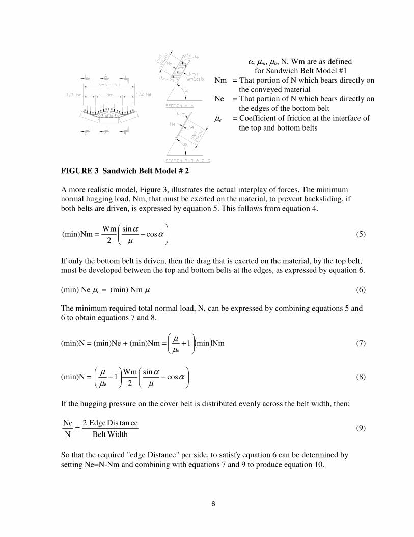
FIGURE 3 Sandwich Belt Model # 2 A more realistic model, Figure 3, illustrates the actual interplay of forces. The minimum normal hugging load, Nm, that must be exerted on the material, to prevent backsliding, if both belts are driven, is expressed by equation 5. This follows from equation 4.
���
����
�−= α
µα
cossin
2Wm
Nm(min) (5)
If only the bottom belt is driven, then the drag that is exerted on the material, by the top belt, must be developed between the top and bottom belts at the edges, as expressed by equation 6. (min) Ne µe = (min) Nm µ (6) The minimum required total normal load, N, can be expressed by combining equations 5 and 6 to obtain equations 7 and 8.
(min)N = (min)Ne + (min)Nm = ( )Nmmin1e
���
����
�+
µµ
(7)
(min)N = ���
����
�−��
�
����
�+ α
µα
µµ
cossin
2Wm
1e
(8)
If the hugging pressure on the cover belt is distributed evenly across the belt width, then;
WidthBeltcetanDisEdge2
NNe = (9)
So that the required "edge Distance" per side, to satisfy equation 6 can be determined by setting Ne=N-Nm and combining with equations 7 and 9 to produce equation 10.
α, µm, µb, N, Wm are as defined for Sandwich Belt Model #1
Nm = That portion of N which bears directly on the conveyed material Ne = That portion of N which bears directly on the edges of the bottom belt µe = Coefficient of friction at the interface of the top and bottom belts

7
���
����
�+
=
µµe
12
WidthBeltcetanDisEdge (10)
If µ =µe, then the required Edge Distance per side is ¼ belt width. If contaminants or fine grains of material lubricate the edges, then µe may be much less than µ . If µ e=µ/2 then Edge Distance per side equal to 1/3 belt width is required to transfer the needed drag from the bottom belt edges to the top belt and material interface at the center. Effectively only 1/3 belt width is used to carry the material. Actual internal friction coefficients vary at the materials and belt surface interface, from less than .6 to above .9. Some vary fine materials tend to fluidize and have no internal friction. These cannot be conveyed. Wider variation occurs at the belt edges, depending on the degree of wetness and contamination. Friction coefficients can vary from less than .1 to above .5. Drag transfer at the edges is not necessary if the hugging pressure over the material is twice that determined in equation 5 or if both top and bottom belts are driven. Driving both belts is in general the better solution since it avoids the need for higher hugging pressures that will cause greater loads on the conveyor components. Driving both belts also results in higher possible lifts, since the tension capacity of both belts is exploited, and there is no differential stretch or movement between the two belts. Since hugging pressure is in general distributed evenly, along the belt length and across the belt width only a portion of the applied hugging load is actually transmitted to the conveyed material with the remainder serving as belt on belt edge seal pressure. Furthermore, the above equations to determine hugging pressure must be satisfied at any rate of loading, from empty to design load to severe overload that will cause leakage. The ratio of the material-hugging load (Nm) to the total applied hugging load (N) is known as the Hugging Factor (HF). HF must be determined by layout, for each belt width and idler selection, as a function of cross-sectional filling area. Figure 4 illustrates the necessary layouts to determine HF. Figure 5 shows graphically a sample relation between HF and cross-sectional filling area.
FIGURE 4 Sandwich Belt Cross-Sects for Rates through severe overload
FIGURE 5 Sandwich Belt Hugging Factors for Varying Degrees of Loading
Having determined (min)Nm, by equation 5 then;
0.3
0.4
0.5
0.6
50 100 150 200 250
% of Design Area
Hug
ging
Fac
tor

8
HFNm(min)
N(min) = (11)
This is regardless of driving or belt edge considerations. Equation 8 serves merely as a check in the case of driving only one belt. Support, suspension and hugging of the load Referring to Figure 1, the Expanded Conveyor model allows for locating the idlers below or above the belt line, supporting it and its load in the former and holding it against uplift in the latter. Conventional conveyor technology addresses the case of uplift and how to limit it. The Expanded Conveyor Technology also addresses the case of support against uplift and insuring that the load will not sag away from the inverted support curve.
1. Loading onto bottombelt between skirts
2. Top belt joins bottom beltto sandwich material
4. Inflection 1 betweencurves 1 and 2
3. Curve 1, bott belt hugsmtl against top belt
5. Inflection 2 betweencurves 2 and 3
6. Inflection 3 betweencurves 3 and 4
7. Material dischargefrom between belts
1
2
3
4
5
6
7
FIGURE 6 Sample Profile and Details of Sandwich Conveyor that uses only radial pressure due to tension to naturally induce the hugging pressure

9
The hugging load as computed in equations 5 and 11 may be induced naturally, by radial pressure due to tension, or may be applied by an external mechanism. Frizzell et al. 1981 and Dos Santos and Frizzell 1983 suggest various manners of applying hugging pressure including "spring loaded equalized pressing modules with closely spaced rolls" and air pressure through a plenum. Figure 6 shows the profile and details of a sandwich belt conveyor (the DSI Snake Conveyor) that uses only radial pressure due to tension, to naturally induce the hugging pressure. Radial Loads and Suspension. Material is loaded onto the bottom belt of the Sandwich Belt High Angle Conveyor at a low angle in a manner similar to a conventional conveyor. Proceeding along the conveyor profile, the top belt joins the bottom belt at the sandwich entrance and with the material between them the conveying angle is increased to the high conveying angle. Standard fabric belts and some special steel cord belts (of low modulus), when designed to the radius of curvature constraints of conventional conveyors (described later in this writing), will permit transition curves of short radius without overstressing the belt edges or buckling the center. As the belts follow the vertical transition curve, a radial inward load is induced according to the equation:
Pr = TR
(12)
where: T = Belt tension at the point in question along the conveyor profile. R = Radius of curvature corresponding to belt tension T. Pr = The corresponding lineal load induced by the belt or belts of tension T. Accurate analysis of the belt tension and control of the profile geometry, to induce the desired radial load while adhering to the radius of curvature constraints, is critical to success of the design. Radial load requirements can be described as follows: From the last support idler of the loading area to the sandwich entrance, the bottom carrying belt is suspended while supporting its own weight plus the conveyed material load. If a circular arc approximates this suspension profile, then the induced radial pressure must satisfy equation 13. Prb = Wm + Wb (13) where: Wm = Lineal weight of the conveyed material. Wb = Lineal weight of the bottom carrying belt. Prb = Radial load induced by the bottom belt as determined from equation 12. For the predetermined minimum radius of the sag curve the bottom belt tension, Tb, must satisfy equation 14.

10
Tb ≥ R(Wm + Wb)SF (14) where: R, Wb, are as previously defined. Wm is the conveyed load at the design maximum conveying rate. SF = Safety Factor against possible overload. SF = 1.5 is recommended. Proceeding along the conveyor profile beyond the sandwich entrance, the induced radial load by the bottom belt, must be sufficient to counter-act the radial components of the bottom belt and conveyed material weights in addition to providing the hugging pressure to prevent material slide back at the high conveying angle α.
ααcosWb
HFcosWmNm
P br ++≥ (15)
where: Prb, Wm, Wb are as previously defined. Nm = Lineal hugging load on the conveyed material as determined by equation 5 HF = Hugging Factor according to the graph of Figure 5. Equation 15 must be satisfied throughout the transition curve up to the first inflection zone. Above the first inflection zone the sandwich conveyor profile reverses curvature with the top belt providing the required hugging load by radial pressure. The resulting Prt must then satisfy equation 16.
αcosWtHFNm
P tr −≥ (16)
where: Nm and HF are as previously defined. Prt = Radial load induced by the top belt as determined from equation 16. Equation 16 must be satisfied throughout the profile curve between the first and the second inflection zones or until discharge (if the profile is of simple s-shape with a high angle discharge). Subsequent curves are treated similarly. Continuity of Hugging. Because we are conveying and elevating bulk materials all of the preceding equations assume that the conveyed material has an internal friction and that the hugging pressure is transferred evenly and uniformly onto the bulk material. Thus the manner of applying the hugging pressure must be even and uniform and its application must be by and through a medium that hugs the entire bulk material surface without lapse. Internal hugging will be by the interaction of the conveyed particles. Radial pressure due to tension is ideal, in this regard, when idler support spacing is sufficiently close and the hugging belt is sufficiently pliable to properly surround and hug all of the surface material.

11
Load Support, Troughability and Pliability The term pliability is not common in belt conveying but troughability is. In the conventional conveyor technology a conveyor belt must have the proper balance of transverse stiffness and flexibility in order to function properly. The former, commonly referred to as "load support", insures that the belt will easily support the load without excessive creasing that could lead to fatigue failure, especially at the idler junction. The latter, "troughability" insures that the belt will not bridge over the center roll when the conveyor is running empty. In fact the "troughability" criteria must insure that the belt makes good contact with all three idler rolls. Poor "troughabilty" will result in a conveyor whose belt is not trainable thus experiencing excessive downtime (due to tripping of alignment switches), belt edge damage and spillage at transfers. It is this writer's experience that, in general, belt manufacturer's "troughability" ratings are not conservative. The Expanded Conveyor Technology introduces "Pliability" another measure of transverse flexibility. This is akin to "troughability" and insures that the belt will make good uniform contact with the surface of the conveyed material. Indeed the material's surface topography will define the topography of the hugging belt. It is this writer's experience that the "troughabilty" criteria nearly satisfies the "Pliability" requirement and that the next, more flexible belt, on the "troughability" table, will conservatively satisfy the pliability requirement. The properties discussed are transverse to the conveyor's length. Ideally these should be determined separately from the conveyor's longitudinal strength and stiffness. Unfortunately, in standard multi-ply belts, these are tied to the longitudinal strength, which is increased, with added plies of a standard strength class. When high belt tensions are produced at narrow belts not much can be done to reduce the transverse stiffness of the required multi-ply belt. It may be necessary to use a belt that is wider than the volumetric rate requires. At the other extreme, when only low tensions are produced at very wide belts, it behooves us to achieve good load support without greatly increasing the belt strength thus its axial stiffness. There is much more than an economic incentive as will be seen later. Load support can be achieved by increasing the carcass thickness with added rubber between the plies. It is not uncommon to use a 2-ply belt of 1800mm (72") belt width. Experience shows that load support can be achieved by matching the carcass thickness with that of the correct belt tabulated, regardless of the number of plies. CAPACITY, MATERIAL SIZE, BELT SPEED, BELT WIDTH In principal sandwich belt conveyors are not limited in belt width or in throughput capacity. Practically, belting, idlers and pulleys are available up to 3048 mm (120 inches) wide in the English system and up to 3200 mm (126 inches) wide in the metric system. Such belt widths make possible very high conveying rates. Most throughput requirements are met with sandwich belt conveyors in the 600 mm (24 inch) to 2200 mm (84 inch) belt width range.

12
Lump Size Sandwich Belt Conveyors can handle very lumpy materials because the belt sandwich is totally conforming to the natural material cross-section. The material hugging load is by radial pressure due to tension. Local uplift, or punching, by a single lump is not countered by a high local loading over that lump. Protruding lumps, however, can define their shape very distinctly when surrounded by belts that are too thin, resulting in impact on successive idlers, when the belt speed is high. It is important therefore to choose belts of a thickness appropriate to the severity of the application. The sandwich belt high angle conveyor must be designed to run continuously and is expected to operate thousands of hours without the need to replace belting or idlers. The lump size distribution that a sandwich conveyor can handle, on this basis, is dependent on the ruggedness of the belts and idlers and on the operating belt speed. TABLE 1 Lump Size Criteria for DSI Snake Sandwich High Angle Conveyor
Metric Units English Units BELT
WIDTH Max. Size
> 10% Lumpy Mtl.
Max. Size < 10%
Lumpy Mtl.
BELT WIDTH
Max. Size > 10%
Lumpy Mtl.
Max. Size < 10%
Lumpy Mtl. (mm) (mm) (mm) (inches) (inches) (inches)
600 68 86 24 2.7 3.4 700 80 100 30 3.4 4.3 800 91 114 36 4.1 5.1 900 103 128 42 4.8 6.0
1000 114 143 48 5.5 6.8 1200 137 171 54 6.2 7.7 1400 160 200 60 6.8 8.6 1600 182 228 66 7.5 9.4 1800 205 257 72 8.2 10.3 2000 228 285 78 8.9 11.1 2200 251 314 84 9.6 12.0 2400 274 342 90 10.3 12.8 2600 296 371 96 10.9 13.7 2800 319 399 102 11.6 14.5 3000 342 428 108 12.3 15.4 3200 365 456 114 13.0 16.2
120 13.7 17.1
Based on 20° troughing idlers, appropriate belt speed and employing suitable conveyor hardware. Table 1 lists the recommended maximum lump size, as a function of belt width for a predominantly lumpy material and for a material that has only occasional lumps, less than 10% of the total throughput. The former maximum lump size is limited not to exceed the trough depth of a belt carried on three-equal-roll, 20° troughing idlers. The latter is increased

13
by 25% to reflect the lower duty requirements of having only occasional lumps. These recommendations assume belt speeds according to the guidelines of table 2. Furthermore, the quoted maximum "lump size" means that all lumps will pass through a grizzly of "lump size" by "lump size" opening and the length will not exceed the "lump size” by more than 50%. The open side setting of a crusher does not meet these criteria since it will insure only the least dimension of the lump. Various materials will therefore require different crusher settings, in general, less than the recommended "lump size". These recommendations are consistent with the continuous duty requirement. Experience has revealed that a sandwich belt conveyor to handle lumpy material must be designed accordingly, using thick belts and heavy-duty idlers. Furthermore, all carrying idlers along the transition curves must have a center impact roll and two steel wing rolls. The former minimizes any dynamic effects due to the lump shapes defined along the profile and the latter provide belt support so that the center rolls will not wear out prematurely. Other lump size consideration including transfer points and associated impact forces and the possibility of large lumps jamming at loading skirts are not different than conventional conveyor considerations. Capacity and Load Cross-Section The design load cross-sectional area must leave sufficient edge distance to insure no material leakage even with off-centered loading and maximum operating misalignment between the two belts. Figure 4 shows eight (to scale) cross-sectional layouts, at four different degrees of filling. These are shown, at the inverted idlers and at the upright idlers, to reflect support along the first and the second transition curves. Study and experience has revealed that the cross-sectional filling area of the second layout is a good basis for the design load when it is augmented by upgrading and de-rating factors that are related to the conveying angle, the idler troughing angle and the conveyed material. Belt Speed TABLE 2. General Recommended Max. Belt Speeds.
Metric Units English Units Material being conveyed Belt speeds
(m/s) Belt Width
(mm) Belt speeds
(fpm) Belt Width
(Inches) Grain or other free-flowing non-abrasive material
2.5 3.5 4.0 5.0
450 600-750 900-1050
1200-2400
500 700 800
1000
18 24-30 36-42 48-96
Coal, damp clay, soft ores, overburden and earth, fine-crushed stone
2.0 3.0 4.0 5.0
450 600-900
1050-1500 1800-2400
400 600 800
1000
18 24-36 42-60 72-96
Heavy, hard, sharp-edged ore, coarse-crushed stone
1.8 2.5 3.0
450 600
Over 900
350 500 600
18 24
Over 36

14
The rules regarding operating belt speed are the same as for conventional conveyors. This is logical since Snake Sandwich Conveyors use all conventional conveyor components and follow the same rules with regard to belt tension rating and operating safety factor, and with regard to idler loads and rotational speed. Table 2 serves as our guide to selecting belt speeds that are generally appropriate for the cited applications. RADIUS OF CURVATURE CONSTRAINTS Long Transition Curves and Uplift Concave and uplift curves as addressed in the Conventional Conveyor Technology make no allowance for incline angle and don't consider a top belt riding on the material or on the bottom belt (when running empty). Indeed the conveying angle may be increased to nearly that of the material's internal friction angle merely by adding a cover belt to steady the material's surface. Satisfying the general equation 17 will preclude uplift.
αcos)WmWb(RT
Pr +≤= (17)
Minimum uplift radius is obtained by solving for R:
αcos)WmWb(T
R+
≥ (18)
Equation 18 must be satisfied for the top belt only and for the combined top and bottom belts only. T is the maximum possible tension sum under the corresponding operating conditions (likely during starting). Constraints on Vertical Radius of Curvature
FIGURE 7 Stresses on a section that is subject to simultaneous tension and bending
fa = ATc
N.A. = Neutral Axis of Section Tc = Axial Tension (kN)(lbs) R = Radius of Curvature (m)(ins) A = Cross-Sectional Area (m2)(in2) M = Bending Moment (m-kN)(in-lbs) I = Section Moment of Inertia (m2)(in2) fa = Axial Stress (kN/m2)(lbs/in2) fm = Bending Stress (kN/m2)(lbs/in2) f = Combined Stress (kN/m2)(lbs/in2) y = Distance from N.A. (m)(ins)
fm =I
My f = fa + fm =
IMy
ATc +

15
FIGURE 8 Idealization of a multi-ply belt carried on three-equal-roll troughing idlers The equations to determine the minimum allowable vertical radius of curvature are in the conventional conveyor technology and derived here from basics. This is to reveal the underlying principles and to extend their applicability. The vertical belt curve must be designed so that it will not cause buckling nor overstress at any part of the belt cross section. When any section of linearly elastic material is subject to simultaneous tension, Tc, and bending, M (which is induced by the curvature l/R as shown in Figure 7), the stresses due to the independent forces may be superimposed. The model assumes that the curve is smooth and that plane sections remain plane. This model can be applied along the transition curve of a conveyor belt, at points sufficiently far from the ends, if the trough depth and width are much less than the radius of curvature and the support idlers are very closely spaced. Having made these assumptions, the bending moment can be related to the radius of curvature by the following equation:
RIE
M = (19)
where: E = modulus of elasticity (kN/m2)(lbs/in.2) I = sectional moment of inertia (m4)(in.4) and M and r are as defined in Figure 7. Superposition of stresses may then be expressed as follows:
yRE
AT
fffc
ma +=+= (20)
where: f, fa, fm Tc, A, R and y are as defined in Figure 7. This equation can be applied to a multi-ply conveyor belt of arbitrary geometry by making the following substitutions: • Replace the cross-sectional area A (m2)(in.2) in equation 20 by the product of the belt
width and the number of plies, (b) by (p) (m-ply)(in.-ply). • Replace the elastic modulus E (kN/m2)(lb/in.2) by the commercially listed belt modulus
Bm (kN/m-ply)(lbs/in.-ply).
b = Belt Width φ = Troughing Angle p = Number of Plies N.A. = Neutral Axis

16
Equation 21 then follows from equation 20.
yR
Bmpb
Tfff
cma +=+= (kN/m-ply)(lbs/in-ply) (21)
Our maximum and minimum stress criteria is taken from Goodyear 1982. We will limit the
maximum combined stress to 1.15 pb
Tr and the minimum to
pbT05. r
. The former is reasonable
as the increased allowable is local and the safety factors against breaking, typically 8 to 14, are only slightly reduced. The latter insures that slack belt does not occur, even locally. The minimum tension resists local knuckling of lumps into the belt. To limit the maximum local stress, at the outer fibers, the following equation must be satisfied.
'yR
Bmpb
TpbT15.1 cr +≥ (22)
where: Tr = Working tension rating of the entire belt (kN)(lbs.) y' = distance from the neutral axis N.A. to the extreme outer fibers (m)(in.) Solving for R yields the following:
cr TT15.1'ypBmb
R−
≥ (23)
To maintain the minimum tension at the inner fibers, the following equation must be satisfied:
"yR
Bmpb
TpbT05. cr −≤ (24)
where: y" = distance from the neutral axis N.A. to the extreme inner fibers (m)(in.) Solving for R yields:
rc T05.T"ypBmb
R−
≥ (25)
Next, consider a belt that is carried on three-equal-roll idlers of troughing angle φ. The belt is assumed divided into three equal parts, as illustrated in Figure 8.

17
If the vertical curve under consideration is concave (that is, belt edges are at inner side of curve), then y'=(b/9)sinφ and y"=(2b/9)sinφ. Equations 26 and 27 follow when these identities are substituted into equations 23 and 25, respectively. If a convex vertical curve is considered (belt edges are at the outer side of the curve), then y'=(2b/9)sinφ and y"=(b/9)sinφ. Equations 28 and 29 follow when these identities are substituted into equations 23 and 25 respectively. Curvature Constraint Equations
)TT15.1(sinpBm
9b
Rcr
2
−≥ φ
(To prevent overstress of middle when curve is concave) (26)
)T05.T(sinpBm
9b2
Rrc
2
−≥ φ
(To prevent edge buckling when curve is concave) (27)
)TT15.1(sinpBm
9b2
Rcr
2
−≥ φ
(To prevent edge overstress when curve is convex) (28)
)T05.T(sinpBm
9b
Rrc
2
−≥ φ
(To prevent buckling of center when curve is convex) (29)
Curvature constraint equations 26, 27, 28 and 29 apply to multi-ply fabric belts. For steel cord or single ply belts the equations are applicable by setting the number of plies p=1. In the English system it is typical to input the belt width-b in inches and to divide the right side of equations 26-29 by 12 so that R will be in feet rather than inches. Transition Curves, How Tight Can They Be? Equations 26 through 29 reveal the governing parameters as they relate to the allowable radius of curvature. The belt width, b, and the troughing angle, φ, are typically established ahead of time for the capacity lump size requirements. The remaining variables are the composite elastic modulus of the belt, Bm p (kN/m)(lb/in.), the rated working tension, Tr (kN)(lbs), and the operating belt tension at the point considered, Tc (kN)(lbs). For a concave curve, equations 26 and 27 must be satisfied simultaneously. Tc may be increased by an increase in take-up tension, to counteract the buckling tendency, but not to the point of exceeding the working tension rating, Tr, on the average, or by more than 15% at the extreme fibers. The same arguments apply to equations 28 and 29 for convex curves. To minimize the radius of curvature without violating the governing equations, we must seek a belt which maximizes the ratio of the rated tension to the elastic modulus (maximize Tr/Bm-p). The nylon-by-nylon reinforced fabric belts offer the best solution of the commercially available multi-ply fabric belts. Equations 26 - 29 reveal that as the troughing angle goes to zero (a flat belt) then R(min) also goes to zero. In fact before reaching this point we must analyze the sectional properties of the flat belt according to its through thickness construction as when determining the minimum

18
allowed pulley diameter. However, a flat sandwich belt has no carrying capacity and no tolerance for lumps of any size. Between the typical 20° troughing angle and flat belt there is cause for consideration. With the proper adjustments for capacity and lump size sandwich conveyors having very tight transition curves using 10° and even 5° troughing idlers are practical and many are in operation. POWER, TENSION, TRACTION, LOAD SHARING The sandwich belt tension and power calculations are derived from the rules for conventional conveyors. Driving resistances due to elevating material, pulley friction, skirt-board and edging friction, material acceleration, belt scrapers and plows and other accessories, are indeed identical to those of conventional conveyors. Idler rolling resistance, due to seal and bearing friction, is also the same as for conventional conveyors, but the latter requires an accurate accounting of all sources of bearing loads under all possible loading conditions. Radial loads, due to belt tension, are significant, whereas in conventional conveyors, the lineal load increase at convex curves is typically ignored as is the lineal load decrease at concave curves. On the other hand only the normal component of the material and belt weights exert a load on the roll's bearing, causing a friction. It is the area of belt and material flexure and shearing and the belt on idler roll imprint resistances which requires a fundamental understanding before determining the true form of their applicability to sandwich belt high angle conveyors and to curves in general. Basic Power Requirements Following the basic approach established by CEMA 1994, power requirements are calculated after determining the effective driving tensions Tte and Tbe for the top and bottom belts respectively. In order to illustrate and adapt the familiar CEMA formulas the units required for this section will be according to the English system. It is only a matter of conversion to express these in the metric system. Drive pulley shaft horsepower is determined using equation 30.
000,33VT
HPse= (30)
where: HPs = Drive pulley-shaft horsepower Te = Tte or Tbe (lbs) V = Belt speed (feet per minute -FPM) Additional drive train losses must be added to HPs to obtain the required motor horsepower. Drive Tension Te, Belt Line Resistances

19
According to CEMA 1994, page 73 the total conveyor travel resistance, the required driving tension Te is: Te = L Kt (Kx + Ky Wb + .015 Wb) + Wm (L Ky ± H) + Tp + Tam + Tac (31) Where: L = Length of the conveyor H = Vertical distance that the material is lifted or lowered Wb = Lineal Weight of the belt Wm = Lineal weight of the conveyed material Kt = Ambient temperature correction factor Kx = Idler bearing and seal resistance
Ky = Belt travel resistance coefficient associated with: 1. Indentation of the idler rolls into the belt cover and 2. Shear and flexing of the belt and material as it travels over each idler.
Ky is assigned the value .015 for the return flat belt. Tp = Pulleys' resistance to rotation Tam = Force to accelerate the material Tac = Resistance from accessories Furthermore Kx and Ky are defined in CEMA 1994, pages 76 and 77.
( )SiAi
WmWb00068.Kx ++= (32)
( ) B01.WmWbA0001.Ky ++= (33) Where:
Ai = Idler's rolling resistance without any load, commonly referred to as the seal resistance (lbs)
Si = Idler Spacing (ft) A, B Values are tabulated in CEMA 1994, page 81 Table 6-4. These values are
tension and idler spacing dependent. The value of A varies dramatically, inversely with tension, but only modestly with idler spacing. The A value is generally acknowledged as a coefficient of the flex and shear resistance. The B value is generally acknowledged as a coefficient of the belt on roll imprint resistance. To focus only on the belt line resistance, equation 31 is rewritten to consider only a unit length of the belt line. Unit Te = Kt (Kx + Ky Wb) + Wm (Ky ± H) (34) Where: Ky = .015 for the return belt

20
Kx Value is split for the Carrying and return belt Equations 32-34 don't acknowledge incline angle or belt line resistances associated with induced or applied lineal forces or the flexing and shearing due to curvature. We generalize equations 32-34 for the "Expanded Conveyor Technology".
( )SiAi
PR
TcosWmWb00068.Kx +
���
�
�+±+=
α (35)
Ky = KyA + KyB = ( ) B01.PR
TcosWmWbA0001. +
���
�
�+±+
α (36)
UnitTe=Kt(Kx+KyA Wb )+Wm(KyA ± H)+ ( )���
�
�+±+
PR
TcosWmWb α KyB (37)
Equations 34-37 are applicable for carrying and return belts and also apply to a horizontally curving conveyor. The KyA values will vary for the various degrees of belt troughing and for the belt section about a vertical axis. Kx. Kx, as expressed in equation 35, merely accounts for all sources of loading on the belt line and removes the tangential component of the material weight. It also allows for multiple belts sharing a common belt line and idler support. When only one conveyor is considered, α is set to zero and there is no added radial or applied pressure, equation 35 reduces to equation 32 which is according to CEMA. Ky. Ky is first divided into two parts. KyA is related to the shear and flex of the material and belt. KyB is related to the belt on roll imprint resistance. We restate KyA apart:
KyA= ( )���
�
�+++
PR
TcosWmWbA0001. α (38)
We refer to the value in the brackets as a "derived load equivalent -WEQ". Derivation shows that the belt-line deflection or material and belt deformation, over each successive idler, caused by the conveyor loading and the curved profile is identical to a material and belt load =WEQ on a straight profile. This identity is essential for the validity of the "expanded" equation 36 and 37. KyB is the second term of the Ky formula and this is not changed. The "expanded Ky" makes the same allowances as does the "expanded Kx" and similarly reduces to equation 33 when considering a single horizontal non-curving conveyor. Unit Te. The "Expanded Unit Te" treats + WmWb as a measure of resistance to deformation when multiplied by KyA and as true lineal weights when multiplied by H and by KyB. Again the derived load equivalent -WEQ is multiplied by KyB, a measure of the imprint

21
resistance. Equation 37 reduces to equation 34 when α is zero and there are no radial loads on a single conveyor. Te, Load Sharing, Traction How will multiple belts on a common belt line share the increase in tension? If there is no relative slip between them then they will share it in proportion to their relative axial stiffness. At the ideal load sharing ratio a minimum hugging pressure will insure no relative slip. Economics always dictates a less than ideal load-sharing ratio. For small sandwich-belt conveyor units it is common to drive only the bottom belt. In such a case equation 2 or equation 8 must be satisfied plus additional traction must be developed, by hugging pressure, to overcome the belt-line resistances acting on the top belt. There will be minor relative slip as the bottom belt strain will be higher than that of the top belt. For larger sandwich belt conveyors load sharing drives are used to exploit the strength of both belts. Sharing is typically equal, not ideal, as this optimizes economy. In such a case the top belt hugging pressure must satisfy equation 5 and must be increased as required to develop the additional driving traction of the top belt. SUMMARY AND CONCLUSIONS Sandwich Belt Conveyors and Beyond The challenge of developing the sandwich belt conveyor technology within the context and according to the rules of conventional conveyors led the writer to generalize the conventional conveyor technology. This, the "Expanded Conveyor Technology" has demonstrated its adaptability to sandwich belt conveyors, essentially using proven principles and equipment that is technologically and commercially mature. In so doing, the risk was minimized and operating characteristics were predictable. Similarly, these principles apply to variations of multiple conveyors such as two-way, horizontally curving, multi-boosted conveyors, using belt-on-belt or tripper boosters. Figure 1 demonstrates but doesn't exhaust the possibilities. Status of the Expanded Conveyor Technology Clearly, sandwich belt conveyors, as a part of the Expanded Conveyor Technology, have reached maturity. The hugging pressure, capacity, curvature constraints, and power calculations have all been demonstrated to be valid by experience and field monitoring. In the late 1980's the Expanded Conveyor Technology was employed to develop a successful program for belt-on-belt type booster drives. Constraints on the shared belt-line varied from complete tension development, at the booster belt, to only partial shear development, depending on the material load over the booster belt. Presently the writer is extending these principles to conventional conveyors in order to produce a more complete analysis. The "DSI Expanded Conveyor Technology" computer program has produced analytical results (see Figure 9) that correlate very well with field

22
monitoring of the conveyors analyzed. Additionally the program allows the user to input discretionary factors that will further calibrate the analysis model.
Belt Width: 36 ins Conveyor Length: 9250 ft Lift: 77.5 ft
Belt Wt: 13.7 lbs/ft Idler Spacing: 5 ft - Trouh 10 ft - ReturnCONVEYING RATE: 1800 STPH BELT SPEED: 750 FPM
-17.5999822
87.73155948
Conveyor Profile
0
500
1000
1000 2000 3000 4000 5000 6000 7000 8000 9000 10000 11000 12000
Tensions Running Loaded
0
10000
20000
30000
40000
50000
60000
1000 2000 3000 4000 5000 6000 7000 8000 9000 10000 11000 12000
Take-Up Movement(Feet)
0 10 20 30 40 50
1-100
0100200300400500
1
-1000
100200300400500
1
PrimaryDrive HP
BoosterDrive HP
LOAD
UNLOAD
FIGURE 9 The Expanded Conveyor Technology program produces real time analysis. By using "LOAD" and "UNLOAD" buttons the most aggravated loading conditions can be simulated quickly. What remains for the future? Much remains for the future. The framework for the Expanded Conveyor Technology is illustrated in Figure 1 and outlined in this writing. Its application is proven in the areas mentioned yet many formulations are largely empirical and extrapolated. Industry and academia are hereby invited to scrutinize this writing's various proposals, derivations and observations and to make their contribution to the Expanded Conveyor Technology. It is our hope, in the coming years, that we will work together to expand the conventional conveyor technology unifying all conventional and non-conventional conveyors according to common, proven principles and formulas.
OL Conveyor with Primary Drive and "Smart Booster"
Loaded Downhill Sections

23
REFERENCES Conveyor Equipment Manufacturers Association-CEMA. 1994. Belt Conveyors for Bulk
Materials - Fourth Edition. Dos Santos, J. A. and E. M. Frizzell. 1983. Evolution of Sandwich Belt High-Angle
Conveyors. CIM Bulletin. Vol 76, No. 855:51-66 Frizzell, E. M., E. A. Mevissen, and A. C. Siminerio. 1981. Trucks versus High-Angle
Conveyor Haulage in Open Pit Mines. Mining Congress Journal - October. Goodyear Handbook of Conveyor and Elevator Belting. 1982. The Goodyear Tire and
Rubber Company. Akron, Ohio.