theory on wiring large systems - victron energy...theory on wiring large systems. high power...
TRANSCRIPT

Theory on wiring large systems
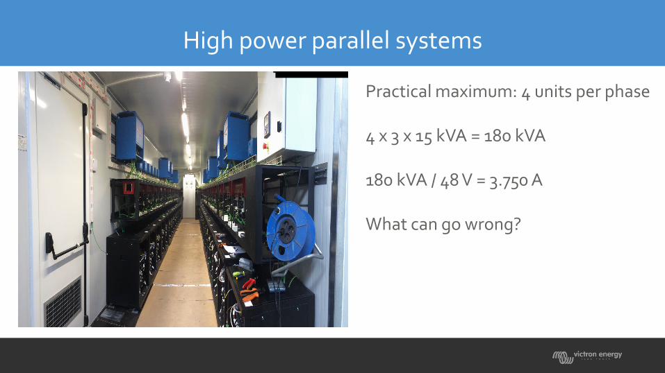
High power parallel systems
Practical maximum: 4 units per phase
4 x 3 x 15 kVA = 180 kVA
180 kVA / 48 V = 3.750 A
What can go wrong?
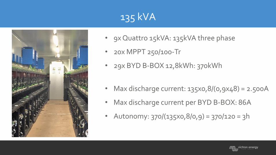
135 kVA
• 9x Quattro 15kVA: 135kVA three phase
• 20x MPPT 250/100-Tr
• 29x BYD B-BOX 12,8kWh: 370kWh
• Max discharge current: 135x0,8/(0,9x48) = 2.500A
• Max discharge current per BYD B-BOX: 86A
• Autonomy: 370/(135x0,8/0,9) = 370/120 = 3h

DC, inverting
When Victron Quattros, Multis or inverters operate in parallel, one unit has to be set as master, and the others are slaves (VE.Configure).
The master sets the PWM pulse width for the slaves.This means that all units will have the same DC to AC transfer function
Vout = α(Vin - Rin*Iin) with α = Iin / Iout
α is determined by the PWM modulation and the winding ratio of the transformer.α therefore is identical for all paralleled units.
The internal resistance referenced to the input Rin is also identical for all paralleled units.

Vout = α(Vin - Rin*Iin)
When the outputs are wired in parallel, Vout is the same for all units.What happens when Vin is different from one unit to another?
The only variable left is the unput current Iin.
Therefore, if Vin is different from one unit to another, Iin must also be different.For a quantitave approach we need to now Rin.
Rin can be derived from the efficiency (η)

Pout = Pin – Rin*Iin²
Rin can be derived from the efficiency (η):
Pout = Pin – losses = η*Pin = Pin – (1-η)*Pin = Pin – Rin*Iin²
And therefore:Rin = (1-η)*Pin / Iin² = (1-η)*Vin / Iin
The full load efficiency of a Quattro 15kVA is 96%, therefore Pout = 0,96*Pin
If Pout = 15*0,8 = 12kW, the input power is 12 / 0,96 = 12,5kW. Losses = 500W .
And: Rin = (1-0,96)*50 / (12,5 / 50) = 8mΩ

Pout = Pin – Rin*Iin²
Now we can derive a formula for the output power unbalance of two paralleled units connected to the battery with different cable resistance (= different cable length).
Vout = α(Vin1 - Rin*Iin1) = α(Vin2 - Rin*Iin2)
Including cable resistance R1 and R2:
Vin2 + R2*Iin2 = Vin1 + R1*Iin1
And therefore:Iin2 / Iin1 = (R1 + Rin) / (R2 + Rin)

Iin2 / Iin1 = (R1 +Rin) / (R2 +Rin)
Rin = 8mΩ
This means that if two units are paralleled and the cable resistance is << 8mΩ, a difference of 0,16mΩwill result in a power unbalance of 2%.
And the resistance of 95 mm² copper cable is 0,18mΩ per meter.....
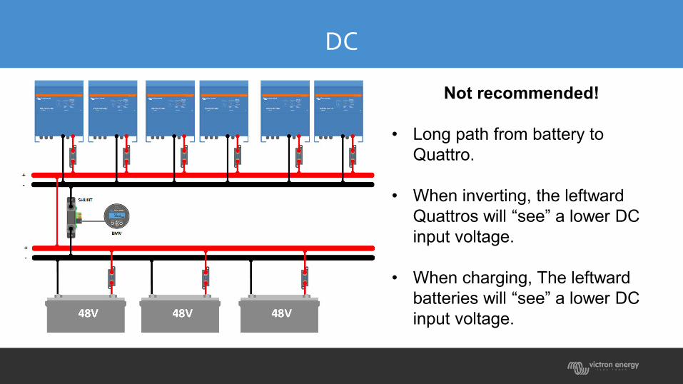
DC
Not recommended!
• Long path from battery to Quattro.
• When inverting, the leftward Quattros will “see” a lower DC input voltage.
• When charging, The leftward batteries will “see” a lower DC input voltage.

DC
Recommended

Output resistance
The internal resistance can also be referred to the output:
The output to input resistance ratio is:
Rout = ((1-η) / η)*Vout / Iout
Which for a 15kVA Quattro results in:
Rout = 180mΩ
This means that if two units are paralleled, a difference of 3,6mΩwill result in a power unbalance of 2%.
And the resistance 0f 10 mm² copper cable is 1,6mΩ per meter.

Output resistance
Recommendation:
Use AC cables of similar length.
But do not try to solve the problem by increasing the cross section of the AC cabling!

Backfeed contactors in parallel
But do not try to solve the problem by increasing the cross section of the AC cabling!
Small differences in the internal resistance of in particular the backfeed contactors may result in AC current being diverted fron one unit to another.
The voltage drop tolerance of a 100A backfeed contactor is about 20mV at 100A. The total cable resistance (input + output) should therefore be larger than R = 60mV/100A = 6mΩ.

Backfeed contactors in parallel

Bypass switch and input voltmeters
Low AC input cut-off
The default low voltage cut-off is 180 VAC.
When a genset runs down, the voltage and frequency will gradually decrease.
To prevent overloading the backfeed contactors we recommend to increase the the low voltage cut-off to 200 VAC.
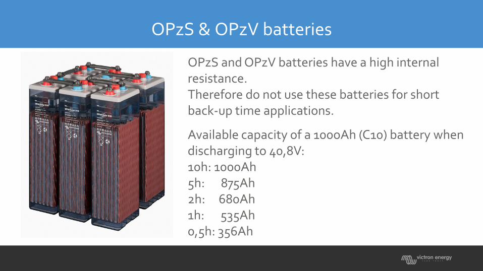
OPzS & OPzV batteries
OPzS and OPzV batteries have a high internal resistance.Therefore do not use these batteries for short back-up time applications.
Available capacity of a 100oAh (C10) battery when discharging to 40,8V:10h: 1000Ah5h: 875Ah2h: 680Ah1h: 535Ah0,5h: 356Ah