thermal analysis of cl-talon cladding support...
TRANSCRIPT
Report Number: 180181400
February 16, 2018
Morrison Hershfield | Suite 310, 4321 Still Creek Drive, Burnaby, BC V5C 6S7, Canada | Tel 604 454 0402 Fax 604 454 0403 | morrisonhershfield.com
Thermal Analysis of CL-TALON
Cladding Support System
Presented to:
CL-TALON
3223 Dell Ave.
North Bergen, NJ 07047
TABLE OF CONTENTS
Page
Thermal Analysis of CL-TALON Cladding Support System MH ref: 180181400
1. INTRODUCTION AND BACKGROUND 1
2. MODELLING PROCEDURES 3
3. THERMAL RESULTS – STEEL STUD BACKUP WALL 4
4. ENERGY CODE COMPLIANCE 5
5. CONCLUSIONS 7
APPENDIX A – MODELLING PARAMETERS AND ASSUMPTIONS
APPENDIX B – ASSEMBLY INFORMATION AND MATERIAL PROPERTIES
APPENDIX C – SIMULATED TEMPERATURE PROFILES
APPENDIX D – ASHRAE 90.1 PRESCRIPTIVE PATH COMPARISON

- 1 -
Thermal Analysis of CL-TALON Cladding Support System MH ref: 180181400
1. INTRODUCTION AND BACKGROUND
Morrison Hershfield was contracted by CL-TALON to evaluate the thermal performance of their CL-Talon 300 Cladding Support System for various configurations. This report is a summary of the analysis.
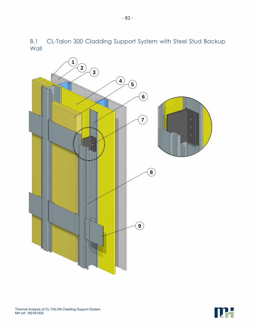
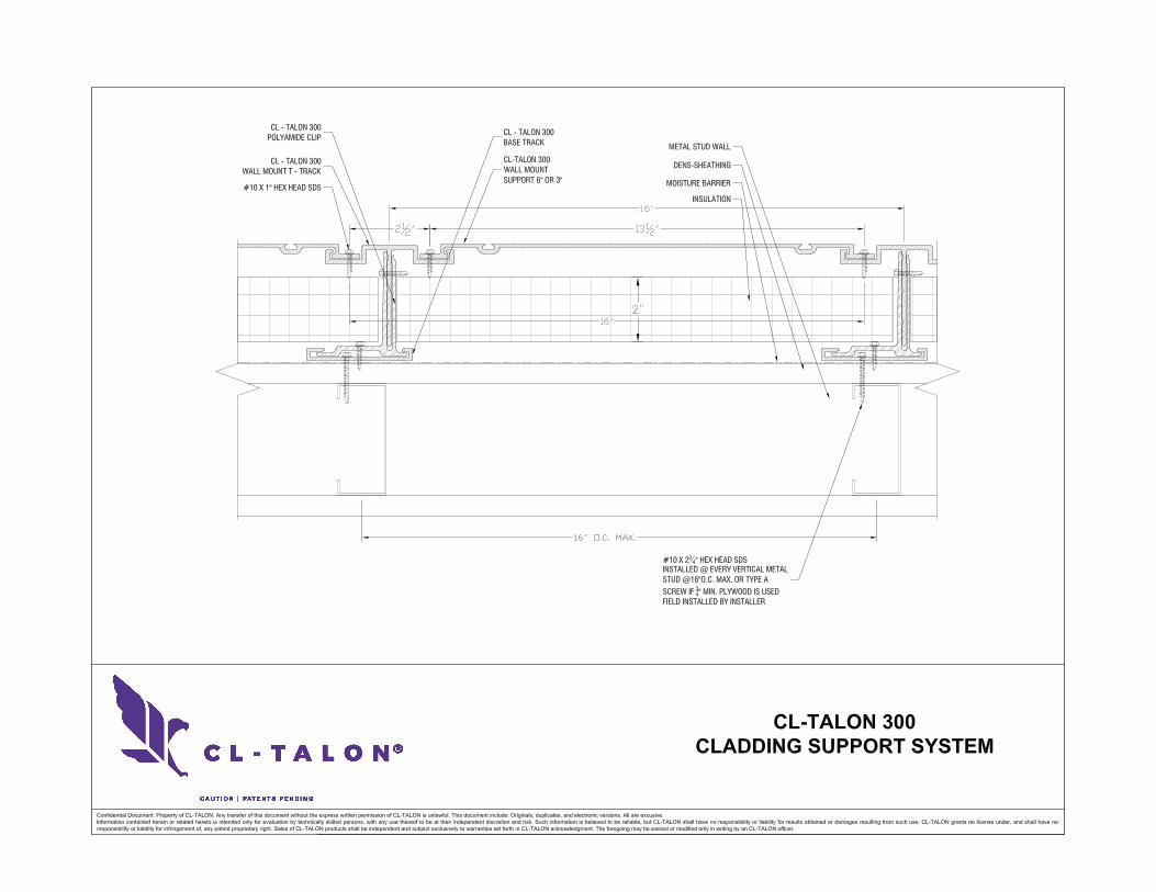
The CL-Talon 300 System in a cladding attachment system intended to support cladding and exterior insulation on a variety of substrates. The CL-Talon 300 consists of an aluminum base track fastened to the substrate. An intermittent polyamide clip is fastened to the base track and supports a continuous aluminum T-Track which in turn supports the cladding. Aluminum horizontal wall mounts are attached outboard to the T-Track for additional cladding support. The exterior insulation is fit between the clips, inboard of the face of the T-Track and horizontal mounts. Different thicknesses of insulation are accommodated by adjusting the position of the T-Track relative to the polyamide clip. The CL-Talon 300 Cladding Support System is shown below in Figure 1.1.
Figure1.1: CL-Talon 300 Cladding Support System fastened to a sheathed steel stud wall
(cladding hidden)
- 2 -
Thermal Analysis of CL-TALON Cladding Support System MH ref: 180181400
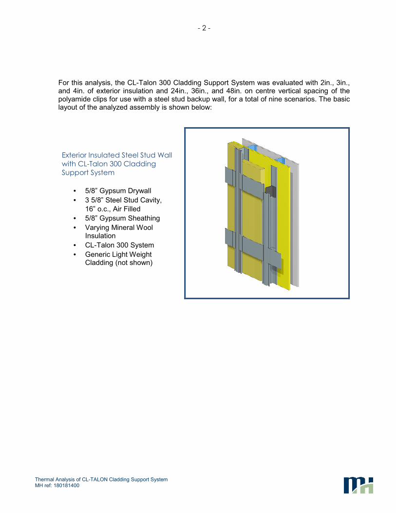
For this analysis, the CL-Talon 300 Cladding Support System was evaluated with 2in., 3in., and 4in. of exterior insulation and 24in., 36in., and 48in. on centre vertical spacing of the polyamide clips for use with a steel stud backup wall, for a total of nine scenarios. The basic layout of the analyzed assembly is shown below:
Exterior Insulated Steel Stud Wall
with CL-Talon 300 Cladding
Support System
• 5/8” Gypsum Drywall
• 3 5/8” Steel Stud Cavity,
16” o.c., Air Filled
• 5/8” Gypsum Sheathing
• Varying Mineral Wool Insulation
• CL-Talon 300 System
• Generic Light Weight Cladding (not shown)

- 3 -
Thermal Analysis of CL-TALON Cladding Support System MH ref: 180181400
2. MODELLING PROCEDURES
The thermal performance of the CL-Talon 300 Cladding Support System configurations were evaluated by 3D thermal modelling using the Nx software package from Siemens, which is a general purpose computer aided design (CAD) and finite element analysis (FEA) package. The thermal solver and modelling procedures utilized for this study were extensively calibrated and validated to within +/- 5% of hotbox testing for ASHRAE Research Project 1365-RP Thermal Performance of Building Envelope Details for Mid- and High-Rise Construction and for the Building Envelope Thermal Bridging Guide1.
The thermal analysis utilized steady-state conditions, published thermal properties of materials and information provided by CL-TALON. Additional modelling assumptions for the thermal analysis is summarized in Appendix A.
1 https://www.bchydro.com/thermalguide

- 4 -
Thermal Analysis of CL-TALON Cladding Support System MH ref: 180181400
3. THERMAL RESULTS – STEEL STUD BACKUP WALL
The following sections present the thermal performance results (U-values and effective R-values that include thermal bridging) the evaluated steel stud scenarios described in Section 1. The thermal performance of all configurations of the CL-Talon 300 Cladding Support System were evaluated at 16” o.c. horizontal spacing aligning with the steel studs in the backup wall. The polyamide clips were evaluated at varying vertical spacing of 24” o.c., 36” o.c., and 48” o.c. Three exterior insulation depths were evaluated: 2”, 3”, and 4”, with the T-Track positioning adjusted as per CL-TALON documentation. The variation in configuration of the T-Track to accommodate varying insulation thickness is shown below in Figure 3.1.
Figure 3.1: Component Arrangement for Varying Insulation Thicknesses
Table 3.1 provides the spacing of the polyamide clips, exterior insulation thickness, nominal R-value of the insulation and the determined assembly U- and effective R-Value that includes the impact of thermal bridging by the components, including studs and cladding attachments. Further assembly information, including dimensions and materials are given in Appendix B. Example temperature profiles for each configuration are provided in Appendix C.
Table 3.1: Clear Field Thermal Transmittance for CL-Talon 300 System with Steel Stud Backup
Clip
Vertical
Spacing
in
Exterior
Insulation
Thickness
in
Exterior Insulation
Nominal R-Value2
h·ft2·°F/Btu
(m2·°K/W)
Effective U-Value
Btu/h·ft2·°F
(W/m2·°K)
Effective R-Value
h·ft2·°F/Btu
(m2·°K/W)
24
2 R-8.4 (1.48) 0.110 (0.622) R-9.1 (1.61)
3 R-12.6 (2.22) 0.073 (0.416) R-13.7 (2.41)
4 R-16.8 (2.96) 0.057 (0.323) R-17.6 (3.09)
36
2 R-8.4 (1.48) 0.108 (0.612) R-9.3 (1.63)
3 R-12.6 (2.22) 0.070 (0.397) R-14.3 (2.52)
4 R-16.8 (2.96) 0.056 (0.317) R-17.9 (3.15)
48
2 R-8.4 (1.48) 0.107 (0.606) R-9.4 (1.65)
3 R-12.6 (2.22) 0.069 (0.393) R-14.4 (2.54)
4 R-16.8 (2.96) 0.054 (0.307) R-18.5 (3.26)
2 Note this value is the nominal R-value of the exterior insulation ONLY. Additional components, such as the sheathing, airspaces, and air films also all contribute an additional R-3.5 towards the nominal R-value of the entire assembly.
2" [5
0.8]
3" [7
6.2]
4" [1
01.6
]
4.5"
[114
.3]
3.5"
[88.
9]
2.5"
[63.
5]

- 5 -
Thermal Analysis of CL-TALON Cladding Support System MH ref: 180181400
4. ENERGY CODE COMPLIANCE
In the United States, the vast majority of states have an adopted energy code that set out the minimum requirements for energy efficiency for that jurisdiction, including requirements for the building envelope. The two most commonly referenced energy standards used as the basis for commercial and mid- to high-rise construction in these energy codes are ASHRAE 90.13 or IECC4, depending on the building type. Similarly in Canada, many provincial energy codes use ASHRAE 90.1 or NECB5 as the referenced energy standards. These standards may differ in specific values and requirements/exemptions, however they generally employ three main options for compliance: Prescriptive, Trade-off and Performance Paths.
The prescriptive path awards compliance for explicitly meeting all provisions of the code relevant to the project in question. For the building envelope, assemblies must be lower than a given maximum thermal transmittance U-value or must meet or exceed insulation values for a prescribed assembly. These requirements are based on climate region, construction type and occupancy type. The prescriptive path is fairly straightforward and building components need only be assessed individually. However, some of the prescriptive requirements may be difficult to achieve due to design trends. For example, in ASHRAE 90.1-2007, the prescriptive path requires a glazing to wall ratio of less than 40%. If these prescriptive requirements cannot be met, then another compliance path must be used.
The trade-off path allows for projects to trade-off the performance of building envelope components (i.e. roofs, walls, and windows) when the prescriptive requirements are not met for each and every assembly. This approach allows for flexibility in compliance if the performance of some envelope assemblies may be lower than the prescriptive values, as long as other better performing assemblies can make up for it based on area weighting of performance. For example, a low thermally performing wall may be compensated by a large roof that is above its prescriptive value. This approach can be demonstrated using either specific calculations (provided in the standards) or through computer software that is typically provided by the authors of the standard.
The performance path requires an evaluation of the annual energy use of the whole building that includes the interaction the building envelope, mechanical and electrical systems. This must be done using computer simulation, where the proposed building and its systems are modelled and compared to a compliance building. The compliance building contains the same shape, size, occupancy and scheduling of proposed building, but all of its individual components meet the minimum requirements of the standard. For example, the thermal performance of the walls of the compliance building must match the prescriptive U-values of the standard. The proposed design is acceptable if the annual energy use is less than or equal to that of the compliance building. The performance paths allows the greatest flexibility of all the compliance paths but requires a much more detailed accounting of the design. The performance path takes into account other variables such as building orientation, higher efficiency HVAC systems, and lighting controls, which would not give any benefit with the other two compliance paths. Each standard gives requirements that specify what can and cannot be included with the energy model and which energy modelling programs can be used.
3 ASHRAE 90.1 “Energy Standard for Buildings Except Low-Rise Residential Buildings” 4 IECC “International Energy Conservation Code” 5 NECB “National Energy Code for Buildings”

- 6 -
Thermal Analysis of CL-TALON Cladding Support System MH ref: 180181400
Each standard outlines their own prescriptive values for the envelope. While a jurisdiction may adopt an energy standard, each state, province or even city may modify the standard and its prescriptive values to meet their own specific energy goals. Beyond that, these standards are also updated periodically. For instance, ASHRAE 90.1 is typically updated every 3 years whereby currently versions 2007, 2010, 2013 and 2016 are used in various locations across North America. The prescriptive values in these standards typically become more stringent with each update. A local energy code may not always adopt the latest version, leading to variability of requirements across North America. With that in mind, it is always recommended for designers to be aware of the specific requirements set by the local authorities having jurisdiction for their particular project. Please see the following website from the U.S. Department of Energy for the most current energy code adoptions in the US at the state level:
https://www.energycodes.gov/status-state-energy-code-adoption
The U-values found in this report for the CL-Talon 300 system can be used to determine energy code compliance using any of the three compliance paths listed previously. For quick reference, the prescriptive U-value requirements for ASHRAE 90.1-2010, 2013 and 2016 has been reproduced in Appendix D of this report, along with comparisons to the CL-Talon 300 System with an empty steel stud backup wall. The maximum climate zone achievable prescriptively using the CL-Talon 300 system for the analyzed insulation thickness and spacing has been provided for each of those ASHRAE 90.1 versions.
- 7 -
Thermal Analysis of CL-TALON Cladding Support System MH ref: 180181400
5. CONCLUSIONSThis report summarizes the evaluation of thermal performance (U-value and effective R-values) for the CL-Talon 300 Cladding Support System with an empty steel stud backup wall with varying exterior insulation thicknesses (2”, 3” and 4” of mineral wool insulation) and CL-Talon polyamide clip spacings (24”, 36” and 48”). The following conclusions for the analyzed system scenarios can be made:
For the exterior insulated steel stud scenarios with 2”-4” of mineral wool insulation, the assembly U-values range from 0.054 BTU/hr·ft2·oF – 0.110 BTU/hr·ft2·oF (0.307 W/m2K – 0.622 W/m2K)
The clip spacing from 24” o.c. vertically to 48”o.c. vertically can improve the thermal performance by upto 5% for the scenarios analyzed.
The effectiveness of the overall assembly (thermal transmittance of assembly with thermal bridging vs thermal transmittance of the assembly with no thermal bridging) ranges from 77-91% effective depending on insulation thickness and component spacing (low end 77% for the 2” mineral wool system with 24”o.c. spacing of the polyamide clips to high end 91% for the 4” mineral wool system with 48”o.c. spacing of the polyamide clips)
The U-values shown here can be used in compliance calculations through any of the compliance paths set forth in additional energy codes and standards such as ASHRAE 90.1, IECC, and/or NECB as of the published date of this report. If there are any questions regarding the content or modelling conducted for this report, please contact the undersigned.
Morrison Hershfield Limited

- A1 -
Thermal Analysis of CL-TALON Cladding Support System
MH ref: 180181400
APPENDIX A –
MODELLING PARAMETERS AND ASSUMPTIONS
- A2 -
Thermal Analysis of CL-TALON Cladding Support System MH ref: 180181400
A.1 General Thermal Modelling Approach
For this report, a steady-state conduction model was used. The following parameters were also assumed:
Air cavity conductivities were taken from ISO 10077 and Table 3, p. 26.13 of 2013 ASHRAE Handbook – Fundamentals
Interior/exterior air films were taken from Table 1, p. 26.1 of 2009 ASHRAE Handbook – Fundamentals depending on surface orientation. The exterior air films were based on an exterior windspeed of 15mph.
Cladding materials and secondary structures outboard of the insulation can vary widely. It has been found in ASHRAE 1365, for rainscreen cavity systems most lightweight claddings have an insignificant impact on the thermal performance other than shielding the insulation from direct wind exposure. To provide general information for the system, the cladding, secondary structure outboard of the vertical rails and rainscreen cavity were not explicitly modelled, but was incorporated into the exterior film coefficient.
Material properties were taken from information provided by CL-TALON, published material information from Lawrence Berkeley National Laboratory and ASHRAE Handbook – Fundamentals for common materials. These values are typically reported at operating temperatures between 0oC and 21oC Materials used in this analysis were assumed to have a constant thermal conductivity.
From the calibration in 1365-RP, contact resistances between materials were modeled and varied between R-0.01 and R-0.2 depending on the materials and interfaces.
Insulation and other components were considered tight to adjacent interfaces. Air gaps smaller than 2mm were assumed incorporated with the contact resistances.
Placement of weather barriers and membranes were assumed not to impact the thermal conduction through the system and were not included in the analysis.
Impacts of air leakage within the assembly were not included.
The temperature difference between interior and exterior was modeled as a dimensionless temperature index between 0 and 1 (see Appendix A.3).
As per standard U-value evaluation, no solar heating impacts were included.
- A3 -
Thermal Analysis of CL-TALON Cladding Support System MH ref: 180181400
A.2 Thermal Transmittance
The methodology presented in the Building Envelope Thermal Bridging Guide separates the thermal performance of clear field assemblies and transition details (slabs, parapets, window interfaces) in order to simplify heat loss calculations.
For this report, only clear field transmittances for this system were evaluated, and not any transition details. The presented U-values in the Tables in this report contain only uniform repeating thermal bridges, such as studs and clips, and do not include any interface details, such as slab intersections or top and bottom stud tracks.
A.3 Temperature Index
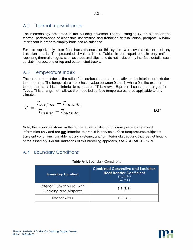
The temperature index is the ratio of the surface temperature relative to the interior and exterior temperatures. The temperature index has a value between 0 and 1, where 0 is the exterior temperature and 1 is the interior temperature. If Ti is known, Equation 1 can be rearranged for Tsurface. This arrangement allows the modelled surface temperatures to be applicable to any climate.
�� =������ − ��� ���
������ − ��� ���
EQ 1
Note, these indices shown in the temperature profiles for this analysis are for general
information only and are not intended to predict in-service surface temperatures subject to
transient conditions, variable heating systems, and/ or interior obstructions that restrict heating
of the assembly. For full limitations of this modeling approach, see ASHRAE 1365-RP
A.4 Boundary Conditions
Table A-1: Boundary Conditions
Boundary Location
Combined Convective and Radiation
Heat Transfer Coefficient BTU/hft2oF
(W/m2K)
Exterior (15mph wind) with
Cladding and Airspace 1.5 (8.3)
Interior Walls 1.5 (8.3)

- B1 -
Thermal Analysis of CL-TALON Cladding Support System MH ref: 180181400
APPENDIX B –
ASSEMBLY INFORMATION AND MATERIAL PROPERTIES
- B2 -
Thermal Analysis of CL-TALON Cladding Support System MH ref: 180181400
B.1 CL-Talon 300 Cladding Support System with Steel Stud Backup
Wall
8
9
7
6
54
32
1
- B3 -
Thermal Analysis of CL-TALON Cladding Support System MH ref: 180181400
Ref. Component Thickness
Inches
(mm)
Conductivity Btu·in / ft2·hr·oF
(W/m K)
Nominal Resistance hr· ft2· oF/BTU
(m2K/W)
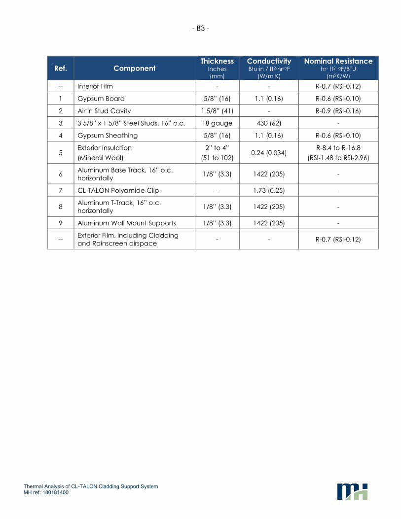
-- Interior Film - - R-0.7 (RSI-0.12)
1 Gypsum Board 5/8” (16) 1.1 (0.16) R-0.6 (RSI-0.10)
2 Air in Stud Cavity 1 5/8” (41) - R-0.9 (RSI-0.16)
3 3 5/8” x 1 5/8” Steel Studs, 16” o.c. 18 gauge 430 (62) -
4 Gypsum Sheathing 5/8” (16) 1.1 (0.16) R-0.6 (RSI-0.10)
5 Exterior Insulation
(Mineral Wool)
2” to 4”
(51 to 102) 0.24 (0.034)
R-8.4 to R-16.8
(RSI-1.48 to RSI-2.96)
6 Aluminum Base Track, 16” o.c.
horizontally 1/8” (3.3) 1422 (205) -
7 CL-TALON Polyamide Clip - 1.73 (0.25) -
8 Aluminum T-Track, 16” o.c.
horizontally 1/8” (3.3) 1422 (205) -
9 Aluminum Wall Mount Supports 1/8” (3.3) 1422 (205) -
-- Exterior Film, including Cladding
and Rainscreen airspace - - R-0.7 (RSI-0.12)

- C1 -
Thermal Analysis of CL-TALON Cladding Support System
MH ref: 180181400
APPENDIX C –
SIMULATED TEMPERATURE PROFILES

- C1 -
Thermal Analysis of CL-TALON Cladding Support System MH ref: 180181400
C.1 CL-Talon 300 with Steel Stud Backup Wall
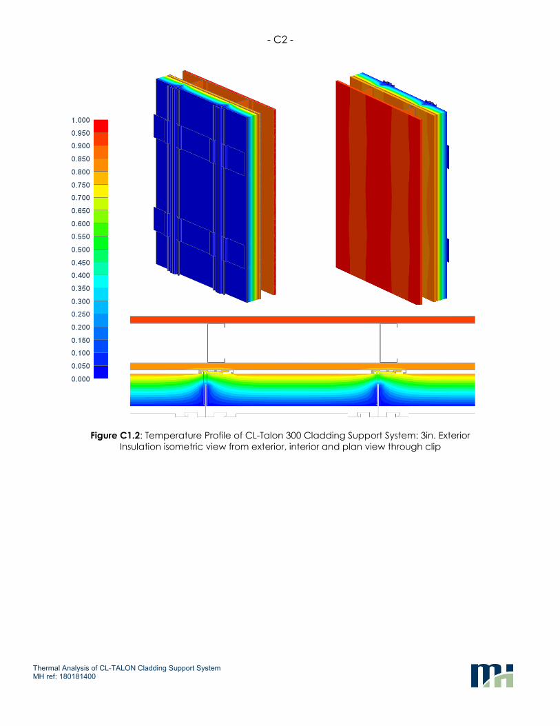
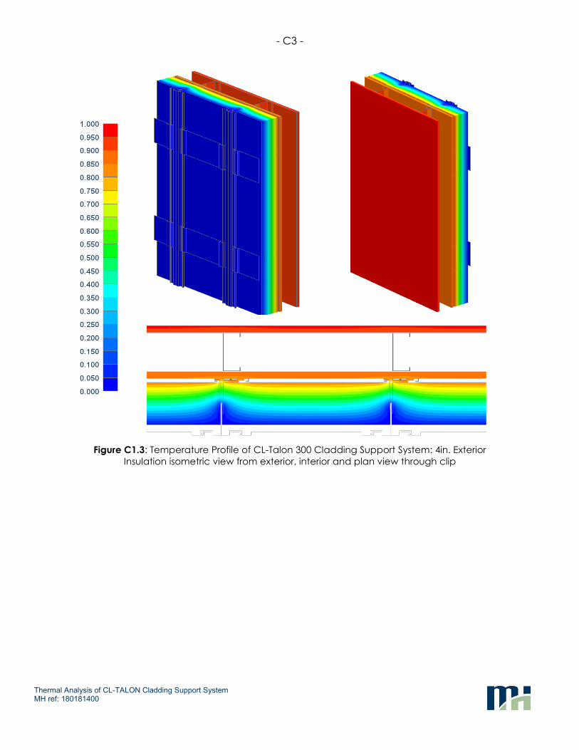
As an example of the thermal profiles of the CL-Talon 300 system, the following figures illustrate typical temperature distribution for the CL-Talon 300 system with 2in., 3in., and 4in. exterior insulation at 24in. o.c. vertical clip spacing. The profiles presented as a temperature index (between 0 and 1). See Appendix A.3 for more information.
Figure C1.1: Temperature Profile of CL-Talon 300 Cladding Support System: 2in. Exterior
Insulation isometric view from exterior, interior and plan view through clip
- C2 -
Thermal Analysis of CL-TALON Cladding Support System MH ref: 180181400
Figure C1.2: Temperature Profile of CL-Talon 300 Cladding Support System: 3in. Exterior
Insulation isometric view from exterior, interior and plan view through clip
- C3 -
Thermal Analysis of CL-TALON Cladding Support System MH ref: 180181400
Figure C1.3: Temperature Profile of CL-Talon 300 Cladding Support System: 4in. Exterior
Insulation isometric view from exterior, interior and plan view through clip
- D1 -
APPENDIX D –
ASHRAE 90.1 PRESCRIPTIVE PATH COMPARISON
- D2 -
Thermal Analysis of CL-TALON Cladding Support System MH ref: 180181400
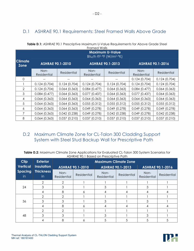
D.1 ASHRAE 90.1 Requirements: Steel Framed Walls Above Grade
Table D.1: ASHRAE 90.1 Prescriptive Maximum U-Value Requirements for Above Grade Steel
Framed Walls
Climate
Zone
Maximum U-Value
Btu/h·ft2·°F (W/m2·°K)
ASHRAE 90.1-2010 ASHRAE 90.1-2013 ASHRAE 90.1-2016
Non-
Residential Residential
Non-
Residential Residential
Non-
Residential Residential
0 -- -- -- -- 0.124 (0.704) 0.124 (0.704)
1 0.124 (0.704) 0.124 (0.704) 0.124 (0.704) 0.124 (0.704) 0.124 (0.704) 0.124 (0.704)
2 0.124 (0.704) 0.064 (0.363) 0.084 (0.477) 0.064 (0.363) 0.084 (0.477) 0.064 (0.363)
3 0.084 (0.477) 0.064 (0.363) 0.077 (0.437) 0.064 (0.363) 0.077 (0.437) 0.064 (0.363)
4 0.064 (0.363) 0.064 (0.363) 0.064 (0.363) 0.064 (0.363) 0.064 (0.363) 0.064 (0.363)
5 0.064 (0.363) 0.064 (0.363) 0.055 (0.312) 0.055 (0.312) 0.055 (0.312) 0.055 (0.312)
6 0.064 (0.363) 0.064 (0.363) 0.049 (0.278) 0.049 (0.278) 0.049 (0.278) 0.049 (0.278)
7 0.064 (0.363) 0.042 (0.238) 0.049 (0.278) 0.042 (0.238) 0.049 (0.278) 0.042 (0.238)
8 0.064 (0.363) 0.037 (0.210) 0.037 (0.210) 0.037 (0.210) 0.037 (0.210) 0.037 (0.210)
D.2 Maximum Climate Zone for CL-Talon 300 Cladding Support
System with Steel Stud Backup Wall for Prescriptive Path
Table D.2: Maximum Climate Zone Applications for Evaluated CL-Talon 300 System Scenarios for
ASHRAE 90.1 Based on Prescriptive Path
Clip
Vertical
Spacing
in
Exterior
Insulation
Thickness
in
Maximum Climate Zone
ASHRAE 90.1-2010 ASHRAE 90.1-2013 ASHRAE 90.1-2016
Non-
Residential Residential
Non-
Residential Residential
Non-
Residential Residential
24
2 2 1 1 1 1 1
3 3 1 3 1 3 1
4 8 6 4 4 4 4
36
2 2 1 1 1 1 1
3 3 1 3 1 3 1
4 8 6 4 4 4 4
48
2 2 1 1 1 1 1
3 3 1 3 1 3 1
4 8 6 5 5 5 5