thermal diffusion boron doping of single-crystal natural ... by...thermal diffusion boron doping of...
TRANSCRIPT

Thermal diffusion boron doping of single-crystal natural diamondJung-Hun Seo, Henry Wu, Solomon Mikael, Hongyi Mi, James P. Blanchard, Giri Venkataramanan, WeidongZhou, Shaoqin Gong, Dane Morgan, and Zhenqiang Ma Citation: Journal of Applied Physics 119, 205703 (2016); doi: 10.1063/1.4949327 View online: http://dx.doi.org/10.1063/1.4949327 View Table of Contents: http://scitation.aip.org/content/aip/journal/jap/119/20?ver=pdfcov Published by the AIP Publishing Articles you may be interested in Electroluminescence and capacitance-voltage characteristics of single-crystal n-type AlN (0001)/p-type diamond(111) heterojunction diodes Appl. Phys. Lett. 98, 011908 (2011); 10.1063/1.3533380 Growth of thick heavily boron-doped diamond single crystals: Effect of microwave power density Appl. Phys. Lett. 97, 182101 (2010); 10.1063/1.3511449 Effect of fluorine implantation dose on boron thermal diffusion in silicon J. Appl. Phys. 96, 4114 (2004); 10.1063/1.1790063 High-quality heterojunction between p-type diamond single-crystal film and n-type cubic boron nitride bulk singlecrystal Appl. Phys. Lett. 83, 4854 (2003); 10.1063/1.1631059 P -type polycrystalline diamond layers by rapid thermal diffusion of boron Appl. Phys. Lett. 76, 849 (2000); 10.1063/1.125605
Reuse of AIP Publishing content is subject to the terms at: https://publishing.aip.org/authors/rights-and-permissions. Download to IP: 128.104.183.36 On: Tue, 24 May 2016
15:13:35

Thermal diffusion boron doping of single-crystal natural diamond
Jung-Hun Seo,1 Henry Wu,2 Solomon Mikael,1 Hongyi Mi,1 James P. Blanchard,3
Giri Venkataramanan,1 Weidong Zhou,4 Shaoqin Gong,5 Dane Morgan,2
and Zhenqiang Ma1,a)
1Department of Electrical and Computer Engineering, University of Wisconsin-Madison, Madison,Wisconsin 53706, USA2Department of Materials Science and Engineering, University of Wisconsin-Madison, Madison,Wisconsin 53706, USA3Department of Nuclear Engineering and Engineering Physics, University of Wisconsin-Madison, Madison,Wisconsin 53706, USA4Department of Electrical Engineering, NanoFAB Center, University of Texas at Arlington, Arlington,Texas 76019, USA5Department of Biomedical Engineering and Wisconsin Institute for Discovery,University of Wisconsin-Madison, Madison, Wisconsin 53706, USA
(Received 30 March 2016; accepted 29 April 2016; published online 24 May 2016)
With the best overall electronic and thermal properties, single crystal diamond (SCD) is the extreme
wide bandgap material that is expected to revolutionize power electronics and radio-frequency elec-
tronics in the future. However, turning SCD into useful semiconductors requires overcoming doping
challenges, as conventional substitutional doping techniques, such as thermal diffusion and ion implan-
tation, are not easily applicable to SCD. Here we report a simple and easily accessible doping strategy
demonstrating that electrically activated, substitutional doping in SCD without inducing graphitization
transition or lattice damage can be readily realized with thermal diffusion at relatively low tempera-
tures by using heavily doped Si nanomembranes as a unique dopant carrying medium. Atomistic simu-
lations elucidate a vacancy exchange boron doping mechanism that occurs at the bonded interface
between Si and diamond. We further demonstrate selectively doped high voltage diodes and half-
wave rectifier circuits using such doped SCD. Our new doping strategy has established a reachable
path toward using SCDs for future high voltage power conversion systems and for other novel dia-
mond based electronic devices. The novel doping mechanism may find its critical use in other wide
bandgap semiconductors. Published by AIP Publishing. [http://dx.doi.org/10.1063/1.4949327]
I. INTRODUCTION
With the advent of various new renewable energy sources
and the emerging need to deliver and convert energy more
efficiently, power electronics have received unprecedented
attention in recent years. For the last several decades, Si-
based power devices have played a dominant role in power
conversion electronics. Wide bandgap semiconductor material
based power electronics, such as those employing GaN and
SiC, are expected to handle more power with higher efficiency
than Si-based ones. GaN exhibits higher saturation velocity
than Si. However, the thermal conductivity of GaN is low for
power conversion systems. Moreover, it is currently difficult to
obtain a thick and high quality GaN layer. SiC has its own
native substrate, but it has inferior performance matrices (e.g.,
Johnson’s figure of merit) versus GaN. In comparison, diamond
exhibits most of the critical material properties for power elec-
tronics, except for its small substrate size at present. Diamond
has a wide bandgap, high critical electric field, high carrier mo-
bility, high carrier saturation velocities, and the highest thermal
conductivity among all available semiconductor materials.1–3
Due to its superior electrical properties, the thickness of the
highest quality diamond required to block an equivalent
amount of voltage is approximately one-fifth to one-fourth the
thicknesses of GaN or SiC. In particular, the superior thermal
conductivity of diamond could greatly simplify the design of
heat dissipation and hence simplify entire power electronics
modules. Therefore, diamond is considered the best material
candidate for power electronics in terms of power switching ef-
ficiency, reliability, and system volume and weight. However,
besides the lack of large area single crystalline diamond (SCD)
substrate, SCD is ultra-stable and chemically inert to most reac-
tive reagents, due to the strong r-bonds formed between adja-
cent carbon atoms, making substitutional doping very
difficult.4 Because of the doping difficulty, the majority of
diamond-based diodes reported to date are Schottky diodes.5–8
Ion implantation has been attempted to achieve substitu-
tional doping of SCD.9,10 However, the ion implantation
process needs to be carried out at elevated temperatures
(400–600 �C) to prevent bulk phase transition-graphitiza-
tion.11–13 In addition, a very high annealing temperature
(1450 �C) under a high vacuum (�10�6 mTorr) is required to
potentially restore damaged lattices and to activate implanted
dopants. During this annealing process and for high dose im-
plantation in particular, surface graphitization still occurs,
thereby creating additional unwanted processing complica-
tions for practical applications.9–11 The alternative approach
to ion implantation is in-situ doping during the epitaxial
growth of diamond.2,3,14,15 However, this in-situ doping
method has a number of intrinsic limitations for practical use
a)Author to whom correspondence should be addressed. Electronic mail:
0021-8979/2016/119(20)/205703/8/$30.00 Published by AIP Publishing.119, 205703-1
JOURNAL OF APPLIED PHYSICS 119, 205703 (2016)
Reuse of AIP Publishing content is subject to the terms at: https://publishing.aip.org/authors/rights-and-permissions. Download to IP: 128.104.183.36 On: Tue, 24 May 2016
15:13:35

(e.g., selective doping) due to the need for high temperature
and for high density plasma during growth. For example, real-
izing uniform doping concentrations across a single diamond
substrate using plasma enhanced epitaxial growth is rather
challenging due to high plasma concentrations near the edges
of diamond substrates. The small size of diamond as a sub-
strate worsens the non-uniformity doping problem of in-situdoping. Using in-situ doping also further affects film growth
uniformity and crystal quality during plasma assisted epitaxial
growth. These issues make selective doping of diamond film
nearly impossible, and yet selective and uniform doping is
very attractive and necessary for most device applications.
Previously, a solid boron film was deposited on polycrystal-
line diamond in order to allow boron thermal diffusion dop-
ing.7 While a very high temperature (1600 �C) is needed in
this process and the feasibility of this method in the context of
SCD doping is unknown, diodes made of polycrystalline dia-
mond always show very high leakage current.
Here we demonstrate a very simple, yet viable method
for selective boron doping in natural SCD (nSCD) via an easy
thermal diffusion process at a much lower temperature than
those used in any other doping methods. We use heavily
doped silicon nanomembranes (SiNMs), which are now easily
accessible, as our dopant carrying medium. Standalone SiNM,
since its first appearance in 2005, has been extensively inves-
tigated.16 The processing of SiNM, including transferring,
doping, and bonding, can be readily carried out with conven-
tional processing tools. The SiNM is typically released in thin
single-crystal silicon sheets, e.g., from a silicon-on-insulator
(SOI) wafer, with thicknesses ranging from a few nanometers
up to microns. The thinness of SiNM brings in a number of
electronic and mechanical properties that are not possessed by
its rigid counterparts (i.e., bulk Si). These unique properties
have been extensively harnessed in recent years. A summary
of the detailed processing methods of nanomembranes,
including their creation, manipulation, etc., and their signifi-
cant applications can be found elsewhere.16–18
In this work, we first exploit the bonding advantages of
SiNMs. In comparison with a regular/bulk Si substrate that is
rigid and rather difficult to bond to diamond, the bonding
force of SiNMs is much stronger than rigid Si due to its thin
thickness. As described earlier,16 the bonding force increases
exponentially with the reduction of Si thickness, which is a
unique and important property of flexible SiNM. The ultra-
mechanical flexibility of SiNM also allows much more
conformal and higher fidelity bonding and better surface
roughness tolerance when bonding with diamond, both of
which facilitate intimate contacts between SiNM and dia-
mond (nearly 100% bonding yield without using any adhe-
sives and no limitation on SiNM’s size or shape). Also, due
to the thinness of SiNM, we are able to exploit it for dopant
carrying. SiNM, like bulk Si, can be heavily doped via con-
ventional ion implantation and post-implant thermal anneal-
ing without destroying its single crystal structure. Unlike
bulk Si, SiNM can be easily heavily doped across its full
thickness due to its thinness. A detailed description of the
method to realize SiNM full-thickness heavy doping can be
found from recent publications.17–19 Heavily boron doped
thin SiNM was bonded to diamond to serve as the dopant-
carrying medium for thermal diffusion in this work. As
detailed in the supplementary material (Fig. S1),43 the prepa-
ration and application of SiNM as a dopant carrying medium
for diamond are relatively easy and straightforward. It should
also be noted that heavily doped SOI wafer is also commer-
cially available and that the doping process described here
(in supplementary material) can be considerably simplified if
using such SOI wafer.
Besides the process simplicity, the SiNM based thermal
diffusion doping method leads to effective, uniform, and
selective heavy doping in SCD. No graphitization is induced
even on the diamond surface as long as it is covered by
SiNM. Without involving high temperature or high vacuum
furnace, the doping process can be readily realized using
conventional rapid thermal annealing (RTA) process, which
is widely accessible in comparison with ion implantation and
in-situ doping methods. In addition, the doping method
proves to be very effective in forming a shallowly doped p-
type layer in diamond, which is sufficient for most device
applications, while keeping its single crystallinity intact. It is
noted that realizing very shallow doping in many semicon-
ductors, such as Si, has been very challenging until the recent
successful demonstration by Hoarfrost et al.42
II. EXPERIMENT
Fig. 1(a) illustrates the boron doping process flow. The
(220) oriented type IIa natural diamond plate used in this
experiment was purchased from Fraunhofer-Institut f€ur
Angewandte Festk€orperphysik (IAF). The process detail can
be found in the supplementary material.43 In brief, heavily
boron-doped single crystal SiNMs are first formed on an SOI
substrate and then released by selective etching-away of bur-
ied oxide. The released SiNMs are transferred to diamond
substrate via the stamp-assisted transfer printing method.20
The diamond plate bearing the SiNMs is annealed via RTA to
first form a stronger bonding and then to induce boron diffu-
sion from Si into diamond. The doping mechanism is
described later in the text.
The thermal diffusion doping method has a comparative
advantage over ion implantation in that lattice structural
damages are not introduced during thermal diffusion.
Therefore, the high temperature recrystallization process
needed for post ion implantation is no longer necessary and
graphitization can be readily avoided. It is also expected that
higher crystal quality can be obtained using the thermal dif-
fusion method as opposed to the ion implantation method af-
ter finishing the doping process. By using the transfer
printing method, clean interfaces are ensured and impor-
tantly, selective doping (to be seen later), via deterministic
transfer printing of SiNMs of different sizes to the selective
areas on the diamond surface, is made easy and precise.21
The selective doping enabled by selective transfer printing,
while applicable to any size and shape of diamond plates (in
contrast to direct wafer bonding), leads to a planar doped
structure that can facilitate device implementations. Figs.
1(b) and 1(c) show images of natural diamond before and af-
ter SiNM bonding.
205703-2 Seo et al. J. Appl. Phys. 119, 205703 (2016)
Reuse of AIP Publishing content is subject to the terms at: https://publishing.aip.org/authors/rights-and-permissions. Download to IP: 128.104.183.36 On: Tue, 24 May 2016
15:13:35
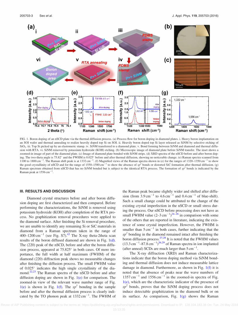
III. RESULTS AND DISCUSSION
Diamond crystal structures before and after boron diffu-
sion doping are first characterized and then compared. Before
performing the characterizations, the SiNM is removed using
potassium hydroxide (KOH) after completion of the RTA pro-
cess. No graphitization removal procedures were applied to
the diamond surface. After finishing the Si removal procedure,
we are unable to identify any remaining Si or SiC materials in
diamond from a Raman spectrum taken in the range of
400–1200 cm�1 (see Fig. S7).43 The X-ray theta-2theta scan
results of the boron diffused diamond are shown in Fig. 1(d).
The (220) peak of the nSCD, before and after the boron diffu-
sion process, appeared at 75.825� in both cases. Of more im-
portance, the full width at half maximum (FWHM) of the
diamond (220) diffraction peak shows no measurable changes
after finishing the diffusion process. The small FWHM value
of 0.025� indicates the high single crystallinity of the dia-
mond.22,23 The Raman spectra of the nSCD before and after
diffusion doping are shown in Fig. 1(e) for comparison. The
zoomed-in view of the relevant wave number range of Fig.
1(e) is shown in Fig. 1(f). The sp3 bonding in the sample
before and after the thermal diffusion process is clearly indi-
cated by the TO phonon peak at 1332 cm�1. The FWHM of
the Raman peak became slightly wider and shifted after diffu-
sion (from 3.9 cm�1 to 4.6 cm�1 and 0.4 cm�1 of blue-shift).
Such a small change could be attributed to the change of the
existing crystal imperfection in the nSCD or small stress dur-
ing the process. Our nSCD before processing does not have as
small FWHM value (2–3 cm�1)24–26 in comparison with some
of the others that are reported in literature, indicating the exis-
tence of some crystal imperfection. However, the FWHM is
smaller than 5 cm�1 in both cases, further indicating that the
sp3 bonding in the diamond remained intact after finishing the
boron diffusion process.27,28 It is noted that the FWHM values
(13.3 cm�1–87.8 cm�1)26,29 of Raman spectra in ion implanted
(after anneal) SCDs are much larger than 5 cm�1.
The X-ray diffraction (XRD) and Raman characteriza-
tions indicate that the boron doping method via SiNM bond-
ing and thermal diffusion does not induce measurable lattice
damage in diamond. Furthermore, as shown in Fig. 1(f) it is
noted that the absence of peaks near the wave numbers of
1357 cm�1 and 1556 cm�1 in the zoomed-in spectra of Fig.
1(e), which are the characteristic indicator of the presence of
sp2 bonds, proves that the SiNM doping process does not
induce detectable graphitization in the diamond bulk or on
its surface. As comparison, Fig. 1(g) shows the Raman
FIG. 1. Boron doping of an nSCD plate via the thermal diffusion process. (a) Process flow for boron doping in diamond plates. i. Heavy boron implantation on
an SOI wafer and thermal annealing to realize heavily doped top Si on SOI. ii. Heavily boron doped top Si layer released as SiNM by selective etching of
SiO2. iii. Top Si picked up by an elastomeric stamp. iv. SiNM transferred to a diamond plate. v. Bond forming between SiNM and diamond and thermal diffu-
sion with RTA. vi. SiNM removed by potassium hydroxide (KOH) etching. (b) Microscopic image of diamond plate before SiNM transfer. The inset shows a
zoomed-in image of part of the diamond plate. (c) Image of diamond plate bonded with SiNM strips. (d) XRD spectra of the nSCD before and after boron dop-
ing. The two-theta angle is 75.82� and the FWHM is 0.025� before and after thermal diffusion, showing no noticeable change. (e) Raman spectra scanned from
1100 to 1800 cm�1. The Raman shift peak is at 1332 cm�1. (f) Magnified views of the Raman spectra shown in (e) for the ranges of 1320–1350 cm�1 to show
the good crystallinity of nSCD and for the range of 1550–1580 cm�1 to show the absence of sp2 bonds or distorted SiC formation after thermal diffusion. (g)
Raman spectrum obtained from nSCD that has no SiNM bonded but is subject to the identical RTA process. The formation of sp2 bonds is indicated by the
Raman peak at 1556 cm�1.
205703-3 Seo et al. J. Appl. Phys. 119, 205703 (2016)
Reuse of AIP Publishing content is subject to the terms at: https://publishing.aip.org/authors/rights-and-permissions. Download to IP: 128.104.183.36 On: Tue, 24 May 2016
15:13:35

spectrum scanned from a reference nSCD sample that has no
SiNM bonded but was subject to the identical RTA process.
The distinct Raman peak at the wave number of 1556 cm�1
in the spectrum clearly indicates the existence of sp2 bonds
that are formed on this undoped sample. To further verify
the role of SiNM in preventing graphitization on the dia-
mond surface, the Raman spectrum taken from the backside
of the SiNM bonded diamond (associated with Fig. 1(e) and
1(f)), where no SiNM is bonded, also shows a visible peak at
the wave number of 1556 cm�1 (see Fig. S3). These results
indicate that it is because of using single crystal SiNM as the
dopant carrying medium for thermal diffusion that we have
successfully avoided graphitization on the diamond surface.
The diffused boron atom concentration in the nSCD is
characterized by both secondary ion mass spectroscopy
(SIMS) and capacitance-voltage (C�V) measurements. The
results are shown in Fig. 2(a) and the fitted curves by the
Fick’s law of diffusion are shown in Fig. S4. Fig. 2(a) indi-
cates the presence of boron at a concentration of about
1� 1019 cm�3 at the diamond surface, which is comparable
with the level that can be achieved by ion implantation, and
gradually decreased to �2� 1015 cm�3 at a depth of
�70 nm. As a comparison, �120 cm2/v�s of hole mobility
and the doping concentration of �2� 1018 cm�3 were meas-
ured by using Hall measurements (Accent HL5500 Hall sys-
tem). Considering that the annealing time is only 40 min, the
doping depth achieved is encouraging for device applica-
tions. The profile obtained by C�V measurements roughly
matches that of SIMS in terms of shape and depth consider-
ing the limited accuracy of SIMS. The additional experiment
under various diffusion time and temperature conditions is
under investigation.
Further characterizations of boron-doped nSCD were
performed using Fourier transform infrared spectroscopy
(FTIR). Generally, boron inactivation could result from non-
substitutional boron sites30 or aggregated substitutional bo-
ron sites.31,32 FTIR is an effective method for evaluating the
substitutional doping status in a diamond. The FTIR results
are shown in Fig. 2(b). Fig. 2(b–i) shows two diamond plates
of the same type: one is boron doped (scanning region B)
that is realized using the above thermal diffusion method and
the other is undoped (scanning region C) as a reference.
Figs. 2(b-ii)–(2-iv) show the FTIR mapping results and the
scanned spectra. The boron doped diamond shows the char-
acteristic absorption peak at 1290 cm�1, which clearly indi-
cates the electrical activation of boron atoms.33 In contrast,
the peak does not appear in the undoped reference diamond.
Since substitutional doping, i.e., boron-carbon sp3 bonding
formation, is necessary for electrical activation of doped bo-
ron atoms, the FTIR and the C�V characterization results
prove the substitutional doping of boron atoms in the nSCD.
It should be noted that the characteristic absorption peaks
associated with boron interstitials and boron interstitial com-
plexes in diamond can be observed at 1420, 1530, 1570, and
1910 cm�1, but no such peaks appeared in our FTIR spec-
tra.34 Moreover, the absence of the three infrared B-B cluster
absorption peaks (553, 560, and 570 cm�1) indicate that no
aggregated substitutional boron sites were formed.35 The
broader peaks, which appear from 1900 to 2300 cm�1 are the
inherent two-phonon lines of diamond associated with C�C
bonds. They appear in both the boron doped and undoped di-
amond samples.
X-ray photoelectron spectroscopy (XPS) was performed
on both doped diamond and undoped diamond (as a refer-
ence). The binding energies for Si1s, B1s and C1s peaks have
been identified with constant pass energy of 50 eV and
100 meV energy step as shown in Fig. 2(c). The C–Si peak at
�103 eV indicates that a chemical reaction between Si and
carbon atoms has occurred at the Si–diamond interface (Fig.
2(c-i). However, the absence of an Si peak in the Raman
spectrum (Fig. S7) in the range of 400–1200 cm�1 indicates
that the C-Si reaction occurred very shallowly (<10 nm) at
the diamond surface.43 Boron substitution in diamond
yielded a B1s peak at 190.6 eV corresponding to B–C (Fig.
2(c-ii)) confirming that boron doping was successful. This is
consistent with the SIMS, C�V, and FTIR analyses. Fig.
2(c–iii) shows the XPS spectra for the core C1s peak in the
binding energy region around 280–295 eV for the undoped
and boron doped nSCD samples. De-convoluted C1s peaks
using the Gaussian/Lorentzian function in the inset of Fig.
2(c-iii) shows a strong sp3 C–C bonding at 285.4 eV and a
very small C–O and C¼O bonding at 286.4 eV and
287.9 eV, respectively, indicating that the single crystallinity
of nSCD was not degraded by the boron diffusion process.
The XPS results obtained above suggest clues for eluci-
dating the boron diffusion doping mechanisms. Especially,
the C-Si bonding (Fig. 2(c-i) plays an important role for the
observed boron diffusion. First-principles density functional
theory (DFT) simulations36,37 were performed to understand
the diffusion mechanism. Two mechanisms were proposed to
yield enhanced boron diffusion through enhanced vacancies
in diamond (detailed calculation can be found in the supple-
mentary material). The first mechanism involves injection of
excess vacancies into the diamond from the SiNM, which has
a much larger intrinsic vacancy concentration than diamond
as well as excess vacancies from ion implantation into the
SiNM. DFT calculations verify that this vacancy injection is
much more energetically favorable than the usual mechanism
for vacancy formation in diamond (movement of carbon to
the diamond surface). Fig. 2(d) shows the cartoon illustration
of the proposed injection and diffusion mechanism. Besides
the above vacancy injection into diamond from Si, excess
vacancies can also be additionally created by formation of
SiC at the SiNM and diamond interface, which stabilized the
vacancies by almost exactly the required 0.7 eV needed to
explain the enhanced boron diffusion rate into diamond. Both
mechanisms could play a role and further research is required
to elucidate their contributions. In each case, diffused boron
atoms from Si are expected to immediately become substitu-
tional atoms in diamond if the diamond does not have pre-
existing vacancy related defects (ideal situation). Since no
vacancy defects are additionally generated in diamond during
the diffusion process, a high temperature anneal that is neces-
sary for post-implantation38 then becomes unnecessary in
such a doping process.
Based on the identified vacancy exchange mechanism, it
is unlikely that boron atoms diffuse to non-substitutional sites,
which is different from ion implantation induced case.30,39 It
205703-4 Seo et al. J. Appl. Phys. 119, 205703 (2016)
Reuse of AIP Publishing content is subject to the terms at: https://publishing.aip.org/authors/rights-and-permissions. Download to IP: 128.104.183.36 On: Tue, 24 May 2016
15:13:35

is also noted that the realized boron doping concentration in
our method is much lower than that realized in synthetic dia-
mond,31,32 and therefore the likelihood of forming aggregated
boron substitutional sites should be rather small.
Substitutional boron doping in diamond using thermal
diffusion has never been considered possible in the past. Our
experiment clearly demonstrated the viability of boron doping
through the thermal diffusion process using heavily doped,
bonded SiNM as dopant carrying medium. The process is also
simple and easily accessible. We propose that the origin
of the successful doping is enhanced boron diffusion into
diamond enabled by the Si-C bonding states near the
Si–diamond interface, which lower the energy to create dia-
mond vacancies and enhance boron transport.
FIG. 2. Analysis of thermally diffused nSCD. (a) Comparison of boron doping profiles measured by SIMS and C�V methods. (b) i. Microscopic image of two
diamond samples scanned by FTIR. The regions A and D are background. The region B is boron doped nSCD and the region C is undoped reference nSCD. ii.
2D FTIR scanning image corresponding to the image shown in i. The brighter color indicates stronger absorption as shown in the color scale bar. iii.
Comparison of FTIR spectra between boron-doped nSCD and undoped nSCD. The strong absorption near the wave number of 1290 cm�1 indicates electrically
activated boron atoms; the reference sample does not have any peaks near the wave numbers of interest. iv. An individual FTIR spectrum obtained from
regions B and C for a detailed view. (c) XPS spectra of boron doped (blue) and undoped (red) nSCD for i. Si1s, ii. B1s, and iii. C1s peaks. Inset in Fig. 2(c) iii
shows zoomed-in view of the deconvoluted C1s peak. (d) Cartoon illustration of the proposed boron incorporation mechanism. i. Si–diamond interface just af-
ter SiNM bonding to nSCD, before thermal processing. Vacancies predominately occur on the Si-side, and all boron atoms are initially present on the Si-side.
ii. Vacancy from the Si-side migrates across the interface, exchanging with a carbon atom from the diamond-side. This process generates a vacancy on the
diamond-side at a smaller energy cost than the usual vacancy formation mechanism in diamond. iii. Boron atoms from the Si-side are now able to exchange
with the new vacancy on the diamond-side. iv. Finally, boron is incorporated into diamond as a substitutional solute and can undergo accelerated diffusion by
vacancies generated through steps i and ii. Please note that the schematic illustration is not meant to imply lattice matching of Si and diamond at the interface.
205703-5 Seo et al. J. Appl. Phys. 119, 205703 (2016)
Reuse of AIP Publishing content is subject to the terms at: https://publishing.aip.org/authors/rights-and-permissions. Download to IP: 128.104.183.36 On: Tue, 24 May 2016
15:13:35

The graphitization-free process is thought to be directly
related to the intimate bonding between Si and diamond. A
previous study has shown that introducing impurities at ele-
vated temperature in diamond can prohibit graphitization
during thermal annealing.13 In the current thermal diffusion
experiment, boron atoms accumulate at the bonded surface
of the diamond as soon as thermal diffusion begins to occur
at an elevated temperature. Therefore, no phase transition is
expected to happen at the SiNM bonded diamond surface
under the special thermal diffusion setting. This expectation
is consistent with experimental observations.
The above boron doping method is used to fabricate
diodes using a 2� 2 mm2, 120 lm thick nSCD plate (Fig. 3).
Fig. 3(a) shows the process flow for fabricating vertical p-ijunction diodes. After completion of SiNM bonding and bo-
ron thermal diffusion from SiNM to diamond (Fig. 1(a-v) the
cathode is formed first on the bottom side of the diamond
plate. The anode is formed directly on top of the SiNMs
(Fig. 1(a-ii)), which previously served as a boron carrying
medium, since it is much easier to form ohmic contacts on
heavily p-type doped Si. It is noted that a p-i junction is not
formed between Si and diamond in this case, but between
the p-type doped diamond surface and the intrinsic diamond
bulk. Both the anode and the cathode contacts are ohmic
contacts. To prove that the p-i junction is formed in diamond
not in between Si and diamond, a p-i diamond diode without
an SiNM layer, which was removed after completion of bo-
ron diffusion, was fabricated. The results are shown in the
supplementary material (Fig. S6).43 Fig. 3(b) shows (i) the
optical images of the diamond before processing, (ii) the
SiNM bonded diamond, (iii) finished diodes, and (iv) the dia-
mond diode array. Fig. 3(c) further shows the scanning elec-
tron microscope (SEM) images of the finished diamond
diodes. As can be seen here, using the transfer printed and
patched SiNMs, selective doping can be easily realized on
the diamond surface.
Fig. 4(a) shows the current-voltage (I�V) characteristics
from two adjacent bottom contacts formed on the diamond
surface. The nearly straight I�V curve indicates that accepta-
ble ohmic contacts are formed. Fig. 4(b) shows the measured
forward and reverse bias (up to �10 V) I�V characteristics of
the p-i nSCD diode. The diode shows good rectifying behav-
ior and the ideality factor is found to be 1.3. The high ideality
factor is ascribed to surface conductive channels which are
induced during the doping process. The current density in
the vertical junction diode is 0.07 A/cm2 at þ5 V, which is
lower in comparison with diamond Schottky diodes.5–8 The
low current density is mainly due to the low carrier concen-
tration in the undoped nSCD (see supplementary material for
more comparison analysis).43 Fig. 4(c) shows the measured
diode’s I�V characteristics at various temperatures (from
room temperature to 300 �C) in order to extract the boron
activation energy. As the temperature increased, both for-
ward and reverse currents increased, with the forward current
increasing faster than the reverse current, leading to an
improved rectification ratio and forward ideality factor. The
temperature-dependent current behavior is resulted from
desirable semiconducting properties of the diamond, similar
to the Schottky diodes reported earlier,6 which further indi-
cates the potential high temperature application of the
diodes. Fig. 4(d) shows the Arrhenius plot of the diodes
under zero bias, which is used to obtain the actual activation
energy of the boron atoms. Using J0 / T5=2 expð�Ea=kTÞ,where Ea is the activation energy,40 we obtain 0.283 eV for
Ea, which agrees well with reported values41 under boron
concentration reported in this work.
Fig. 4(e) shows the large reverse bias range measure-
ment results of the diodes. The reverse bias current increases
FIG. 3. Fabrication of nSCD diodes.
(a) Process illustration of p-i nSCD
diode fabrication after completion of
the thermal diffusion doping process-
ing steps (after the step shown in Fig.
1(a-v). i. Form backside cathode metal.
ii. Deposit anode metal on top of
SiNM that is bonded to nSCD. iii. Etch
SiNM and diamond using anode metal
as etching mask. (b) i. Optical image
of nSCD before processing. ii.
Microscopic image corresponding to
the processing step shown in (a) ii. iii.
Microscopic image of finished device
corresponding to step shown in (a) iii.
Each diode’s area is 800 lm2. The
inset shows the cross section illustra-
tion of the diodes. iv. Image of a diode
array on an nSCD plate. (c) SEM and
zoomed-in images of finished diodes.
205703-6 Seo et al. J. Appl. Phys. 119, 205703 (2016)
Reuse of AIP Publishing content is subject to the terms at: https://publishing.aip.org/authors/rights-and-permissions. Download to IP: 128.104.183.36 On: Tue, 24 May 2016
15:13:35

less than one order from 0 V to �800 V, where diode break-
down begins to appear. To our knowledge, this is the highest
breakdown voltage that has been reported from a diamond
diode. It is also the first p-i diamond diode realized using
non in-situ doping methods.3 Considering the shallow boron
doping depth that is achieved here, the results indicate the
great potential of SCD for power rectification and switching.
High quality synthetic diamond has a breakdown electric
field of about 107 V/cm. The breakdown electric field of nat-
ural diamond is usually about a quarter to half of the value of
synthetic diamond. The diamond plate used in this study is
120 lm. A simple calculation reveals that the nearly intrinsic
bulk diamond is far from being fully depleted before diode
breakdown occurs. Since the boron doping depth in the dia-
mond is very shallow and the doping concentration quickly
degrades from the top surface (Fig. 2(a)), the boron doped
top layer has been fully depleted under certain reverse bias.
Hence, further depletion of the bulk diamond is impossible,
thus limiting the breakdown voltage of the diodes. It is
expected that a higher breakdown voltage would be achieved
if the boron doping depth and concentration could be
improved (note: 30–60 kV breakdown voltage is estimated
under full depletion of the 120 lm bulk of this nSCD).
A half-wave rectifier circuit was implemented using one
of the fabricated p-i diodes. Fig. 4(f) shows the input and out-
put waveforms of the circuit, which is shown in the inset,
using AC voltages of 110 V and 380 V, respectively. Due to
the excellent block voltage and low turn-on voltage of the
diodes, the circuit exhibits very good rectifying characteris-
tics. Using a 22 MX load resistor, the forward voltage drop is
2.2 V and 1.4 V for 380 V and 110 V ac voltages, respectively.
Since the bulk region of the diamond diode is not fully
depleted under reverse bias, the high series resistance
(�1.1 kX) of the diode contributed significantly to the forward
voltage drop of the rectifier.
IV. CONCLUSIONS
Heavily boron doped single crystal Si nanomembranes
serve as unique boron dopant carriers for practically doping
single crystal diamonds. The intimate bonding between sili-
con and diamond supports a novel vacancy exchange-based
boron doping mechanism. The new doping mechanism dra-
matically lowers the thermal diffusion temperature that is
needed to realize substitutional boron doping, without induc-
ing any graphitization or lattice damage, in single crystal dia-
monds. The selective boron doping enabled by transfer
printed Si nanomembrane leads to the demonstration of p-i di-
amond diode arrays with excellent rectifying and voltage
blocking characteristics. This lattice-damage-free and phase-
transition-free doping method, as well as its easy application
process may find critical use not only in n-type diffusion dop-
ing into SCD but also in other wide bandgap semiconductors.
ACKNOWLEDGMENTS
This work was supported by an Air Force of Scientific
Research (AFOSR) under a Presidential Early Career Award
for Scientists and Engineers (PECASE) No. FA9550-09-1-
0482. The program manager at AFOSR is Dr. Gernot
Pomrenke. H.W., D.M., and the molecular modeling work
were supported by the National Science Foundation
Software Infrastructure for Sustained Innovation (SI2),
FIG. 4. Electrical characteristics of nSCD diodes. (a) Measured I-V characteristics from two adjacent bottom metal contacts, indicating ohmic contact behav-
ior. (b) Measured I-V characteristic of vertical junction nSCD diode within a low bias range (�10 V–5 V). (c) Measured I-V characteristics of diodes under dif-
ferent temperatures. (d) Arrhenius-fit plot: T5/2�J0 versus inverse temperature (room temperature to 350 �C) at zero bias for extraction of boron activation
energy. The data fitting gives a boron activation energy of 0.283 eV. (e) Measured I-V characteristic of vertical junction nSCD diodes within a high bias range.
Breakdown occurs at around �800 V. (f) Characteristics of a half-wave rectifying circuit for 60 Hz AC voltage input in one period. The bottom inset shows a
zoomed-in view of a 380 V curve for 12.5 ms. The top inset shows the circuit schematic with the nSCD diode connected with a 0.5 W 22 MX load.
205703-7 Seo et al. J. Appl. Phys. 119, 205703 (2016)
Reuse of AIP Publishing content is subject to the terms at: https://publishing.aip.org/authors/rights-and-permissions. Download to IP: 128.104.183.36 On: Tue, 24 May 2016
15:13:35

Award No. 1148011. S.M. acknowledges the support by
Graduate Engineering Research Scholars (GERS) fellowship
and Winslow Sargeant fellowship.
1See http://www.ioffe.ru/SVA/NSM/Semicond/Diamond/ for diamond
properties.2C. J. H. Wort and R. S. Balmer, Mater. Today 11, 22–28 (2008).3J. Isberg, J. Hammersberg, E. Johansson, T. Wikstr€om, D. J. Twitchen, A.
J. Whitehead, S. E. Coe, and G. A. Scarsbrook, Science 297, 1670–1672
(2002).4P. W. May, Philos. Trans. R. Soc. London, Ser. A 358, 473–495
(2000).5J. E. Butler, M. W. Geis, K. E. Krohn, J. Lawless, Jr., S. Deneault, T. M.
Lyszczarz, D. Flechtner, and R. Wright, Semicond. Sci. Technol. 18(3),
S67 (2003).6A. Vescan, I. Daumiller, P. Gluche, W. Ebert, and E. Kohn, IEEE Electron
Device Lett. 18, 556–558 (1997).7G. Popovici, T. Sung, S. Khasawinah, M. A. Prelas, and R. G. Wilson,
J. Appl. Phys. 77, 5625 (1995).8M. Brezeanu, T. Butler, G. A. J. Amaratunga, F. Udrea, N. Rupesinghe,
and S. Rashid, Diamond Relat. Mater. 17(4), 736–740 (2008).9C. Uzan-Saguy, R. Kalish, R. Walker, D. N. Jamieson, and S. Prawer,
Diamond Relat. Mater. 7, 1429–1432 (1998).10G. Braunstein and R. Kalish, J. Appl. Phys. 54, 2106–2108 (1983).11N. Tsubouchi, M. Ogura, Y. Horino, and H. Okushi, Appl. Phys. Lett. 89,
012101–012103 (2006).12N. Tsubouchi, M. Ogura, A. Chayahara, and H. Okushi, Diamond Relat.
Mater. 17, 498–501 (2008).13N. Tsubouchi and S. Shikata, Nucl. Instrum. Methods Phys. Res. B 286,
303–307 (2012).14A. Aleksov, A. Denisenko, M. Kunze, A. Vescan, A. Bergmaier, G.
Dollinger, W. Ebert, and E. Kohn, Semicond. Sci. Technol. 18, S59–S66
(2003).15I. Aharonovich, A. D. Greentree, and S. Prawer, Nat. Photonics 5,
397–405 (2011).16J. A. Rogers, M. G. Lagally, and R. G. Nuzzo, Nature 477, 45–53
(2011).17K. Zhang, J.-H. Seo, W. Zhou, and Z. Ma, J. Phys. D: Appl. Phys. 45,
143001 (2012).18W. Zhou, D. Zhao, Y. C. Shuai, H. Yang, S. Chuwongin, A. Chadha, J.-H.
Seo, K. X. Wang, V. Liu, Z. Ma, and S. Fan, Prog. Quantum Electron. 38,
1 (2014).19J.-H. Seo, T. Ling, S. Gong, W. Zhou, A. L. Ma, L. J. Guo, and Z. Ma,
Sci. Rep. 6, 24771 (2016).
20M. A. Meitl, Z. T. Zhu, V. Kumar, K. J. Lee, X. Feng, Y. Y. Huang, I.
Adesida, R. G. Nuzzo, and J. A. Rogers, Nat. Mater. 5, 33–38 (2006).21S. Kim, J. Wub, A. Carlson, S. H. Jin, A. Kovalsky, P. Glass, Z. Liu, N.
Ahmed, S. L. Elgan, W. Chen, P. M. Ferreira, M. Sitti, Y. Huang, and J.
A. Rogers, Proc. Natl. Acad. Sci. U.S.A. 107, 17095–17100 (2010).22H. Sumiya, N. Toda, Y. Nishibayashi, and S. Satoh, J. Cryst. Growth 178,
485–494 (1997).23T. Bauer, M. Schreck, H. Sternschulte, and B. Stritzker, Diamond Relat.
Mater. 14, 266–271 (2005).24D. S. Knight and W. B. White, J. Mater. Res. 4, 385–393 (1989).25D. N. Jamieson, S. Prawer, K. W. Nugent, and S. P. Dooley, Nucl.
Instrum. Methods Phys. Res. B 106, 641 (1995).26S. Koizumi, M. Kamo, Y. Sato, S. Mita, A. Sawabe, A. Reznik, C. Uzan-
Saguy, and R. Kalish, Diamond Relat. Mater. 7, 540–544 (1998).27V. G. Ralchenko, A. A. Smolin, V. I. Konov, K. F. Sergeichev, I. A.
Sychov, I. I. Vlasov, V. V. Migulin, S. V. Voronina, and A. V. Khomich,
Diamond Relat. Mater. 6, 417–421 (1997).28J. H. Won, A. Hatta, H. Yagyu, N. Jiang, Y. Mori, T. Ito, T. Sasaki, and A.
Hiraki, Appl. Phys. Lett. 68, 2822–2824 (1996).29J. O. Orwa, K. W. Nugent, D. N. Jamieson, and S. Prawer, Phys. Rev. B
62, 5461 (2000).30Y. G. Pogorelov and V. M. Loktev, Phys. Rev. B 72, 075213 (2005).31M. Bernard, C. Baron, and A. Deneuville, Diamond Relat. Mater. 13,
896–899 (2004).32J. P. Goss and P. R. Briddon, Phys. Rev. B 73, 085204 (2006).33R. Issaoui, J. Achard, A. Tallaire, F. Silva, A. Gicquel, R. Bisaro, B.
Servet, G. Garry, and J. Barjon, Appl. Phys. Lett. 100, 122109 (2012).34K. Jagannadham, M. J. Lance, and J. E. Butler, J. Mater. Sci. 46,
2518–2528 (2011).35J. P. Goss and P. R. Briddon, Phys. Rev. B 68, 235209 (2003).36P. Hohenberg and W. Kohn, Phys. Rev. 136, B864 (1964).37W. Kohn and L. J. Sham, Phys. Rev. 140, A1133 (1965).38R. Kalish, C. Uzan-Saguy, B. Philosoph, V. Richter, and S. Prawer, Appl.
Phys. Lett. 70, 999–1001 (1997).39A. N. Utyuzh, Yu. A. Timofeev, and A. V. Rakhmanina, Inorg. Mater. 40,
926–931 (2004).40A. van der Ziel, Solid Sate Physical Electronics (Prentice-Hall,
Englewood Cliffs, NJ, 1976).41J.-P. Lagrange, A. Deneuville, and E. Gheeraert, Diamond Relat. Mater. 7,
1390–1393 (1998).42M. L. Hoarfrost, K. Takei, V. Ho, A. Heitsch, P. Trefonas, A. Javey, and
R. A. Segalman, J. Phys. Chem. Lett. 4, 3741–3746 (2013).43See supplementary material at http://dx.doi.org/10.1063/1.4949327 for the
additional XPS, Raman spectroscopy, band diagram, AFM images, and the
details about the fabrication and computational simulation.
205703-8 Seo et al. J. Appl. Phys. 119, 205703 (2016)
Reuse of AIP Publishing content is subject to the terms at: https://publishing.aip.org/authors/rights-and-permissions. Download to IP: 128.104.183.36 On: Tue, 24 May 2016
15:13:35