thermal dynamics cutmaster 42 service manual · cutmaster ® 42 120v 15a 120v 20a 230v 20a a 24 40...
TRANSCRIPT

CUTMASTER ®42
120V 15A120V 20A230V 20A
A
24
4020
20
30
27
40AMP
1DC PHASE
Art # A-10241_AC
42
Service ManualRevision: AG Issue Date: March 7, 2014 Manual No.: 0-5171Operating Features:
CUTMASTER®
plASMA CUTTing SySTEM

WE APPRECIATE YOUR BUSINESS!Congratulations on your new Thermal Dynamics product. We are proud to have you as our customer and will strive to provide you with the best service and reliability in the industry. This product is backed by our extensive warranty and world-wide service net-work. To locate your nearest distributor or service provider call +1300 654 674 (Asia Pacific), +1800-462-2782 (Americas ) or visit us on the web at www.cigweld.com.au (Asia Pacific) www.thermal-dynamics.com (Americas and Europe).
This Service Manual has been designed to instruct you on the correct use and operation of your Thermal Dynamics product. Your satisfac-tion with this product and its safe operation is our ultimate concern. Therefore please take the time to read the entire manual, especially the Safety Precautions. They will help you to avoid potential hazards that may exist when working with this product. We have made every effort to provide you with accurate instructions, drawings, and photographs of the product(s) we used when writing this manual. However errors do occur and we apologize if there are any contained in this manual.
Due to our constant effort to bring you the best products, we may make an improvement that does not get reflected in the manual. If you are ever in doubt about what you see or read in this manual with the product you received, then check for a newer version of the manual on our website or contact our customer support for assistance.
YOU ARE IN GOOD COMPANY!The Brand of Choice for Contractors and Fabricators Worldwide.Thermal Dynamics is a Global Brand of manual and automation Plasma Cutting Products for Victor Technologies Inc.
We distinguish ourselves from our competition through market-leading, dependable products that have stood the test of time. We pride ourselves on technical innovation, competitive prices, excellent delivery, superior customer service and technical support, together with excellence in sales and marketing expertise.
Above all, we are committed to developing technologically advanced products to achieve a safer working environment within the welding industry.

! WARNINGS
Read and understand this entire Manual and your employer’s safety practices before installing, operating, or servic-ing the equipment.
While the information contained in this Manual represents the Manufacturer's best judgement, the Manufacturer assumes no liability for its use.
Plasma Cutting Power Supply Cutmaster® 42SL40 Torch™Service Manual l Number 0-5171
Published by:Thermal Dynamics Corporation82 Benning StreetWest Lebanon, New Hampshire, USA 03784(603) 298-5711
www.thermal-dynamics.com
Copyright 2011, 2012, 2013, 2014 byVictor Technologies Incorporation
All rights reserved.
Reproduction of this work, in whole or in part, without written permission of the publisher is prohibited.
The publisher does not assume and hereby disclaims any liability to any party for any loss or damage caused by any error or omission in this Manual, whether such error results from negligence, accident, or any other cause.
Publication Date: September 15, 2011Revision AG Date: March 7, 2014
Record the following information for Warranty purposes:
Where Purchased:_______________________________ ____________
Purchase Date:__________________________________ ____________
Power Supply Serial #:___________________________ _____________
Torch Serial #:___________________________________ ___________
i

TABLE OF CONTENTS
SECTION 1: GENERAL INFORMATION ........................................................................... 1-1
1.01 Notes, Cautions and Warnings ........................................................................ 1-11.02 Important Safety Precautions ......................................................................... 1-11.03 Publications .................................................................................................... 1-31.04 Servicing Hazards ........................................................................................... 1-41.05 EMF Information ............................................................................................. 1-51.06 Note, Attention et Avertissement ..................................................................... 1-61.07 Precautions De Securite Importantes ............................................................. 1-61.08 Documents De Reference ............................................................................... 1-81.09 Declaration of Conformity ............................................................................... 1-91.10 Statement of Warranty .................................................................................. 1-10
SECTION 2 SYSTEM: INTRODUCTION ..................................................................................... 2-1
2.01 How to Use This Manual ................................................................................. 2-12.02 Equipment Identification ................................................................................. 2-12.03 Receipt of Equipment ...................................................................................... 2-12.04 Transportation Methods .................................................................................. 2-12.05 Working Principle ........................................................................................... 2-12.06 Power Supply Features ................................................................................... 2-2
SECTION 2TORCH: INTRODUCTION .................................................................................... 2T-1
2T.01 Scope of Manual ............................................................................................2T-12T.02 Specifications ...............................................................................................2T-12T.03 Introduction to Plasma ..................................................................................2T-2
SECTION 3: INSTALLATION ....................................................................................... 3-1
3.01 Unpacking ....................................................................................................... 3-13.02 Lifting Options ................................................................................................ 3-13.03 Primary Input Power Connections .................................................................. 3-23.04 Air Supply Connections .................................................................................. 3-33.05 Power Supply Specifications .......................................................................... 3-43.06 Input Wiring Specifications ............................................................................. 3-6
SECTION 4 SYSTEM: OPERATION ........................................................................................... 4-1
4.01 Control Panel .................................................................................................. 4-14.02 Preparations For Operating ............................................................................. 4-24.03 Sequence of Operation .................................................................................... 4-44.04 Cut Quality ...................................................................................................... 4-74.05 General Cutting Information ............................................................................ 4-8
SECTION 5: THEORY OF OPERATION ............................................................................ 5-1
5.01 Inverter Design ............................................................................................... 5-1

TABLE OF CONTENTS
SECTION 6: TROUBLESHOOTING ................................................................................ 6-1
6.01 Basic Troubleshooting-Power Source Faults ................................................... 6-16.02 Checking Unit Before Applying Power ............................................................ 6-46.03 Tools Needed for Troubleshooting and Servicing ............................................ 6-46.04 Case Removal ................................................................................................. 6-56.05 Clear Cover Sheet Removal ............................................................................. 6-56.06 Visually Inspect ............................................................................................... 6-66.07 Preliminary DC Bus Measurement of the Main Inverter Board ........................ 6-66.08 Preliminary Check of the Main Inverter Board ................................................ 6-76.09 Check Main On / Off Switch ............................................................................ 6-86.10 Check Pressure Switch ................................................................................... 6-96.11 Check Regulator ............................................................................................ 6-96.12 Check Main Input Rectifier ............................................................................ 6-106.13 DC Bus Voltage Measurement ...................................................................... 6-106.14 Check of Control PCB ................................................................................... 6-136.15 Waveforms .................................................................................................. 6-166.16 Main Circuit Description .............................................................................. 6-176.17 Circuit Diagram ............................................................................................. 6-19
SECTION 7: DISASSEMBLY PROCEDURE ....................................................................... 7-1
7.01 Safety Precautions for Disassembly ............................................................... 7-17.02 Control Board Removal ................................................................................... 7-27.03 Front Panel Assembly Removal ...................................................................... 7-47.04 Front Panel (Operator Interface) Circuit Board PCB3 Removal ....................... 7-57.05 Back Panel Removal ....................................................................................... 7-67.06 Power Switch S1 and Power Cord Removal ................................................... 7-77.07 Base Panel Removal ....................................................................................... 7-8
SECTION 8: ASSEMBLY PROCEDURES .......................................................................... 8-1
8.01 Installing Base Board ...................................................................................... 8-18.02 Installing Back Panel ....................................................................................... 8-28.03 Installing Front Panel ...................................................................................... 8-48.04 Installing Main Control Panel and Clear Cover Sheet ...................................... 8-58.05 Installing Case ................................................................................................ 8-8
SECTION 9: REPLACEMENT PARTS .............................................................................. 9-1
9.01 Introduction .................................................................................................... 9-19.02 Power Supply Replacement Parts ................................................................... 9-29.03 SL40 Torch Replacement Parts ....................................................................... 9-39.04 Optional Accessories ...................................................................................... 9-4
APPENDIX 1: SL40 TORCH PIN-OUT DIAGRAM .................................................................. A-1


GENERAL INFORMATION CUTMASTER 42
Manual 0-5171 1-1 General information
SECTION 1: GENERAL INFORMATION
1.01 Notes, Cautions and WarningsThroughout this manual, notes, cautions, and warnings are used to highlight important information. These highlights are categorized as follows:
NOTE
An operation, procedure, or background information which requires additional emphasis or is helpful in ef-ficient operation of the system.
CAUTION
A procedure which, if not properly followed, may cause damage to the equipment.
! WARNING
A procedure which, if not properly followed, may cause injury to the operator or others in the operating area.
1.02 Important Safety Precautions
! WARNING
OPERATION AND MAINTENANCE OF PLASMA ARC EQUIPMENT CAN BE DANGEROUS AND HAZARDOUS TO YOUR HEALTH.
Plasma arc cutting produces intense electric and magnetic emissions that may interfere with the proper function of cardiac pacemakers, hearing aids, or other electronic health equipment. Persons who work near plasma arc cutting applications should consult their medical health professional and the manufacturer of the health equipment to determine whether a hazard exists.
To prevent possible injury, read, understand and follow all warnings, safety precautions and instructions before using the equipment. Call 1-603-298-5711 or your local distributor if you have any questions.
GASES AND FUMES
Gases and fumes produced during the plasma cutting process can be dangerous and hazardous to your health.
• Keepallfumesandgasesfromthebreathingarea.Keepyourhead out of the cutting fume plume.
• Useanair-suppliedrespiratorifventilationisnotadequatetoremove all fumes and gases.
• Thekindsoffumesandgasesfromtheplasmaarcdependonthe kind of metal being used, coatings on the metal, and the different processes. You must be very careful when cutting or welding any metals which may contain one or more of the following:
Antimony Chromium Mercury Arsenic Cobalt Nickel Barium Copper Selenium Beryllium Lead Silver Cadmium Manganese Vanadium
• AlwaysreadtheMaterialSafetyDataSheets(MSDS)thatshouldbe supplied with the material you are using. These MSDSs will give you the information regarding the kind and amount of fumes and gases that may be dangerous to your health.
• For informationonhowtotest for fumesandgases inyourworkplace, refer to item 1 in Subsection 1.03, Publications in this manual.
• Usespecialequipment,suchaswaterordowndraftcuttingtables, to capture fumes and gases.
• Donotusetheplasmatorchinanareawherecombustibleorexplosive gases or materials are located.
• Phosgene,atoxicgas,isgeneratedfromthevaporsofchlo-rinated solvents and cleansers. Remove all sources of these vapors.
• This product,when used forwelding or cutting, producesfumes or gases which contain chemicals known to the State of California to cause birth defects and, in some cases, cancer. (California Health & Safety Code Sec. 25249.5 et seq.)
ELECTRIC SHOCK
Electric Shock can injure or kill. The plasma arc process uses and produces high voltage electrical energy. This electric energy can cause severe or fatal shock to the operator or others in the workplace.
• Nevertouchanypartsthatareelectrically“live”or“hot.”
• Weardryglovesandclothing.Insulateyourselffromtheworkpiece or other parts of the cutting circuit.
• Repairorreplaceallwornordamagedparts.
• Extracaremustbetakenwhentheworkplaceismoistordamp.
• InstallandmaintainequipmentaccordingtoNECcode,refertoitem 9 in Subsection 1.03, Publications.
• Disconnect power source before performing any service orrepairs.
• ReadandfollowalltheinstructionsintheOperatingManual.
FIRE AND EXPLOSION
Fire and explosion can be caused by hot slag, sparks, or the plasma arc.
• Besurethereisnocombustibleorflammablematerialintheworkplace. Any material that cannot be removed must be protected.
• Ventilateallflammableorexplosivevaporsfromtheworkplace.
• Donotcutorweldoncontainersthatmayhaveheldcombus-tibles.

CUTMASTER 42 GENERAL INFORMATION
General information 1-2 Manual 0-5171
• Provideafirewatchwhenworkinginanareawherefirehazardsmay exist.
• Hydrogengasmaybe formedand trappedunderaluminumworkpieces when they are cut underwater or while using a water table. DO NOT cut aluminum alloys underwater or on a water table unless the hydrogen gas can be eliminated or dissipated. Trapped hydrogen gas that is ignited will cause an explosion.
NOISE
Noise can cause permanent hearing loss. Plasma arc processes can cause noise levels to exceed safe limits. You must protect your ears from loud noise to prevent permanent loss of hearing.
• Toprotectyourhearingfromloudnoise,wearprotectiveearplugs and/or ear muffs. Protect others in the workplace.
• Noiselevelsshouldbemeasuredtobesurethedecibels(sound)do not exceed safe levels.
• Forinformationonhowtotestfornoise,seeitem1inSubsec-tion 1.03, Publications, in this manual.
PLASMA ARC RAYS
Plasma Arc Rays can injure your eyes and burn your skin. The plasma arc process produces very bright ultra violet and infrared light. These arc rays will damage your eyes and burn your skin if you are not properly protected.
• Toprotectyoureyes,alwayswearaweldinghelmetorshield.Also always wear safety glasses with side shields, goggles or other protective eye wear.
• Wearweldingglovesandsuitableclothingtoprotectyourskinfrom the arc rays and sparks.
• Keep helmet and safety glasses in good condition.Replacelenses when cracked, chipped or dirty.
• Protectothersintheworkareafromthearcrays.Useprotectivebooths, screens or shields.
• Usetheshadeoflensassuggestedinthefollowingchart.NOTE
These values apply where the actual arc is clearly seen. Experience has shown that lighter filters may be used when the arc is hidden by the workpiece.
AWS F2.2:2001 (R2010), Adapted with permission of the American Welding Society (AWS), Miami, FloridaGuide for Shade Numbers
(From AWS F2.2, Lens Shade Selector) Shade numbers are given as a guide only and may be varied to suit individual needs.
Process Electrode Size in. (mm)Arc Current (Amperes)
Minimum Protective
Shade
Suggested* Shade No. (Comfort)
Shielded Metal Arc Welding (SMAW)Less than 3/32 (2.4) 3/32-5/32 (2.4-4.0) 5/32-1/4 (4.0-6.4)
More than 1/4 (6.4)
Less than 60 60-160 160-250 250-550
7 8 10 11
- 10 12 14
Gas Metal Arc Welding (GMAW) and Flux Cored Arc Welding (FCAW)
Less than 60 60-160 160-250 250-550
7 10 10 10
- 11 12 14
Gas Tungsten arc Welding (GTAW)Less than 50
50-150 150-500
8 8 10
10 12 14
Air Carbon Arc Cutting (CAC-A) (Light) (Heavy)
Less than 500 500-1000
10 11
12 14
Plasma Arc Welding (PAW)Less than 20
20-100 100-400 400-800
6 8 10 11
6 to 8 10 12 14
Plasma Arc Cutting (PAC)
Less than 20 20-40 40-60 60-80 80-300 300-400 400-800
4 5 6 8 8 9 10
4 5 6 8 9 12 14
* As a rule of thumb, start with a shade that is too dark to see the weld zone. Then go to a lighter shade which gives sufficient view of the weld zone without going below the minimum. In oxyfuel gas welding, cutting, or brazing where the torch and/or the flux produces a high yellow light, it is desirable to use a filter lens that absorbs the yellow or sodium line of the visible light spectrum.
Table 1-1

GENERAL INFORMATION CUTMASTER 42
Manual 0-5171 1-3 General information
1.03 PublicationsRefer to the following standards or their latest revisions for more information:
1. OSHA, SAFETY AND HEALTH STANDARDS, 29CFR 1910, obtain-able from the Superintendent of Documents, U.S. Government Printing Office, Washington, D.C. 20402
2. ANSI Standard Z49.1, SAFETY IN WELDING AND CUTTING, ob-tainable from the American Welding Society, 550 N.W. LeJeune Rd, Miami, FL 33126
3. NIOSH, SAFETY AND HEALTH IN ARC WELDING AND GAS WELDING AND CUTTING, obtainable from the Superintendent of Documents, U.S. Government Printing Office, Washington, D.C. 20402
4. ANSI Standard Z87.1, SAFE PRACTICES FOR OCCUPATION AND EDUCATIONAL EYE AND FACE PROTECTION, obtainable from American National Standards Institute, 1430 Broadway, New York, NY 10018
5. ANSI Standard Z41.1, STANDARD FOR MEN’S SAFETY-TOE FOOTWEAR, obtainable from the American National Standards Institute, 1430 Broadway, New York, NY 10018
6. ANSI Standard Z49.2, FIRE PREVENTION IN THE USE OF CUTTING AND WELDING PROCESSES, obtainable from American National Standards Institute, 1430 Broadway, New York, NY 10018
7. AWS Standard A6.0, WELDING AND CUTTING CONTAINERS WHICH HAVE HELD COMBUSTIBLES, obtainable from American Welding Society, 550 N.W. LeJeune Rd, Miami, FL 33126
8. NFPA Standard 51, OXYGEN-FUEL GAS SYSTEMS FOR WELDING, CUTTING AND ALLIED PROCESSES, obtainable from the National Fire Protection Association, Batterymarch Park, Quincy, MA 02269
9. NFPA Standard 70, NATIONAL ELECTRICAL CODE, obtainable from the National Fire Protection Association, Batterymarch Park, Quincy, MA 02269
10. NFPA Standard 51B, CUTTING AND WELDING PROCESSES, obtainable from the National Fire Protection Association, Bat-terymarch Park, Quincy, MA 02269
11. CGA Pamphlet P-1, SAFE HANDLING OF COMPRESSED GASES IN CYLINDERS, obtainable from the Compressed Gas Association, 1235 Jefferson Davis Highway, Suite 501, Arlington, VA 22202
12. CSA Standard W117.2, CODE FOR SAFETY IN WELDING AND CUTTING, obtainable from the Canadian Standards Association, Standards Sales, 178 Rexdale Boulevard, Rexdale, Ontario, Canada M9W 1R3
13. NWSA booklet, WELDING SAFETY BIBLIOGRAPHY obtainable from the National Welding Supply Association, 1900 Arch Street, Philadelphia, PA 19103
14. American Welding Society Standard AWSF4.1, RECOMMENDED SAFE PRACTICES FOR THE PREPARATION FOR WELDING AND CUTTING OF CONTAINERS AND PIPING THAT HAVE HELD HAZ-ARDOUS SUBSTANCES, obtainable from the American Welding Society, 550 N.W. LeJeune Rd, Miami, FL 33126
15. ANSI Standard Z88.2, PRACTICE FOR RESPIRATORY PROTEC-TION, obtainable from American National Standards Institute, 1430 Broadway, New York, NY 10018

CUTMASTER 42 GENERAL INFORMATION
General information 1-4 Manual 0-5171
1.04 Servicing Hazards
! WARNING
The symbols shown below are used throughout this manual to call attention to and identify possible hazards. When you see the symbol, watch out, and follow the related instructions to avoid the hazard.
Only qualified persons should test, maintain, and repair this unit.
Only qualified persons should test, maintain, and repair this unit.
WARNING
ELECTRICSHOCKcankill.
• Donottouchliveelectricalparts.
• TurnOffcuttingpowersourceanddisconnectandlockoutinputpower using line disconnect switch, circuit breakers, or by removing plug from receptacle, or stop engine before servicing unless the procedure specifically requires an energized unit.
• Insulateyourselffromgroundbystandingorworkingondryinsulating mats big enough to prevent contact with the ground.
• Donotleaveliveunitunattended.
• Ifthisprocedurerequiresandenergizedunit,haveonlyperson-nel familiar with and following standard safety practices do the job.
• Whentestingaliveunit,usetheone-handmethod.Donotputbothhandsinsideunit.Keeponehandfree.
• Disconnectinputpowerconductorsfromde-energizedsupplyline BEFORE moving a cutting power source.
SIGNIFICANT DC VOLTAGE exists after removal of input power on inverters.
• TurnOffinverters,disconnectinputpower,anddischargeinputcapacitors according to instructions in Troubleshooting Section before touching any parts.
WARNING
STATIC (ESD) can damage PC boards.
• PutongroundedwriststrapBEFOREhandlingboardsorparts.
• Useproperstatic-proofbagsandboxestostore,move,orshipPC boards.
WARNING
FIRE OR EXPLOSION hazard.
• Donotplaceuniton,over,ornearcombustiblesurfaces.
• Donotserviceunitnearflammables.
WARNING
FLYING METAL or DIRT can injure eyes.
• Wear safety glasseswith side shields or face shield duringservicing.
• Becarefulnot toshortmetal tools,parts,orwires togetherduring testing and servicing.
WARNING
HOT PARTS can cause sever burns.
• Donottouchhotpartsbarehanded.
• Allowcoolingperiodbeforeworkingonequipment.
• Tohandlenotparts,usepropertoolsand/orwearheavy,insu-lated welding gloves and clothing to prevent burns.
WARNING
EXPLODING PARTS can cause injury.
• Failedpartscanexplodeorcauseotherpartstoexplodewhenpower is applied to inverters.
• Alwayswear a face shield and long sleeveswhen servicinginverters.
WARNING
SHOCKHAZARDfromtesting.
• TurnOffcuttingpowersourceorstopenginebeforemakingorchanging meter lead connections.
• Useatleastonemeterleadthathasaself-retainingspringclipsuch as an alligator clip.
• Readinstructionsfortestequipment.
WARNING
FALLING UNIT can cause injury.
• Useliftingeyetoliftunitonly,NOTrunninggear,gascylinders,or any other accessories.
• Useequipmentofadequatecapacitytoliftandsupportunit.
• Ifusingliftforkstomoveunit,besureforksarelongenoughto extend beyond opposite side of unit.
WARNING
MOVING PARTS can cause injury,
• Keepawayfrommovingpartssuchasfans.
• Keepawayfrompinchpointssuchasdriverolls.

GENERAL INFORMATION CUTMASTER 42
Manual 0-5171 1-5 General information
• Haveonlyqualifiedpersonsremovepanels,covers,orguardsfor maintenance as necessary.
• Keephands,hair,looseclothing,andtoolsawayfrommovingparts.
• Reinstallpanels,covers,orguardswhenmaintenanceisfinishedand before reconnecting input power.
WARNING
MAGNETIC FIELDS can affect Implanted Medical De-vices.
• WearersofPacemakersandotherImplantedMedicalDevicesshould keep away from servicing areas until consulting their doctor and the device manufacturer.
WARNING
OVERUSE can cause OVERHEATING.
• Allowcoolingperiod;followrateddutycycle.
• Reducecurrentorreducedutycyclebeforestartingtocutagain.
• Donotblockorfilterairflowtounit.
WARNING
H.F. RADIATION can cause interference.
• High-frequency(H.F.)caninterferewithradionavigation,safetyservices, computers, and communications equipment.
• Haveonlyqualifiedpersonsfamiliarwithelectronicequipmentinstall, test, and service H.F. producing units.
• The user is responsible for having a qualified electricianpromptly correct any interference problem resulting from the installation.
• IfnotifiedbytheFCCaboutinterference,stopusingtheequip-ment at once.
• Havetheinstallationregularlycheckedandmaintained.
• Keephigh-frequencysourcedoorsandpanelstightlyshut,keepspark gaps at correct setting, and use grounding and shielding to minimize the possibility of interference.
! WARNING
READ INSTRUCTIONS.
• UseTestingBooklet(PartNo.150853)whenservicingthisunit.
• ConsulttheOwner’sManualforcuttingsafetyprecautions.
• Useonlygenuinereplacementpartsfromthemanufacturer.
1.05 EMF InformationConsiderations About Cutting And The Effects Of Low Frequency Electric And Magnetic Fields
Cutting current, as it flows through cutting cables, will cause electro-magnetic fields. There has been and still is some concern about such fields. However, after examining more than 500 studies spanning 17 years of research, a special blue ribbon committee of the National ResearchCouncilconcludedthat:“Thebodyofevidence,inthecom-mittee’s judgment, has not demonstrated that exposure to power-frequency electric andmagnetic fields is a human-health hazard.”However, studies are still going forth and evidence continues to be examined. Until the final conclusions of the research are reached, you may wish to minimize your exposure to electromagnetic fields when welding or cutting.
To reduce magnetic fields in the workplace, use the following pro-cedures:
1. Keepcablesclosetogetherbytwistingortapingthem,orusingacable cover.
2. Arrange cables to one side and away from the operator.
3. Do not coil or drape cables around your body.
4. Keepcuttingpowersourceandcablesasfarawayfromoperatoras practical.
5. Connect work clamp to workpiece as close to the weld as possible.
About Implanted Medical Devices:
Implanted Medical Device wearers should consult their doctor and the device manufacturer before performing or going near arc welding, spot welding, gouging, plasma arc cutting, or induction heating opera-tions. If cleared by your doctor, then following the above procedures is recommended.
CUTMASTER 42 GENERAL INFORMATION
General information 1-6 Manual 0-5171
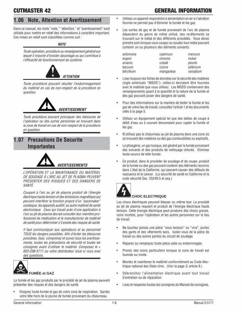
1.06 Note, Attention et AvertissementDanscemanuel,lesmots“note,”“attention,”et“avertissement”sontutilisés pour mettre en relief des informations à caractère important. Ces mises en relief sont classifiées comme suit :
NOTE
Toute opération, procédure ou renseignement général sur lequel il importe d’insister davantage ou qui contribue à l’efficacité de fonctionnement du système.
ATTENTION
Toute procédure pouvant résulter l’endommagement du matériel en cas de non-respect de la procédure en question.
! AVERTISSEMENT
Toute procédure pouvant provoquer des blessures de l’opérateur ou des autres personnes se trouvant dans la zone de travail en cas de non-respect de la procédure en question.
1.07 Precautions De Securite Importantes
! AVERTISSEMENTS
L’OPÉRATION ET LA MAINTENANCE DU MATÉRIEL DE SOUDAGE À L’ARC AU JET DE PLASMA PEUVENT PRÉSENTER DES RISQUES ET DES DANGERS DE SANTÉ.
Coupant à l’arc au jet de plasma produit de l’énergie électrique haute tension et des émissions magnétique qui peuventinterférerlafonctionpropred’un“pacemaker”cardiaque, les appareils auditif, ou autre matériel de santé electronique. Ceux qui travail près d’une application à l’arc au jet de plasma devrait consulter leur membre pro-fessionel de médication et le manufacturier de matériel de santé pour déterminer s’il existe des risques de santé.
Il faut communiquer aux opérateurs et au personnel TOUS les dangers possibles. Afin d’éviter les blessures possibles, lisez, comprenez et suivez tous les avertisse-ments, toutes les précautions de sécurité et toutes les consignes avant d’utiliser le matériel. Composez le + 603-298-5711 ou votre distributeur local si vous avez des questions.
FUMÉE et GAZ
La fumée et les gaz produits par le procédé de jet de plasma peuvent présenter des risques et des dangers de santé.
• Eloigneztoutefuméeetgazdevotrezonederespiration.Gardezvotre tête hors de la plume de fumée provenant du chalumeau.
• Utilisezunappareilrespiratoireàalimentationenairsil’aérationfournie ne permet pas d’éliminer la fumée et les gaz.
• Les sortes de gaz et de fumée provenant de l’arc de plasma dépendent du genre de métal utilisé, des revêtements se trouvant sur le métal et des différents procédés. Vous devez prendre soin lorsque vous coupez ou soudez tout métal pouvant contenir un ou plusieurs des éléments suivants:
antimoine cadmium mercure argent chrome nickel arsenic cobalt plomb baryum cuivre sélénium béryllium manganèse vanadium
• Liseztoujourslesfichesdedonnéessurlasécuritédesmatières(sigle américain “MSDS”); celles-ci devraient être fourniesavec le matériel que vous utilisez. Les MSDS contiennent des renseignements quant à la quantité et la nature de la fumée et des gaz pouvant poser des dangers de santé.
• Pourdesinformationssurlamanièredetesterlafuméeetlesgaz de votre lieu de travail, consultez l’article 1 et les documents cités à la page 5.
• Utilisezunéquipementspécialtelquedestablesdecoupeàdébit d’eau ou à courant descendant pour capter la fumée et les gaz.
• N’utilisezpaslechalumeauaujetdeplasmadansunezoneoùse trouvent des matières ou des gaz combustibles ou explosifs.
• Lephosgène,ungaztoxique,estgénéréparlafuméeprovenantdes solvants et des produits de nettoyage chlorés. Eliminez toute source de telle fumée.
• Ceproduit,dansleprocéderdesoudageetdecoupe,produitde la fumée ou des gaz pouvant contenir des éléments reconnu dans L’état de la Californie, qui peuvent causer des défauts de naissance et le cancer. (La sécurité de santé en Californie et la code sécurité Sec. 25249.5 et seq.)
CHOC ELECTRIQUE
Les chocs électriques peuvent blesser ou même tuer. Le procédé au jet de plasma requiert et produit de l’énergie électrique haute tension. Cette énergie électrique peut produire des chocs graves, voire mortels, pour l’opérateur et les autres personnes sur le lieu de travail.
• Netouchezjamaisunepièce“soustension”ou“vive”;portezdes gants et des vêtements secs. Isolez-vous de la pièce de travail ou des autres parties du circuit de soudage.
• Réparezouremplaceztoutepièceuséeouendommagée.
• Prenez des soins particuliers lorsque la zone de travail esthumide ou moite.
• MontezetmaintenezlematérielconformémentauCodeélec-trique national des Etats-Unis. (Voir la page 5, article 9.)
• Débranchez l’alimentation électrique avant tout travaild’entretien ou de réparation.
• LisezetrespecteztouteslesconsignesduManueldeconsignes.

GENERAL INFORMATION CUTMASTER 42
Manual 0-5171 1-7 General information
INCENDIE ET EXPLOSION
Les incendies et les explosions peuvent résulter des scories chaudes, des étincelles ou de l’arc de plasma. Le procédé à l’arc de plasma
produit du métal, des étincelles, des scories chaudes pouvant mettre le feu aux matières combustibles ou provoquer l’explosion de fumées inflammables.
• Soyez certain qu’aucunematière combustible ou inflammablene se trouve sur le lieu de travail. Protégez toute telle matière qu’il est impossible de retirer de la zone de travail.
• Procurezunebonneaérationdetouteslesfuméesinflammablesou explosives.
• Ne coupezpas et ne soudezpas les conteneurs ayant purenfermer des matières combustibles.
• Prévoyezuneveilled’incendielorsdetouttravaildansunezoneprésentant des dangers d’incendie.
• Legashydrogènepeut se formerou s’accumuler sous lespièces de travail en aluminium lorsqu’elles sont coupées sous l’eau ou sur une table d’eau. NE PAS couper les alliages en aluminium sous l’eau ou sur une table d’eau à moins que le gas hydrogène peut s’échapper ou se dissiper. Le gas hydrogène accumulé explosera si enflammé.
BRUIT
Le bruit peut provoquer une perte permanente de l’ouïe. Les procédés de soudage à l’arc de plasma peuvent provoquer des niveaux sonores supérieurs aux limites normalement acceptables. Vous dú4ez vous protéger les oreilles contre les bruits forts afin d’éviter une perte permanente de l’ouïe.
• Pourprotégervotreouïecontrelesbruitsforts,portezdestamponsprotecteurs et/ou des protections auriculaires. Protégez également les autres personnes se trouvant sur le lieu de travail.
• Ilfautmesurerlesniveauxsonoresafind’assurerquelesdécibels(le bruit) ne dépassent pas les niveaux sûrs.
• Pourdesrenseignementssurlamanièredetesterlebruit,con-sultez l’article 1.
RAYONS D’ARC DE PLASMA
Les rayons provenant de l’arc de plasma peuvent blesser vos yeux et brûler votre peau. Le procédé à l’arc de plasma produit une lumière infra-rouge et des rayons ultra-violets très forts. Ces rayons d’arc nuiront à vos yeux et brûleront votre peau si vous ne vous protégez pas correctement.
• Pourprotégervosyeux,porteztoujoursuncasqueouunécrande soudeur. Portez toujours des lunettes de sécurité munies de parois latérales ou des lunettes de protection ou une autre sorte de protection oculaire.
• Portez des gants de soudeur et un vêtement protecteurapproprié pour protéger votre peau contre les étincelles et les rayons de l’arc.
• Maintenez votre casque et vos lunettes deprotection enbonétat. Remplacez toute lentille sale ou comportant fissure ou rognure.
• Protégezlesautrespersonnessetrouvantsurlazonedetravailcontre les rayons de l’arc en fournissant des cabines ou des écrans de protection.
• Uti l isez la nuance de lenti l le qui est suggèrée dans lerecommendation qui suivent tableau.
NOTE
Ces valeurs s’appliquent ou l’arc actuel est observé clairement. L’experience a démontrer que les filtres moins foncés peuvent être utilisés quand l’arc est caché par moiceau de travail.

CUTMASTER 42 GENERAL INFORMATION
General information 1-8 Manual 0-5171
1.08 Documents De ReferenceConsultez les normes suivantes ou les révisions les plus récentes ayant été faites à celles-ci pour de plus amples renseignements :
1. O S H A , N O R M E S D E S É C U R I T É D U T R AVA I L E T D E PROTECTION DE LA SANTÉ, 29CFR 1910, disponible auprès du Superintendent of Documents, U.S. Government Printing Office, Washington, D.C. 20402
2. Norme ANSI Z49.1, LA SÉCURITÉ DES OPÉRATIONS DE COUPE ET DE SOUDAGE, disponible auprès de la Société Américaine de Soudage (American Welding Society), 550 N.W. LeJeune Rd., Miami, FL 33126
3. NIOSH, LA SÉCURITÉ ET LA SANTÉ LORS DES OPÉRATIONS DE COUPE ET DE SOUDAGE À L’ARC ET AU GAZ, disponible auprès du Superintendent of Documents, U.S. Government Printing Office, Washington, D.C. 20402
4. Norme ANSI Z87.1, PRATIQUES SURES POUR LA PROTECTION DES YEUX ET DU VISAGE AU TRAVAIL ET DANS LES ECOLES, disponible de l’Institut Américain des Normes Nationales (American National Standards Institute), 1430 Broadway, New York, NY 10018
5. Norme ANSI Z41.1, NORMES POUR LES CHAUSSURES PROTECTRICES, disponible auprès de l’American National Standards Institute, 1430 Broadway, New York, NY 10018
6. Norme ANSI Z49.2, PRÉVENTION DES INCENDIES LORS DE L’EMPLOI DE PROCÉDÉS DE COUPE ET DE SOUDAGE, disponible auprès de l’American National Standards Institute, 1430 Broadway, New York, NY 10018
7. Norme A6.0 de l’Association Américaine du Soudage (AWS), LE SOUDAGE ET LA COUPE DE CONTENEURS AYANT RENFERMÉ DES PRODUITS COMBUSTIBLES, disponible auprès de la American Welding Society, 550 N.W. LeJeune Rd., Miami, FL 33126
8. Norme 51 de l’Association Américaine pour la Protection contre les Incendies (NFPA), LES SYSTEMES À GAZ AVEC ALIMENTATION EN OXYGENE POUR LE SOUDAGE, LA COUPE ET LES PROCÉDÉS ASSOCIÉS, disponible auprès de la National Fire Protection Association, Batterymarch Park, Quincy, MA 02269
9. Norme 70 de la NFPA, CODE ELECTRIQUE NATIONAL, disponible auprès de la National Fire Protection Association, Batterymarch Park, Quincy, MA 02269
10. Norme 51B de la NFPA, LES PROCÉDÉS DE COUPE ET DE SOUDAGE, disponible auprès de la National Fire Protection Association, Batterymarch Park, Quincy, MA 02269
11. Brochure GCA P-1, LA MANIPULATION SANS RISQUE DES GAZ COMPRIMÉS EN CYLINDRES, disponible auprès de l’Association des Gaz Comprimés (Compressed Gas Association), 1235 Jefferson Davis Highway, Suite 501, Arlington, VA 22202
12. Norme CSA W117.2, CODE DE SÉCURITÉ POUR LE SOUDAGE ET LA COUPE, disponible auprès de l’Association des Normes Canadiennes, Standards Sales, 178 Rexdale Boulevard, Rexdale, Ontario, Canada, M9W 1R3
13. Livret NWSA, BIBLIOGRAPHIE SUR LA SÉCURITÉ DU SOUDAGE, disponible auprès de l’Association Nationale de Fournitures de Soudage (National Welding Supply Association), 1900 Arch Street, Philadelphia, PA 19103
14. Norme AWSF4.1 de l’Association Américaine de Soudage, RECOMMANDATIONS DE PRATIQUES SURES POUR LA PRÉPARATION À LA COUPE ET AU SOUDAGE DE CONTENEURS ET TUYAUX AYANT RENFERMÉ DES PRODUITS DANGEREUX , disponible auprès de la American Welding Society, 550 N.W. LeJeune Rd., Miami, FL 33126
15. N o r m e A N S I Z 8 8 . 2 , P R AT I Q U E S D E P R O T E C T I O N RESPIRATOIRE, disponible auprès de l’American National Standards Institute, 1430 Broadway, New York, NY 10018

GENERAL INFORMATION CUTMASTER 42
Manual 0-5171 1-9 General information
1.09 Declaration of ConformityManufacturer: Victor Technologies Company
Address: 82 Benning Street
West Lebanon, New Hampshire 03784
USA
The equipment described in this manual conforms to all applicable aspects and regulations of the ‘Low Voltage Directive’ (European Council Directive 2006/95/EC) and to the National legislation for the enforcement of this Directive.
The power supply equipment described in this manual conforms to CSA E60974-1 and the plasma torch equipment described in this manual conforms to CSA E60974-7.
The equipment described in this manual conforms to all applicable aspects and regulations of the "EMC Directive" (European Council Directive 2004/108/EC) and to the National legislation for the enforcement of this Directive.
Serial numbers are unique with each individual piece of equipment and details description, parts used to manufacture a unit and date of manufacture.
National Standard and Technical Specifications
The product is designed and manufactured to a number of standards and technical requirements. Among them are:
* CSA (Canadian Standards Association) standard C22.2 number 60 for Arc welding equipment.
* UL (Underwriters Laboratory) rating 94VO flammability testing for all printed-circuit boards used.
* CENELEC EN50199 EMC Product Standard for Arc Welding Equipment.
* ISO/IEC 60974-1 (BS 638-PT10) (EN 60 974-1) (EN50192) (EN50078) applicable to plasma cutting equipment and associated accessories.
* 2002/95/EC RoHS directive.
* AS60974.1 Arc Welding Equipment Welding Power Sources.
For environments with increased hazard of electrical shock, Power Supplies bearing the S mark conform to EN50192 when used in conjunction with hand torches with exposed cutting tips, if equipped with properly installed standoff guides.
* Extensive product design verification is conducted at the manufacturing facility as part of the routine design and manufacturing process. This is to ensure the product is safe, when used according to instructions in this manual and related industry standards, and performs as specified. Rigorous testing is incorporated into the manufacturing process to ensure the manufactured product meets or exceeds all design specifications.
Victor Technologies has been manufacturing products for more than 30 years, and will continue to achieve excellence in our area of manufacture.
3163339
Certified to CSASTD. E60974-1-00
CUTMASTER 42 GENERAL INFORMATION
General information 1-10 Manual 0-5171
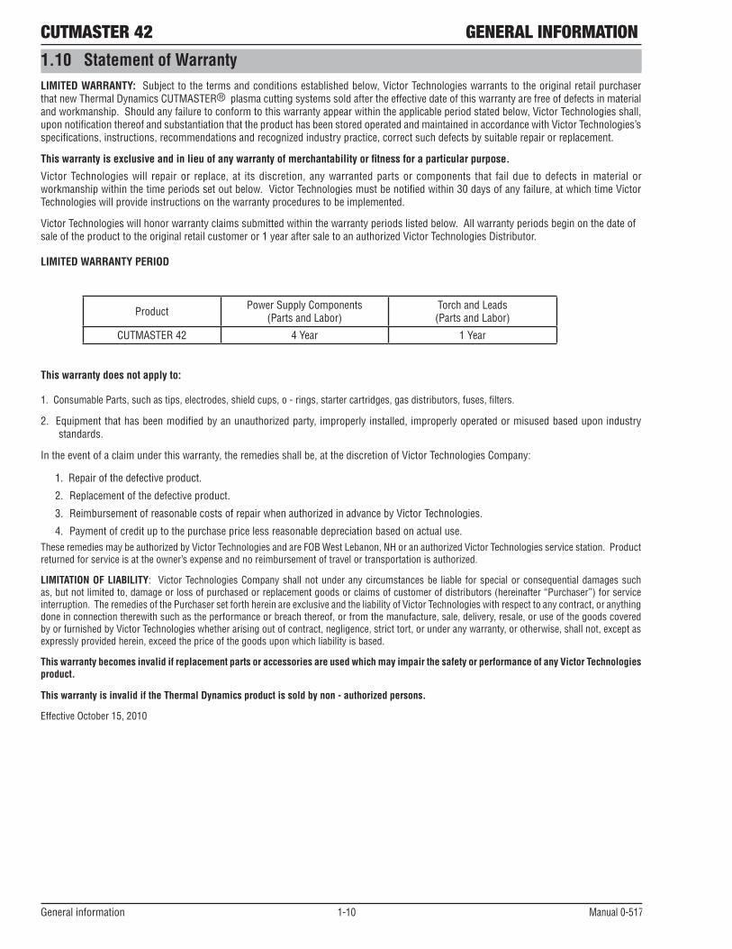
1.10 Statement of WarrantyLIMITED WARRANTY: Subject to the terms and conditions established below, Victor Technologies warrants to the original retail purchaser that new Thermal Dynamics CUTMASTER® plasma cutting systems sold after the effective date of this warranty are free of defects in material and workmanship. Should any failure to conform to this warranty appear within the applicable period stated below, Victor Technologies shall, upon notification thereof and substantiation that the product has been stored operated and maintained in accordance with Victor Technologies’s specifications, instructions, recommendations and recognized industry practice, correct such defects by suitable repair or replacement.
This warranty is exclusive and in lieu of any warranty of merchantability or fitness for a particular purpose.
Victor Technologies will repair or replace, at its discretion, any warranted parts or components that fail due to defects in material or workmanship within the time periods set out below. Victor Technologies must be notified within 30 days of any failure, at which time Victor Technologies will provide instructions on the warranty procedures to be implemented.
Victor Technologies will honor warranty claims submitted within the warranty periods listed below. All warranty periods begin on the date of sale of the product to the original retail customer or 1 year after sale to an authorized Victor Technologies Distributor.
LIMITED WARRANTY PERIOD
Product Power Supply Components(Parts and Labor)
Torch and Leads(Parts and Labor)
CUTMASTER 42 4 Year 1 Year
This warranty does not apply to:
1. Consumable Parts, such as tips, electrodes, shield cups, o - rings, starter cartridges, gas distributors, fuses, filters.
2. Equipment that has been modified by an unauthorized party, improperly installed, improperly operated or misused based upon industry standards.
In the event of a claim under this warranty, the remedies shall be, at the discretion of Victor Technologies Company:
1. Repair of the defective product.
2. Replacement of the defective product.
3. Reimbursement of reasonable costs of repair when authorized in advance by Victor Technologies.
4. Payment of credit up to the purchase price less reasonable depreciation based on actual use.These remedies may be authorized by Victor Technologies and are FOB West Lebanon, NH or an authorized Victor Technologies service station. Product returned for service is at the owner’s expense and no reimbursement of travel or transportation is authorized.
LIMITATION OF LIABILITY: Victor Technologies Company shall not under any circumstances be liable for special or consequential damages such as,butnotlimitedto,damageorlossofpurchasedorreplacementgoodsorclaimsofcustomerofdistributors(hereinafter“Purchaser”)forserviceinterruption. The remedies of the Purchaser set forth herein are exclusive and the liability of Victor Technologies with respect to any contract, or anything done in connection therewith such as the performance or breach thereof, or from the manufacture, sale, delivery, resale, or use of the goods covered by or furnished by Victor Technologies whether arising out of contract, negligence, strict tort, or under any warranty, or otherwise, shall not, except as expressly provided herein, exceed the price of the goods upon which liability is based.
This warranty becomes invalid if replacement parts or accessories are used which may impair the safety or performance of any Victor Technologies product.
This warranty is invalid if the Thermal Dynamics product is sold by non - authorized persons.
Effective October 15, 2010

INTRODUCTION CUTMASTER 42
Manual 0-5171 2-1 Introduction
SECTION 2 SYSTEM: INTRODUCTION
2.01 How to Use This ManualTo ensure safe operation, read the entire manual, including the chapter on safety instructions and warnings. Through-out this manual, the word WARNING, CAUTION and NOTE may appear. Pay particular attention to the information provided under these headings. These special annotations are easily recognized as follows:
! WARNING
Gives information regarding possible personal injury. Warnings will be enclosed in a box such as this.
CAUTIONRefers to possible equipment damage. Cau-tions will be shown in bold type.
NOTEOffers helpful information concerning certain operating procedures. Notes will be shown in italics
You will also notice icons from the safety section appear-ing throughout the manual. These are to advise you of specific types of hazards or cautions related to the por-tion of information that follows. Some may have multiple hazards that apply and would look something like this:
2.02 Equipment IdentificationThe unit’s identification number (specification or part number), model, and serial number usually appear on a nameplate attached to the machine. Equipment which does not have a nameplate attached to the machine is identi-fied only by the specification or part number printed on the shipping container. Record these numbers for future reference.
2.03 Receipt of EquipmentWhen you receive the equipment, check it against the invoice to make sure it is complete and inspect the equip-ment for possible damage due to shipping. If there is any damage, notify the carrier immediately to file a claim. Furnish complete information concerning damage claims or shipping errors to the location in your area listed in the inside back cover of this manual. Include all equipment identification numbers as described above along with a full description of the parts in error.
2.04 Transportation Methods
!Disconnect input power con-
ductors from de-energized supply line before moving the cutting power source.Lift unit with handle on top of case. Use handcart or similar device of adequate capacity. If using a fork lift vehicle, secure the unit on a proper skid before transporting.
2.05 Working Principle
Rectifier Inverter Transformer Rectifier
Reduce pressure, filter Gas valve Cutting torch Workpiece
Compressed air
Art # A-09204_AB

CUTMASTER 42 INTRODUCTION
Introduction 2-2 Manual 0-5171
2.06 Power Supply Features
Air Inlet
Control Panel
Torch Lead
120/230 VAC Power Source
Work Cable and Clamp
Art # A-09334_AC
CUTMASTER ®42
120V 15A120V 20A230V 20A
A
24
4020
20
30
27
Art# A-09335
Air InletOn/OffSwitch
Power Cord

INTRODUCTION CUTMASTER 42
Manual 0-5171 2T-1 Introduction
SECTION 2TORCH: INTRODUCTION
2T.01 Scope of ManualThis manual contains descriptions, operating instruc-tions and maintenance procedures for the SL40 Plasma Cutting Torch. Service of this equipment is restricted toproperlytrainedpersonnel;unqualifiedpersonnelarestrictly cautioned against attempting repairs or adjust-ments not covered in this manual, at the risk of voiding the Warranty. Read this manual thoroughly. A complete understanding of the characteristics and capabilities of this equipment will assure the dependable operation for which it was designed.
2T.02 Specifications
A. Torch Configurations
1. Hand Torch, Model SL40
The hand torch head is at 75° to the torch handle. The hand torches include a torch handle and torch trigger assembly.
8.3" (210.82mm)
2.6" (66.04mm)
.96" (24.38mm)
Art # A-09336
B. Torch Leads Lengths
Hand Torches are available as follows:
• 15ft/4.6m.
C. Torch Parts
Starter Cartridge, Electrode, Tip, Shield Cup
D. Parts - In - Place (PIP)
Torch has built-in switch.
12 vdc circuit rating
E. Type Cooling
Combination of ambient air and gas stream through torch.
F. Torch Ratings
SL40 Torch RatingsAmbient
Temperature104° F 40° C
Duty Cycle 100% @ 40 Amps @ 193 scfhMaximum Current 40 Amps
Voltage (Vpeak) 500VArc Striking Voltage 500VTorch Control Circuit
Voltage 24V
G. Current Ratings
SL40 Current Ratings
SL40 Torch & Leads Up to 40 Amps, DC, Straight Polarity
NOTE
Power Supply characteristics will determine material thickness range.
H. Gas Requirements
SL40 Torch Gas Specifications
Gas (Plasma and Secondary) Compressed Air
Minimum Input Pressure 85 psi 5.9 bar
Maximum Input Pressure 125 psi / 8.6 bar
Gas Flow 193 scfh 91 lpm
! WARNING
This torch is not to be used with oxygen (O2). This torch is not to be use with high frequency starting systems.

CUTMASTER 42 INTRODUCTION
Introduction 2T-2 Manual 0-5171
2T.03 Introduction to Plasma
A. Plasma Gas Flow
Plasma is a gas which has been heated to an ex-tremely high temperature and ionized so that it be-comes electrically conductive. The plasma arc cutting and gouging processes use this plasma to transfer an electrical arc to the workpiece. The metal to be cut or removed is melted by the heat of the arc and then blown away.
While the goal of plasma arc cutting is separation of the material, plasma arc gouging is used to remove metals to a controlled depth and width.
In a Plasma Cutting Torch a cool gas enters Zone B, where a arc between the electrode and the torch tip heats and ionizes the gas. The main cutting arc then transfers to the workpiece through the column of plasma gas in Zone C.
By forcing the plasma gas and electric arc through a small orifice, the torch delivers a high concentration of heat to a small area. The stiff, constricted plasma arc is shown in Zone C. Direct current (DC) straight polarity is used for plasma cutting, as shown in the illustration.
Zone A channels a secondary gas that cools the torch. This gas also assists the high velocity plasma gas in blowing the molten metal out of the cut allowing for a fast, slag - free cut.
A-00002
Workpiece
PowerSupply
+
_
C
B
A
Typical Torch Head Detail
B. Gas Distribution
The single gas used is internally split into plasma and secondary gases.
The plasma gas flows into the torch through the negative lead, through the starter cartridge, around the electrode, and out through the tip orifice.
The secondary gas flows down around the outside of the torch starter cartridge, and out between the tip and shield cup around the plasma arc.
C. Pilot Arc
When the torch is started a pilot arc is established between the electrode and cutting tip. This pilot arc creates a path for the main arc to transfer to the work.
D. Main Cutting Arc
DC power is also used for the main cutting arc. The negative output is connected to the torch electrode through the torch lead. The positive output is con-nected to the workpiece via the work cable and to the torch through a pilot wire.
E. Parts - In - Place (PIP)
The torch includes a 'Parts - In - Place' (PIP) circuit. When the shield cup is properly installed, it closes a switch. The torch will not operate if this switch is open.
Torch Trigger
PIP Switch Shield Cup
To ControlCable Wiring
Torch Switch
A-09595
Parts - In - Place Circuit Diagram for Hand Torch

INSTALLATION CUTMASTER 42
Manual 0-5171 3-1 Installation
SECTION 3: INSTALLATION
3.01 Unpacking1. Use the packing lists to identify and account for each item.
A. Contents List Description Quantity CM42 Power source 1 10ft power input cable (installed) 1 120VAC Adapter Pigtail 15A 1 120VAC Adapter Pigtail 20A 1 Work cable and clamp (installed) 1 SL40 Torch (15ft(4.6m)) w/consumables 1 Carry case 1 40A Tip Drag 2 20A Tip Drag 2 40A Tip, Standoff 2 Electrode 2 Gloves 1 Cutting Glasses 1 1/4" Pipe Size NPT female × BSPT male adapter 1
2. Inspect each item for possible shipping damage. If damage is evident, contact your distributor and / or shipping company before proceeding with the installation.
3. Record Power Supply and Torch model and serial numbers, purchase date and vendor name, in the information block at the front of this manual.
3.02 Lifting OptionsThe Power Supply includes a handle for hand lifting only. Be sure unit is lifted and transported safely and securely.
WARNING
Do not touch live electrical parts.
Disconnect input power cord before moving unit.
FALLING EQUIPMENT can cause serious personal injury and can damage equipment.
HANDLE is not for mechanical lifting.
• Onlypersonsofadequatephysicalstrengthshouldlifttheunit.• Liftunitbythehandle,usingtwohands.Donotusestrapsforlifting.
• Useoptionalcartorsimilardeviceofadequatecapacitytomoveunit.
• Placeunitonaproperskidandsecureinplacebeforetransportingwithaforkliftorothervehicle.

CUTMASTER 42 INSTALLATION
Installation 3-2 Manual 0-5171
3.03 Primary Input Power Connections
Power Cords Included With Power Supply
Attached to the power supply is an input power cord with a 230 Volt 50 Amp NEMA 6-50P for plug. Supplied adapters allow for connection of the power supply input cable plug for when using 120V input power.
Art# A-09432_AB
Figure 3-1 120VAC Adapter Pigtail
CAUTION
Check your power source for correct voltage before plugging in or connecting the unit. The primary power source, fuse, and any extension cords used must conform to local electrical code and the recommended circuit protection and wiring requirements as specified in Section 2.
Input Voltage (VAC) Rated Output Amps (RMS) input at rated out-put, 60 Hz, single-phase kVA
120V, 15A Circuit 20A, 88V 20.4 2.5120V, 20A Circuit 27A, 91V 28.5 3.5120V, 30A Circuit 27A, 91V 28.5 3.5
208-230V, 20A Circuit 40A, 96V 23-21.4 4.8

INSTALLATION CUTMASTER 42
Manual 0-5171 3-3 Installation
3.04 Air Supply Connections
A. Connecting Air Supply to Unit
The connection is the same for compressed air or industrial compressed air in gas cylinders. 1. Connect the gas line to the compressed air inlet port at the appropriate pressure.
Art# A-09337
Air Inlet
On/OffSwitch
Figure 3-2 Gas Connection to Compressed Air input
B. Using Industrial Compressed Air In Gas Cylinders
When using Industrial compressed air in gas cylinders as the gas supply:1. Refer to the manufacturer’s specifications for installation and maintenance procedures for high pressure gas
regulators.
2. Examine the cylinder valves to be sure they are clean and free of oil, grease or any foreign material. Briefly open each cylinder valve to blow out any dust which may be present.
3. The cylinder must be equipped with an adjustable high - pressure regulator capable of outlet pressures up to 100 psi (6.9 bar) maximum and flows of at least 250 scfh (120 lpm).
4. Connect gas supply hose to the cylinder.
NOTE
Pressure should be set at 100 psi (6.9 bar) at the high pressure gas cylinder regulator.
Supply hose must be at least 1/4 inch (6 mm) I.D.
For a secure seal, apply thread sealant to the fitting threads, according to manufacturer's instructions. Do Not use Teflon tape as a thread sealer, as small particles of the tape may break off and block the small gas passages in the torch.

CUTMASTER 42 INSTALLATION
Installation 3-4 Manual 0-5171
3.05 Power Supply Specifications
CUTMASTER 42 Power Supply SpecificationsInput Power 120 VAC (+-10%), 1Phase, 50/60Hz
208-230 VAC (+-10%), 1Phase, 50/60HzOutput Current 20 Amps @ 120VAC, 15A
20-27 Amps @ 120VAC, 20A20-40 Amps @ 230VAC, 20A
CUTMASTER 42 Power Supply Duty Cycle (Note 1)Ambient Temperature 104° F (40° C)Duty Cycle 30% @ 120VAC, 40% @ 230VACRated Current 27 Amps @ 120VAC, 40 Amps @ 230V
SL40 Torch Gas Requirements (see section 2T.03)Notes
1. Duty Cycle is the percentage of time the system can be operated without overheating. Duty cycle is reduced if primary input voltage (AC) is low or the DC voltage is higher than shown in this chart.2. Air supply must be free of oil, moisture, and other contaminants. Excessive oil and moisture may cause double-arcing, rapid tip wear, or even complete torch failure. Contaminants may cause poor cutting performance and rapid electrode wear. Optional filters provide increased filtering capabili-ties.
NOTE
IEC Rating is determined as specified by the International Electro-Technical Commission. These specifica-tions include calculating an output voltage based upon power supply rated current. To facilitate comparison between power supplies, all manufacturers use this output voltage to determine duty cycle.
TDC Rating is determined using an output voltage representative of actual output voltage during cutting with a TDC torch. This voltage may be more or less than IEC voltage, depending upon choice of torch, consumables, and actual cutting operation.

INSTALLATION CUTMASTER 42
Manual 0-5171 3-5 Installation
Art# A-09333_AC
26lb / 11.8kg
7" (177mm)
18.5" (469.9mm)
9" (228.6mm)
CUTMASTER ®42
120V 15A120V 20A230V 20A
A
24
4020
20
30
27
Figure 2-1 Power Supply Dimensions & Weight
NOTE
Weight includes torch & leads, input power cord, and work cable with clamp.
CAUTION
Provide clearance for proper air flow through the power supply. Operation without proper air flow will inhibit proper cooling and reduce duty cycle.
CUTMASTER 42 INSTALLATION
Installation 3-6 Manual 0-5171
3.06 Input Wiring Specifications
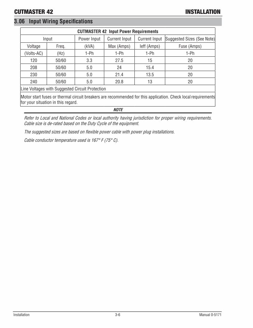
CUTMASTER 42 Input Power Requirements
Input Power Input Current Input Current Input Suggested Sizes (See Note)
Voltage Freq. (kVA) Max (Amps) Ieff (Amps) Fuse (Amps)
(Volts-AC) (Hz) 1-Ph 1-Ph 1-Ph 1-Ph
120 50/60 3.3 27.5 15 20
208 50/60 5.0 24 15.4 20
230 50/60 5.0 21.4 13.5 20
240 50/60 5.0 20.8 13 20
Line Voltages with Suggested Circuit Protection
Motor start fuses or thermal circuit breakers are recommended for this application. Check local requirements for your situation in this regard.
NOTE
Refer to Local and National Codes or local authority having jurisdiction for proper wiring requirements. Cable size is de-rated based on the Duty Cycle of the equipment.
The suggested sizes are based on flexible power cable with power plug installations.
Cable conductor temperature used is 167° F (75° C).

OPERATION CUTMASTER 42
Manual 0-5171 4-1 Operation
SECTION 4 SYSTEM: OPERATION
4.01 Control Panel
Art# A-09338-AD
CUTMASTER®42
AC Indicator
The Front Panel The Rear Panel
Overheat Indicator
Air Indicator
DC Indicator (Ready)Air Inlet
On/OffSwitch
Power Cord
A
120V 15A120V 20A230V 20A
24
4020
20
30
27
1. ON / OFF Switch (Power Switch/Lamp)
Controls input power to the power supply. I is ON (Red Lamp), O is OFF.
2. (A) Output Current Control
Sets the desired output current. If the overload protection (fuse or circuit breaker) on the input power circuit opens frequently, either reduce cutting output, reduce the cutting time, or connect the unit to more adequate input power. Note: For 120V input power, the unit will automatically limit the output current to a maximum of 27A. For 230V input power, the maximum output is 40 Amps. Refer to Section 2 for input power requirements.
3. AC Indicator
Steady light indicates power supply is ready for operation.
4. OVERHEAT Indicator (TEMP Indicator)
Indicator is normally OFF. Indicator is ON when internal temperature exceeds normal limits. Allow the unit to run with the fan on until the temp indicator turns off.
5. AIR Indicator
AIR light should be ON when there is sufficient gas pressure.
6. READY (DC Indicator)
Indicator is ON when DC output circuit is active.

CUTMASTER 42 OPERATION
Operation 4-2 Manual 0-5171
NOTE
All consumables must be correctly installed and maintained to ensure correct operation.
4.02 Preparations For OperatingAt the start of each operating session:
WARNING
Disconnect primary power at the source before assembling or disassembling power supply, torch parts, or torch and leads assemblies.
A. Torch Parts Selection
Check the torch for proper assembly and appropriate torch parts. The torch parts must correspond with the type of operation, and with the amperage output of this power supply (40 amps maximum). Use only genuine Thermal Dynamics parts with this torch.
Art # A-09340-AG
Start Cartridge, Cat. No. 9-0097
Electrode, Cat. No. 9-0096
Worn Electrode Worn Tip
40 Amp Drag Tip, Cat. No. 9-0093
Shield Cup, Cat. No. 9-0098
40 Amp Standoff Tip, Cat. No. 9-0094
NOTE
When operating the torch in a normal condition, some gas vents through the gap between the shield cup and torch handle. Do not attempt to over tighten the shield cup as irreparable damage to internal compo-nents may result.
NOTE
For 115VAC, 20A Drag Cutting Tip ( Cat.No. 9-0091) shall be used (refer to 9.03 SL40 Replacement Parts).

OPERATION CUTMASTER 42
Manual 0-5171 4-3 Operation
B. Torch Connection
Check that the torch is properly connected.
C. Check Primary Input Power Source
1. Check the power source for proper input voltage. Make sure the input power source meets the power require-ments for the unit per Section 2, Specifications.
2. Connect the input power cable (or close the main disconnect switch) to supply power to the system.D. Gas Selection
Ensure gas source meets requirements listed in section 2T. Check connections and turn gas supply on.
E. Connect Work Cable
Clamp the work cable to the workpiece or cutting table. The area must be free from oil, paint and rust. Connect onlytothemainpartoftheworkpiece;donotconnecttotheparttobecutoff.
Art # A-03387
F. Power On
Place the power supply ON / OFF switch to the ON (I) position. Power indicator turns on.
Art# A-09335
Air InletOn/OffSwitch
Power Cord
A
120V 15A120V 20A230V 20A
24
4020
20
30
27Art# A-09339_AD
Rear Panel with ON/OFF Switch Front Panel With Power ON/OFF Indicator

CUTMASTER 42 OPERATION
Operation 4-4 Manual 0-5171
G. Select Current Output Level
Set the desired current output level.
A
120V 15A120V 20A230V 20A
24
4020
20
30
27
120V, 15A
24
4020
20
30
27
24
4044020
20
30
727700
230V, 20A
24
2027
24
207274020
30
A
430
120V, 20A
4020
30
303030
A
24
4044020
207277
A
24
2A
4
22
04020
3024
20
AA A27
A#09697_AA
4.03 Sequence of OperationThe following is a typical sequence of operation for this power supply.
1. Place the ON / OFF switch on the power supply to ON (up) position (Red indicator lamp is illuminated).a. AC indicator turnson;fanturnson.
NOTE
During initial power up, there will be a delay of about 2 seconds before the AC Indicator light will illuminate and the pre-flow gas and fan starts. The gas will automatically flow from torch for approximately 10 seconds (only after the AC Indicator lamp is illuminated) (The AC Indicator lamp and fan turns on approximately 2 seconds after the ON/OFF switch is enabled), this is a process that makes sure all inputs (gas, input power, torch connection, and torch parts) are acknowledged for proper operation.
2. Wear protective clothing, including welding gloves and appropriate eye protection (see table 1-1). Place tip on work piece and pull trigger. Arc will initiate and start cutting material.

OPERATION CUTMASTER 42
Manual 0-5171 4-5 Operation
• Standoff Cutting With Hand TorchNOTE
For best performance and parts life, always use the correct parts for the type of operation.
A. The torch can be comfortably held in one hand or steadied with two hands. Position the hand to press the Trigger on the torch handle. With the hand torch, the hand may be positioned close to the torch head for maximum control or near the back end for maximum heat protec-tion. Choose the holding technique that feels most comfortable and allows good control and movement.
NOTE
The tip should never come in contact with the workpiece except during drag cutting opera-tions.
B. Depending on the cutting operation, do one of the following: a). For drag cutting, place the tip on the
plate holding the torch at a angle to the plate so that only one edge of the tip is in contact with the plate. This prevents dam-age to the tip during the piercing process.
b). For standoff cutting, hold the torch tip on the work piece, pull the trigger. After the arc is initiated lift the tip to 1/8" - 3/8" (3-4mm) off the work.
A-00024_AB
Shield Cup
Torch
Standoff Distance1/8" - 3/8" (3 - 9mm)
Standoff Distance
Art # A-09342
Trigger
Trigger Release
3
4
Trigger
21
Trigger Release
Art # A-11462
NOTE
When the shield cup is properly installed, there is a slight gap between the shield cup and the torch handle. Gas vents through this gap as part of normal operation. Do not attempt to force the shield cup to close this gap. Forcing the shield cup against the torch head or torch handle can damage components.
CUTMASTER 42 OPERATION
Operation 4-6 Manual 0-5171
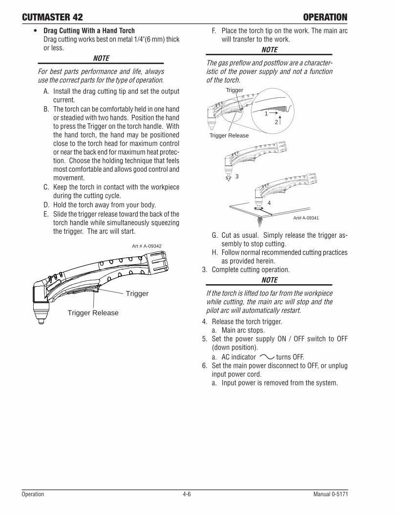
• Drag Cutting With a Hand Torch Drag cutting works best on metal 1/4"(6 mm) thick
or less.NOTE
For best parts performance and life, always use the correct parts for the type of operation.
A. Install the drag cutting tip and set the output current.
B. The torch can be comfortably held in one hand or steadied with two hands. Position the hand to press the Trigger on the torch handle. With the hand torch, the hand may be positioned close to the torch head for maximum control or near the back end for maximum heat protec-tion. Choose the holding technique that feels most comfortable and allows good control and movement.
C. Keepthetorchincontactwiththeworkpieceduring the cutting cycle.
D. Hold the torch away from your body.E. Slide the trigger release toward the back of the
torch handle while simultaneously squeezing the trigger. The arc will start.
Art # A-09342
Trigger
Trigger Release
F. Place the torch tip on the work. The main arc will transfer to the work.
NOTE
The gas preflow and postflow are a character-istic of the power supply and not a function of the torch.
3
4
Trigger
21
Trigger Release
Art# A-09341
G. Cut as usual. Simply release the trigger as-sembly to stop cutting.
H. Follow normal recommended cutting practices as provided herein.
3. Complete cutting operation.NOTE
If the torch is lifted too far from the workpiece while cutting, the main arc will stop and the pilot arc will automatically restart.
4. Release the torch trigger. a. Main arc stops.
5. Set the power supply ON / OFF switch to OFF (down position).a. AC indicator turns OFF.
6. Set the main power disconnect to OFF, or unplug input power cord.a. Input power is removed from the system.

OPERATION CUTMASTER 42
Manual 0-5171 4-7 Operation
4.04 Cut Quality
NOTE
Cut quality depends heavily on setup and parameters such as torch standoff, alignment with the workpiece, cutting speed, gas pres-sures, and operator ability.
Refer to appendix pages for additional infor-mation as related to the power supply used.
Cut quality requirements differ depending on application. For instance, nitride build-up and bevel angle may be ma-jor factors when the surface will be welded after cutting. Dross-free cutting is important when finish cut quality is desired to avoid a secondary cleaning operation. The following cut quality characteristics are illustrated in the following figure:
Kerf WidthCut SurfaceBevel Angle
Top EdgeRounding
Cut SurfaceDrag Lines
DrossBuild-Up
TopSpatter
A-00007
Cut Quality Characteristics
Cut Surface
The desired or specified condition (smooth or rough) of the face of the cut.
Nitride Build - Up
Nitride deposits can be left on the surface of the cut when nitrogen is present in the plasma gas stream. These buildups may create difficulties if the material is to be welded after the cutting process.
Bevel Angle
The angle between the surface of the cut edge and a plane perpendicular to the surface of the plate. A perfectly perpendicular cut would result in a 0° bevel angle.
Top - Edge Rounding
Rounding on the top edge of a cut due to wearing from the initial contact of the plasma arc on the workpiece.
Bottom Dross Buildup
Molten material which is not blown out of the cut area and resolidifies on the plate. Excessive dross may require secondary cleanup operations after cutting.
Kerf Width
The width of the cut (or the width of material removed during the cut).
Top Spatter (Dross)
Top spatter or dross on the top of the cut caused by slow travel speed, excess cutting height, or cutting tip whose orifice has become elongated.

CUTMASTER 42 OPERATION
Operation 4-8 Manual 0-5171
4.05 General Cutting Information
WARNING
Disconnect primary power at the source before disassembling the power supply, torch, or torch leads.
Frequently review the Important Safety Pre-cautions at the front of this manual. Be sure the operator is equipped with proper gloves, clothing, eye and ear protection. Make sure no part of the operator’s body comes into contact with the workpiece while the torch is activated.\
CAUTION
Sparks from the cutting process can cause damage to coated, painted, and other surfaces such as glass, plastic and metal.
NOTE
Handle torch leads with care and protect them from damage.
Torch Standoff
Improper standoff (the distance between the torch tip and workpiece) can adversely affect tip life as well as shield cup life. Standoff may also significantly affect the bevel angle. Reducing standoff will generally result in a more square cut.
Edge Starting
For edge starts, hold the torch perpendicular to the workpiece with the front of the tip near (not touching) the edge of the workpiece at the point where the cut is to start. When starting at the edge of the plate, do not pause at the edge and force the arc to "reach" for the edge of the metal. Establish the cutting arc as quickly as possible.
Direction of Cut
In the torches, the plasma gas stream swirls as it leaves the torch to maintain a smooth column of gas. This swirl effect results in one side of a cut being more square than the other. Viewed along the direction of travel, the right side of the cut is more square than the left.
Right SideCut Angle
Left SideCut Angle
A-00512
Side Characteristics Of Cut
To make a square - edged cut along an inside diameter of a circle, the torch should move counterclockwise around the circle. To keep the square edge along an outside diameter cut, the torch should travel in a clockwise direction.
Dross
When dross is present on carbon steel, it is com-monlyreferredtoaseither“highspeed,slowspeed,ortopdross”.Drosspresentontopoftheplateisnormally caused by too great a torch to plate distance. "Top dross" is normally very easy to remove and can often be wiped off with a welding glove. "Slow speed dross" is normally present on the bottom edge of the plate. It can vary from a light to heavy bead, but does not adhere tightly to the cut edge, and can be easily scraped off. "High speed dross" usually forms a nar-row bead along the bottom of the cut edge and is very difficult to remove. When cutting a troublesome steel, it is sometimes useful to reduce the cutting speed to produce "slow speed dross". Any resultant cleanup can be accomplished by scraping, not grinding.

Manual 0-5171 5-1 Theory of operation
THEORY OF OPERATION CUTMASTER 42
5.01 Inverter Design
What does the word inverter mean?
The term inverter refers to the ability to change DC power into AC. Inverter power supplies immediately rectify the incoming AC to DC, and then the transistors create a higher frequency AC. The higher frequency AC then goes on to a much smaller main transformer than in a conventional power supply. The AC is then rectified to extremely smooth DC. The diagram to the below shows the basic electrical wiring of a DC output inverter power supply.
Inverter Technology - Summary
Rectifier Filter IGBT Transformer Rectifier Inductor
AC-50/60Hz DC-Rippled DC-Smooth AC-23KHz AC-23KHz DC- Rippled DC-Smooth
High Voltage High Voltage High voltage High Voltage Low Voltage Low Voltage Low Voltage
Low Amperage Low Amperage Low Amperage Low Amperage High Amperage High Amperage High Amperage
Art # A-09846
SECTION 5: THEORY OF OPERATION

Theory of operation 5-2 Manual 0-5171
CUTMASTER 42 THEORY OF OPERATION
Notes

TROUBLESHOOTING CUTMASTER 42
Manual 0-5171 6-1 Troubleshooting
6.01 Basic Troubleshooting-Power Source Faults
! WARNING
There are extremely dangerous voltage and power levels present inside this unit. Do not attempt to diagnose or repair it unless you are an accredited service provider and you have had training in power electronics measurement and troubleshooting techniques.
Common Faults symptom LED Indicators
A. AC indicator OFF
1. Main input power cord does not connect to power distribution net.
a. Connect the power cord.
2. Power ON/OFF switch in OFF (down) position.
a. Turn switch to ON (up) position.
3. Actual input voltage does not correspond to voltage of unit.
a. Verify that the input line voltage is correct.
4. Faulty components in unit
a. Return for repair or have qualified technician repair per service manual.
B. AC indicator blinking
1. Indicator blinking (1 sec ON/1 Sec OFF, Gas may also pulse 3 times).
a. Check for missing torch parts or not properly installed. Turn ON/OFF switch to OFF position and restart the machine by turning the power switch to ON.
2. Indicator blinking (1 sec ON/3 Sec OFF).
a. Check for worn or sticking torch parts. Replace if necessary.
3. Indicator blinking (3 sec ON/3 Sec OFF).
a. Torch switch was depressed before machine was completely powered up. Turn ON/OFF switch to OFF position and the restart the machine by turning the power switch to ON.
C. Air indicator OFF
1. Gas pressure too low. Check supply pressure.
D. TEMP indicator ON, (AC indicator ON)
1. Unit air flow obstructed.
a. Check for blocked air flow around the unit and correct condition.
2. Fan blocked.
a. Check for blocked status and correct condition.
SECTION 6: TROUBLESHOOTING

Troubleshooting 6-2 Manual 0-5171
CUTMASTER 42 TROUBLESHOOTING3. Unit is overheated.
a. Keepthemachinepluggedinandturnedonforfiveminutes.Thiswillallowthefantorunandcoolthe machine.
4. Faulty components in unit
a. Return for repair or have qualified technician repair per service manual.
E. Torch will not pilot, when torch trigger is activated.
1. Faulty parts in torch
a. Checktorchpartspersection4.02;replaceasneeded.
2. Gas pressure too low
a. Adjust supply pressure to proper setting value.
NOTEThe pressure should be set at (100 PSI).
3. Faulty tip in use
a. In115VACoperation,40AmpTipisusedwhichpreventstheunitfrompiloting;
Replace with 20 Amp Tip.
4. Faulty components in unit
a. Return for repair or have qualified technician repair per service manual.
F. Nocuttingoutputwhentorchisactivated;ACindicator ON, gas flows, fan turns.
1. Torch is not connected properly to power supply.
a. Check torch connection to power supply.
2. Working cable not connected to work piece, or connection is poor.
a. Make sure that work cable has a proper connection to a clean, dry area of the work piece.
3. Faulty components in unit
a. Return for repair or have qualified technician repair per service manual.
4. Faulty torch
a. Return for repair or have qualified technician repair.
G. Torch cuts but not adequately
1. Incorrect setting of output current control
a. Check and adjust to proper setting.
2. Working cable connection to work piece is poor.
a. Make sure that work cable has a proper connection to a clean, dry area of the work piece.
3. Faulty components in unit
a. Return for repair or have qualified technician repair.
H. Output is restricted, and can not be controlled.
1. Input or output connection is poor.
a. Check all input and output connection leads.
2. Working cable connection to work piece is poor.
a. Make sure that work cable has a proper connection to a clean, dry area of the work piece.

TROUBLESHOOTING CUTMASTER 42
Manual 0-5171 6-3 Troubleshooting
3. Faulty components in unit
a. Return for repair or have qualified technician repair per service manual.
I. Cutting output is unstable or inadequate at 120V operation.
1. Low or fluctuating input voltage
a. Turn output current to minimum (20 amps) and suggest using 20A Drag tip.
b. Connect to a dedicated input line voltage.
c. Have electrician check input line voltage under load.
2. Input or output connection is poor
a. Check all input and output connection leads.
3. Working cable connection is poor.
a. Make sure that work cable has a proper connection to a clean, dry area of the work piece.
J. Hard to startup
1. Torch parts worn (consumables)
a. Turn off input power, remove shield cup, tip, start cartridge, and electrode and check them all. If the electrode or cutting tip is worn out, replace them. If the start cartridge does not move freely, replace it. If there is too much spatter on shield cup, replace it.
K. Arcgoesoutwhileoperating.Arccan’tberestartedwhentorchtriggerisactivated.
1. Power Supply is overheated (TEMP indicator ON).
a. Let unit cool down for at least 5 minutes. Make sure the unit has not been operated beyond duty cycle limit.
2. Fan blades blocked (TEMP indicator ON).
a. Check and clear blades.
3. Air flow blocked
a. Check for blocked air flow around the unit and correct condition.
4. Gas pressure is too low. (Air indicator ON when torch trigger is activated.)
a. Check gas source. Adjust to proper setting value.
5. Torch parts worn
a. Check torch shield cup, cutting tip, start cartridge and electrode. Replace as needed.
6. Faulty component in unit
a. Return for repair or have qualified technician repair per service manual.
L. Torch cuts but not well.
1. Current control is set too low.
a. Increase the current setting.
2. Torch is being moved too fast across work piece
a. Reduce cutting speed.

Troubleshooting 6-4 Manual 0-5171
CUTMASTER 42 TROUBLESHOOTING3. Excessive oil or moisture in torch
a. Hold torch 1/8 inch (3 mm) from clean surface while purging and observe oil or moisture buildup (do not activate torch). If there are contaminants in the gas, additional filtering may be needed.
4. Torch parts worn
a. Check torch shield cup, cutting tip, start cartridge and electrode. Replace as needed.
M. Gas in torch pulsates 3 times and then stops. AC indicator light blinking.
1. Torch parts not properly installed in torch. There may have been an attempt to remove torch parts without turning off ON/OFF power switch to OFF on unit.
a. Check to make sure torch parts are properly installed.
b. Turn ON/OFF switch to OFF and then back to ON.
6.02 Checking Unit Before Applying Power
!
! Turn SW1 to OFF position, and disconnect unit from primary line voltage before working on unit.
! Significant DC voltage can remain on capacitors after unit is Off. Wait until all front panel LED’s are off before removing case.
! Check DC bus voltage according to Section 6.07 after removing case.
! Before troubleshooting or applying power to unit, complete the following checks to avoid causing further damage.
6.03 Tools Needed for Troubleshooting and Servicing
Art # A-09849

TROUBLESHOOTING CUTMASTER 42
Manual 0-5171 6-5 Troubleshooting
6.04 Case Removal
! Read and follow safety information in Section 6.02 before proceeding.
Remove the ten screws from the cover and remove the cover panel.
Art # A-10242
6.05 Clear Cover Sheet Removal
! Read and follow safety information in Section 6.02 before proceeding.
1. Clear protective sheet
Take out clear protective sheet.
1Art # A-10243

Troubleshooting 6-6 Manual 0-5171
CUTMASTER 42 TROUBLESHOOTING
6.06 Visually Inspect
Visually inspect the inside of the Power Source. The levels of current present in these units can cause burning or arcing of PCB, transformers, switches, or rectifier when a failure occurs. Carefully inspect all components within these units.
Look in particular for the following:
a) Loose or broken wires or connectors.
b) Burned or scorched parts or wires or evidence of arcing.
c) Any accumulation of metal dust or filings that may have caused shorting or arcing.
If any parts are damaged, they must be replaced. Refer to the Spare Parts section for a complete list of components used in the Power Source.
Locate the faulty component(s) then replace where necessary.
6.07 Preliminary DC Bus Measurement of the Main Inverter Board
! Read and follow safety information in Section 6.02 before proceeding.
DC Bus Testing Multimeter Lead Placement Voltage with Supply voltage OFF
Upper capacitor bank Positive meter lead to testpoint 30 Negative meter lead to testpoint 29 0 VDC
Lower capacitor bank Positive meter lead to testpoint 32 Negative meter lead to testpoint 31 0 VDC
Table 6-1 DC BUS, Multimeter set to measure DC volts

TROUBLESHOOTING CUTMASTER 42
Manual 0-5171 6-7 Troubleshooting
6.08 Preliminary Check of the Main Inverter Board
! Read and follow safety information in Section 6.02 before proceeding.
12
34
56
78
910
Art
# A-
1024
4
1112
1314
29
30 31
32
1615
1718
1920
2122
2324
2526

Troubleshooting 6-8 Manual 0-5171
CUTMASTER 42 TROUBLESHOOTING
IGBT Testing Multimeter Lead Placement Diode Voltage
IGBT 1Positive meter lead to test point 3
0.2000 to 0.8000 VDC Negative meter lead to test point 2
IGBT 2Positive meter lead to test point 5
0.2000 to 0.8000 VDCNegative meter lead to test point 4
IGBT 3Positive meter lead to test point 8
0.2000 to 0.8000 VDCNegative meter lead to test point 7
VIGBT 4Positive meter lead to test point 10
0.2000 to 0.8000 VDCNegative meter lead to test point 9
PFC IGBT 1Positive meter lead to test point 14
0.2000 to 0.8000 VDCNegative meter lead to test point 13
PFC IGBT2Positive meter lead to test point 12
0.2000 to 0.8000 VDCNegative meter lead to test point 11
PILOT IGBT1Positive meter lead to test point 26
0.2000 to 0.8000 VDCNegative meter lead to test point 25
Table 6-2 IGBT’s, Multimeter set to measure Diode Voltage
6.09 Check Main On / Off Switch
! Read and follow safety information in Section 6.02 before proceeding.
Art # A-10245
1
2
3
4
Power Switch Testing Multimeter Lead Placement Impedance Switch ON Positive meter lead to testpoint 1
Negative meter lead to testpoint 20 to 1 Ω
Switch ON Positive meter lead to testpoint 3 Negative meter lead to testpoint 4
0 to 1 Ω
Switch OFF Positive meter lead to testpoint 1 Negative meter lead to testpoint 2
> 1k Ω
Switch OFF Positive meter lead to testpoint 3 Negative meter lead to testpoint 4
> 1k Ω
Table 6-3 Power Switch, Multimeter set to measure ohms (Ω)

TROUBLESHOOTING CUTMASTER 42
Manual 0-5171 6-9 Troubleshooting
6.10 Check Pressure Switch1
2
Art # A-10292
1. Pressure switch open
When the pressure is up to 3.5kgf/cm2 (49.78 PSI), the pressure switch turns off.
2. Pressure switch closed
When the pressure is less than 2.4kgf/cm2 (34.13 PSI), the pressure switch turns on and the resistance between 1 and 2 is about 0.1Ω.
6.11 Check Regulator 1
Art # A-10293
When solenoid valve is on,adjusts the knob 1. If the pressure is continuously adjustable, the regulator is ok.

Troubleshooting 6-10 Manual 0-5171
CUTMASTER 42 TROUBLESHOOTING
6.12 Check Main Input RectifierDC—AC1
AC2
DC+
Art # A-10291
Input Rectifier Testing Multimeter Lead Placement Diode Voltage
AC1 to DC+ Positive meter lead to AC1 Negative meter lead to testpoint DC+
0.2 – 0.8 VDC
AC2 to DC+ Positive meter lead to AC2 Negative meter lead to testpoint DC+
0.2 – 0.8 VDC
AC1 to DC- Positive meter lead to testpoint DC- Negative meter lead to testpoint AC1
0.2 – 0.8 VDC
AC2 to DC- Positive meter lead to testpoint DC- Negative meter lead to testpoint AC2
0.2 – 0.8 VDC
Table 6-4 IGBT’s, Multimeter set to measure Diode Voltage
Measurements may be made directly onto the main input rectifier. AC1 and AC2 may be measured from the pins on the mains supply plug with the main power switch set to the ON position.
6.13 DC Bus Voltage Measurement
Apply voltage to the Power Source.
There are extremely dangerous voltage and power levels present inside these Power Sources. Do not attempt to diagnose or repair unless you have had training in power electronics measurement and troubleshoot-ing techniques.
Once power is applied to the Power Source, there are extremely hazardous voltage and power levels present.
Do not touch any live parts.

TROUBLESHOOTING CUTMASTER 42
Manual 0-5171 6-11 Troubleshooting
12
34
56
78
910
Art
# A-
1024
4
1112
1314
29
30 31
32
1615
1718
1920
2122
2324
2526

Troubleshooting 6-12 Manual 0-5171
CUTMASTER 42 TROUBLESHOOTING
DC Bus Testing Multimeter Lead Placement Voltage with Supply voltage ON
Upper capacitor bank Positive meter lead to testpoint 30 Negative meter lead to testpoint 29 192 VDC +/-10%
Lower capacitor bank Positive meter lead to testpoint 31 Negative meter lead to testpoint 32 192 VDC +/-10%
Overall capacitor bank Positive meter lead to testpoint 29 Negative meter lead to testpoint 32 384 VDC +/-10%
Table 6-5 DC BUS, Multimeter set to measure DC volts
Note: These DC voltages are at nominal mains supply voltage of 240VAC.

TROUBLESHOOTING CUTMASTER 42
Manual 0-5171 6-13 Troubleshooting
6.14 Check of Control PCB
! Read and follow safety information in Section 6.02 before proceeding.
J1(H
F/QF
)J2
(MB)
J3(H
FOUT
)J4
(SOU
RCE&
TIP)
J5(D
RIVE
)
J6(U
_D)
J14(
GUN&
TEST
)
J13(
PRES
SURE
)
J12(
OT)
J7(W
A)Ar
t # A
-102
46J8
(FAN
)J9
(Tra
nsf I
FB)
SW1
J10(
WV)
J11(
D_po
rt)GN
D

Troubleshooting 6-14 Manual 0-5171
CUTMASTER 42 TROUBLESHOOTING
J1 Pin function signal1 GND 0VDC 2 Control circuit power source 27VDC 3 Negative of solenoid control signal 0VDC (when soleniod is on)4 Positive of solenoid control signal 27VDCJ21 Current control potentiometer 0 — 4VDC2 N/A N/A3 Fault indicator signal 2VDC (when indication lights up)4 N/A N/A5 Control circuit power supply 5VDC6 GND 0VDC7 Power indication signal 2VDC8 N/A N/A9 Work indication signal 2VDC10 Power indication signal 2VDCJ3 N/A N/AJ41 Positive of TIP test signal 5VDC 2 TIP test signal 5VDC (when machine dose no work) 0VDC
the machine is woking3 Control circuit power source 24VDC4 GND 0VDC5 Control circuit power source -24VDCJ51 Drive circuit power +15VDC2 IGBT 1 pwm drive signal 15V p-p square wave3 IGBT 2 pwm drive signal 15V p-p square wave4 IGBT 2 pwm drive signal 15V p-p square wave5 IGBT 1 pwm drive signal 15V p-p square wave6 Overcurrent signal >7VDC when over primary current protection7 GND 0VDCJ61 Feedback of input voltage 41VDC(input 230vac)
23VDC(input 115vac)2 GND 0VDCJ71 Power source of current sensor 15VDC2 Power source of current sensor -15VDC3 Output current feedback4 GND 0VDC

TROUBLESHOOTING CUTMASTER 42
Manual 0-5171 6-15 Troubleshooting
J81 Power source of fan 24VDC2 0VDC(fan negative)when fan is on 0VDCJ91 N/A N/A 2 GND 0VDC3 Pilot ARC current feedback signal -0.8VDC
+5VDC( A main cutting arc is established)J101 Positive of voltage feedback Machine output +2 Negative of voltage feedback Machine output _
J111 +12VDC +12VDC2 Pilot ARC IGBT drive signal
J121 N/A N/A2 Thermostat (0VDC when thermostat
closed)3 GND 0VDC
J131 Pressure switch signal Pressure switch(0dc when switch closed
otherwise 4VDC)2 GND 0VDC
J141 GND 0VDC2 Gun switch signal 0VDC when switch on otherwise 27VDC3 Cup test signal 0VDC4 Cup test signal 0VDC when the cup is fixed otherwise 27VDC

Troubleshooting 6-16 Manual 0-5171
CUTMASTER 42 TROUBLESHOOTING
6.15 Waveforms
1. Vds of inverter IGBT at no load
Test point C1: 4 and 5 C2: 9 and 10 (Testpoints refer to inverter PCB diagram in Sec. 6.13).
Timebase Trigger
StopPositive
Art # A-10247
2. Vds of inverter IGBT at full load
Test point C1: 4 and 5 C2: 9 and 10 (Testpoints refer to inverter PCB diagram in Sec. 6.13 ).
Timebase Trigger
StopPositive
Art # A-10248
6.16 Main Circuit Description
! Turn off power and disconnect mains supply plug from receptacle before working on the unit. Allow two minutes for capacitors to discharge after disconnection from mains supply voltage.
PFC Control Chip
AC
AC
V+
V-
U1
DC+
DC-
DC+
DC-
dc+
dc+
Art # A-10249

TROUBLESHOOTING CUTMASTER 42
Manual 0-5171 6-17 Troubleshooting
6.16 Main Circuit Description
! Turn off power and disconnect mains supply plug from receptacle before working on the unit. Allow two minutes for capacitors to discharge after disconnection from mains supply voltage.
PFC Control Chip
AC
AC
V+
V-
U1
DC+
DC-
DC+
DC-
dc+
dc+
Art # A-10249

Troubleshooting 6-18 Manual 0-5171
CUTMASTER 42 TROUBLESHOOTINGThe mains supply voltage is connected via a double pole switch to the input rectifier U1 through an EMC filter. Over-voltage protection is provided by varistor CY1.
The rectifier circuit converts the inputted AC voltage to DC voltage. The input current is controlled through being compared with reference wave. The reference point is a pure sine wave which derives from the source voltage. The PFC control chip will be used to generate suitable gate signal to drive V8 and V8-1, ensuring the current is sinusoidal.
The boost diode output charges the main capacitor bank (C16, C17, C18, C19, C20 and C21) to high voltage. Inrush current limiting is provided by a high power resistor which is then bypassed by relay J1 after a few seconds.
The primary igbt transistors (T1, T2, T4, and T5) switch the transformer primary at high frequency and varying duty cycle. The transformer return wire is taken from the junction of the capacitors C20 and C21 (the voltage at this point is approximately half the DC bus voltage).
Secondary output voltage from the transformer is rectified by the output diodes (T14-1 and T16-1) to DC. This DC is controlled by the PWM of the primary side igbt transistors, and is filtered by an inductor before connecting to the output terminals.
A thermal overload device (thermistor) is fixed to the rectifier heatsink. When an over temperature occurs, the control circuit inhibits the trigger and the output. The thermal overload indicator LED on the front panel is illuminated.
The current transformer TR8 provides a signal to the control circuit to indicate both transformer primary current, and also detect transformer saturation. The Hall effect current sensor is powered from regulated + & - 15VDC supplies and provides a voltage signal proportional to the output DC cutting current to allow the control circuit to regulate cutting current.

TROUBLESHOOTING CUTMASTER 42
Manual 0-5171 6-19 Troubleshooting
6.17 Circuit Diagram
Rev
Revi
sion
ByD
ate
A T
HER
MA
DY
NE
Com
pany
NO
TE:
TITL
E:C
UT
MA
STE
R 4
2 2
30V
SIN
GLE
PH
ASE
50/
60H
zSC
HEM
ATI
C
Info
rmat
ion
prop
riet
ary
to T
HER
MA
L D
YN
AM
ICS
CO
RPO
RA
TIO
N
Not
for R
elea
se R
epro
duct
ion
or D
istri
butio
n wi
thou
t wri
teen
cons
ent
Unl
ess o
ther
wise
Spe
cifie
d re
sisto
rs a
re in
Ohm
s 1/4
W 5
%
Cap
acito
rs a
re in
Mic
rofa
rads
(U
F)
THER
MA
L D
YN
AM
ICS
IN
DU
STRI
AL
OA
RK N
O.2
W
EST
LEBA
NO
N,N
H03
784
603-
298-
5711
G
D S
G
D SG
DS
13
45
62
7
12
34
56
7 DRI
VE
SIG
NA
L
DRI
VE
SIG
NA
L
12
34
5
12
34
5H
F/Q
F
1 2 31 21 2 3 4
TEST
WV
OU
TPU
T
12
3
12
3W
V O
UTP
UT
12
12
34
FEED
BACK
SIG
NA
L
WO
RKT O R C H
AC
230V
/120
VIN
PUT
50/6
0Hz
12
34
A- +
GA
S SO
LEN
OID
12
DC
24V
+-
PILO
T
SOU
RCE&
TIP
1 2 U_D
AC
1
V+
2
AC
3
V-
4
AC
1
V+
2
AC
3
V-
4
12
L
G
D S
OV
ER T
EMPE
RATU
RE
PRES
SURE
SW
TORC
H
SW
OT
POW
ER
DC
CURR
ENT
CON
TRO
L
AIR
12
34
12
34
-15V
SG
+15V
+
+24V
12
3
TRA
NSF
IFB
12D
_por
t
12
HFO
UT
1 2
N/A
12
1 2
12
34
56
XFI
F/IN
/OU
T
12
34
+-
SG
+-
SG
-15V
SG
+15V
FEED
BACK
SIG
NA
L
12
Art # A-09396_AF
PIP
SW

Troubleshooting 6-20 Manual 0-5171
CUTMASTER 42 TROUBLESHOOTING
Notes

Manual 0-5171 7-1 Disassembly Procedure
DISASSEMBLY PROCEDURE CUTMASTER 42
7.01 Safety Precautions for Disassembly
!
! Read and follow safety information in Section 6.02 before proceeding.
Unplug unit before beginning Disassembly procedure.
SECTION 7: DISASSEMBLY PROCEDURE

CUTMASTER 42 DISASSEMBLY PROCEDURE
Disassembly Procedure 7-2 Manual 0-5171
7.02 Control Board Removal
!Read and follow safety information in Section 6.02 before proceeding with disassembly
Remove case (refer to 6.04) before remove control board.
Refer to graphics on page 7-3.
1. M4 Screw. Remove 4 screws from Control panel.
2. Disconnect HF/QF harness from HF/QF connector.
3. Disconnect MB harness from MB connector.
4. Disconnect SOURCE&TIP harness from SOURCE&TIP connector.
5. Disconnect DRIVE harness from DRIVE connector.
6. Disconnect U-D harness from U-D connector.
7. Disconnect WA harness from WA connector.
8. Disconnect FAN harness from FAN connector.
9. Disconnect TRANF-IFB harness from TRANF-IFB connector.
10. Disconnect WV harness from WV connector.
11. Disconnect D-PORT harness from D-PORT connector.
12. Disconnect OT harness from OT connector.
13. Disconnect PRESSURE harness from PRESSURE connector.
14. Disconnect GUN&TEST harness from GUN&TEST connector.
61
5 43
2
14
13
12
1110987 Art # A-10250

Manual 0-5171 7-3 Disassembly Procedure
DISASSEMBLY PROCEDURE CUTMASTER 42
J1(H
F/QF
)J2
(MB)
J3(H
FOUT
)J4
(SOU
RCE&
TIP)
J5(D
RIVE
)
J6(U
_D)
J14(
GUN&
TEST
)
J13(
PRES
SURE
)
J12(
OT)
J7(W
A)Ar
t # A
-102
46J8
(FAN
)J9
(Tra
nsf I
FB)
SW1
J10(
WV)
J11(
D_po
rt)GN
D

CUTMASTER 42 DISASSEMBLY PROCEDURE
Disassembly Procedure 7-4 Manual 0-5171
7.03 Front Panel Assembly Removal
!Read and follow safety information in Section 6.02 before proceeding with disassembly
1. Case removal
Remove the ten screws from the cover panel and remove the cover panel
2. Remove the screws on front panel
3. Unplug the three harnesses from control PCB as shown in photo on following page.
4. Remove the two screws.
1
23
4
Art # A-10251

Manual 0-5171 7-5 Disassembly Procedure
DISASSEMBLY PROCEDURE CUTMASTER 427.04 Front Panel (Operator Interface) Circuit Board PCB3 Removal
!Read and follow safety information in Section 6.02 before proceeding with disassembly.
1. Remove the screw on the potentiometer knob.
2. Remove the nut.
3. Remove the front panel PCB.
2
1
3
Art # A-10252

CUTMASTER 42 DISASSEMBLY PROCEDURE
Disassembly Procedure 7-6 Manual 0-5171
7.05 Back Panel Removal
!Read and follow safety information in Section 6.02 before proceeding with disassembly
1. Remove screws on back panel
2. Remove the three screws
3. Terminals from supply cable.
Disconnect two terminals from switch.
4. Wires from main PCB1 .
Disconnect the two terminals from switch.
5. Goung wire terminal.
Remove the nut.
1 2
3 4
5
Art # A-10253

Manual 0-5171 7-7 Disassembly Procedure
DISASSEMBLY PROCEDURE CUTMASTER 427.06 Power Switch S1 and Power Cord Removal
! Read and follow safety information in Section 6.02 before proceeding with disassembly
1. Gas inlet. Remove gas inlet from rear panel.
2. SW locking tabs
Squeeze the locking tabs and push SW out from the rear panel.
3. Loosen the cable anchorage.
4. Remove fan.
5 Pull the Input Power Cord out.
1
2
3
4
5
Art # A-10254
shi

CUTMASTER 42 DISASSEMBLY PROCEDURE
Disassembly Procedure 7-8 Manual 0-5171
7.07 Base Panel Removal
!Read and follow safety information in Section 6.02 before proceeding with disassembly
1. Remove Central Panel Screws.
2. Remove Main PCB assembly Screws.
1
2Art # A-10255
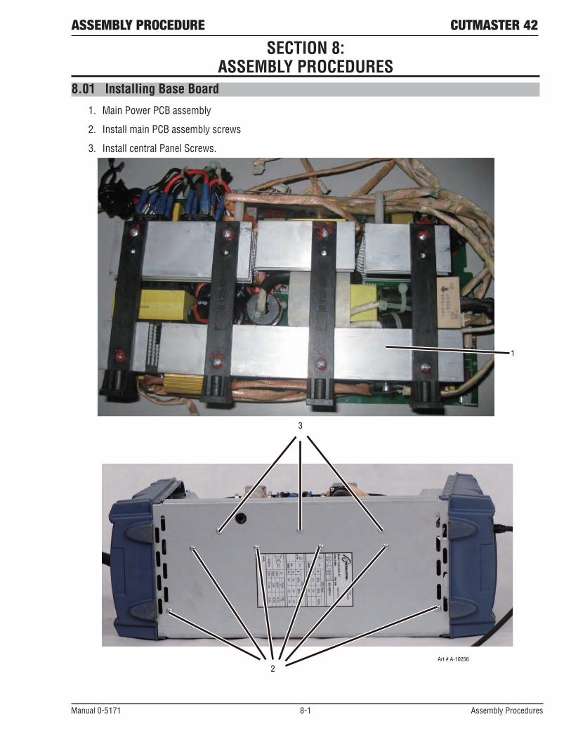
ASSEMBLY PROCEDURE CUTMASTER 42
Manual 0-5171 8-1 Assembly Procedures
8.01 Installing Base Board
1. Main Power PCB assembly
2. Install main PCB assembly screws
3. Install central Panel Screws.
1
3
2Art # A-10256
SECTION 8: ASSEMBLY PROCEDURES

Assembly Procedures 8-2 Manual 0-5171
CUTMASTER 42 ASSEMBLY PROCEDURES8.02 Installing Back Panel
1. Install gas inlet.
2. Install ON/OFF switch
3. Install wire cord.
4. Reconnect Input Wire on the ON/OFF switch.
5. Install fan.
6. Install ground wire.
7. Reconnect AC Input wire on Main Power PCB to power ON/OFF switch.
8. Reconnect the three screws.
9. Reconnect Rear Panel screws.
1
5
2
4
3
Art # A-10257
6
9

ASSEMBLY PROCEDURE CUTMASTER 42
Manual 0-5171 8-3 Assembly Procedures
8
Art # A-10258
7

Assembly Procedures 8-4 Manual 0-5171
CUTMASTER 42 ASSEMBLY PROCEDURES
8.03 Installing Front Panel
1. Place front panel PCB assembly into front panel. Install the nut and screw.
2. Reconnect three harnesses to control PCB.
3. Reconnect two red wires and install the screws.
4. Install the front panel screws.
42
3
Art # A-10259
1

ASSEMBLY PROCEDURE CUTMASTER 42
Manual 0-5171 8-5 Assembly Procedures
8.04 Installing Main Control Panel and Clear Cover Sheet
1. Install 4 screws.
2. Plug harness into HF/QF connector
3. Plug harness into MB connector
4. Plug harness into SOURCE&TIP connector
5. Plug harness into DRIVE connector
6. Plug harness into U-D connector
7. Plug harness into WA connector
8. Plug harness into FAN connector
9. Plug harness into TRANF-IFB connector
10. Plug harness into WV connector
11. Plug harness into D-PORT connector
12. Plug harness into OT connector
13. Plug harness into PRESSURE connector
14. Plug harness into GUN&TEST connector
15. Install clear protective sheet.

Assembly Procedures 8-6 Manual 0-5171
CUTMASTER 42 ASSEMBLY PROCEDURES
61
5 43
2
14
13
12
1110987 Art # A-10250
15 Art # A-10260

ASSEMBLY PROCEDURE CUTMASTER 42
Manual 0-5171 8-7 Assembly Procedures
J1(H
F/QF
)J2
(MB)
J3(H
FOUT
)J4
(SOU
RCE&
TIP)
J5(D
RIVE
)
J6(U
_D)
J14(
GUN&
TEST
)
J13(
PRES
SURE
)
J12(
OT)
J7(W
A)Ar
t # A
-102
46J8
(FAN
)J9
(Tra
nsf I
FB)
SW1
J10(
WV)
J11(
D_po
rt)GN
D

Assembly Procedures 8-8 Manual 0-5171
CUTMASTER 42 ASSEMBLY PROCEDURES
8.05 Installing Case1. Install Case.
2. Install Screws. Tighten screws.
Art # A-10261
1
2

REPLACEMENT PARTS CUTMASTER 42
Manual 0-5171 9-1 Replacement Parts
SECTION 9: Replacement PARTS
9.01 Introduction
A. Parts List Breakdown
The parts list provides a breakdown of all replaceable components. B. Returns
If a product must be returned for service, contact your distributor. Materials returned without proper authoriza-tion will not be accepted.C. Ordering Information
Order replacement parts by catalog number and complete description of the part or assembly, as listed in the parts list for each type item. Also include the model and serial number of the torch. Address all inquiries to your authorized distributor.

CUTMASTER 42 REPLACEMENT PARTS
Replacement Parts 9-2 Manual 0-5171
9.02 Power Supply Replacement Parts Item # Qty Description Catalog # 1 1 Control PCB assembly 9-0077 2 1 Front Control PCB assembly 9-0076 3 1 Main PCB assembly 9-0079 4 1 Regulator 9-0081 5 1 Solenoid assembly 9-0082 6 1 Pressure Switch 9-0075 7 1 Front Panel with Label 9-0071 8 1 Rear Panel with Label 9-0072 9 1 Cover with Labels 9-0080 10 1 Hall Current Sensor 9-0088 11 1 CM42CuttingControlKnob 9-0073 12 1 CM42 On/Off Switch 9-0074 13 1 ATC Connection 9-0083 14 1 Fan 9-0042 15 1 AC/DC Rectifier 9-0049 16 1 Power Cord 9-0025 17 1 CM42 Carry Case (not shown) 9-0084 18 1 Gloves (not shown) 9-0086 19 1 Glasses (not shown) 9-0087 20 1 120VAC Adapter, 15A W4014000
Art # A-09387_AF
9
5
1
2
11
13
7
3
15
10
1420
8
12
6
4
16

REPLACEMENT PARTS CUTMASTER 42
Manual 0-5171 9-3 Replacement Parts
9.03 SL40 Torch Replacement Parts Item # Qty. Description Catalog # 1 1 SL40 Torch w/15ft(4.6m) leads, (not shown) 7-0040 2 1 HandleKit(notshown) 9-0089 3 1 Microswitch 9-7031 4 2 Electrode 9-0096 5 1 Start Cartridge 9-0097 6 2 Tip, 40A Standoff 9-0094 7 2 , Tip, 40A Drag 9-0093 2 Tip, 20A Drag 9-0091 8 1 Shield Cup 9-0098
Art # A-11752
5
67
8
43

CUTMASTER 42 REPLACEMENT PARTS
Replacement Parts 9-4 Manual 0-5171
9.04 Optional Accessories
Description Cat. No.Standoff Guide for SL40 9-0090Cutting Guide Bushing, accommodating the use of the SL40 with the cutting guides 7-2915
TorchCuttingGuides/GuidesKitsincludingCarryingCase,Radius/RollerKit(7-7501),CircleCuttingGuide(7-3291), Magnetic Pivot, Suction Pivot
7-8910
CircleCuttingGuideKit, 7-3291Radius/RollerCuttingGuideKit 7-7501Filter Body, single stage air filter 7-7507Hose, single stage air filter 9-7742Filter Element, single stage air filter 9-7741Two Stage Air Filter 9-9387First Stage Element, two stage filter 9-1021Second Stage Element, two stage filter 9-1022

APPENDIx CUTMASTER 42
Manual 0-5171 A-1 Appendix
APPENDIX 1: SL40 TORCH PIN-OUT DIAGRAM
A. Hand Torch Pin-Out Diagram
12
34
56
78
5
678
12
34
PilotPilot
6 - Open
7 - Open
8 - Open
5 - Open
Negative / Plasma
6 - Open
7 - Open
5 - Open
2 - Torch Jumper input
3 - Torch/PIP switch input
4 - Torch/PIP switch input
1 - Torch Jumper input
4 - Green / Torch/PIP switches
1&2- Shorted Jumper
3 - Yellow / Torch/PIP switches
Negative / Plasma
Cutmaster 42 Female Torch ReceptacleFront View
8 - Ground
ATC Male ConnectorFront View
Art # A-11809

THE AMERICASDenton, TX USAU.S. Customer CarePh: 1-800-426-1888 (tollfree)Fax: 1-800-535-0557 (tollfree)International Customer CarePh: 1-940-381-1212Fax: 1-940-483-8178
Miami, FL USASales Office, Latin America Ph: 1-954-727-8371Fax: 1-954-727-8376
Oakville, Ontario, CanadaCanada Customer CarePh: 1-905-827-4515Fax: 1-800-588-1714 (tollfree)
EUROPEChorley, United KingdomCustomer CarePh: +44 1257-261755Fax: +44 1257-224800
Milan, ItalyCustomer CarePh: +39 0236546801Fax: +39 0236546840
ASIA/PACIFICCikarang, IndonesiaCustomer CarePh: 6221-8990-6095Fax: 6221-8990-6096
Rawang, MalaysiaCustomer CarePh: +603 6092-2988Fax: +603 6092-1085
Melbourne, AustraliaAustralia Customer CarePh: 1300-654-674 (tollfree)Ph: 61-3-9474-7400 Fax: 61-3-9474-7391InternationalPh: 61-3-9474-7508Fax: 61-3-9474-7488
Shanghai, ChinaSales OfficePh: +86 21-64072626Fax: +86 21-64483032SingaporeSales OfficePh: +65 6832-8066Fax: +65 6763-5812
Form No. 0-5171 (01/28/13) © 2012 Victor Technologies International, Inc. www.victortechnologies.com Printed in China
U.S. Customer Care: 800-426-1888 • Canada Customer Care: 905-827-4515 • International Customer Care: 940-381-1212
I N N O V A T I O N T O S H A P E T H E W O R L D ™T E C H N O L O G I E S ™