thermal hydraulics of nuclear micro-reactors and msr 905
TRANSCRIPT
Assessment of the Thermal-Structural Characteristics of Core Components in a
Preconceptual Design of the Transformational Challenge Reactor
Casey J. Jesse*, James W. Sterbentz*, Benjamin R. Betzler†
*Idaho National Laboratory, Idaho Falls, ID 83415, [email protected], [email protected]†Oak Ridge National Laboratory, Oak Ridge, TN 37831, [email protected]
INTRODUCTION
The Transformational Challenge Reactor (TCR) is a
megawatt-scale microreactor currently being designed at
Oak Ridge National Laboratory (ORNL). The TCR will
demonstrate the feasibility of designing, building, and
operating a micro-reactor using advanced manufacturing
technologies with conventionally manufactured fuel. This
paper focuses on evaluating the thermal and structural characteristics of the components within a preconceptual
core design of the TCR. To accomplish this a conjugate heat
transfer model was developed with the computational fluid
dynamics (CFD) code, Star-CCM+ [1] and a thermal-
mechanical model was developed with the finite element
analysis (FEA) code, Abaqus [2].
MODEL DESCRIPTION
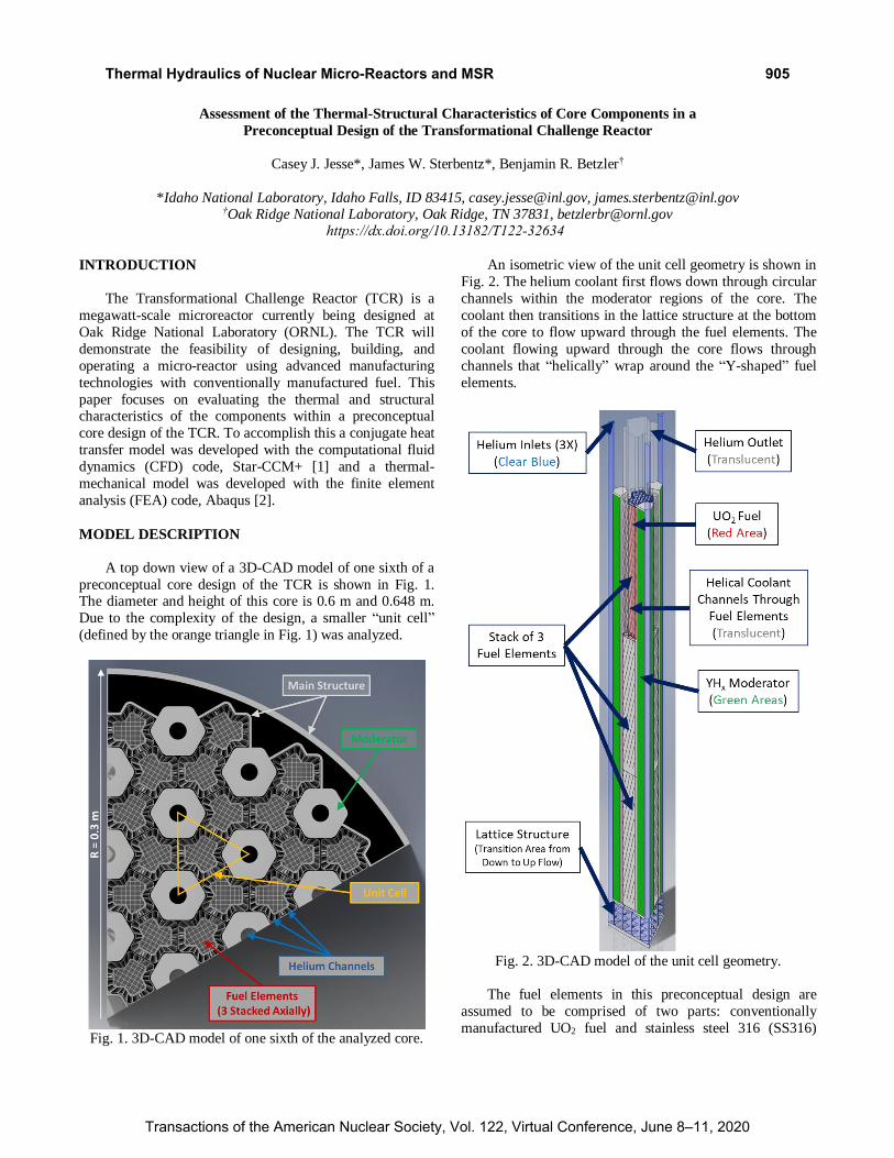
A top down view of a 3D-CAD model of one sixth of a
preconceptual core design of the TCR is shown in Fig. 1. The diameter and height of this core is 0.6 m and 0.648 m.
Due to the complexity of the design, a smaller “unit cell”
(defined by the orange triangle in Fig. 1) was analyzed.
Fig. 1. 3D-CAD model of one sixth of the analyzed core.
An isometric view of the unit cell geometry is shown in
Fig. 2. The helium coolant first flows down through circular
channels within the moderator regions of the core. The
coolant then transitions in the lattice structure at the bottom
of the core to flow upward through the fuel elements. The
coolant flowing upward through the core flows through
channels that “helically” wrap around the “Y-shaped” fuel
elements.
Fig. 2. 3D-CAD model of the unit cell geometry.
The fuel elements in this preconceptual design are
assumed to be comprised of two parts: conventionally
manufactured UO2 fuel and stainless steel 316 (SS316)
https://dx.doi.org/10.13182/T122-32634
Thermal Hydraulics of Nuclear Micro-Reactors and MSR
Transactions of the American Nuclear Society, Vol. 122, Virtual Conference, June 8–11, 2020
905
which surrounds and contains the UO2 fuel. The focus of
this analysis was on the thermal-hydraulic and thermal-
mechanical characteristics of the fuel elements. In
particular, the top fuel element in the unit cell’s fuel element
stack is scrutinized the most since it reaches the highest
temperature of the three fuel elements.
NUMERICAL MODEL DEVELOPMENT
A conjugate heat transfer model was developed in Star-
CCM+ due to the limitations of modeling fluid flow in
Abaqus. The coolant temperature and heat transfer
coefficients calculated in Star-CCM+ were subsequently
used in the Abaqus model to calculate the thermal stresses
that develop in the fuel elements. All material properties in
Abaqus and Star-CCM+ were defined to vary with
temperature.
The flow was assumed to be turbulent and pressurized to 8 MPa. The Reynolds-Averaged Navier-Stokes (RANS)
Standard k-Omega model was utilized to model the
turbulent flow. The thermal power of the reactor was varied
from 1 to 4 MW. An average heat generation rate was used
in the UO2 fuel and was assumed to be uniformly generated
throughout its volume, i.e. no axial variation was
considered. The temperature and mass flow rate at the inlet
of the model was set to 250°C and 0.008 kg/s (~0.86 kg/s
for the entire core) at a power level of 1 MW. The mass
flow rate was linearly increased with increasing power to
maintain a consistent coolant outlet temperature of about 748 K (475°C).
An Abaqus model was developed to evaluate the
thermal stresses in the fuel elements. As aforementioned the
coolant temperatures and heat transfer coefficients from the
Star-CCM+ model were applied to the coolant surfaces in
the Abaqus model. They were defined to vary axially
(direction of the coolant flow).
The first step in the Abaqus analysis was a steady-state
heat transfer calculation. This heat transfer step was
followed by a static stress analysis to evaluate the thermal
stresses that develop due to variations in temperature. To
hold the element in place spatially during the stress analysis, the bottom surface of the element was fixed in the axial
direction. Elastic properties were assumed for the materials.
RESULTS
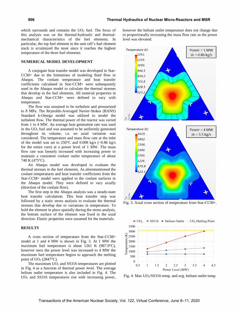
A cross section of temperature from the Star-CCM+
model at 1 and 4 MW is shown in Fig. 3. At 1 MW the
maximum fuel temperature is about 1261 K (987.9°C),
however once the power level was increased to 4 MW the
maximum fuel temperature begins to approach the melting
point of UO2 (2847°C). The maximum UO2 and SS316 temperatures are plotted
in Fig. 4 as a function of thermal power level. The average
helium outlet temperature is also included in Fig. 4. The
UO2 and SS316 temperatures rise with increasing power,
however the helium outlet temperature does not change due
to proportionally increasing the mass flow rate as the power
level was elevated.
Fig. 3. Axial cross section of temperature from Star-CCM+.
Fig. 4. Max UO2/SS316 temp. and avg. helium outlet temp.
Thermal Hydraulics of Nuclear Micro-Reactors and MSR
Transactions of the American Nuclear Society, Vol. 122, Virtual Conference, June 8–11, 2020
906

The temperature of the SS316 in the fuel element stack
from the thermal model in Star-CCM+ and Abaqus are
shown on the top and bottom of Fig. 5, respectively. The
results from both codes show similar results with the
Abaqus model predicting a slightly higher maximum
temperature of 974.2 K (701.1°C).
Fig. 5. Comparing results from Star-CCM+ and Abaqus.
The von Mises stresses from the static stress model in
Abaqus are shown at the bottom of Fig. 6 with the
corresponding temperatures at the top of Fig. 6. The stresses
are plotted with the maximum color bar limit at 700 MPa
since the locations of the stresses at 948 MPa are at sharp
reentrant corners where numerical singularities occur. At these locations the stress never converges to a value and will
infinitely increase as the mesh is refined. Therefore, the
upper limit on the color bar was set to 700 MPa to more
clearly show the high stresses away from these corners.
Overall the stresses throughout the SS316 are about 200 to
300 MPa with some areas reaching 600 MPa, which is very
high for SS316 at these temperatures.
Fig. 6. Temperature and von Mises stresses in the SS316.
Thermal Hydraulics of Nuclear Micro-Reactors and MSR
Transactions of the American Nuclear Society, Vol. 122, Virtual Conference, June 8–11, 2020
907
CONCLUSIONS
The Star-CCM+ and Abaqus codes were utilized to
calculate temperature, stress, and thermal expansion
responses of the fuel elements in this preconceptual reactor
design of the TCR. The total core power level was varied from 1 to 4 MW. The Star-CCM+ model was used to
evaluate the relatively complicated helium coolant flow
while the Abaqus model was utilized to assess thermal
stresses that are produced by temperature variations in the
fuel elements. The Star-CCM+ and Abaqus temperature
results were in excellent agreement with each other, thereby
providing some level of model verification.
Stress limits for SS316 are provided up to a maximum
temperature of 1098 K (825°C) in the ASME code [3]. This
temperature limit is surpassed in the top fuel element of the
Star-CCM+ unit cell model at a power level of 2 MW as
shown in TABLE I. Therefore, thermal stresses were evaluated only at the 1 MW core power level in Abaqus.
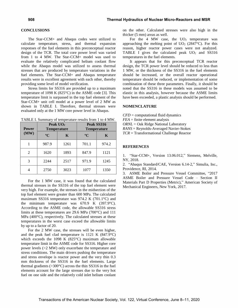
TABLE I. Summary of temperature results from 1 to 4 MW.
Power
(MW)
Peak UO2
Temperature
Peak SS316
Temperature
ºC K ºC K
1 987.9 1261 701.1 974.2
2 1620 1893 847.9 1121
3 2244 2517 971.9 1245
4 2750 3023 1077 1350
For the 1 MW case, it was found that the calculated
thermal stresses in the SS316 of the top fuel element were
very high. For example, the stresses in the midsection of the
top fuel element were greater than 600 MPa. The calculated
maximum SS316 temperature was 974.2 K (701.1°C) and
the minimum temperature was 670.9 K (397.9°C).
According to the ASME code, the allowable SS316 stress
limits at these temperatures are 29.6 MPa (700°C) and 111
MPa (400°C), respectively. The calculated stresses at these
temperatures in the worst case exceed the allowable limits
by up to a factor of 20.
For the 2 MW case, the stresses will be even higher, and the peak fuel clad temperature is 1121 K (847.9°C)
which exceeds the 1098 K (825°C) maximum allowable
temperature limit in the ASME code for SS316. Higher core
power levels (>2 MW) only exacerbate the temperature and
stress conditions. The main drivers pushing the temperature
and stress envelope is reactor power and the very thin 0.3
mm thickness of the SS316 in the fuel elements. Large
thermal gradients (>300°C) across the thin SS316 in the fuel
elements account for the large stresses due to the very hot
fuel on one side and the relatively cold inlet helium coolant
on the other. Calculated stresses were also high in the
thicker (5 mm) areas as well.
For the 4 MW case, the UO2 temperature was
approaching the melting point of UO2 (2847°C). For this
reason, higher reactor power cases were not analyzed.
TABLE I gives the calculated peak UO2 and SS316 temperatures in the fuel elements.
It appears that for this preconceptual TCR reactor
design, the TCR power level should be reduced to less than
1 MW, or the thickness of the SS316 in the fuel elements
should be increased, or the overall reactor operational
temperature should be reduced, or implementation of some
combination of these three parameters. Finally, it should be
noted that the SS316 in these models was assumed to be
elastic in this analysis, however because the ASME limits
have been exceeded, a plastic analysis should be performed.
NOMENCLATURE
CFD = computational fluid dynamics
FEA = finite element analysis
ORNL = Oak Ridge National Laboratory
RANS = Reynolds-Averaged Navier-Stokes
TCR = Transformational Challenge Reactor
REFERENCES
1. “Star-CCM+, Version 13.06.012,” Siemens, Melville, NY, 2018.
2. “Abaqus Standard/CAE, Version 6.14-2,” Simulia, Inc.,
Providence, RI, 2014.
3. ASME Boiler and Pressure Vessel Committee, “2017
ASME Boiler and Pressure Vessel Code – Section II
Materials Part D Properties (Metric),” American Society of
Mechanical Engineers, New York, 2017.
Thermal Hydraulics of Nuclear Micro-Reactors and MSR
Transactions of the American Nuclear Society, Vol. 122, Virtual Conference, June 8–11, 2020
908