thermal-magnetic miniature circuit breaker 4230-t thermal-magnetic miniature circuit breaker...
TRANSCRIPT
www.e-t-a.de 1
Thermal-magnetic Miniature Circuit Breaker 4230-T...
1638
1
Rupture capacity
to IEC/EN 60947-2 (Ics) AC 7,500 A / DC 10,000 A
to IEC/EN 60947-2 (Icu)
AC/DC 10,000 A
to UL 489 AC/DC 10,000 A
Insulation coordination 6 kV/3 (reinforced insulation at operating area)
Degree of protection IP20
Vibration (sinusoidal) test to IEC 60068-2-6, test Fc
± 0.38 mm (10–57 Hz), 5 g (57–500 Hz) 10 frequency cycles per axis
Shock, test to IEC 60068-2-27, test Ea
30 g (11 ms)
Corrosion, test to IEC 60068-2-11, test Ka
96 hrs in 5% salt mist
Humidity, test to IEC 60068-2-78, test Cab
48 hours at 95% RH, temperature +40°C
Terminals screw terminals
Vertical connection possible by means of busbars
Tightening torque 2 Nm max.
Cable cross section ≤35 mm²
Ambient temperature: -35°C...+ 70°C
Mounting rail mounting
Mass approx. 116 g per pole (EN 60947-2/UL 1077) approx. 131 g per pole (UL 489)
Description
Typical applications
Technical DataTechnical Data
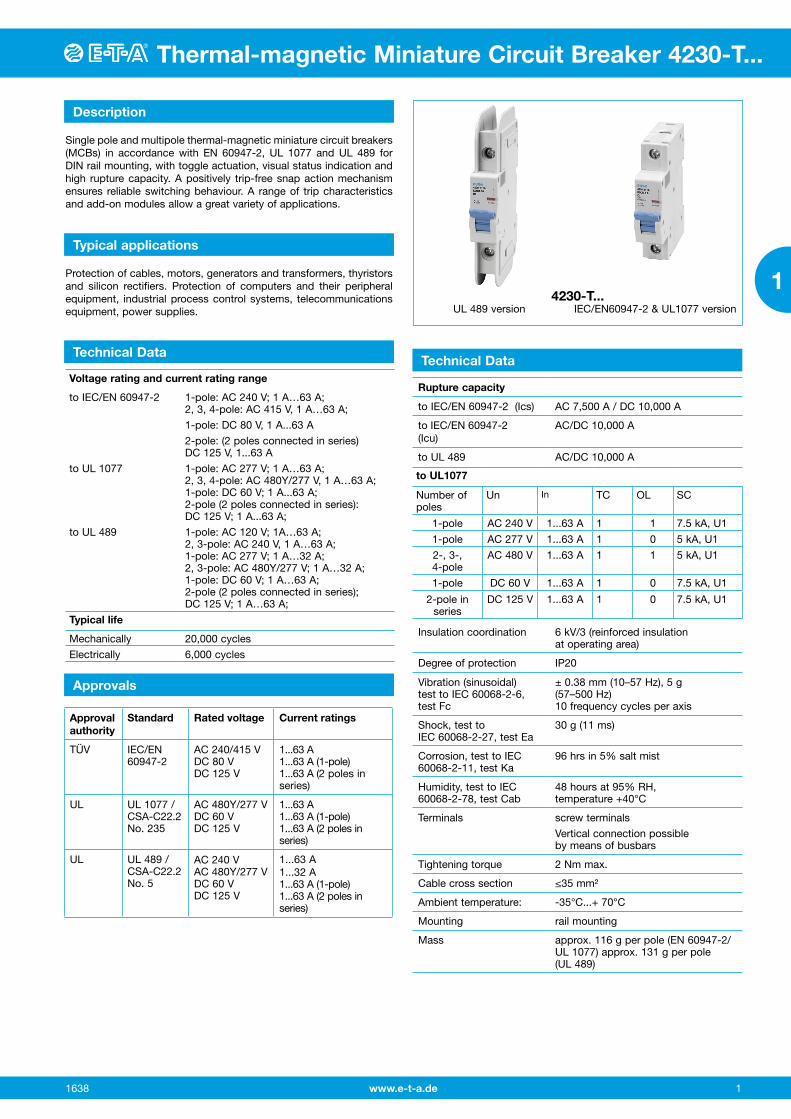
Single pole and multipole thermal-magnetic miniature circuit breakers (MCBs) in accordance with EN 60947-2, UL 1077 and UL 489 for DIN rail mounting, with toggle actuation, visual status indication and high rupture capacity. A positively trip-free snap action mechanism ensures reliable switching behaviour. A range of trip characteristics and add-on modules allow a great variety of applications.
Protection of cables, motors, generators and transformers, thyristors and silicon rectifiers. Protection of computers and their peripheral equipment, industrial process control systems, telecommunications equipment, power supplies.
4230-T... UL 489 version IEC/EN60947-2 & UL1077 version
Voltage rating and current rating range
to IEC/EN 60947-2 1-pole: AC 240 V; 1 A…63 A; 2, 3, 4-pole: AC 415 V, 1 A…63 A;
1-pole: DC 80 V, 1 A...63 A
2-pole: (2 poles connected in series) DC 125 V, 1...63 A
to UL 1077 1-pole: AC 277 V; 1 A…63 A; 2, 3, 4-pole: AC 480Y/277 V, 1 A…63 A; 1-pole: DC 60 V; 1 A...63 A; 2-pole (2 poles connected in series): DC 125 V; 1 A...63 A;
to UL 489 1-pole: AC 120 V; 1A…63 A; 2, 3-pole: AC 240 V, 1 A…63 A; 1-pole: AC 277 V; 1 A…32 A; 2, 3-pole: AC 480Y/277 V; 1 A…32 A; 1-pole: DC 60 V; 1 A…63 A; 2-pole (2 poles connected in series); DC 125 V; 1 A…63 A;
Typical life
Mechanically 20,000 cycles
Electrically 6,000 cycles
to UL1077
Number of poles
Un In TC OL SC
1-pole AC 240 V 1...63 A 1 1 7.5 kA, U1
1-pole AC 277 V 1...63 A 1 0 5 kA, U1
2-, 3-, 4-pole
AC 480 V 1...63 A 1 1 5 kA, U1
1-pole DC 60 V 1...63 A 1 0 7.5 kA, U1
2-pole in series
DC 125 V 1...63 A 1 0 7.5 kA, U1
Approvals
Approval authority
Standard Rated voltage Current ratings
TÜV IEC/EN 60947-2
AC 240/415 V DC 80 V DC 125 V
1...63 A 1...63 A (1-pole) 1...63 A (2 poles in series)
UL UL 1077 / CSA-C22.2 No. 235
AC 480Y/277 V DC 60 V DC 125 V
1...63 A 1...63 A (1-pole) 1...63 A (2 poles in series)
UL UL 489 / CSA-C22.2 No. 5
AC 240 V AC 480Y/277 V DC 60 V DC 125 V
1...63 A 1...32 A 1...63 A (1-pole) 1...63 A (2 poles in series)
www.e-t-a.de 2
Thermal-magnetic Miniature Circuit Breaker 4230-T...
1638
1
Order numbering code Type No.4230 single and multipole thermal-magnetic high performance circuit breaker Mounting T1 rail mounting Number of poles 1 single pole protected 2 double pole protected 3 three pole protected 4 four pole protected* Accessories 0 without terminals K0 screw terminals Characteristic curve B: thermal 1.05 - 1.30 x IN; magnetic 3.2 - 4.8 x IN C: thermal 1.05 - 1.30 x IN; magnetic 6.4 - 9.6 x IN D: thermal 1.05 - 1.30 x IN; magnetic 9.6 - 14.4 x IN Approvals E IEC/EN 60947-2 (TÜV) / UL 1077 U UL 489 (only 1-, 2- & 3-pole) /
IEC/EN 60947-2 (TÜV) Current ratings: 1, 2, 3, 4, 5, 6, 7, 8, 10, 12, 13, 15, 16, 20, 25,
30, 32, 35, 40, 50, 60, 63 A 4230 - T1 1 0 - K0 C E - 10 A ordering example* not for UL 489
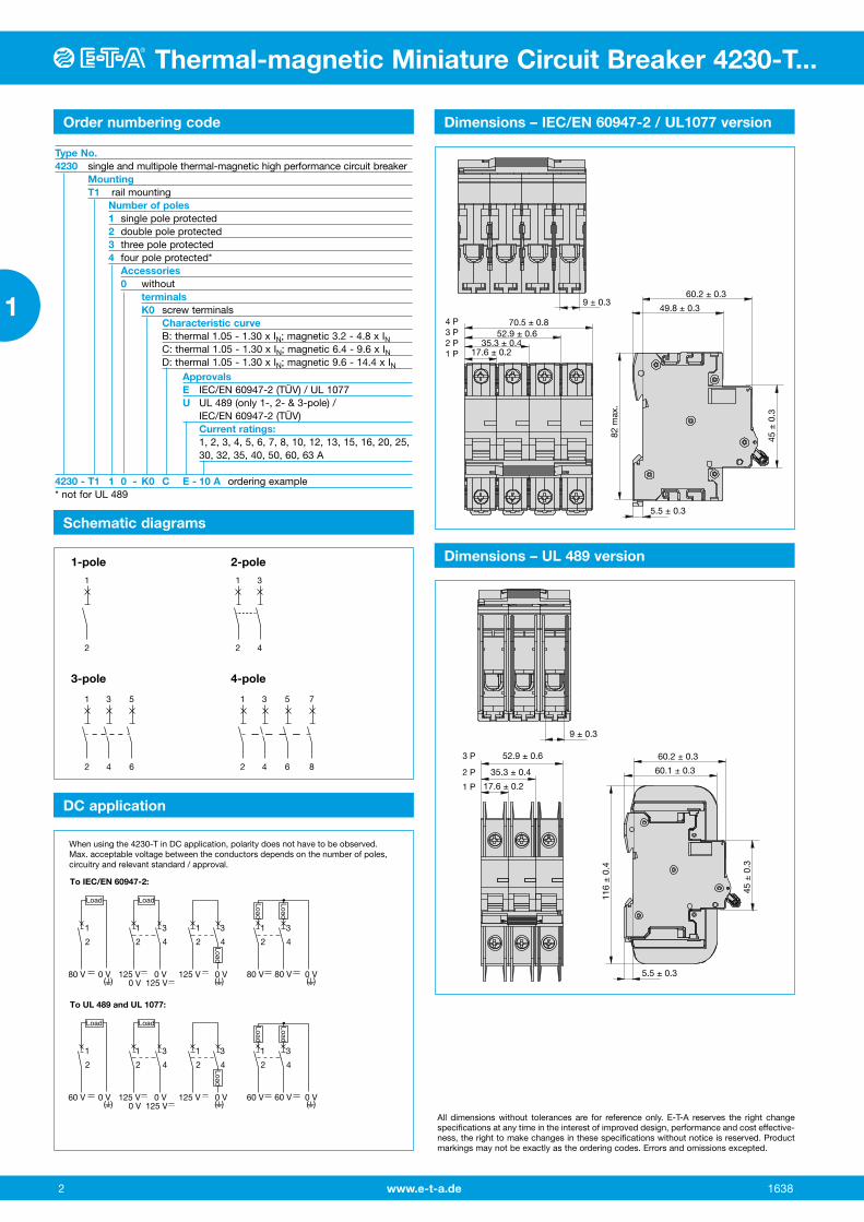
Dimensions – IEC/EN 60947-2 / UL1077 version
60.2 ± 0.3
70.5 ± 0.852.9 ± 0.6
35.3 ± 0.417.6 ± 0.21 P
2 P3 P4 P
49.8 ± 0.3
5.5 ± 0.3
9 ± 0.3
82 m
ax.
45 ±
0.3
Dimensions – UL 489 version
60.2 ± 0.352.9 ± 0.6
60.1 ± 0.3
5.5 ± 0.3
9 ± 0.3
116
± 0
.4
45 ±
0.3
35.3 ± 0.4
17.6 ± 0.21 P
2 P
3 P
All dimensions without tolerances are for reference only. E-T-A reserves the right change specifications at any time in the interest of improved design, performance and cost effective-ness, the right to make changes in these specifications without notice is reserved. Product markings may not be exactly as the ordering codes. Errors and omissions excepted.
Schematic diagrams
1
2
3-pole 4-pole
1-pole 2-pole
1
2
3
4
1
2
3
4
5
6
1
2
3
4
5
6
7
8
DC application
1
2
80 V 0 V 125 V 0 V0 V 125 V
125 V 0 V 80 V 80 V 0 V
1
2
3
4
3
4
3
4
1
2
1
2
When using the 4230-T in DC application, polarity does not have to be observed.Max. acceptable voltage between the conductors depends on the number of poles, circuitry and relevant standard / approval.
To IEC/EN 60947-2:
( ) ( ) ( )
Load Load
Load
Load
Load
1
2
60 V 0 V 125 V 0 V0 V 125 V
125 V 0 V 60 V 60 V 0 V
1
2
3
4
3
4
3
4
1
2
1
2
To UL 489 and UL 1077:
( ) ( ) ( )
Load Load
Load
Load
Load
Hinweis: Spannungen zwischen Leiter und Erde sind abhängig von der Art der Erdung (symmetrisch, unsymmetrisch).
www.e-t-a.de 3
Thermal-magnetic Miniature Circuit Breaker 4230-T...
1638
1
Thermal-magnetic Miniature Circuit Breaker 4230-T...
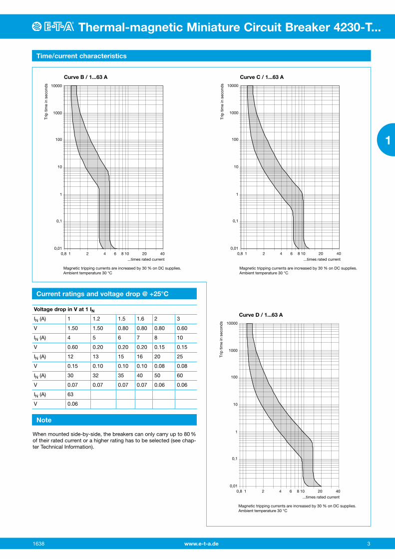
Current ratings and voltage drop @ +25°C
Time/current characteristics
Voltage drop in V at 1 IN
IN (A) 1 1.2 1.5 1.6 2 3
V 1.50 1.50 0.80 0.80 0.80 0.60
IN (A) 4 5 6 7 8 10
V 0.60 0.20 0.20 0.20 0.15 0.15
IN (A) 12 13 15 16 20 25
V 0.15 0.10 0.10 0.10 0.08 0.08
IN (A) 30 32 35 40 50 60
V 0.07 0.07 0.07 0.07 0.06 0.06
IN (A) 63
V 0.06
10000
1000
100
10
1
0,1
0,010,8 1 2 4 6 8 10 20 40
Curve D / 1...63 A
...times rated current
Magnetic tripping currents are increased by 30 % on DC supplies.Ambient temperature 30 °C
Trip
tim
e in
sec
ond
s
10000
1000
100
10
1
0,1
0,010,8 1 2 4 6 8 10 20 40
Curve B / 1...63 A
...times rated current
Trip
tim
e in
sec
ond
s
Magnetic tripping currents are increased by 30 % on DC supplies.Ambient temperature 30 °C
...times rated current
Curve C / 1...63 A
10000
1000
100
10
1
0,1
0,010,8 1 2 4 6 8 10 20 40
Trip
tim
e in
sec
ond
s
Magnetic tripping currents are increased by 30 % on DC supplies.Ambient temperature 30 °C
Note
When mounted side-by-side, the breakers can only carry up to 80 % of their rated current or a higher rating has to be selected (see chap-ter Technical Information).
www.e-t-a.de 4
Thermal-magnetic Miniature Circuit Breaker 4230-T...
1638
1
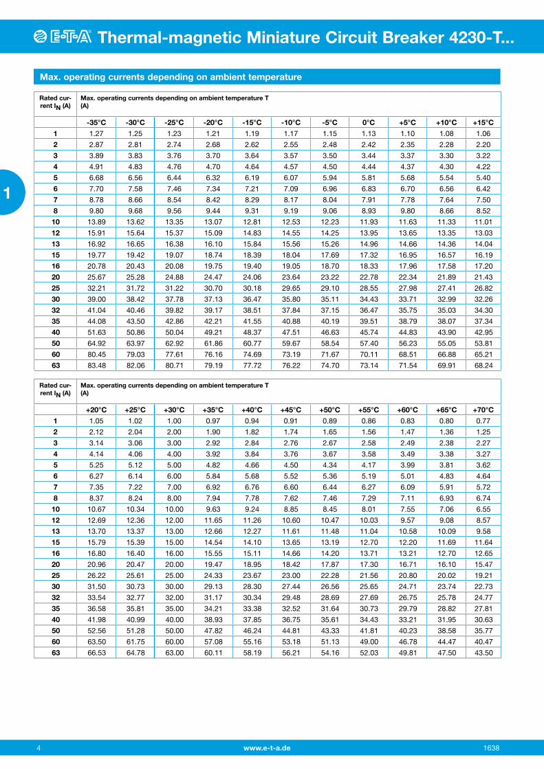
Max. operating currents depending on ambient temperature
Rated cur-rent IN (A)
Max. operating currents depending on ambient temperature T (A)
-35°C -30°C -25°C -20°C -15°C -10°C -5°C 0°C +5°C +10°C +15°C
1 1.27 1.25 1.23 1.21 1.19 1.17 1.15 1.13 1.10 1.08 1.06
2 2.87 2.81 2.74 2.68 2.62 2.55 2.48 2.42 2.35 2.28 2.20
3 3.89 3.83 3.76 3.70 3.64 3.57 3.50 3.44 3.37 3.30 3.22
4 4.91 4.83 4.76 4.70 4.64 4.57 4.50 4.44 4.37 4.30 4.22
5 6.68 6.56 6.44 6.32 6.19 6.07 5.94 5.81 5.68 5.54 5.40
6 7.70 7.58 7.46 7.34 7.21 7.09 6.96 6.83 6.70 6.56 6.42
7 8.78 8.66 8.54 8.42 8.29 8.17 8.04 7.91 7.78 7.64 7.50
8 9.80 9.68 9.56 9.44 9.31 9.19 9.06 8.93 9.80 8.66 8.52
10 13.89 13.62 13.35 13.07 12.81 12.53 12.23 11.93 11.63 11.33 11.01
12 15.91 15.64 15.37 15.09 14.83 14.55 14.25 13.95 13.65 13.35 13.03
13 16.92 16.65 16.38 16.10 15.84 15.56 15.26 14.96 14.66 14.36 14.04
15 19.77 19.42 19.07 18.74 18.39 18.04 17.69 17.32 16.95 16.57 16.19
16 20.78 20.43 20.08 19.75 19.40 19.05 18.70 18.33 17.96 17.58 17.20
20 25.67 25.28 24.88 24.47 24.06 23.64 23.22 22.78 22.34 21.89 21.43
25 32.21 31.72 31.22 30.70 30.18 29.65 29.10 28.55 27.98 27.41 26.82
30 39.00 38.42 37.78 37.13 36.47 35.80 35.11 34.43 33.71 32.99 32.26
32 41.04 40.46 39.82 39.17 38.51 37.84 37.15 36.47 35.75 35.03 34.30
35 44.08 43.50 42.86 42.21 41.55 40.88 40.19 39.51 38.79 38.07 37.34
40 51.63 50.86 50.04 49.21 48.37 47.51 46.63 45.74 44.83 43.90 42.95
50 64.92 63.97 62.92 61.86 60.77 59.67 58.54 57.40 56.23 55.05 53.81
60 80.45 79.03 77.61 76.16 74.69 73.19 71.67 70.11 68.51 66.88 65.21
63 83.48 82.06 80.71 79.19 77.72 76.22 74.70 73.14 71.54 69.91 68.24
Rated cur-rent IN (A)
Max. operating currents depending on ambient temperature T (A)
+20°C +25°C +30°C +35°C +40°C +45°C +50°C +55°C +60°C +65°C +70°C
1 1.05 1.02 1.00 0.97 0.94 0.91 0.89 0.86 0.83 0.80 0.77
2 2.12 2.04 2.00 1.90 1.82 1.74 1.65 1.56 1.47 1.36 1.25
3 3.14 3.06 3.00 2.92 2.84 2.76 2.67 2.58 2.49 2.38 2.27
4 4.14 4.06 4.00 3.92 3.84 3.76 3.67 3.58 3.49 3.38 3.27
5 5.25 5.12 5.00 4.82 4.66 4.50 4.34 4.17 3.99 3.81 3.62
6 6.27 6.14 6.00 5.84 5.68 5.52 5.36 5.19 5.01 4.83 4.64
7 7.35 7.22 7.00 6.92 6.76 6.60 6.44 6.27 6.09 5.91 5.72
8 8.37 8.24 8.00 7.94 7.78 7.62 7.46 7.29 7.11 6.93 6.74
10 10.67 10.34 10.00 9.63 9.24 8.85 8.45 8.01 7.55 7.06 6.55
12 12.69 12.36 12.00 11.65 11.26 10.60 10.47 10.03 9.57 9.08 8.57
13 13.70 13.37 13.00 12.66 12.27 11.61 11.48 11.04 10.58 10.09 9.58
15 15.79 15.39 15.00 14.54 14.10 13.65 13.19 12.70 12.20 11.69 11.64
16 16.80 16.40 16.00 15.55 15.11 14.66 14.20 13.71 13.21 12.70 12.65
20 20.96 20.47 20.00 19.47 18.95 18.42 17.87 17.30 16.71 16.10 15.47
25 26.22 25.61 25.00 24.33 23.67 23.00 22.28 21.56 20.80 20.02 19.21
30 31.50 30.73 30.00 29.13 28.30 27.44 26.56 25.65 24.71 23.74 22.73
32 33.54 32.77 32.00 31.17 30.34 29.48 28.69 27.69 26.75 25.78 24.77
35 36.58 35.81 35.00 34.21 33.38 32.52 31.64 30.73 29.79 28.82 27.81
40 41.98 40.99 40.00 38.93 37.85 36.75 35.61 34.43 33.21 31.95 30.63
50 52.56 51.28 50.00 47.82 46.24 44.81 43.33 41.81 40.23 38.58 35.77
60 63.50 61.75 60.00 57.08 55.16 53.18 51.13 49.00 46.78 44.47 40.47
63 66.53 64.78 63.00 60.11 58.19 56.21 54.16 52.03 49.81 47.50 43.50
www.e-t-a.de 5
Auxiliary contact module X4230-S for circuit breaker type 4230-T...
1638
1
Thermal-magnetic Miniature Circuit Breaker 4230-T...
Description
Mounting instructions
Typical applications
Mounting
Add-on module for circuit breaker type 4230-T. The auxiliary switch has a change-over contact as signal contact and is operated with actuation of the MCB.
Mounting to MCB to UL 489
The following steps have to be carried out for mounting the auxiliary contact module:- Remove the left-side covers for the latching notches of the auxiliary
contact module on both isolation pieces of the MCB, e.g. by means of a screw driver
- Pull off the isolation pieces from the MCB to the front- Remove blanking plug on MCB to open left-side holes for latching
notches of auxiliary switch- Re-insert isolation pieces onto MCB- Pull off left-side adhesive cover and carefully remove the perforated
cover below
Caution: the MCB to UL489 must only be operated with the insulation pieces fitted.
Status monitoring of MCB and/or the connected loads.
The add-on module is mounted on the left side of the MCB (seen from the front). For mounting, the MCB has to be in the OFF position.
Order numbering code Type No.X4230 Add-on module for type 4230-T Module type S aux. contact switch Style 0 change-over contact Terminals 1 screw terminals Key for nominal output A (to IEC/EN 60947-5-1) AC voltage DC voltage Rated Rated Rated Rated voltage current voltage current 240 V 6 A 24 V 6 A 415 V 3 A 48 V 2 A 130 V 1 A B (to UL 489) 12...240 V 6 A 12...24 V 6 A 277 V 3 A 48 V 3 A 110...220 V 1,5 A Delivery condition: L supplied separately, has to be mounted
by the user X4230- S 0 1 A L ordering example
Mounting principle
Approvals
Schematic diagrams
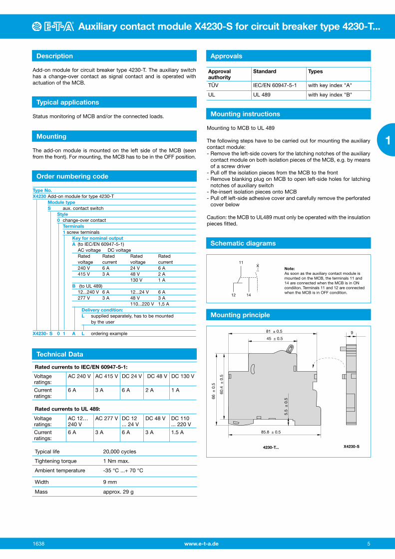
11
12 14
Note: As soon as the auxiliary contact module is mounted on the MCB, the terminals 11 and 14 are connected when the MCB is in ON condiiton. Terminals 11 and 12 are connected when the MCB is in OFF condition.
81 ± 0.5
45 ± 0.5
85.8 ± 0.5
9
66 ±
0.5
60.4
± 0
.5
5.5
± 0
.5
4230-T... X4230-S
Rated currents to IEC/EN 60947-5-1:
Rated currents to UL 489:
Typical life 20,000 cycles
Tightening torque 1 Nm max.
Ambient temperature -35 °C ...+ 70 °C
Width 9 mm
Mass approx. 29 g
Technical Data
Voltageratings:
AC 240 V AC 415 V DC 24 V DC 48 V DC 130 V
Current ratings:
6 A 3 A 6 A 2 A 1 A
Voltageratings:
AC 12… 240 V
AC 277 V DC 12 ... 24 V
DC 48 V DC 110 ... 220 V
Current ratings:
6 A 3 A 6 A 3 A 1.5 A
Approval authority
Standard Types
TÜV IEC/EN 60947-5-1 with key index "A"
UL UL 489 with key index "B"
www.e-t-a.de6
Fault indicator module X4230-A for circuit breaker type 4230-T...
1638
1
Description
Typical applications
Mounting
Add-on module for MCB type 4230-T. The fault indicator has a change-over contact as signal contact. There will only be a signal when the MCB tripped on grounds of a failure (overload, short circuit), but and not when the MCB was switched on or off manually.By actuating the reset lever on the front the tripping signal is acknowl-edged.
Status monitoring of MCB and/or the connected loads.
The add-on module is mounted on the left side of the MCB (seen from the front). For mounting, the MCB has to be in the OFF position.
Order numbering code Type No.X4230 Add-on module for type 4230-T Module type A Fault indicator module Style 0 change-over contact terminals 1 screw terminals Key for nominal output A (to IEC/EN 60947-5-1) AC voltage DC voltage Rated Rated Rated Rated voltage current voltage current 240 V 6 A 24 V 6 A 277 V 3 A 48 V 2 A 130 V 1 A B (to UL 489) 12...240 V 6 A 12...24 V 6 A 415 V 3 A 48 V 3 A 130 V 1.5 A Delivery condition: L supplied separately, has to be mounted by the user X4230-A 0 1 A L ordering example
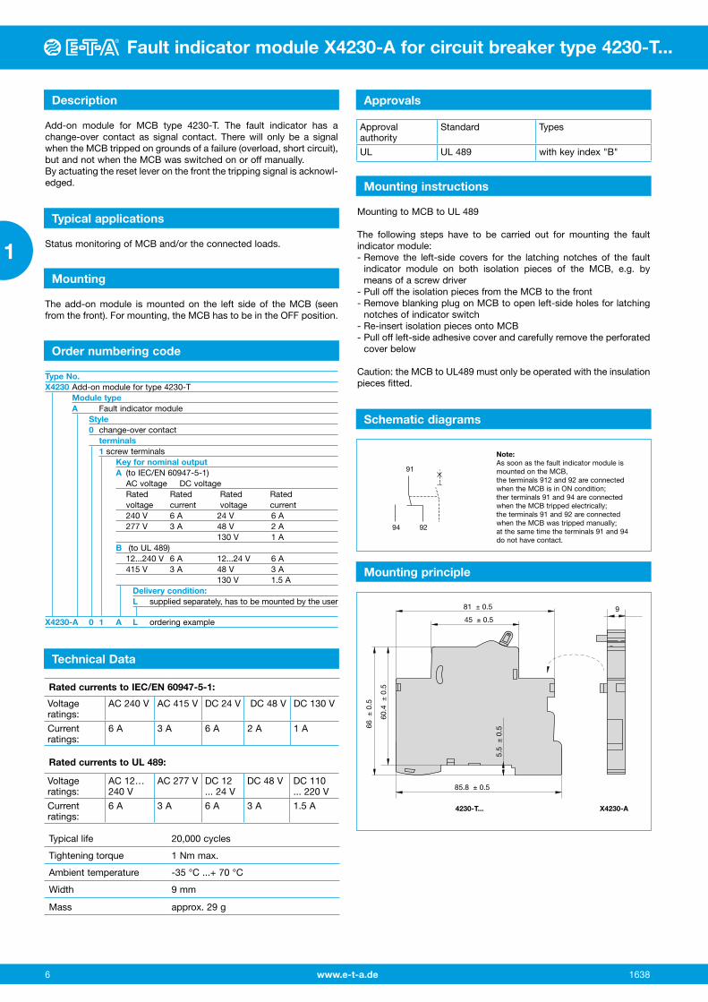
Mounting principle
Schematic diagrams
91
94 92
Note: As soon as the fault indicator module is mounted on the MCB, the terminals 912 and 92 are connected when the MCB is in ON condition; ther terminals 91 and 94 are connected when the MCB tripped electrically; the terminals 91 and 92 are connected when the MCB was tripped manually; at the same time the terminals 91 and 94 do not have contact.
81 ± 0.5
45 ± 0.5
85.8 ± 0.5
9
66 ±
0.5
60.4
± 0
.5
5.5
± 0
.5
4230-T... X4230-A
Mounting instructions
Mounting to MCB to UL 489
The following steps have to be carried out for mounting the fault indicator module:- Remove the left-side covers for the latching notches of the fault
indicator module on both isolation pieces of the MCB, e.g. by means of a screw driver
- Pull off the isolation pieces from the MCB to the front- Remove blanking plug on MCB to open left-side holes for latching
notches of indicator switch- Re-insert isolation pieces onto MCB- Pull off left-side adhesive cover and carefully remove the perforated
cover below
Caution: the MCB to UL489 must only be operated with the insulation pieces fitted.
Technical Data
Rated currents to IEC/EN 60947-5-1:
Rated currents to UL 489:
Typical life 20,000 cycles
Tightening torque 1 Nm max.
Ambient temperature -35 °C ...+ 70 °C
Width 9 mm
Mass approx. 29 g
Voltageratings:
AC 240 V AC 415 V DC 24 V DC 48 V DC 130 V
Current ratings:
6 A 3 A 6 A 2 A 1 A
Voltageratings:
AC 12… 240 V
AC 277 V DC 12 ... 24 V
DC 48 V DC 110 ... 220 V
Current ratings:
6 A 3 A 6 A 3 A 1.5 A
Approval authority
Standard Types
UL UL 489 with key index "B"
Approvals
www.e-t-a.de 7
Working current module X4230-FA for circuit breaker type 4230-T...
1638
1
Fault indicator module X4230-A for circuit breaker type 4230-T...
Description
Typical applications
Mounting
Add-on module for MCB type 4230-T. The working current module serves for remote trip of the MCB and for signalling whether the MCB was tripped electrically or manually.
Electrical remote trip of safety equipment with simultaneous monitor-ing of MCB status or its connected load.
The add-on module is mounted on the left side of the MCB (seen from the front). For mounting, the MCB has to be in the OFF position. When auxiliary contact module/fault indicator module and a working current module are mounted at the same time, the working current module always has to be mounted first.
Order numbering code Type No.X4230 Add-on module for type 4230-T Module type F Working current module Style A Magnetic coil and auxiliary switch (changeover)
physically isolated from the MCB terminals 1 screw terminals Approvals A without B UL 489 Delivery condition: L supplied separately, has to be mounted
by the user Rated voltage Approval A B AC 120 V --- UL 489 AC 240 V without UL 489 AC 277 V --- UL 489 AC 415 V without --- DC 12 V --- UL 489 DC 24 V without UL 489 DC 48 V without UL 489 DC 125 V --- UL 489
X4230- F A 1 A L - AC 240 V ordering example
Trip time < 10 ms
Typical life 20,000 cycles
Tightening torque 1 Nm max.
Ambient temperature -35 °C...+ 70 °C
Width 18 mm
Mass approx. 60 g
Technical Data
Voltage ratings AC AC 415 V AC 277 V AC 240 V AC 120 V
Min. trip voltage AC 200 V AC 160 V AC 160 V AC 80 V
Power consumption
min. response power
240 W
35 W
240 W
35 W
200 W
35 W
200 W
35 W
Rated current of auxiliary contact
3 A 3 A 6 A 6 A
Voltage ratings DC DC 125 V DC 48 V DC 24 V DC 12 V
Min. trip voltage DC 80 V DC 24 V DC 16 V DC 8 V
Power consumption
min. response power
200 W
30 VA
200 W
30 VA
200 W
30 VA
200 W
30 VA
Rated current of auxiliary contact
1.5 A 2 A 6 A 6 A
Approval authority
Standard Types
UL UL 489 Approval type "B" according to ordering number code
Approvals
Mounting instructions
Mounting to MCB to UL 489
The following steps have to be carried out for mounting the auxiliary contact module:- Remove the left-side covers for the latching notches of the working
current module on both isolation pieces of the MCB, e.g. by means of a screw driver
- Pull off the isolation pieces from the MCB to the front- Remove blanking plug on MCB to open left-side holes for latching
notches of working current module- Re-insert isolation pieces onto MCB- Pull off left-side adhesive cover and carefully remove the perforated
cover below
Caution: the MCB to UL489 must only be operated with the insulation pieces fitted.
Mounting principle
81 ± 0.5
45 ± 0.5
83 ± 0.5
18 max.
66 ±
0.5
60.1
± 0
.5
5.5
± 0
.5
4230-T... X4230-FA
Schematic diagrams
L / +N / -
11
1214
FA
C2C1

www.e-t-a.de 8
Accessories - Busbars for 4230-T...
1638
1
Busbars UL 489 to be cut to length
62.4
17.85
14.5
15x62.4 = 936
19.3
1.8
28.5
30.7
63
16.2
31.1
85
59.3
16.4
Busbars for the connection of circuit breakers type 4230-..U.. to UL 489 The busbars of 1m length can individually be cut to a suitable length for the application and isolated with end caps. Depending on the control cabinet design, the supply is by means of supply terminals without increasing the installation width or by means of a terminal block directly on the rail without increasing the installation height.
The models marked with “HS” are suitable for use with auxiliary con-tact modules with a width of 9 mm.
Busbar cross section: 18 mm².Max. busbar current Is (at 35°C): with supply at the end: 80 A with supply in the middle: 160 AShort circuit strength Icc: 10 kAMax. operating voltage: 480 V AC/DCDegree of protection: IP20Step size: 17.8 mm
supply with terminal block
supply with supply terminal
Number of poles Number of modules
part no.
1-pole 57 X4230-BU157P18S
2-pole 56 X4230-BU256P18S
3-pole 57 X4230-BU357P18S
1-pole + HS 37 X4230-BU137P18H2S
2-pole + HS 46 X4230-BU246P18H1S
3-pole + HS 48 X4230-BU348P18H1S
HS = application with auxiliary switch 9 mm
Accessories for busbars UL489 that can be cut to length:
Supply terminalX4230-FTUC35Cross-section 2.5-35 mm² (2–14 AWG),Tightening torque: 5.5 Nm (50 lbf.in)Ampacity: max. 115 A
Terminal blockpart no. X4230-FBU50
Cross-section 1.5–50 mm² (1–14 AWG), solid/stranded 1.5-35 mm² (2–14 AWG), finely stranded with wire
end ferruleTightening torque: supply: 3.5 Nm (35 lbf.in) output (track side): 2.5 Nm (22 lbf.in)Ampacity: max. 115 A
end capspart no. X4230-EC1
Accessories for all busbars UL489 that can be cut to length:
Protection against brush contactpart no. X4230-TC2
for covering unused modules

www.e-t-a.de 9
Accessories - Busbars for 4230-T...
1638
1
Accessories - Busbars for 4230-T...
Busbars UL 489, cannot be cut to length
17.6
5
5x17.6 = 88
9915.5
1.5max. 1.5
3513
.5
74.2
48.516.1
16.2
31.1
63
48.2
1613
7 3.6
24
Number of poles Number of modules
part no.
1-pole 6 X4230-BU106P16A
1-pole 12 X4230-BU112P16A
1-pole 18 X4230-BU118P16A
2-pole 6 X4230-BU206P16A
2-pole 12 X4230-BU212P16A
2-pole 18 X4230-BU218P16A
3-pole 6 X4230-BU306P16A
3-pole 12 X4230-BU312P16A
3-pole 18 X4230-BU318P16A
Busbars for the connection of circuit breakers type 4230-..U.. to UL489. Depending on busbar type suitable for up to 18 poles.
Busbar cross section: 16 mm²Max. busbar current Is: 115 AShort circuit strength Icc: 10 kAMax. operating voltage: 480 V AC/DCDegree of protection: IP20Step size: 17.6 mm
Accessories for busbars UL489 that cannot be cut to length:
supply terminalpart no. X4230-FTU35
Cross-section 2.5-35 mm² (2–14 AWG),Tightening torque: 5.5 Nm (50 lbf.in)Ampacity: max. 115 A
Accessories for busbars UL489 that cannot be cut to length:
Terminal blockpart no. X4230-FBU50
Cross-section 1.5–50 mm² (1–14 AWG), solid/stranded 1.5-35 mm² (2–14 AWG), finely stranded with wire
end ferrule:Tightening torque: supply: 3.5 Nm (35 lbf.in) output (track side): 2.5 Nm (22 lbf.in)Ampacity: max. 115 A
Protection against brush contactpart no. X4230-TC1
Approvals
Approval authority
Standard Types
UL UL 489 X4230-BU...
UL UL 508 X4230-BR…
www.e-t-a.de 10
Accessories - Busbars for 4230-T...
1638
1
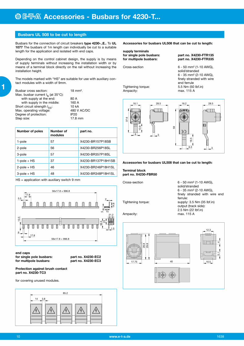
Busbars UL 508 to be cut to length
56x17.8 = 996.8
56x17.8 = 996.8
17.8
1.5
21.215
2
17.8
6
5.5
13.5
235
14.8
36.5
16.1 28.5 16.2 28.5
6 3
36.3
37.6
59
13.9
18.5
17.75 10.5
12.3
40
28.8
29.8
45.
1
14 3.8
85.2
Busbars for the connection of circuit breakers type 4230-..E.. To UL 1077 The busbars of 1m length can individually be cut to a suitable length for the application and isolated with end caps.
Depending on the control cabinet design, the supply is by means of supply terminals without increasing the installation width or by means of a terminal block directly on the rail without increasing the installation height.
The models marked with “HS” are suitable for use with auxiliary con-tact modules with a width of 9mm.
Busbar cross section: 18 mm².Max. busbar current Is (at 35°C): with supply at the end: 80 A with supply in the middle: 160 AShort circuit strength Icc: 10 kAMax. operating voltage: 480 V AC/DCDegree of protection: IP20Step size: 17.8 mm
Number of poles Number of modules
part no.
1-pole 57 X4230-BR157P18SB
2-pole 56 X4230-BR256P18SL
3-pole 57 X4230-BR357P18SL
1-pole + HS 37 X4230-BR137P18H1SB
2-pole + HS 46 X4230-BR246P18H1SL
3-pole + HS 48 X4230-BR348P18H1SL
Accessories for busbars UL508 that can be cut to length:
supply terminalsfor single pole busbars: part no. X4230-FTR135for multipole busbars: part no. X4230-FTR335
Cross-section 6 - 50 mm² (1-10 AWG), solid/stranded 6 - 35 mm² (2-10 AWG), finely stranded with wire
end ferruleTightening torque: 5.5 Nm (50 lbf.in) Ampacity: max. 115 A
Accessories for busbars UL508 that can be cut to length:
Terminal blockpart no. X4230-FBR50
Cross-section 6 - 50 mm² (1-10 AWG), solid/stranded 6 - 35 mm² (2-10 AWG), finely stranded with wire end
ferrule:Tightening torque: supply: 3.5 Nm (35 lbf.in) output (track side): 2.5 Nm (22 lbf.in)Ampacity: max. 115 A
end capsfor single pole busbars: part no. X4230-EC2for multipole busbars: part no. X4230-EC3
Protection against brush contactpart no. X4230-TC3
for covering unused modules.
HS = application with auxiliary switch 9 mm
www.e-t-a.de 11
Accessories - Busbars for 4230-T...
1638
1
Accessories - Busbars for 4230-T...
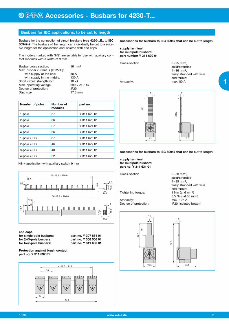
Busbars for IEC applications, to be cut to length
17.8
3.6 1.5
1
14.5
14.7
56x17.8 = 996.8
17.8
11.7
4.6
17,5
15.8
29.2
4
56x17.8 = 996.8
6
1332
2
17.7
49.5
6
11
16.5
32.5
15
2
27.1
52.5
13
84.2
17.8
4x17.8 = 71.2
Busbars for the connection of circuit breakers type 4230-..E.. to IEC 60947-2. The busbars of 1m length can individually be cut to a suita-ble length for the application and isolated with end caps. The models marked with "HS" are suitable for use with auxiliary con-tact modules with a width of 9 mm.
Busbar cross section: 16 mm²Max. busbar current Is (at 35°C): with supply at the end: 80 A with supply in the middle: 130 AShort circuit strength Icc: 10 kAMax. operating voltage: 690 V AC/DCDegree of protection: IP20Step size: 17.8 mm
Accessories for busbars to IEC 60947 that can be cut to length:
supply terminalfor multipole busbars:part number Y 311 630 01
Cross-section 6 – 25 mm², solid/stranded 4 – 16 mm², finely stranded with wire
end ferrule:Ampacity: max. 80 A
Accessories for busbars to IEC 60947 that can be cut to length:
supply terminalfor multipole busbars:part no. Y 311 631 01
Cross-section 6 – 50 mm², solid/stranded 4 – 35 mm², finely stranded with wire
end ferrule:Tightening torque: 1 Nm (at 6 mm²) 3.5 Nm (at 50 mm²)Ampacity: max. 125 ADegree of protection: IP20, isolated bottom
end capsfor single pole busbars: part no. Y 307 851 01for 2-/3-pole busbars part no. Y 308 506 01for four-pole busbars: part no. Y 311 633 01
Protection against brush contactpart no. Y 311 632 01
Number of poles Number of modules
part no.
1-pole 57 Y 311 622 01
2-pole 56 Y 311 623 01
3-pole 57 Y 311 624 01
4-pole 56 Y 311 625 01
1-pole + HS 37 Y 311 626 01
2-pole + HS 46 Y 311 627 01
3-pole + HS 48 Y 311 628 01
4-pole + HS 52 Y 311 629 01
HS = application with auxiliary switch 9 mm

www.e-t-a.de 12 1638
1