thermal management of batteries using a hybrid ... · thermal management of batteries using a...
TRANSCRIPT

Thermal Management of Batteries Using a HybridSupercapacitor Architecture
Donghwa Shin, Massimo Poncino, and Enrico MaciiDipartimento di Automatica e Informatica, Politecnico di Torino
C.so Duca degli Abruzzi 24, 10129 Torino (ITALY)donghwa.shin, massimo.poncino, [email protected]
Abstract—Thermal analysis and management of batteries havebeen an important research issue for battery-operated systemssuch as electric vehicles and mobile devices. Nowadays, batterypacks are designed considering heat dissipation, and externalcooling devices such as a cooling fan are also widely used toenforce the reliability and extend the lifetime of a battery. Thistype of approaches that target the enhancement of the coolingefficiency via the reduction of the thermal resistance cannotachieve an immediate temperature drop to avoid a thermalemergency situation. Approaches based on removing the heatfrom the heat sources via idle period insertion (similar to whatis done for silicon devices) would allow faster thermal response;however it is not obvious how to implement these schemes in thecontext of batteries.
In this paper, we propose the use of a simple parallel battery-supercapacitor hybrid architecture with a dual-mode dischargingstrategy that can provide immediate temperature management,in which the supercapacitor is used as an energy buffer duringthe idle periods of the battery. Simulation results shows that theproposed method can keep the battery temperature within thesafe range without external cooling devices while exploiting theadvantage of the battery-supercapacitor parallel connection.
I. INTRODUCTION
Batteries are the most important energy source for themodern off-the-grid electric or electronic systems and theiruse is continuosly increasing due to the need of energy storageelements required by new application domains such as renew-able energy systems and electric vehicles. The lifetime andthe efficiency of a battery is largely affected by its operatingtemperature; the state-of-health (SOH)1 of the battery exposedto high temperature is seriously degraded. As an example, itis reported that the SOH of battery in the electric vehicles ina desert is 12% less than the vehicles in temperate climateregions after 10 years [1]. The battery generally needs to becooled down during discharging period, and also, sometimes,to be heated for the discharging efficiency in a cold condition.
Moreover, batteries are exposed to danger of thermal run-away where themselves also generate the heat during discharg-ing process. Thermal runaway happens when an uncontrolledpositive feedback loop is formed between the heat generationand temperature, which is often leading to a destructive
This work was supported by a grant from the National Research Foun-dation of Korea (NRF) funded by the Korean Government (MEST) (No.2012R1A6A3A03038938).
978-3-9815370-2-4/DATE14/ c©2014 EDAA1A normalized effective capacity of the battery after multiple charge-
discharge cycles
result. Thermal runaway of lithium-ion batteries have beenreported in cellphones and laptop computers occasionally. Thebasic solution is to use less reactive electrode materials andnon-flammable electrolytes, but it is clear that the operatingcondition also should be maintained properly.
In general, we can have two categories of active thermalmanagement methods: thermal resistance2control and heat-source control [2]. The first category attempt at improving howthe heat is removed. For instance, modern microprocessors canbe cooled down by using a heat sink and forced-convectioncooling devices such as an electric fan or a coolant pump. Thefan or pump enhance the heat-transfer efficiency (i.e., reducethe thermal resistance) by increasing the amount of coolantfluid through the heat-exchange channel.
A problem with these approaches is that the cooling deviceused for the forced convection also consumes substantialamount of power; for instance, in the case of fans, their powerconsumption is proportional to the cubic of fluid velocity [3].Another critical limit of the thermal resistance control is thatit cannot respond to a sudden temperature drop to avoid athermal emergency unless it can suddenly change the thermalresistance in a thermal equilibrium. Heat source control meth-ods, conversely, act directly on the generation of heat ratherthan just removing it; this is typically done by inserting idleperiods during system operations. While this is quite standardfor digital components, it is apparently not obvious how itcould be implemented for energy storage devices.
As a matter of fact, batteries have no equivalent of thepower/performance states of digital devices; moreover supplyof energy cannot be simply suspended as done for computa-tion: when a battery is disconnected, the system will be shut-down. To avoid this, we need an energy buffer that powersthe system while idle periods are inserted into the batterydischarging profile. Such energy buffer could be a redundantbattery, but this is not a very practical solution in terms ofcost and form factor. Furthermore, the redundant battery willundergo the same thermal problem.
The ideal storage buffer should have the following charac-teristics: i) have large enough energy capacity to cover theidle period, ii) have much lower internal resistance than thebattery (less ohmic heat-generation, thus not subject to thermalproblems), and iii) allow high number of charge/discharge
2The reciprocal of thermal conductance.
cycles (higher than batteries) in order to make the frequentcharging-discharging operation possible.
The most suitable candidate for the energy buffer device sat-isfying that requirements is an electric double-layer capacitors,or simply supercapacitors, the supercapacitors have extremelylow internal resistance and virtually unlimited cycle numbercompared to the battery [4], and have been widely adoptedinto various hybrid energy storage systems. Even the simplesthybrid architecture - a parallel connection - have been reportedto have significant advantage in terms of cycle efficiency.
In this paper, we propose a smart way of using the superca-pacitor in the battery-supercapacitor parallel connection. Theproposed dual-mode battery-supercapacitor hybrid architectureenables immediate temperature control of the batteries whileexploiting the advantage of the parallel connection. We showthe feasibility of the proposed hybrid architecture and presenta control policy to properly configure what storage device isconnected to the load and when, depending on temperatureand the respective state of charge (SOC) of the storage deviceswith a realistic load condition on a electric vehicle.
II. RELATED WORK
Thermal analysis and management of batteries have beenan important research issue for electric vehicles. An effect oftemperature on SOH degradation in the electric vehicles wasanalyzed in [5]. A simulation model to evaluate the effectof thermal management on battery life was presented in [6].Battery pack designs was also investigated in terms of electro-chemistry and fluid dynamics in [7]. A pre-heating methodas well as a cooling method for the battery in cold climatewas introduced in [8]. The requirement for the battery coolingmethod considering a climate condition was presented in [1].
Supercapacitors are gaining more attention as an electricalenergy storage element in various applications thanks to itshigh cycle efficiency and long lifetime properties. Severalbattery-supercapacitor hybrid architectures for the hybrid en-ergy systems have been proposed in the literature. A bidirec-tional converter based approach was introduced for equippedwith electric vehicles regenerative braking [9]. An analysisof the hybrid system considering operating conditions andsupercapacitor configuration was performed in [10].
The most basic, yet effective, hybrid architecture is a su-percapacitor and a battery in parallel. It supports a higher rateof discharging power thanks to the high power density of thesupercapacitor, and thus, enhances the discharging efficiencyunder load fluctuations [11]: the supercapacitor behaves infact as a filter that relieves peak stresses on the battery. Thesupercapacitor also serves a thermal management function byreducing the current-induced heat generation at the internalresistance of the batteries, though this is just a side effect.To the best of our knowledge, there have been no attempt touse the hybrid architecture in terms of thermal managementso far. The supercapacitors have been only used to enhancethe power capacity and cycle efficiency as a power buffer ora load fluctuation filter.
III. BATTERY MODEL
A. Thermal model
Tbat
Pbat
Pb2a Ta
Rb2a
Cbat
(a) Thermal circuit model for unit cell
(b) Thermal RC network model for battery pack
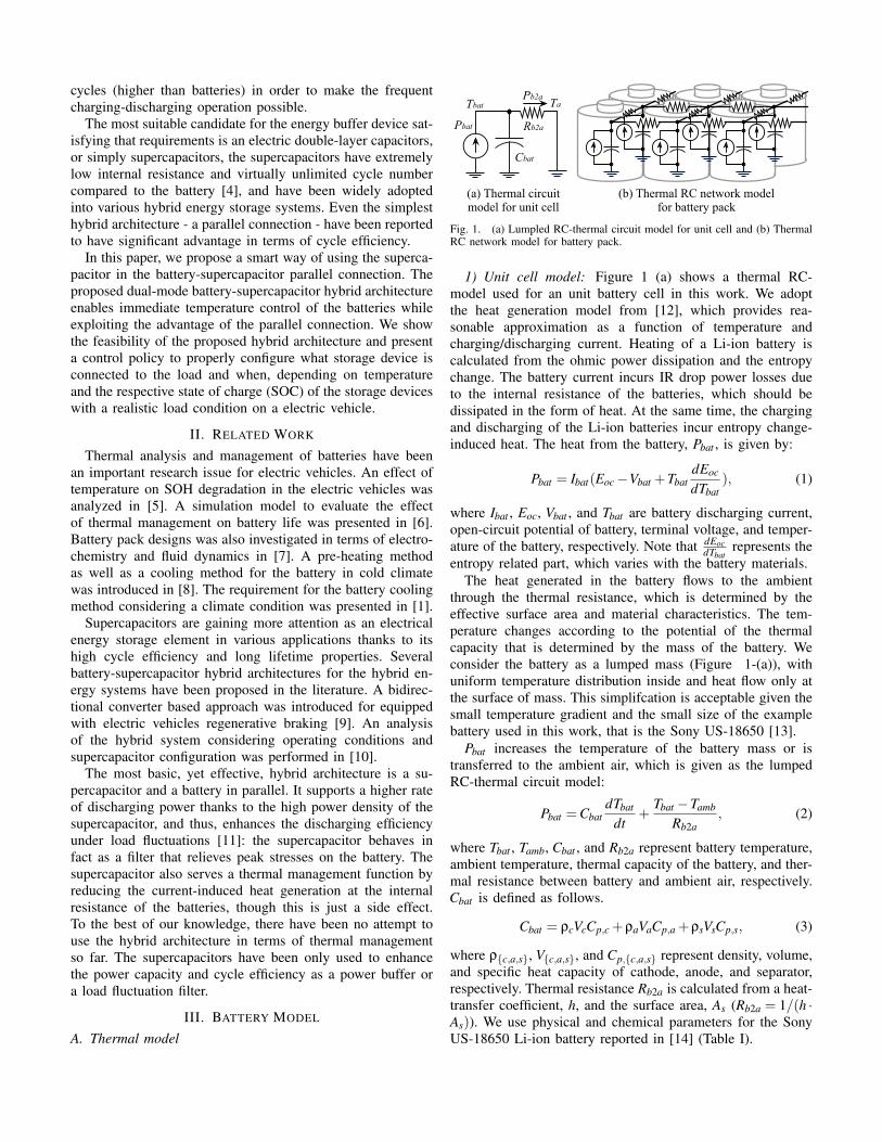
Fig. 1. (a) Lumpled RC-thermal circuit model for unit cell and (b) ThermalRC network model for battery pack.
1) Unit cell model: Figure 1 (a) shows a thermal RC-model used for an unit battery cell in this work. We adoptthe heat generation model from [12], which provides rea-sonable approximation as a function of temperature andcharging/discharging current. Heating of a Li-ion battery iscalculated from the ohmic power dissipation and the entropychange. The battery current incurs IR drop power losses dueto the internal resistance of the batteries, which should bedissipated in the form of heat. At the same time, the chargingand discharging of the Li-ion batteries incur entropy change-induced heat. The heat from the battery, Pbat , is given by:
Pbat = Ibat(Eoc−Vbat +TbatdEoc
dTbat), (1)
where Ibat , Eoc, Vbat , and Tbat are battery discharging current,open-circuit potential of battery, terminal voltage, and temper-ature of the battery, respectively. Note that dEoc
dTbatrepresents the
entropy related part, which varies with the battery materials.The heat generated in the battery flows to the ambient
through the thermal resistance, which is determined by theeffective surface area and material characteristics. The tem-perature changes according to the potential of the thermalcapacity that is determined by the mass of the battery. Weconsider the battery as a lumped mass (Figure 1-(a)), withuniform temperature distribution inside and heat flow only atthe surface of mass. This simplifcation is acceptable given thesmall temperature gradient and the small size of the examplebattery used in this work, that is the Sony US-18650 [13].
Pbat increases the temperature of the battery mass or istransferred to the ambient air, which is given as the lumpedRC-thermal circuit model:
Pbat =CbatdTbat
dt+
Tbat −Tamb
Rb2a, (2)
where Tbat , Tamb, Cbat , and Rb2a represent battery temperature,ambient temperature, thermal capacity of the battery, and ther-mal resistance between battery and ambient air, respectively.Cbat is defined as follows.
Cbat = ρcVcCp,c +ρaVaCp,a +ρsVsCp,s, (3)
where ρc,a,s, Vc,a,s, and Cp,c,a,s represent density, volume,and specific heat capacity of cathode, anode, and separator,respectively. Thermal resistance Rb2a is calculated from a heat-transfer coefficient, h, and the surface area, As (Rb2a = 1/(h ·As)). We use physical and chemical parameters for the SonyUS-18650 Li-ion battery reported in [14] (Table I).
Cb
Ibat
SOCZbat(SOC)
Vbat
EOC(SOC)
Ibat
(a) Li-ion battery equivalent cir-cuit model.
SOC (%)
ESRbat (Ω)0.22
0.18
0.14
0 100200 20 40 60 80 1000.12
0.14
0.16
0.18
0.2
0.22
Rbat (ohm)
SOC (%) 806040
(b) Equivalent ESR vs. SOC.
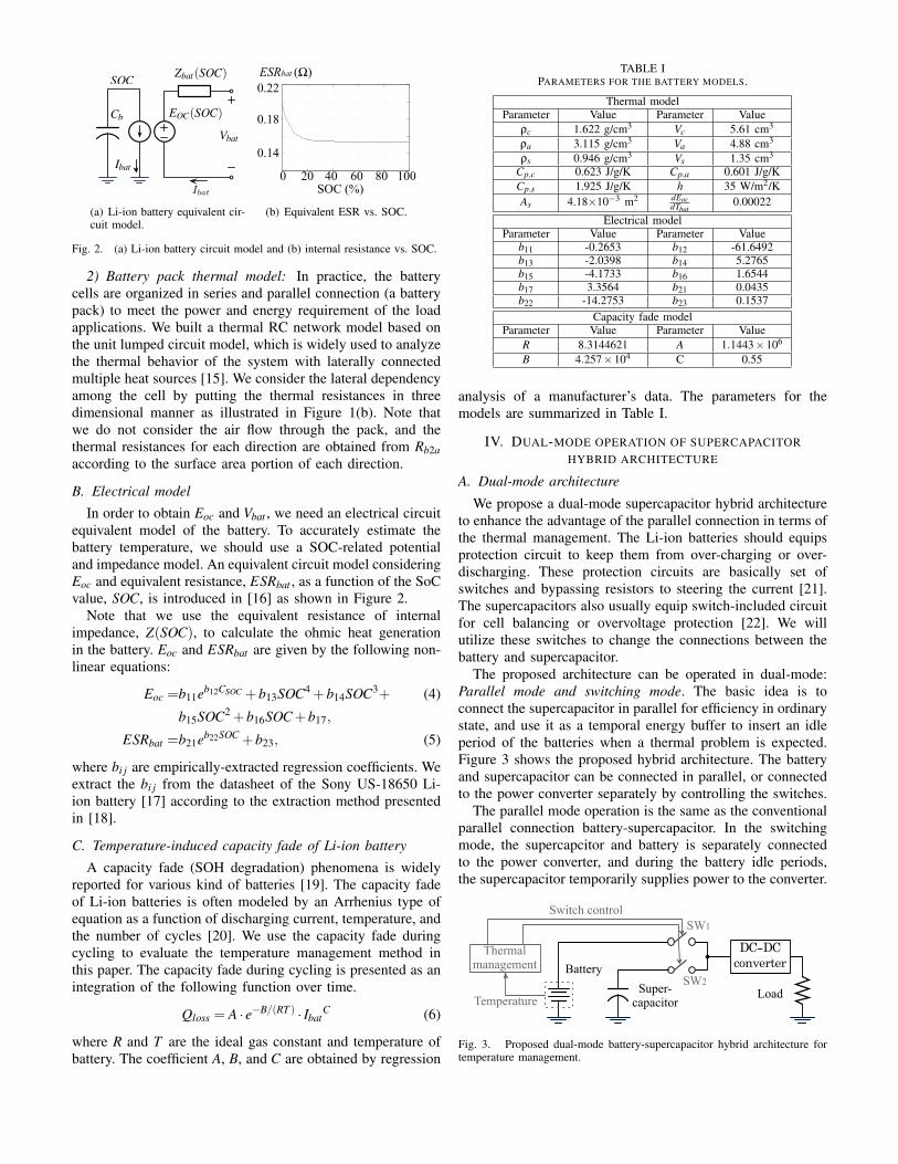
Fig. 2. (a) Li-ion battery circuit model and (b) internal resistance vs. SOC.
2) Battery pack thermal model: In practice, the batterycells are organized in series and parallel connection (a batterypack) to meet the power and energy requirement of the loadapplications. We built a thermal RC network model based onthe unit lumped circuit model, which is widely used to analyzethe thermal behavior of the system with laterally connectedmultiple heat sources [15]. We consider the lateral dependencyamong the cell by putting the thermal resistances in threedimensional manner as illustrated in Figure 1(b). Note thatwe do not consider the air flow through the pack, and thethermal resistances for each direction are obtained from Rb2aaccording to the surface area portion of each direction.
B. Electrical model
In order to obtain Eoc and Vbat , we need an electrical circuitequivalent model of the battery. To accurately estimate thebattery temperature, we should use a SOC-related potentialand impedance model. An equivalent circuit model consideringEoc and equivalent resistance, ESRbat , as a function of the SoCvalue, SOC, is introduced in [16] as shown in Figure 2.
Note that we use the equivalent resistance of internalimpedance, Z(SOC), to calculate the ohmic heat generationin the battery. Eoc and ESRbat are given by the following non-linear equations:
Eoc =b11eb12CSOC +b13SOC4 +b14SOC3+ (4)
b15SOC2 +b16SOC+b17,
ESRbat =b21eb22SOC +b23, (5)
where bi j are empirically-extracted regression coefficients. Weextract the bi j from the datasheet of the Sony US-18650 Li-ion battery [17] according to the extraction method presentedin [18].
C. Temperature-induced capacity fade of Li-ion battery
A capacity fade (SOH degradation) phenomena is widelyreported for various kind of batteries [19]. The capacity fadeof Li-ion batteries is often modeled by an Arrhenius type ofequation as a function of discharging current, temperature, andthe number of cycles [20]. We use the capacity fade duringcycling to evaluate the temperature management method inthis paper. The capacity fade during cycling is presented as anintegration of the following function over time.
Qloss = A · e−B/(RT ) · IbatC (6)
where R and T are the ideal gas constant and temperature ofbattery. The coefficient A, B, and C are obtained by regression
TABLE IPARAMETERS FOR THE BATTERY MODELS.
Thermal modelParameter Value Parameter Value
ρc 1.622 g/cm3 Vc 5.61 cm3
ρa 3.115 g/cm3 Va 4.88 cm3
ρs 0.946 g/cm3 Vs 1.35 cm3
Cp,c 0.623 J/g/K Cp,a 0.601 J/g/KCp,s 1.925 J/g/K h 35 W/m2/KAs 4.18×10⁻³ m2 dEoc
dTbat0.00022
Electrical modelParameter Value Parameter Value
b11 -0.2653 b12 -61.6492b13 -2.0398 b14 5.2765b15 -4.1733 b16 1.6544b17 3.3564 b21 0.0435b22 -14.2753 b23 0.1537
Capacity fade modelParameter Value Parameter Value
R 8.3144621 A 1.1443×10⁶
B 4.257×10⁴ C 0.55
analysis of a manufacturer’s data. The parameters for themodels are summarized in Table I.
IV. DUAL-MODE OPERATION OF SUPERCAPACITORHYBRID ARCHITECTURE
A. Dual-mode architecture
We propose a dual-mode supercapacitor hybrid architectureto enhance the advantage of the parallel connection in terms ofthe thermal management. The Li-ion batteries should equipsprotection circuit to keep them from over-charging or over-discharging. These protection circuits are basically set ofswitches and bypassing resistors to steering the current [21].The supercapacitors also usually equip switch-included circuitfor cell balancing or overvoltage protection [22]. We willutilize these switches to change the connections between thebattery and supercapacitor.
The proposed architecture can be operated in dual-mode:Parallel mode and switching mode. The basic idea is toconnect the supercapacitor in parallel for efficiency in ordinarystate, and use it as a temporal energy buffer to insert an idleperiod of the batteries when a thermal problem is expected.Figure 3 shows the proposed hybrid architecture. The batteryand supercapacitor can be connected in parallel, or connectedto the power converter separately by controlling the switches.
The parallel mode operation is the same as the conventionalparallel connection battery-supercapacitor. In the switchingmode, the supercapcitor and battery is separately connectedto the power converter, and during the battery idle periods,the supercapacitor temporarily supplies power to the converter.
Battery
LoadSuper-capacitor
Thermal management
Temperature
SW1
SW2
Switch control
Fig. 3. Proposed dual-mode battery-supercapacitor hybrid architecture fortemperature management.

!"
$
"Tbat#Tem
) VbatVsc
&Esc#Pload /fsw
%t# 1/fsw
(Ibat# Ibat, max
t# 1/fsw
"
*EscPload /fsw
'TbatTem
Fig. 4. Control policy of the proposed dual-mode hybrid architecture.
As a result, the battery is immediately cooled down withoutinternal heat generation. Note that the thermal contribution ofthe supercapacitors is ignored in the experiment where theinternal resistance of the supercapacitor is hundreds of timessmaller than that of batteries [23].
B. Control policyFigure 4 shows the state diagram of the controller that
regulates the transition between the modes. At first, the batteryand supercapacitor are connected in parallel and charged up tothe same voltage in the parallel mode. Note that the chargingprocess of the battery is a virtually completely controlledprocess compared to the discharging process. In this sense,we are focusing on the discharging process, and assume thatthe battery and supercapacitor are given in charged state to thesame voltage.
The specific operation modes are described as transitions inFigure 4 1© – 7©. The system normally operates in parallelmode (leftmost state in Fig. 4). The battery switch (SW1) andsupercapacitor switch (SW2) are connected. once Tbat becomesgreater or equal to the emergency temperature Tem, then thebattery is disconnected and the operating mode is changeto the switching mode ( 1©). SW1 is disconnected and SW2is connected during an idle period, which is derived frompre-determined power gate switching frequency, fsw. Afterthe thermal idle period, the battery is re-connected and thesupercapacitor is disconnected during the same period ( 2©).If Tbat is still higher than Tem and the supercapacitor energy(Esc) is enough for the required energy of next thermal idleperiod, then another idle period is inserted ( 3©). Otherwise,the controller goes to the fail state and the both of switchesare disconnected ( 7©).
If Tbat drops lower than Tem, then the battery and superca-pacitor are connected and the supercapacitor is re-charged toswitch back to parallel mode ( 4©). The battery current, Ibat ,is limited by switching of SW2 lower than the pre-determinedmaximum current Ibat,max ( 5©). The operating mode is changedagain to the parallel mode when the supercapacitor is chargedup to the same voltage of the battery ( 6©).
V. CASE STUDY: HYBRID SYSTEM DESIGN ANDOPTIMIZATION FOR ELECTRIC VEHICLES
A. Electric vehicle specification and driving profileWe perform the design space exploration of the proposed
architecture with a standard driving schedule of the vehicles:
0 56Cscap (F)0
Efficiency Tpeak ()
0.5 60
64
20000 40000 60000
1Battery cycle efficiency Max. Tpeak
0 1 2 3 4 5 6 7104
0
0.25
0.5
0.75
1
Capacitance (F)
Effic
ienc
y
0 1 2 3 4 5 6 7104
22.5
23
23.5
T bat (‘
c)
58
62Effiency
Knee point
Fig. 5. Estimated battery cycle efficiency and average temperature withdifferent sizes of supercapacitor in parallel for US06 driving profile.
EPA US06 test procedure [24]. The power profile of theelectric vehicles with the driving schedule is obtained froma vehicle simulator named ADVISOR, which provides wholevehicle-level simulation with the standard test driving sched-ules [25]. We use the default configuration of electric vehicle(ev_default_in) provided in ADVISOR.
The battery pack in the target vehicle has 12 V outputvoltage and 25 kW power capacity. We uses 60×20×3 batterypack with the Sony US-18650 battery as an unit battery tomeet the capacity and voltage. We consider the lateral thermaldependency among the cells in the battery pack with the modelpresented in Section III-A2. The temperature is calculated bythe SPICE simulation of RC-thermal circuit. Note that thetarget vehicle model does not provide regenerative braking.
B. Design space exploration of hybrid setup
1) Size of supercapacitor: The capacity of energy bufferis determined by the size of the supercapacitor and the inputrange of the power converter. We can utilize the energy inthe supercapapcitor as long as the terminal voltage of thesupercapacitor remains within the input range of the DC-DCconverter. It is generally expected that large supercapacitorboosts the power capacity of the hybrid system and reduces theload fluctuation more effectively. However, we cannot increasethe size of supercapacitor as we want where the volumetricenergy density and cost of supercapacitor limit the size ofsupercapacitor in the hybrid system. As a result, the energyportion of the supercapacitor in the battery-supercapacitor hy-brid system is typically just few percent of battery energy [26].
Figure 5 shows the estimation result of battery cycle ef-ficiency (charging-discharging) and peak temperature, Tpeak,with different size of supercapacitor (Cscap) in parallel. Tpeakis defined as the highest temperature among the cells in apack, which is used for the controller input. We use thetarget load profile and battery pack specification introducedin Section V-A for the evaluation. As Cscap increasing, therelative effect on temperature is decreasing. The cycle ef-ficiency keeps increasing at the same time, but there is aknee point in the efficiency curve. We will explore the hybridsetups that have capacitance value around the efficiency kneepoint (5000 F to 25000 F) in the experiment, which can beregarded as a reasonable range (0.4% to 2% of the batteryenergy). Note that we optimize the size of supercapacitor in theparallel connection in terms of efficiency, and then try to usethe supercapacitor for thermal management where a parallelconnection is widely adopted architecture. In this paper, we

Zbat(SOC)
R1
R2
C
Fig. 6. Battery internal impedance model.
focus on the advanced operating policy of existing parallelconnection architecture to utilized the supercapacitors for thethermal management.
2) Power source switching frequency: Concerning idle pe-riod insertion, we can leverage some results from the modeland literature.
Observation 1: The heat generation model presented in(1) is convex with respect to the current where the heat isproportional to the square of the current. In terms of the heatgeneration, we should prefer less fluctuated current profile.Therefore, it is better to use a higher switching frequency thatcan be filtered by impedance to reduce the fluctuation wherethe impedance of the battery acts like a low-pass filter.
Observation 2: The switching of the power gates incursextra power consumption being proportional to the switch-ing frequency, which is given by Psw = CgV 2
gs fsw/2 whereCg, VDD, and fsw represent effective gate capacitance, gatedriving voltage, and the switching frequency of the switch,respectively [4].
The observations 1 and 2 present a tradeoff between theohmic heat and switching power loss related to fsw. Weoptimize the switching frequency based on the analysis ofthe battery heat and switching power loss. We use a typicalmodel of the battery impedance, Zbat , as a set of RC elementsas shown in Fig. 6 [27]. It is reported that target batteryhas a value of 110 mΩ, 40 mΩ, and 4 F for R1, R2,and C on average during 1 C discharging, respectively. Theparameters of SiR422DP N-channel MOSFET switch are usedto calculated the switching power loss Psw [28]. We use 2Camplitude, 50% duty pulsed discharge as a pulsed load, andfrom 0.1 Hz to 100 Hz switching frequencies are applied.
The estimated power loss in the battery internal resistanceand switching power loss are presented in Figure 7. Asillustrated in Figure 7 (b), 8 Hz is the lowest frequency that hasno additional effect on Pbat (heat generated from the battery).The switching power loss with 8 Hz switching frequency isabout 0.26 µW, which is a negligible value compared to the
10ï1 100 101 1020.66
0.68
0.7
0.72
0.74
0.76
0.78
fSW (Hz)
P bat (W
)
10ï1 100 101 102ï4
ï3
ï2
ï1
0
fSW (Hz)
P bat (W
)
10ï1 100 101 1020
0.3
0.6
0.9
1.2
1.5
1.8
P SW (u
W)
10ï1 100 101 1020.66
0.68
0.7
0.72
0.74
0.76
0.78
fSW (Hz)
P bat (W
)
10ï1 100 101 102ï4
ï3
ï2
ï1
0
fSW (Hz)
P bat (W
)
10ï1 100 101 1020
0.3
0.6
0.9
1.2
1.5
1.8
P SW (u
W)
0
-2
-40.66 0
fsw (s)10-1
(a) Pbat and Psw with different switching frequency
(b) ∆Pbat/∆Psw with different switching frequency
Pbat (W) Psw (uW)
Pbat
Psw
0.70
0.74
0.78
0.6
1.2
1.8
100 101 102
fsw (s)10-1 100 101 102
-3
-1
× 106
∆Pba
t/∆Ps
w
8Hz
Fig. 7. (a) Pbat , Psw and (b) ∆Psw∆Psw
with difference switching frequency.
TABLE IIDISCHARGING TIME OF THE PARALLEL CONNECTION AND THE
DUAL-MODE OPERATION WITH DIFFERENT TemAND Cscap .
Tem Simulation Cscap (F)(°C) results 5000 10000 15000 20000 25000
64t parldchg (s) 2702 2725 2982 2982 2983
tdualdchg (s) 2702 2725 2982 2982 2983
Extension (%) - - - - -
62t parldchg (s) 2702 2725 2732 2735 2739
tdualdchg (s) 2702 2725 2982 2982 2983
Extension (%) - - 9.1 9.0 8.9
60t parldchg (s) 2131 2134 2201 2724 2726
tdualdchg (s) 2136 2735 2982 2982 2983
Extension (%) 0.2 28.2 35.5 9.5 9.4
58t parldchg (s) 2120 2123 2125 2126 2132
tdualdchg (s) 2125 2705 2784 2982 2983
Extension (%) 0.2 27.4 31.0 40.3 39.9
56t parldchg (s) 1534 1584 1617 2103 2120
tdualdchg (s) 1607 2124 2722 2983 2983
Extension (%) 4.4 34.1 68.4 41.8 40.7
total amount of battery power (≈ 4.2V×1.6A = 6.4W). Weuse 8 Hz as fsw in the experiment based on this result. Notethat the IR loss in the switches is relatively huge compared tothe swatching loss, but it is the same as the loss due to theprotection circuits. We do not consider IR loss as overheadwhere it is not newly introduced by the proposed method.
C. Experimental resultTable II summarizes the discharging time of the parallel con-
nection (t parldchg) and dual-mode operation (tdual
dchg) with differentTem and Cscap. We use 5000 F to 25000 F of supercapacitorand 8 Hz fsw according to Section V-B. It shows stepwiseaspect due to the periodic characteristics of the load profile.In general, the larger Cscap extends the longer discharging timeeven with the lower Tem. With high enough Tem (64°C), theparallel connection shows the same performance with the dual-mode operation. However, the proposed dual-mode operationsignificantly extends the discharging time for lower Tem (up to68.4% with 56 °C as Tem).
Fig. 8 shows the temperature and current profile of theconventional parallel connection and proposed dual-mode op-eration when Tem is with 56 °Cand Cscap is 20000 F. T parl
peakand T dual
peak represent the highest temperature in the battery packwith the parallel connection and dual-mode operation. tdual
dchg is41.8% longer than t parl
dchg, where T parlpeak meets Tem at 2103 s, and
T dualpeak meets Tem at 2983 s, respectively. Before 2103 s, both
of profiles are the same.T parl
peak presented in Fig. 8 1© shows what will happen whenwe discharge the battery in the parallel connection after thethermal emergency. T parl
peak keeps rising up to 62.9 °C whileT dual
peak is maintained under 56 °C (Fig. 8 2©) by the idle periodsinserted in Fig. 8 3©. If we continue to discharge the batteryin the parallel connection, it results in extra capacity fadecompared to the dual-mode even for the same dischargingtime. The estimated capacity fade of the dual-mode operationis 14.88% less than that of the parallel connection by (6).Table III shows the estimated capacity fade reduction when

60
30
40
50
0 500 1000 1500 2000 2500 300020
30
40
50
60
Time (s)
T peak
(C)
0 500 1000 1500 2000 2500 30000
2
4
6
Time (s)
I bat (A
)
0 500 1000 1500 2000 2500 30000
2
4
6
Time (s)
I bat (A
)
0 500 1000 1500 2000 2500 300020
30
40
50
60
Time (s)
T peak
(C)
0 500 1000 1500 2000 2500 30000
2
4
6
Time (s)
I bat (A
)
0 500 1000 1500 2000 2500 30000
2
4
6
Time (s)
I bat (A
)
0 500 1000 1500 2000 2500 300020
30
40
50
60
Time (s)
T peak
(C)
0 500 1000 1500 2000 2500 30000
2
4
6
Time (s)
I bat (A
)
0 500 1000 1500 2000 2500 30000
2
4
6
Time (s)
I bat (A
)Ib
at (A
)
2
64
2
64
Ibat
(A)
Tem
pera
ture
()
20
0
0
Tem (56 )
= 2983 stdualdchg
= 2103 s tparldchg
T dualpeakMax. = 56
= 62.9 Max. T parl
peak
①
②
③ Idle periods
Time (s)1000 20000
T dualpeak
T parlpeak
500 1500 2500
Fig. 8. Current and temperature profile of the battery pack with US06 drivingschedule thermal idle period-inserted battery-supercapacitor hybrid.
we discharge the parallel connection and dual-mode for thesame time (tdual
dchg) in Table II. The maximum difference of T parlpeak
and T dualpeak is up to 6.9°C, and the proposed method reduces
the capacity fade up 14.88% by maintaining the temperatureunder Tem.
VI. CONCLUSION
In terms of the efficiency and reliability, the battery-supercapacitor hybrid system has significant advantages. Thesupercapacitors have been used as a power buffer or a loadfluctuation filter for the efficiency so far. On the other hand,we can also use the supercapacitors in the hybrid systems as anenergy buffer to insert the thermal idle periods. In this paper,we propose a dual-mode hybrid architecture for the batteryand supercapacitor, which can make immediate temperature
TABLE IIIPEAK TEMPERATURE OF THE PARALLEL CONNECTION AND THEDUAL-MODE OPERATION WITH THE SAME DISCHARGING TIME.
Tem Simulation Cscap (F)(°C) results 5000 10000 15000 20000 25000
64T parl
peak (°C) 61.6 61.5 63.5 62.9 62.5T dual
peak (°C) 61.6 61.5 63.5 62.9 62.5Qloss reduction (%) - - - - -
62T parl
peak (°C) 61.6 61.4 63.5 62.9 62.5T dual
peak (°C) 61.6 61.4 62.0 62.0 62.0Qloss reduction (%) - - 2.15 1.4 0.74
60T parl
peak (°C) 60.9 61.4 63.5 62.9 62.5T dual
peak (°C) 60.0 60.0 60.0 60.0 60.0Qloss reduction (%) 1.24 2.44 5.53 4.28 3.64
58T parl
peak (°C) 59.2 61.0 63.2 62.9 62.5T dual
peak (°C) 58.0 58.0 58.0 58.0 58.0Qloss reduction (%) 1.50 6.81 9.21 9.65 8.55
56T parl
peak (°C) 56.6 58.4 60.5 62.9 62.5T dual
peak (°C) 56.0 56.0 56.0 56.0 56.0Qloss reduction (%) 1.53 4.45 11.31 14.88 13.75
change of the battery while exploiting the advantage of theconventional battery-supercapacitor parallel connection.
We propose a control policy for the proposed dual-modehybrid architecture based on the practical observations. Wedesign the system with the realistic operating condition of theelectric vehicles and present the feasibility of the proposedmethod. The experimental result shows that the proposed dual-mode hybrid architecture is able to maintain the temperature ofthe battery within a pre-determined safe range with the benefitof discharging time extension or capacity fade reduction.
REFERENCES
[1] U.S. Department of Energy, “Automotive li-ion battery cooling require-ments,” 2012. http://www.eere.energy.gov.
[2] D. Brooks and et al., “Dynamic thermal management for high-performance microprocessors,” in HPCA, 2001.
[3] D. Shin and et al., “Energy-optimal dynamic thermal management:Computation and cooling power co-optimization,” IEEE TII, 2010.
[4] D. Shin and et al., “Constant-current regulator-based battery-supercapacitor hybrid architecture for high-rate pulsed load applica-tions,” Journal of Power Sources, 2012.
[5] A. Millner, “Modeling lithium ion battery degradation in electric vehi-cles,” in CITRES, 2010.
[6] T. Yuksel and et al., “Evaluation of the effects of thermal managementon battery life in plug-in hybrid electric vehicles,” in Battery Congress,2012.
[7] M. Zolot and et al., “Thermal evaluation of toyota prius battery pack,”in Future Car Congress, 2002.
[8] A. Pesaran and et al., “Cooling and preheating of batteries in hybridelectric vehicles,” in AJTEC, 2003.
[9] S. Pay and et al., “Effectiveness of battery-supercapacitor combinationin electric vehicles,” in IEEE Bologna Power Tech Conference, 2003.
[10] G. Sikha and B. N. Popov, “Performance optimization of a battery-capacitor hybrid system,” Journal of Power Sources, 2004.
[11] C. E. Holland and et al., “Experimental characterization of hybrid powersystems under pulse current loads,” Journal of Power Sources, 2002.
[12] S. Chen and et al., “Thermal analysis of lithium-ion batteries,” Journalof Power Sources, 2005.
[13] T. D. Hatchard and et al., “Thermal model of cylindrical and prismaticlithium-ion cells,” Journal of The Electrochemical Society, 2001.
[14] H. Maleki and et al., “Thermal properties of lithiumion battery andcomponents,” Journal of The Electrochemical Society, 1999.
[15] R. P. Stout, “General thermal transient rc networks,” 2006. ONSemiconductor.
[16] D. Shin and et al., “Online estimation of the remaining energy capacityin mobile systems considering system-wide power consumption andbattery characteristics,” in ASP-DAC, 2013.
[17] Sony Corporation, “Lithium Ion Rechargeable Batteries Technical Hand-book.”
[18] M. Petricca and et al., “An automated framework for generating variable-accuracy battery models from datasheet information,” in ISLPED, 2013.
[19] Q. Xie and et al., “State of health aware charge management in hybridelectrical energy storage systems,” in DATE, 2012.
[20] T. Yuksel and et al., “Evaluation of the effects of thermal management onbattery life in plug-in hybrid electric vehicles,” in Society of AutomotiveEngineers World Congress, 2012.
[21] Texas Instrument, “LM3641 Lithium-Ion Battery Pack Protection Cir-cuit,” 2011.
[22] Maxwell technologies, “Datasheet: Ultracapacitor cell integration kit.”[23] Maxwell technologies, “Datasheet: Bc series ultracapacitors.”[24] U.S. Environmental Protection Agency, “Emission Standards Reference
Guide: EPA US06 or Supplemental Federal Test Procedure (SFTP).”http://www.epa.gov/.
[25] K. W. Matthew and et al., “Advisor 2.0: A second-generation advancedvehicle simulator for systems analysis,” in NAEVI, 1999.
[26] R. Sadoun and et al., “Sizing of hybrid supply (battery-supercapacitor)for electric vehicle taking into account the weight of the additional buck-boost chopper,” in REVET, 2012.
[27] L. Gao and et al., “Dynamic Lithium-ion battery model for systemsimulation,” IEEE TCPT, 2002.
[28] Vishay Siliconix, “SiR422DP N-Channel 40-V (D-S) MOSFET,” 2009.