thermal process technology - · pdf file made in germany furnaces and heat treatment plants...
TRANSCRIPT

www.nabertherm.com
MadeinGermany
Furnaces and Heat Treatment Plants for Processes under Protective or Reactive Gases or Vacuum
Retort FurnacesContinuous and Wire Annealing FurnacesTube FurnacesSalt-Bath FurnacesNitriding and Caburizing FurnacesFurnaces for Additive ManufacturingHardening Systems, Quenching BathsProtective Gas Boxes
Thermal Process Technology
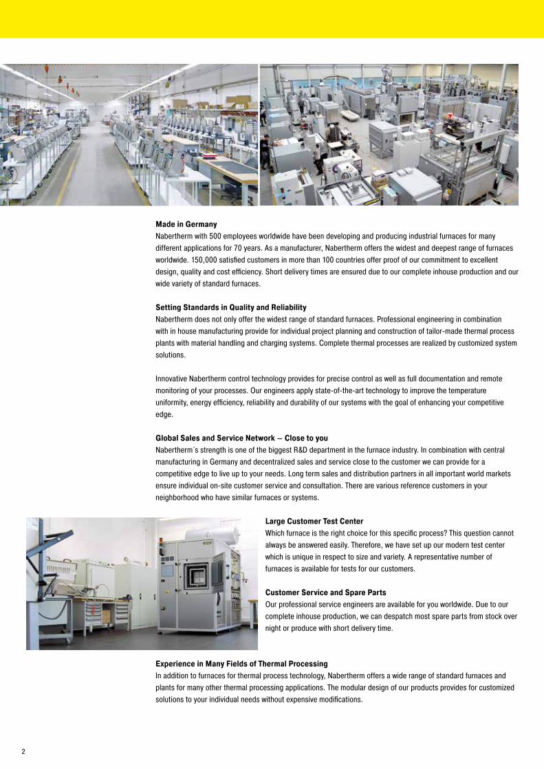
Made in GermanyNabertherm with 500 employees worldwide have been developing and producing industrial furnaces for many different applications for 70 years. As a manufacturer, Nabertherm offers the widest and deepest range of furnaces worldwide. 150,000 satisfied customers in more than 100 countries offer proof of our commitment to excellent design, quality and cost efficiency. Short delivery times are ensured due to our complete inhouse production and our wide variety of standard furnaces.
Setting Standards in Quality and ReliabilityNabertherm does not only offer the widest range of standard furnaces. Professional engineering in combination with in house manufacturing provide for individual project planning and construction of tailor-made thermal process plants with material handling and charging systems. Complete thermal processes are realized by customized system solutions.
Innovative Nabertherm control technology provides for precise control as well as full documentation and remote monitoring of your processes. Our engineers apply state-of-the-art technology to improve the temperature uniformity, energy efficiency, reliability and durability of our systems with the goal of enhancing your competitive edge.
Global Sales and Service Network – Close to youNabertherm´s strength is one of the biggest R&D department in the furnace industry. In combination with central manufacturing in Germany and decentralized sales and service close to the customer we can provide for a competitive edge to live up to your needs. Long term sales and distribution partners in all important world markets ensure individual on-site customer service and consultation. There are various reference customers in your neighborhood who have similar furnaces or systems.
Large Customer Test CenterWhich furnace is the right choice for this specific process? This question cannot always be answered easily. Therefore, we have set up our modern test center which is unique in respect to size and variety. A representative number of furnaces is available for tests for our customers.
Customer Service and Spare PartsOur professional service engineers are available for you worldwide. Due to our complete inhouse production, we can despatch most spare parts from stock over night or produce with short delivery time.
Experience in Many Fields of Thermal ProcessingIn addition to furnaces for thermal process technology, Nabertherm offers a wide range of standard furnaces and plants for many other thermal processing applications. The modular design of our products provides for customized solutions to your individual needs without expensive modifications.
2

Table of Contents
Page
Furnaces and Accessories for Heat Treatment of Metals ...................................................................... 4
Which Furnace for Which Process? ....................................................................................................... 6
Hardening, Carburizing, Nitriding, Brazing, MIM .................................................................................10
Additive Manufacturing, 3D-Printing ...................................................................................................12
Hot-Wall Retort Furnaces up to 1100 °C ...............................................................................................16
Cold-Wall Retort Furnaces up to 3000 °C............................................................................................ 26
Retort Furnace Cooling Systems ........................................................................................................ 33
Tube Furnaces for Processes under Flammable or Non-Flammable Protective or
Reaction Gases or under Vacuum .................................................................................................... 34
Wire and Strand Annealing Furnaces .................................................................................................. 36
Continuous Plants for Protective or Reaction Gas Atmospheres ..........................................................37
Salt-Bath Furnaces for Heat Treatment of Steel or Light Metals ......................................................... 38
Martempering Furnaces using Neutral Salts ........................................................................................41
Chamber Furnaces for Annealing and Hardening ................................................................................ 43
Annealing and Protective Gas Boxes, Additional Equipment for Models N 7/H - N 641/13 ............................ 44
Stainless Steel Heat Treating Foil to avoid Surface Reactions ............................................................ 50
Annealing and Heat Treating Foils ...................................................................................................... 50
Accessory Equipment for Processing Bags, Envelopes and Foils ....................................................... 50
Annealing Envelopes ...........................................................................................................................51
Annealing Bags ...................................................................................................................................51
Carburizing Granulate ........................................................................................................................ 52
Nitriding Powder and Activator ........................................................................................................... 52
Chamber Furnaces with Brick Insulation or Fiber Insulation ............................................................... 54
Protective Gas Boxes, Additional Equipment for Models LH 15/.. - LH 216/.. ............................................. 56
Chamber Furnaces with Drawer Bottom or as a Bogie ........................................................................ 58
Protective Gas Boxes and Hoods for Chamber Furnaces NW 150 - NW 1000 ............................................. 59
Forced Convection Chamber Furnaces < 675 Liters ............................................................................ 60
Protective Gas Boxes, Additional Equipment for Models NA 30/45 - N 500/85HA ...................................... 62
Sealed Forced Convection Chamber Furnaces NA-I and NA-SI ........................................................... 65
Forced Convection Pit-Type Furnaces ................................................................................................ 66
Protective Gas Boxes, Additional Equipment for Models SAL 30/45 - SAL 250/85 ..................................... 67
Temperature Measurement in Gas Supply Systems ............................................................................ 69
TUS Measuring Frame for Protective Gas Box ..................................................................................... 69
Tool Shop Hardening Systems ............................................................................................................ 70
Protective Gas Hardening System SHS 41 .......................................................................................... 73
Gas Supply Systems ............................................................................................................................74
Vacuum Pump ..................................................................................................................................... 75
Protection Clothing ............................................................................................................................ 76
Draw Hook, Binding Wire, Hardening Tongs ........................................................................................ 77
Cooling Platforms ............................................................................................................................... 78
Charging Devices with and without Cooling Fan for Models
N 31/H - N 641/13, N 30/45 HA - N 500/85 HA, LH (LF) 15/.. - LH (LF) 216/.. ................................... 78
Quenching and Cleaning Baths ........................................................................................................... 80
Hardening Oil, Quench Water Additive, Detergent, Insulating Materials ............................................. 82
Tailor-Made Furnace Plants ................................................................................................................ 83
Temperature Uniformity and System Accuracy .................................................................................... 84
AMS 2750 E, NADCAP, CQI-9 ............................................................................................................. 85
Process Control and Documentation .................................................................................................. 88
3
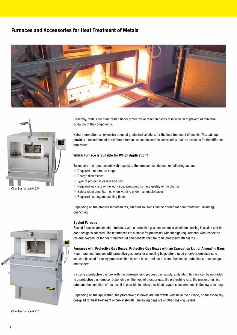
Chamber furnace N 7/H
Chamber furnace N 41/H
Generally, metals are heat treated under protective or reaction gases or in vacuum to prevent or minimize oxidation of the components.
Nabertherm offers an extensive range of graduated solutions for the heat treatment of metals. This catalog provides a description of the different furnace concepts and the accessories that are available for the different processes.
Which Furnace is Suitable for Which Application?
Essentially, the requirements with respect to the furnace type depend on following factors: � Required temperature range � Charge dimensions � Type of protective or reaction gas � Required leak rate of the work space/required surface quality of the charge � Safety requirements, i. e. when working under flammable gases � Required heating and cooling times
Depending on the process requirements, adapted solutions can be offered for heat treatment, including quenching.
Sealed FurnaceSealed furnaces are standard furnaces with a protective gas connection in which the housing is sealed and the door design is adapted. These furnaces are suitable for processes without high requirements with respect to residual oxygen, or for heat treatment of components that are to be processed afterwards.
Furnaces with Protective Gas Boxes, Protective Gas Boxes with an Evacuation Lid, or Annealing BagsHeat treatment furnaces with protective gas boxes or annealing bags offer a good price/performance ratio and can be used for many processes that have to be carried out in a non-flammable protective or reaction gas atmosphere.
By using a protective gas box with the corresponding process gas supply, a standard furnace can be upgraded to a protective gas furnace. Depending on the type of process gas, the preflushing rate, the process flushing rate, and the condition of the box, it is possible to achieve residual oxygen concentrations in the low ppm range.
Depending on the application, the protective gas boxes are removable, remain in the furnace, or are especially designed for heat treatment of bulk materials. Annealing bags are another gassing variant.
Furnaces and Accessories for Heat Treatment of Metals
4
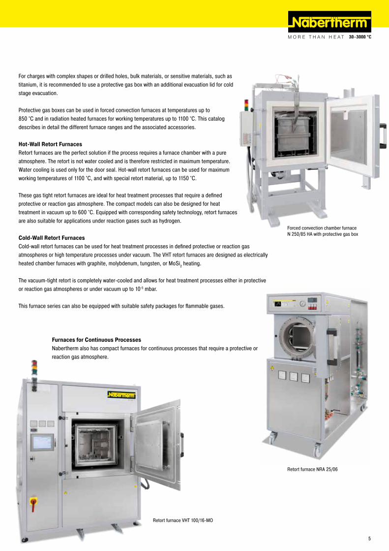
Retort furnace NRA 25/06
For charges with complex shapes or drilled holes, bulk materials, or sensitive materials, such as titanium, it is recommended to use a protective gas box with an additional evacuation lid for cold stage evacuation.
Protective gas boxes can be used in forced convection furnaces at temperatures up to 850 °C and in radiation heated furnaces for working temperatures up to 1100 °C. This catalog describes in detail the different furnace ranges and the associated accessories.
Hot-Wall Retort FurnacesRetort furnaces are the perfect solution if the process requires a furnace chamber with a pure atmosphere. The retort is not water cooled and is therefore restricted in maximum temperature. Water cooling is used only for the door seal. Hot-wall retort furnaces can be used for maximum working temperatures of 1100 °C, and with special retort material, up to 1150 °C.
These gas tight retort furnaces are ideal for heat treatment processes that require a defined protective or reaction gas atmosphere. The compact models can also be designed for heat treatment in vacuum up to 600 °C. Equipped with corresponding safety technology, retort furnaces are also suitable for applications under reaction gases such as hydrogen.
Cold-Wall Retort FurnacesCold-wall retort furnaces can be used for heat treatment processes in defined protective or reaction gas atmospheres or high temperature processes under vacuum. The VHT retort furnaces are designed as electrically heated chamber furnaces with graphite, molybdenum, tungsten, or MoSi2 heating.
The vacuum-tight retort is completely water-cooled and allows for heat treatment processes either in protective or reaction gas atmospheres or under vacuum up to 10-5 mbar.
This furnace series can also be equipped with suitable safety packages for flammable gases.
Forced convection chamber furnace N 250/85 HA with protective gas box
Retort furnace VHT 100/16-MO
Furnaces for Continuous ProcessesNabertherm also has compact furnaces for continuous processes that require a protective or reaction gas atmosphere.
5
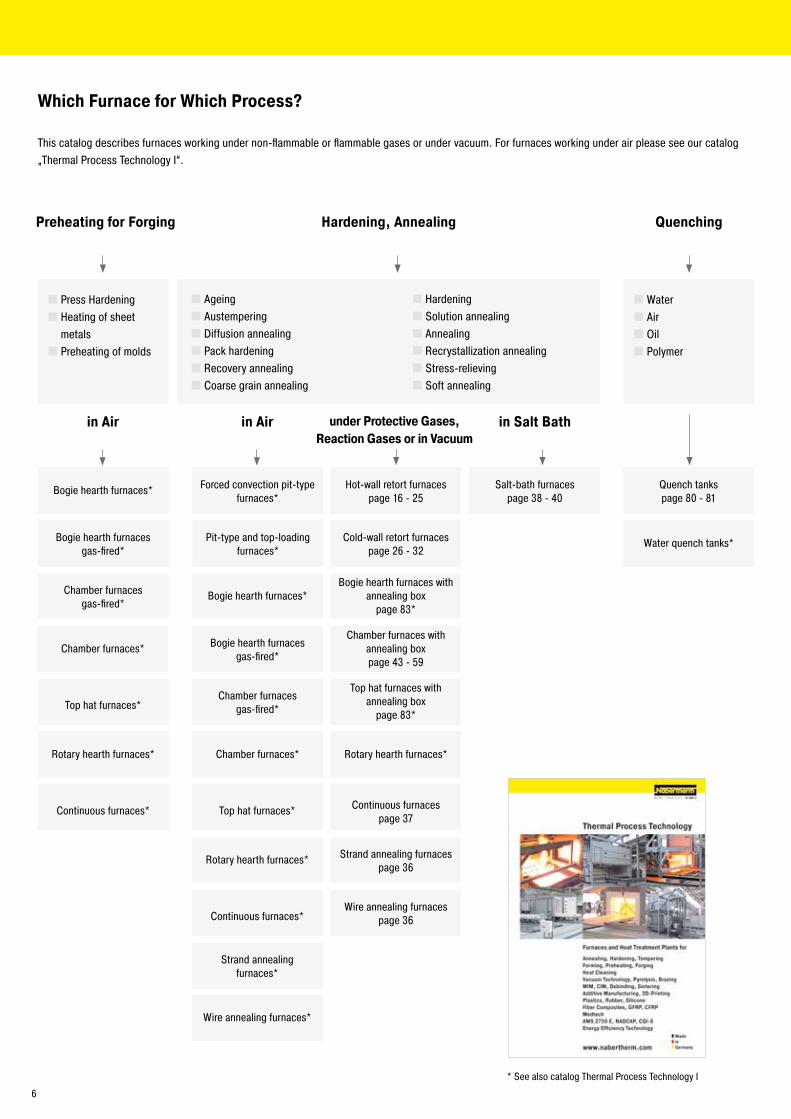
Which Furnace for Which Process?
Hardening, Annealing
in Air
Continuous furnaces*
Rotary hearth furnaces*
Top hat furnaces*
Chamber furnaces*
Chamber furnaces gas-fired*
Bogie hearth furnaces gas-fired*
Bogie hearth furnaces*
Forced convection pit-type furnaces*
Pit-type and top-loading furnaces*
Chamber furnaces gas-fired*
Continuous furnaces*
Rotary hearth furnaces*
Top hat furnaces*
Chamber furnaces*
Bogie hearth furnacesgas-fired*
Bogie hearth furnaces*
Preheating for Forging
� Press Hardening � Heating of sheet metals � Preheating of molds
� Ageing � Austempering � Diffusion annealing � Pack hardening � Recovery annealing � Coarse grain annealing
� Hardening � Solution annealing � Annealing � Recrystallization annealing � Stress-relieving � Soft annealing
in Salt Bathunder Protective Gases, Reaction Gases or in Vacuum
Rotary hearth furnaces*
Top hat furnaces with annealing box
page 83*
Chamber furnaces with annealing boxpage 43 - 59
Bogie hearth furnaces with annealing box
page 83*
Cold-wall retort furnacespage 26 - 32
Hot-wall retort furnacespage 16 - 25
Salt-bath furnacespage 38 - 40
Wire annealing furnaces*
Strand annealing furnaces*
Quenching
Water quench tanks*
Quench tankspage 80 - 81
�Water � Air � Oil � Polymer
in Air
Wire annealing furnacespage 36
Strand annealing furnacespage 36
Continuous furnacespage 37
* See also catalog Thermal Process Technology I
This catalog describes furnaces working under non-flammable or flammable gases or under vacuum. For furnaces working under air please see our catalog „Thermal Process Technology I“.
6
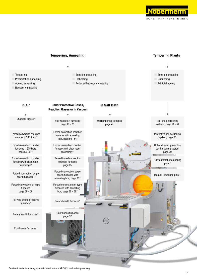
Tempering, Annealing
� Tempering � Precipitation annealing � Ageing annealing � Recovery annealing
in Air
� Solution annealing � Preheating � Reduced hydrogen annealing
Pit-type and top-loading furnaces*
Forced convection bogie hearth furnaces*
Forced convection chamber furnaces with clean room
technology*
Forced convection chamber furnaces < 675 liters
page 60 - 61*
Forced convection chamber furnaces > 560 liters*
Chamber dryers*
Continuous furnaces*
Rotary hearth furnaces*
Forced convection pit-type furnaces
page 66 - 68
Continuous furnacespage 37
Rotary hearth furnaces*
Forced convection pit-type furnaces with annealing
box, page 66 - 68*
Forced convection bogie hearth furnaces with
annealing box, page 83*
Forced convection chamber furnaces with clean room
technology*
Forced convection chamber furnaces with annealing
box, page 60 - 64
Hot-wall retort furnacespage 16 - 25
Martempering furnacespage 41
Tempering Plants
� Solution annealing � Quenching � Artificial ageing
Manual tempering plant*
Fully automatic tempering plant*
in Salt Bathunder Protective Gases, Reaction Gases or in Vacuum
Semi-automatic tempering plant with retort furnace NR 50/11 and water quenching
Sealed forced convection chamber furnaces
page 65
Hot-wall retort protective gas hardening system
page 20
Protective gas hardening system, page 73
Tool shop hardening systems, page 70 - 72
7

Brazing/Soldering
� Soft soldering � Brazing � High-temperature brazing
under Protective Gases
� Dip brazing of steel � Dip brazing of aluminum
in Vacuumin Salt Bath
Chamber furnaces with annealing box,page 43 - 59
Forced convection chamber furnaces with annealing
box, page 60 - 64
Cold-wall retort furnacespage 26 - 32
Hot-wall retort furnacespage 16 - 25
Salt-bath furnacespage 38 - 40
Curing, Tempering, Drying
� Composites � Molds � Adhesive � Plastics � Lacquers � PTFE
Ovens*
Forced convection chamber furnaces
page 60 - 61*
Chamber dryers*
Cold-wall retort furnacespage 26 - 32
Hot-wall retort furnacespage 16 - 25
� Silicone � Surface Drying � Preheating � Vulcanizing � Conditioning
Solvent Based Water Based
Which Furnace for Which Process?
Chamber dryers*
Forced convection chamber furnaces NA .. LS*
page 60 - 61
Hot-wall retort furnacespage 16 - 25
Rotary hearth furnaces*
Forced convection pit-type furnaces
page 60 - 68*
Forced convection bogie hearth furnaces*
Continuous furnaces*
Tube furnacespage 34 - 35**
Forced convection pit-type furnaces with annealing
box, page 66 - 68
Tube furnacespage 34 - 35**
*** See also catalog Advanced Materials* See also catalog Thermal Process Technology ** See also catalog Laboratory
8
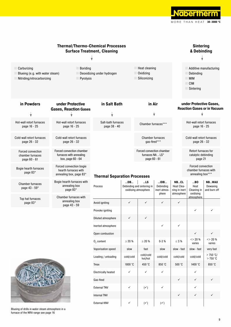
Blueing of drills in water steam atmosphere in a furnace of the NRA range see page 16
Thermal/Thermo-Chemical ProcessesSurface Treatment, Cleaning
� Carburizing � Blueing (e.g. with water steam) � Nitriding/nitrocarborizing
in Salt Bath
� Boriding � Deoxidizing under hydrogen � Pyrolysis
in Powders under Protective Gases, Reaction Gases
Salt-bath furnacespage 38 - 40
Chamber furnaces with annealing boxpage 43 - 59
Bogie hearth furnaces with annealing box
page 83*
Forced convection bogie hearth furnaces with
annealing box, page 83*
Forced convection chamber furnaces with annealing
box, page 60 - 64
Hot-wall retort furnacespage 16 - 25
Sintering & Debinding
� Additive manufacturing � Debinding � MIM � CIM � Sintering
Cold-wall retort furnacespage 26 - 32
Hot-wall retort furnacespage 16 - 25
under Protective Gases, Reaction Gases or in Vacuum
Chamber furnacespage 43 - 59*
Chamber furnaces gas-fired***
Bogie hearth furnacespage 83*
Forced convection chamber furnaces
page 60 - 61
Cold-wall retort furnacespage 26 - 32
Top hat furnacespage 83*
Cold-wall retort furnacespage 26 - 32
Hot-wall retort furnacespage 16 - 25
Retort furnaces for catalytic debinding
page 21
Forced convection chamber furnaces NA .. LS*
page 60 - 61
in Air
..DB.. ..LS ..IDB.. NB..CL ..BO NB..WAXProcess Debinding and sintering in
oxidising atmosphereDebinding
inert atmos-phere
Heat Clea-ning in inert atmosphere
Heat Cleaning in oxidising
atmosphere
Dewaxing and burn off
Avoid igniting
Provoke igniting
Diluted atmosphere
Inerted atmosphere
Open combustion
O2 content ≥ 20 % ≥ 20 % 0-3 % ≤ 3 % <> 20 % varies
<> 20 % varies
Vaporisation speed slow fast slow slow - fast slow - fast very fast
Loading / unloading cold/cold cold/coldhot/hot cold/cold cold/cold cold/cold > 750 °C/
> 750 °C
Tmax 1800 °C 450 °C 850 °C 500 °C 1400 °C 850 °C
Electrically heated
Gas-fired
External TNV ()
Internal TNV
External KNV () ()
Thermal Separation Processes
� Heat cleaning � Oxidizing � Siliconizing
Chamber furnaces***
Forced convection chamber furnaces with
annealing box***
9
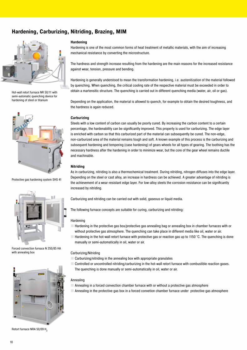
Hardening, Carburizing, Nitriding, Brazing, MIM
HardeningHardening is one of the most common forms of heat treatment of metallic materials, with the aim of increasing mechanical resistance by converting the microstructure.
The hardness and strength increase resulting from the hardening are the main reasons for the increased resistance against wear, tension, pressure and bending.
Hardening is generally understood to mean the transformation hardening, i.e. austenitization of the material followed by quenching. When quenching, the critical cooling rate of the respective material must be exceeded in order to obtain a martensitic structure. The quenching is carried out in different quenching media (water, air, oil or gas).
Depending on the application, the material is allowed to quench, for example to obtain the desired toughness, and the hardness is again reduced.
CarburizingSteels with a low content of carbon can usually be poorly cured. By increasing the carbon content to a certain percentage, the hardenability can be significantly improved. This property is used for carburizing. The edge layer is enriched with carbon so that this carburized part of the material can subsequently be cured. The non-edge, non-carburized area of the material remains tough and soft. A known example of this process is the carburizing and subsequent hardening and tempering (case hardening) of gears wheels for all types of gearing. The toothing has the necessary hardness after the hardening in order to minimize wear, but the core of the gear wheel remains ductile and machinable.
NitridingAs in carburizing, nitriding is also a thermochemical treatment. During nitriding, nitrogen diffuses into the edge layer. Depending on the steel or cast alloy, an increase in hardness can be achieved. A greater advantage of nitriding is the achievement of a wear-resistant edge layer. For low-alloy steels the corrosion resistance can be significantly increased by nitriding.
Carburizing and nitriding can be carried out with solid, gaseous or liquid media.
The following furnace concepts are suitable for curing, carburizing and nitriding:
Hardening � Hardening in the protective gas box/protective gas annealing bag or annealing box in chamber furnaces with or without protective gas atmosphere. The quenching can take place in different media like oil, water or air. � Hardening in the hot-wall retort furnace with protective gas or reaction gas up to 1150 °C. The quenching is done manually or semi-automatically in oil, water or air.
Carburizing/Nitriding � Carburizing/nitriding in the annealing box with appropriate granulates � Controlled or uncontrolled nitriding/carburizing in the hot-wall retort furnace with combustible reaction gases. The quenching is done manually or semi-automatically in oil, water or air.
Annealing � Annealing in a forced convection chamber furnace with or without a protective gas atmosphere � Annealing in the protective gas box in a forced convetion chamber furnace under protective gas atmosphere
Hot-wall retort furnace NR 50/11 with semi-automatic quenching device for hardening of steel or titanium
Protective gas hardening system SHS 41
Forced convection furnace N 250/85 HA with annealing box
Retort furnace NRA 50/09 H2
10
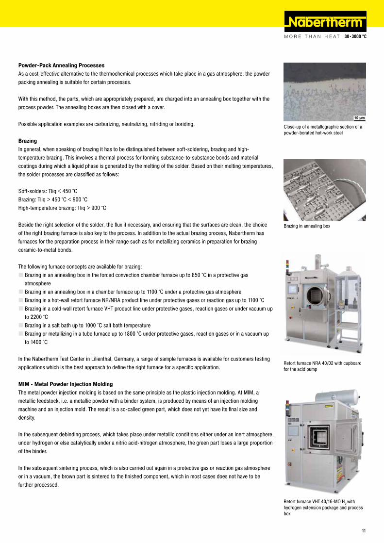
Powder-Pack Annealing ProcessesAs a cost-effective alternative to the thermochemical processes which take place in a gas atmosphere, the powder packing annealing is suitable for certain processes.
With this method, the parts, which are appropriately prepared, are charged into an annealing box together with the process powder. The annealing boxes are then closed with a cover.
Possible application examples are carburizing, neutralizing, nitriding or boriding.
BrazingIn general, when speaking of brazing it has to be distinguished between soft-soldering, brazing and high-temperature brazing. This involves a thermal process for forming substance-to-substance bonds and material coatings during which a liquid phase is generated by the melting of the solder. Based on their melting temperatures, the solder processes are classified as follows:
Soft-solders: Tliq < 450 °CBrazing: Tliq > 450 °C < 900 °CHigh-temperature brazing: Tliq > 900 °C
Beside the right selection of the solder, the flux if necessary, and ensuring that the surfaces are clean, the choice of the right brazing furnace is also key to the process. In addition to the actual brazing process, Nabertherm has furnaces for the preparation process in their range such as for metallizing ceramics in preparation for brazing ceramic-to-metal bonds.
The following furnace concepts are available for brazing: � Brazing in an annealing box in the forced convection chamber furnace up to 850 °C in a protective gas atmosphere � Brazing in an annealing box in a chamber furnace up to 1100 °C under a protective gas atmosphere � Brazing in a hot-wall retort furnace NR/NRA product line under protective gases or reaction gas up to 1100 °C � Brazing in a cold-wall retort furnace VHT product line under protective gases, reaction gases or under vacuum up to 2200 °C � Brazing in a salt bath up to 1000 °C salt bath temperature � Brazing or metallizing in a tube furnace up to 1800 °C under protective gases, reaction gases or in a vacuum up to 1400 °C
In the Nabertherm Test Center in Lilienthal, Germany, a range of sample furnaces is available for customers testing applications which is the best approach to define the right furnace for a specific application.
MIM - Metal Powder Injection MoldingThe metal powder injection molding is based on the same principle as the plastic injection molding. At MIM, a metallic feedstock, i.e. a metallic powder with a binder system, is produced by means of an injection molding machine and an injection mold. The result is a so-called green part, which does not yet have its final size and density.
In the subsequent debinding process, which takes place under metallic conditions either under an inert atmosphere, under hydrogen or else catalytically under a nitric acid-nitrogen atmosphere, the green part loses a large proportion of the binder.
In the subsequent sintering process, which is also carried out again in a protective gas or reaction gas atmosphere or in a vacuum, the brown part is sintered to the finished component, which in most cases does not have to be further processed.
Brazing in annealing box
Close-up of a metallographic section of a powder-borated hot-work steel
Retort furnace VHT 40/16-MO H2 with hydrogen extension package and process box
Retort furnace NRA 40/02 with cupboard for the acid pump
11

Additive manufacturing allows for the direct conversion of design construction files fully functional objects. With 3D-printing objects from metals, plastics, ceramics, glass, sand or other materials are built-up in layers until they have reached their final shape.
Depending on the material, the layers are interconnected by means of a binder system or by laser technology.
Many methods of additive manufacturing require subsequent heat treatment of the manufactured components. The requirements for the furnaces for heat treatment depend on the component material, the working temperature, the atmosphere in the furnace and, of course, the additive production process.
Nabertherm offers solutions from curing for conservation of the green strength up to sintering in vacuum furnaces in which the objects of metal are annealed or sintered.
Also, concomitant or upstream processes of additive manufacturing require the use of a furnace in order to achieve the desired product properties, such as heat treatment or drying the powder.
Retort furnace NR 150/11 for annealing of metal parts of 3D-printing
Oven TR 240 for drying of powders
Chamber oven KTR 2000 for curing after 3D-printing
Compact tube furnace for sintering or annealing under protective gases or in a vacuum after 3D-printing
HT 160/17 DB200 for debinding and sinte-ring of ceramics after 3D-printing
Additive Manufacturing, 3D-Printing
Metals
DebindingSintering
Stress-relievingSolution annealing
Hardening
Chamber furnaces with protective gas boxes
Ceramics, Glass, Composites, Sand
Plastics
DebindingSintering
DryingCuring
CuringTempering
Drying
under Protective Gases, Reaction Gases or in Vacuum
in Air in Air
Hot-wall retort furnaces
Cold-wall retort furnaces
Debinding in chamber furnaces with air circulation
Sintering in chamber furnaces Debinding and Sintering in combi
furnacesDewaxing Furnaces
See also concepts for drying, debinding, thermal cleaning and wax burnout in catalog Advanced
Materials
OvensChamber dryers
Forced convection chamber furnaces
See als concepts for drying, debinding, thermal cleaning and wax burnout in catalog Advanced
Materials as well as catalog Thermal Process Technology I
12

In additive manufacturing, a distinction is made between printing with and without binder. Depending on the manufacturing process, different furnace types are used for the subsequent heat treatment.
Apart from the factors described above, the previous processes from the heat treatment also have an influence on the overall result. One important criteria for a good surface quality is that the components are cleaned properly before the heat treatment.
This also applies to processes that are carried out in vacuum or in furnaces where a low residual oxygen concentration is important. For these furnaces, it is important that they are cleaned and maintained regularly. Even the smallest leak or contamination can produce an unsatisfactory result.
Binder-Free Systems
In binder-free additive manufacturing, in most cases, the components are produced in a laser melting process.
The tables below show typical materials and construction platform sizes of laser-based systems that are available on the market with suggestions with respect to furnace sizes, required temperature and atmosphere in the furnace.
Aluminum ComponentsGenerally, aluminum is heat treated in air at temperatures between 150 °C and 450 °C.
Due to the very good temperature uniformity, forced convection chamber furnaces are suitable for processes such as tempering, aging, stress-reliefing or preheating.
Examples for max Forced convection chamber furnaces, see page 60platform sizes up to 450 °C1
210 x 210 mm NA 30/45280 x 280 mm NA 60/45360 x 360 mm NA 120/45480 x 480 mm NA 250/45600 x 600 mm NA 500/45
1Also available for 650 °C and 850 °C
Stainless Steel and Titanium ComponentsIn many cases, certain stainless steels and titanium are heat treated in a protective gas atmosphere at temperatures below 850 °C.
By using a protective gas box with the corresponding process gas supply, a standard furnace can be upgraded to a protective gas furnace. Depending on the type of process gas, the preflushing rate, the process flushing rate, and the condition of the box, it is possible to achieve residual oxygen concentrations of up to 100 ppm.
The forced convection chamber furnaces with protective gas boxes described below have a working temperature range between 150 °C and 850 °C. If the protective gas boxes are removed from the furnace, aluminum components can also be heat treated in air.
Examples for Forced convection chamber furnaces, see page 60platform sizes up to 850 °C with protective gas box100 x 100 mm N 30/85 HA200 x 200 mm N 60/85 HA280 x 280 mm N 120/85 HA400 x 400 mm N 250/85 HA550 x 550 mm N 500/85 HA
Printed aluminum part, heat treated in model N 250/85 HA (Manufacturer CETIM CERTEC on SUPCHAD platform)
Forced convection chamber furnace NA 250/45 for heat treatment in air
Forced convection chamber furnace N 250/85 HA with protective gas box for heat treatment in a protective gas atmosphere
13

Inconel or Cobalt chromium ComponentsMaterials such as Inconel and cobalt-chromium are generally heat treated at temperatures from 850 °C up to between 1100 °C and 1150 °C. Various furnace families are used for these processes. In many cases, the chamber furnaces of the LH .. or NW .. series with protective gas boxes are sufficient to provide an outstanding price/performance ratio. Both furnace groups are suitable for temperatures between 800 °C and 1100 °C.
Examples for Chamber furnaces see page 54 and 58platform sizes up to 1100 °C with protective gas box100 x 100 mm LH 30/12250 x 250 mm LH 120/12400 x 400 mm LH 216/12420 x 520 mm NW 440400 x 800mm NW 660
Cold-wall retort furnaces are used for processes in protective gas at temperatures above 1100 °C or under vacuum above 600 °C.
Examples for Cold-wall retort furnacesplatform sizes see page 26100 x 100 mm VHT 8/12-MO250 x 250 mm VHT 40/12-MO400 x 400 mm VHT 100/12-MO
With sensitive materials, such as titanium, the component may still oxidize due to the residual oxygen concentration in the protective gas box.
In these cases, hot-wall retort furnaces with a maximum temperature of 950 °C or 1100 °C are used. These gas tight retort furnaces are ideal for heat treatment processes that require a defined protective or reaction gas atmosphere. The compact models can also be designed for heat treatment under vacuum up to 600 °C. The risk of oxidation on the component is considerably reduced with these furnaces.
Examples for Hot-wall retort furnacesplatform sizes see page 16180 x 180 mm NR(A) 17/..280 x 280 mm NR(A) 50/..400 x 400 mm NR(A) 150/..
Titanium rods after heat treatment in NR 50/11 in argon atmosphere
Chamber furnace LH 60/12 with protective gas box for heat treatment in a protective gas atmosphere
Hot-wall retort furnace NRA 150/09 for heat treatment in a protective gas atmosphere
Cold-wall retort furnace VHT 100/12-MO for processes in high vacuum
14

Systems with Binder
In 3D printing, organic binders, which evaporate during heat treatment, are used to build-up the part. The printed parts can be made of ceramic, metal, glass or sand. Depending on the evaporation volume, furnaces with graduated safety systems for debinding and sintering are used.
Debinding and Sintering in AirThis table shows examples of furnaces with the respective safety technology for debinding in air and the corresponding sintering furnaces for high temperatures, which are suitable, for example, for sintering many oxide ceramics.
Printing dimensions up to Debinding furnaces1 Sintering furnaces2
see catalog Advanced Materials see catalog Advanced Materials100 x 100 x 100 mm L 9/11 BO LHT 4/16200 x 200 x 150 mm L 9/11 BO HT 40/16300 x 400 x 150 mm L 40/11 BO HT 64/17
1 Values for debinding like max. organic content, or evaporation rate have to be considered2The furnaces are available with different max. furnace chamber temperatures
Printing dimensions up to Hot-wall retort furnaces1 Cold-wall retort furnaces2
see page 16 see page 26150 x 150 x 150 mm NRA 17/09 VHT 8/16-MO300 x 300 x 300 mm NRA 50/09 VHT 40/16-MO400 x 400 x 400 mm NRA 150/09 VHT 100/16-MO
1Safety systems see page 182Parts without residual binder. In case of a low content of residual binder we recommend an inner process chamber.
Debinding and Sintering in Protective or Reaction Gas or under VacuumTo protect metal components that were printed using a binder-based system against oxidation, two process steps, debinding and sintering, are carried out in an oxygen-free atmosphere.
Depending on the material and the binder system, debinding is carried out either in a non-flammable protective gas (IDB), under hydrogen (H2), or catalytically in a mixture of nitric acid and nitrogen. Adapted safety systems are used to ensure the safety of these processes.
The table contains examples of furnaces which can be equipped with suitable safety technology. Hot-wall retort furnaces are used as debinding furnaces and cold-wall retort furnaces as sintering furnaces. Under certain circumstances, depending on the application, it is possible to use the same furnace for both processes.
The models listed in the table above are just a few examples.
Muffle furnace L 40/11 BO with passive safety system and integrated post combustion for thermal debinding in air
High-temperature furnace HT 64/17 DB100 with passive safety system for debinding and sintering in air
15

These gas tight retort furnaces are equipped with direct or indirect heating depending on temperature. They are perfectly suited for various heat treatment processes requiring a defined protective or a reaction gas atmosphere. These compact models can also be laid out for heat treatment under vacuum up to 600 °C. The furnace chamber consists of a gas tight retort with water cooling around the door to protect the special sealing. With the corresponding safety technology, retort furnaces are also suitable for applications under reaction gases, such as hydrogen or, in combination with the IDB package, for inert debinding or for pyrolysis processes.
Hot-Wall Retort Furnaces up to 1100 °C
Inside heating in retort furnace NRA ../06
Schematic presentation of a hot-wall retort furnace with additional equipment
1 Retort2 Heating3 Insulation4 Gas management system5 Vacuum pump6 Fan for indirect cooling7 Outlet indirect cooling8 Exhaust torch9 Fan for gas circulation (NRA models)10 Charging frame11 Emergency flushing container
Different model versions are available depending on the temperature range :
Models NRA ../06 with Tmax 650 °C � Heating elements located inside the retort � Temperature uniformity up to +/- 5 °C inside the work space see page 84 � Retort made of 1.4571 � Gas circulation fan in the back of the retort provides for optimal temperature uniformity � Insulation made of mineral wool
Models NRA ../09 with Tmax 950 °CDesign like models NRA ../06 with following differences:
� Outside heating with heating elements around the retort � Retort made of 1.4828 � Multi-layer insulation made of fiber materials classified as non-carcinogenic
Models NR ../11 with Tmax 1100 °CDesign like models NRA ../09 with following differences:
� Retort made of 1.4841 �Without gas-circulation
Short and long-term durability of retort materials
Tens
ion
[MPa
]
Temperature [°C]
Material 1Material 2Material 3
16

Vacuum pump for cold evacuation of the retort
Process control H3700 for automatic version
Basic version � Compact housing in frame design with removable stainless steel sheets � Controls and gas supply integrated in the furnace housing �Welded charging supports in the retort resp. air-baffle box in the furnaces with atmosphere circulation � Swivel door hinged on right side � Open cooling water system � Depending on furnace volume for 950 °C- and 1100 °C-models the control system is divided in one or more heating zones � Furnace temperature control with measurement outside the retort � Gas supply system for one non-flammable protective or reaction gas with flow meter and magnetic valve � Port for vacuum pump for cold evacuation � Operation under vacuum up to 600 °C with optional vacuum pumps � Defined application within the constraints of the operating instructions � NTLog Basic for Nabertherm controller: recording of process data with USB-flash drive � Controls description see page 88
Additional equipment � Upgrade for other non-flammable gases, H2 version for flammable gases see page 18 � Automatic gas injection, including MFC flow controller for alternating volume flow, controlled with process control H3700, H1700 � Vacuum pump for evacuating of the retort up to 600 °C, attainable vacuum up to 10-5 mbar subject to selected pump � Indirect cooling see page 33 � Direct cooling see page 33 � Heat exchanger with closed-loop cooling water circuit for door cooling � Measuring device for residual oxygen content � Door heating � Temperature control as charge control with temperature measurement inside and outside the retort � Retort, made of 2.4633 for Tmax 1150 °C � Process control and documentation via VCD software package or Nabertherm Control Center (NCC) for monitoring, documentation and control see page 88
Retort furnace NRA 150/09 with controls H1700 and bayonet door lock
Retort furnace NRA 25/09
17

H2 Version for Operation with Flammable Process GasesWhen a flammable process gas like hydrogen is used, the retort furnace is additionally equipped with the required safety technology. Only certified and industry proven safety sensors are used. The furnace is controlled by a fail-safe PLC control system (S7- 300F/safety controller).
� Supply of flammable process gas at controlled overpressure of 50 mbar relative � Certified safety concept � PLC controls with graphic touch panel H3700 for data input � Redundant gas inlet valves for hydrogen � Monitored pre-pressures of all process gases � Bypass for safe flushing of furnace chamber with inert gas � Torch for thermal post combustion of exhaust gases � Emergency flood container for purging the furnace in case of failore
Hot-Wall Retort Furnaces up to 1100 °C
Model Tmax Model Tmax Work space dimensions in mm Useful volume Electrical°C °C w d h in l connection*
NRA 17/.. 650 or 950 NR 17/11 1100 225 350 225 17 3-phaseNRA 25/.. 650 or 950 NR 25/11 1100 225 500 225 25 3-phaseNRA 50/.. 650 or 950 NR 50/11 1100 325 475 325 50 3-phaseNRA 75/.. 650 or 950 NR 75/11 1100 325 700 325 75 3-phaseNRA 150/.. 650 or 950 NR 150/11 1100 450 750 450 150 3-phaseNRA 200/.. 650 or 950 NR 200/11 1100 450 1000 450 200 3-phaseNRA 300/.. 650 or 950 NR 300/11 1100 590 900 590 300 3-phaseNRA 400/.. 650 or 950 NR 400/11 1100 590 1250 590 400 3-phaseNRA 500/.. 650 or 950 NR 500/11 1100 720 1000 720 500 3-phaseNRA 700/.. 650 or 950 NR 700/11 1100 720 1350 720 700 3-phaseNRA 1000/.. 650 or 950 NR 1000/11 1100 870 1350 870 1000 3-phase
*Please see page 89 for more information about supply voltage
IDB Version for Debinding under Non-flammable Protective Gases or for Pyrolysis ProcessesThe retort furnaces of the NR and NRA product line are perfectly suited for debinding under non-flammable protective gases or for pyrolysis processes. The IDB version of the retort furnaces implements a safety concept by controlled inerting the furnace chamber with a protective gas. Exhaust gases are burned in a termal post combustion. Both the purging and the torch function are monitored to ensure a safe operation.
Retort furnace NRA 300/09 H2 for heat treatment under hydrogen
Charging of the retort furnace NRA 300/06 with a pallet truck
Retort furnace NRA 400/03 IDB with thermal post combustion system
� Process control under monitored overpressure � Process control H1700 with PLC controls and graphic touch panel for data input � Monitored gas pre-pressure of the process gas � Bypass for safe flushing of furnace chamber with inert gas � Thermal post combustion of exhaust gases
18

With their high level of flexibility and innovation, Nabertherm offers the optimal solution for customer-specific applications.
Based on our standard models, we develop individual solutions also for integration in overriding process systems. The solutions shown on this page are just a few examples of what is feasible. From working under vacuum or protective gas via innovative control and automation technology for a wide selection of temperatures, sizes, lenghts and other properties of retort furnaces – we will find the appropriate solution for a suitable process optimization.
Hot-wall retor furnace NRA 1700/06 with chargin frame. For grey room/clean room installation for heat treatment of glass under protective gases.
Hot-wall retort furnace NRA 1700/06 for steel annealing under nitrogen
Hot-wall retort furnace NRA 3300/06 with automatic door opening for the integration in a fully automatic quench & temper plant
19

Manual or Semi-Automatic Tempering Plants for Hardening in Protective Gas with Subsequent Quenching outside the Furnace
Semi-automatic annealing plant with retort furnace NR 50/11 and water quenching bath on rails
Processes such as hardening of titanium or hardening/carburization, carburizing of steel, which require a controlled gas atmosphere with a subsequent quenching process, can be carried out with protective gas quenching and tempering plants. Such a system consists of a hot-wall retort furnace and an external quenching bath. Depending on the arrangement and design of the components, quenching delay times of up to 10 seconds can be achieved, so that the components are exposed to air for a short time only.
Chamber retort furnaces or pit-type retort furnaces can be offered for heavy components, where the batch is removed by crane after heat treatment and transferred to the quenching bath.
Depending on the requirements, the degree of automation can range from a purely manual version to a fully automated system with manipulator.
The quenching medium shall be selected taking into account the material to be treated and may be water, polymer, oil or a salt.
Additional equipment required for the process, such as cooling or heating or circulation of the medium, can be offered as well.
In a manual quenching and tempering plant, the process control is carried out by means of a Nabertherm controller. For more complex requirements, the controller is replaced by a PLC control. Process documentation in accordance with current standards such as the AMS 2750 E (NADCAP) is also possible.
NR 50/11 with charging rack for manual re-moval at high temperatures for quenching in an external bath
20
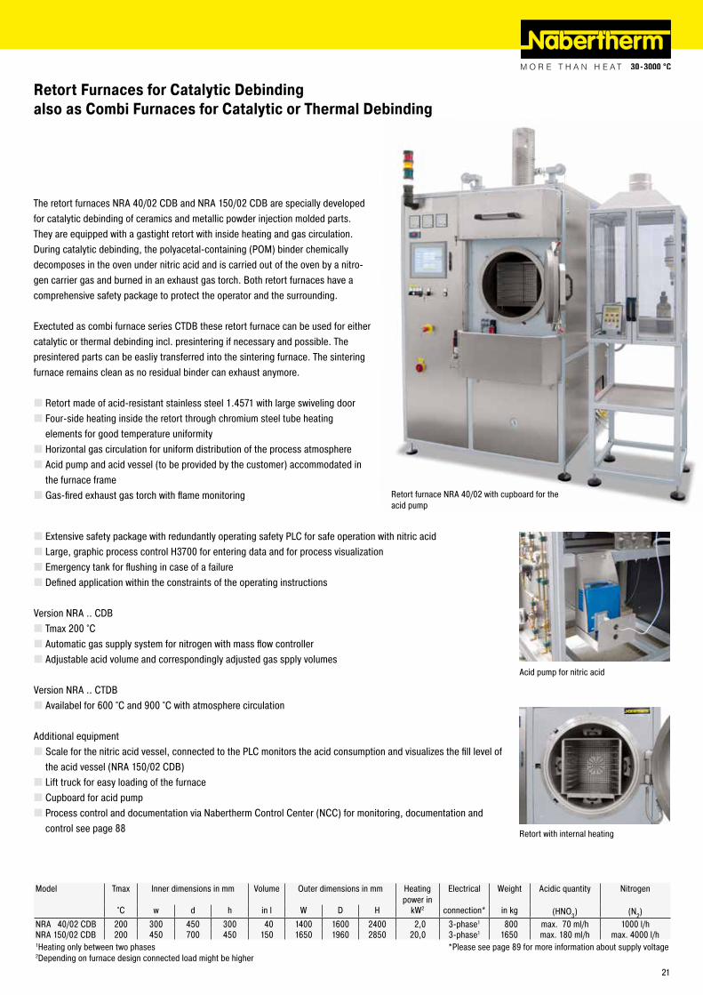
Retort Furnaces for Catalytic Debinding also as Combi Furnaces for Catalytic or Thermal Debinding
The retort furnaces NRA 40/02 CDB and NRA 150/02 CDB are specially developed for catalytic debinding of ceramics and metallic powder injection molded parts. They are equipped with a gastight retort with inside heating and gas circulation. During catalytic debinding, the polyacetal-containing (POM) binder chemically decomposes in the oven under nitric acid and is carried out of the oven by a nitro-gen carrier gas and burned in an exhaust gas torch. Both retort furnaces have a comprehensive safety package to protect the operator and the surrounding.
Exectuted as combi furnace series CTDB these retort furnace can be used for either catalytic or thermal debinding incl. presintering if necessary and possible. The presintered parts can be easliy transferred into the sintering furnace. The sintering furnace remains clean as no residual binder can exhaust anymore.
� Retort made of acid-resistant stainless steel 1.4571 with large swiveling door � Four-side heating inside the retort through chromium steel tube heating elements for good temperature uniformity � Horizontal gas circulation for uniform distribution of the process atmosphere � Acid pump and acid vessel (to be provided by the customer) accommodated in the furnace frame � Gas-fired exhaust gas torch with flame monitoring
Acid pump for nitric acid
Retort with internal heating
Model Tmax Inner dimensions in mm Volume Outer dimensions in mm Heating power in
Electrical Weight Acidic quantity Nitrogen
°C w d h in l W D H kW2 connection* in kg (HNO3) (N2)NRA 40/02 CDB 200 300 450 300 40 1400 1600 2400 2,0 3-phase1 800 max. 70 ml/h 1000 l/hNRA 150/02 CDB 200 450 700 450 150 1650 1960 2850 20,0 3-phase1 1650 max. 180 ml/h max. 4000 l/h1Heating only between two phases *Please see page 89 for more information about supply voltage2Depending on furnace design connected load might be higher
Retort furnace NRA 40/02 with cupboard for the acid pump
� Extensive safety package with redundantly operating safety PLC for safe operation with nitric acid � Large, graphic process control H3700 for entering data and for process visualization � Emergency tank for flushing in case of a failure � Defined application within the constraints of the operating instructions
Version NRA .. CDB � Tmax 200 °C � Automatic gas supply system for nitrogen with mass flow controller � Adjustable acid volume and correspondingly adjusted gas spply volumes
Version NRA .. CTDB � Availabel for 600 °C and 900 °C with atmosphere circulation
Additional equipment � Scale for the nitric acid vessel, connected to the PLC monitors the acid consumption and visualizes the fill level of the acid vessel (NRA 150/02 CDB) � Lift truck for easy loading of the furnace � Cupboard for acid pump � Process control and documentation via Nabertherm Control Center (NCC) for monitoring, documentation and control see page 88
21
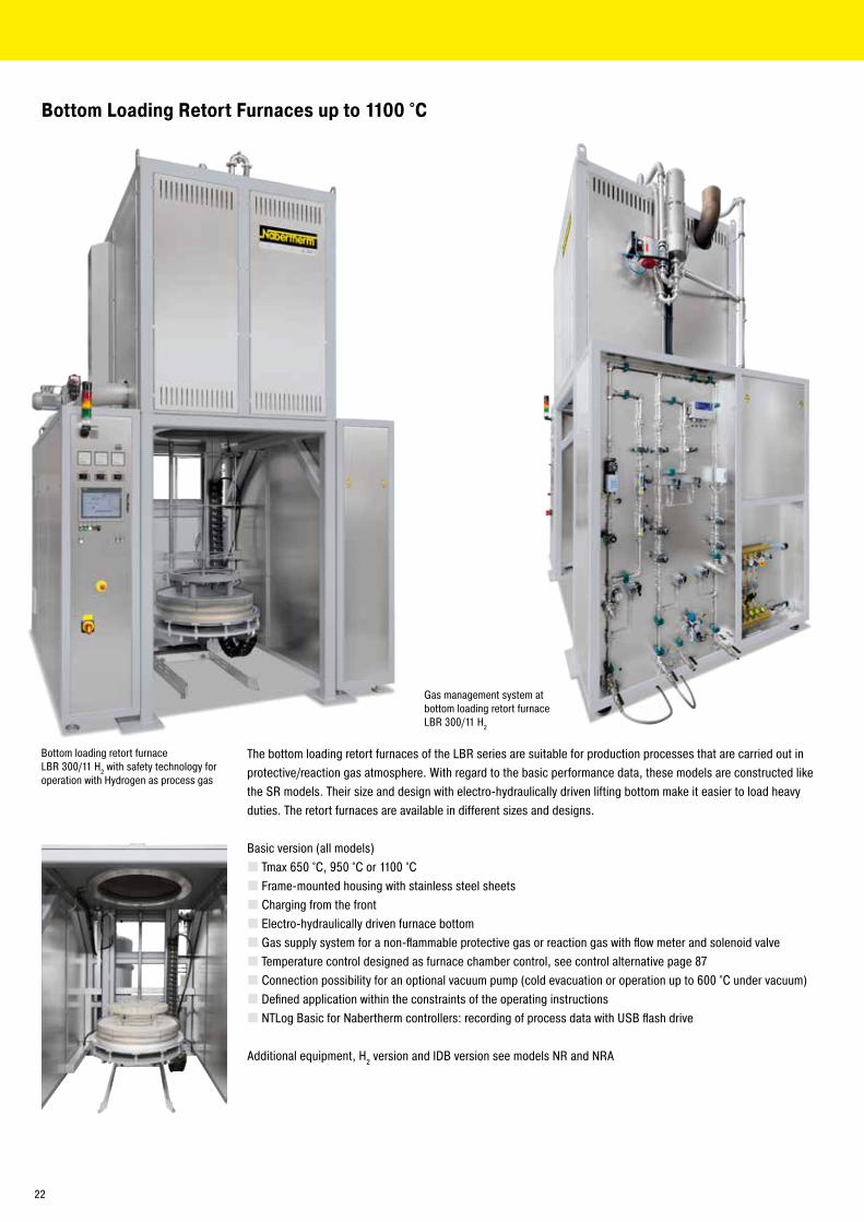
Bottom loading retort furnace LBR 300/11 H2 with safety technology for operation with Hydrogen as process gas
Gas management system at bottom loading retort furnace LBR 300/11 H2
Bottom Loading Retort Furnaces up to 1100 °C
The bottom loading retort furnaces of the LBR series are suitable for production processes that are carried out in protective/reaction gas atmosphere. With regard to the basic performance data, these models are constructed like the SR models. Their size and design with electro-hydraulically driven lifting bottom make it easier to load heavy duties. The retort furnaces are available in different sizes and designs.
Basic version (all models) � Tmax 650 °C, 950 °C or 1100 °C � Frame-mounted housing with stainless steel sheets � Charging from the front � Electro-hydraulically driven furnace bottom � Gas supply system for a non-flammable protective gas or reaction gas with flow meter and solenoid valve � Temperature control designed as furnace chamber control, see control alternative page 87 � Connection possibility for an optional vacuum pump (cold evacuation or operation up to 600 °C under vacuum) � Defined application within the constraints of the operating instructions � NTLog Basic for Nabertherm controllers: recording of process data with USB flash drive
Additional equipment, H2 version and IDB version see models NR and NRA
22
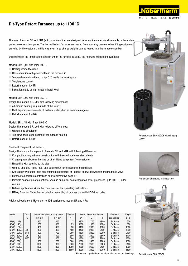
The retort furnaces SR and SRA (with gas circulation) are designed for operation under non-flammable or flammable protective or reaction gases. The hot-wall retort furnaces are loaded from above by crane or other lifting equipment provided by the customer. In this way, even large charge weights can be loaded into the furnace chamber.
Depending on the temperature range in which the furnace be used, the following models are available:
Models SRA ../06 with Tmax 600 °C � Heating inside the retort � Gas-circulation with powerful fan in the furnace lid � Temperature uniformity up to +/- 5 °C inside the work space � Single-zone control � Retort made of 1.4571 � Insulation made of high-grade mineral wool
Models SRA ../09 with Tmax 950 °CDesign like models SR…/06 with following differences:
� All-around heating from outside of the retort � Multi-layer insulation made of materials, classified as non-carcinogenic � Retort made of 1.4828
Models SR .../11 with Tmax 1100 °CDesign like models SR…/09 with following differences:
�Without gas-circulation � Top down multi-zone control of the furnace heating � Retort made of 1.4841
Standard Equipment (all models)Design like standard equipment of models NR and NRA with following differences:
� Compact housing in frame construction with inserted stainless steel sheets � Charging from above with crane or other lifting equipment from customer � Hinged lid with opening to the side �Welded charging frame resp. gas-guiding box for furnaces with circulation � Gas-supply system for one non-flammable protective or reactive gas with flowmeter and magnetic valve � Furnace temperature control see control alternative page 87 � Possible connection of an optional vacuum pump (for cold evacuation or for processes up to 600 °C under vacuum) � Defined application within the constraints of the operating instructions � NTLog Basic for Nabertherm controller: recording of process data with USB-flash drive
Additional equipment, H2 version or IDB version see models NR and NRA
Model Tmax Inner dimensions of alloy retort Volume Outer dimensions in mm Electrical Weight°C Ø in mm h in mm in l W D H connection* in kg
SR(A) 17/.. 250 350 17 1300 1700 1800 3-phase 600SR(A) 25/.. 250 500 25 1300 1900 1800 3-phase 800SR(A) 50/.. 400 450 50 1400 2000 1800 3-phase 1300SR(A) 100/.. 600, 400 800 100 1400 2000 2100 3-phase 1500SR(A) 200/.. 950 600 700 200 1600 2200 2200 3-phase 2100SR(A) 300/.. or 600 1000 300 1600 2200 2500 3-phase 2400SR(A) 500/.. 1100 800 1000 500 1800 2400 2700 3-phase 2800SR(A) 600/.. 800 1200 600 1800 2400 2900 3-phase 3000SR(A) 800/.. 1000 1000 800 2000 2600 2800 3-phase 3100SR(A) 1000/.. 1000 1300 1000 2000 2600 3100 3-phase 3300SR(A) 1500/.. 1200 1300 1500 2200 2800 3300 3-phase 3500
*Please see page 89 for more information about supply voltage
Retort furnace SRA 300/06 with charging basket
Front made of textured stainless steel
Retort furnace SRA 200/09
Pit-Type Retort Furnaces up to 1100 °C
23
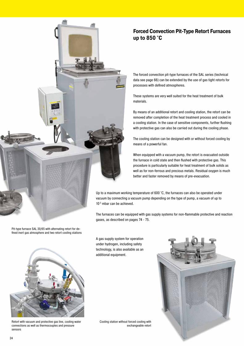
Pit-type furnace SAL 30/65 with alternating retort for de-fined inert gas atmosphere and two retort cooling stations
Forced Convection Pit-Type Retort Furnaces up to 850 °C
Cooling station without forced cooling with exchangeable retort
Retort with vacuum and protective gas line, cooling water connections as well as thermocouples and pressure sensors
The forced convection pit-type furnaces of the SAL series (technical data see page 66) can be extended by the use of gas tight retorts for processes with defined atmospheres.
These systems are very well suited for the heat treatment of bulk materials.
By means of an additional retort and cooling station, the retort can be removed after completion of the heat treatment process and cooled in a cooling station. In the case of sensitive components, further flushing with protective gas can also be carried out during the cooling phase.
The cooling station can be designed with or without forced cooling by means of a powerful fan.
When equipped with a vacuum pump, the retort is evacuated outside the furnace in cold state and then flushed with protective gas. This procedure is particularly suitable for heat treatment of bulk solids as well as for non-ferrous and precious metals. Residual oxygen is much better and faster removed by means of pre-evacuation.
Up to a maximum working temperature of 600 °C, the furnaces can also be operated under vacuum by connecting a vacuum pump depending on the type of pump, a vacuum of up to 10-5 mbar can be achieved.
The furnaces can be equipped with gas supply systems for non-flammable protective and reaction gases, as described on pages 74 - 75.
A gas supply system for operation under hydrogen, including safety technology, is also available as an additional equipment.
24
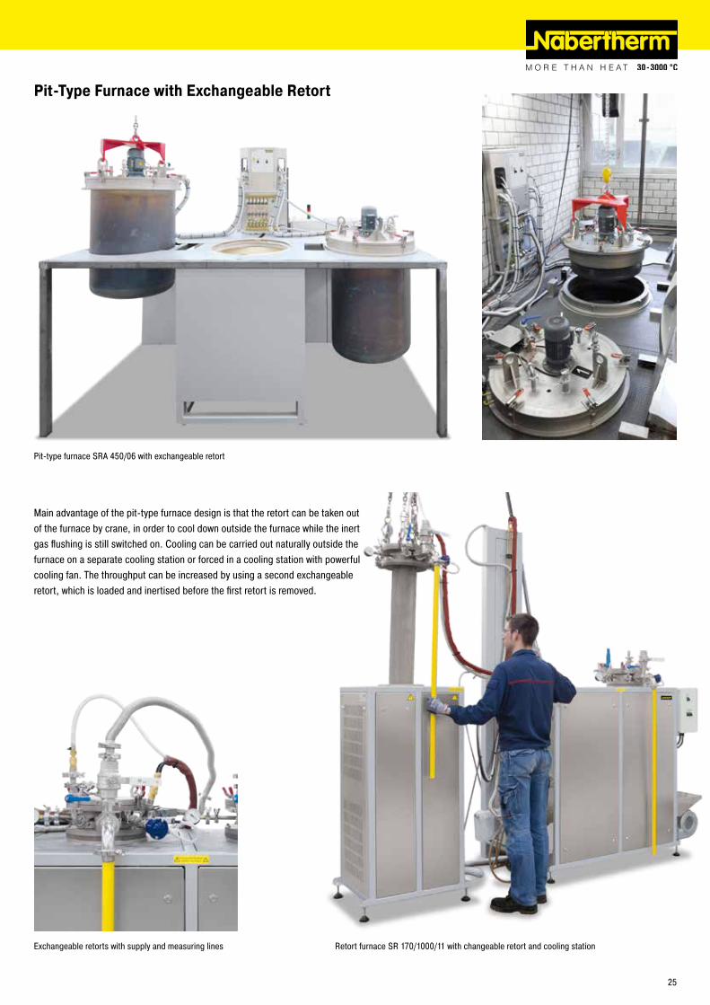
Retort furnace SR 170/1000/11 with changeable retort and cooling station
Pit-Type Furnace with Exchangeable Retort
Pit-type furnace SRA 450/06 with exchangeable retort
Main advantage of the pit-type furnace design is that the retort can be taken out of the furnace by crane, in order to cool down outside the furnace while the inert gas flushing is still switched on. Cooling can be carried out naturally outside the furnace on a separate cooling station or forced in a cooling station with powerful cooling fan. The throughput can be increased by using a second exchangeable retort, which is loaded and inertised before the first retort is removed.
Exchangeable retorts with supply and measuring lines
25
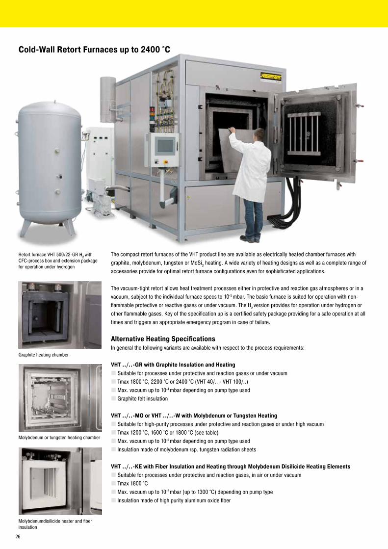
The compact retort furnaces of the VHT product line are available as electrically heated chamber furnaces with graphite, molybdenum, tungsten or MoSi2 heating. A wide variety of heating designs as well as a complete range of accessories provide for optimal retort furnace configurations even for sophisticated applications.
The vacuum-tight retort allows heat treatment processes either in protective and reaction gas atmospheres or in a vacuum, subject to the individual furnace specs to 10-5 mbar. The basic furnace is suited for operation with non-flammable protective or reactive gases or under vacuum. The H2 version provides for operation under hydrogen or other flammable gases. Key of the specification up is a certified safety package providing for a safe operation at all times and triggers an appropriate emergency program in case of failure.
Alternative Heating SpecificationsIn general the following variants are available with respect to the process requirements:
VHT ../..-GR with Graphite Insulation and Heating � Suitable for processes under protective and reaction gases or under vacuum � Tmax 1800 °C, 2200 °C or 2400 °C (VHT 40/.. - VHT 100/..) � Max. vacuum up to 10-4 mbar depending on pump type used � Graphite felt insulation
VHT ../..-MO or VHT ../..-W with Molybdenum or Tungsten Heating � Suitable for high-purity processes under protective and reaction gases or under high vacuum � Tmax 1200 °C, 1600 °C or 1800 °C (see table) � Max. vacuum up to 10-5 mbar depending on pump type used � Insulation made of molybdenum rsp. tungsten radiation sheets
VHT ../..-KE with Fiber Insulation and Heating through Molybdenum Disilicide Heating Elements � Suitable for processes under protective and reaction gases, in air or under vacuum � Tmax 1800 °C � Max. vacuum up to 10-2 mbar (up to 1300 °C) depending on pump type � Insulation made of high purity aluminum oxide fiber
Cold-Wall Retort Furnaces up to 2400 °C
Retort furnace VHT 500/22-GR H2 with CFC-process box and extension package for operation under hydrogen
Graphite heating chamber
Molybdenumdisilicide heater and fiber insulation
Molybdenum or tungsten heating chamber
26

Basic version � Standard furnace sizes 8 - 500 liters �Water-cooled retort made of stainless steel � Frame made of stable steel profiles, easy to service due to easily removable stainless steel panels � Housing of the VHT 8 model on castors for easy repositioning of furnace � Cooling water manifold with manual tap, automatic flow monitoring, open-loop cooling water system � Adjustable cooling water circuits with flowmeter and temperature indicator and overtemperature protection � Switchgear and controller integrated in furnace housing � Process control with controller P470 � Over-temperature limiter with adjustable cutout temperature for thermal protection class 2 in accordance with EN 60519-2 � Manual operation of the process gas and vacuum functions � Manual gas supply for one process gas (N2, Ar or non-flammable forming gas) with adjustable flow � Bypass with manual valve for rapid filling or flooding of furnace chamber � Manual gas outlet with overflow valve (20 mbar relative) for over-pressure operation � Single-stage rotary vane pump with ball valve for pre-evacuating and heat treatment in a rough vacuum to 5 mbar � Pressure gauge for visual pressure monitoring � Defined application within the constraints of the operating instructions
Retort furnace VHT 8/16-MO with automa-tion package
Retort furnace VHT 100/16-MO with auto-mation package
Schematic presentation of a cold-wall retort furnace with additional equipment
1 Retort2 Heating3 Insulation4 Gas management system5 Vacuum pump6 Cooling water distribution7 Controls8 Integrated switchgear9 Heating transformer10 Charging frame inside the inner process chamber
27

Additional equipment housing/heater � Housing, optionally divisible, for passing through narrow door frames (VHT 8) � Lift door � Individual heating concepts
Additional equipment gas management system � Manual gas supply for second process gas (N2, Ar or non-flammable forming gas) with adjustable flow and bypass � Mass flow controller for alternating volume flow and generation of gas mixtures with second process gas (only with automation package) � Inner process box made of molybdenum, tungsten, graphite or CFC, especially recommended for debinding processes. The box is installed in the furnace with direct gas inlet and outlet and provides for better temperature uniformity. Generated exhaust gases will be directly lead out the inner process chamber during debinding. The change of gas inlet pathes after debinding results in a clean process gas atmosphere during sintering.
Retort furnace VHT 40/22-GR with motor-driven lift door and front frame for connection to a glovebox
Heat treatment of copper bars under hydrogen in retort furnace VHT 8/16-MO
Thermocouple, type S with automatic pull-out device for precise control results in the low temperature range
Turbo-molecular pump
Additional equipment vacuum � Two-stage rotary vane pump with ball valve for pre-evacuating and heat-treating in a fine vacuum (up to 10-2 mbar) incl. electronic pressure sensor � Turbo molecular pump with slide valve for pre-evacuation and for heat treatment in a high vacuum (up to 10-5 mbar) including electronic pressure sensor and booster pump � Other vacuum pumps on request � Partial pressure operation: protective gas flushing at controlled underpressure (only with automation package)
Additional equipment cooling � Heat exchanger with closed-loop cooling water circuit � Direct cooling see page 33
Additional equipment for controls and documentation � Charge thermocouple with display � Temperature measurement at 2200 °C models with pyrometer in the upper temperature range and thermocouple, type C with automatic pull-out device for precise control results in the low temperature range (VHT 40/..-GR and larger) � Automation package with process control H3700
- 12“ graphic touch panel - Input of all process data like temperatures, heating rates, gas injection, vacuum at the touch panel - Display of all process-relevant data on a process control diagram - Automatic gas supply for one process gas (N2, argon or non-flammable forming gas) with adjustable flow - Bypass for flooding and filling the chamber with process gas controlled by the program - Automatic pre- and post programs, including leak test for safe furnace operation - Automatic gas outlet with bellows valve and overflow valve (20 mbar relative) for over-pressure operation - Transducer for absolute and relative pressure
� Process control and documentation via VCD software package or Nabertherm Control Center (NCC) for monitoring, documentation and control see page 80
28

Single-stage rotary vane pump for heat treatment in a rough vacuum to 5 mbar
Two-stage rotary vane pump for heat treatment in a vacuum to 10-2 mbar
Turbo-molecular pump with booster pump for heat treatment in a vacuum to 10-5 mbar
Process Box for Debinding in Inert GasCertain processes require charges to be debinded in non-flammable protective or reactive gases. For these processes we fundamentally recommend a hot-wall retort furnace (see models NR .. or SR ..). These retort furnaces can ensure that the formation of condensation will be avoided as throughly as possible.
If there is no way to avoid the escape of small amounts of residual binder during the process, even in the VHT furnace, the retort furnace should be designed to meet this contingency.
The furnace chamber is equipped with an additional process box that has a direct outlet to the exhaust gas torch through which the exhaust gas can be directly vented. This system enables a substantial reduction in the amount of furnace chamber contamination caused by the exhaust gases generated during debinding.
Depending on the exhaust gas composition the exhaust gas line can be designed to include various options.
� Exhaust gas torch for burning off the exhaust gas � Condensation trap for separating out binding agents � Exhaust gas post-treatment, depending on the process, via scrubbers � Heated exhaust gas outlet to avoid condensation deposits in the exhaust gas line
VHT ../..-GR VHT ../..-MO VHT ../18-W VHT ../18-KETmax 1800 °C, 2200 °C or 2400 °C 1200 °C or 1600 °C 1800 °C 1800 °CInert gas Air/Oxygen - - - Hydrogen 3,4 3 3 1,3
Rough vacuum and fine vacuum (>10-3 mbar) 2
High vacuum (<10-3 mbar) 4 2
Material of heater Graphite Molybdenum Tungsten MoSi2Material of insulation Graphite felt Molybdenum Tungsten/Molybdenum Ceramic fiber1Tmax reduces to 1400 °C 3Only with safety package for flammable gases2Depending on the temperature 4Up to 1800 °C
Model Inner dimensions in mm Volume Max. charge Outer dimensions in mm Heating power in kW4
w d h in l weight/kg W D H Graphite Molybdenum Tungsten Ceramic fiberVHT 8/.. 170 240 200 8 5 1250 (800)1 1100 27005 27/27/-2 19/343 50 12VHT 25/.. 250 400 250 25 20 1500 2500 2200 70/90/-2 45/653 85 25VHT 40/.. 300 450 300 40 30 1600 26005 2300 83/103/1252 54/903 110 30VHT 70/.. 375 500 375 70 50 18005 33005 2400 105/125/1502 70/1103 130 55VHT 100/.. 450 550 450 100 75 1900 35005 2500 131/155/1752 90/1403 on request 85VHT 250/.. 600 750 600 250 175 30001 4300 3100 180/210/-2 on request on request on requestVHT 500/.. 750 900 750 500 350 32001 4500 3300 220/260/-2 on request on request on request1With separated switching system unit 4Depending on furnace design connected load might be higher21800 °C/2200 °C 5Dimensions may be smaller depending on the heater type31200 °C/1600 °C
Model Inner dimensions of process box in mm Volumew d h in l
VHT 8/.. 120 210 150 3,5VHT 25/.. 200 350 200 14,0VHT 40/.. 250 430 250 25,0VHT 70/.. 325 475 325 50,0VHT 100/.. 425 500 425 90,0VHT 250/.. 575 700 575 230,0VHT 500/.. 725 850 725 445,0
Front made of textured stainless steel
Graphite inner process chamber incl. charge holder
Molybdenum inner process chamber incl. six charge supports
29

H2 Version for Operation with Hydrogen or other Reaction GasesIn the H2 version the retort furnaces can be operated under hydrogen or other reaction gases. For these applications, the systems are additionally equipped with the required safety technology. Only certified and industry proven safety sensors are used. The retort furnaces are controlled by a fail-safe PLC control system (S7-300F/safety controller).
� Certified safety concept � Automation package (additional equipment see page 28) � Redundant gas inlet valves for hydrogen � Monitored pre-pressures of all process gases � Bypass for safe purging of furnace chamber with inert gas � Pressure-monitored emergency flooding with automated solenoid valve opening � Electric or gas-heated exhaust gas torch for H2 post-combustion � Atmospheric operation: H2-purging of retort starting from room temperature at controlled over pressure (50 mbar relative)
Additional equipment � Partial pressure operation: H2 flushing at underpressure in the retort starting from 750 °C furnace chamber temperature � Inner process hood in the retort for debinding under hydrogen � Process control and documentation via Nabertherm Control Center (NCC) for monitoring, documentation and control see page 88
Retort furnace VHT 40/16-MO H2 with hydrogen extension package and process box
Retort furnace VHT 100/15-KE H2 with fiber insulation and extension package for operation under hydrogen, 1400 °C
Gas management system
30
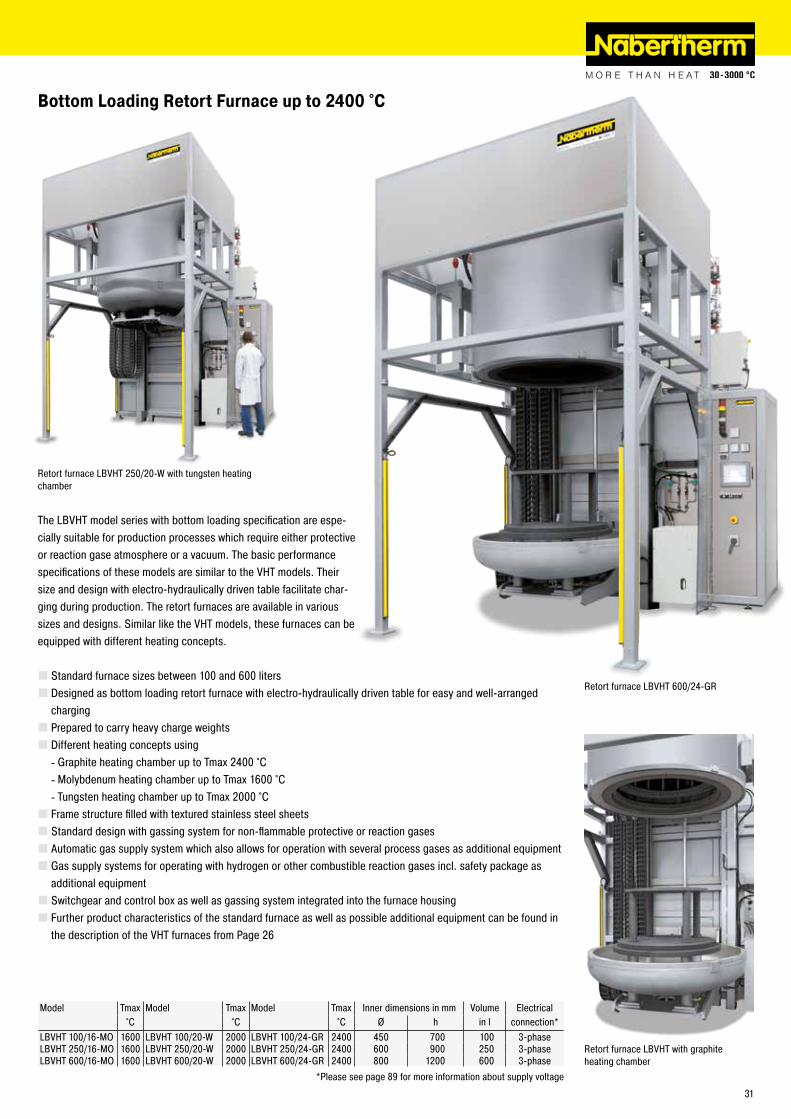
The LBVHT model series with bottom loading specification are espe-cially suitable for production processes which require either protective or reaction gase atmosphere or a vacuum. The basic performance specifications of these models are similar to the VHT models. Their size and design with electro-hydraulically driven table facilitate char-ging during production. The retort furnaces are available in various sizes and designs. Similar like the VHT models, these furnaces can be equipped with different heating concepts.
� Standard furnace sizes between 100 and 600 liters � Designed as bottom loading retort furnace with electro-hydraulically driven table for easy and well-arranged charging � Prepared to carry heavy charge weights � Different heating concepts using
- Graphite heating chamber up to Tmax 2400 °C - Molybdenum heating chamber up to Tmax 1600 °C - Tungsten heating chamber up to Tmax 2000 °C
� Frame structure filled with textured stainless steel sheets � Standard design with gassing system for non-flammable protective or reaction gases � Automatic gas supply system which also allows for operation with several process gases as additional equipment � Gas supply systems for operating with hydrogen or other combustible reaction gases incl. safety package as additional equipment � Switchgear and control box as well as gassing system integrated into the furnace housing � Further product characteristics of the standard furnace as well as possible additional equipment can be found in the description of the VHT furnaces from Page 26
Bottom Loading Retort Furnace up to 2400 °C
Retort furnace LBVHT 250/20-W with tungsten heating chamber
Retort furnace LBVHT with graphite heating chamber
Model Tmax Model Tmax Model Tmax Inner dimensions in mm Volume Electrical°C °C °C Ø h in l connection*
LBVHT 100/16-MO 1600 LBVHT 100/20-W 2000 LBVHT 100/24-GR 2400 450 700 100 3-phaseLBVHT 250/16-MO 1600 LBVHT 250/20-W 2000 LBVHT 250/24-GR 2400 600 900 250 3-phaseLBVHT 600/16-MO 1600 LBVHT 600/20-W 2000 LBVHT 600/24-GR 2400 800 1200 600 3-phase
*Please see page 89 for more information about supply voltage
Retort furnace LBVHT 600/24-GR
31
Model Tmax Work space dimensions Useful volume Outer dimensions in mm Heating power Electrical°C Ø x h in mm in l W D H in KW1 connection*
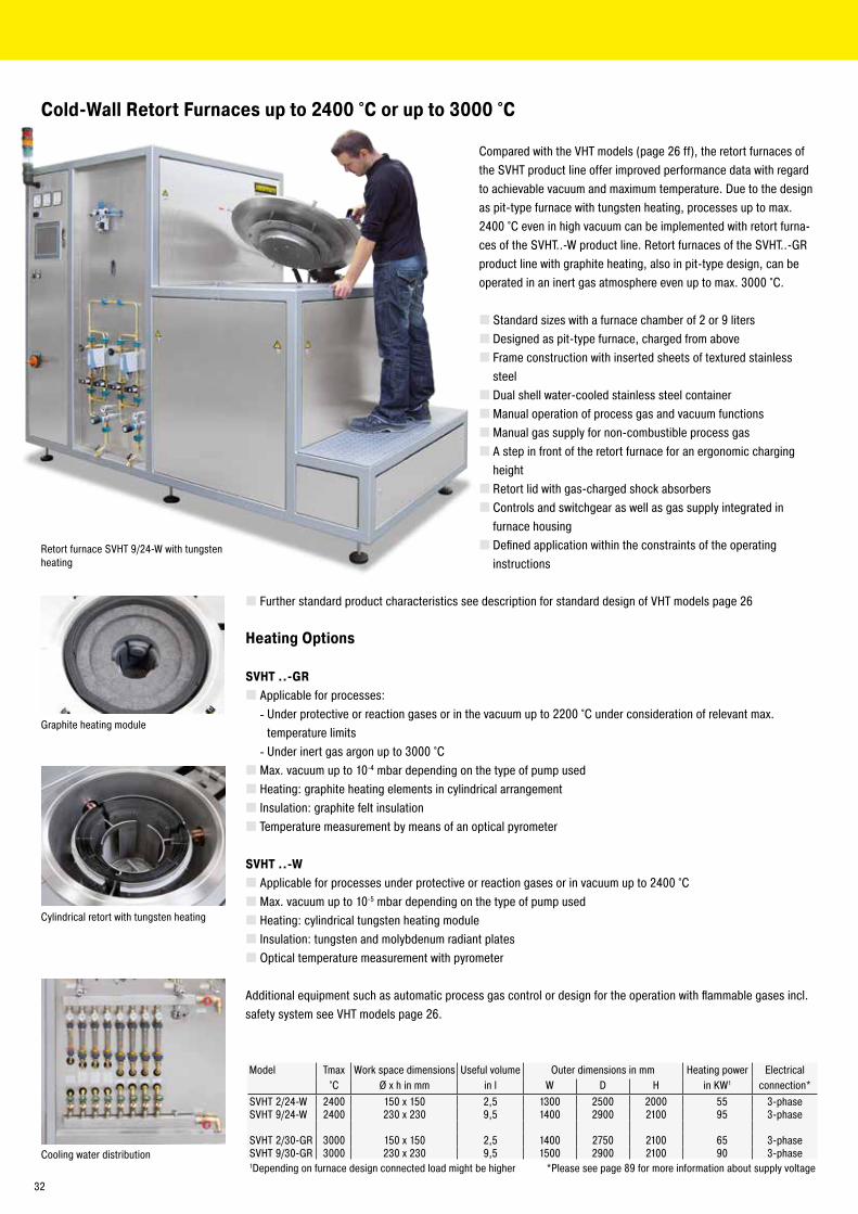
SVHT 2/24-W 2400 150 x 150 2,5 1300 2500 2000 55 3-phaseSVHT 9/24-W 2400 230 x 230 9,5 1400 2900 2100 95 3-phase
SVHT 2/30-GR 3000 150 x 150 2,5 1400 2750 2100 65 3-phaseSVHT 9/30-GR 3000 230 x 230 9,5 1500 2900 2100 90 3-phase1Depending on furnace design connected load might be higher *Please see page 89 for more information about supply voltage
Cold-Wall Retort Furnaces up to 2400 °C or up to 3000 °C
Compared with the VHT models (page 26 ff), the retort furnaces of the SVHT product line offer improved performance data with regard to achievable vacuum and maximum temperature. Due to the design as pit-type furnace with tungsten heating, processes up to max. 2400 °C even in high vacuum can be implemented with retort furna-ces of the SVHT..-W product line. Retort furnaces of the SVHT..-GR product line with graphite heating, also in pit-type design, can be operated in an inert gas atmosphere even up to max. 3000 °C.
� Standard sizes with a furnace chamber of 2 or 9 liters � Designed as pit-type furnace, charged from above � Frame construction with inserted sheets of textured stainless steel � Dual shell water-cooled stainless steel container �Manual operation of process gas and vacuum functions �Manual gas supply for non-combustible process gas � A step in front of the retort furnace for an ergonomic charging height � Retort lid with gas-charged shock absorbers � Controls and switchgear as well as gas supply integrated in furnace housing � Defined application within the constraints of the operating instructions
Retort furnace SVHT 9/24-W with tungsten heating
Cylindrical retort with tungsten heating
Graphite heating module
Cooling water distribution
� Further standard product characteristics see description for standard design of VHT models page 26
Heating Options
SVHT ..-GR � Applicable for processes:
- Under protective or reaction gases or in the vacuum up to 2200 °C under consideration of relevant max. temperature limits - Under inert gas argon up to 3000 °C
� Max. vacuum up to 10-4 mbar depending on the type of pump used � Heating: graphite heating elements in cylindrical arrangement � Insulation: graphite felt insulation � Temperature measurement by means of an optical pyrometer
SVHT ..-W � Applicable for processes under protective or reaction gases or in vacuum up to 2400 °C � Max. vacuum up to 10-5 mbar depending on the type of pump used � Heating: cylindrical tungsten heating module � Insulation: tungsten and molybdenum radiant plates � Optical temperature measurement with pyrometer
Additional equipment such as automatic process gas control or design for the operation with flammable gases incl. safety system see VHT models page 26.
32

Indirect cooling (hot-wall retort furnaces) � Ambient air is blown onto the outer retorte surface to cool it down. The waste heat is removed via the exhaust air outlet of the furnace. � The charge is cooled indirectly, which means that the atmosphere in the retort is not affected by the cooling � The charge cannot be quenched with the cooling system
Direct cooling (cold-wall and hot-wall retort furnaces) � Rapid gas cooling in the retort. For this purpose, the furnace atmosphere is circulated through a heat exchanger. � The system pressure is not increased by the cooling; there is no gas quenching at high pressure � Not available for processes with flammable furnace atmospheres
Retort Furnace Cooling Systems
Schematic presentation of rapid gas cooling1 Gas heat exchanger2 Radial fan3 Shut-off valves
Rapid gas cooling, cold-wall retort furnace VHT 8/16-MO
Fan cooling, hot-wall retort furnace NRA 400/03
Cooling Behavior of Hot-Wall Retort Furnace with Charge (Example)
Cooling Behavior of Cold-Wall Retort Furnace with Charge (Example)
SetpointWithout coolingIndirect coolingRapid gas coolingIndirect cooling and rapid gas cooling
With rapid gas coolingWithout rapid gas cooling
Time [min]
Tem
pera
ture
[°C]
Tem
pera
ture
[°C]
Time [min]
33

Vertical tube furnace RHTV 50/150/17 with stand and gas supply system 2 as additional equipment
Thermocouple for charge control in the furnace RHTH 120/600/18
Sintering under hydrogen in a tube furnace of RHTH product line Rotary Tube Furnace RSR 250/3500/15S
Tube Furnaces for Processes under Flammable or Non-Flammable Protective or Reaction Gases or under Vacuum
With the wide range of available accessories, our professional tube furnaces can be designed optimally to suit various processes. By upgrading with different gas supply systems, processes can be carried out in a protective gas atmosphere, in vacuum, or under flammable protective or reaction gases. In addition to the convenient standard controllers, modern PLC controls can be used also.
� Tube furnaces (static) with Tmax 1100 °C to 1800 °C (max. 1400 °C in vacuum) for horizontal or vertical operation � Rotary tube furnaces for batch or continuous processes with Tmax 1100 °C or 1300 °C � Different working tube materials designed for various process requirements � Defined application within the constraints of the operating instructions � NTLog Basic for Nabertherm controller: recording process data with a USB flash drive
Additional equipment � Different gas supply system packages for flammable or non-flammable protective or reaction gases � Vacuum operation � Multiple zone design to optimize temperature uniformity � Charge control with temperature measurement in the working tube and in the furnace chamber outside the tube � Display of temperature in the working tube with additional thermocouple � Cooling systems for accelerated cooling of the working tube and the charge � Individual solutions for process optimization available
Compact laboratory tube furnace with manual gas supply system
High-temperature tube furnace for four different protective gases
34
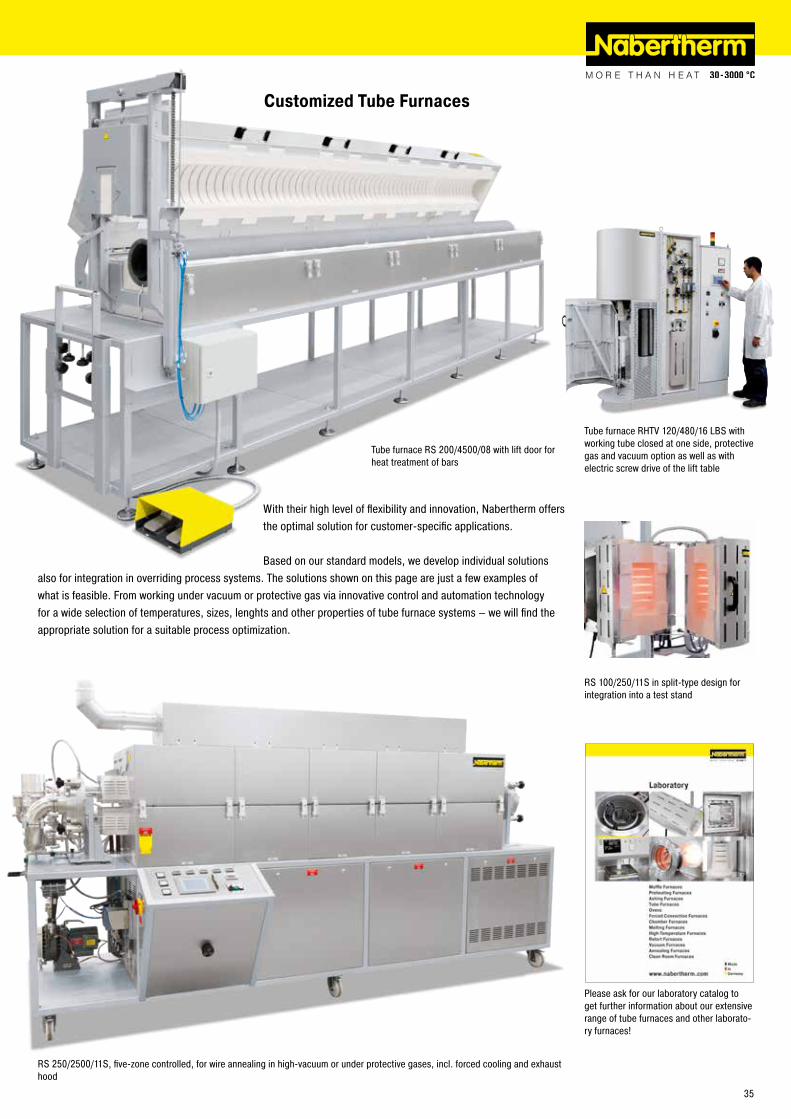
Customized Tube Furnaces
With their high level of flexibility and innovation, Nabertherm offers the optimal solution for customer-specific applications.
Based on our standard models, we develop individual solutions also for integration in overriding process systems. The solutions shown on this page are just a few examples of what is feasible. From working under vacuum or protective gas via innovative control and automation technology for a wide selection of temperatures, sizes, lenghts and other properties of tube furnace systems – we will find the appropriate solution for a suitable process optimization.
RS 100/250/11S in split-type design for integration into a test stand
RS 250/2500/11S, five-zone controlled, for wire annealing in high-vacuum or under protective gases, incl. forced cooling and exhaust hood
Tube furnace RS 200/4500/08 with lift door for heat treatment of bars
Tube furnace RHTV 120/480/16 LBS with working tube closed at one side, protective gas and vacuum option as well as with electric screw drive of the lift table
Please ask for our laboratory catalog to get further information about our extensive range of tube furnaces and other laborato-ry furnaces!
35

These models are particularly suitable for continuous heat treatment at operation temperatures up to 1200 °C. The modular design allows adjustment to different length and width requirements. The heating elements are mounted on only one side of the furnace and can be changed individually during operation. Optimum temperature uniformity is achieved by means of a multiple zone control system tailored to the furnace dimensions.
� Tmax 1200 °C � Modular design, variable length � Small outer dimensions due to efficient microporous silica insulation � Special heating elements that can be changed during operation � Heating from the ceiling � Optimum temperature uniformity by means of multiple zone control � Defined application within the constraints of the operating instructions � Controls description see page 88
Additional equipment � Gas supply systems for the working tubes for non-flammable or flammable protective or reaction gases including hydrogen, with burn off torch and safety technology � Process and charge documentation � Double chamber furnace system with parallel chambers for simultaneous operation at different temperatures � Process control and documentation via VCD software package or Nabertherm Control Center (NCC) for monitoring, documentation and control see page 88
Wire and Strand Annealing Furnaces
Strand annealing furnace D 390/S
Model Tmax Inner dimensions in mm Volume Outer dimensions in mm Heating Electrical°C w d h in l W D H power in kW1 connection*
D 20/S 1200 400 1000 50 20 900 1200 1350 9 3-phaseD 30/S 1200 600 1000 50 30 1100 1200 1350 12 3-phaseD 50/S 1200 200 3600 50 50 700 4000 1150 15 3-phaseD 60/S 1200 200 5600 50 60 700 6000 1350 36 3-phaseD 70/S 1200 350 3600 50 70 850 4000 1100 36 3-phaseD 110/S 1200 480 4600 50 110 980 5000 1450 36 3-phaseD 130/S 1200 650 3600 50 130 1150 4000 1150 60 3-phaseD 180/S 1200 480 7600 50 180 980 8000 1350 80 3-phaseD 250/S 1200 950 5600 50 250 1400 6000 1350 80 3-phaseD 320/S 1200 850 7600 100 320 1400 8000 1350 160 3-phase
1Depending on furnace design connected load might be higher *Please see page 89 for more information about supply voltage
D 250/S in production
Strand annealing furnaces based on a tube furnace with a length of 6 meters
Wire annealing furnace based on a tube furnace with safety package for hydrogen as process gas
36
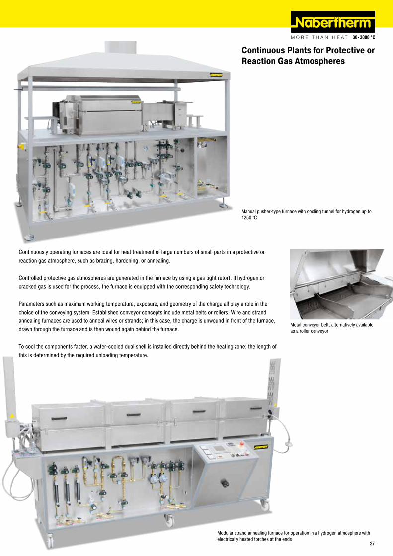
Continuous Plants for Protective or Reaction Gas Atmospheres
Continuously operating furnaces are ideal for heat treatment of large numbers of small parts in a protective or reaction gas atmosphere, such as brazing, hardening, or annealing.
Controlled protective gas atmospheres are generated in the furnace by using a gas tight retort. If hydrogen or cracked gas is used for the process, the furnace is equipped with the corresponding safety technology.
Parameters such as maximum working temperature, exposure, and geometry of the charge all play a role in the choice of the conveying system. Established conveyor concepts include metal belts or rollers. Wire and strand annealing furnaces are used to anneal wires or strands; in this case, the charge is unwound in front of the furnace, drawn through the furnace and is then wound again behind the furnace.
To cool the components faster, a water-cooled dual shell is installed directly behind the heating zone; the length of this is determined by the required unloading temperature.
Manual pusher-type furnace with cooling tunnel for hydrogen up to 1250 °C
Modular strand annealing furnace for operation in a hydrogen atmosphere with electrically heated torches at the ends
Metal conveyor belt, alternatively available as a roller conveyor
37

Salt-bath furnaces have an excellent temperature uniformity and ensure very good heat transfer to the work piece. Generally, heat treatment can be carried out with shorter dwell times than in chamber furnaces. Since the charge is heat treated with the exclusion of oxygen, scale and discoloration on the surface of the parts are kept to a minimum.
The salt-bath furnaces TS 20/15 - TSB 90/80 can be used for heat treatment of metals in neutral and active salt baths. They are used for processes such as nitriding according to Tenifer up to 600 °C, carburization to 950 °C or bright annealing to 1000 °C.
The crucible is inserted so that it is suspended in the salt-bath furnace and can be replaced easily if necessary. Two crucible types are available:
� Type P: low carbon steel and CrNi plated for carburizing, neutral salt and annealing baths up to 850 °C � Type C: high alloy CrNi steel for neutral salt and annealing baths up to 1000 °C and for dip brazing of aluminum
Crucibles are wearing parts because they are exposed to thermal stress during the heating and cooling process and corrosive salt. The following parameters influence wear of the crucible:
�Working temperature � Number of heating and cooling cycles � Salt � Charge material � Charge quantity � Contamination of the charge
The crucible must be checked regularly for wear and damage. We recommend to order a replacement crucible together with the furnace.
Salt-Bath Furnaces for Heat Treatment of Steel or Light Metals Electrically Heated or Gas-Fired
Salt-bath furnace TS 30/30, electrically heatedSalt-bath furnace TSB 30/30, gas-fired
38
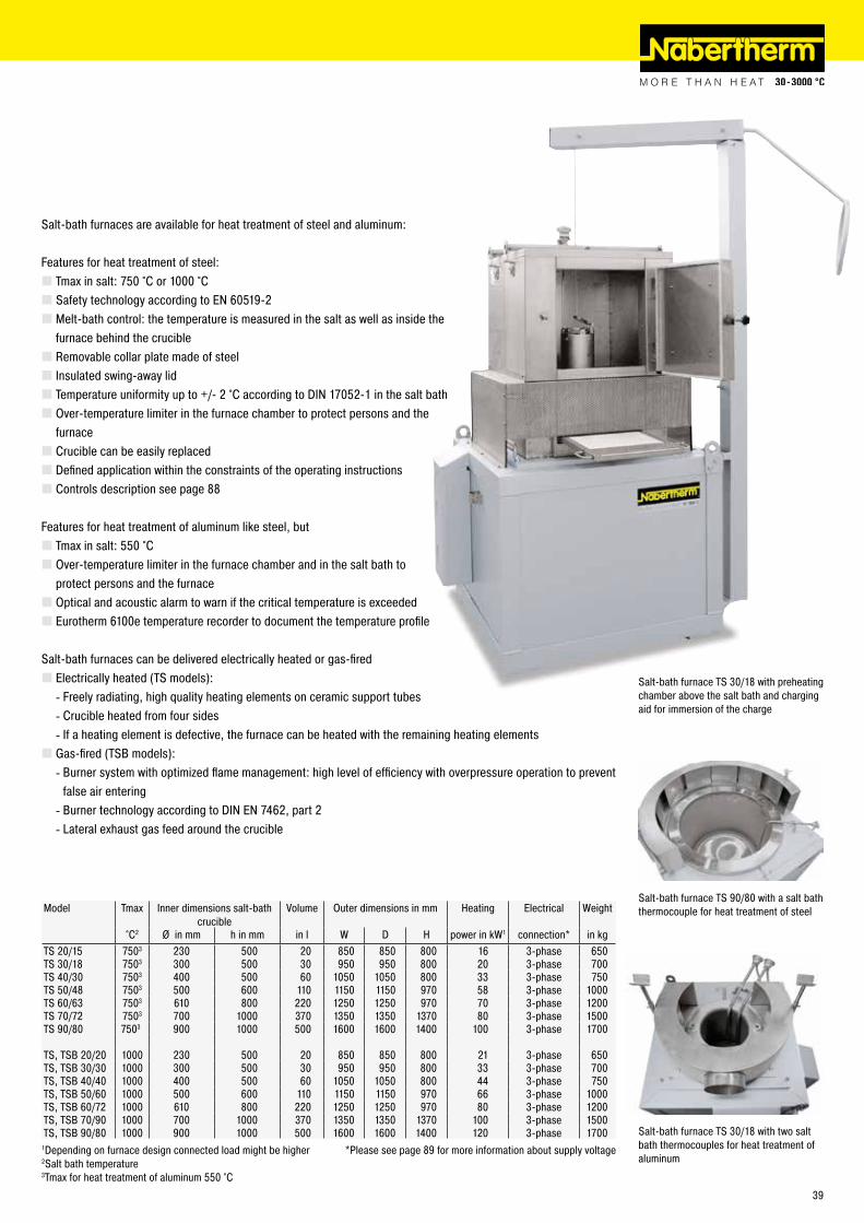
Salt-bath furnace TS 30/18 with preheating chamber above the salt bath and charging aid for immersion of the charge
Salt-bath furnaces are available for heat treatment of steel and aluminum:
Features for heat treatment of steel: � Tmax in salt: 750 °C or 1000 °C � Safety technology according to EN 60519-2 � Melt-bath control: the temperature is measured in the salt as well as inside the furnace behind the crucible � Removable collar plate made of steel � Insulated swing-away lid � Temperature uniformity up to +/- 2 °C according to DIN 17052-1 in the salt bath � Over-temperature limiter in the furnace chamber to protect persons and the furnace � Crucible can be easily replaced � Defined application within the constraints of the operating instructions � Controls description see page 88
Features for heat treatment of aluminum like steel, but � Tmax in salt: 550 °C � Over-temperature limiter in the furnace chamber and in the salt bath to protect persons and the furnace � Optical and acoustic alarm to warn if the critical temperature is exceeded � Eurotherm 6100e temperature recorder to document the temperature profile
Salt-bath furnaces can be delivered electrically heated or gas-fired � Electrically heated (TS models):
- Freely radiating, high quality heating elements on ceramic support tubes - Crucible heated from four sides - If a heating element is defective, the furnace can be heated with the remaining heating elements
� Gas-fired (TSB models): - Burner system with optimized flame management: high level of efficiency with overpressure operation to prevent false air entering - Burner technology according to DIN EN 7462, part 2 - Lateral exhaust gas feed around the crucible
Salt-bath furnace TS 90/80 with a salt bath thermocouple for heat treatment of steel
Salt-bath furnace TS 30/18 with two salt bath thermocouples for heat treatment of aluminum
Model Tmax Inner dimensions salt-bath crucible
Volume Outer dimensions in mm Heating Electrical Weight
°C2 Ø in mm h in mm in l W D H power in kW1 connection* in kgTS 20/15 7503 230 500 20 850 850 800 16 3-phase 650TS 30/18 7503 300 500 30 950 950 800 20 3-phase 700TS 40/30 7503 400 500 60 1050 1050 800 33 3-phase 750TS 50/48 7503 500 600 110 1150 1150 970 58 3-phase 1000TS 60/63 7503 610 800 220 1250 1250 970 70 3-phase 1200TS 70/72 7503 700 1000 370 1350 1350 1370 80 3-phase 1500TS 90/80 7503 900 1000 500 1600 1600 1400 100 3-phase 1700
TS, TSB 20/20 1000 230 500 20 850 850 800 21 3-phase 650TS, TSB 30/30 1000 300 500 30 950 950 800 33 3-phase 700TS, TSB 40/40 1000 400 500 60 1050 1050 800 44 3-phase 750TS, TSB 50/60 1000 500 600 110 1150 1150 970 66 3-phase 1000TS, TSB 60/72 1000 610 800 220 1250 1250 970 80 3-phase 1200TS, TSB 70/90 1000 700 1000 370 1350 1350 1370 100 3-phase 1500TS, TSB 90/80 1000 900 1000 500 1600 1600 1400 120 3-phase 1700
1Depending on furnace design connected load might be higher *Please see page 89 for more information about supply voltage2Salt bath temperature3Tmax for heat treatment of aluminum 550 °C
39

Salt-Bath Furnaces for Heat Treatment of Steel or Light Metals Electrically Heated or Gas-Fired
Accessories � Exhaust gas collection at crucible rim
- For the direct extraction of vapors and exhaust gases - Flange on the back to connect the customer’s exhaust gas system - Only in combination with a lid that is manually placed on top
� Pneumatic lid opening - Pneumatic lateral movement of the swivel lid - Manual lowering and raising of the lid with a lever - Foot pedal control - Not available in combination with exhaust gas collection at crucible rim
� Charging basket for bulk materials - Possible lid closing over the salt bath with inserted charging basket - For manual charging of small martempering and salt baths - Charging with a crane or charging aid for large martempering and salt baths
Salt-bath furnace TS 40/30 with exhaust gas collection at crucible rim and manual lid
Charging basket for salt-bath furnaces
Salt-bath furnace TS 40/30 with pneumatic lid opening
� Process control and documentation via Nabertherm Control Center NCC for monitoring, documentation, and control
Process Examples with Petrofer and Durferrit Salts
TS models up to 750 °CNitriding Nitrogen 420, Nitrogen 460, Nitrogen 500Annealing and blackening SFS 240Hardening, Tempering, Annealing, Quen-ching
GS 185, GS 230, GS 250, GS 345, GS 405, GS 406, GS 430, GS 520
Preheating, annealing of gold, silver or brass GS 560, HS 545
TS models up to 1000 °CCarbonitriding, carburizing Carbogen VC, Carbogen OKAnnealing, hardening, preheating HS 535, HS 545, HS 535, GS 560, GS 660Carburizing Carbogen Universal, Carborapid + GS-ZS, Carbomax +GS-ZS, Carbogen
800/800 ST, Carbogen 1000/ 1000 ST, CECONTROL 50H, CECONTROL 80B, CECONTROL 110B, CECONSTANT 80, CECONSTANT 100
Preheating of high-speed steel, annealing GS 540, GS 660, GS 670, GS 750, HS 550, HS 635, HS 760Preheating, annealing of gold, silver or brass GS 560, HS 545
TS models for aluminumArtificial ageing, solution annealing AS 135, AS 200, AS 225, AVS 220, AVS 250
40

Martempering hardening in practice
Martempering Furnaces using Neutral Salts Electrically Heated
QS 20 - QS 400 martempering furnaces are filled with neutral salt and offer remarkably rapid and intensive heat transmission to the workpiece while ensuring optimum temperature uniformity. Since the batch is heat treated with the exclusion of oxygen, scale and discoloration on the surface of the parts are reduced to a minimum. For working temperatures at between 180 °C and 500 °C these martempering furnaces are useful for quenching or cooling with minimal workpiece distortion, retempering, austempering for optimal toughness, recrystallization annealing after electrical discharge machining (EDM) and for blueing.
The quenching or cooling process is applied in order to achieve an even temperature uniformity throughout the workpiece‘s entire cross-section before the formation of martensite and to avoid distortion and formation of cracks in complex mechanical components during the subsequent hardening process.
Tempering in a martempering bath is the same as the tempering process in forced convection furnace and is used to reduce a previously hardened workpiece to a desired hardness, to increase toughness and reduce stress within the workpiece.
Austempering is a good choice to achieve a high level of toughness and dimensional accuracy in oil hardened low-alloy steels. Workpieces subject to austempering have high tensile strength and good elasticity.
� Tmax 550 °C � Very good temperature uniformity � Martemper bath temperature control � Over-temperature limiter with adjustable cutout temperature for thermal protection class 2 in accordance with EN 60519-2 as temperature limiter to protect the furnace and load � Heating with immersion heating elements � Rectangular crucible, integrated in the housing � Charging basket � Crucible made of 1.4828 � Defined application within the constraints of the operating instructions � NTLog Basic for Nabertherm controller: recording of process data with USB-flash drive � Controls description see page 88
Additional equipment � Charging aid with hand crank and cable winch, mounted on side of furnace � Process control and documentation via VCD software package for monitoring, documentation and control
Model Tmax Inner dimensions in mm Volume Outer dimensions in mm Heating Electrical Weight°C w d h in l W D H power in kW1 connection* in kg
QS 20 550 300 210 460 20 610 580 920 2.6 1-phase 110QS 30 550 300 210 580 30 610 580 920 3.2 1-phase 140QS 70 550 400 300 680 70 750 680 980 7.5 3-phase 240QS 200 550 540 520 880 200 900 900 1200 18.0 3-phase 660QS 400 550 730 720 980 400 1100 1100 1300 24.0 3-phase 1150
1Depending on furnace design connected load might be higher *Please see page 89 for more information about supply voltageMartempering furnace QS 30 with charging aid
Marttempering furnace QS 20 with char-ging basket
Heating element in the crucible
Process Examples with Petrofer and Durferrit Salts
QS-baths (steel/Nitinol)Hardening, isothermic treatment of steels up to 950 °C, stress relieving, annealing, bluing, bainitization
AS 135, AS 140, AS 220, AS 225, AS 200, AS 235, GS 230
Homogenization annealing, recrystallization annealing; warm-bath curing, tempe-ring, banitizing, bluing
AS 300
41

42
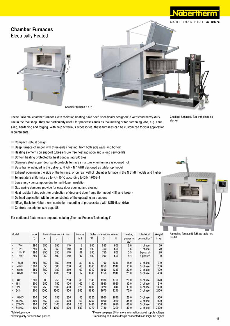
These universal chamber furnaces with radiation heating have been specifically designed to withstand heavy-duty use in the tool shop. They are particularly useful for processes such as tool making or for hardening jobs, e.g. anne-aling, hardening and forging. With help of various accessories, these furnaces can be customized to your application requirements.
� Compact, robust design � Deep furnace chamber with three-sides heating: from both side walls and bottom � Heating elements on support tubes ensure free heat radiation and a long service life � Bottom heating protected by heat conducting SiC tiles � Stainless steel upper door jamb protects furnace structure when furnace is opened hot � Base frame included in the delivery, N 7/H - N 17/HR designed as table-top model � Exhaust opening in the side of the furnace, or on rear wall of chamber furnace in the N 31/H models and higher � Temperature uniformity up to +/- 10 °C according to DIN 17052-1 � Low energy consumption due to multi-layer insulation � Gas spring dampers provide for easy door opening and closing � Heat resistant zinc paint for protection of door and door frame (for model N 81 and larger) � Defined application within the constraints of the operating instructions � NTLog Basic for Nabertherm controller: recording of process data with USB-flash drive � Controls description see page 88
For additional features see separate catalog „Thermal Process Technology I“
Chamber Furnaces Electrically Heated
Model Tmax Inner dimensions in mm Volume Outer dimensions in mm Heating Electrical Weight°C w d h in l W D H power in
kW3connection* in kg
N 7/H1 1280 250 250 140 9 800 650 600 3.0 1-phase 60N 11/H1 1280 250 350 140 11 800 750 600 3.5 1-phase 70N 11/HR1 1280 250 350 140 11 800 750 600 5.5 3-phase2 70N 17/HR1 1280 250 500 140 17 800 900 600 6.4 3-phase2 90
N 31/H 1280 350 350 250 30 1040 1100 1340 15.0 3-phase 210N 41/H 1280 350 500 250 40 1040 1250 1340 15.0 3-phase 260N 61/H 1280 350 750 250 60 1040 1500 1340 20.0 3-phase 400N 87/H 1280 350 1000 250 87 1040 1750 1340 25.0 3-phase 480
N 81 1200 500 750 250 80 1140 1900 1790 20.0 3-phase 820N 161 1200 550 750 400 160 1180 1930 1980 30.0 3-phase 910N 321 1200 750 1100 400 320 1400 2270 2040 47.0 3-phase 1300N 641 1200 1000 1300 500 640 1690 2670 2240 70.0 3-phase 2100
N 81/13 1300 500 750 250 80 1220 1960 1840 22.0 3-phase 900N 161/13 1300 550 750 400 160 1260 1990 2030 35.0 3-phase 1000N 321/13 1300 750 1100 400 320 1480 2330 2090 60.0 3-phase 1500N 641/13 1300 1000 1300 500 640 1770 2730 2290 80.0 3-phase 2500
1Table-top model *Please see page 89 for more information about supply voltage2Heating only between two phases 3Depending on furnace design connected load might be higher
Chamber furnace N 321 with charging stacker
Chamber furnace N 41/H
Annealing furnace N 7/H, as table-top model
43
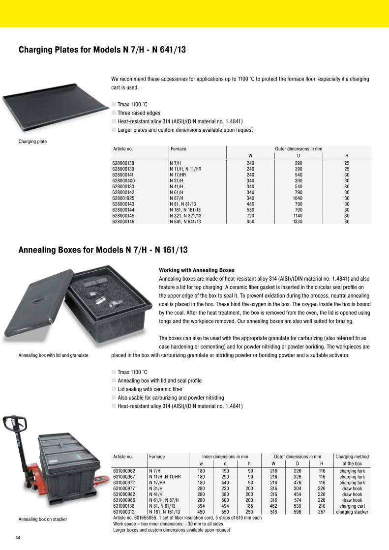
Charging Plates for Models N 7/H - N 641/13
Annealing Boxes for Models N 7/H - N 161/13
We recommend these accessories for applications up to 1100 °C to protect the furnace floor, especially if a charging cart is used.
� Tmax 1100 °C � Three raised edges � Heat-resistant alloy 314 (AISI)/(DIN material no. 1.4841) � Larger plates and custom dimensions available upon request
Article no. Furnace Outer dimensions in mmW D H
628000138 N 7/H 240 290 25628000139 N 11/H, N 11/HR 240 390 25628000141 N 17/HR 240 540 30628000400 N 31/H 340 390 30628000133 N 41/H 340 540 30628000142 N 61/H 340 790 30628001925 N 87/H 340 1040 30628000143 N 81, N 81/13 480 790 30628000144 N 161, N 161/13 530 790 30628000145 N 321, N 321/13 720 1140 30628000146 N 641, N 641/13 950 1330 30
Article no. Furnace Inner dimensions in mm Outer dimensions in mm Charging methodw d h W D H of the box
631000962 N 7/H 180 190 90 216 226 116 charging fork631000967 N 11/H, N 11/HR 180 290 90 216 326 116 charging fork631000972 N 17/HR 180 440 90 216 476 116 charging fork631000977 N 31/H 280 230 200 316 304 226 draw hook631000982 N 41/H 280 380 200 316 454 226 draw hook631000986 N 61/H, N 87/H 280 500 200 316 574 226 draw hook631000138 N 81, N 81/13 394 494 185 462 530 210 charging cart631000312 N 161, N 161/13 450 550 250 515 596 357 charging stackerArticle no. 601655055, 1 set of fiber insulation cord, 5 strips of 610 mm eachWork space = box inner dimensions: - 30 mm to all sidesLarger boxes and custom dimensions available upon request
Working with Annealing BoxesAnnealing boxes are made of heat-resistant alloy 314 (AISI)/(DIN material no. 1.4841) and also feature a lid for top charging. A ceramic fiber gasket is inserted in the circular seal profile on the upper edge of the box to seal it. To prevent oxidation during the process, neutral annealing coal is placed in the box. These bind the oxygen in the box. The oxygen inside the box is bound by the coal. After the heat treatment, the box is removed from the oven, the lid is opened using tongs and the workpiece removed. Our annealing boxes are also well suited for brazing.
The boxes can also be used with the appropriate granulate for carburizing (also referred to as case hardening or cementing) and for powder nitriding or powder boriding. The workpieces are
placed in the box with carburizing granulate or nitriding powder or boriding powder and a suitable activator.
� Tmax 1100 °C � Annealing box with lid and seal profile � Lid sealing with ceramic fiber � Also usable for carburizing and powder nitriding � Heat-resistant alloy 314 (AISI)/(DIN material no. 1.4841)
Charging plate
Annealing box with lid and granulate
Annealing box on stacker
44
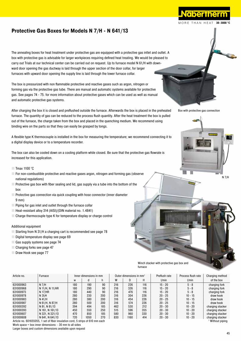
N 7/H
Protective Gas Boxes for Models N 7/H - N 641/13
The annealing boxes for heat treatment under protective gas are equipped with a protective gas intlet and outlet. A box with protective gas is advisable for larger workpieces requiring defined heat treating. We would be pleased to carry out Trials at our technical center can be carried out on request. Up to furnace model N 61/H with down-ward door opening the gas ductway is laid through the upper section of the door collar, for larger furnaces with upward door opening the supply line is laid through the lower furnace collar.
The box is pressurized with non flammable protective and reactive gases such as argon, nitrogen or forming gas via the protective gas tube. There are manual and automatic systems available for protective gas. See pages 74 - 75. for more information about protective gases which can be used as well as manual and automatic protective gas systems.
After charging the box it is closed and preflushed outside the furnace. Afterwards the box is placed in the preheated furnace. The quantity of gas can be reduced to the process flush quantity. After the heat treatment the box is pulled out of the furnace, the charge taken from the box and placed in the quenching medium. We recommend using binding wire on the parts so that they can easily be grasped by tongs.
A flexible type K thermocouple is installed in the box for measuring the temperature; we recommend connecting it to a digital display device or to a temperature recorder.
The box can also be cooled down on a cooling platform while closed. Be sure that the protective gas flowrate is increased for this application.
� Tmax 1100 °C � For non-combustible protective and reactive gases argon, nitrogen and forming gas (observe national regulations) � Protective gas box with fiber sealing and lid, gas supply via a tube into the bottom of the box � Protective gas connection via quick coupling with hose connector (inner diameter 9 mm) � Piping for gas inlet and outlet through the furnace collar � Heat-resistant alloy 314 (AISI)/(DIN material no. 1.4841) � Charge thermocouple type K for temperature display or charge control
Additional equipment � Starting from N 31/H a charging cart is recommended see page 78 � Digital temperature display see page 69 � Gas supply systems see page 74 � Charging forks see page 47 � Draw Hook see page 77
Article no. Furnace Inner dimensions in mm Outer dimensions in mm1 Preflush rate Process flush rate Charging methodw d h W D H l/min l/min of the box
631000963 N 7/H 180 190 90 216 226 116 15 - 20 5 - 8 charging fork631000968 N 11/H, N 11/HR 180 290 90 216 326 116 15 - 20 5 - 8 charging fork631000973 N 17/HR 180 440 90 216 476 116 15 - 20 5 - 8 charging fork631000978 N 31/H 280 230 200 316 304 226 20 - 25 10 - 15 draw hook631000983 N 41/H 280 380 200 316 454 226 20 - 25 10 - 15 draw hook631000987 N 61/H, N 87/H 280 500 200 316 574 226 20 - 25 10 - 15 draw hook631000392 N 81, N 81/13 394 494 185 462 530 212 20 - 30 10 - 20 charging stacker631000393 N 161, N 161/13 450 550 250 515 596 355 20 - 30 10 - 20 charging stacker631000607 N 321, N 321/13 470 850 185 580 960 330 20 - 30 10 - 20 charging stacker631000608 N 641, N 641/13 720 1050 270 830 1160 414 20 - 30 10 - 20 charging stackerArticle no. 601655055, 1 set of fiber insulation cord, 5 strips of 610 mm each 1 Without pipingWork space = box inner dimensions: - 30 mm to all sidesLarger boxes and custom dimensions available upon request
Box with protective gas connection
Winch stacker with protective gas box and furnace
45

Protective Gas Boxes with Evacuation Lid for Models N 7/H - N 614/13
For heat treatment of bulk goods and hollow parts under protective gas atmosphere we recommend the usage of protective gas boxes with an additional evacuation lid.
These boxes are equipped with a lid for top charging, protective gas inlet and outlet as well as a evacuation lid with rubber sealing gasket. Gas ductwork and handling while hot is the same as the protective gas boxes described on page 45. In addition, these
boxes also feature a connection for a vacuum pump with a shut-off valve.
After charging the box in a cold state it is evacuated and afterwards flushed with protective gas. By repeating this process once or several times the results are considerably improved. After the box was flushed with protective gas the last time, the evacuation lid is removed and the box is placed into the preheated furnace. Protective gas is used for heat treatment. Thus traces of oxygen in the box can be reduced by a considerable amount which improves the quality of the components accordingly.
After the heat treatment the box is taken out of the furnace and can be cooled in air or be opened to remove the charge.
The box can also be force-cooled on a cooling platform while closed. Be sure that the protective gas flowrate is increased for this application.
� Tmax 1100 °C � For non-combustible protective and reactive gases argon, nitrogen and forming gas (observe national regulations) � Protective gas box with fiber sealing and lid with locks, recess for evacuation lid, gas inlet via a pipe into the bottom of the box � Evacuation lid with rubber sealing (Elastomer) and manometer � Protective gas connection via threeway ball valve and quick coupling with hose connector (inner diameter 9 mm) � Piping for gas inlet and outlet through the furnace collar � Heat-resistant alloy 314 (AISI)/(DIN material no. 1.4841) � Charge thermocouple type K for temperature display or charge control
Additional equipment � Starting from N 31/H a charging cart is recommended see page 78 � Digital temperature display see page 69 � Vacuum pump see page 75 � Gas supply systems see page 74 � Charging forks see page 47 � Draw Hook siehe Seite 77
Article no. Furnace Inner dimensions in mm Outer dimensions in mm1 Preflush rate Process flush rate Charging methodw d h W D H l/min l/min of the box
631000966 N 7/H 170 170 70 212 212 106 15 - 20 5 - 8 charging fork631000971 N 11/H, N 11/HR 170 270 70 212 312 106 15 - 20 5 - 8 charging fork631000976 N 17/HR 170 420 70 212 462 106 15 - 20 5 - 8 charging fork631000981 N 31/H 250 200 150 292 242 178 20 - 25 10 - 15 draw hook631000985 N 41/H 250 350 150 292 392 178 20 - 25 10 - 15 draw hook631000989 N 61/H, N 87/H 250 500 150 292 542 178 20 - 25 10 - 15 draw hook631000526 N 81, N 81/13 354 494 185 422 905 215 20 - 30 10 - 20 charging stacker631000527 N 161, N 161/13 400 550 250 468 965 350 20 - 30 10 - 20 charging stacker631006325 N 321, N 321/13 500 700 200 650 1150 340 20 - 30 10 - 20 charging stacker631006326 N 641, N 641/13 700 900 250 850 1400 430 20 - 30 10 - 20 charging stackerArticle no. 601655055, 1 set of fiber insulation cord, 5 strips of 610 mm each 1 Without piping and evacuation lidWork space = box inner dimensions: - 30 mm to all sides Larger boxes and custom dimensions available upon request
Protective gas box for N 41/H furnace with additional evacuation lid
46

Protective Gas Boxes with Hinged Lids for Fast Quenching for Models N 7/H - N 31/H
Article no. Furnace Inner dimensions in mm Outer dimensions in mm1 Preflush rate Process flush rate
w d h W D H l/min l/min631000964 N 7/H 180 160 90 216 210 110 15 - 20 5 - 8631000969 N 11/H, N 11/HR 180 260 90 216 310 110 15 - 20 5 - 8631000974 N 17/HR 180 410 90 216 460 110 15 - 20 5 - 8631000979 N 31/H 260 220 120 290 272 140 20 - 25 10 - 15Work space = box inner dimensions: - 30 mm to all sides 1 Without pipingLarger boxes and custom dimensions available upon request
For heat treatment of small amounts of bulk material or small parts under protective gases with subsequent fast quenching in oil or water, we recommend to use protective gas boxes with a hinged lid. Boxes with an angled hinged lid on the front are equipped with a protective gas line on the rear wall. The supply line is run through the upper furnace collar.
After preflushing the box with non-flammable protective and reactive gases such as argon, nitrogen or forming gas 95/5, the box is placed with hinged lid first into the furnace. Due to a slight overpressure within the box the protective gas is vented off through the hinged lid.
After the heat treatment the box is taken out of the furnace and the charge is poured into quenching bath directly out of the box. By placing the box at an angle the hinged lid opens by itself. The contact with ambient air is reduced to a minimum.
� Tmax 1100 °C � For non-combustible protective and reactive gases argon, nitrogen and forming gas (observe national regulations) � Protective gas box with flap lid and gas supply from the rear wall � Protective gas connection via quick coupling with hose connector (inner diameter 9 mm) � Piping for gas inlet and outlet through the furnace collar � Lid remains closed through its own weight � Holder with hand handle � Heat-resistant alloy 314 (AISI)/(DIN material no. 1.4841) � Charge thermocouple type K for temperature display or charge control
Additional equipment � Starting from N 31/H a charging cart is recommended see page 78 � Digital temperature display see page 69 � Gas supply systems see page 74
Protective gas box with hinged lid
Charging Forks
� Charging forks to charge and remove protective gas boxes up to model N 17/H
Article no. Furnace631001016 N 7/H, N 11/H(R)631001017 N 17/HR
47

Working with Protective Gas Boxes with Hinged Lid in continuous OperationIn the case of successive protective gas heat treatment of individual parts, a gassing box is recommended, which remains in the furnace. For charging, the box is equipped with a flap lid to the front. The lid closes without a sealing profile against the oblique position of the box opening. Larger gas losses in comparison with removable boxes can be expected. For the protective gas supply the pipe goes through a bore on the rear wall of the furnace.
For charging, the box is opened in the furnace using a draw hook and the workpieces are placed into the box. The box is continuously flushed with non-flammable protective and reactive gases such as argon, nitrogen or forming gas 95/5. Due to a slight overpressure within the box the protective gas is vented off through the hinged lid.
After the heat treatment the box is opened using a draw hook and the workpieces are removed.
� Tmax 1100 °C � For non-combustible protective and reactive gases argon, nitrogen and forming gas (observe national regulations) � Protective gas box with flap lid and gas supply from the rear wall � Protective gas connection via quick coupling with hose connector (inner diameter 9 mm) � Piping for gas inlet and outlet through the rear wall � Front flap lid which opens downwards � Heat-resistant alloy 314 (AISI)/(DIN material no. 1.4841) � Charge thermocouple type K for temperature display or charge control � The furnace will not be equipped with a charging plate (protective gas box is permanently installed)
Additional equipment � Digital temperature display see page 69 � Gas supply systems see page 74
Gas Feed Boxes with Hinged Lid for Models N 7/H - N 87/H which Remain in the Furnace
Article no. Furnace Inner dimensions in mm Outer dimensions in mm1 Preflush rate Process flush rate
w d h W D H l/min l/min631000965 N 7/H 170 170 80 213 221 114 15 - 20 5 - 8631000970 N 11/H, N 11/HR 170 270 80 213 321 114 15 - 20 5 - 8631000975 N 17/HR 170 420 80 213 471 114 15 - 20 5 - 8631000980 N 31/H 270 260 190 303 321 224 20 - 25 10 - 15631000984 N 41/H 270 410 190 303 471 224 20 - 25 10 - 15631000988 N 61/H 270 660 190 303 721 224 20 - 25 10 - 15631000990 N 87/H 270 910 190 303 971 224 20 - 25 10 - 15Work space = box inner dimensions: - 30 mm to all sides 1 Without pipingLarger boxes and custom dimensions available upon request
Gas connection
Door
Protective gas box with hinged lid for permanent operation
Probes heat treated in different processes
48

Protective Gas Annealing Bag and Holder for Models N 7/H - N 87/H
When workpieces made of air-hardened steel must be heat treated under protective gas and quenched afterwards, the protective gas annealing bag with holder is an optimal solution. This system consists of a holder with charge carrier and protective gas tube as well as a bag made of stainless steel heat treating foil.
The charge is placed on the charge carrier and covered with the protective gas annealing bag. The bag is preflushed with non-flammable protective and reactive gases such as argon, nitrogen or forming gas 95/5 and placed together with the holder in the furnace. After the charge has been heated, the protective gas annealing bag and holder are removed from the furnace and cooled with the help of the forced cooling system or in still air. At the same time the workpiece remains in the bag in the protective gas atmosphere. This prevents oxidation from occuring. Due to thin-walled foil very rapid cooling times can be achieved.
The protective gas annealing bag is also suitable for quenching workpieces in oil or water. The protective gas annealing bag with holder is taken out of the hot furnace after the heating time. The bag is pulled off the holder above the quenching bath using a heat protection glove. After this the workpiece can slide directly into the quenching bath. The short exposure to ambient air while being pulled out normally has only minimum effect on the surface oxidation of workpieces.
The bags can be used multiple times. Our experience shows that at temperatures < 950 °C the stainless steel heat treating bag lasts for approx. 10 - 15 processes. At temperatures between 950 °C and 1050 °C, use for approx. 5 - 10 processes can be assumed.
� Tmax 1100 °C � For non-combustible protective and reactive gases argon, nitrogen and forming gas (observe national regulations) � Holder with protective gas annealing bag � Supplied with three protective gas annealing bags � Protective gas supply with quick lock and hose connector (inner diameter 9 mm) � Protective protective gas through notch in upper furnace collar � Holder with hand handle � Heat-resistant alloy 314 (AISI)/(DIN material no. 1.4841) � Charge thermocouple type K for temperature display or charge control
Additional equipment � Starting from N 31/H a charging cart is recommended see page 78 � Digital temperature display see page 69 � Gas supply systems see page 74
Article no. Furnace Useable inner dimensions in mm Replacement bag Bag dimensions in mm Preflush rate Process flush ratew d h (article no.) w d h l/min l/min
631000539 N 7/H 60 180 30 491040825 60 180 30 15 - 20 5 - 8631000540 N 11/H, N 11/HR 100 180 50 491042225 100 180 50 15 - 20 5 - 8631000541 N 17/HR 100 280 50 491042235 100 280 50 15 - 20 5 - 8631000542 N 31/H 100 180 50 491042225 100 180 50 15 - 20 5 - 8631000543 N 41/H 140 350 60 491043640 140 350 60 15 - 20 5 - 8631000544 N 61/H, N 87/H 180 350 70 491045242 180 350 70 20 - 25 10 - 15
Protective gas annealing bag in operation
Thermocouple integrated in holder
49

Single parts requiring protection against decarburizing can be wrapped in a stainless steel heat treating foil off the roll or packed in prepared envelopes or bags. The rolls are available in various lengths and widths, the envelopes and bags are supplied in various dimensions.
Foil off the roll can be cut to size using gold plates scissors and the workpiece can be wrapped to requirements. See page 76 - 77 for more details about accessory supplies required, such as tongs and special gloves. The protected workpiece can now be loaded into the heated furnace. Due to the foil's thinness, it takes on the furnace temperature immediately and binds oxygen trapped in the foil packaging. There is then no oxygen present to oxidize the workpiece itself. The workpiece stays clean.
After the appropriate dwell time in the furnace, the wrapped workpiece is immersed in the quenching medium. After quenching the foil is removed and the part is then tempered.
Care should be taken to ensure that the foil is not too close to the workpiece as otherwise the foil may become damaged. If the workpiece should have several openings or gaps, and a large amount of oxygen can be wrapped up, these gaps can be filled in with foil pieces. This increases the foil surface area.
The foil has very sharp edges. Use gloves and tools.
Stainless Steel Heat Treating Foil to avoid Surface Reactions
� Tmax 1200 °C � Stainless steel heat treating foil for single use � Ultra-thin stainless steel heat treating foil for bright annealing of workpieces in all shaps and sizes � Foil is cut to the correct size �Workpieces are packed into the foil as closely as possible � Airtight lock by means of folds of a fold lock or suitable tools (see below) � Rapid heating of the foil binds the oxygen in the packed piece, preventing virtually all oxidation and decarburizing � Quenching takes place with a foil, so the workpiece remains protected � Rapid quenching
Accessory Equipment for Processing Bags, Envelopes and Foils
Article no. Description491047010 Fold lock with rotating handle491047021 Roll tongs for annealing envelopes and bag491041106 Hynit L finger protection gloves for foil use
We recommend using special protective gloves and tools for closing bags, envelopes and foils because the foil has very sharp edges and can be damaged if handled using conventional tools.
Annealing and Heat Treating Foils
Article no. Dimensions Width in mm Length in m
491020615 610.0 7.5Stainless steel heat treating foil
Art.-Nr. 491047010, fold lock
Art.-Nr. 491047021, roll tongs
Workpieces in foil heat treating
50

� Annealing envelopes useful up to Tmax 1200 °C � For hardening small parts � Airtight lock by means of folds of a fold lock or suitable tools see page 50 � Rapid heating of the foil binds the oxygen in the annealing envelope preventing virtually all oxidation and decarburizing � Rapid quenching in air, oil or water, ensuring high dimensional accuracy �Workpieces are placed as tightly as possible in the annealing envelope � Envelopes made of ultra-thin stainless steel heat treating foil, welded on three sides, for single use
Annealing Envelopes
Article no. Dimensions in mm Article no. Dimensions in mmWidth Length Width Length
491001000 63 127 491004000 203 254491001501 63 203 491004501 203 355491002000 101 152 491005001 254 304491002501 101 228 491005500 254 406491002999 152 203 491006000 304 355491003500 152 304 491006500 304 457Other dimensions available upon request
Annealing Bags
� Annealing bag suitable for powder nitriding, boriding and high speed steel hardening up to approx. 1050 °C - 1150 °C for cold work purposes � Made of stainless steel heat treating foil for single use � For hardening of blocks, stamps, cutting plates, etc. � Rapid heating binds the oxygen in the annealing bag so that high-alloy and medium-alloy steel grades can be hardened � Rapid quenching in air, oil or water, ensuring high dimensional accuracy �Workpieces are placed as tightly as possible into the annealing bag � Airtight lock by means of folds of a fold lock or suitable tools see page 50
Quadratic cross-section Rectangular cross-sectionArticle no. Dimensions in mm Article no. Dimensions in mm
W D H W D H491063520 40 200 40 491041520 100 200 25491063530 40 300 40 491041530 100 300 25491064520 60 200 60 491043030 150 300 25491064530 60 300 60 491043520 150 200 40491065520 80 200 80 491043550 150 500 40491065530 80 300 80 491045030 200 300 40491066520 100 200 100 491045242 200 420 100491066545 100 450 100 491046535 250 350 40Other dimensions available upon request
Annealing envelopes
Annealing bags
51

Carburizing Granulate
�Workpieces are placed into an annealing box with carburizing granulate and the lid is closed and sealed � At approx. 900 °C the steel reacts with the carbon and forms an approx. 0.2 - 2 mm thick layer � The thickness of the layer depends on the length of the process, approx. 0.1 mm/hr, a process time of approx. 6 - 8 hrs achieves good average results � Powder for alloyed and non-alloyed steels as well as granulate for multiple use with approx. 20 % new granulate added � Supplied in 25 kg sacks
Nitriding Powder and Activator
�Workpieces are placed into an annealing box together with the nitriding powder and activator and the lid is closed and sealed � Powder nitriding causes a thin cover layer to form against friction wear and fatigue resistance is substantially increased � At approx. 550 °C an extremely thick cover layer forms (up to 1000 HV) which covers the hardened steel or the carburized edge layer. The activator improves process conditions. � The process duration at 550 °C is at least 10 hrs � For all steels and cast iron, such as hot work steel matrices, injection molding dies, wear parts and machine components � Anti-nitriding paste to protect areas which should not be processed
Article no. Description491070250 KG 6 - granulate for alloyed steels and multiple re-use491070275 KG 30 - granulate for non-alloyed steels and multiple re-use
Article no. Description Container491010250 Nitriding powder 100 kg491010150 Activator 35 kg491010100 Activator 5 kg491003000 Anti-nitriding paste 2 kg
Carburizing granulate
Nitriding powder
52
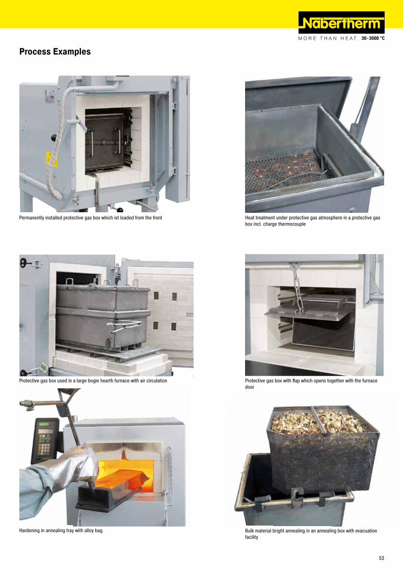
Permanently installed protective gas box which ist loaded from the front Heat treatment under protective gas atmosphere in a protective gas box incl. charge thermocouple
Protective gas box used in a large bogie hearth furnace with air circulation Protective gas box with flap which opens together with the furnace door
Hardening in annealing tray with alloy bag Bulk material bright annealing in an annealing box with evacuation facility
Process Examples
53

Chamber Furnaces with Brick Insulation or Fiber Insulation
The chamber furnaces LH 15/12 - LF 120/14 have been trusted for many years as professional chamber furnaces. These furnaces are available with either a robust insulation of light refractory bricks (LH models) or with a combination insulation of refractory bricks in the corners and low heat storage, quickly cooling fiber material (LF models). With a wide variety of optional equipment, these chamber furnaces can be optimally adapted to your processes.
� Tmax 1200 °C, 1300 °C, or 1400 °C � Dual shell housing with rear ventilation, provides for low shell temperatures � High furnace chamber with five-sided heating for very good temperature uniformity � Heating elements on support tubes ensure free heat radiation and a long service life � Controller mounted on furnace door and removable for comfortable operation � Protection of bottom heating and flat stacking surface provided by embedded SiC plate in the floor � LH models: multi-layered, fiber-free insulation of light refractory bricks and special backup insulation � LF models: high-quality non-classified fiber insulation with corner bricks for shorter heating and cooling times � Door with brick-on-brick seal, hand fitted � Short heating times due to high installed power � Self-supporting arch for high stability and greatest possible protection against dust � Quick lock on door � Motor driven exhaust air flap � Freely adjustable air slide intake in furnace floor � Base included � Defined application within the constraints of the operating instructions � NTLog Basic for Nabertherm controller: recording of process data with USB-flash drive � Controls description see page 88
Additional equipment � Parallel swinging door, pivots away from operator, for opening when hot � Lift door with electro-mechanic linear drive � Separate wall-mounting or floor standing cabinet for switchgear
Cooling fan in combination with motor-dri-ven exhaust air flap to reduce cooling time
Gas supply system for non-flammable protective or reaction gases
Chamber furnace LH 30/14
LH 60/12 with manual lift door and protective gas box for non-flammable protective or reactive gases
54
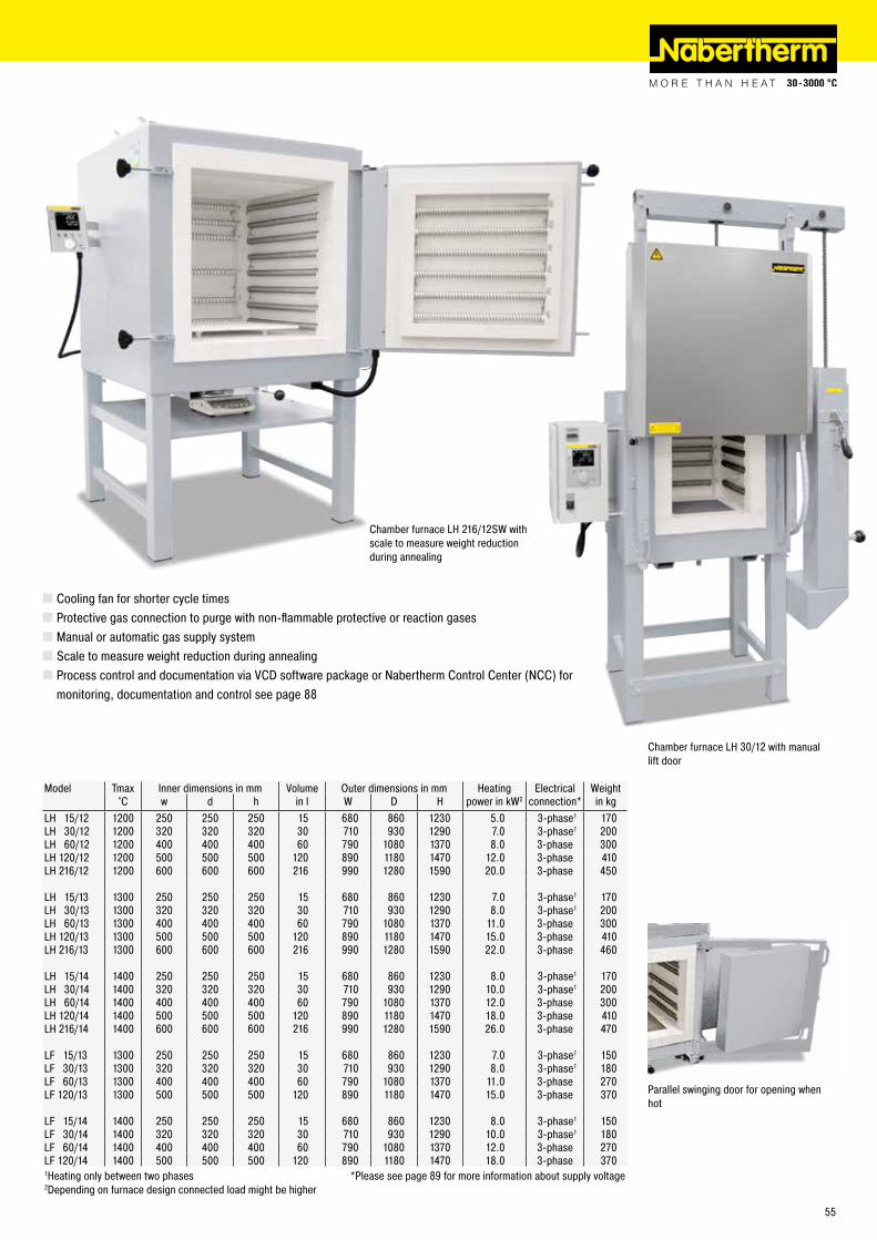
Parallel swinging door for opening whenhot
� Cooling fan for shorter cycle times � Protective gas connection to purge with non-flammable protective or reaction gases � Manual or automatic gas supply system � Scale to measure weight reduction during annealing � Process control and documentation via VCD software package or Nabertherm Control Center (NCC) for monitoring, documentation and control see page 88
Model Tmax Inner dimensions in mm Volume Outer dimensions in mm Heating Electrical Weight°C w d h in l W D H power in kW2 connection* in kg
LH 15/12 1200 250 250 250 15 680 860 1230 5.0 3-phase1 170LH 30/12 1200 320 320 320 30 710 930 1290 7.0 3-phase1 200LH 60/12 1200 400 400 400 60 790 1080 1370 8.0 3-phase 300LH 120/12 1200 500 500 500 120 890 1180 1470 12.0 3-phase 410LH 216/12 1200 600 600 600 216 990 1280 1590 20.0 3-phase 450
LH 15/13 1300 250 250 250 15 680 860 1230 7.0 3-phase1 170LH 30/13 1300 320 320 320 30 710 930 1290 8.0 3-phase1 200LH 60/13 1300 400 400 400 60 790 1080 1370 11.0 3-phase 300LH 120/13 1300 500 500 500 120 890 1180 1470 15.0 3-phase 410LH 216/13 1300 600 600 600 216 990 1280 1590 22.0 3-phase 460
LH 15/14 1400 250 250 250 15 680 860 1230 8.0 3-phase1 170LH 30/14 1400 320 320 320 30 710 930 1290 10.0 3-phase1 200LH 60/14 1400 400 400 400 60 790 1080 1370 12.0 3-phase 300LH 120/14 1400 500 500 500 120 890 1180 1470 18.0 3-phase 410LH 216/14 1400 600 600 600 216 990 1280 1590 26.0 3-phase 470
LF 15/13 1300 250 250 250 15 680 860 1230 7.0 3-phase1 150LF 30/13 1300 320 320 320 30 710 930 1290 8.0 3-phase1 180LF 60/13 1300 400 400 400 60 790 1080 1370 11.0 3-phase 270LF 120/13 1300 500 500 500 120 890 1180 1470 15.0 3-phase 370
LF 15/14 1400 250 250 250 15 680 860 1230 8.0 3-phase1 150LF 30/14 1400 320 320 320 30 710 930 1290 10.0 3-phase1 180LF 60/14 1400 400 400 400 60 790 1080 1370 12.0 3-phase 270LF 120/14 1400 500 500 500 120 890 1180 1470 18.0 3-phase 3701Heating only between two phases *Please see page 89 for more information about supply voltage2Depending on furnace design connected load might be higher
Chamber furnace LH 216/12SW with scale to measure weight reduction during annealing
Chamber furnace LH 30/12 with manual lift door
55

Due to the cubic interior of the LH chamber furnaces and the corresponding protective gas boxes, these furnaces are ideally suited for higher batches. Gassing boxes for the LH models have a standard charge thermocuple, which can be used, for example, for charge control. The protective gas inlet and outlet is routed through the furnace collar in the case of a furnace with a swivel door on the left and through the lower furnace collar in the lift-door configuration.
Protective Gas Boxes for Models LH 15/.. - LH 216/..
Article no. Furnace Inner dimensions in mm Outer dimensions in mm1 Charging methodw d h W D H of the box
631001276 LH 15/.. 100 100 100 165 182 166 draw hook631001277 LH 30/.. 170 170 170 235 252 236 draw hook631001278 LH 60/.. 250 250 250 315 332 316 draw hook631001279 LH 120/.. 350 350 350 415 411 441 draw hook631001280 LH 216/.. 450 450 400 514 535 554 charging stackerArticle no. 601655055, 1 set of fiber insulation cord, 5 strips of 610 mm each 1 Without pipingWork space = box inner dimensions: - 30 mm to all sidesLarger boxes and custom dimensions available upon request
These boxes have a lid for charging from above, protective gas inlet and outlet.
� Tmax 1100 °C � For non-combustible protective and reactive gases argon, nitrogen and forming gas (observe national regulations) � Protective gas box with fiber seal and cover with locks, inert gas introduction via a pipe into the bottom of the box � Protective gas connection via quick coupling with hose connector (inner diameter 9 mm) � Piping for gas inlet and outlet through the furnace collar � Heat-resistant alloy 314 (AISI)/(DIN material no. 1.4841) � Charge thermocouple type K for temperature display or charge control
Additional equipment � Starting from LH 30/.. a charging cart is recommended see page 78 � Digital temperature display see page 69 � Gas supply systems see page 74 � Extended gas piping for the use of smaller boxes in larger furnace models � Draw hook see page 77 � Charging stacker see page 79Protective gas box for furnaces with hinged
door
Protective Gas Boxes with Charging from the FrontDesign as the described protective gas boxes, but with charging from the front. These protective gas boxes remain in the oven and are equipped with a lid that can be opened to the front. After the lid has been opened, the batch can be removed directly.
Article no. Furnace Inner dimensions in mm Outer dimensions in mm1 Charging methodw d h W D H of the box
631001310 LH 15/.. 100 100 100 170 148 194 -631001311 LH 30/.. 170 170 170 240 218 264 -631001312 LH 60/.. 250 250 250 320 298 344 -631001313 LH 120/.. 350 350 350 420 398 444 -Article no. 601655055, 1 set of fiber insulation cord, 5 strips of 610 mm each 1 Without pipingWork space = box inner dimensions: - 30 mm to all sidesLarger boxes and custom dimensions available upon request
Protective gas box which stays in the furnace
56
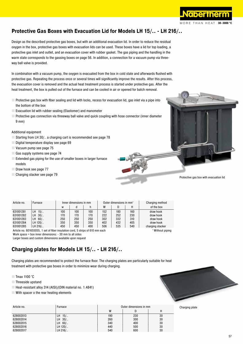
Design as the described protective gas boxes, but with an additional evacuation lid. In order to reduce the residual oxygen in the box, protective gas boxes with evacuation lids can be used. These boxes have a lid for top loading, a protective gas inlet and outlet, and an evacuation cover with rubber gasket. The gas piping and the handling in the warm state corresponds to the gassing boxes on page 56. In addition, a connection for a vacuum pump via three-way ball valve is provided.
In combination with a vacuum pump, the oxygen is evacuated from the box in cold state and afterwards flushed with protective gas. Repeating the process once or several times will significantly improve the results. After this process, the evacuation cover is removed and the actual heat treatment process is started under protective gas. After the heat treatment, the box is pulled out of the furnace and can be cooled in air or opened for batch removal.
� Protective gas box with fiber sealing and lid with locks, recess for evacuation lid, gas inlet via a pipe into the bottom of the box � Evacuation lid with rubber sealing (Elastomer) and manometer � Protective gas connection via threeway ball valve and quick coupling with hose connector (inner diameter 9 mm)
Additional equipment � Starting from LH 30/.. a charging cart is recommended see page 78 � Digital temperature display see page 69 � Vacuum pump see page 75 � Gas supply systems see page 74 � Extended gas piping for the use of smaller boxes in larger furnace models � Draw hook see page 77 � Charging stacker see page 79
Article no. Furnace Inner dimensions in mm Outer dimensions in mm1 Charging methodw d h W D H of the box
631001281 LH 15/.. 100 100 100 152 180 160 draw hook631001282 LH 30/.. 170 170 170 222 252 230 draw hook631001283 LH 60/.. 250 250 250 302 332 310 draw hook631001284 LH 120/.. 350 350 350 402 432 405 draw hook631001285 LH 216/.. 450 450 400 506 535 540 charging stackerArticle no. 601655055, 1 set of fiber insulation cord, 5 strips of 610 mm each 1 Without pipingWork space = box inner dimensions: - 30 mm to all sidesLarger boxes and custom dimensions available upon request
Protective gas box with evacuation lid
Charging plates are recommended to protect the furnace floor. The charging plates are particularly suitable for heat treatment with protective gas boxes in order to minimize wear during charging.
� Tmax 1100 °C � Threeside upstand � Heat-resistant alloy 314 (AISI)/(DIN material no. 1.4841) �With spacer o the rear heating elements
Article no. Furnace Outer dimensions in mmW D H
628002013 LH 15/.. 190 230 30628002014 LH 30/.. 260 300 30628002015 LH 60/.. 340 400 30628002016 LH 120/.. 440 500 30628002017 LH 216/.. 540 600 30
Charging plate
Protective Gas Boxes with Evacuation Lid for Models LH 15/.. - LH 216/..
Charging plates for Models LH 15/.. - LH 216/..
57

Model Tmax Inner dimensions in mm Volume Outer dimensions in mm Connected Electrical Weight°C w d h in l W D H load kW connection* in kg
NW 150 1300 430 530 620 150 790 1150 1600 11.0 3-phase 400NW 200 1300 500 530 720 200 860 1150 1700 15.0 3-phase 460NW 300 1300 550 700 780 300 910 1320 1760 20.0 3-phase 560NW 440 1300 600 750 1000 450 1000 1400 1830 30.0 3-phase 970NW 660 1300 600 1100 1000 660 1000 1750 1830 40.0 3-phase 1180NW 1000 1300 800 1000 1250 1000 1390 1760 2000 57.0 3-phase 1800 *Please see page 89 for more information about supply voltage
Chamber furnace NW 440 with free traver-sing bogie
The NW chamber furnaces enable simple charging for cold-cold processes. The heat treatment can take place under air or under non-flammable protective gases with a protective gas box or protective gas hood. With a drawer mechanism (NW 150 - NW 300/H) the furnace table can be easily pulled out of the chamber furnace. The larger models NW 440 - NW 1000/H are designed as shuttle furnace with completely free traversing bogie. Free access in front of the furnace allows for a simplified and clear charging.
� Tmax 1300 °C, 1100 °C with protective gas box (additional equipment) � Dual shell housing, galvanized steel sheets � Double-walled door with front made of textured stainless steel � Controller mounted on furnace door and removable for comfortable operation (up to model NW 440) � Heating from five sides with special arrangement of heating elements for optimum temperature uniformity
Chamber Furnaces with Drawer Bottom or as a Bogie
� Heating elements of support tubes provide for free radiation of the heat � Multi-layer insulation with light-weight refractory bricks and high-quality, energy-saving backing insulation
� Vaulted ceiling � Furnace table can be pulled-out as drawer (NW 150 - NW 300) � From chamber furnace NW 440 bogie on four castors (two with brakes) which can be pulled out completely. Accession assistance and removable drawbar for bogie � SiC-floor plate protects floor elements and provides a level setting surface � Door sealing grinded by hand (brick on brick); NW 150 - NW 300 � Semi-automatic air inlet flap closes the air inlet at a temperature which can be set in the controller for NW 150 - NW 300 � Exhaust air outlet in the ceiling, motor driven exhaust air flap for chamber furnaces NW 440 - NW 1000 � Comfortable charging height with base of 800 mm (chamber furnaces NW 440 - NW 1000 = 500 mm) � Defined application within the constraints of the operating instructions � NTLog for Nabertherm controller: recording of process data with USB-flash drive � Controls description see page 88
Additional equipment � Protective gas boxes and hoods � Manual or automatic gas supply system � Process control and documentation via VCD software package or Nabertherm Control Center (NCC) for monitoring, documentation and control see page 88
Chamber furnace NW 300 with pulled-out furnace table
58

Protective Gas HoodsProtective gas hoods consist of a and a bottom with a sealing profile as well as protective gas inlet and outlet. After charging the bottom in front of the oven in cold condition, the hood is put on and the drawer or the car is pushed back into the oven.
Design as protective gas boxes, but � Gassing hood with eye for raising the hood by crane � Hood bottom with sealing � Piping for gas inlet and outlet at the hood through the furnace collar
Additional equipment for protective gas boxes and hoods � Digital temperature display see page 69 � Gas supply systems see page 74
Chamber furnace NW 200 with protective gas box
Protective gas box for similar furnace
Furnace Article no. Inner dimensions in mm Article no. Inner dimensions in mm ChargingProtective gas box w d h Protective gas hood w d h the furnace
NW 150 631001329 330 420 400 631001334 300 360 400 DrawerNW 200 631001330 400 420 500 631001335 370 360 450 DrawerNW 300 631001331 450 550 550 631001336 420 530 500 DrawerNW 440 631001332 500 600 750 631001337 470 580 550 On a bogieNW 660 631001333 500 750 750 631001338 470 750 550 On a bogieNW 1000 on request on request On a bogieArticle no. 601655055, 1 set of fiber insulation cord, 5 strips of 610 mm eachWork space = box inner dimensions: - 30 mm to all sidesLarger boxes and custom dimensions available upon request
Protective Gas Boxes and Protective Gas Hoods for Chamber Furnaces NW 150 - NW 1000
Two automatic gas sypply systems, con-nected with each other
Protective Gas BoxesThese protective gas boxes have a cover with a sealing profile as well as a protective gas inlet and outlet. They are pulled out of the furnace in cold condition and charged from above.
� Tmax 1100 °C � For non-combustible protective and reactive gases argon, nitrogen and forming gas (observe national regulations) � Protective gas box with fiber seal and cover with locks, inert gas introduction via a pipe into the bottom of the box � Protective gas connection via quick coupling with hose connector (inner diameter 9 mm) � Piping for gas inlet and outlet through the furnace collar � Forklift receptive � Heat-resistant alloy 314 (AISI)/(DIN material no. 1.4841) � Charge thermocouple type K for temperature display or charge control
59
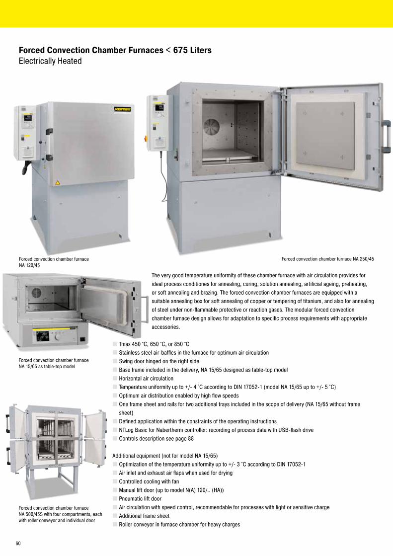
Forced Convection Chamber Furnaces < 675 Liters Electrically Heated
The very good temperature uniformity of these chamber furnace with air circulation provides for ideal process conditiones for annealing, curing, solution annealing, artificial ageing, preheating, or soft annealing and brazing. The forced convection chamber furnaces are equipped with a suitable annealing box for soft annealing of copper or tempering of titanium, and also for annealing of steel under non-flammable protective or reaction gases. The modular forced convection chamber furnace design allows for adaptation to specific process requirements with appropriate accessories.
� Tmax 450 °C, 650 °C, or 850 °C � Stainless steel air-baffles in the furnace for optimum air circulation � Swing door hinged on the right side � Base frame included in the delivery, NA 15/65 designed as table-top model � Horizontal air circulation � Temperature uniformity up to +/- 4 °C according to DIN 17052-1 (model NA 15/65 up to +/- 5 °C) � Optimum air distribution enabled by high flow speeds � One frame sheet and rails for two additional trays included in the scope of delivery (NA 15/65 without frame sheet) � Defined application within the constraints of the operating instructions � NTLog Basic for Nabertherm controller: recording of process data with USB-flash drive � Controls description see page 88
Additional equipment (not for model NA 15/65) � Optimization of the temperature uniformity up to +/- 3 °C according to DIN 17052-1 � Air inlet and exhaust air flaps when used for drying � Controlled cooling with fan � Manual lift door (up to model N(A) 120/.. (HA)) � Pneumatic lift door � Air circulation with speed control, recommendable for processes with light or sensitive charge � Additional frame sheet � Roller conveyor in furnace chamber for heavy charges
Forced convection chamber furnace NA 15/65 as table-top model
Forced convection chamber furnace NA 120/45
Forced convection chamber furnace NA 250/45
Forced convection chamber furnace NA 500/45S with four compartments, each with roller conveyor and individual door
60

Roller conveyor in forced convection chamber furnace N 250/85HA
Model Tmax Inner dimensions in mm Volume Outer dimensions in mm Heating Electrical Weight Heat-up time5 Cool-down time5 from Tmaxpower in kW3 to Tmax to 150 °C in minues
°C w d h in l W D H NA/NA .. LS connection* in kg in minutes Flaps4 Fan cooling4
NA 30/45(LS) 450 290 420 260 30 1040 1290 1385 3.0 / 9.0 1(3)-phase 285 120 120 30NA 60/45(LS) 450 350 500 350 60 1100 1370 1475 6.0 / 12.0 3-phase 350 120 240 30NA 120/45(LS) 450 450 600 450 120 1250 1550 1550 9.0 / 18.0 3-phase 460 60 240 30NA 250/45(LS) 450 600 750 600 250 1350 1650 1725 12.0 / 24.0 3-phase 590 60 120 30NA 500/45(LS) 450 750 1000 750 500 1550 1900 1820 18.0 / 24.0 3-phase 750 60 240 30NA 675/45(LS) 450 750 1200 750 675 1550 2100 1820 24.0 / 30.0 3-phase 900 90 270 60
NA 15/651 650 295 340 170 15 470 790 460 2.8 1-phase 60 40 - -NA 30/65 650 290 420 260 30 870 1290 1385 5.0 3-phase2 285 120 270 60N A 60/65 650 350 500 350 60 910 1390 1475 9.0 3-phase 350 120 270 60NA 120/65 650 450 600 450 120 990 1470 1550 12.0 3-phase 460 60 300 60NA 250/65 650 600 750 600 250 1170 1650 1680 20.0 3-phase 590 90 270 60NA 500/65 650 750 1000 750 500 1290 1890 1825 27.0 3-phase 750 60 240 60NA 675/65 650 750 1200 750 675 1290 2100 1825 27.0 3-phase 900 90 270 90
N 30/85 HA 850 290 420 260 30 607 + 255 1175 1315 5.5 3-phase2 195 180 900 90N 60/85 HA 850 350 500 350 60 667 + 255 1250 1400 9.0 3-phase 240 150 900 120N 120/85 HA 850 450 600 450 120 767 + 255 1350 1500 13.0 3-phase 310 150 900 120N 250/85 HA 850 600 750 600 250 1002 + 255 1636 1860 20.0 3-phase 610 180 900 180N 500/85 HA 850 750 1000 750 500 1152 + 255 1886 2010 30.0 3-phase 1030 180 900 210N 675/85 HA 850 750 1200 750 675 1152 + 255 2100 2010 30.0 3-phase 1350 210 900 210
1Table-top model see page 60 *Please see page 89 for more information about supply voltage2Heating only between two phases 4Additional equipment3Depending on furnace design connected load might be higher 5Empty furnace
� Annealing boxes � Feed and charging aids � Safety technology according to EN 1539 (NFPA 86) (models NA .. LS) for charges containing solvents � Inlets, measuring frames and thermocouples for TUS measurements charge or comparative measurements � Charge control � Process control and documentation via VCD software package or Nabertherm Control Center (NCC) for monitoring, documentation and control see page 88
Forced convection chamber furnace N 250/85HA with quenching bath
Forced convection chamber furnace NA 500/65
61

Protective Gas Boxes for Models NA 30/45 - N 500/85HA
For the heat treatment, workpieces are placed in the box, the lid is locked using the sealing locks and flushed with protective gas outside the furnace for some time and then placed in the furnace. Depending on the weight, a charging cart (page 30) is recommended.
Basic Version � For non-combustible protective and reactive gases argon, nitrogen and forming gas (observe national regulations) � Protective gas box with fiber seal and cover with locks, inert gas introduction via a pipe into the bottom of the box � Protective gas connection via quick coupling with hose connector (inner diameter 9 mm) � Piping for gas inlet and outlet through the furnace collar � Models N 250/..HA, NA 250/.., N 500/..HA und NA 500/.. will be delivered without bootom frame sheet � Heat-resistant alloy: 309 (AISI)/(DIN material no. 1.4828) � Charge thermocouple type K for temperature display or charge control
Additional equipment � Digital temperature display see page 69 � Gas supply systems see page 74 � Extended gas piping for the use of smaller boxes in larger furnace models � Draw hook see page 77 � Charging cart see page 78
Article no. Furnace Inner dimensions in mm Outer dimensions in mm1 Charging method(Furnace with hinged door) (Furnace with lift door) w d h W D H of the box631000410 631000763 NA 30/.., N 30/..HA 220 320 160 282 376 242 draw hook631000411 631000764 NA 60/.., N 60/..HA 270 420 260 336 460 340 draw hook631000412 631000765 NA 120/.., N 120/..HA 350 520 340 436 560 430 draw hook631000413 631000766 NA 250/.., N 250/..HA 480 630 460 546 680 600 charging stacker631000414 631000767 NA 500/.., N 500/..HA 630 780 610 696 836 760 charging stackerArticle no. 601655055, 1 set of fiber insulation cord, 5 strips of 610 mm each 1 Without pipingWork space = box inner dimensions: - 30 mm to all sidesLarger boxes and custom dimensions available upon request
Protective gas box with insertations
Protective gas box with extended piping for usage in a large furnace model
Forced convection chamber furnace N 250/85 HA with protective gas box
62
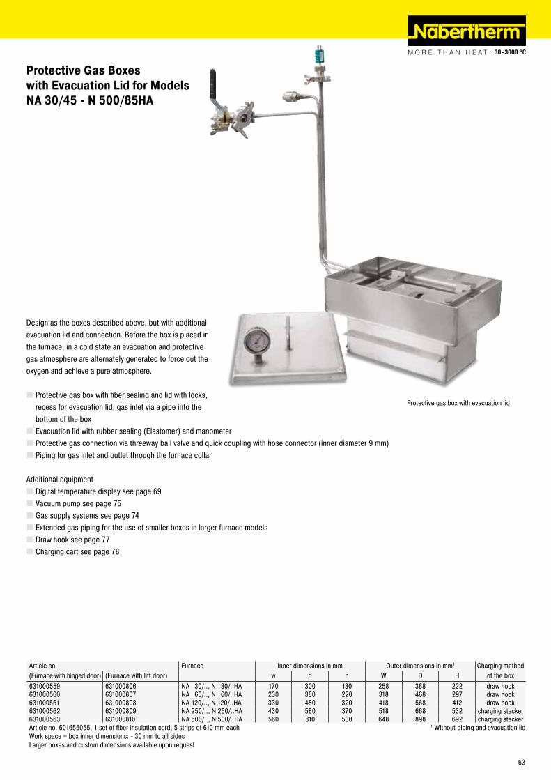
Design as the boxes described above, but with additional evacuation lid and connection. Before the box is placed in the furnace, in a cold state an evacuation and protective gas atmosphere are alternately generated to force out the oxygen and achieve a pure atmosphere.
� Protective gas box with fiber sealing and lid with locks, recess for evacuation lid, gas inlet via a pipe into the bottom of the box � Evacuation lid with rubber sealing (Elastomer) and manometer � Protective gas connection via threeway ball valve and quick coupling with hose connector (inner diameter 9 mm) � Piping for gas inlet and outlet through the furnace collar
Additional equipment � Digital temperature display see page 69 � Vacuum pump see page 75 � Gas supply systems see page 74 � Extended gas piping for the use of smaller boxes in larger furnace models � Draw hook see page 77 � Charging cart see page 78
Article no. Furnace Inner dimensions in mm Outer dimensions in mm1 Charging method(Furnace with hinged door) (Furnace with lift door) w d h W D H of the box631000559 631000806 NA 30/.., N 30/..HA 170 300 130 258 388 222 draw hook631000560 631000807 NA 60/.., N 60/..HA 230 380 220 318 468 297 draw hook631000561 631000808 NA 120/.., N 120/..HA 330 480 320 418 568 412 draw hook631000562 631000809 NA 250/.., N 250/..HA 430 580 370 518 668 532 charging stacker631000563 631000810 NA 500/.., N 500/..HA 560 810 530 648 898 692 charging stackerArticle no. 601655055, 1 set of fiber insulation cord, 5 strips of 610 mm each 1 Without piping and evacuation lidWork space = box inner dimensions: - 30 mm to all sidesLarger boxes and custom dimensions available upon request
Protective gas box with evacuation lid
Protective Gas Boxes with Evacuation Lid for Models NA 30/45 - N 500/85HA
63
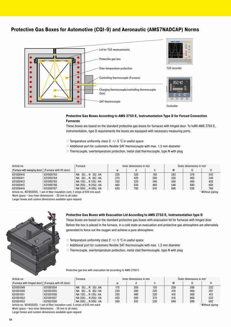
Protective Gas Boxes According to AMS 2750 E, Instrumentation Type D for Forced Convection FurnacesThese boxes are based on the standard protective gas boxes for furnaces with hinged door. To fulfill AMS 2750 E, instrumentation, type D requirements the boxes are equipped with necessary measuring ports.
� Temperature uniformity class 2: +/- 5 °C in useful space � Additional port for customers flexible SAT thermocouple with max. 1,5 mm diameter � Thermcouple, overtemperature protection, metal clad thermocouple, type N with plug
Article no. Furnace Inner dimensions in mm Outer dimensions in mm1
(Furnace with swinging door) (Furnace with lift door) w d h W D H631000410 631000763 NA 30/.., N 30/..HA 220 320 160 282 376 242631000411 631000764 NA 60/.., N 60/..HA 270 420 260 336 460 340631000412 631000765 NA 120/.., N 120/..HA 350 520 340 436 560 430631000413 631000766 NA 250/.., N 250/..HA 480 630 460 546 680 600631000414 631000767 NA 500/.., N 500/..HA 630 780 610 696 836 760Article no. 601655055, 1 set of fiber insulation cord, 5 strips of 610 mm each 1 Without pipingWork space = box inner dimensions: - 30 mm to all sidesLarger boxes and custom dimensions available upon request
Protective Gas Boxes with Evacuation Lid According to AMS 2750 E, Instrumentation type DThese boxes are based on the standard protective gas boxes with evacuation lid for furnaces with hinged door. Before the box is placed in the furnace, in a cold state an evacuation and protective gas atmosphere are alternately generated to force out the oxygen and achieve a pure atmosphere.
� Temperature uniformity class 2: +/- 5 °C in useful space � Additional port for customers flexible SAT thermocouple with max. 1,5 mm diameter � Thermcouple, overtemperature protection, metal clad thermocouple, type N with plug
Article no. Furnace Inner dimensions in mm Outer dimensions in mm1
(Furnace with hinged door) (Furnace with lift door) w d h W D H631001049 631001054 NA 30/.., N 30/..HA 170 300 130 258 388 222631001050 631001055 NA 60/.., N 60/..HA 230 380 220 318 468 297631001051 631001056 NA 120/.., N 120/..HA 330 480 320 418 568 412631001052 631001057 NA 250/.., N 250/..HA 430 580 370 518 668 532631001053 631001058 NA 500/.., N 500/..HA 560 810 530 648 898 692Article no. 601655055, 1 set of fiber insulation cord, 5 strips of 610 mm each 1 Without pipingWork space = box inner dimensions: - 30 mm to all sidesLarger boxes and custom dimensions available upon request
Protective gas box with evacuation lid according to AMS 2750 E
Protective Gas Boxes for Automotive (CQI-9) and Aeronautic (AMS7NADCAP) Norms
TUS recorder
Controller
Lid for TUS measurements
Protective gas box
Over-temperature protection
Controlling thermocouple (Furnace)
Charging thermocouple/controlling thermocouple (box)
SAT thermocouple
64

Model Tmax Inner dimensions in mm Volume Outer dimensions in mm Heating Electrical Weight°C w d h in l W D H power in kW3 connection* in kg
NA 30/45 I 450 290 420 260 30 1040 1290 1385 3.0 1(3)-phase 285NA 60/45 I 450 350 500 350 60 1100 1370 1475 6.0 3-phase 350NA 120/45 I 450 450 600 450 120 1250 1550 1550 9.0 3-phase 460NA 250/45 I 450 600 750 600 250 1350 1650 1725 12.0 3-phase 590NA 500/45 I 450 750 1000 750 500 1550 1900 1820 18.0 3-phase 750NA 675/45 I 450 750 1200 750 675 1550 2100 1820 24.0 3-phase 900
NA 15/65 I1 650 295 340 170 15 470 790 460 2.8 1-phase 60NA 30/65 I 650 290 420 260 30 870 1290 1385 5.0 3-phase2 285N A 60/65 I (SI) 650 350 500 350 60 910 1390 1475 9.0 3-phase 350NA 120/65 I (SI) 650 450 600 450 120 990 1470 1550 12.0 3-phase 460NA 250/65 I (SI) 650 600 750 600 250 1170 1650 1680 20.0 3-phase 590NA 500/65 I (SI) 650 750 1000 750 500 1290 1890 1825 27.0 3-phase 750NA 675/65 I 650 750 1200 750 675 1290 2100 1825 27.0 3-phase 900
1Table-top model *Please see page 89 for more information about supply voltage2Heating only between two phases 3Depending on furnace design connected load might be higher
Sealed forced convection chamber furnaces are suitable if a heat treatment process up to 650 °C requires a protective gas atmosphere that does not have to be completely oxygen free.
The difference between the two variants is that the I-model only has a sealed outer housing while the SI-model has a welded inner box, which further reduces the residual oxygen concentration.
NA-I design Like forced convection chamber furnaces < 675 l (page 60) with the following changes
� Tmax 450 °C and 650 °C � Silicone door seal � Furnace housing sealed with silicone � Protective gas connection in the back wall � Defined application within the constraints of the operating instructions � Residual oxygen concentration < 1 % depending on the volume and type of protective gas � For non-flammable protective and reaction gases such as argon, nitrogen, and forming gas (national regulations must be considered)
NA-SI design Additional features
� Tmax 650 °C �Welded inner housing � 2-sided heating and air circulation � Door sealed with seal gas � Sealed connection to circulation motor � Gas inlet via circulator shaft � Defined application within the constraints of the operating instructions � Residual oxygen concentration to 0.1 % depending on the volume and type of protective gas � For non-flammable protective and reaction gases such as argon, nitrogen, and forming gas (national regulations must be considered)
Sealed Forced Convection Chamber Furnaces NA-I and NA-SI
Forced convection chamber furnace NA 120/65 I
Forced convection chamber furnace NA 15/65 I as tabletop model with manual gas supply system
65
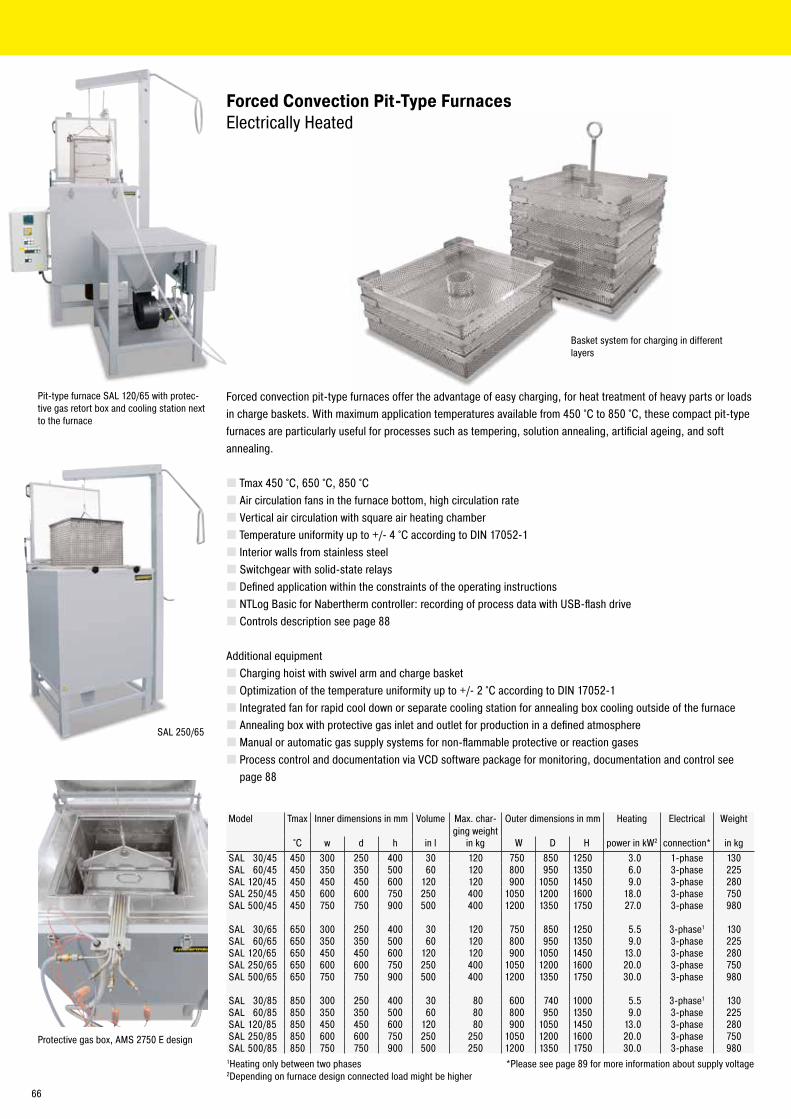
SAL 250/65
Forced Convection Pit-Type Furnaces Electrically Heated
Forced convection pit-type furnaces offer the advantage of easy charging, for heat treatment of heavy parts or loads in charge baskets. With maximum application temperatures available from 450 °C to 850 °C, these compact pit-type furnaces are particularly useful for processes such as tempering, solution annealing, artificial ageing, and soft annealing.
� Tmax 450 °C, 650 °C, 850 °C � Air circulation fans in the furnace bottom, high circulation rate � Vertical air circulation with square air heating chamber � Temperature uniformity up to +/- 4 °C according to DIN 17052-1 � Interior walls from stainless steel � Switchgear with solid-state relays � Defined application within the constraints of the operating instructions � NTLog Basic for Nabertherm controller: recording of process data with USB-flash drive � Controls description see page 88
Additional equipment � Charging hoist with swivel arm and charge basket � Optimization of the temperature uniformity up to +/- 2 °C according to DIN 17052-1 � Integrated fan for rapid cool down or separate cooling station for annealing box cooling outside of the furnace � Annealing box with protective gas inlet and outlet for production in a defined atmosphere � Manual or automatic gas supply systems for non-flammable protective or reaction gases � Process control and documentation via VCD software package for monitoring, documentation and control see page 88
Basket system for charging in different layers
Pit-type furnace SAL 120/65 with protec-tive gas retort box and cooling station next to the furnace
Protective gas box, AMS 2750 E design
Model Tmax Inner dimensions in mm Volume Max. char-ging weight
Outer dimensions in mm Heating Electrical Weight
°C w d h in l in kg W D H power in kW2 connection* in kgSAL 30/45 450 300 250 400 30 120 750 850 1250 3.0 1-phase 130SAL 60/45 450 350 350 500 60 120 800 950 1350 6.0 3-phase 225SAL 120/45 450 450 450 600 120 120 900 1050 1450 9.0 3-phase 280SAL 250/45 450 600 600 750 250 400 1050 1200 1600 18.0 3-phase 750SAL 500/45 450 750 750 900 500 400 1200 1350 1750 27.0 3-phase 980
SAL 30/65 650 300 250 400 30 120 750 850 1250 5.5 3-phase1 130SAL 60/65 650 350 350 500 60 120 800 950 1350 9.0 3-phase 225SAL 120/65 650 450 450 600 120 120 900 1050 1450 13.0 3-phase 280SAL 250/65 650 600 600 750 250 400 1050 1200 1600 20.0 3-phase 750SAL 500/65 650 750 750 900 500 400 1200 1350 1750 30.0 3-phase 980
SAL 30/85 850 300 250 400 30 80 600 740 1000 5.5 3-phase1 130SAL 60/85 850 350 350 500 60 80 800 950 1350 9.0 3-phase 225SAL 120/85 850 450 450 600 120 80 900 1050 1450 13.0 3-phase 280SAL 250/85 850 600 600 750 250 250 1050 1200 1600 20.0 3-phase 750SAL 500/85 850 750 750 900 500 250 1200 1350 1750 30.0 3-phase 980
1Heating only between two phases *Please see page 89 for more information about supply voltage2Depending on furnace design connected load might be higher
66
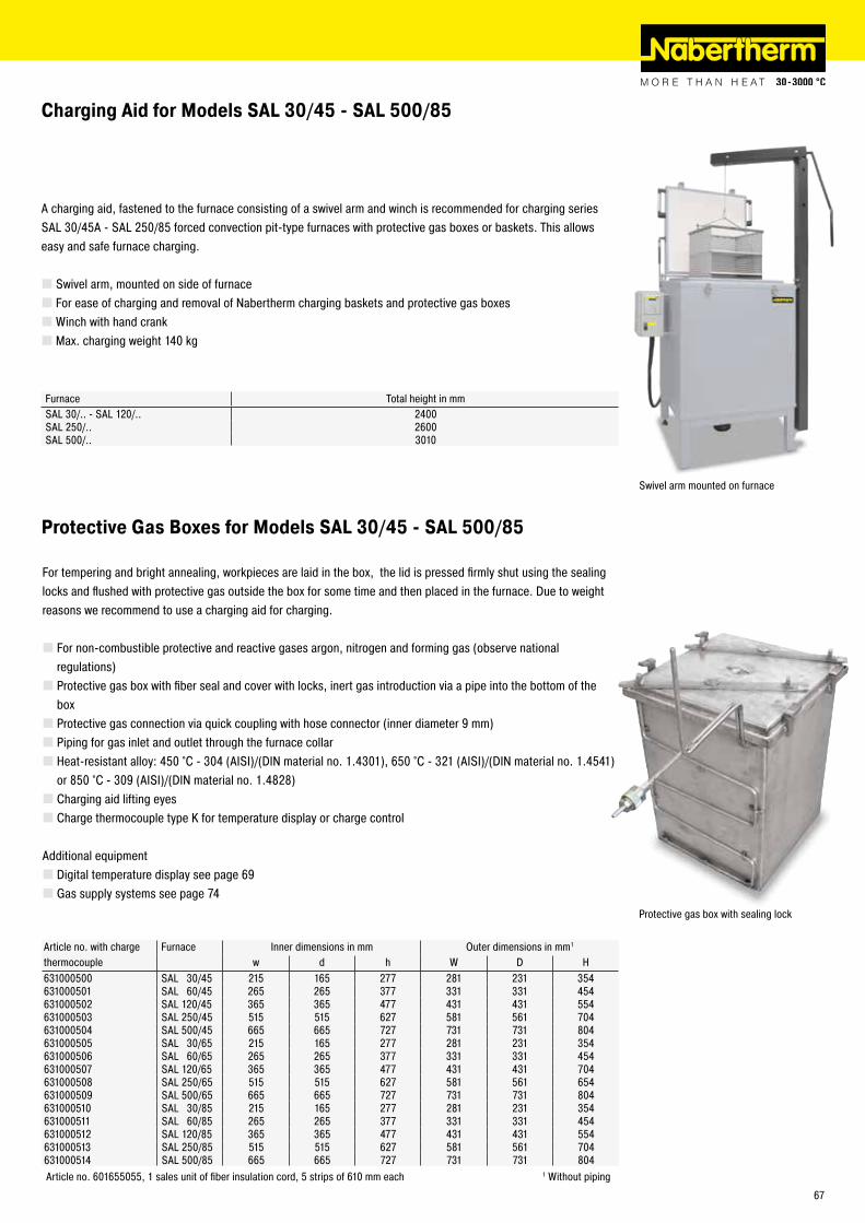
Protective Gas Boxes for Models SAL 30/45 - SAL 500/85
For tempering and bright annealing, workpieces are laid in the box, the lid is pressed firmly shut using the sealing locks and flushed with protective gas outside the box for some time and then placed in the furnace. Due to weight reasons we recommend to use a charging aid for charging.
� For non-combustible protective and reactive gases argon, nitrogen and forming gas (observe national regulations) � Protective gas box with fiber seal and cover with locks, inert gas introduction via a pipe into the bottom of the box � Protective gas connection via quick coupling with hose connector (inner diameter 9 mm) � Piping for gas inlet and outlet through the furnace collar � Heat-resistant alloy: 450 °C - 304 (AISI)/(DIN material no. 1.4301), 650 °C - 321 (AISI)/(DIN material no. 1.4541) or 850 °C - 309 (AISI)/(DIN material no. 1.4828) � Charging aid lifting eyes � Charge thermocouple type K for temperature display or charge control
Additional equipment � Digital temperature display see page 69 � Gas supply systems see page 74
A charging aid, fastened to the furnace consisting of a swivel arm and winch is recommended for charging series SAL 30/45A - SAL 250/85 forced convection pit-type furnaces with protective gas boxes or baskets. This allows easy and safe furnace charging.
� Swivel arm, mounted on side of furnace � For ease of charging and removal of Nabertherm charging baskets and protective gas boxes �Winch with hand crank � Max. charging weight 140 kg
Charging Aid for Models SAL 30/45 - SAL 500/85
Furnace Total height in mmSAL 30/.. - SAL 120/.. 2400SAL 250/.. 2600SAL 500/.. 3010
Article no. with charge Furnace Inner dimensions in mm Outer dimensions in mm1
thermocouple w d h W D H631000500 SAL 30/45 215 165 277 281 231 354631000501 SAL 60/45 265 265 377 331 331 454631000502 SAL 120/45 365 365 477 431 431 554631000503 SAL 250/45 515 515 627 581 561 704631000504 SAL 500/45 665 665 727 731 731 804631000505 SAL 30/65 215 165 277 281 231 354631000506 SAL 60/65 265 265 377 331 331 454631000507 SAL 120/65 365 365 477 431 431 704631000508 SAL 250/65 515 515 627 581 561 654631000509 SAL 500/65 665 665 727 731 731 804631000510 SAL 30/85 215 165 277 281 231 354631000511 SAL 60/85 265 265 377 331 331 454631000512 SAL 120/85 365 365 477 431 431 554631000513 SAL 250/85 515 515 627 581 561 704631000514 SAL 500/85 665 665 727 731 731 804Article no. 601655055, 1 sales unit of fiber insulation cord, 5 strips of 610 mm each 1 Without piping
Swivel arm mounted on furnace
Protective gas box with sealing lock
67
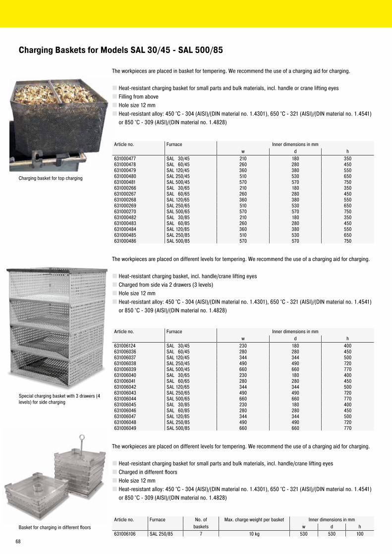
The workpieces are placed on different levels for tempering. We recommend the use of a charging aid for charging.
� Heat-resistant charging basket, incl. handle/crane lifting eyes � Charged from side via 2 drawers (3 levels) � Hole size 12 mm � Heat-resistant alloy: 450 °C - 304 (AISI)/(DIN material no. 1.4301), 650 °C - 321 (AISI)/(DIN material no. 1.4541) or 850 °C - 309 (AISI)/(DIN material no. 1.4828)
The workpieces are placed in basket for tempering. We recommend the use of a charging aid for charging.
� Heat-resistant charging basket for small parts and bulk materials, incl. handle or crane lifting eyes � Filling from above � Hole size 12 mm � Heat-resistant alloy: 450 °C - 304 (AISI)/(DIN material no. 1.4301), 650 °C - 321 (AISI)/(DIN material no. 1.4541) or 850 °C - 309 (AISI)/(DIN material no. 1.4828)
Charging Baskets for Models SAL 30/45 - SAL 500/85
Charging basket for top charging
Article no. Furnace Inner dimensions in mmw d h
631000477 SAL 30/45 210 180 350631000478 SAL 60/45 260 280 450631000479 SAL 120/45 360 380 550631000480 SAL 250/45 510 530 650631000481 SAL 500/45 570 570 750631000266 SAL 30/65 210 180 350631000267 SAL 60/65 260 280 450631000268 SAL 120/65 360 380 550631000269 SAL 250/65 510 530 650631000270 SAL 500/65 570 570 750631000482 SAL 30/85 210 180 350631000483 SAL 60/85 260 280 450631000484 SAL 120/85 360 380 550631000485 SAL 250/85 510 530 650631000486 SAL 500/85 570 570 750
Article no. Furnace Inner dimensions in mmw d h
631006124 SAL 30/45 230 180 400631006036 SAL 60/45 280 280 450631006037 SAL 120/45 344 344 500631006038 SAL 250/45 490 490 720631006039 SAL 500/45 660 660 770631006040 SAL 30/65 230 180 400631006041 SAL 60/65 280 280 450631006042 SAL 120/65 344 344 500631006043 SAL 250/65 490 490 720631006044 SAL 500/65 660 660 770631006045 SAL 30/85 230 180 400631006046 SAL 60/85 280 280 450631006047 SAL 120/85 344 344 500631006048 SAL 250/85 490 490 720631006049 SAL 500/85 660 660 770
Special charging basket with 3 drawers (4 levels) for side charging
The workpieces are placed on different levels for tempering. We recommend the use of a charging aid for charging.
� Heat-resistant charging basket for small parts and bulk materials, incl. handle/crane lifting eyes � Charged in different floors � Hole size 12 mm � Heat-resistant alloy: 450 °C - 304 (AISI)/(DIN material no. 1.4301), 650 °C - 321 (AISI)/(DIN material no. 1.4541) or 850 °C - 309 (AISI)/(DIN material no. 1.4828)
Article no. Furnace No. of Max. charge weight per basket Inner dimensions in mmbaskets w d h
631006106 SAL 250/85 7 10 kg 530 530 100Basket for charging in different floors
68
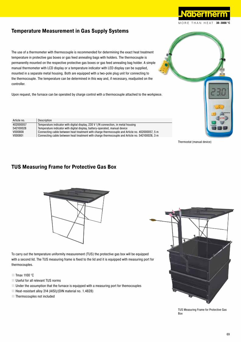
Temperature Measurement in Gas Supply Systems
The use of a thermometer with thermocouple is recommended for determining the exact heat treatment temperature in protective gas boxes or gas feed annealing bags with holders. The thermocouple is permanently mounted on the respective protective gas boxes or gas feed annealing bag holder. A simple manual thermometer with LCD display or a temperature indicator with LED display can be supplied, mounted in a separate metal housing. Both are equipped with a two-pole plug unit for connecting to the thermocouple. The temperature can be determined in this way and, if necessary, readjusted on the controller.
Upon request, the furnace can be operated by charge control with a thermocouple attached to the workpiece.
Thermostat (manual device)
Article no. Description402000057 Temperature indicator with digital display, 230 V 1/N connection, in metal housing542100028 Temperature indicator with digital display, battery-operated, manual deviceV000808 Connecting cable between heat treatment with charge thermocouple and Article no. 402000057, 5 mV000801 Connecting cable between heat treatment with charge thermocouple and Article no. 542100028, 3 m
To carry out the temperature uniformity measurement (TUS) the protective gas box will be equipped with a second lid. The TUS measuring frame is fixed to the lid and it is equipped with measuring port for thermocouples.
� Tmax 1100 °C � Useful for all relevant TUS norms � Under the assumption that the furnace is equipped with a measuring port for themocouples � Heat-resistant alloy 314 (AISI)/(DIN material no. 1.4828) � Thermocouples not included
TUS Measuring Frame for Protective Gas Box
TUS Measuring Frame for Protective Gas Box
69
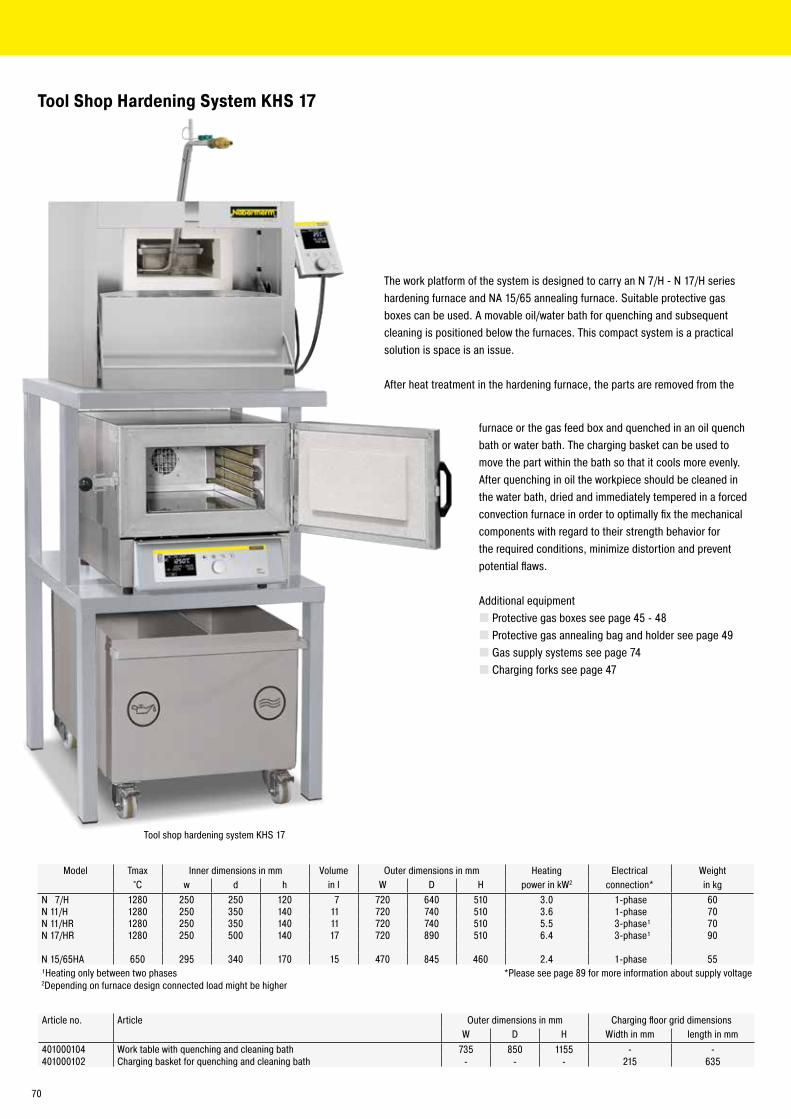
Tool Shop Hardening System KHS 17
Model Tmax Inner dimensions in mm Volume Outer dimensions in mm Heating Electrical Weight°C w d h in l W D H power in kW2 connection* in kg
N 7/H 1280 250 250 120 7 720 640 510 3.0 1-phase 60N 11/H 1280 250 350 140 11 720 740 510 3.6 1-phase 70N 11/HR 1280 250 350 140 11 720 740 510 5.5 3-phase¹ 70N 17/HR 1280 250 500 140 17 720 890 510 6.4 3-phase¹ 90
N 15/65HA 650 295 340 170 15 470 845 460 2.4 1-phase 55¹Heating only between two phases *Please see page 89 for more information about supply voltage2Depending on furnace design connected load might be higher
Article no. Article Outer dimensions in mm Charging floor grid dimensions W D H Width in mm length in mm
401000104 Work table with quenching and cleaning bath 735 850 1155 - -401000102 Charging basket for quenching and cleaning bath - - - 215 635
The work platform of the system is designed to carry an N 7/H - N 17/H series hardening furnace and NA 15/65 annealing furnace. Suitable protective gas boxes can be used. A movable oil/water bath for quenching and subsequent cleaning is positioned below the furnaces. This compact system is a practical solution is space is an issue.
After heat treatment in the hardening furnace, the parts are removed from the
furnace or the gas feed box and quenched in an oil quench bath or water bath. The charging basket can be used to move the part within the bath so that it cools more evenly. After quenching in oil the workpiece should be cleaned in the water bath, dried and immediately tempered in a forced convection furnace in order to optimally fix the mechanical components with regard to their strength behavior for the required conditions, minimize distortion and prevent potential flaws.
Additional equipment � Protective gas boxes see page 45 - 48 � Protective gas annealing bag and holder see page 49 � Gas supply systems see page 74 � Charging forks see page 47
Tool shop hardening system KHS 17
70
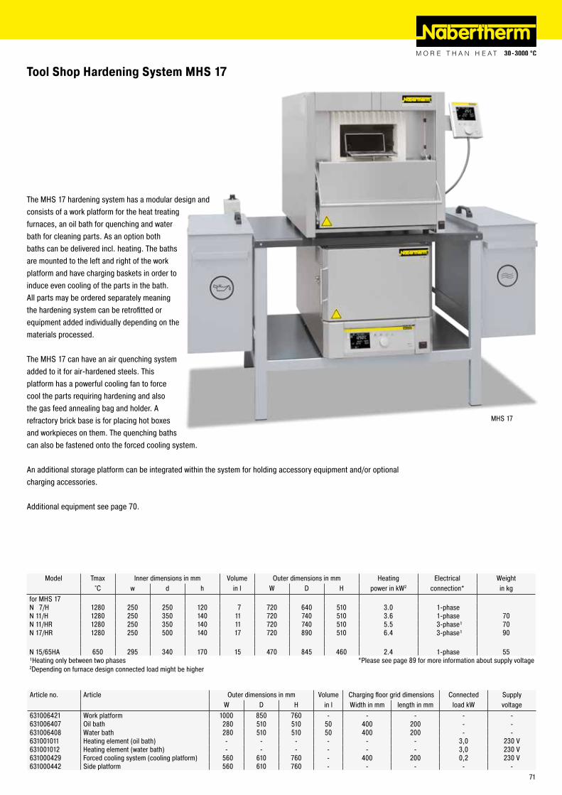
MHS 17
Tool Shop Hardening System MHS 17
The MHS 17 hardening system has a modular design and consists of a work platform for the heat treating furnaces, an oil bath for quenching and water bath for cleaning parts. As an option both baths can be delivered incl. heating. The baths are mounted to the left and right of the work platform and have charging baskets in order to induce even cooling of the parts in the bath. All parts may be ordered separately meaning the hardening system can be retrofitted or equipment added individually depending on the materials processed.
The MHS 17 can have an air quenching system added to it for air-hardened steels. This platform has a powerful cooling fan to force cool the parts requiring hardening and also the gas feed annealing bag and holder. A refractory brick base is for placing hot boxes and workpieces on them. The quenching baths can also be fastened onto the forced cooling system.
An additional storage platform can be integrated within the system for holding accessory equipment and/or optional charging accessories.
Additional equipment see page 70.
Article no. Article Outer dimensions in mm Volume Charging floor grid dimensions Connected SupplyW D H in l Width in mm length in mm load kW voltage
631006421 Work platform 1000 850 760 - - - - -631006407 Oil bath 280 510 510 50 400 200 - -631006408 Water bath 280 510 510 50 400 200 - -631001011 Heating element (oil bath) - - - - - - 3,0 230 V631001012 Heating element (water bath) - - - - - - 3,0 230 V631000429 Forced cooling system (cooling platform) 560 610 760 - 400 200 0,2 230 V631000442 Side platform 560 610 760 - - - - -
Model Tmax Inner dimensions in mm Volume Outer dimensions in mm Heating Electrical Weight°C w d h in l W D H power in kW2 connection* in kg
for MHS 17N 7/H 1280 250 250 120 7 720 640 510 3.0 1-phaseN 11/H 1280 250 350 140 11 720 740 510 3.6 1-phase 70N 11/HR 1280 250 350 140 11 720 740 510 5.5 3-phase¹ 70N 17/HR 1280 250 500 140 17 720 890 510 6.4 3-phase¹ 90
N 15/65HA 650 295 340 170 15 470 845 460 2.4 1-phase 55¹Heating only between two phases *Please see page 89 for more information about supply voltage2Depending on furnace design connected load might be higher
71

Model Tmax Inner dimensions in mm Charging height Outer dimensions in mm Heating Electrical Weight°C w d h in mm W D H power in kW2 connection* in kg
MHS 31 N 31/H 1280 350 350 250 900 1040 1100 1340 15 3-phase 210NA 30/65 650 290 420 260 900 870 1290 1385 5 3-phase¹ 285Quenching bath Q 50 - 200 170 - 700 350 350 700 - - -Heating element - - - - - - - - 3 1-phase -
MHS 41 N 41/H 1280 350 500 250 900 1040 1250 1340 15 3-phase 260NA 60/65 650 350 500 350 900 910 1390 1475 9 3-phase 350Quenching bath Q 50 - 200 170 - 700 350 350 700 - - -Heating element - - - - - - - - 3 1-phase -
MHS 61 N 61/H 1280 350 750 250 900 1040 1500 1350 20 3-phase 400NA 60/65 650 350 500 350 900 910 1390 1475 9 3-phase 350Quenching bath Q 50 - 200 170 - 700 350 350 700 - - -Heating element - - - - - - - - 3 1-phase -
Acces- Charging cart CW1 - - - - 880 - 920 330 1100 880 - 920 - - -sories Charging cart CWK1 - - - - 880 - 920 330 1100 880 - 920 0,2 1-phase -
Side platform - 600 600 900 600 600 900 - - -Protective gas box N 31/H 1100 280 230 200 - 316 304 226 - - -Protective gas box N 41/H 1100 280 380 200 - 316 454 226 - - -
¹Heating only between two phases *Please see page 89 for more information about supply voltage2Depending on furnace design connected load might be higher
Tool Shop Hardening Systems MHS 31, MHS 41 and MHS 61
These toolshop hardening systems are suitable for hardening larger components in air or under a protective gas atmosphere. The systems can be assembled from a chamber furnace, a forced convection furnace, a protective gas box with a gas supply via a solenoid valve, a charging plate to protect the furnace floor, and a quenching bath with heating element. During the heat treatment under protective gas, the process starts with the flushing of the batch in the protective gas box by means of protective gas. Subsequently, annealing is carried out in the chamber furnace at a lower process flushing rate. The chamber furnace is opened after the annealing process and the batch is removed from the protective gas box to be quenched in the preheated quench bath. The final annealing process takes place in the forced convection furnace. For easier charging, we recommend the use of optional charging aids such as pull hooks and charging trolleys.
The toolshop hardening systems are an assembly of furnaces and accessories from our standard range. All components can also be ordered separately.
Additional equipment � Draw hook see page 77 � Charging cart see page 78
72

Protective Gas Hardening System SHS 41
Protective gas hardening system with furnace N 41/H
This compact, semi-automatic system is suitable for hardening in a protective gas atmosphere followed by quenching of the workpiece in oil. In this way, even larger parts can be annealed under a protective gas and quenched. It consists of a chamber furnace N 41/H hardening furnace with a pneumatic door opening and charging plates as well as an oil quench bath on rollers with an integrated pneumatic lowering unit, a floor grid with gas hood, a holding unit for the gas hood as well as a rim exhaust with flame trap.
The workpiece is placed on the floor grid and covered with the gas hood. After preflushing with protective gas, the gas hood is pushed with the floor grid into the chamber furnace. After the heat treatment is completed, the workload is pulled out of the furnace onto the lowering unit. The hood remains above the quenching bath while the charging floor grid is lowered pneumatically. In order to obtain best quenching results, the pneumatic lowering unit is moved up and down in the oil quench bath. After completion, the workload is moved into unloading position.
This low cost system can be used for hardening processes which otherwise could only be handled in complex furnace systems.
� Chamber furnace N 41/H � Pneumatic pedal switch operated door opening � Charging plate � Oil quench bath on rollers � Pneumatic lowering unit � Heating of oil quench bath � Oil temperature display � Charging floor grid and gas hood � Holding unit for gas hood � Manual protective gas unit see page 74 � Draw hook see page 77 � Safety equipment consisting of rim exhaust with flame trap and oil steam separator
Additional equipment � Suction hood �Water bath
Furnace Tmax Inner dimensions in mm Volume Outer dimensions in mm Heating Electrical WeightModel °C w d h in l W D H power in kW2 connection* in kgN 41/H¹ 1280 350 500 250 40 1040 1250 1340 15.0 3-phase 260¹Furnace description see page 43 *Please see page 89 for more information about supply voltage2Depending on furnace design connected load might be higher
Article no. Protective gas hood size in mm Oil quench bath max. load max. quench Preflush Process Heating power Electricalhardening system W D H size in liters Weight yield/h rate flush rate oil bath/kW connection*
- SHS 41 260 360 180 400 25 kg 20 kg 20 - 25 10 - 15 6.0 3-phase631006104 Gas hood (spare part)
*Please see page 89 for more information about supply voltage
73

Gas Supply Systems
Protective GasesProtective gases are used to force oxygen out of the gas feed boxes mentioned above. Make sure to use protective gases behaving neutrally toward the heat treated part. The protective gases should be inert, meaning no chemical bonding should occur with the workpiece or the furnace and no reactions should be enduced.
In many cases, nitrogen is used as protective gas (lighter than air). Our experience shows that nitrogen does not always lead to sufficient results. A longer preflush time must also be used.
Better results are achieved by adding a mixture of nitrogen and adding some hydrogen. Hydrogen acts as a reducing constituent and reacts with the oxygen. This gas mixture is known as forming gas and available in stores. Experience has shown that adding 5 % hydrogen to the nitrogen leads to good results. According to the EU material safety data sheet this mixture is considered as not flammable. National regulations, however, must be observed. This gas can be obtained in premixed form. No measures must be taken in advance to prevent explosions.
If the workpiece has an affinity to hydrogen, argon used as protective gas can lead to good results.
Argon is a gas which is heavier than air. This makes it relatively easy to fill the protective gas containers. Forming gas with added hydrogen (depending on the country law up to a ration of 98/2) is lighter, but it has the advantage of burning at higher temperatures and therefore binds with the oxygen. Even in a cold state, the leaking hydrogen transports the oxygen very easily out of the container.
For gas mixtures with hydrogen or other combustible gases, the valid safety regulations must always be observed. If the mixture is declared as combustible, the furnace, provided it is a gas tight version, can be fitted with a corresponding safety system.
Always make sure that the room is properly ventilated when working with protective gases. Country-specific safety regulations must also be followed.
Article no. Type of gas Flow ratel/min
631000309 Ar 0 - 30631000310 N2 0 - 30631000311 Non-flammable forming gas 0 - 30Alternative connection threads on request
Pressure reducing valve with assembled flow meter
Manual Gas Feed Fitting for Bottles � Pressure reducing valve with assembled flow meter and attached pressure gauge indicating the bottle pressure The assembled variable area flow meter ensures good readability of the amount used � Connection: screw connection for bottle � Exit: hose connection (inner diameter 9 mm) � 200 bar intake pressure, 4 bar outlet pressure � Incl. 4 m connecting hose to the furnace
74

Automatic Gas Supply System for two different Flushing Quantities, e.g. high Volume Pre-flushing and low Volume for ongoing OperationConsisting of:
� Switching system with 3-step switch for gas inlet Off/Manual/Automatic via "Extra" function of respective controller, timer for switching from large gas quantity to small gas quantity. Gas feed stops at when program quits � Automatic gas feed panel with pressure reducer, two adjustable flow meters and two solenoid valves, preinstalled conduit and wiring attached to furnace from the side on an assembly plate.
� Connection: hose connection (inner diameter 9 mm) � Exit: hose connection (inner diameter 9 mm) � Max. 10 bar intake pressure, max. 300 mbar outlet pressure � Incl. connecting hose between furnace and protective gas box or gas connection � Available only in combination with furnace or switchgear
Article no. Type of gas Flow ratel/min
631000316 Ar 4 - 80631000200 N2 4 - 80631000315 Non-flammable forming gas 4 - 80
Gas Feed Fitting with Solenoid Valve � Solenoid valve mounted on the furnace, controlled using the controller "Extra" function � Connection: screw connection for bottle � Exit: hose connection (inner diameter 9 mm) � 200 bar intake pressure, 4 bar outlet pressure � Incl. 4 m connecting hose to the furnace � Available only in combination with furnace or switchgear
Article no. Type of gas Flow ratel/min
631000379 Ar 0 - 30631000380 N2 0 - 30631000381 Non-flammable forming gas 0 - 30Alternative connection threads on request
Automatic gas supply system for two flushing quantities
Vacuum Pump
Vacuum pump
Oil sealed rotary vane vacuum pump for universal use within the low vacuum range. Highly compact and low noise construction. Manometer included in delivery.
� Sliding vane rotary pump with sucking capacity of max. 16 m³/h � 0,5 mbar absolute � Connection hose made of stainless steel 2000 mm � Connector KF16 � Manometer (-1/0.6 bar)
Article no. Outer dimensions in mm Connections on suction side
Connected Supply Nominal suction power
Suction capacity
W D H load voltage* m3 h m3 h-l601403057 280 315 200 3/4" 1/2" inner thread 0.55 kW 230 V 16 15*Article no. for other possible supply voltages on request
75

491041104 491041103 493000004
� Frontal heat protection � Open back � Velcro fastener on the back � Material Preox-Aramid-Aluminium � For radiated heat up to 1000 °C, max. 95 sec. � C3-classification according to EN 11612-C � Length 1300 mm
Frontal Protection Coat
Article no. Description699000325 Frontal Protection Coat, Size 54 (D), 1300 mm
� Specially insulated gloves for working with hot mechanical components and working near furnace
Gloves
Article no.: 491041101
Article no. Description Short-time contact temperature in °C491041101 Fiberglass finger glove, 380 mm long approx. 700491041102 Mitten, 280 mm long approx. 400491041103 Finger glove, 300 mm long approx. 400491041104 Fiberglass mitten, 380 mm long approx. 700493000004 Carbon-fiber finger glove, knitted approx. 650
� Light design with adjustable hat size � Plastic window, folds up
Heat-Resistant Face Mask
Article no. Description491037105 Heat-resistant face mask
76

� Various shapes and sizes for different applications and workpiece geometries � Handle length 600 mm, assuring sufficient distance from hot furnace chamber and for deep immersion length into quench bath
Hardening Tongs
Binding Wire
� For binding workpieces to allow easy removal from boxes � Annealed twice and safe from breakage during charging
Article no. Wire Ø in mm Container491036090 0.90 25 kg ring491036125 1.20 25 kg ring491036150 1.60 25 kg ring491036200 2.00 25 kg ring491036300 3.00 25 kg ring
Article no. Description491003001 Tongs with flat jaw suitable for hand forming491003002 Tongs with vertical mouth for lifting off floor491003003 Tongs with bent mouth, universal use491003004 Tongs with double-curve jaw, universal use491003005 Half round tongs, for round rod materials491003006 Knee tongs for larger rings with thick wall491003008 Handy universal tongs for small parts (handle length 500 mm)
Article no. Length in mm631000663 500631000593 750631000594 1000
Draw Hook
Article no.491003001
491003002
491003005
491003006
� For charging protective gas annealing bags with holder, annealing and protective gas boxes � Large handle, also easy to handle with glove
77
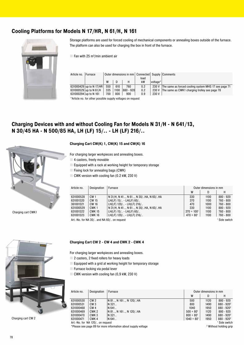
Charging Devices with and without Cooling Fan for Models N 31/H - N 641/13, N 30/45 HA - N 500/85 HA, LH (LF) 15/.. - LH (LF) 216/..
Charging Cart CW(K) 1, CW(K) 15 and CW(K) 16
For charging larger workpieces and annealing boxes. � 4 casters, freely movable � Equipped with a rack at working height for temporary storage � Fixing lock for annealing bags (CWK) � CWK version with cooling fan (0.2 kW, 230 V)
Charging Cart CW 2 - CW 4 and CWK 2 - CWK 4
For charging larger workpieces and annealing boxes. � 2 casters, 2 fixed rollers for heavy loads � Equipped with a grid at working height for temporary storage � Furnace locking via pedal lever � CWK version with cooling fan (0,9 kW, 230 V)
Article no. Designation Furnace Outer dimensions in mmW D H
631000528 CW 1 N 31/H, N 41.., N 61.., N 30/..HA, N 60/..HA 330 1100 880 - 920631001320 CW 15 LH(LF) 15/.. - LH(LF) 60/.. 370 1100 760 - 800361001321 CW 16 LH(LF) 120/.. - LH(LF) 216/.. 470 1000 760 - 800631000529 CWK 1 N 31/H, N 41.., N 61.., N 30/..HA, N 60/..HA 330 1100 880 - 920631001322 CWK 15 LH(LF) 15/.. - LH(LF) 60/.. 370 + 1001 1100 760 - 800631001323 CWK 16 LH(LF) 120/.. - LH(LF) 216/.. 470 + 801 1100 760 - 800Art.-No. for NA 30/.. and NA 60/.. on request 1 Side switch
Article no. Designation Furnace Outer dimensions in mmW D H
631000530 CW 2 N 81.., N 161.., N 120/..HA 500 1120 880 - 920631000531 CW 3 N 321.. 800 1490 880 - 9202
631000468 CW 4 N 641.. 1040 1950 880 - 9202
631000469 CWK 2 N 81.., N 161.., N 120/..HA 500 + 801 1120 880 - 920631000470 CWK 3 N 321.. 800 + 801 1490 880 - 9202
631000471 CWK 4 N 641.. 1040 + 801 1950 880 - 9202
Art.-No. for NA 120/.. on request 1 Side switch*Please see page 89 for more information about supply voltage 2 Without holding grip
Charging cart CW 2
Charging cart CWK1
Cooling Platforms for Models N 17/HR, N 61/H, N 161
Storage platforms are used for forced cooling of mechanical components or annealing boxes outside of the furnace. The platform can also be used for charging the box in front of the furnace.
� Fan with 25 m³/min ambient air
Article no. Furnace Outer dimensions in mm Connected load
Supply Comments
W D H kW voltage*631000429 up to N 17/HR 550 610 760 0.2 230 V The same as forced cooling system MHS 17 see page 71631000529 up to N 61/H 335 1100 880 - 920 0.2 230 V The same as CWK1 charging trolley see page 78631000294 up to N 161 700 800 900 0.9 230 V*Article no. for other possible supply voltages on request
78

Charging Cart WS 81 and WS 12
For charging of protective gas and annealing boxes. � 2 casters, 2 fixed rollers for heavy loads � Parallel guided lift, approx. 20 mm � Max. charging weight 80 kg � Guiding track, mounted at the furnace base frame � Guiding track and charging cart can be also ordered separately
Charging Stacker WS 81
Article no. Designation Furnace631000473 WS 81 N 81..631000695 WS 12 N 120/..HAArt.-No. for NA 120/.. on request
Charging Stacker WS 25 - WS 321
� Lifting device with hand winch � Compact construction with push bar and manual lifting device for easy and safe lifting � 2 casters, 2 fixed rollers � Adjustable loading fork width � Max. charging weight 500 kg � Guiding track, mounted at the furnace base frame � Guiding track and forklift can be also ordered separately
WS 50 charging stacker
Article no. Designation Furnace631000425 WS 161 N 161..631000370 WS 321 N 321..631000299 WS 25 N 250/..HA631000532 WS 50 N 500/..HAArt.-No. for NA 250/.. and NA 500/.. on request
WS 641 Charging Stacker
Design as charging stacker WS 25 - WS 321, but � Lifting device with manual hydraulic � Max. charging weight 700 kg
Charging stacker WS 641 with chamber furnace N 641 and guiding track at the base frame
Article no. Designation Furnace631000426 WS 641 N 641..
Guiding track at the base frame
79

Baths for quenching in oil or water as well as for cleaning and degreasing are available as single or double baths and are made of stainless steel. Oil quench bath assure highly even cooling of workpieces and are equipped with a lid to immediatley extinguish ignited oil. For optimal results, pre-tempering water baths for cleaning workpieces should have an appropriate degreasing additive mixed in to the water bath. An optional heating allows for a bath temperature of approx. 70 °C. All baths come with a charge carrier, supply and drain line.
The oil and water quench baths are combined within a single housing and separated by a sheet metal wall in the Q 200 D, Q 400 D and Q 600 D combination baths. The oil quench bath is slightly preheated by the heated water bath. A splash pan is installed in front of the combination bath. Charging aids are available as additional equipment. The Q 200 D combination bath comes with a charge carrier, for models Q 400 D and Q 600 D must be ordered extra. For greater quenchant performance, the baths can be equipped with oil coolers.
Quenching and Cleaning Baths
Article no. Bath Outer dimensions in mm Volume Quenchant max. loadW D H in l performance in kg/h weight in kg
101300050 Q 50 350 350 700 50 5 - 10 20101300040 Q 200 550 550 900 200 25 - 30 20
Article no. Heating element Connected Supply(optional) load kW voltage*
631001014 Q 50 3 230 V631001012 Q 200 6 400 V*Article no. for other possible supply voltages on request
Article no. Bath Outer dimensions in mm Volume in l max. loadW D H Oil/water weight in kg
101300100 Q 200 D 1200 700 900 200/125 20101300200 Q 400 D 1700 750 900 400/300 40101300300 Q 600 D 2100 900 900 600/450 60
Charging aid Total height Max. load weight Compressed air Connected Electricalmanual + electric in mm in kg in bar load kW connection1
Q 200 D 1800 20 6 - 9 - -Q 400 D 2480 40 - 0.3 1-phaseQ 600 D 2480 60 - 0.3 1-phase
Quenching bath Q 200 for quenching in oil or water
Quenching bath Q 400 D with manual charging aid
Heating element Connected Supplyload kW voltage*
Q 200 D 6 400 VQ 400 D 9 400 VQ 600 D 15 400 V*Other supply voltages possible on request
Oil cooler max. quenchant Connected Electricalperformance in kg/h load kW connection¹
Q 200 D approx. 100 0.55 3-phaseQ 400 D approx. 200 2.20 3-phaseQ 600 D approx. 300 2.20 3-phase¹Please see page 89 for more information about supply voltage
Oil cooler as additional equipment
80
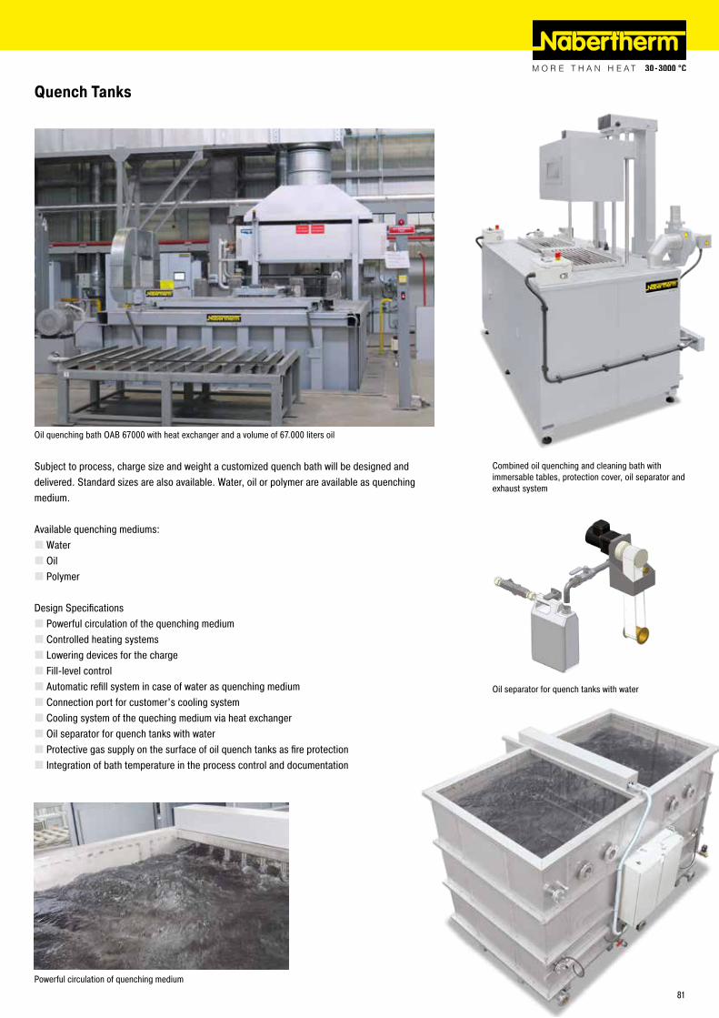
Quench Tanks
Subject to process, charge size and weight a customized quench bath will be designed and delivered. Standard sizes are also available. Water, oil or polymer are available as quenching medium.
Available quenching mediums: �Water � Oil � Polymer
Design Specifications � Powerful circulation of the quenching medium � Controlled heating systems � Lowering devices for the charge � Fill-level control � Automatic refill system in case of water as quenching medium � Connection port for customer’s cooling system � Cooling system of the queching medium via heat exchanger � Oil separator for quench tanks with water � Protective gas supply on the surface of oil quench tanks as fire protection � Integration of bath temperature in the process control and documentation
Powerful circulation of quenching medium
Oil separator for quench tanks with water
Combined oil quenching and cleaning bath with immersable tables, protection cover, oil separator and exhaust system
Oil quenching bath OAB 67000 with heat exchanger and a volume of 67.000 liters oil
81
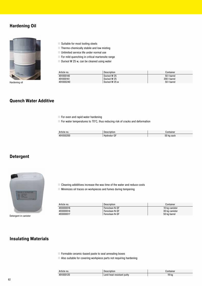
� Suitable for most tooling steels � Thermo-chemically stabile and low misting � Unlimited service life under normal use � For mild quenching in critical martensite range � Durixol W 25 w, can be cleaned using water
Hardening Oil
Quench Water Additive
� For even and rapid water hardening � For water temperatures to 70°C, thus reducing risk of cracks and deformation
� Cleaning addditives increase the was time of the water and reduce costs � Minimizes oil traces on workpieces and fumes during tempering
Article no. Description Container491000140 Durixol W 25 50 l barrel491000161 Durixol W 25 200 l barrel491000240 Durixol W 25 w 50 l barrel
Article no. Description Container491050200 Hydrodur GF 50 kg sack
Article no. Description Container493000016 Feroclean N-SF 10 kg canister493000014 Feroclean N-SF 30 kg canister493000017 Feroclean N-SF 50 kg barrel
Insulating Materials
� Formable ceramic-based paste to seal annealing boxes � Also suitable for covering workpiece parts not requiring hardening
Article no. Description Container491000120 Lenit heat-resistant putty 19 kg
Detergent
Hardening oil
Detergent in canister
82
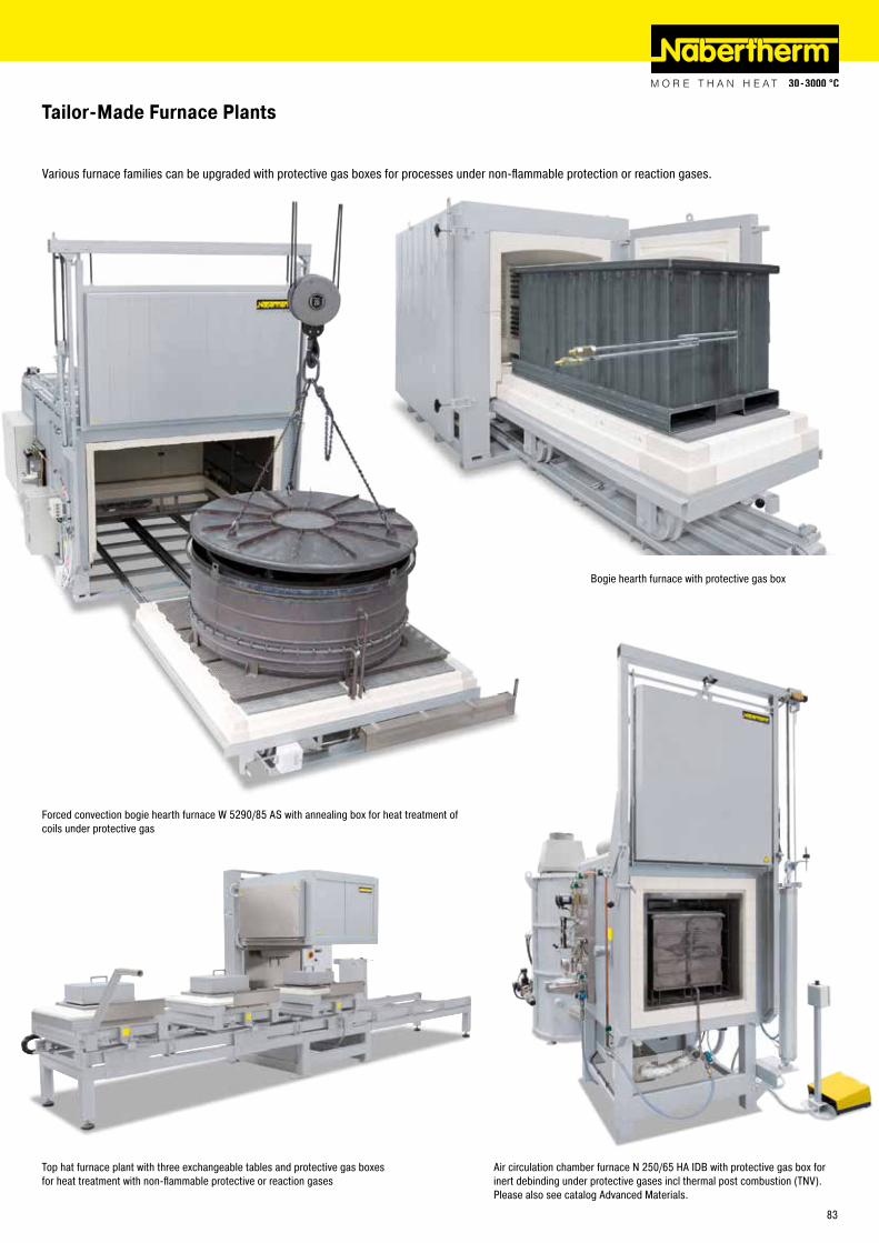
Forced convection bogie hearth furnace W 5290/85 AS with annealing box for heat treatment of coils under protective gas
Top hat furnace plant with three exchangeable tables and protective gas boxes for heat treatment with non-flammable protective or reaction gases
Air circulation chamber furnace N 250/65 HA IDB with protective gas box for inert debinding under protective gases incl thermal post combustion (TNV). Please also see catalog Advanced Materials.
Bogie hearth furnace with protective gas box
Tailor-Made Furnace Plants
Various furnace families can be upgraded with protective gas boxes for processes under non-flammable protection or reaction gases.
83

Temperature Uniformity and System Accuracy
Holding frame for measurement of tempe-rature uniformity
The system accuracy is defined by adding the tolerances of the controls, the thermo-couple and the work space
Deviation from measuring point to the average temperature in the work space e.g. +/-3 °C
Deviation of thermocouple, e.g. +/- 1.5 °CPrecision of the controls, e.g. +/- 1K
Temperature uniformity is defined as the maximum temperature deviation in the work space of the furnace. There is a general difference between the furnace chamber and the work space. The furnace chamber is the total volume available in the furnace. The work space is smaller than the furnace chamber and describes the volume which can be used for charging.
Specification of Temperature Uniformity in +/- K in the Standard FurnaceIn the standard design the temperature uniformity is specified in +/- K at a defined set-temperature with the work space of the empty furnace during the dwell time. In order to make a temperature uniformity survey the furnace should be calibrated accordingly. As standard our furnaces are not calibrated upon delivery.
Calibration of the Temperature Uniformity in +/- KIf an absolute temperature uniformity at a reference temperature or at a defined reference temperature range is required, the furnace must be calibrated appropriately. If, for example, a temperature uniformity of +/- 5 K at a set temperature of 750 °C is required, it means that measured temperatures may range from a minimum of 745 °C to a maximum of 755 °C in the work space.
System AccuracyTolerances may occur not only in the work space, they also exist with respect to the thermocouple and in the controls. If an absolute temperature uniformity in +/- K at a defined set temperature or within a defined reference working temperature range is required, the following measures have to be taken:
� Measurement of total temperature deviation of the measurement line from the controls to the thermocouple � Measurement of temperature uniformity within the work space at the reference temperature or within the reference temperature range � If necessary, an offset is set at the controls to adjust the displayed temperature at the controller to the real temperature in the furnace � Documentation of the measurement results in a protocol
Temperature Uniformity in the Work Space incl. ProtocolIn standard furnaces a temperature uniformity is guaranteed as +/- K without measurement of temperature uniformity. However, as additional feature, a temperature uniformity measurement at a reference temperature in the work space compliant with DIN 17052-1 can be ordered. Depending on the furnace model, a holding frame which is equivalent in size to the charge space is inserted into the furnace. This frame holds thermocouples at defined measurement positions (11 thermocouples with square cross-section, 9 thermocouple with circular cross-section). The temperature uniformity meassurement is performed at a reference temperature specified by the customer at a pre-defined dwell time. If necessary, different reference temperatures or a defined reference working temperature range can also be calibrated.
Pluggable frame for measurement for forced convection chamber furnace N 7920/45 HAS
84

Standards such as the AMS 2750 E (Aerospace Material Specifications) are applicable for the industrial processing of high-quality materials. They define industry-specific requirements for heat treatment. Today, the AMS 2750 E and derivative standards such as AMS 2770 for the heat treatment of aluminum are the guidlines for the aerospace industry. After the introduction of the CQI-9, the automotive industry has also committed to submit heat treatment processes to stricter rules. These standards describe in detail the requirements applicable to thermal processing plants.
� Temperature uniformity in the work space (TUS) � Instrumentation (definition of measurement and control systems) � Calibration of the measurement system (IT) from the controller via the measurement line to the thermocouple. � Inspections of system accuracy (SAT) � Documentation of the inspection cycles
Norm compliance is necessary to ensure that the required quality standard of the manufactured components can also be reproduced in series. For this reason, extensive and repeated inspections as well as controls of the instrumentation, including the relevant documentation, are required.
Furnace Class and Instrumentation Requirements of the AMS 2750 EDepending on the quality requirements of heat treatment job the customer specifies instrumentation type and the temperature uniformity class. The instrumentation type describes the necessary combination of the applied control, recording media as well as thermocouples. The temperature uniformity of the furnace and the class of the selected instrumentation are defined based on the required furnace class. The higher the requirements are set for the furnace class the more precise the instrumentation must be.
AMS 2750 E, NADCAP, CQI-9
Measurement set-up in a high-temperature furnace
Measurement set-up in an annealing furnace
Instrumentation Type Furnace class
Temperature uniformityA B C D E °C °F
Each control zone has a thermocouple connected to the controller x x x x x 1 +/- 3 +/- 5Recording of the temperature measured by the control thermocou-ple x x x x 2 +/- 6 +/- 10
Sensors for recording the coldest and hottest spots x x 3 +/- 8 +/- 15Each control zone has a charge thermocouple with recording system x x 4 +/- 10 +/- 20Each control zone has an over-temperature protection unit x x x x 5 +/- 14 +/- 25
6 +/- 24 +/- 50
Regular InspectionsThe furnace or the heat treatment plant must be designed so that the requirements of the AMS 2750 E can be met and be reproduced. The standard also requires the inspection intervals for the instrumentation (SAT = System Accuracy Test) and the temperature uniformity of the furnace (TUS = Temperature Uniformity Survey). The SAT/TUS tests must be performed by the customer with measuring devices and sensors which operate independently of the furnace instrumentation.
Nabertherm ServicesThe suitable furnace model for the corresponding heat treatment can be designed based on the process, the charge, the required furnace class and the type of instrumentation. Depending on the required specs, alternative solutions can be offered.
� Furnace designs, which meet standards, following customer specifications regarding furnace class and instrumentation, incl. gauge connections for repeated customer inspections at regular intervals. No consideration of requirements with respect to documentation � Data recording devices (e.g., temperature recorder) for TUS and/or SAT measurements see page 90 � Data recording, visualization, time management via the Nabertherm Control Center (NCC), based on Siemens WinCC software see page 88 � Commissioning at site, incl. the first TUS and SAT inspection � Connection of existing furnace plant to meet norm requirements � Documentation of the complete process chain in line with the corresponding norm
85
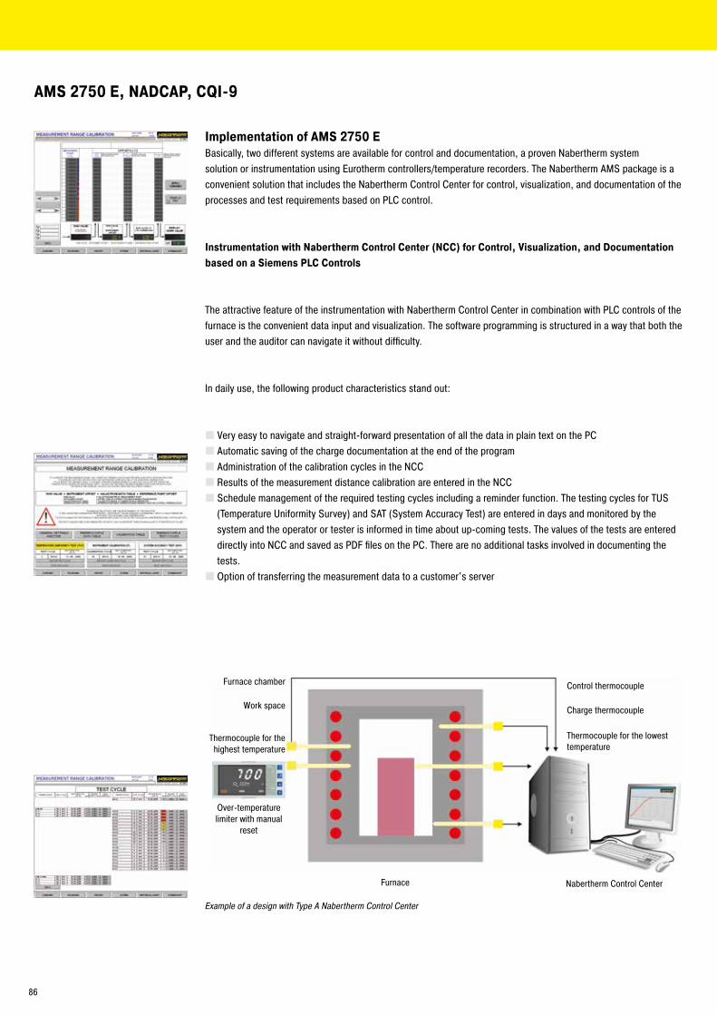
Implementation of AMS 2750 EBasically, two different systems are available for control and documentation, a proven Nabertherm system solution or instrumentation using Eurotherm controllers/temperature recorders. The Nabertherm AMS package is a convenient solution that includes the Nabertherm Control Center for control, visualization, and documentation of the processes and test requirements based on PLC control.
Instrumentation with Nabertherm Control Center (NCC) for Control, Visualization, and Documentation based on a Siemens PLC Controls
The attractive feature of the instrumentation with Nabertherm Control Center in combination with PLC controls of the furnace is the convenient data input and visualization. The software programming is structured in a way that both the user and the auditor can navigate it without difficulty.
In daily use, the following product characteristics stand out:
� Very easy to navigate and straight-forward presentation of all the data in plain text on the PC � Automatic saving of the charge documentation at the end of the program � Administration of the calibration cycles in the NCC � Results of the measurement distance calibration are entered in the NCC � Schedule management of the required testing cycles including a reminder function. The testing cycles for TUS (Temperature Uniformity Survey) and SAT (System Accuracy Test) are entered in days and monitored by the system and the operator or tester is informed in time about up-coming tests. The values of the tests are entered directly into NCC and saved as PDF files on the PC. There are no additional tasks involved in documenting the tests. � Option of transferring the measurement data to a customer's server
Example of a design with Type A Nabertherm Control Center
Furnace chamber
Work space
Control thermocouple
Over-temperature limiter with manual
reset
Thermocouple for the highest temperature
Thermocouple for the lowest temperature
Furnace
Charge thermocouple
Nabertherm Control Center
AMS 2750 E, NADCAP, CQI-9
86
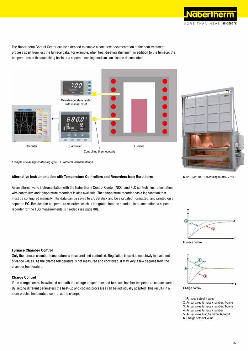
The Nabertherm Control Center can be extended to enable a complete documentation of the heat treatment process apart from just the furnace data. For example, when heat-treating aluminum, in addition to the furnace, the temperatures in the quenching basin or a separate cooling medium can also be documented.
Example of a design containing Type D Eurotherm instrumentation
Recorder Controller
Controlling thermocouple
Over-temperature limiter with manual reset
Furnace
N 12012/26 HAS1 according to AMS 2750 EAlternative Instrumentation with Temperature Controllers and Recorders from Eurotherm
As an alternative to instrumentation with the Nabertherm Control Center (NCC) and PLC controls, instrumentation with controllers and temperature recorders is also available. The temperature recorder has a log function that must be configured manually. The data can be saved to a USB stick and be evaluated, formatted, and printed on a separate PC. Besides the temperature recorder, which is integrated into the standard instrumentation, a separate recorder for the TUS measurements is needed (see page 88).
1. Furnace setpoint value2. Actual value furnace chamber, 1-zone3. Actual value furnace chamber, 3-zone4. Actual value furnace chamber5. Actual value load/bath/muffle/retort6. Charge setpoint value
Furnace control
Charge control
Furnace Chamber ControlOnly the furnace chamber temperature is measured and controlled. Regulation is carried out slowly to avoid out-of-range values. As the charge temperature is not measured and controlled, it may vary a few degrees from the chamber temperature.
Charge ControlIf the charge control is switched on, both the charge temperature and furnace chamber temperature are measured. By setting different parameters the heat-up and cooling processes can be individually adapted. This results in a more precise temperature control at the charge.
87

B400/C440/P470
B410/C450/P480
Process Control and Documentation
Nabertherm has many years of experience in the design and construction of both standard and custom control alternatives. All controls are remarkable for their ease of use and even in the basic version have a wide variety of functions.
Standard ControllersOur extensive line of standard controllers satisfies most customer requirements. D60Based on the specific furnace model, the controller regulates the furnace temperature reliably and is equipped with an integrated USB-interface for documentation of process data (NTLog/NTGraph).
The standard controllers are developed and fabricated within the Nabertherm group. When developing controllers, our focus is on ease of use. The user can choose between 17 languages. From a technical standpoint, these devices are custom-fit for each furnace model or the associated application. From the simple controller with an adjustable temperature to the control unit with freely configurable control parameters, stored programs and PID microprocessor control with self-diagnosis system, we have a solution to meet your requirements.
HiProSystems Control and DocumentationThis professional process control with PLC controls for single and multi-zone furnaces is based on Siemens hardware and can be adapted and upgraded extensively. HiProSystems control is used when more than two process-dependent functions, such as exhaust air flaps, cooling fans, automatic movements, etc., have to be handled during a cycle, when furnaces with more than one zone have to be controlled, when special documentation of each batch is required and when remote service is required. It is flexible and is easily tailored to your process or documentation needs.
Alternative User Interfaces for HiProSystemsProcess control H500/H700This basic panel accommodates most basic needs and is very easy to use. Firing cycle data and the extra functions activated are clearly displayed in a table. Messages appear as text. Data can be stored on a USB stick using the „NTLog Comfort“ option (not available for all H700).Process control H1700Customized versions can be realized in addition to the scope of services of the H500/H700Process control H3700Display of functions on a large 12‘‘ display. Display of basic data as online trend or as a graphical system overview. Scope as H1700
Control, Visualisation and Documentation with Nabertherm Control Center NCCUpgrading the HiProSystems-Control individually into a PC-based NCC provides for additional interfaces, operating documentation, and service benefits in particular for controlling furnace groups including charge beyond the furnace itself (quenching tank, cooling station etc.):
� Recommended for heat treatment processes with extensive requirements in respect to documentation e.g. for metals, technical ceramics or in the medicine field � Software extension can be used also in accordance with the AMS 2750 E (NADCAP) � Documentation according to the requirements of Food and Drug Administration (FDA), Part 11, EGV 1642/03 possible � Charge data can be read in via barcodes � Interface for connection to overriding systems � Connection to mobile phone or stationary network for malfunction message transmission via SMS � Control from various locations over the network � Measurement range calibration up to 18 temperatures per measuring point for use at different temperatures. For norm-relevant applications a multilevel calibration is possible.
H3700 with colored graphic presentation
H1700 with colored, tabular depiction
88

Mains Voltages for Nabertherm Furnaces1-phase: all furnaces are available for mains voltages from 110 V - 240 V at 50 or 60 Hz.3-phase: all furnaces are available for mains voltages from 200 V - 240 V or 380 V - 480 V, at 50 or 60 Hz.The connecting rates in the catalog refer to the standard furnace with 400 V (3/N/PE) respectively 230 V (1/N/PE).
Functionality of the Standard Controllers R7 C6 3216 3208 B400/B410
C440/C450
P470/P480
3504 H500 H700 H1700 H3700 NCC
Number of programs 1 1 1 5 10 50 25 20 1/103 10 10 50Segments 1 2 8 4 20 40 5003 20 20 20 20 20Extra functions (e.g. fan or autom. flaps) maximum 2 2 2-6 2-83 33 ¡3 6/23 8/23 16/43
Maximum number of control zones 1 1 1 1 1 1 3 21,2 1-33 ¡3 8 8 8Drive of manual zone regulation l l lCharge control/bath control l ¡ ¡ ¡ ¡ ¡ ¡Auto tune l l l l l lReal-time clock l l l l l l l lPlain, blue-white LC-display l l lGraphic color display 4" 7" 7" 7" 12" 19"Status messages in clear text l l l l l l l l l lData entry via touchpanel l l l lData input via jog dial and buttons l l lEntering program names (i.e.“Sintering“) l l l lKeypad lock l l l lUser administration l l l ¡ ¡ ¡ ¡ lSkip-button for segment jump l l l l l l l lProgram entry in steps of 1 °C or 1 min. l l l l l l l l l l l lStart time configurable (e.g. to use night power rates) l l l l l l l lSwitch-over °C/°F ¡ ¡ ¡ l l l ¡ l l3 l3 l3 l3
kWh meter l l lOperating hour counter l l l l l l l lSet point output ¡ l l l ¡ ¡ ¡ ¡ ¡NTLog Comfort for HiProSystems: recording of process data on an external storage medium ¡ ¡ ¡ ¡NTLog Basic for Nabertherm controller: recording of process data with USB-flash drive l l lInterface for VCD software ¡ ¡ ¡Malfunction memory l l l l l l l lNumber of selectable languages 17 17 17¹ Not for melt bath control l Standard² Control of additional separate slave regulators possible ¡ Option3 Depending on the design
Assignment of Standard Controllers to Furnace Families
NR(A
) 17/
06 -
NR(A
) 100
0/11
NR, N
RA ..
H2
NR, N
RA ..
IDB
NR, N
RA 4
0/02
CDB
NR, N
RA 1
50/0
2 CD
B
SR(A
) 17/
06 -
SR(A
) 150
0/11
VHT
VHT
.. H 2
LBVH
T
SVHT
D 20
/S -
D 32
0/S
TS, T
SB
QS
N 7/
H - N
87/
H
N 81
(/..)
- N 6
41(/.
.)
LH 1
5/12
- LF
120
/14
NW NA 1
5/65
NA 3
0/45
- N
500/
85 H
A
NA-I,
NA-
SI
SAL
30/4
5 - S
AL 5
00/8
5
Q Q ..
D
Catalog page 16 18 18 21 21 22 26 30 31 32 36 39 41 43 43 54 58 61 61 65 66 80 80ControllerC6/3208 l ¡ ¡ ¡
3216 ¡ ¡
3504 ¡ ¡ l ¡ ¡ ¡
B400 l l l l l l l lB410 lC440 ¡ ¡ ¡ ¡ ¡ ¡ ¡ ¡
C450 ¡
P470 l l l3 l3 l3 ¡ ¡ ¡ ¡ ¡ ¡ ¡
P480 ¡
H500/PLC ¡ ¡ ¡ ¡ ¡ ¡
H700/PLC l3 l3 l3 ¡
H1700/PLC l l ¡ ¡ ¡ ¡ ¡ ¡
H3700/PLC ¡ l l ¡ ¡ l ¡ ¡ ¡ ¡ ¡ ¡ ¡ ¡
NCC ¡ ¡ ¡ ¡ ¡ ¡ ¡ ¡ ¡ ¡ ¡ ¡ ¡ ¡ ¡ ¡ ¡ ¡
89

Data storing of Nabertherm controllers with NTLog BasicNTLog Basic allows for recording of process data of the connected Nabertherm controller (B400, B410, C440, C450, P470, P480) on a USB stick.
The process documentation with NTLog Basic requires no additional thermocouples or sensors. Only data recorded which are available in the controller.
The data stored on the USB stick (up to 80,000 data records, format CSV) can afterwards be evaluated on the PC either via NTGraph or a spreadsheet software used by the customer (e.g. MS Excel).
For protection against accidental data manipulation the generated data records contain checksums.
Data storing of HiProSystems with NTLog ComfortThe extension module NTLog Comfort offers the same functionality of NTLog Basic module. Process data from a HiProSytems control are read out and stored in real time on a USB stick (not available for all H700 systems). The extension module NTLog Comfort can also be connected using an Ethernet connection to a computer in the same local network so that data can be written directly onto this computer.
Software NTEdit for Entering Programs on the PCEntering programs is simplified considerably by using the software NTEdit (Freeware). The program can be entered on the PC and then be imported into the controller with a USB stick. The display is tabular or graphical. The program import in NTEdit is also possible. With NTEdit Nabertherm provides a user-friendly free tool. A prerequisite for the use is the client installation of MS-Excel for Windows (2007/2010/2013). NTEdit is available in German and English.
Visualization with NTGraphThe process data from NTLog can be visualized either using the customer‘s own spreadsheet program (e.g. MS-Excel) or NTGraph (Freeware). With NTGraph Nabertherm provides for an additional user-friendly tool free of charge for the visualization of the data generated by NTLog. Prerequisite for its use is the installation of the program MS-Excel for Windows (version 2003/2010/2013). After data import presentation as diagram, table or report can be chosen. The design (color, scaling, reference labels) can be adapted by using prepared sets.
NTGraph is available in seven languages (DE/EN/FR/SP/IT/CH/RU). In addition, selected texts can be generated in other languages.
NTLog Comfort for data recording of a Siemens PLC
NTGraph, a freeware for the easy-to-read analysis of recorded data using MS Excel
Temperature recorder
Model 6100e Model 6100a Model 6180aData input using touch panel x x xSize of colour display in inch 5.5 5.5 12.1Number of thermocouple inputs 3 18 48Data read-out via USB-stick x x xInput of charge data x xEvaluation software included x x xApplicable for TUS-measurements acc. to AMS 2750 E x
Temperature RecorderBesides the documentation via the software which is connected to the controls, Nabertherm offers different temperature recorders which can be used with respect to the application.
90
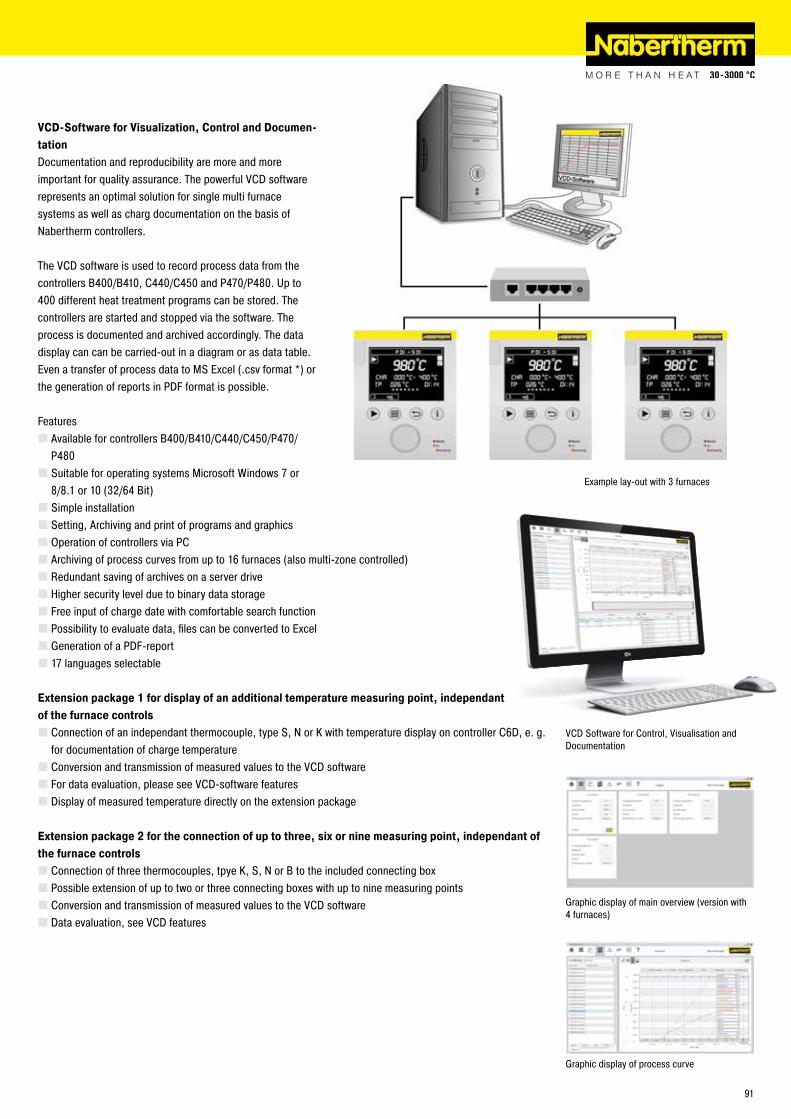
VCD Software for Control, Visualisation and Documentation
Example lay-out with 3 furnaces
Graphic display of main overview (version with 4 furnaces)
Graphic display of process curve
VCD-Software for Visualization, Control and Documen-tationDocumentation and reproducibility are more and more important for quality assurance. The powerful VCD software represents an optimal solution for single multi furnace systems as well as charg documentation on the basis of Nabertherm controllers.
The VCD software is used to record process data from the controllers B400/B410, C440/C450 and P470/P480. Up to 400 different heat treatment programs can be stored. The controllers are started and stopped via the software. The process is documented and archived accordingly. The data display can can be carried-out in a diagram or as data table. Even a transfer of process data to MS Excel (.csv format *) or the generation of reports in PDF format is possible.
Features � Available for controllers B400/B410/C440/C450/P470/P480 � Suitable for operating systems Microsoft Windows 7 or 8/8.1 or 10 (32/64 Bit) � Simple installation � Setting, Archiving and print of programs and graphics � Operation of controllers via PC � Archiving of process curves from up to 16 furnaces (also multi-zone controlled) � Redundant saving of archives on a server drive � Higher security level due to binary data storage � Free input of charge date with comfortable search function � Possibility to evaluate data, files can be converted to Excel � Generation of a PDF-report � 17 languages selectable
Extension package 1 for display of an additional temperature measuring point, independant of the furnace controls
� Connection of an independant thermocouple, type S, N or K with temperature display on controller C6D, e. g. for documentation of charge temperature � Conversion and transmission of measured values to the VCD software � For data evaluation, please see VCD-software features � Display of measured temperature directly on the extension package
Extension package 2 for the connection of up to three, six or nine measuring point, independant of the furnace controls
� Connection of three thermocouples, tpye K, S, N or B to the included connecting box � Possible extension of up to two or three connecting boxes with up to nine measuring points � Conversion and transmission of measured values to the VCD software � Data evaluation, see VCD features
91

Reg.
-Nr.
C 4.
2/09
.17
(Eng
lisch
), in
form
atio
n he
rein
is s
ubje
ct to
cha
nge
with
out n
otic
e. N
aber
ther
m a
ssum
es n
o lia
bilit
y fo
r any
erro
rs th
at m
ay a
ppea
r in
this
doc
umen
t.
www.nabertherm.com
Please visit our website www.nabertherm.com and find out all you want to know about us - and especially about our products.
Besides news and our current calendar of trade fairs, there is also the opportunity to get in touch directly with your local sales office or nearest dealer worldwide.
Professional Solutions for: � Arts & Crafts � Glass � Advanced Materials � Laboratory � Dental � Thermal Process Technology for Metals, Plastics and Surface Finishing � Foundry
The whole World of Nabertherm: www.nabertherm.com
SwitzerlandNabertherm Schweiz AGAltgraben 31 Nord4624 Härkingen, [email protected]
SpainNabertherm Españac/Marti i Julià, 8 Bajos 7a
08940 Cornellà de Llobregat, [email protected]
USANabertherm Inc.54 Read‘s WayNew Castle, DE 19720, [email protected]
Headquarters:
Nabertherm GmbHBahnhofstr. 2028865 Lilienthal, [email protected]
Sales Organisation
ChinaNabertherm Ltd. (Shanghai)150 Lane, No. 158 Pingbei Road, Minhang District201109 Shanghai, [email protected]
FranceNabertherm SARL20, Rue du Cap Vert21800 Quetigny, [email protected]
ItalyNabertherm ItaliaVia Trento N° 1750139 Florence, [email protected]
Great BritainNabertherm Ltd., United [email protected]
All other Countries: Followhttp://www.nabertherm.com/contacts