thermal, squeezing and compressibility effects in ...oaji.net/articles/2015/664-1423220561.pdf ·...
TRANSCRIPT
244
Vol. 36, No. 3 (2014) 244-258
Tribology in Industry
www.tribology.fink.rs
Thermal, Squeezing and Compressibility Effects in
Lubrication of Asymmetric Rollers
D. Prasad a, S.V. Subrahmanyam
b, S.S. Panda c
a Dr. S.R.K. Govt. Arts College, Yanam, India, b K.L. University, Guntur, India, c Regency Institute of Technology, Yanam, India.
Keywords:
Hydrodynamic lubrication
Non-Newtonian
Power law
Thermal effects
Squeezing
Compressibility
Consistency
A B S T R A C T
Hydrodynamically heavily loaded rigid cylindrical rollers, lubricated
by a thin compressible fluid film, are investigated for normal
squeezing motion and cavitations. The lubricant is assumed to follow
the non-Newtonian power-law fluid model where consistency and
density of the lubricant vary with one dimensional pressure and
temperature. The modified Reynolds pressure equation and thermal
energy equation are derived and solved simultaneously by R-K
Fehlberg method. Secant method is also applied in order to enforce
the boundary condition at the outlet. It is observed that temperature
has significant effects on consistency and density both. It is also to be
noted that compressibility effect is even more significant when
squeezing is taken into account.
© 2014 Published by Faculty of Engineering
Corresponding author:
S.V. Subrahmanyam,
K.L. University, Guntur-522502, Andhra
Pradesh, India
E-mail: [email protected]
1. INTRODUCTION
A contact between two surfaces is of great
importance in technology. At the interface of
two materials, when they brought together,
separated or moved with respect to one another,
contact information, friction, wear and
lubrication are the processes that occur [1].
Further, the Squeeze films play an important
role in the analysis of the dynamic behavior of
bearings and, in general, many practical
engineering systems. In order to model such
system proper knowledge of the forces
generated by the squeeze film in between solid
boundaries is necessary [2]. This situation
occurs frequently in many machine components
such as gear teeth, cams, automotive engines,
aircraft engines, rolling elements, machine tools,
skeletal joints, the bearings in reciprocating
engines and many more [3]. In this regard,
Dowson et al. [4] initiated the comprehensive
study of squeezing motion of Newtonian
lubrication of cylindrical rollers and obtained
the solution for a wide range of parameters.
Sinha et al. [5] examined this problem with
squeezing motion for non-Newtonian power law
lubricant. Prasad et al [6] extended the same
result with cavitation while adding thermal
effect where the consistency of the lubricant was
RE
SE
AR
CH
D. Prasad et al., Tribology in Industry Vol. 36, No. 3 (2014) 244-258
245
assumed to vary with pressure and the mean
temperature. Later, Rong-Tsonn and Hamrock [7]
made a comprehensive study of isothermal
Newtonian lubrication of both rigid and EHD line
contacts with compressibility and squeezing.
Usha and Rukmani Sridharan [2] investigated the
laminar squeeze flow of an incompressible
Newtonian fluid between non-rotating annular
surfaces including all inertial terms in the
governing equations of motion and a solution has
been obtained in terms of a single non-
dimensional squeeze Reynolds number S, for
small values of S. J-R Lin et al. [8] derived a
general dynamic Reynolds equation of sliding
squeezing surfaces with non-Newtonian fluids for
the assessment of dynamic characteristics of a
lubricating system and the transient squeezing
action effect is taken into account while
considering the effect of couple stresses resulting
from the lubricant blended with various
additives. Jaffar [3] studied a line contact problem
with squeezing effect, and various results were
reported for a wide range of layer thickness, the
layer compressibility and the central squeeze film
velocity. Bujurke et al. [9] observed the effects of
surface roughness on the characteristics of
squeeze film lubrication between curved annular
plates, and it was found that the effect of radial
(circumferential) roughness pattern is to shift the
point of maximum pressure towards the inlet
(outlet) edge. Further, it was observed that the
mean load carrying capacity was found to
increase (decrease) for the circumferential
(radial) roughness pattern compared with the
corresponding smooth case for both concave and
convex pad geometries. Naduvinamani et al [10]
made some investigations to study the combined
effects of unidirectional surface roughness and
magnetic effect on the performance
characteristics of porous squeeze film lubrication
between two rectangular plates and it was
observed that a roughness effect enhances
pressure, load carrying capacity and squeeze film
time. Recently, Li-Ming Chu et al [11] developed a
numerical method for general applications with
effects of surface force to investigate the pure
squeezing action within an isothermal thin film
EHL spherical conjunction under constant load
condition. Later, Jaw-Ren Lin [12] presented a
theoretical study of the non-Newtonian effects on
the squeeze film characteristics between parallel
annular disks on the basis of Rabinowitsch fluid
model. A closed form solution was derived using
a small perturbation method.
One of the other realistic conditions, which play
an important role in lubrication theory, is
compressibility effect. In fact, the
compressibility of liquid fluids under typical
engineering conditions is not normally an issue,
and most fluid mechanics analyses can be
performed assuming liquid incompressibility.
However, in concentrated lubricated contacts,
such as those formed in rolling element
bearings, gears, cams, and constant velocity
joints, etc., it is not uncommon for the lubricants
to be subjected to pressure variations within the
contact regions of around 109 pa and higher.
Under these conditions significant reductions in
fluid volume can be experienced [13].
Generally it may be difficult to consider liquids
as compressible media, but in high loaded EHL
contacts, the compressibility variation of the
lubricant is certainly not negligible. At high
loads, the compression of the lubricant has a
significant influence on the film thickness
variation inside the contact. A number of
different density models have been used in EHL
calculations through the year [14]. Prasad et al
[15] considered a problem of heavily loaded
rigid cylindrical rollers, lubricated by a thin
compressible power-law fluid assuming the
consistency and density of the lubricant vary
with temperature and pressure. As a result, it
was observed that for low values of power-law
index n there was no significant effect to
pressure and temperature on the consistency.
Even the compressibility effects are not very
significant for those low values. Hsiao-Ming Chu
et al [16] derived a one dimensional modified
Reynolds equation with power-law fluid from
the viscous adsorption theory for thin film EHL
including pressure- viscosity, pressure- density
characteristics of the lubricant and the visco-
elastic deformation of the rollers. Finally, the
film shape and the pressure distribution under
pure rolling conditions are numerically
calculated and discussed for various operating
conditions. Moraru and Keith [17] presented a
Lobatto point quadrature algorithm which is
applicable for TEHL problem where both density
and viscosity of the lubricant are taken to be
temperature and pressure dependent, and the
transverse velocity term in the energy equation
is obtained from the continuity equation. Use of
the Lobatto point calculation method has
resulted in accuracy without the use of a larger
number of grid points. Mircea D. Pascovici et al.

D. Prasad et al., Tribology in Industry Vol. 36, No. 3 (2014) 244-258
246
[18] proposed a model for the squeeze process
under impact for highly compressible porous
layers imbibed with fluids. It was assumed that
the normal forces generated by the elastic
compression of the fibers comprising the solid
face are negligible compared to the pressure
forces generated in the imbibed fluid, within the
porous layer. It was demonstrated for the
rectangular plates that the square plates could
minimize the maximum squeeze induced load.
Stolarski [19] verified the transient film
pressure of a squeeze film gas bearing
experimentally with comparison to numerical
results obtained from the Reynolds equation.
These two results were in good agreement with
CFD result for small vibrating amplitudes.
Bayada and Chupin [20] had shown how
vaporous cavitation in lubricant films can be
modeled in a physically justified manner
through the constitutive (compressibility)
relation of the fluid. It is found that how the
widely used Jakobsson–Floberg–Olsson (JFO) /
Elrod–Adams (EA) mass flow conservation
model can be compared with this new model.
Moreover, the new model can incorporate the
variation of the viscosity in the cavitation region
and allows the pressure to fall below a cavitation
pressure and numerical computations show that
discrepancy with JFO/EA is mostly associated
with light loading condition, starved situation or
viscosity effects. Habchi and Bair [21]
investigated the effects of lubricant
compressibility on the film-forming
performance of thermal elastohydrodynamic
lubricated (EHL) circular contacts. Numerical
film thickness predictions using the classical
Dowson and Higginson relationship are
compared to those that would be obtained using
a more realistic compressibility model. As a
result it is highlighted that highlights the
importance of using realistic transport
properties modeling based on thermodynamic
scaling for an accurate numerical prediction of
the performance of EHL contacts. Nadim A. Diab
and Issam Lakkis [22] investigated the effect of
various assumptions proposed by the classical
Reynolds lubrication equation. In particular, a
microplate oscillating at high frequencies
(beyond cutoff) and high velocities leading to
appreciable displacement within the film gap is
studied. Andreas Almqvist et al. [23] proposed a
theory based on clear physical arguments
related to conservation of mass flow and
considers both incompressible and compressible
fluids. The result of the mathematical modeling is
a system of equations with two unknowns, which
are related to the hydrodynamic pressure and the
degree of saturation of the fluid. The model and
the associated numerical solution method have
significant advantages over today’s most
frequently used cavitation algorithms, which are
based on Elrod–Adams pioneering work.
In addition, it is well known that the pressure, the
temperature and the film shape definitely play an
important role in the failure of heavily loaded non-
conformal contacts. In fact, the effect of heat
generated due to the shearing of the high pressure
lubricant is no longer negligible under sliding
conditions, as the heat changes the characteristics
of the oil flow because of a decrease in viscosity.
Therefore, thermal effect on the film thickness and
traction is significant in EHL contacts [24]. Further,
temperature rise in lubricant film occurs due to
rapid shear of lubricant layers. The hydrodynamic
action is affected due to the thermal effects [25].
Non-Newtonian behavior of the lubricants has
also been addressed severely. Because the
lubricants used in every day machines are seldom
single component liquids. In fact some base oil is
mixed with them. The base oils are often blends
of different molecular weight “cuts” to arrive at a
special ambient pressure viscosity. Also, viscosity
modifying polymer additives are often blended
with the base oil. In particular, the lubricants
used in automobiles are usually mixtures. The
non-Newtonian behavior of solutions of high-
molecular-weight polymers in low-molecular-
weight solvents, in shear flow and in extensional
flow, has been subject of much attention in
rheology [26,27]. The temperature rise for a non-
Newtonian lubricant can be better estimated
using power law lubricant [25].
The very purpose of lubrication is to separate
surfaces to relative motion in order to reduce
friction and wear. The separation and load
carrying capacity are achieved by generating a
pressure in the fluid film between the surfaces.
The most significant pressure build-up in
hydrodynamic lubrication is achieved when a
converging gap is allowed to form the surfaces. In
order to improve performance and efficiency, and
to reduce wear and risk of failure in
hydrodynamic lubrication, it is important to
study various effects that can contribute to the
pressure build-up [28].
D. Prasad et al., Tribology in Industry Vol. 36, No. 3 (2014) 244-258
247
Hence, in order to incorporate those various
effects of surface forces on squeeze thin film non-
Newtonian lubrication of rolling/sliding line
contact problem including compressibility and
cavitations, the modified Reynolds equation, the
energy equation and the lubricant rheology
equation are solved simultaneously. Also for semi
analytical solution, the surfaces are assumed to
be smooth and rigid. The consistency and the
density of the lubricant are assumed to vary with
pressure and temperature. An efficient method of
numerical solution with good accuracy is
employed to solve the above equations.
2. THEORETICAL MODEL
2.1 Momentum and Continuity Equations
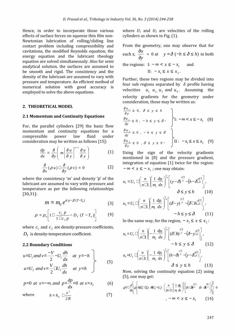
For, the parallel cylinders [29] the basic flow
momentum and continuity equations for a
compressible power law fluid under
consideration may be written as follows [15]:
∂∂
∂∂
∂∂=
−
y
u
y
um
ydx
dpn 1
(1)
0)()( =∂∂+
∂∂
vy
ux
ρρ (2)
where the consistency ‘m’ and density ‘ρ’ of the
lubricant are assumed to vary with pressure and
temperature as per the following relationships
[30,31]:
)(0
0TTpemm −−= βα (3)
−−
++= )(
11 0
2
10 TTD
pc
pcTρρ (4)
where 1c and 2c are density-pressure coefficients,
TD is density-temperature coefficient.
2.2 Boundary Conditions
hyatdx
dhU
VvandUu
hyatdx
dhU
VvandUu
=+==
−=−−==
22
11
2
2 (5)
20,0 xxatdx
dppandxatp ===∞−== (6)
where R
xhh
2
2
0 += (7)
where U1 and U2 are velocities of the rolling
cylinders as shown in Fig. (1).
From the geometry, one may observe that for
each x, y
u
∂∂
= 0 at )( hhy ≤≤−= δδ in both
the regions: I: 1xx −≤<∞− and
II: 21 xxx ≤≤− .
Further, these two regions may be divided into
four sub regions separated by � profile having
velocities 43,2,1 uanduuu . Assuming the
velocity gradients for the geometry under
consideration, those may be written as:
hyy
u≤≤≥
∂∂ δ,01
δ≤≤−≤∂
yhdy
u,02 , I: 1xx −≤<∞− (8)
δ≤≤−≥∂
yhdy
u,03
hyy
u≤≤≤
∂∂ δ,04 , II : 21 xxx ≤≤− (9)
Using the sign of the velocity gradients
mentioned in (8) and the pressure gradient,
integration of equation (1) twice for the region:
1xx −≤<∞− ; one may obtain:
( ) ,)(1
1
111
1
121
−−−
++=
++
n
nn
nn
hydx
dp
mn
nUu δδ
hy ≤≤δ (10)
( )
+−−
++=
++
n
nn
nn
hydx
dp
mn
nUu
111
1
112 )(
1
1δδ ,
δ≤≤− yh (11)
In the same way, for the region, 21 xxx ≤≤− :
( ) ,)(1
1
111
2
213
−−+
−
++=
++
n
nn
nn
yhdx
dp
mn
nUu δδ
δ≤≤− yh (12)
( ) ,)(1
1
111
2
224
−−−
−
++=
++
n
nn
nn
yhdx
dp
mn
nUu δδ
hy ≤≤δ (13)
Now, solving the continuity equation (2) using
(5), one may get:
12 1 2 1
11 1 1 2 1 2
1
1( ) ( ) ( ) ( ) 0
2 1
n nnn n
dpd nV hU U U U h h
dx n m dxρ ρ δ δ δ
+ + + + + − − + + − = +
, 1xx −≤<∞− (14)
D. Prasad et al., Tribology in Industry Vol. 36, No. 3 (2014) 244-258
248
0)()(1
12)()(
12121
2
2212122 =
−++
−
++−+++
++n
n
n
nn
hhdx
dp
mn
nUUUUh
dx
dV δδδρρ
, 21 xxx ≤≤− (15)
Let
−++
+−−++=−
++n
n
n
nn
hhdx
dp
mn
nUUUUhr
12121
1
1212111 )()(
1
12)()( δδδρ
(16)
and
−++
−
++−++=−
++n
n
n
nn
hhdx
dp
mn
nUUUUhr
12121
2
2212122 )()(
1
12)()( δδδρ
(17)
so that the equations (14) and (15) reduce to:
Vdx
dr1
1 ρ= (18)
Vdx
dr2
2 ρ= (19)
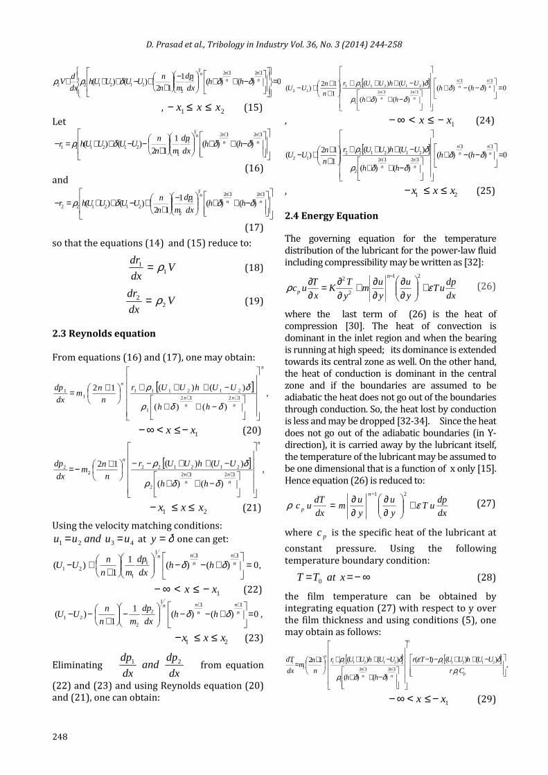
2.3 Reynolds equation
From equations (16) and (17), one may obtain:
[ ],
)()(
)()(121212
1
2121111
1
n
n
n
n
n
n
hh
UUhUUr
n
nm
dx
dp
−++
−+++
+=++
δδρ
δρ
1xx −≤<∞− (20)
[ ],
)()(
)()(121212
2
2121222
2
n
n
n
n
n
n
hh
UUhUUr
n
nm
dx
dp
−++
−++−−
+−=++
δδρ
δρ
21 xxx ≤≤− (21)
Using the velocity matching conditions:
4321 uuanduu == at δ=y one can get:
,0)()(1
1)(
111
1
121 =
+−−
++−
++n
n
n
nn
hhdx
dp
mn
nUU δδ
1xx −≤<∞− (22)
,0)()(1
1)(
111
2
221 =
+−−
−
+−−
++n
n
n
nn
hhdx
dp
mn
nUU δδ
21 xxx ≤≤− (23)
Eliminating dx
dpand
dx
dp 21 from equation
(22) and (23) and using Reynolds equation (20)
and (21), one can obtain:
[ ]0)()(
)()(
)()(
1
12)(
11
1212
1
21211112 =
−−+
−++
−+++
+++−
++
++n
n
n
n
n
n
n
nhh
hh
UUhUUr
n
nUU δδ
δδρ
δρ
, 1xx −≤<∞− (24)
[ ]0)()(
)()(
)()(
1
12)(
11
1212
2
21212212 =
−−+
−++
−+++
+++−
++
++n
n
n
n
n
n
n
nhh
hh
UUhUUr
n
nUU δδ
δδρ
δρ
, 21 xxx ≤≤− (25)
2.4 Energy Equation
The governing equation for the temperature
distribution of the lubricant for the power-law fluid
including compressibility may be written as [32]:
dx
dpuT
y
u
y
um
y
TK
x
Tuc
n
p ερ +
∂∂
∂∂+
∂∂=
∂∂
− 21
2
2
(26)
where the last term of (26) is the heat of
compression [30]. The heat of convection is
dominant in the inlet region and when the bearing
is running at high speed; its dominance is extended
towards its central zone as well. On the other hand,
the heat of conduction is dominant in the central
zone and if the boundaries are assumed to be
adiabatic the heat does not go out of the boundaries
through conduction. So, the heat lost by conduction
is less and may be dropped [32-34]. Since the heat
does not go out of the adiabatic boundaries (in Y-
direction), it is carried away by the lubricant itself,
the temperature of the lubricant may be assumed to
be one dimensional that is a function of x only [15].
Hence equation (26) is reduced to:
dx
dpuT
y
u
y
um
dx
dTuc
n
p ερ +
∂∂
∂∂=
− 21
(27)
where pc is the specific heat of the lubricant at
constant pressure. Using the following
temperature boundary condition:
∞−== xatTT 0 (28)
the film temperature can be obtained by
integrating equation (27) with respect to y over
the film thickness and using conditions (5), one
may obtain as follows:
[ ] [ ],
)()()1(
)()(
)()(12
1
21211
1212
1
2121111
1
−++−−
−++
−+++
+=
++p
n
n
n
n
n
n
Cr
UUhUUTr
hh
UUhUUr
n
nm
dx
dT
ρδρε
δδρ
δρ
1xx −≤<∞− (29)
D. Prasad et al., Tribology in Industry Vol. 36, No. 3 (2014) 244-258
249
[ ] [ ],
)()()1(
)()(
)()(12
2
21212
1212
2
2121222
2
−++−−
−++
−++−−
+−=
++p
n
n
n
n
n
n
Cs
UUhUUTs
hh
UUhUUr
n
nm
dx
dT
ρδρε
δδρ
δρ
21 xxx ≤≤− (30)
Now, using the following dimensionless scheme:
.,,,/,/,2
,/,/,/,,1
,212
2
1,,2,
2
0100
01
01202
0011
0
etchU
rr
h
R
U
VV
hhhUUUhTTxh
h
R
h
U
n
ncpcpcmcm
Rh
xx
mm
nn
nn
ρβεερρρ
δδβ
====
====+=
+====
(31)
The above equations (18), (19), (20), (21), (24),
(28) and (29) can be written as
Vxd
rd1ρ= (32)
Vxd
sd2ρ= (33)
nfmxd
pd)(1
1 = (34)
ngmxd
pd)(2
2 −−= (35)
0)()()(1
12)1(
11
=
−−+
+++−
++
fhhn
nU n
n
n
n
δδ (36)
0)()()(1
12)1(
11
=
−−+
+++−
++
ghhn
nU n
n
n
n
δδ (37)
111 )( ψγ nfm
xd
Td= (38)
222 )( ψγ ngm
xd
Td−−= (39)
Where
)(1
1 0TTDpA
pT +−
++=ρ (40)
)(01
01 TTpBemm +−= , etc. (41)
Where 12 / ccA= , and 1/ cB α=
[ ]
−++
−+++=
++n
n
n
n
hh
UhUrf
1212
1
11
)()(
)1()1(
δδρ
δρ (42)
[ ]
−++
−+++=++
n
n
n
n
hh
UhUrg
1212
2
22
)()(
)1()1(
δδρ
δρ (43)
=
pcc10ρβγ (44)
[ ]11
1111
)1()1()1(
ρδρεψ
r
UhUTr −++−−= (45)
[ ]22
2222
)1()1()1(
ρδρεψ
r
UhUTr −++−−= (46)
2.5 Load and Traction
The load components W in the y-direction is
calculated as:
W= ∫∞−
2x
dxp (47)
The dimensionless load
02Rh
wW
α= is given by:
∫ ∫∞− ∞−
−==2 2x x
xdxd
pdxxdpW (48)
The surface traction force is obtained from the
integration of shear stress � over the entire
fluid flow regions; and one may get:
∫∞−
−=− −=2x
hyFh dxT τ (49)
∫∞−
=+ −=2x
hyFh dxT τ (50)
Dimensionless tractions are:
∫∞−
−=− −=
=
2
0
0
x
hy
FFh xd
h
TT τα (51)
∫∞−
=+ −=2x
hyFh xdT τ (52)
3. RESULTS AND DISCUSSION
A typical semi analytical solution of the modified
Reynolds equations (34), (35) and the energy
equations (38), (39) have been obtained for
symmetrical and asymmetrical, viscous
compressible flow of power law fluids throughout
the gap between two cylinders, Fig. 1. The results
of the investigation are assessed in terms of
parameters n, U (= 12 /UU , 12 UU > ) and V .
D. Prasad et al., Tribology in Industry Vol. 36, No. 3 (2014) 244-258
250
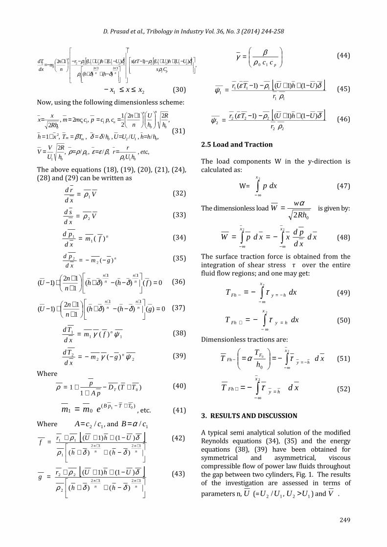
Fig. 1. Lubrication of Asymmetric rollers.
The values of the flow index n is considered to
be greater than unity for dilatants fluid, equal to
unity Newtonian and less than unity Pseudo
plastic. The sliding parameter U is chosen to lie
between 1.0 and 1.4. The parameter U arises
due to the consideration of anti-symmetric
conditions and is important because the
presence of sliding (U >1) is likely to produce
greater pressure and temperature as compared
to that of pure rolling (U =1). The significance
of U along with n has been demonstrated
through table and graphs for 0≠β . For the
numerical calculation, the following
representative values have been used:
scmU /4002 = , cmh 40 10−= ,
219106.1 cmdyne−−×=α , R=3cm, γ = 5, 19
1 106.0 −−×= pac , 19
2 107.1 −−×= pac , 131065.0 −−×= KDT .
It may be noted that the flow configuration
considered herein includes several known
situations as limiting cases: for instance when
21 UU = , and m is constant, it reduces to the case
examined by Sinha and Singh [35]; for the case
β=0, this is the case considered by Sinha and Raj
[36]. Further, when 21 UU = , and 0≠β , the
present analysis is equivalent to that of Prasad
et al. [15].
3.1 Numerical Solutions
The Reynolds and the energy equations are coupled
through m , and contain two unknowns δ (the
locus of point at which 0=∂∂
y
u) and the initial value
of r . These unknowns are also present in equation
(36). As there is no symmetry (U ≠1), it is
necessary to solve (36) for δ . The actual process
followed for numerical computation of ε -δ is
briefly described below in the flow chart.
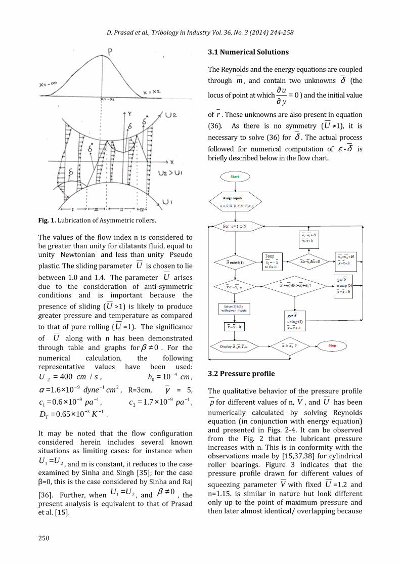
3.2 Pressure profile
The qualitative behavior of the pressure profile
p for different values of n, V , and U has been
numerically calculated by solving Reynolds
equation (in conjunction with energy equation)
and presented in Figs. 2-4. It can be observed
from the Fig. 2 that the lubricant pressure
increases with n. This is in conformity with the
observations made by [15,37,38] for cylindrical
roller bearings. Figure 3 indicates that the
pressure profile drawn for different values of
squeezing parameter V with fixed U =1.2 and
n=1.15. is similar in nature but look different
only up to the point of maximum pressure and
then later almost identical/ overlapping because
D. Prasad et al., Tribology in Industry Vol. 36, No. 3 (2014) 244-258
251
there is sharp decrease in compressible pressure
there near the outlet [39]. This shows that the
squeezing and the compressible effects are not
very significant near the outlet in case of rolling
and sliding condition. Further, the pressure for
V =0 is lower when compared to that of V =0.2,
and higher than in comparison to V =-0.2.
Fig. 2. Pressure profile p versus x .
Fig. 3. Pressure profile p versus x .
This result is almost similar to that of [3] for
compressible – squeezing with line contact.
However, the above trend does not match with
symmetric and incompressible result [6].
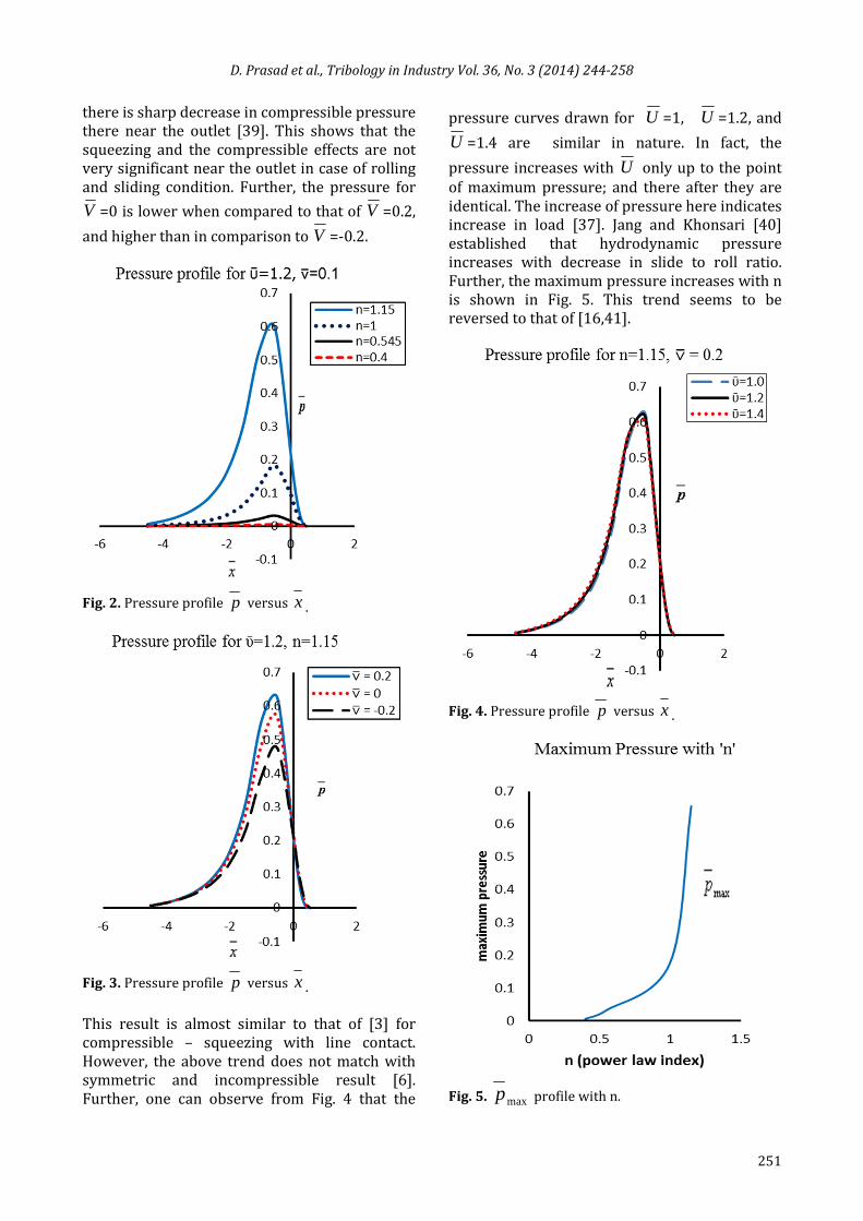
Further, one can observe from Fig. 4 that the
pressure curves drawn for U =1, U =1.2, and
U =1.4 are similar in nature. In fact, the
pressure increases with U only up to the point
of maximum pressure; and there after they are
identical. The increase of pressure here indicates
increase in load [37]. Jang and Khonsari [40]
established that hydrodynamic pressure
increases with decrease in slide to roll ratio.
Further, the maximum pressure increases with n
is shown in Fig. 5. This trend seems to be
reversed to that of [16,41].
Fig. 4. Pressure profile p versus x .
Fig. 5. maxp profile with n.
D. Prasad et al., Tribology in Industry Vol. 36, No. 3 (2014) 244-258
252
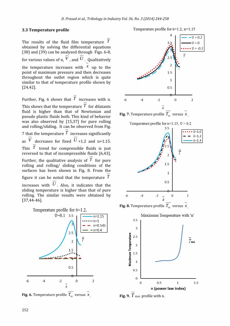
3.3 Temperature profile
The results of the fluid film temperature T
obtained by solving the differential equations
(38) and (39) can be analyzed through Figs. 6-8,
for various values of n, V , and U . Qualitatively
the temperature increases with x up to the
point of maximum pressure and then decreases
throughout the outlet region which is quite
similar to that of temperature profile shown by
[24,42].
Further, Fig. 6 shows that T increases with n.
This shows that the temperature T for dilatants
fluid is higher than that of Newtonian and
pseudo plastic fluids both. This kind of behavior
was also observed by [15,37] for pure rolling
and rolling/sliding. It can be observed from Fig.
7 that the temperature T increases significantly
as V decreases for fixed U =1.2 and n=1.15.
This T trend for compressible fluids is just
reversed to that of incompressible fluids [6,43].
Further, the qualitative analysis of T for pure
rolling and rolling/ sliding conditions of the
surfaces has been shown in Fig. 8. From the
figure it can be noted that the temperature T
increases with U . Also, it indicates that the
sliding temperature is higher than that of pure
rolling. The similar results were obtained by
[37,44-46].
Fig. 6. Temperature profile mT versus x .
Fig. 7. Temperature profile mT versus x .
Fig. 8. Temperature profile mT versus x .
Fig. 9. maxT profile with n.
D. Prasad et al., Tribology in Industry Vol. 36, No. 3 (2014) 244-258
253
The maximum lubricant temperature increases
with n is shown in Fig. 9, and is in conformity
with the previous findings of [37,39,41].
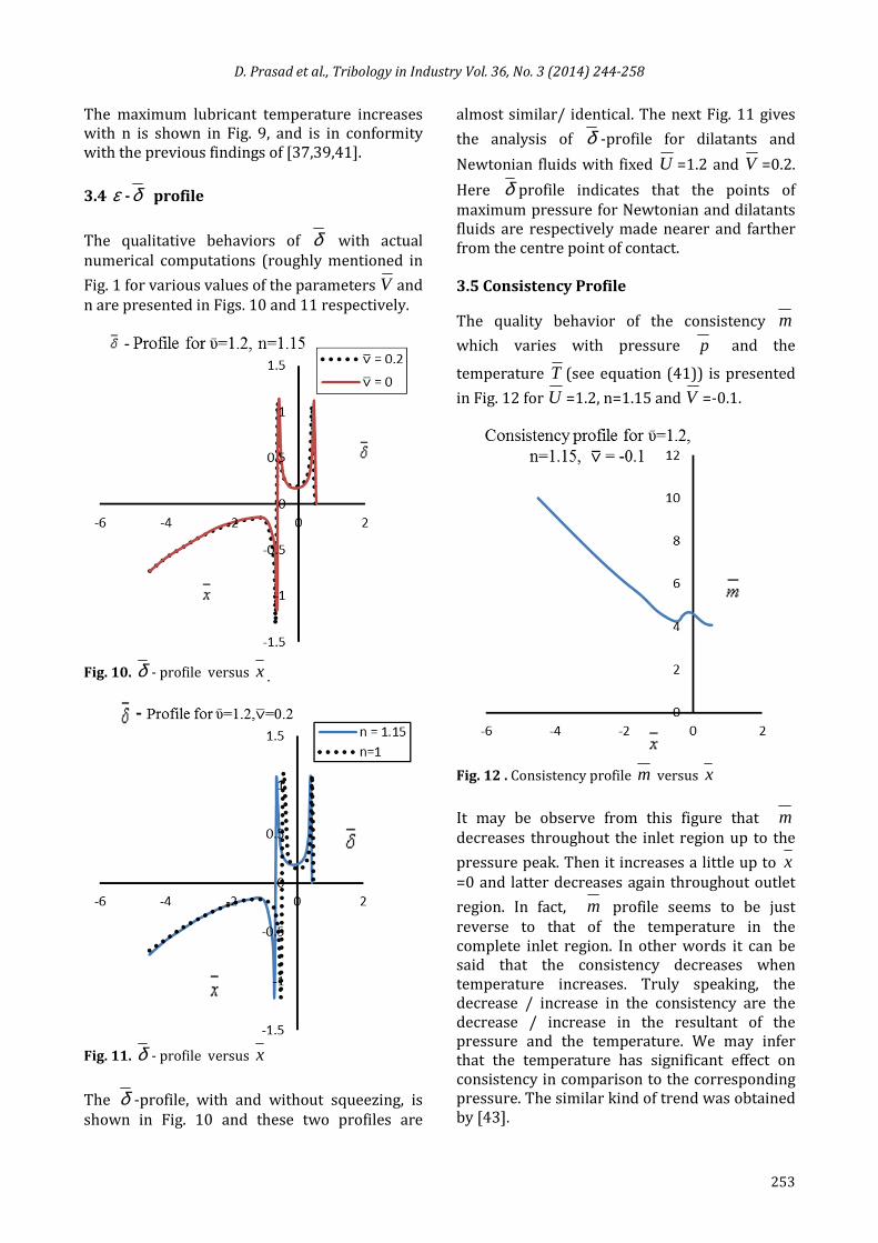
3.4 ε -δ profile
The qualitative behaviors of δ with actual
numerical computations (roughly mentioned in
Fig. 1 for various values of the parameters V and
n are presented in Figs. 10 and 11 respectively.
Fig. 10. δ - profile versus x .
Fig. 11. δ - profile versus x
The δ -profile, with and without squeezing, is
shown in Fig. 10 and these two profiles are
almost similar/ identical. The next Fig. 11 gives
the analysis of δ -profile for dilatants and
Newtonian fluids with fixed U =1.2 and V =0.2.
Here δ profile indicates that the points of
maximum pressure for Newtonian and dilatants
fluids are respectively made nearer and farther
from the centre point of contact.
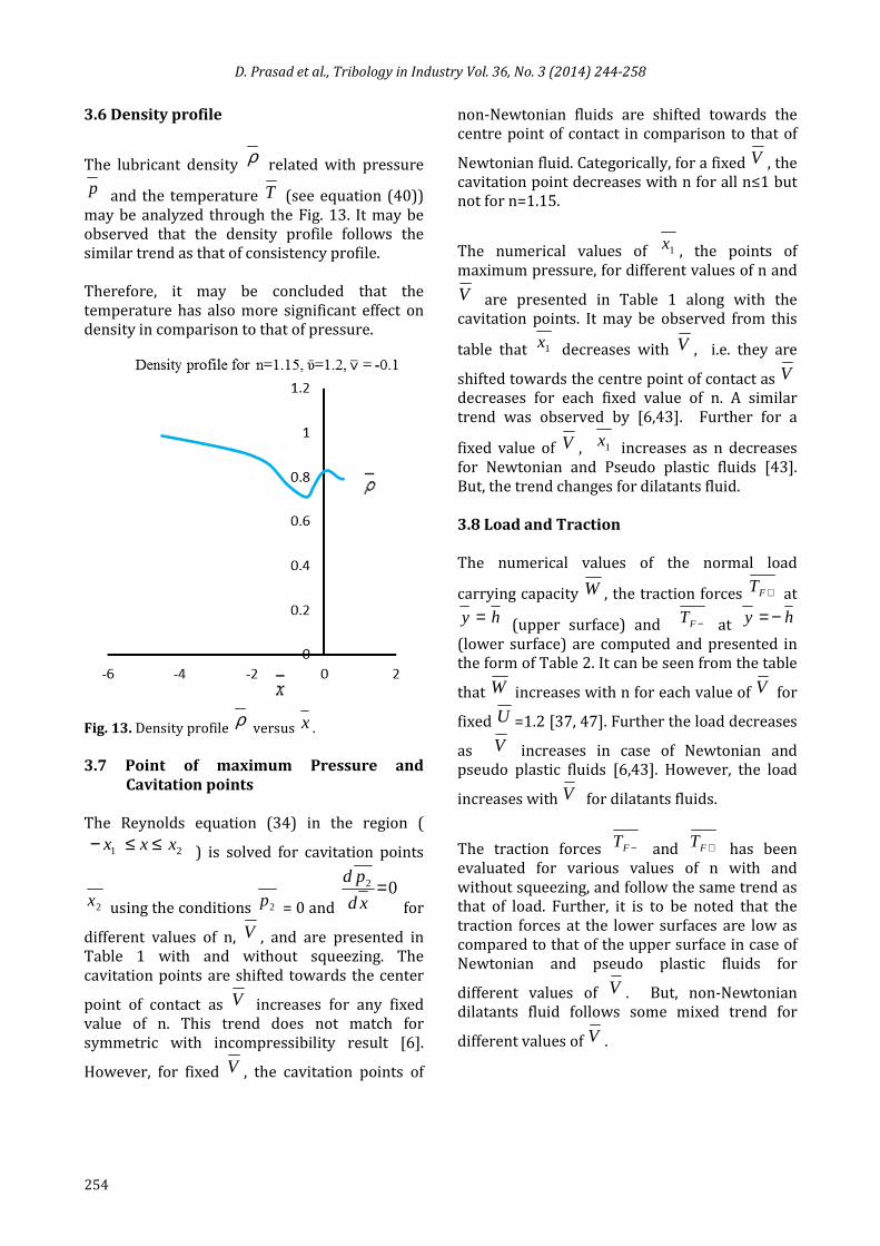
3.5 Consistency Profile
The quality behavior of the consistency m
which varies with pressure p and the
temperature T (see equation (41)) is presented
in Fig. 12 for U =1.2, n=1.15 and V =-0.1.
Fig. 12 . Consistency profile m versus x
It may be observe from this figure that m
decreases throughout the inlet region up to the
pressure peak. Then it increases a little up to x=0 and latter decreases again throughout outlet
region. In fact, m profile seems to be just
reverse to that of the temperature in the
complete inlet region. In other words it can be
said that the consistency decreases when
temperature increases. Truly speaking, the
decrease / increase in the consistency are the
decrease / increase in the resultant of the
pressure and the temperature. We may infer
that the temperature has significant effect on
consistency in comparison to the corresponding
pressure. The similar kind of trend was obtained
by [43].
D. Prasad et al., Tribology in Industry Vol. 36, No. 3 (2014) 244-258
254
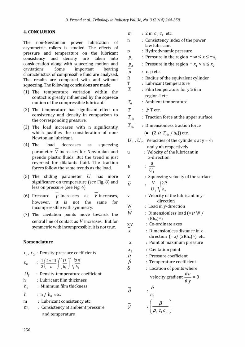
3.6 Density profile
The lubricant density ρ related with pressure
p and the temperature T (see equation (40))
may be analyzed through the Fig. 13. It may be
observed that the density profile follows the
similar trend as that of consistency profile.
Therefore, it may be concluded that the
temperature has also more significant effect on
density in comparison to that of pressure.
Fig. 13. Density profile ρ
versus x .
3.7 Point of maximum Pressure and
Cavitation points
The Reynolds equation (34) in the region (
21 xxx ≤≤− ) is solved for cavitation points
2x using the conditions 2p = 0 and
02 =xd
pd
for
different values of n, V , and are presented in
Table 1 with and without squeezing. The
cavitation points are shifted towards the center
point of contact as V increases for any fixed
value of n. This trend does not match for
symmetric with incompressibility result [6].
However, for fixed V , the cavitation points of
non-Newtonian fluids are shifted towards the
centre point of contact in comparison to that of
Newtonian fluid. Categorically, for a fixed V , the
cavitation point decreases with n for all n≤1 but
not for n=1.15.
The numerical values of 1x , the points of
maximum pressure, for different values of n and
V are presented in Table 1 along with the
cavitation points. It may be observed from this
table that 1x decreases with V , i.e. they are
shifted towards the centre point of contact as Vdecreases for each fixed value of n. A similar
trend was observed by [6,43]. Further for a
fixed value of V , 1x increases as n decreases
for Newtonian and Pseudo plastic fluids [43].
But, the trend changes for dilatants fluid.
3.8 Load and Traction
The numerical values of the normal load
carrying capacity W , the traction forces +FT at
hy = (upper surface) and −FT at hy −=
(lower surface) are computed and presented in
the form of Table 2. It can be seen from the table
that W increases with n for each value of V for
fixed U =1.2 [37, 47]. Further the load decreases
as V increases in case of Newtonian and
pseudo plastic fluids [6,43]. However, the load
increases with V for dilatants fluids.
The traction forces −FT and +FT has been
evaluated for various values of n with and
without squeezing, and follow the same trend as
that of load. Further, it is to be noted that the
traction forces at the lower surfaces are low as
compared to that of the upper surface in case of
Newtonian and pseudo plastic fluids for
different values of V . But, non-Newtonian
dilatants fluid follows some mixed trend for
different values of V .

D. Prasad et al., Tribology in Industry Vol. 36, No. 3 (2014) 244-258
255
Table 1. Points of maximum pressure and cavitations.
n/m0 Squeeze )(V → 0.2 0.1 0 -0.1 -0.2
1.15/0.56
r -3.217899 -2.713841 -2.213761 -1.719251 -1.231699
1x 0.664004 0.645405 0.627405 0.606005 0.583005
2x 0.464288 0.488188 0.512863 0.537587 0.561862
1.0/0.75
r -3.728461 -3.235166 -2.739885 -2.242121 -1.743979
1x 0.470407 0.454807 0.440407 0.426407 0.413008
2x 0.505988 0.536862 0.568187 0.599986 0.632186
0.545/86.0
r -3.698291 -3.214899 -2.730269 -2.244369 -1.757370
1x 0.503006 0.485807 0.469407 0.453007 0.437407
2x 0.469588 0.498988 0.528862 0.559287 0.590187
0.4/126.0
r -3.689511 -3.208103 -2.725302 -2.241417 -1.756477
1x 0.516006 0.498706 0.481807 0.465007 0.448807
2x 0.461863 0.490863 0.519588 0.549187 0.579587
Table 2. Load, Traction Forces, Maximum Pressure and Temperature.
n/m0 Squeeze )(V → 0.2 0.1 0 -0.1 -0.2
1.15/0.56
W 1.067529 1.028345 0.980613 0.917716 0.836443
+FT 3.658551 3.500792 3.307765 3.07431 2.784633
−FT 3.670508 3.504292 3.30484 3.064961 2.770892
maxp 0.654358 0.620095 0.581410 0.534853 0.479133
maxT 3.204486 3.259898 3.320452 3.734473 3.428965
1.0/0.75
W 0.265008 0.274883 0.274883 0.291903 0.297764
+FT 0.84411 0.866352 0.886035 0.902093 0.911975
−FT 0.839128 0.86094 0.880494 0.896071 0.905897
maxp 0.176292 0.183137 0.189353 0.194569 0.198188
maxT 1.318532 1.346509 1.377697 1.413827 1.455596
0.545/86.0
W 0.049622 0.051109 0.052587 0.054041 0.055429
+FT 0.166225 0.169777 0.172861 0.175865 0.178619
−FT 0.158302 0.169421 0.172454 0.175318 0.178007
maxp 0.03075 0.031717 0.032668 0.033594 0.034468
maxT 1.057986 1.062688 1.068191 1.074813 1.08309
0.4/126.0
W 0.009421 0.009675 0.009934 0.010195 0.010456
+FT 0.032163 0.0327 0.033233 0.03377 0.034296
−FT 0.032235 0.032742 0.033252 0.033762 0.034272
maxp 0.005705 0.005867 0.006029 0.006192 0.006354
maxT 1.011027 1.011909 1.012952 1.014228 1.01585
D. Prasad et al., Tribology in Industry Vol. 36, No. 3 (2014) 244-258
256
4. CONCLUSION
The non-Newtonian power lubrication of
asymmetric rollers is studied. The effects of
pressure and temperature on the lubricant
consistency and density are taken into
consideration along with squeezing motion and
cavitations. Some important bearing
characteristics of compressible fluid are analyzed.
The results are compared with and without
squeezing. The following conclusions are made:
(1) The temperature variation within the
contact is greatly influenced by the squeeze
motion of the compressible lubricants.
(2) The temperature has significant effect on
consistency and density in comparison to
the corresponding pressure.
(3) The load increases with n significantly
which justifies the consideration of non-
Newtonian lubricant.
(4) The load decreases as squeezing
parameter V increases for Newtonian and
pseudo plastic fluids. But the trend is just
reversed for dilatants fluid. The traction
forces follow the same trends as the load.
(5) The sliding parameter U has more
significance on temperature (see Fig. 8) and
less on pressure (see Fig. 4)
(6) Pressure p increases as V increases,
however, it is not the same for
incompressible with symmetry.
(7) The cavitation points move towards the
central line of contact as V increases. But for
symmetric with incompressible, it is not true.
Nomenclature
1c , 2c : Density-pressure coefficients
nc :
00
212
2
1
h
R
h
U
n
nnn
+
TD : Density-temperature coefficient
h : Lubricant film thickness
0h : Minimum film thickness
h : h / 0h etc.
m : Lubricant consistency etc.
0m : Consistency at ambient pressure
and temperature
m : 2 m nc 1c etc.
n : Consistency index of the power
law lubricant
p : Hydrodynamic pressure
1p : Pressure in the region 1xx −≤<∞−
2p : Pressure in the region 21 xxx ≤<−
p : 1c p etc.
R : Radius of the equivalent cylinder
T : Lubricant temperature
1T : Film temperature for y ≥ δ in
region-I etc.
0T : Ambient temperature
T : β T etc.
FhT : Traction force at the upper surface
FhT : Dimensionless traction force
(= - (2 α FhT / ho)) etc.
21 , UU : Velocities of the cylinders at y = -h
and y =h respectively
u : Velocity of the lubricant in
x-direction
u : 1U
u
V : Squeezing velocity of the surface
V :
01
2
h
R
U
V
v : Velocity of the lubricant in y-
direction
W : Load in y-direction
W : Dimensionless load (=α W /
(Rho)½)
x,y : Co-ordinate axes
x : Dimensionless distance in x-
direction (= x/ (2Rho)½) etc.
1x : Point of maximum pressure
2x : Cavitation point
α : Pressure coefficient
β : Temperature coefficient
δ : Location of points where
velocity gradient 0=∂∂
y
u
δ : 0h
δ
γ :
pcc10ρβ

D. Prasad et al., Tribology in Industry Vol. 36, No. 3 (2014) 244-258
257
REFERENCES
[1] J. Manojlović: Dynamics of SAMs in Boundary
Lubrication, Tribology in Industry, Vol. 35, No.
3, pp. 200-207, 2013.
[2] R. Usha, Rukmani Sridharan: An investigation of
a squeeze film between two plane annuli, Journal
of Tribology, Vol. 120, No. 3, pp. 610-615, 1988.
[3] M.J. Jaffar: Squeeze films between a rigid cylinder
and an elastic layer bonded to a rigid foundation,
Tribology International, Vol. 40, No. 3, pp. 567-
572, 2007.
[4] D. Dowson, P.H. Markho, D.A. Jones: The
lubrication of lightly loaded cylinders in
combined rolling, sliding and normal motion,
part-i, theory, ASME Journal of Lubrication
Technology, Vol. 98, No. 4, pp. 509-517, 1976.
[5] P. Sinha, J.B. Shukla, K.R. Prasad, C. Singh: Non-
Newtonian power-law fluid lubrication of lightly
loaded cylinders with normal and rolling motion,
Wear, Vol. 89, No. 3, pp. 313-322, 1983.
[6] D. Prasad, P. Singh, P. Sinha: Thermal and
squeezing effects in non-newtonian fluid film
lubrication of rollers, Wear, Vol. 119, No. 2, pp.
175-190, 1987.
[7] L. Rong-Tsong, B.J. Hamrock: Squeezing and
entraining motion in non-conformal line contacts:
part-I,Hydrodynamic lubrication, ASME, Journal of
Tribology, Vol. 111, No. 1, pp. 1-7, 1989.
[8] J-R Lin, R-F Lu, T-B Chang: Derivation of Dynamic
Couple-Stress Reynolds Equation of Sliding Squeezing
Surfaces and Numerical Solution of Plane Inclined
Slider Bearings, Tribology International, Vol. 36, No.
9, pp. 679-685, 2003.
[9] N.M. Bujurke, N.B. Naduvinamani, D.P. Basti:
Effect of surface roughness on the squeeze film
lubrication between curved annular plates,
Industrial Lubrication and Tribology, Vol. 59,
No. 4, pp. 178-185, 2007.
[10] N.B. Nadivinamani, Syeda Thasneem Fathima,
Salma Jamal: Effect of roughness on
hydrodynamic squeeze films between porous
rectangular plates, Tribology International, Vol.
43, pp. 2145-2151, 2010.
[11] Li-Ming Chu, Jin Yuan Lai, Chi-Hui Chien, Wang
Long Li: Effect of surface forces on pure squeeze
thin film EHL motion of circular contacts,
Tribology International, Vol. 43, No. 3, pp. 523-
531, 2010.
[12] Jaw-Ren Lin: Non-Newtonian squeeze film
characteristics between parallel annular disks:
rabinowitsch fluid model, Tribology
International, Vol. 52, pp. 190-194, 2012.
[13] S. Kondo, R.S. Sayles, M.J.S. Lowe: A combined
optical-ultrasonic method of establishing the
compressibility of high-pressure oil and grease
films entrapped in a ball on flat contact, Journal
of Tribology, Vol. 128, No. 1, pp. 155-167, 2006.
[14] Jonas Stahl, O. Jacobson: Compressibility of
lubricants at high pressure, Tribology
Transactions, Vol. 46, No. 4, pp. 592-599, 2003.
[15] D. Prasad, P. Singh, P. Sinha: Non-uniform
temperature in non-Newtonian compressible
fluid film lubrication of rollers, ASME Journal of
Tribology, Vol. 110, No. 4, pp. 653-658, 1988.
[16] Hsiao-Ming Chu, Wang-Long Li, Yuh-Ping Chang:
Thin film elastohydrodynamic lubrication – A
power law fluid model, Tribology International,
Vol. 39, No. 11, pp. 1474-1481, 2006.
[17] L. Moraru, T.G. Keith: Lobatto point quadrature
for thermal lubrication problems involving
compressible lubricants. EHL applications,
Journal of Tribology, Vol. 129, No. 1, pp. 194-
198, 2007.
[18] Mircea D. Pascovici, Traian Cicone, Victor Marin:
Squeeze process under impact in highly
compressible porous layers, imbibed with liquids,
Tribology International, Vol. 42, No. 10, pp.
1433-1438, 2009.
[19] T.A. Stolarski: Numerical modeling and
experimental verification of compressible
squeeze film pressure, Tribology International,
Vol. 43, No. 1-2, pp. 356-360, 2010.
[20] G. Bayada, L. Chupin: Compressible fluid model
for hydrodynamic lubrication cavitation, Journal
of Tribology, Vol. 135, No. 4, pp. 041702-1 to
041702-13, 2013.
[21] W. Habchi, S. Bair: Quantitative compressibility
effects in thermal elastohydrodynamic circular
contacts, Journal of Tribology, Vol. 135, No. 1,
pp. 011502-1 to 011502-10, 2013.
[22] Nadim A. Diab, Issam Lakkis: Modeling squeeze
films in the vicinity of high inertia oscillating
microstructures, Journal of Tribology, Vol. 136,
No. 2, pp. 021705-1 to 021705-8, 2014.
[23] Andreas Almqvist, John Fabricius, Roland
Larsson, Peter Wall: A new approach for
studying cavitation in lubrication, Journal of
Tribology, Vol. 136, No. 1, pp. 011706-1 to
011706-7, 2014.
[24] Li-Ming Chu, Hsiang-Chen Hsu, Jaw-Ren Lin,
Yuh-Ping Chang: Inverse approach for
calculating temperature in EHL of line contacts,
Tribology International, Vol. 42, No. 8, pp. 1154-
1162, 2009.
D. Prasad et al., Tribology in Industry Vol. 36, No. 3 (2014) 244-258
258
[25] P.C. Mishra: Analysis of a Rough Elliptic Bore
Journal Bearing using Expectancy Model of
Roughness Characterization, Tribology in
Industry, Vol. 36, No. 2, pp. 211-219, 2014.
[26] Yuchuan Liu, Jane Wang, Ivan Krupka, Martin
Hartl, Scott Bair: The shear thinning
elastohydrodynamic film thickness of a two
component mixture, Journal of Tribology, Vol.
130, No. 2, pp. 021502-1 to 021502-7, 2008.
[27] R.I. Tanner: Engineering Rheology, Oxford
University Press, 2nd Edn, PP. 129-133, Oxford,
2000.
[28] Fredrik Sahlin, Sergie B. Glavatskin, Torbjorn
Almqvist, Roland Larson: Two dimensional CFD
analysis of micro-patterned surfaces in
hydrodynamic lubrication, Journal of Tribology,
Vol. 127, No. 1, pp. 96-102, 2005.
[29] A.A. Minewitsch: Some Developments in
Triboanalysis of Coated Machine Components,
Tribology in Industry, Vol. 33, No. 4, pp. 153-
158, 2011.
[30] H.S. Cheng, B. Sternlicht: A numerical solution
for pressure, temperature and film thickness
between two infinitely long lubricate rolling and
sliding cylinders, under heavy loads, Journal of
Basic Engineering, Vol. 87, pp. 695, 1965.
[31] P. Yang, J. Wang, M. Kaneta: Thermal and non-
Newtonian numerical analyses for starved EHL
line contacts, Journal of Tribology, Vol. 128, No.
2, pp. 282-290, 2006.
[32] J.B. Shukla, M. Isa: Thermal effects in squeeze
films and externally pressurized bearing with
power-law lubricants, Wear, Vol. 51, No. 2, pp.
237-251, 1978.
[33] O. Pinkus, B. Sternlicht: Theory of hydrodynamic
lubrication, Mc Graw Hill Publication, New York,
pp. 286, 1961.
[34] Hashimoto and M. Mongkolwongrojn, C.
Prabkaew: Non-Newtoian turbulent lubrication
theory based on friction law of fluid,
Transactions of Japan Society of Mechanical
Engineers, Part C, Vol. 60, pp. 1006-1012, 1994.
[35] P. Sinha, C. Singh: Lubrication of cylinder on a
plane with a non-newtonian fluid considering
cavitation, ASME Journal Of Lubrication
Technology, Vol. 104, No. 2, pp. 168-172, 1982.
[36] P. Sinha, S.A. Raj: Exponential viscosity variation
in the non-newtonian lubrication of rollers
considering cavitations, Wear, Vol. 87, No. 1, pp.
29-38, 1983.
[37] D. Prasad, J.B. Shukla, P. Singh, P. Sinha, R.P.
Chhabra: Thermal effects in lubrication of
asymmetrical rollers, Tribology International,
Vol. 24, No. 4, pp. 239-246, 1991.
[38] S.H. Wang, D.Y. Hua, H.H. Zang: A full numerical
EHL solution for line contacts under pure rolling
condition with a non-Newtonian rheological
model, ASME, Journal of Tribology, Vol. 110, No.
4, pp. 583-586, 1988.
[39] P.K. Saini, P. Kumar, P. Tandon: Thermal
elastohydrodynamic lubrication characteristics
of couple stress fluids in rolling/sliding line
contacts, Journal of Engineering Tribology, Vol.
221, No. 2, pp. 141-153, 2007.
[40] J.Y. Jang, M.M. Khonsari: Elastohydrodynamic
line contact of compressible shear thinning fluids
with consideration of the surface roughness,
ASME, Journal of Tribology, Vol. 132, No. 3, pp.
034501-1 to 034501-6, 2010.
[41] Punit Kumar, S.C. Jain, S. Ray: Thermal EHL
lubrication of rolling/sliding line contacts using a
mixture of Newtonian and power law fluids,
2008, Journal of Engineering Tribology, Vol.
222, No. 1, pp. 35-49, 2008.
[42] A. Almqvist, J. Dasht: The homogenization process
of the Reynolds equation describing compressible
liquid flow, Tribology International, Vol. 39, No. 9,
pp. 994-1002, 2006.
[43] D. Prasad, P. Singh, Prawal Sinha: Thermal and
inertia effects in hydrodynamic lubrication of
rollers by a power law fluid considering
cavitations, Journal of Tribology, Vol. 115, No. 2,
pp. 319-326, 1993.
[44] M.K. Ghosh, B.J. Hamrock: Thermal EHD
lubrication of line contacts, ASLE, Vol. 28, pp.
159-171, 1985.
[45] F. Sadeghi, T.A. Dow, R.R. Johnson: Thermal
effects in rolling/sliding contacts: part-3,
Approximate method for prediction of mid-film
temperature and sliding traction, Journal of
Tribology, Vol. 109, No. 3, pp. 519-523, 1987.
[46] P.N. Bogdanovich, D.V. Tkachuk: Temperature
distribution over contact area and ‘Hot Spots’ in
rubbing solid contact, Tribology International,
Vol. 39, No. 11, pp. 1355-1360, 2006.
[47] D. Prasad, P. Singh, Prawal Sinha: Thermal and
inertia effects in rollers with power law lubricant
having temperature and pressure dependent
consistency, Indian Journal of Pure and Applied
Mathematics, Vol. 24, No. 4, pp. 305-320, 1992.