thermal storage for solar thermal power plants · · 2013-12-30optical concentrator direct solar...
TRANSCRIPT
Dr. Rocío BayónConcentrating solar systems, CIEMAT-PSAe-mail: [email protected]
International workshop
19-22 December 2013
Design of Sub-Systems for Concentrated Solar Power Technologies
Thermal storage for solar thermal power plants
Design of Sub-Systems for Concentrated Solar Power TechnologiesJodhpur, 19-22 Dec. 2013
Contents
1. Introduction• Advantages & disadvantages• Classification• Requirements
2. Sensible heat storage3. Latent heat storage4. Thermochemical storage5. Thermal storage challenges and research directions6. Examples of solar thermal power plants with
thermal storage in Spain
Design of Sub-Systems for Concentrated Solar Power TechnologiesJodhpur, 19-22 Dec. 2013
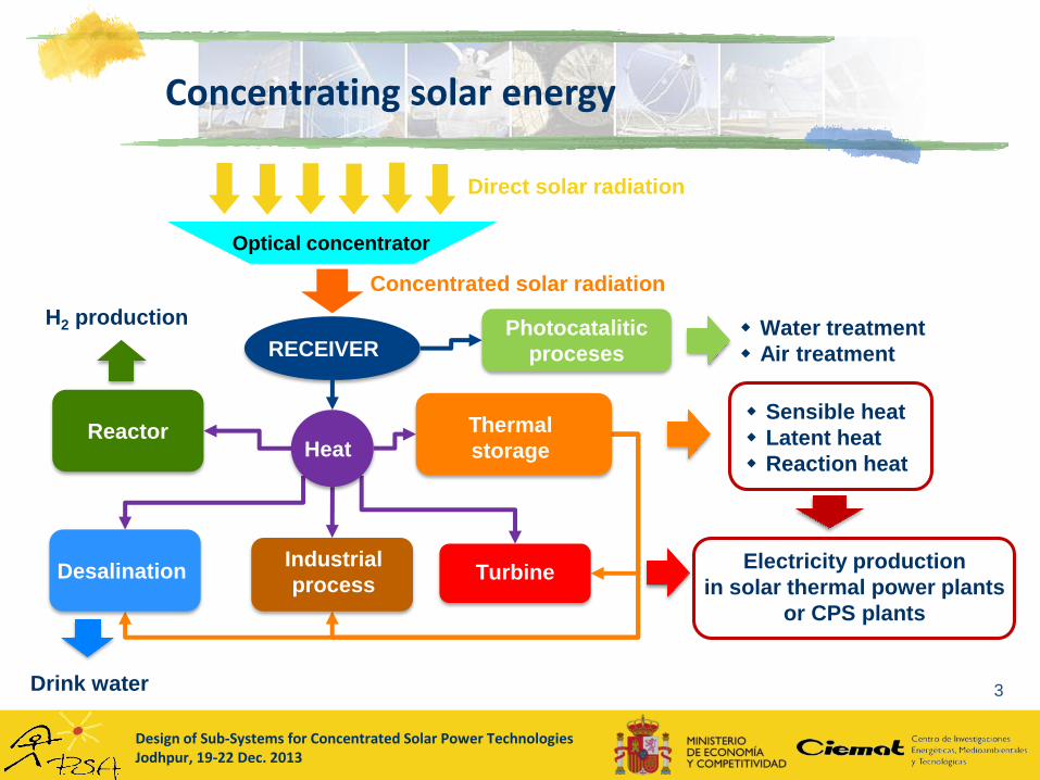
Concentrating solar energy
3
Optical concentrator
Direct solar radiation
Concentrated solar radiation
RECEIVER
Sensible heat
Latent heat
Reaction heat
H2 production
DesalinationIndustrial
processTurbine
Reactor
Drink water
Heat
Water treatment
Air treatment
Photocatalitic
proceses
Thermal
storage
Electricity production
in solar thermal power plants
or CPS plants

Design of Sub-Systems for Concentrated Solar Power TechnologiesJodhpur, 19-22 Dec. 2013
Thermal storage
system
Power
block
(P, T, )
HTF
HTF
HTF
Charge process
HTF
Thermal storage in a CSP plants: how it works?
Thermal storage
system
Power
block
(P, T, )
HTF
HTF
Discharge process
Design of Sub-Systems for Concentrated Solar Power TechnologiesJodhpur, 19-22 Dec. 2013
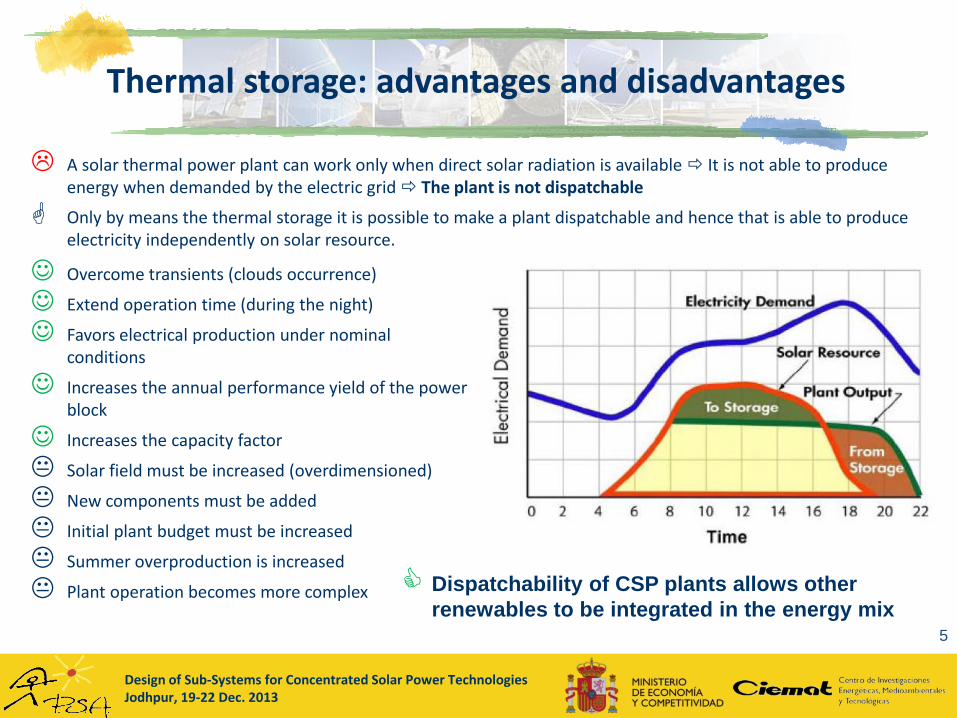
Thermal storage: advantages and disadvantages
5
Overcome transients (clouds occurrence)
Extend operation time (during the night)
Favors electrical production under nominal conditions
Increases the annual performance yield of the power block
Increases the capacity factor
Solar field must be increased (overdimensioned)
New components must be added
Initial plant budget must be increased
Summer overproduction is increased
Plant operation becomes more complex
A solar thermal power plant can work only when direct solar radiation is available It is not able to produce energy when demanded by the electric grid The plant is not dispatchable
Only by means the thermal storage it is possible to make a plant dispatchable and hence that is able to produce electricity independently on solar resource.
Dispatchability of CSP plants allows other
renewables to be integrated in the energy mix

Design of Sub-Systems for Concentrated Solar Power TechnologiesJodhpur, 19-22 Dec. 2013
Effect of thermal storage in plant performance
6
• Identical solar field
• Same electrical
production
• With storage
Production is more
stable
50 MWe with vs. 100 MWe without
Design of Sub-Systems for Concentrated Solar Power TechnologiesJodhpur, 19-22 Dec. 2013
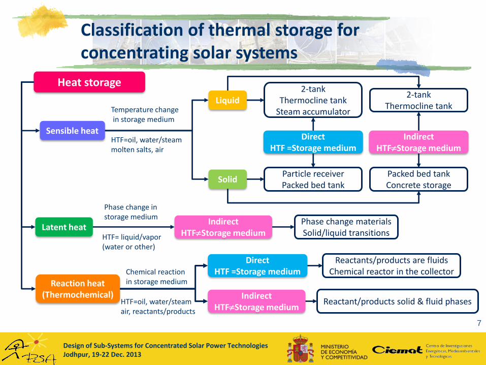
Classification of thermal storage for concentrating solar systems
7
Heat storage
Sensible heat
Reaction heat(Thermochemical)
Latent heat
Solid
LiquidTemperature changein storage medium
Phase change in storage medium
DirectHTF =Storage medium
IndirectHTFStorage medium
Chemical reaction in storage medium
DirectHTF =Storage medium
IndirectHTFStorage medium
IndirectHTFStorage medium
2-tank Thermocline tank
Steam accumulator
2-tank Thermocline tank
Packed bed tankConcrete storage
Particle receiverPacked bed tank
HTF=oil, water/steammolten salts, air
HTF= liquid/vapor(water or other)
Phase change materialsSolid/liquid transitions
HTF=oil, water/steamair, reactants/products
Reactants/products are fluids Chemical reactor in the collector
Reactant/products solid & fluid phases
Design of Sub-Systems for Concentrated Solar Power TechnologiesJodhpur, 19-22 Dec. 2013
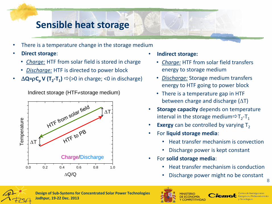
Sensible heat storage
8
• There is a temperature change in the storage medium
• Direct storage:
• Charge: HTF from solar field is stored in charge
• Discharge: HTF is directed to power block
• Q=Cp V (T2-T1) (>0 in charge; <0 in discharge)
• Indirect storage:
• Charge: HTF from solar field transfers energy to storage medium
• Discharge: Storage medium transfers energy to HTF going to power block
• There is a temperature gap in HTF between charge and discharge (T)
• Storage capacity depends on temperature interval in the storage mediumT2-T1
• Exergy can be controlled by varying T2
• For liquid storage media:
• Heat transfer mechanism is convection
• Discharge power is kept constant
• For solid storage media:
• Heat transfer mechanism is conduction
• Discharge power might no be constant
0.0 0.2 0.4 0.6 0.8 1.0
Te
mp
era
ture
Q/Q
Direct storage (HTF=storage medium)
Charge
T1
T2
0.0 0.2 0.4 0.6 0.8 1.0
Te
mp
era
ture
Q/Q
Direct storage (HTF=storage medium)
Discharge
T1
T2
0.0 0.2 0.4 0.6 0.8 1.0
Te
mp
era
ture
Q/Q
Indirect storage (HTFstorage medium)
Charge
T1
T2
0.0 0.2 0.4 0.6 0.8 1.0
Te
mp
era
ture
Q/Q
Indirect storage (HTFstorage medium)
Discharge
T1
T2
0.0 0.2 0.4 0.6 0.8 1.0
Te
mp
era
ture
Q/Q
Indirect storage (HTFstorage medium)
Charge/Discharge
T
T

Design of Sub-Systems for Concentrated Solar Power TechnologiesJodhpur, 19-22 Dec. 2013
Sensible heat storage: requirements & materials
9
• Requirements
• High volumetric thermal capacity: Cp (kJ/m3K)
• Stand for the temperature range of operation
• Low vapor pressure in the temperature range of operation For liquid media
• High thermal conductivity For solid media
• Non explosive or hazardous materials
• Low price materials ($ or €/kWh)
• Liquid media:
• Synthetic oil (=HTF): 1900 kJ/m3K VP1 cannot be used due to its high vapor pressure
• Water: 4200 kJ/m3K good for low temperature but for high temperature should be under pressure: 30bar/230ºC; 100bar/311ºC
• Solar salt (w-60%NaNO3+w-40%KNO3): 2800 kJ/m3KStorage medium used in commercial plants
• Solid media:
• Concrete: 2500 kJ/m3K
• Natural rocks or sand: 2300 kJ/m3K
• Vitrified industrial wastes: Cofalit y Plasmalit: 3000 kJ/m3K
Design of Sub-Systems for Concentrated Solar Power TechnologiesJodhpur, 19-22 Dec. 2013
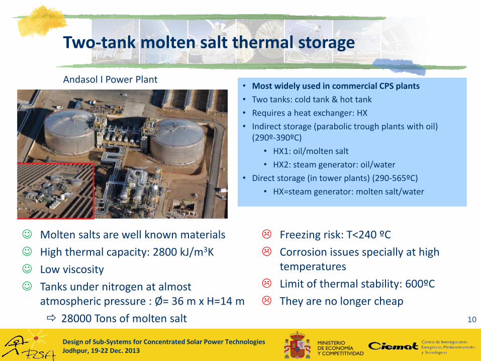
Two-tank molten salt thermal storage
10
• Most widely used in commercial CPS plants
• Two tanks: cold tank & hot tank
• Requires a heat exchanger: HX
• Indirect storage (parabolic trough plants with oil) (290º-390ºC)
• HX1: oil/molten salt
• HX2: steam generator: oil/water
• Direct storage (in tower plants) (290-565ºC)
• HX=steam generator: molten salt/water
Molten salts are well known materials
High thermal capacity: 2800 kJ/m3K
Low viscosity
Tanks under nitrogen at almost atmospheric pressure : Ø= 36 m x H=14 m
28000 Tons of molten salt
Freezing risk: T<240 ºC
Corrosion issues specially at high temperatures
Limit of thermal stability: 600ºC
They are no longer cheap
Andasol I Power Plant
Design of Sub-Systems for Concentrated Solar Power TechnologiesJodhpur, 19-22 Dec. 2013
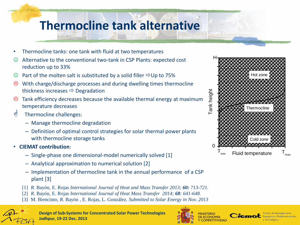
Thermocline tank alternative
[1] R. Bayón, E. Rojas International Journal of Heat and Mass Transfer 2013; 60: 713-721.
[2] R. Bayón, E. Rojas International Journal of Heat Mass Transfer 2014; 68: 641-648.
[3] M. Biencinto, R. Bayón , E. Rojas, L. González. Submitted to Solar Energy in Nov. 2013
Tmax
Tmin
0
Ta
nk h
eig
ht
Fluid temperature
H
Hot zone
Cold zone
Thermocline
Tmax
Tmin
0
Ta
nk h
eig
ht
Fluid temperature
H
Hot zone
Cold zone
Thermocline
• Thermocline tanks: one tank with fluid at two temperatures
Alternative to the conventional two-tank in CSP Plants: expected cost reduction up to 33%
Part of the molten salt is substituted by a solid filler Up to 75%
With charge/discharge processes and during dwelling times thermocline thickness increases Degradation
Tank efficiency decreases because the available thermal energy at maximum temperature decreases
Thermocline challenges:
– Manage thermocline degradation
– Definition of optimal control strategies for solar thermal power plants with thermocline storage tanks
• CIEMAT contribution:
– Single-phase one dimensional-model numerically solved [1]
– Analytical approximation to numerical solution [2]
– Implementation of thermocline tank in the annual performance of a CSP plant [3]
Design of Sub-Systems for Concentrated Solar Power TechnologiesJodhpur, 19-22 Dec. 2013
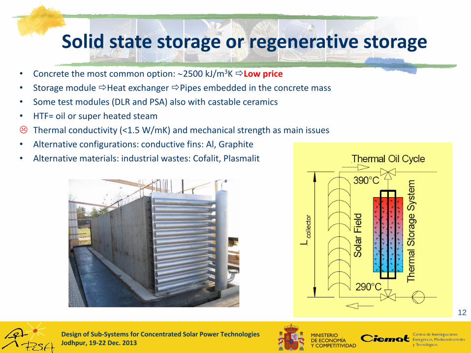
Solid state storage or regenerative storage
12
• Concrete the most common option: 2500 kJ/m3K Low price
• Storage module Heat exchanger Pipes embedded in the concrete mass
• Some test modules (DLR and PSA) also with castable ceramics
• HTF= oil or super heated steam
Thermal conductivity (<1.5 W/mK) and mechanical strength as main issues
• Alternative configurations: conductive fins: Al, Graphite
• Alternative materials: industrial wastes: Cofalit, Plasmalit
Design of Sub-Systems for Concentrated Solar Power TechnologiesJodhpur, 19-22 Dec. 2013
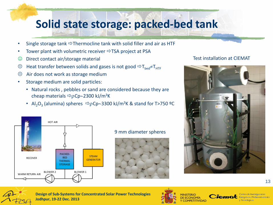
Solid state storage: packed-bed tank
13
• Single storage tank Thermocline tank with solid filler and air as HTF
• Tower plant with volumetric receiver TSA project at PSA
Direct contact air/storage material
Heat transfer between solids and gases is not good TbedTHTF
Air does not work as storage medium
• Storage medium are solid particles:
• Natural rocks , pebbles or sand are considered because they are cheap materials Cp2300 kJ/m3K
• Al2O3 (alumina) spheres Cp3300 kJ/m3K & stand for T>750 ºC
9 mm diameter spheres
Test installation at CIEMAT
STEAM GENERATOR
PACKED-BED
THERMAL STORAGE
HOT AIR
BLOWER 1BLOWER 2WARM RETURN AIR
RECEIVER
Design of Sub-Systems for Concentrated Solar Power TechnologiesJodhpur, 19-22 Dec. 2013
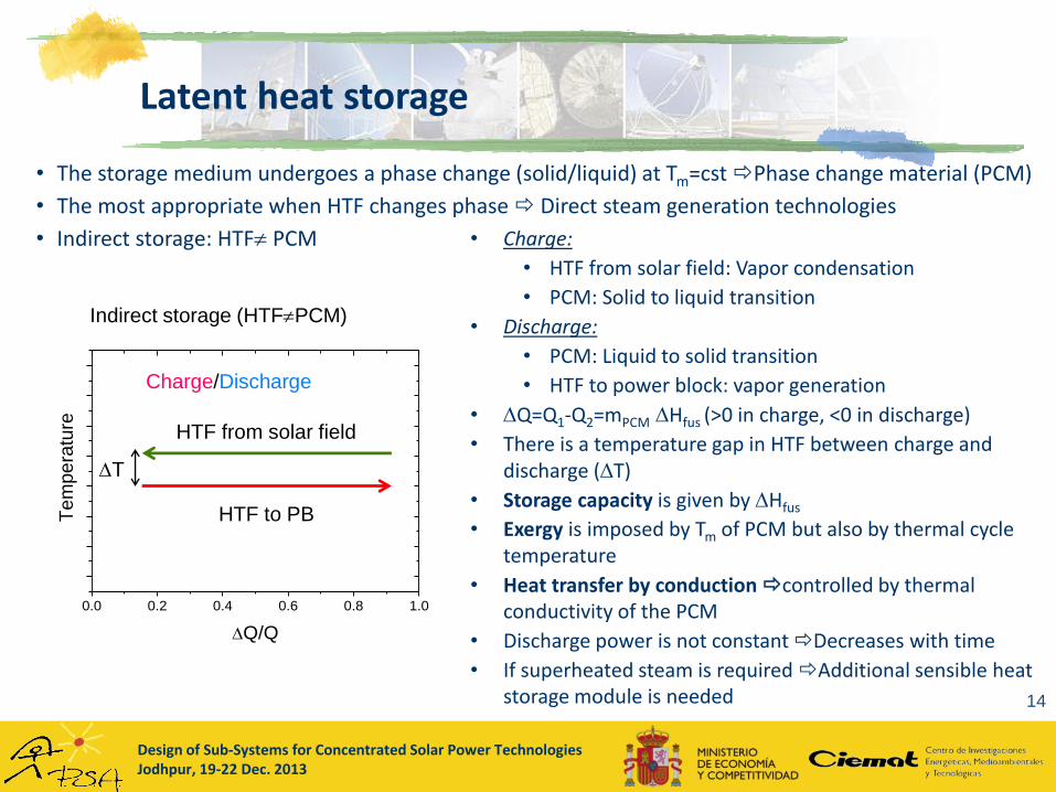
Latent heat storage
14
• The storage medium undergoes a phase change (solid/liquid) at Tm=cstPhase change material (PCM)
• The most appropriate when HTF changes phase Direct steam generation technologies
• Indirect storage: HTF PCM
0.0 0.2 0.4 0.6 0.8 1.0
Te
mp
era
ture
Q/Q
Indirect storage (HTFPCM)
Charge
HTF from solar field
Tm
PCM: SolidLiquid
0.0 0.2 0.4 0.6 0.8 1.0
Te
mp
era
ture
Q/Q
Indirect storage (HTFPCM)
Discharge
HTF to PB
Tm
PCM: Liquid Solid
0.0 0.2 0.4 0.6 0.8 1.0
Te
mp
era
ture
Q/Q
Indirect storage (HTFPCM)
Charge/Discharge
HTF to PB
T
HTF from solar field
• Charge:
• HTF from solar field: Vapor condensation
• PCM: Solid to liquid transition
• Discharge:
• PCM: Liquid to solid transition
• HTF to power block: vapor generation
• Q=Q1-Q2=mPCM Hfus (>0 in charge, <0 in discharge)
• There is a temperature gap in HTF between charge and discharge (T)
• Storage capacity is given by Hfus
• Exergy is imposed by Tm of PCM but also by thermal cycle temperature
• Heat transfer by conduction controlled by thermal conductivity of the PCM
• Discharge power is not constant Decreases with time
• If superheated steam is required Additional sensible heat storage module is needed
Design of Sub-Systems for Concentrated Solar Power TechnologiesJodhpur, 19-22 Dec. 2013
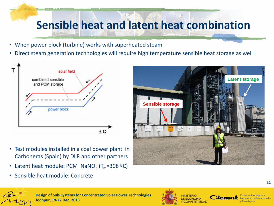
Sensible heat and latent heat combination
15
• When power block (turbine) works with superheated steam
• Direct steam generation technologies will require high temperature sensible heat storage as well
• Test modules installed in a coal power plant in Carboneras (Spain) by DLR and other partners
• Latent heat module: PCM NaNO3 (Tm=308 ºC)
• Sensible heat module: Concrete
T
Sensible storage
Latent storage
Design of Sub-Systems for Concentrated Solar Power TechnologiesJodhpur, 19-22 Dec. 2013
Latent heat storage: requirements & materials
16
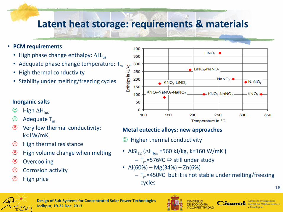
• PCM requirements
• High phase change enthalpy: Hfus
• Adequate phase change temperature: Tm
• High thermal conductivity
• Stability under melting/freezing cycles
Inorganic salts
High Hfus
Adequate Tm
Very low thermal conductivity: k<1W/mK
High thermal resistance
High volume change when melting
Overcooling
Corrosion activity
High price
Metal eutectic alloys: new approaches
Higher thermal conductivity
• AlSi12 (Hfus =560 kJ/kg, k=160 W/mK )
– Tm=576ºC still under study• Al(60%) – Mg(34%) – Zn(6%)
– Tm=450ºC but it is not stable under melting/freezing cycles
Design of Sub-Systems for Concentrated Solar Power TechnologiesJodhpur, 19-22 Dec. 2013
17
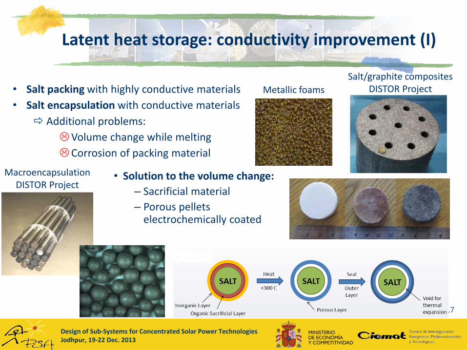
• Salt packing with highly conductive materials
• Salt encapsulation with conductive materials
Additional problems:
Volume change while melting
Corrosion of packing material
Salt/graphite compositesDISTOR ProjectMetallic foams
• Solution to the volume change:
– Sacrificial material
– Porous pellets electrochemically coated
Latent heat storage: conductivity improvement (I)
MacroencapsulationDISTOR Project
Design of Sub-Systems for Concentrated Solar Power TechnologiesJodhpur, 19-22 Dec. 2013
Latent heat storage: conductivity improvement (II)
18
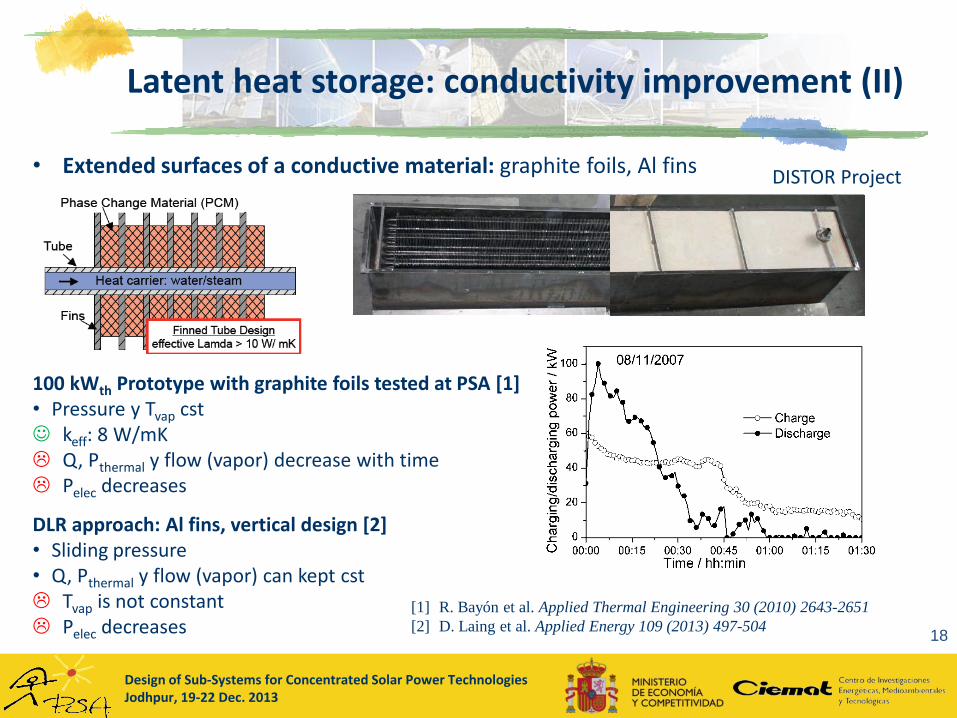
• Extended surfaces of a conductive material: graphite foils, Al fins
100 kWth Prototype with graphite foils tested at PSA [1]• Pressure y Tvap cst keff: 8 W/mK Q, Pthermal y flow (vapor) decrease with time Pelec decreases
DLR approach: Al fins, vertical design [2]• Sliding pressure• Q, Pthermal y flow (vapor) can kept cst Tvap is not constant Pelec decreases
[1] R. Bayón et al. Applied Thermal Engineering 30 (2010) 2643-2651
[2] D. Laing et al. Applied Energy 109 (2013) 497-504
DISTOR Project
Design of Sub-Systems for Concentrated Solar Power TechnologiesJodhpur, 19-22 Dec. 2013
Latent heat storage: heat exchange improvement
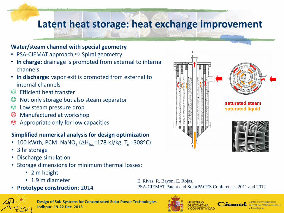
Water/steam channel with special geometry• PSA-CIEMAT approach Spiral geometry• In charge: drainage is promoted from external to internal
channels• In discharge: vapor exit is promoted from external to
internal channels Efficient heat transfer Not only storage but also steam separator Low steam pressure drop Manufactured at workshop Appropriate only for low capacities
saturated steam
saturated liquid
E. Rivas, R. Bayon, E. Rojas,
PSA-CIEMAT Patent and SolarPACES Conferences 2011 and 2012
Simplified numerical analysis for design optimization• 100 kWth, PCM: NaNO3 (Hfus=178 kJ/kg, Tm=308ºC)• 3 hr storage • Discharge simulation • Storage dimensions for minimum thermal losses:
• 2 m height• 1.9 m diameter
• Prototype construction: 2014

Design of Sub-Systems for Concentrated Solar Power TechnologiesJodhpur, 19-22 Dec. 2013
Latent heat storage: moving PCM
• Innolat Project : Fraunhofer ISE
• Screw heat exchanger
• Both heat and material transport
• Self-cleaning
• CIEMAT approach:
• Use of liquid crystals as PCMs
• Liquid/liquid transitions Both phases can move
• 2-tanks with HX configuration
V. Zipf, et al.
Applied Energy DOI: 10.1016/j.apenergy.2012.11.044
R. Bayón, E. Rojas.
International Journal of Energy Research 37 (2013) 1737-1742
Design of Sub-Systems for Concentrated Solar Power TechnologiesJodhpur, 19-22 Dec. 2013
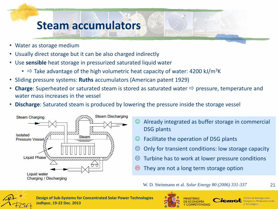
Steam accumulators
21
• Water as storage medium
• Usually direct storage but it can be also charged indirectly
• Use sensible heat storage in pressurized saturated liquid water
• Take advantage of the high volumetric heat capacity of water: 4200 kJ/m3K
• Sliding pressure systems: Ruths accumulators (American patent 1929)
• Charge: Superheated or saturated steam is stored as saturated water pressure, temperature and water mass increases in the vessel
• Discharge: Saturated steam is produced by lowering the pressure inside the storage vessel
Already integrated as buffer storage in commercial DSG plants
Facilitate the operation of DSG plants
Only for transient conditions: low storage capacity
Turbine has to work at lower pressure conditions
They are not a long term storage option
W. D. Steinmann et al. Solar Energy 80 (2006) 331-337
Design of Sub-Systems for Concentrated Solar Power TechnologiesJodhpur, 19-22 Dec. 2013
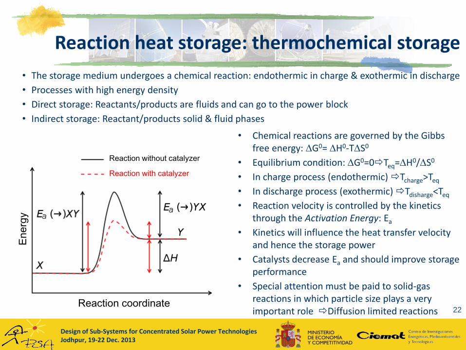
Reaction heat storage: thermochemical storage
22
• The storage medium undergoes a chemical reaction: endothermic in charge & exothermic in discharge
• Processes with high energy density
• Direct storage: Reactants/products are fluids and can go to the power block
• Indirect storage: Reactant/products solid & fluid phases
• Chemical reactions are governed by the Gibbs free energy: G0= H0-TS0
• Equilibrium condition: G0=0Teq=H0/S0
• In charge process (endothermic) Tcharge>Teq
• In discharge process (exothermic) Tdisharge<Teq
• Reaction velocity is controlled by the kinetics through the Activation Energy: Ea
• Kinetics will influence the heat transfer velocity and hence the storage power
• Catalysts decrease Ea and should improve storage performance
• Special attention must be paid to solid-gas reactions in which particle size plays a very important role Diffusion limited reactions
Reaction without catalyzer
Reaction with catalyzer
Energ
y
Reaction coordinate
Design of Sub-Systems for Concentrated Solar Power TechnologiesJodhpur, 19-22 Dec. 2013
Thermochemical storage: criteria for choosing appropriate reactions
23
• The forward reaction for storing the energy should occur with a high yield at Tcharge <TSF
• The reverse reaction for generating heat should occur with a high yield at Tdischarge >TPB
• This implies that Tdischarge < Teq < Tcharge
• Large H0 to maximize storage capacity
• Large S0 to obtain high yield in the reversible reaction Gas products
• Small molar volume of products in order to minimize storage volume
• Completely reversible reactions with no side reactions
• Fast reactions so that the absorption of solar energy and heat regeneration can be carried out rapidly This requires a low activation energy or the use of catalysts.
• For uncatalyzed cases Products must be rapidly separated prior to storage
• For catalyzed reactions Product mixture must be stable
• Simple compound handling, low reactivity with air or water, commercially available and low cost
W.E. Wentworth, E. Chen, Solar Energy 18 (1976) 205-214
Design of Sub-Systems for Concentrated Solar Power TechnologiesJodhpur, 19-22 Dec. 2013
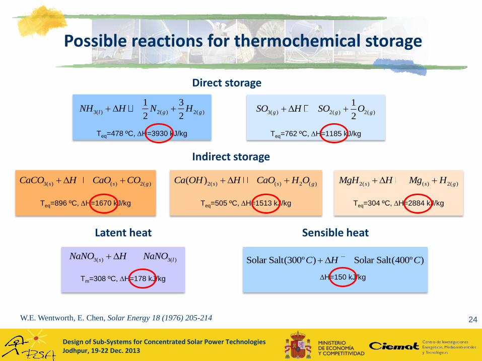
Possible reactions for thermochemical storage
24W.E. Wentworth, E. Chen, Solar Energy 18 (1976) 205-214
Teq=505 ºC, H=1513 kJ/kg
2( ) ( ) 2 ( )( ) s s gCa OH H CaO H O
Teq=478 ºC, H=3930 kJ/kg
3( ) 2( ) 2( )
1 3
2 2l g gNH H N H
Tm=308 ºC, H=178 kJ/kg
3( ) 3( )s lNaNO H NaNO
Teq=896 ºC, H=1670 kJ/kg
3( ) ( ) 2( )s s gCaCO H CaO CO
Teq=304 ºC, H=2884 kJ/kg
2( ) ( ) 2( )s s gMgH H Mg H
3( ) 2( ) 2( )
1
2g g gSO H SO O
Teq=762 ºC, H=1185 kJ/kg
Solar Salt(300º ) Solar Salt(400º )C H C
H=150 kJ/kg
Direct storage
Indirect storage
Latent heat Sensible heat
Design of Sub-Systems for Concentrated Solar Power TechnologiesJodhpur, 19-22 Dec. 2013
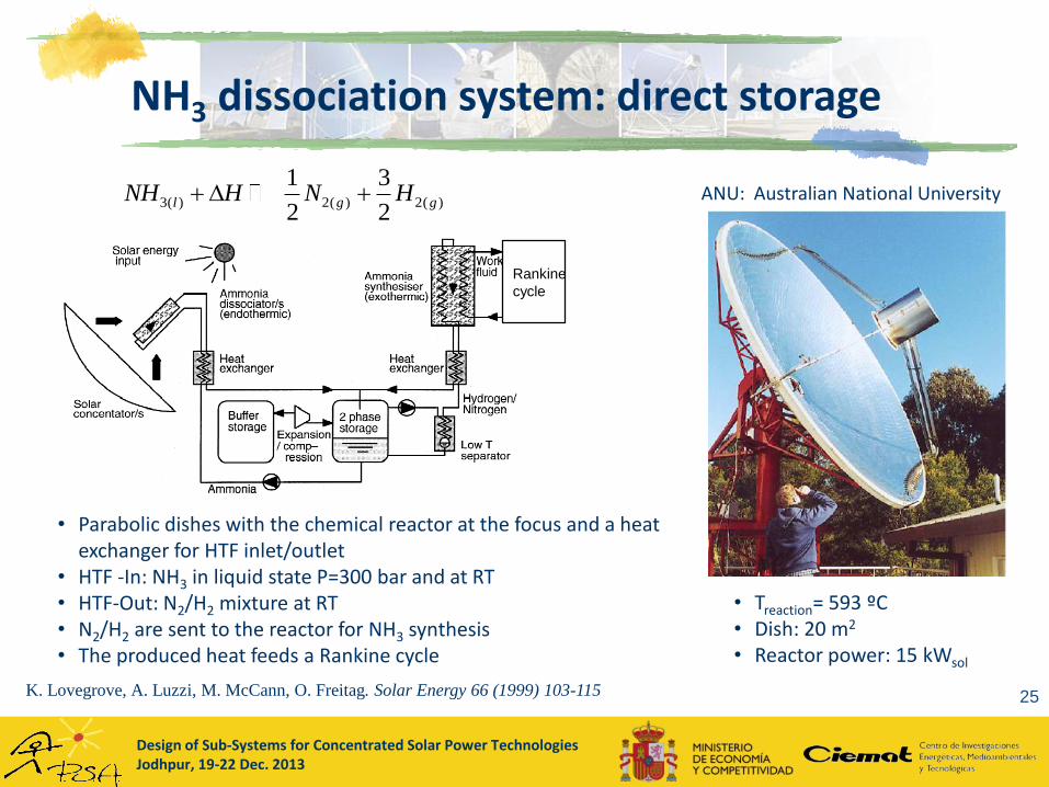
NH3 dissociation system: direct storage
25
• Parabolic dishes with the chemical reactor at the focus and a heat exchanger for HTF inlet/outlet
• HTF -In: NH3 in liquid state P=300 bar and at RT• HTF-Out: N2/H2 mixture at RT• N2/H2 are sent to the reactor for NH3 synthesis• The produced heat feeds a Rankine cycle
ANU: Australian National University
• Treaction= 593 ºC• Dish: 20 m2
• Reactor power: 15 kWsol
K. Lovegrove, A. Luzzi, M. McCann, O. Freitag. Solar Energy 66 (1999) 103-115
Rankine
cycle
3( ) 2( ) 2( )
1 3
2 2l g gNH H N H

Design of Sub-Systems for Concentrated Solar Power TechnologiesJodhpur, 19-22 Dec. 2013
MgH2/Mg system: indirect storage
26M. Felderhoff, B. Bogdanovic, International Journal of Molecular Sciences 10 (2009) 325-344
• HTF: water liquid/vapor, air or no HTF (in charge)• Working temperature depends on reactor pressure• Kinetics limited by H2 diffusion in Mg• Solid reactants in powder Increased reaction surface• It works better with a catalyst: Ni (cyclooctadiene)2
• Hydrogen storage under pressure or low-temp metal hydride
T>450ºC Mg particles are sintered and loose storage capacity
Mg2FeH6/2MgFe grater stability under high temperature cyclingT590 ºC
• Andasol Plant with this kind of storage (7.5 h y 1000 MWhth): 1100 ton of MgH2 vs 28000 ton of molten salts H2(g) storage at 400ºC & 20 bar (109.000 m3) Spherical containers, gas pipelines or geological formations
2( ) ( ) 2( )s s gMgH H Mg H
Equilibrium diagram
Example of plant implementation
Design of Sub-Systems for Concentrated Solar Power TechnologiesJodhpur, 19-22 Dec. 2013
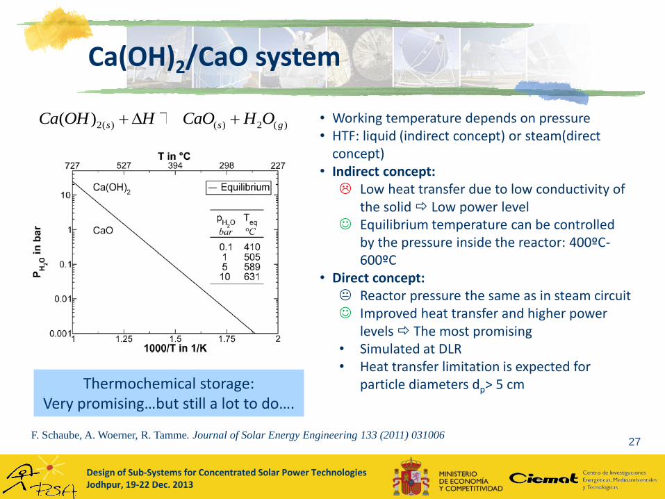
Ca(OH)2/CaO system
27F. Schaube, A. Woerner, R. Tamme. Journal of Solar Energy Engineering 133 (2011) 031006
• Working temperature depends on pressure• HTF: liquid (indirect concept) or steam(direct
concept)• Indirect concept: Low heat transfer due to low conductivity of
the solid Low power level Equilibrium temperature can be controlled
by the pressure inside the reactor: 400ºC-600ºC
• Direct concept: Reactor pressure the same as in steam circuit Improved heat transfer and higher power
levels The most promising• Simulated at DLR• Heat transfer limitation is expected for
particle diameters dp> 5 cm
2( ) ( ) 2 ( )( ) s s gCa OH H CaO H O
Thermochemical storage:Very promising…but still a lot to do….

Design of Sub-Systems for Concentrated Solar Power TechnologiesJodhpur, 19-22 Dec. 2013
Thermal storage challenges and research directions
28
SENSIBLE STORAGE
• Develop heat transfer-storage fluids: Na, Al/Sn
• Use of particles for direct absorption of solar radiation: Particles can be also storage media
• New salt formulations (additives) in order to lower melting point near to ambient temperature
• Low cost container materials for high-temperature storage: corrosion resistant
• Consider alternative materials: intermetallic materials, nanofluids, natural materials (lava, rocks, sands)
LATENT STORAGE
• Investigation of metal alloys as PCMs
• Improve thermal conductivity: new materials or composites
• Micro and nano encapsulation methods
• Develop PCMs for dish/Sterling applications
• Heat pipes
THERMOCHEMICAL STORAGE
• Identification and testing of alternative chemical cycles
• Organic reactions, metallurgical conversions
• Other solid/gas, gas/gas, liquid/gas reactions
Design of Sub-Systems for Concentrated Solar Power TechnologiesJodhpur, 19-22 Dec. 2013
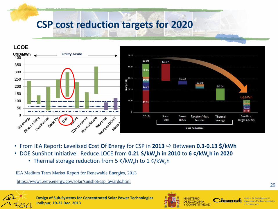
CSP cost reduction targets for 2020
29https://www1.eere.energy.gov/solar/sunshot/csp_awards.html
IEA Medium Term Market Report for Renewable Energies, 2013
• From IEA Report: Levelised Cost Of Energy for CSP in 2013 Between 0.3-0.13 $/kWh• DOE SunShot Initiative: Reduce LOCE from 0.21 $/kWeh in 2010 to 6 ¢/kWeh in 2020
• Thermal storage reduction from 5 ¢/kWeh to 1 ¢/kWeh
LCOE
Design of Sub-Systems for Concentrated Solar Power TechnologiesJodhpur, 19-22 Dec. 2013
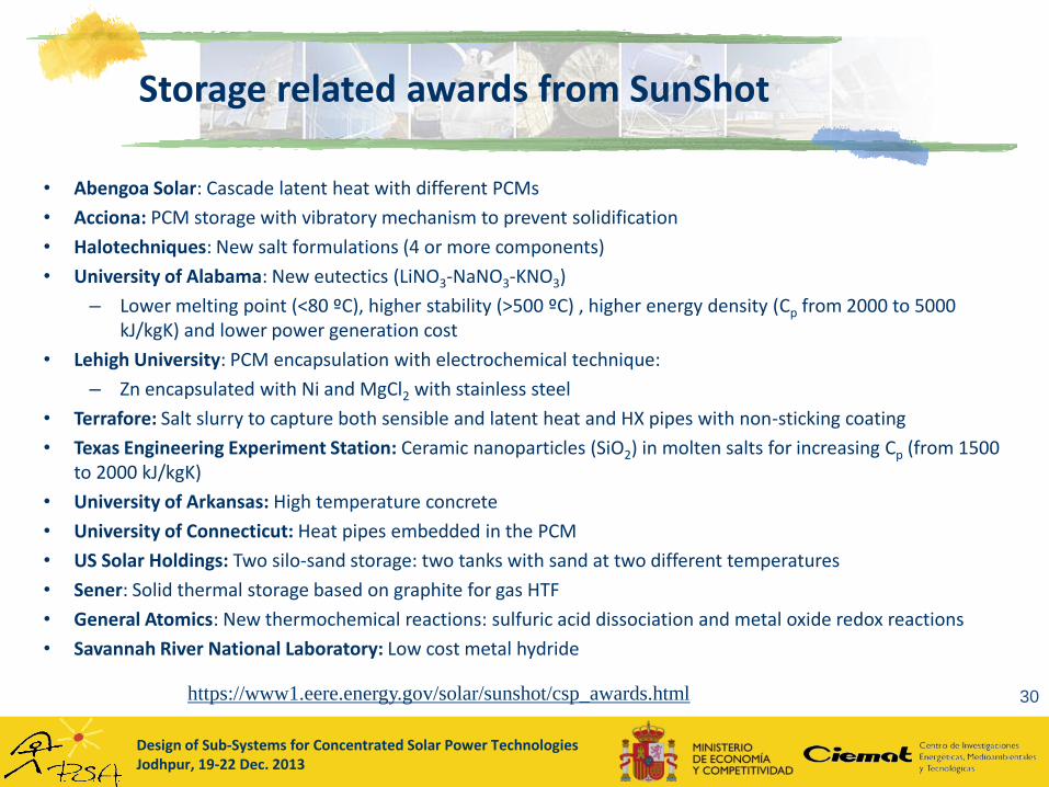
Storage related awards from SunShot
30
• Abengoa Solar: Cascade latent heat with different PCMs
• Acciona: PCM storage with vibratory mechanism to prevent solidification
• Halotechniques: New salt formulations (4 or more components)
• University of Alabama: New eutectics (LiNO3-NaNO3-KNO3)
– Lower melting point (<80 ºC), higher stability (>500 ºC) , higher energy density (Cp from 2000 to 5000 kJ/kgK) and lower power generation cost
• Lehigh University: PCM encapsulation with electrochemical technique:
– Zn encapsulated with Ni and MgCl2 with stainless steel
• Terrafore: Salt slurry to capture both sensible and latent heat and HX pipes with non-sticking coating
• Texas Engineering Experiment Station: Ceramic nanoparticles (SiO2) in molten salts for increasing Cp (from 1500 to 2000 kJ/kgK)
• University of Arkansas: High temperature concrete
• University of Connecticut: Heat pipes embedded in the PCM
• US Solar Holdings: Two silo-sand storage: two tanks with sand at two different temperatures
• Sener: Solid thermal storage based on graphite for gas HTF
• General Atomics: New thermochemical reactions: sulfuric acid dissociation and metal oxide redox reactions
• Savannah River National Laboratory: Low cost metal hydride
https://www1.eere.energy.gov/solar/sunshot/csp_awards.html
Design of Sub-Systems for Concentrated Solar Power TechnologiesJodhpur, 19-22 Dec. 2013
Other storage related projects in different UE institutions
31
• ENEA (Italy):
• Steam generator integrated in a molten salt stratified tank MATS and OPTS Projects
• Fraunhofer ISE (Germany):
• Screw heat exchanger INNOLAT Project
• DLR (Germany):
• PCMs for DSG applications, thermochemical storage, concrete storage, particle receivers
• PROMES (France):
• Vitrified industrial wastes as solid storage materials: Cofalite, Plasmalite
• CIEMAT-PSA (Spain):
• Molten salts test loop for components and operation strategies
• Simulation of thermocline storage and its plant implementation
• New latent storage configurations: spiral HX
• Alternative PCM materials: liquid crystals
• Packed bed storage with air for high temperature applications
• Corrosion tests for molten-salt container materials
Design of Sub-Systems for Concentrated Solar Power TechnologiesJodhpur, 19-22 Dec. 2013
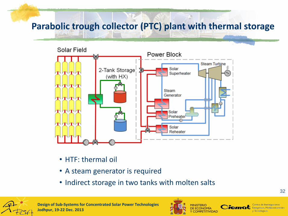
Parabolic trough collector (PTC) plant with thermal storage
32
• HTF: thermal oil
• A steam generator is required
• Indirect storage in two tanks with molten salts
Design of Sub-Systems for Concentrated Solar Power TechnologiesJodhpur, 19-22 Dec. 2013
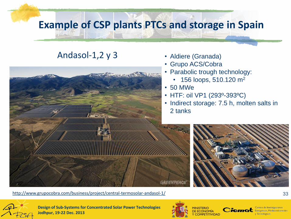
Example of CSP plants PTCs and storage in Spain
33
Andasol-1,2 y 3 • Aldiere (Granada)
• Grupo ACS/Cobra
• Parabolic trough technology:
• 156 loops, 510.120 m2
• 50 MWe
• HTF: oil VP1 (293º-393ºC)
• Indirect storage: 7.5 h, molten salts in
2 tanks
http://www.grupocobra.com/business/project/central-termosolar-andasol-1/
Design of Sub-Systems for Concentrated Solar Power TechnologiesJodhpur, 19-22 Dec. 2013
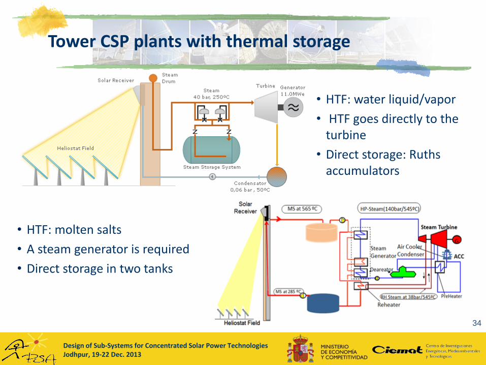
Tower CSP plants with thermal storage
34
• HTF: water liquid/vapor
• HTF goes directly to the turbine
• Direct storage: Ruthsaccumulators
• HTF: molten salts
• A steam generator is required
• Direct storage in two tanks
Design of Sub-Systems for Concentrated Solar Power TechnologiesJodhpur, 19-22 Dec. 2013
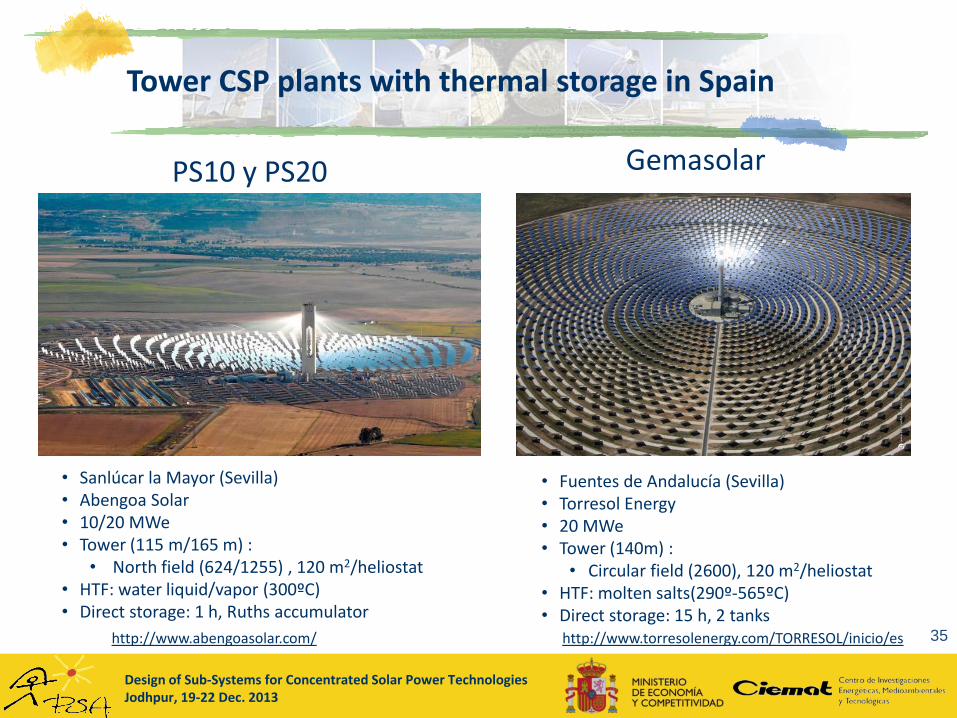
Tower CSP plants with thermal storage in Spain
35
PS10 y PS20
• Sanlúcar la Mayor (Sevilla)• Abengoa Solar• 10/20 MWe• Tower (115 m/165 m) :
• North field (624/1255) , 120 m2/heliostat• HTF: water liquid/vapor (300ºC)• Direct storage: 1 h, Ruths accumulator
Gemasolar
• Fuentes de Andalucía (Sevilla)• Torresol Energy• 20 MWe• Tower (140m) :
• Circular field (2600), 120 m2/heliostat• HTF: molten salts(290º-565ºC)• Direct storage: 15 h, 2 tanks
http://www.torresolenergy.com/TORRESOL/inicio/eshttp://www.abengoasolar.com/
Design of Sub-Systems for Concentrated Solar Power TechnologiesJodhpur, 19-22 Dec. 2013
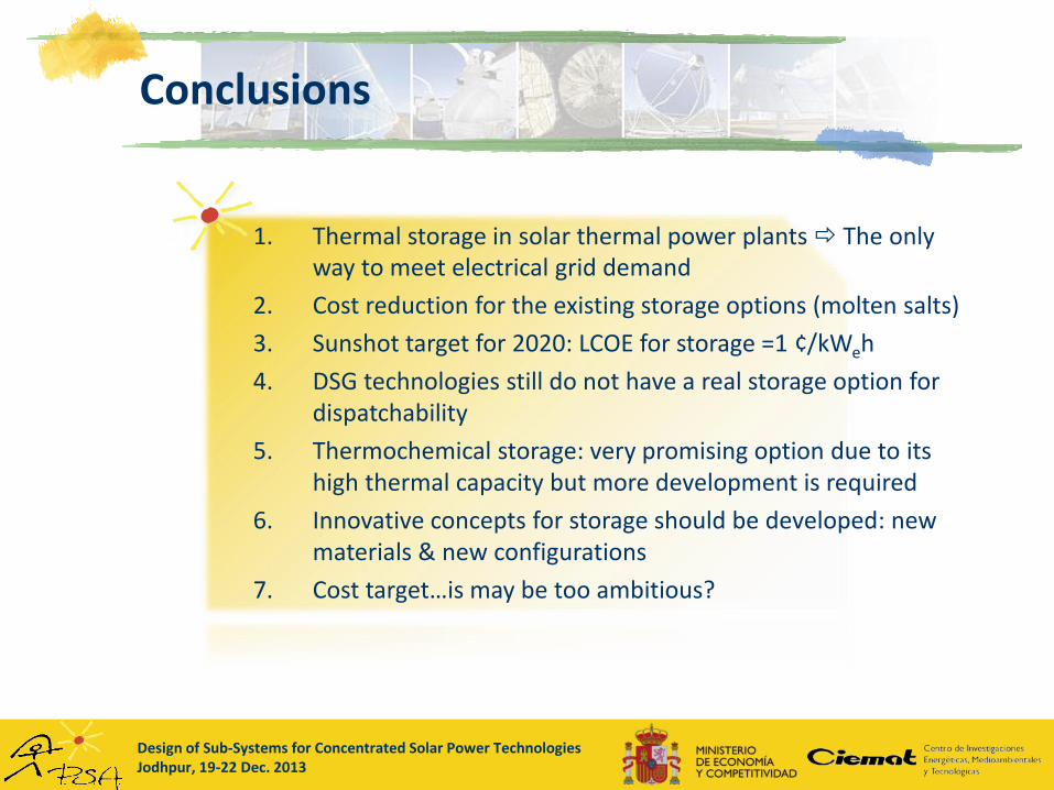
Conclusions
1. Thermal storage in solar thermal power plants The only way to meet electrical grid demand
2. Cost reduction for the existing storage options (molten salts)
3. Sunshot target for 2020: LCOE for storage =1 ¢/kWeh
4. DSG technologies still do not have a real storage option for dispatchability
5. Thermochemical storage: very promising option due to its high thermal capacity but more development is required
6. Innovative concepts for storage should be developed: new materials & new configurations
7. Cost target…is may be too ambitious?
Design of Sub-Systems for Concentrated Solar Power TechnologiesJodhpur, 19-22 Dec. 2013
The End…
Thank you for your attention!
Questions?