thermo-mechanical modeling of draw-bend …
TRANSCRIPT

International Deep Drawing Research GroupIDDRG 2009 International Conference
1-3 June 2009, Golden, CO, USA
THERMO-MECHANICAL MODELING OF DRAW-BENDFORMABILITY TESTS
Ji Hoon Kim I, Ji Hyun Sung2, and R. H. Wagoner3
I Department of Materials Science and Engineeringe-mail: [email protected]
2 Department of Mechanical Engineeringe-mail: [email protected]
3 Department of Materials Science and Engineeringe-mail: [email protected]
The Ohio State University, 2041 College Road, Columbus, OH 43210 USA
ABSTRACTRolling-direction (RD) draw-bend fracture tests of dual-phase (DP) steels utilizing velocity
control of both actuators revealed three patterns of failure depending on draw speed, draw speedratio, and R/t ratio. In particular, shear failure occurs across the strip width just at the contacttangent point with the tooling. Shear failure occurs preferentially for smaller R/t and higherdeformation rates. During draw bend tests, the temperature rises are significant, up 100°C beforenecking, with consequent loss of strength in affected regions. A coupled thermo-mechanicalfinite element (FE) model of the draw-bend test was developed in Abaqus Standard 6.7. Themodel employs 5 layers of solid elements C3D8RT, which have both temperature anddisplacement degrees of freedom. The model is capable of representing softening and alteredstrain hardening of materials measured at elevated temperatures. Such capability was requiredbecause the mechanical properties of advanced high strength steels often change significantlywith time and location during sheet forming processes because of significant deformation heatingassociated with the high plastic work involved. No account of damage mechanics or brittlefracture phenomena was taken. The simulated results were compared with companion draw-bendtests carried out over a range of process conditions. The FE model predicted the observed failuretypes correctly except for the cases lying at the border between observed transitions betweenfracture types. The predicted normalized stress and displacement to failure showed goodagreement with the measurements. It was concluded that coupled thermo-mechanical FEM canaccurately predict displacement to failure, temperatures, strain localization and formability of thetwo materials tested if an accurate constitutive equation is known. No accounting for internaldamage is required. The results show that the unpredicted forming failures seen in die formingoccur because of local temperature increases caused by the work of deformation. Thesetemperature rises cannot currently be simulated by standard commercial sheet-formingsimulation programs and do not occur in low-speed tests used to generate the fonning limitdiagram (FLO), thus the predicted formability using such methods is unrealistically optimistic.
Keywords: Thelmo-Mechanical Finite Element Model; Draw-Bend Fracture Test; Advanced HighStrength Steel; Shear Failure; Thermally Assisted Strain Localization; Constitutive Equation
..... 503 .....
J.II. Kim, J.II. Sung, and R. II. Wagoner
1. INTRODUCTION
DP steels are a class of advanced high strength steel (AHSS) in wide and increasing use inthe automotive industry. Depending on the application and the grade, failures in AHSS are notalways able to be predicted by the usual forming simulation and application of forming limitdiagrams (FLO). Such diagrams represent the forming limit based on localized deformation, ornecking, which has proven successful in predicting failures for conventional sheet steels. Thenew type of failure, so-called "shear fracture", was observed at sharp radii where bending andunbending under tension during forming occurred [I].
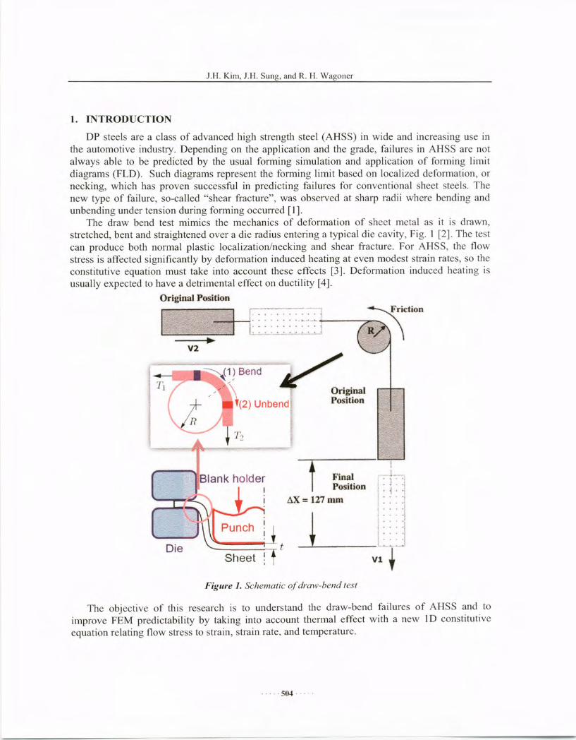
The draw bend test mimics the mechanics of deformation of sheet metal as it is drawn,stretched, bent and straightened over a die radius entering a typical die cavity, Fig. I [2]. The testcan produce both normal plastic localization/necking and shear fracture. For AHSS, the flowstress is affected significantly by deformation induced heating at even modest strain rates, so theconstitutive equation must take into account these effects [3]. Deformation induced heating isusually expected to have a detrimental effect on ductility [4].
Original Position
!1. -j-:-:;
••• '1
~.i . '1.... ,.... i
.... '1' ....
: : : : :1'~. . . .
v~._+...J
FinalPosition
tlX = 127 mOl
i-:-:-: -:-:-.-.-:-~-:~I '.~.'.'.
I~~:.-:.~~~~~.~J
(1)Bend-/
•.. ~ . OriginalU(2) Unbend Position
Ii I
----t.-l.f----,{-
; I
Blank holderII
Die
V2
Figure 1. Schematic aldraw-bend test
The objective of this research is to understand the draw-bend failures of AHSS and toimprove FEM predictability by taking into account thermal effect with a new 10 constitutiveequation relating flow stress to strain, strain rate, and temperature .
..... 504 ....

.I.R Kim, .1.1-1. Sung. and R. 1-1.Wagoner
2. MATERIALS
A dual-phase (DP) steel Dr 980 was used for this study. In order to capture the essentialbehavior, a novel constitutive equation ("H/V") relating flow stress to strain, strain rate, andtemperature was developed as follows:
( Jill
CJ(c,i, T) = [a(T)fHo"o + (1- a(T)). f"oce]';- . [1- D(T - Tin)]Co
(I)
where a(T)=a,-a2(T-TRl')' .I~ollo is Hollomon equation (0"= Ks"), .I;'oce is Voce equation
(0" = A(I- Be-ell»), T and TRT are current and room temperature, respectively, m is a rate
sensitivity parameter varying with strain rate (m =a[logi]+b), and D, aI' and a, are materialconstants. The material parameters used in this study are listed in Table I.
Table 1. Material Parameters/or DP 980.
K (MPa) n A (MPa) B C a,
1,627 0.145 943.4 0.3988 37.85 0.640a2 a b D io (S.l)
0.0025 0.0011 0.0043 0.000298 0.001
3. EXPERIMENTAL PROCEDURE
3.1 Draw-bend fracture test
Novel draw-bend fracture (DBF) testing is based on a modification of draw-bend tests thathave been used for friction and springback testing, as shown in Fig. I. For typical springback orfriction applications, a strip of sheet metal is constrained and bent 90 degree around a roller bytwo grips. While one (back) grip applies constant back force to the sample, the other (front) grippulls the sample away from the roller at a constant speed, V;, so that material moves over theroller under controlled conditions. This test has been applied for draw-bend fracture testing underconstant back force [5,6]. In DBF test developed here, the speed of the back grip, 172, iscontrolled instead of the force as shown in Fig. I. This guarantees the forward movement ofsample, thus fracture always occurs toward the front leg of the specimen (which is notguaranteed otherwise, leading to difficult-to-interpret results). Sheet samples having width of25mm are used with fixed rollers and lubricants to mimic typical fonning processes. The testproceeds until the sample fails, either by tensile plastic localization/necking or by shear failure,depending on the material properties and testing conditions (die radius, draw speeds, sheetthickness ).
3.2 Thermo-mechanical finite clement analysis
A thermo-mechanical finite element model of draw-bend tests was developed to investigatethe failure mechanisms of AHSS deformation, as shown in Fig. 3. The model accounts fordeformation heating and heat transfer and is capable of representing softening and altered strainhardening of materials measured at elevated temperatures. Such capability was required because
..... 50S .....

J.I-I. Kim, J.I-I. Sung, and R. H. Wagoner
temperatures rise much beyond room temperature during draw-bend tests by deformationheating. A symmetric 3D solid model (C3D8RT) was used with 5 layers through thickness inAbaqus 6.7 Standard. Isotropic yield and isotropic hardening were assumed for simplicity.Thermal coefficients were measured from independent experiments or obtained from theliteratures. The friction coefficient was based on a comparison of forces of front grip and backgrip between FE simulation and DBF test using Coulomb friction law.
••
/ hmetal,air = 20W/m2K
Abaqus Standard (V6.7)3D solid elements (C3D8RT), 5 layersVon Mises, isotropic hardeningSymmetric model hmetal,metal = 5kW/m2K
Figure 2. The coupled thermo-mechanicaljinite element modelfor the draw-bend test
4. RESULTS
DBF tests of the DP steel revealed three patterns of failure based on process conditions asshown in Fig. 3: Type I is a standard tensile failure far removed from small radius bendingregions. It occurs in material that has not been bent and unbent over the die radius. Type III iswhat is often called "shear failure" that occurs at the exit tangent point with little deformation inthe width direction, in a direction perpendicular to the strip axis. Type II has a mixed appearancethat appears to initiate like Type III but propagates at an angle in material that has been drawnover the tooling. Type II and Type III failures, here associated with what are typically calledshear failures, occur preferentially for smaller Rlt and higher deformation rates, Figs. 2 and 3. Inorder to understand the origin of the phenomena involved, temperatures were measured duringdraw bend deformation using thermocouples and an infrared camera. The temperature rises weresignificant, up 100°C at locations near from the localization depending on failure type andforming rate. Therefore, thenno-mechanical analysis using temperature-sensitive constitutiverelations is essential to understanding the behavior.
..... 506. _...

J.I-I. Kim, HI. Sung, and R. 1-1.Wagoner
Figure 3. Three/ai/lire types
Fig. 4 shows the normalized stress-front displacement curve for the case with V; = 5lmm / S,
V2/ V; = 0, and R/t=2.2. The normalized stress is defined as the front force divided by the
product of the initial cross-section area and the ultimate tensile strength (=997 MPa). The stressincreases as the sheet rolls over the roller and the sheet fails at the roller (Type TIl) .
..... 507 .....

J.II. Kim, J.H. Sung, and R. H. Wagoner
1.2Thermo-Mechanical
1 (Type III)II)II)Q)
0.8s..-tJ)'0Q)
0.6 Measured.~ca (Type III)Es.. 0.4 -0z DP980(D)-GA-1.45mm
0.2V1=51mmls, V
2N1=0
R1t=2.2
0 . _~L . •_._,--1-. _._._._L. _._._._ 11~l-_1 I J I_J_1
-5 0 5 10 15 20 25Front Displacement (mm)
Figure 4. Normalized stress vs..Ii'ont displacement.
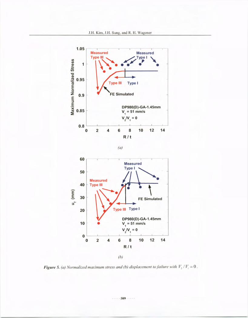
Fig. 5a shows the variation of maximum normalized stress for ~ / ~ = O. For the small R/tratios (R/t < 6), the Type III failure was observed and the maximum normalized stress increasesas R/t increases. For larger R/t ratios (R/t > 6), the Type I failure was observed and the maximumnormalized stress remained constant, close to the ultimate tensile strength.
Fig. 5b shows the variation of displacement to failure for V2 / ~ = 0 . A similar pattern wasobserved: for the small R/t ratios (R/t < 6), the displacement to failure increases as R/t increases,while for larger R/t ratios (R/t > 6), the displacement to failure showed no dependence on R/t.
Fig. 6a shows the variation of maximum normalized stress for V2 / ~ = 0.3. The stress keptincreasing with a decreasing slope as R/t increases and the failure type changes from III to II atR/t of 6. The displacement to failure for ~ / ~ = 0.3 increases as R/t increases, as shown in Fig.
6b.
. .... 508 . - ...
J.l1. Kim. J.I-I. Sung. and R. H. Wagoner
1.05 --'--1--1--'---1--1-
0.9
DP980(D)-GA-1.45mmV = 51 mm/s1
V N =02 1
Measured
fiTypel ". .¥." .
Type III Type I,FE Simulated
MeasuredType III ~\, .
•enE...ozE:JE'xen 0.85~
til
~ 1....•..en"0Q)
.~ 0.95
0.8o 2 4 6 8
R I t
10 12 14
(a)
Type I
'--'---1 --1- .-
DP980(D)-GA-1.45mmV = 51 mm/s1
V N =02 1
10 12 14
~.\
FE Simulated
6 8R I t
60 ---,
50
Measured40 Type III- ~.E
E 30--:J20
10 - •00 2 4
(b)
Figure 5. (a) Normalized maximum stress and (b) displacement to/ai/ure with V2 / ~ = 0 .
..... 509 .....

J.B. Kim, J.B. Sung, and R. B. Wagoner
1.05 -- -,- -,- -_.,--," --,--,-
FE Simulated
Type I
"•
10 12 14
DP980(D)-GA-1.45mmV = 51 mm/s
1
V IV = 0.32 1
MeasuredType II
~t•
6 8R / t
(aJ
42
MeasuredType\\:.. "
C/)C/) 1<II...•..en'U<II.~ 0.95l1:lE...0z 0.9E::JE'x 0.85 "l1:l
:2:
0.80
80 -,--, ----,- -,- -~ _., - ,
60
EE 40
20-
Type I
FE Simulated
DP980(D)-GA-1.45mmV = 51 mm/s1
V IV = 0.32 1
oo 2 4 6 8
R / t(b)
10 12 14
Figure 6. (a) Normalized maximllm stress and (b) displacement to/ai/lire with V2 / V, = 0.3.
The stress-displacement curve predicted using the thermo-mechanical model compared wellwith the measurement, as shown in Fig. 4, while the isothermal model over-predicted thedisplacement to failure by 50%.
The predicted variation of maximum stresses compared well with the measurements, asshown in Figs. 5a and 6a. When V2 / V,= 0 , the thenno-mechanical model correctly predicted thefailure types and captured the transition from Type III to Type I as R/t increases, as shown in
..... 510 .....

1.1-1.Kim, 1.1-1.Sung, and R. 1-1.Wagoner
Fig. Sa. When V2 / ~ = 0.3, however, the thermo-mechanical model did not predicted theobserved Type II failures, as shown in Fig. 6a. The predicted displacement to failure showedgood agreements with the measurements in both cases, regardless of the failure type, as shown inFigs. 5b and 6b.
5. CONCLUSIONS
In order to understand the fundamental mechanisms of the formability behavior of AHSS,novel bi-velocity controlled draw-bend tests were developed and three types of failure includingthe shear failure were reproduced. A coupled thermo-mechanical finite element model of thedraw-bend test was constructed to predict the failures. From the experiments and simulations, thefollowing conclusions were drawn:
• Three kinds of failure patterns were observed for the dual phase steel DP 980depending on process parameters (radius-to-thickness ratio, drawing speed, anddrawing ratio): Type I is a standard tensile failure, Type III is the shear failure thatoccurs in a bending region as material is drawn over a die radius, and Type II is amixed failure that initiates because of acute bending but propagates more like atensile failure.
• Type II or Type III failures occur for small R/t and or higher deformation rates. Themeasured temperature rises during draw-bend are significant, up to 100 ac.
• The developed thermo-mechanical model accurately predicted the failure type,maximum stress, and displacement to failure for DP 980, whereas the isothermalsimulations over-predicted the displacement to failure by 100%. This result suggeststhat thennally assisted strain localization controls the type of failure and its time ofoccurrence.
• No damage mechanics is required to understand and predict the failure ofDP 980.
6. ACKNOWLEDGEMENTSThis work was supported cooperatively by the Department of Energy (Contract DE-FC26-
020R229I 0), the Auto/Steel Partnership, the National Science Foundation (Grant CMMI0727641), and the Transportation Research Endowment Program at the Ohio State University.This work was supported in part by an allocation of computing time from the OhioSupercomputer Center (PAS0080). We are grateful to Amitesh Madeshia for early developmentsof, and measurements using, the fixed-velocity, draw-bend formability test.
7. REFERENCESI. R.H. Wagoner: "Fundamental research issues", Proc. Of NSF Workshop, Arlington, VA, Oct.
22-23, 2006.2. F.F. Damborg, R.H. Wagoner, J. Danckert, and O.K. Matlock: "Stretch bend formability",
Ph.D. Dissertation, Aalborg University, Aalborg, Denmark, 1997.3. S.l. Kim, Y. Lee, and S.M. Byon: "Study on constitutive relation of AISI 4140 steel subject
to large strain at elevated temperatures", Journal of Material Processing Technology 140(2003) 84-89.
4. Y. Gao and R.H. Wagoner: "A simplified model of heat generation during the uniaxialtensile test" Metallurgical. Transactions A 18A (1987) 1001-1009 .
. .. .. 511 .....

J.H. Kim, J.I-I. Sung, and R. H. Wagoner
5. F.F. Damborg, R.H. Wagoner, K.B. Nielsen, J. Danckert: "Application of ductile fracturecriteria to bending under tension", IDDRG 98; Brussels; Belgium; June 17-19, 1998, 145-155.
6. F.F. Damborg: "Prediction of fracture in bending-under-tension", Riso National Laboratory,Modelling of Structure and Mechanics of Materials from Microscale to Product (Denmark),Sept. 1998, 235-240.
. .... 512 .....