thermoelectricity engineering (modules, performance
TRANSCRIPT

HAL Id: hal-02367539https://hal.archives-ouvertes.fr/hal-02367539
Submitted on 18 Nov 2019
HAL is a multi-disciplinary open accessarchive for the deposit and dissemination of sci-entific research documents, whether they are pub-lished or not. The documents may come fromteaching and research institutions in France orabroad, or from public or private research centers.
L’archive ouverte pluridisciplinaire HAL, estdestinée au dépôt et à la diffusion de documentsscientifiques de niveau recherche, publiés ou non,émanant des établissements d’enseignement et derecherche français ou étrangers, des laboratoirespublics ou privés.
Thermoelectricity Engineering (modules, performance,applications)Daniel Champier
To cite this version:Daniel Champier. Thermoelectricity Engineering (modules, performance, applications). Doctoral.France. 2019. hal-02367539

ThermoelectricityEngineering (modules, performance, applications)
Daniel CHAMPIERLaboratoire des Sciences de l’Ingénieur Appliquées à la Mécanique
et au Génie Electrique (SIAME)
Université de Pau et des Pays de l'Adour France
STEIG

Daniel CHAMPIER Thermoelectricity 2
Presentation
•1. Introduction Description of the elements of a thermoelectric generator.
Concept of thermal
Power and Efficiency of thermoelectric generators.
Modules marketed or in the process of being marketed.
•2. Design of thermoelectric generatorsModeling of thermoelectric modules
Complete generator model (from heat sources to electrical storage including electrical converters)
Design and optimization
Study of an example and practical aspects
•3. Applications Production in extreme environments
Waste Heat Recovery (WHR)
Domestic production
Microgeneration: sensors, connected objects (IOT)
Thermoelectric solar power
Cooling
Metrology
Applications of Thermoelectricity
Thermoelectricity

Daniel CHAMPIER Thermoelectricity 3
Market from market research companies
Let's be optimistic

Daniel CHAMPIER Thermoelectricity 4
elements of a thermoelectric generator
figure of merit
One couple of a seebeck module consists of one N-Type and one P-type semiconductor pellet
2.Z
σ αλ
=
2. .TZT
σ αλ
=
Bi2Te3 ZT is about 1
dimensionless figure of merit ZT
σ is the electrical conductivity
λ is the thermal conductivity
ZT is a very convenient figure for comparing the potential efficiency of devices using different materials.Values of ZT=1 are considered good

Daniel CHAMPIER Thermoelectricity 5
elements of a thermoelectric generator
TE modulesindividual couples connected electrically in seriesThermally in parrallel to enhance the effect Semiconductor P and N
N
Ceramic plate
(electric insulation)
P-Type
Semiconductor
Pellets
conducting strip
N-Type
Semiconductor
Pellets
N
P
N
P
≈ 5 cm
≈ 4 mm
≈ 5 cm

Daniel CHAMPIER Thermoelectricity 6
elements of a thermoelectric generator
• Direct Energy Conversion
• No Moving Parts
• No Working Fluids
• Maintenance-free Durability
• High reliability: solid state construction.
• Small size and weight.
• Electrically and acoustically "quiet" Operation
• Operation in any orientation : aerospace and moving applications.
• Extreme climatic conditions (hot, cold, wet, dry)
Advantages of thermoelectric modules

Daniel CHAMPIER Thermoelectricity 7
Design of a ThermoElectric Generator TEG
Hot exchanger
Cold exchanger
7
Thermoelectric
modules

Daniel CHAMPIER Thermoelectricity 8
Thermoelectric (TE) Generators TEG
Heatgenerator
Heatsink
TE modules
Electrical power
(<5%)
Heat source
exchanger exchanger Heat sink
Electronic converterStorage Battery
convert directly a very small part of the heat moving through them into electricity
2)( TPelec ∆= β
Waste Heat
Efficiency is low
AvailableheatCHP

Daniel CHAMPIER Thermoelectricity 9
Generality about Heat Transfer3 Heat Transfer Modes
Heat “flows” to right Q°= Φ heat transfer rate, wattsQ heat, Joules
Thigh Tlow
Solid
1) Conduction heat transfer
2) Convection heat transfer : heat transfer due to a flowing fluid.The fluid can be a gas or a liquid
3) radiation : transmission of energy through space without the necessarypresence of matter.
Picture: University of Wisconsin

Daniel CHAMPIER Thermoelectricity 10
Generality about Heat Transfer
heat reservoirTA
Bar
Conduction heat transfer (steady state case)
heat reservoirTBQ°
Q°= Φ heat transfer rate (W) (flux de chaleur, puissance thermique, flux thermique) is a function
of the temperature of the two reservoirs, the bar geometry and the bar properties.A area of the barL length of the barλ thermal conductivity (W.m-1K-1)Rth Thermal resistanceGth Thermal conductance
Metals Ag Cu Al Fe Steel
λ [W/m-K] 420 390 200 70 50
Non-Metals H2O Air Brics Wood Cork
λ [W/m-K] 0.6 0.026 0.4-0.5 0.2 0,04
Solid
Solid means no moving particles

Daniel CHAMPIER Thermoelectricity 11
Generality about Heat Transfer
Analogy Heat transfer and Electricity
UaUb
I Relec
λ thermal conductivity (W.m-1K-1) σ electrical conductivity (S/m)
Almost perfectinsulation
Convection, radiation and lossare also here
(K.W-1)
(W)

Daniel CHAMPIER Thermoelectricity 12
Generality about Heat Transfer
heat reservoirTA
Conduction heat transfer (steady state case)
heat reservoirTBQ°
R1
Tx
0 Lx
Tx
x
TA
TB
the temperature decreases linearly

Daniel CHAMPIER Thermoelectricity 13
Generality about Heat Transfer
heat reservoirTA
Conduction heat transfer (steady state case)
heat reservoirTBQ°
R2 R1
R=R1+R2
TC
0 Lx
Tx
x
TA
TB
C
TC
The slope of the curve change

Daniel CHAMPIER Thermoelectricity 14
Generality about Heat TransferConduction heat transfer (steady state case)
= −
=
+ +
− =
+ +
A A X Y B B0
50
100
150
200
250
Tem
pera
ture
°C
position cm
R1=R3R2=8.R1
A A X Y B B0
50
100
150
200
250
Tem
pera
ture
°C
position cm
R1=R3R2=4.R1
∆T ∆T
1 module P=K ∆T2 2 modules P=2K ∆T’2

Daniel CHAMPIER Thermoelectricity 15
Generality about Heat TransferConvective heat transfer
air moving near a blade or a fin for example
Region of thickness δ′ : thin "film" of slowly moving fluid most of the temperature difference occurs.
Outside this layer, T is roughly uniform
fin
air
= . . − h : convective heat transfer coefficient (W/m2K)h is known mainly through experiments

Daniel CHAMPIER Thermoelectricity 16
Generality about Heat Transfer
Convective heat transfer
= . . − h : convective heat transfer coefficient (W/m2K)h is known mainly through experiments
Typical values =
1
.

Daniel CHAMPIER Thermoelectricity 17
Generality about Heat Transfer
Radiation Heat Transfer
All bodies radiate energy in the form of photons moving in a random direction, with random phase and frequency. When radiated photons reach another surface, they may either be absorbed, reflected or transmitted.
transfer between gray, planar, surfaces T1 T2
=. .
−
1
+1
− 1
σ is the Stefan-Boltzmann constantσ = 5.67.10-8 W/m2K4
ε emissivity : property of materialT1 and T2 : Kelvin
Material Emissivity
Aluminum polished 0.03
Aluminum Heavily oxidized 0.2 - 0.33
Asphalt 0.88
Brick 0.90
Concrete, rough 0.91
Copper, polished 0.04
Copper, oxidized 0.87
Paint 0.8 -0.96
Paper white 0.95 to 0.98

Daniel CHAMPIER Thermoelectricity 18
Maximun Power and Efficiency
= ∆ σ α .
. . .Max 2 2elec
NAW T
8L
Dependence upon the temperaturedifference across the thermoelements
Construction :number of thermoelementscross-sectional area length of each element.
‘‘power factor’’ : type of TE material
elec
thermal
W T 1 zT 1TcTh 1 zTTh
∆ + −η = =Φ + +
max .
Efficiency is a function of zT
Electrical Power
Efficiency
Efficiency is low
These results will be explained in detail later
α σ α= =ρλ λ
.2 2z
+= ( )Th TcT
2
Main goalsAugment ZT
Augment ∆T

Daniel CHAMPIER Thermoelectricity 19
ZT of Materials
* Shuo Chen, Zhifeng Ren Recent progress of half-Heusler for moderate temperature thermoelectric applications materialstoday
Industrial ingot (Thermonamic 2015)
Overview of ZT vs temperature for different thermoelectric materials *
IndustryLaboratory
Bi2Te3 ZT is about 1the only commercial module available at large scale

Daniel CHAMPIER Thermoelectricity 20
From materials to modules Example of production in laboratory
* Lab-scale pilot line for Thermoelectric Modules based on half-Heusler Compounds J. D. König, M. Kluge, K. Bartholomé, E. Geczi, U. Vetter, M.
Vergez, U. Nussel, K. R. Tarantik
Thermoelectric modules (TEM) based on half-Heusler compounds

Daniel CHAMPIER Thermoelectricity 21
Industrial modulesmanufacturer Materials ∆T Power state T Max
HiZ, Thermonamic, Lairdtech, Marlow, etc.
Bi2 Te3 300 K 20 W 40€-100€ 300 °C historicalScarce
Evident ThermoelectricIsabellenHütte
Half Heusler 500 K 15W Coming soon
Lab available
600°C environmental-friendly, low cost, availability of raw materials
Shanghai Institute of Ceramics
skuterrudites 510 K 25W Coming soon 600°C environmental-friendly, low cost, availability of raw materials
TEGMA skuterrudites Coming soon
TEGNOLOGY Zn4Sb3/Mg2SiSnZintl Phase
105 K 9 mW Available100€
125°C
TECTEG MFR Calcium/Manganese oxide
750 K 12.3W Available 360$
800°C environmental-friendly, low cost, availability of raw materials. Weight : 6g
TECTEG MFR cascade modules
Calcium/Manganese oxides with Bi2Te3
435 K 11 W Available 560$
600°C
Hotblock Onboard silicon based alloy 500 K 3.6W Available 200€
600°C environmental-friendly, low cost, availability of raw materials. Weight : 6g
Romny Scientific magnesium silicide low $/Watt
Alphabet Energy p-type tetrahedritesn-type magnesium silicide (Mg2Si)
Coming soon Tetrahedrite is a naturally occurring p-type mineral
Organics TEG low Still in lab 130°

Daniel CHAMPIER Thermoelectricity 22
Market for TEG
Global Thermoelectric Generator (TEG) Modules Sales Market Research Report 2018 to 2025
Published (2018) By: QY RESEARCH
Nidhi Bhawsar June 26, 2018
Thermoelectric Modules Market- Leader

Daniel CHAMPIER Thermoelectricity 23
List of Thermoelectric / Peltier Manufactures, Companies and Suppliers major manufacturers
Applied Thermoelectric Solutions LLC
Acal BFI
Adcol Electronic
ADV Engineering
Alflex Technologies
Align Sourcing
Ambient Micro
AMS Technologies
Analog Technologies
Asia Inno
Beijing Huimao Cooling Co., Ltd.
Bentek Systems
BTS Europe
Cidete Ingenieros SL
CUI
Custom Thermoelectric Inc.
Crystal LTD.
European Thermodynamics
Everredtronics Ltd.
Ferrotec Corporation
Gentherm
Gentherm Global Power
Green TEG AG
Guang Dong Fuxin Electronic
Hangzhou Aurin Cooling
Hebei IT
Hicooltec Electronic
Hi-Z Technology, Inc
HotBlock OnBoard
Hui mao
Interm
Kelk Ltd.
Kryotherm
Laird Tech Inc.
II-VI Marlow
INB Thermoelectric
ISA Impex
Innoveco
Merit Technology Group
Micropelt GmbH
Newmark International
OTE International
P&N Tech
Perpetua Power
Phononic
Qinhuangdao Fulianjing
Quick Cool
RFI Corp.
RMT LTD
Sheetak
S&PF Modul
Taicang TE Cooler
TE Technology, Inc.
TEC Microsystems
TECTEG
TEGEOS
TEGPRO Thermoelectric Generator
Termo-Gen AB
Thermal Electronics
Thermalforce
Thermion Company
Thermix
Thermonamic Electronics
Tybang Electronics
UWE Electronic
Wellen Tech
WeTEC
Yamaha
Z-max

Daniel CHAMPIER Thermoelectricity 24
Modeling of thermoelectric modules
Simplified Thermoelectric Equations and properties
Assumptions:The material properties are temperature independentCalculations will be made in steady state conditions
Design of thermoelectric generator

Daniel CHAMPIER Thermoelectricity 25
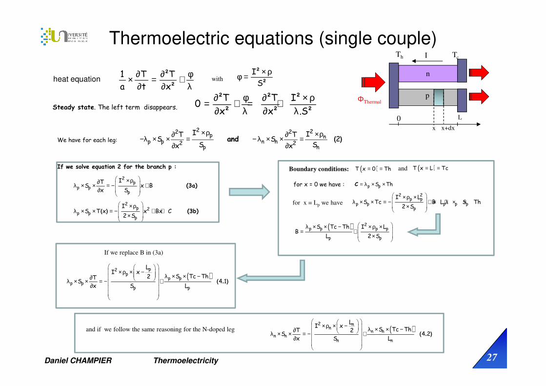
Thermoelectric equations (single couple)
Assumption :all the heat flow between the source and sink takes place within the thermocouple.Thermal radiation and losses by conduction and convection through the surrounding medium are negligible.The two thermocouple branches in our model have constant cross-sectional areas.Thomson effects neglected.
For each branch of the thermoelectric module we have one thermoelectric flow (Peltier ) and a heat flow (conduction) :
p p p p p p p
n n n n
dT dTI S I T S
dx dx(1)
dTI T S
dx
Φ = Π × − λ × × = α × × − λ × ×
Φ = − α × × − λ × ×
λ is the thermal conductivity of the material [W. m-1. K-1],
П is the Peltier coefficient of the material [V]
α is the Seebeck coefficient of the material [V. K-1]
I is the norm of the electric current [A] which explains the minus sign in front.
p
n
I
I
ΦThermal
x0 L

Daniel CHAMPIER Thermoelectricity 26
Thermoelectric equations (single couple)
All the heat flow between the source and sink takes place within the thermocouple. Thus, thermal radiation and losses by conduction and convection through the surrounding medium are negligible.
It is therefore possible to neglect the temperature variations along the axes y and z.
All this brings us to solve a one-dimensional problem along the x axis
The heat equation can be written in this case²T 1 Tx² a t
∂ φ ∂+ = ×∂ λ ∂
heat generation by Joule effectwith 3
W
m
a = λ / cp.ρ is the thermal diffusivity
ρm is the specific weight
p
n
I
ΦThermal
x0 x+dx
Heat equation in Cartesian Coordinates:
Net transfer of thermal energy into the control volume (inflow-outflow)
∂ ∂ ∂ ∂ ∂ ∂ ∂ + + + = ∂ ∂ ∂ ∂ ∂ ∂ ∂ m p
T T T Tc
x x y y z z tλ λ λ φ ρ
Thermal energygeneration
Change in thermalenergy storage
conservation of energy to a differential control volume through which energy transfer is exclusively by conduction.
Cp is the specific heat capacity
control volume : a slice along x
ρ is the electrical resistivity
is the power densityφ
S is the section of a leg
∅ =
!. "⋅ $ ⋅
1
. ". !=
%$
Daniel CHAMPIER Thermoelectricity 27
Thermoelectric equations (single couple)
We have for each leg:
2 22 2p n
p p n n2 2p n
I IT TS S 2
S Sx x
×ρ ×ρ∂ ∂−λ × × = − λ × × =∂ ∂
and ( )
heat equation1 T ²Ta t x²
∂ ∂ φ× = +∂ ∂ λ
with I²S²
× ρφ =
Steady state. The left term disappears.²T ²T I²
0x² x² .S²
∂ φ ∂ × ρ= + = +∂ λ ∂ λ
p
n
I
ΦThermal
x x+dx
L0
Th Tc
If we solve equation 2 for the branch p :
2p
p pp
2p 2
p pp
ITS x B
x S
IS T x x Bx C
2 S
×ρ∂ λ × × = − + ∂
×ρ λ × × = − + + ×
(3a)
(3b)( )
Boundary conditions: ( )= =T x 0 Th ( )= =T x L Tcand
for x = 0 we have :
for x = Lp we have
p pS Th= λ × ×C
× ρ × λ × × = − + × + λ × × ×
2 2p p
p p p p pp
I LS Tc B L S Th
2 S
( ) × ρ × − λ × × − ∂ λ × × = − + ∂
p2p
p pp p
p p
LI x
S Tc Th2TS 4 1
x S L( . )
( ) λ × × − × ρ × = + ×
2p p p p
p p
S Tc Th I LB
L 2 S
If we replace B in (3a)
( ) × ρ × − λ × × −∂ λ × × = − + ∂
2 nn
n nn n
n n
LI x
S Tc ThT 2S 4 2
x S L( . )
and if we follow the same reasoning for the N-doped leg

Daniel CHAMPIER Thermoelectricity 28
Thermoelectric equations (single couple)
( ) × ρ × − λ × × − ∂ λ × × = − + ∂
p2p
p pp p
p p
LI x
S Tc Th2TS 4 1
x S L( . )
By combining (1) and (4):
Φ = α × × − λ × ×p p p pdT
I T S (1)dx
( )
( ) ( )
( ) ( )
× ρ × − λ × × − Φ = α × × + −
× ρ × λ × × −Φ = = α × × − −
×
× ρ × λ × × −Φ = = α × × + −
×
p2p
p pp p
p p
2p p p p
p pp p
2p p p p
p p pp p
LI x
S Tc Th2I T
S L
I L S Tc Thx 0 I Th
2 S L
I L S Tc Thx L I Tc
2 S L
( )
( ) ( )
( ) ( )
× ρ × − λ × × − Φ = −α × × + −
λ × × −× ρ ×Φ = = −α × × − −×
λ × × −× ρ ×Φ = = −α × × + −
×
2 nn
n nn n
n n
2n nn n
n nn n
2n pn n
n p nn n
LI x
S Tc Th2I T
S L
S Tc ThI Lx 0 I Th
2 S L
S Tc ThI Lx L I Tc
2 S L
If we sum and we get the power at the hot side of the system .
Similarly if we sum and we obtain the power at the cold side .
( )p x 0Φ = ( )n x 0Φ = Φh
( )Φ =p x L ( )Φ =p x L cΦ
p
n
I
ΦThermal
x x+dx
L0
Th Tc
( ) ( )
( ) ( )
( ) ( )
2p p p pn n n n
p nhn p n p
2p p p pn n n n
c p nn p n p
2c p nelec h
L SL SII Th Tc Th
S S 2 L L
L SL SII Tc Tc Th
S S 2 L L
W I Th Tc r I
ρ × λ ×ρ × λ × Φ = α − α × × − + − + × −
ρ × λ ×ρ × λ × Φ = α − α × × + + − + × −
= Φ − Φ = α − α × × − − ×
( )
( )
( )
×Φ = α × × − + × −
×Φ = α × × + + × −
= α × × − − ×
2
h
2
c
2elec
r II Th k Th Tc
2
r II Tc k Th Tc
2
W I Th Tc r I
Simplified Thermoelectric Equations for a single couple
With the electrical resistance of a pair of legs PN.
the overall heat transfer coefficient of a pair of legs PN.
the Seebeck coefficient of the thermocouple PN
ρ ×ρ ×= + p pn n
n p
LLr
S S
λ ×λ ×= + p pn n
n p
SSk
L L
α = α − αp n

Daniel CHAMPIER Thermoelectricity 29
Thermoelectric equations (modules)
Assuming that the cross sections of the legs are the same and considering the leg lengths equal we can write:( )n pS S= ( )n pL L=
( )
( )
( )( )
×Φ = α × × − + × −
×Φ = α × × + + × −
= α × × − − ×
.
.
.
2
h
2
c
2elec
r IN I Th k Th Tc
2
r IN I Tc k Th Tc
2
W N I Th Tc r I
( )λ + λ ×=
n p SK N
L( )+ρ ρ ×
=n p L
R NS
Simplified Thermoelectric Equations for a module
N
Ceramic plate
(electric insulation)
P-Type
Semiconductor
Pellets
conducting stripN-Type
Semiconducto
r Pellets
N
P
N
P
The n-type and p-type thermoelements are electrically connected in serie by a conductor, and thermally in parallel. The conductor is assumed to have negligible electrical resistance and thermal resistance.
ρ ×ρ ×= + p pn n
n p
LLr
S S
λ ×λ ×= + p pn n
n p
SSk
L L
α = α − αp n
N number of couples (2N legs)
( )
( )
( )
×Φ = α × × − + × −
×Φ = α × × + + × −
= α × × − − ×
.
.
.
2
h
2
c
2elec
R IN I Th K Th Tc
2
R IN I Tc K Th Tc
2
W N I Th Tc R I
Metal
solders pn n np p
RL : Load
I

Daniel CHAMPIER Thermoelectricity 30
( )= = α ∆
+. . .2 2 2 2L
L 2L
RWelec R I N T
R R
By differentiating Welec with respect to RL we can find the value of load resistance that gives the maximum output power.
( )−∂ = α ∆ =
∂ +
( ). .2 2 2L
3L L
R RWelecN T 0
R R RAdapted load RL=R
( ) ( ) pnpn
2 2 2 2Max 2 2 2 2 2 2 2elec
n p n p
N T NS NS 2 NS NSW T T T T
4 R 8L 8L 8L4L + +
α ∆ α= = ∆ α = ∆ α = ∆ = ∆ σ α
ρρ ρ ρ ρ
. . . . . .. . . . . .
.
( )+ρ ρ ×=
n pN LR
S
Welec can also be written :
+ρ ρρ = n ppn 2
σ σσ = =
ρ σ + σpn
pn
p n
p n
21
we can find the the maximum output power.
!
( )= α −.Voc N Th Tc
A load resistor RL is connected to the module
( )+ρ ρ ×=
n p LR N
S
( )α − α ∆= = =+ + +
. . .oc
L L L
N Th TcV N TI
R R R R R R
( )= α × × − − ×. 2elecW N I Th Tc R I
The module can be modeled as a voltage source Voc with internal resistance R
R
Voc
TC
TH
RL
TE module
Load
VO
I
Maximizing power output from a module
Electrical model of TE module

Daniel CHAMPIER Thermoelectricity 31
Maximizing power output from a module
= ∆ σ α .
. .pn
Max 2 2elec
NSW T
8L
Dependence upon the temperaturedifference across the thermoelements
Construction :number of thermoelementscross-sectional area length of each element.
‘‘power factor’’ : type of TE material
The thermal conductivity, λ, does not appear and so does not directly impact the maximum power.
thermal resistances connecting the thermocouples
to the thermal reservoirs
λ impacts ∆T acrossthe thermocouples.
TE Generator
R
Voc
TC
TH
RL
TE module
Rheostat
VO
I

Daniel CHAMPIER Thermoelectricity 32
Maximizing Efficiency
The input power is the heat entering the hot junction
×= α × ×Φ − + ×∆.2
pnHR I
N I Th K T2
The output power is the electrical energy
( )= = α ∆
+. . .2 2 2 2L
L 2L
RR I N T
R RWelec
Efficiency( )
α ∆+
η = =Φ ×α × × − + × ∆
. .
.
2 2 2L2
L2
Hpn
RN T
R RWelec
R IN I Th K T
2
After some calculations and by defining = LRmR
∆ +η = = + ∆Φ + −+α
.( )
.( ).H
2 2
mWelec T m 1
KR m 1 TTh 12Th m 1N Th
by definingα α σ αα= = = =
ρ λ ρ λ λ..
. . .
2 2 22 2
pn pn
Nz
K R 4
The efficiency becomes∆ +η = + ∆+ −
+
.( )
.( )
mT m 1
m 1 TTh 1ZTh 2Th m 1
Carnot efficiency
Figure of merit
ΦH
pn n np p
RL : Load
IWelec
n p pn2+ρ = ρ ρ = ρ +λ = λ λn p α = α − αp n

Daniel CHAMPIER Thermoelectricity 33
Efficiency for different electrical loadsEfficiency
∆ +η = = + ∆Φ + −+
.( )
.( )H
mWelec T m 1
m 1 TTh 1ZTh 2Th m 1
The load must be adapted
0 1 2 3 4 5 6 7 8 9 100
0.01
0.02
0.03
0.04
0.05
0.06
0.07
m
eff
icie
ncy
Efficiency function of the load
Tc=20°Th=170°C
zT=1
Exemple of efficiency
There is a maximum for m≈1.4
m can be chosen to maximize the efficiency
∂η ∆ − − + ∆=∂ − − − − − + ∆
( ) ..( )
2
2 2
T 2 2m 2zTh 2 Tz Th z
m Th 2zThm 2zTh 2m 4m 2 Tz
∂η = → − − + ∆ =∂
20 2m 2zTh 2 Tz 0m
+ + += = +( )opt
2zTh 2zTc 4 Th Tcm z 1
2 2
= +optm 1 zT
+= ( )Th TcT
2Where T is the average temperature
optT 1 zT 1
TcTh 1 zTTh
∆ + −η =+ +
.
α σ α= =ρλ λ
.2 2z
Maximum of efficiency is a function of zT(Dimensionless figure of merit)
+= ( )Th TcT
2

Daniel CHAMPIER Thermoelectricity 34
Maximum Efficiency
0 0.5 1 1.5 2 2.5 3 3.5 40
0.05
0.1
0.15
0.2
0.25
0.3
0.35
zTeff
icie
ncy
efficiency versus ZT
Tc=20°C
Th=170°C
Carnot efficiency
TE efficiency
0 50 100 150 200 2500
0.05
0.1
0.15
0.2
0.25
0.3
0.35
0.4
0.45
0.5
Temperature diffence Th-Tc K
eff
icie
ncy
Efficiency function of temperature difference
ZT=1ZT=1.5
Carnot efficiency
Tc=20°C

Daniel CHAMPIER Thermoelectricity 35
Complete generator model
From heat sources to electrical storage including electrical converters
1) Adding the heat exchangers to hot and cold sources 2) Electrical converters

Daniel CHAMPIER Thermoelectricity 36
P N P N P N P N P N P N
The thermoelectric elements are inserted between heat exchanger
Exchanger
Exchanger
ThsHeat source
Heat sink Tcs Contact (graphite,
thermal paste)
Céramique
Couples thermoélectrique
Céramique
Contact (graphite,
thermal paste)
Soudure, barrière de diffusion côté froid
Contacts côté froid
Soudure, barrière de diffusion côté chaud
Contacts côté chaud
Heat exchanger
Heat exchanger
Ths
Tcs
Tc
Th

Daniel CHAMPIER Thermoelectricity 37
Tcs
Ths
Tc
Th
Thermoelectric materialWelec
Φ h
Φc
Rhot exchanger
R contact ceramic exchanger
R conduction ceramic
R contact ceramic metal
R conduction metal strip
R conduction metal strip
R contact ceramic metal
R conduction ceramic
Rcold exchanger
R contact ceramic exchanger
Thermoelectric
material
Ro_hot/N
Ro_cold/N
Tcs
Ths
Tc
Th
Welec
Φ h
Φc
Rexch_hot
hot exchanger
Rexch_cold
The TE module is inserted between two heat exchangers.
Ths
Tc
Th
Rth_hot
Welec
Φh
Φc
Tcs
Rth_cold

Daniel CHAMPIER Thermoelectricity 38
Ths
Tc
Th
Rth_hot
Welec
Φh
Φc
Tcs
Rth_cold
(1)
(2)
(3)
(4)
(5)
Thermoelectric Equations
Thermal Equations
&_'( Electrical resistance of a couple including contact resistance
th_'( Thermal resistance of a couple excluding contact resistance
( )
( )
( )
__
__
_
-. . . .
-. . . .
. . - . .
2e pnh
th pn
2c e pn
th pn
2e pnelec
Th Tc1N I Th R I
2 R
Th Tc1N I Tc R I
2 R
W N I Th Tc N R I
Φ = α − +
Φ = α + +
= α × −
( )_
-h
th hot
Ths Th
RΦ =
( )_
-
th cold
Tc Tcsc
RΦ =

Daniel CHAMPIER Thermoelectricity 39
(1) & (4)
(2) & (5)
These two equations can be rewritten in matrix form
Cramer's rule give an explicit formula for the solution of this system of linear equations
Then you can calculate the electrical output power
( ) ( )_
_ _
- -. . . . 2
e pnhth pn th hot
Th Tc Ths Th1N I Th R I
2 R R
Φ = α − + =
( ) ( )_
_ _
- -. . . . 2
e pnth pn th cold
Th Tc Tc Tcs1c N I Tc R I
2 R R
Φ = α + + =
__ _ _ _
__ _ _ _
. . . .
. . . .
2e pn
th hot th pn th pn th hot
2e pn
th pn th cold th pn th cold
1 N N Ths 1N I N R IThR R R R 2
N 1 N Tcs 1N I N R ITcR R R R 2
α + + − + = α − − − −
( ) _. . - . . 2e pnelecW N I Th Tc N R I= α × −

Daniel CHAMPIER Thermoelectricity 40
Cramer's rule
Annex Cramer’s rule
) * ) *
·
" =, ,

Daniel CHAMPIER Thermoelectricity 41
Which values for the material properties ?
Assumptions for the calculations :The material properties are temperature independent
λ, ρ, α as function of the temperature for Thermonamics Ingots
The equations give good results if one chooses the value at the average
temperature.+= = Th Tc
Tav Tm2
λ= λ(Tav) ρ=ρ(Tav) α =α(Tav)
But + +≠Th Tc Ths Tcs
2 2
you have to do some iterations to find Tm
+=( )Ths Tcs
Tm 02
+= ( ) ( )( )
Th 0 Tc 0Tm 1
2
( ) ( )Th 0 et Tc 0
( ) ( )Th 1 et Tc 1
you can make these iterations with I=0 because the average temperature won’t change a lot with I

Daniel CHAMPIER Thermoelectricity 42
Design (and optimization)
Common error
Consider only the power given in manufacturer's datasheet, for example " 19.2W".
19.2 W is for • hot side at 300°C • cold side at 30°C • adapted electrical load
great disappointment
Hot Side Temperature () 300 Cold Side Temperature () 30 Open Circuit Voltage (V) 7.8 Matched Load Resistance (ohms) 0.8 Matched load output voltage (V) 3.9 Matched load output current (A) 4.9 Matched load output power (W) 19.2 Heat flow across the module(W) ≈400Heat flow density(Wcm-2) ≈12.8

Daniel CHAMPIER Thermoelectricity 43
Design (and optimization)
Rough design
- temperatures of the two sources,- thermal resistance of the exchangers- thermal resistance of the modules- No electric current
Calculate the temperature on either side of the modules.
manufacturer curves gives an idea of the power
power will be overestimated : Joule effect, Peltier effect in the module significantly reduce the temperature difference at the faces of the module
This approach has often been used in the past by automotive integrators and has led to disillusionment with the powers obtained.

Daniel CHAMPIER Thermoelectricity 44
Design and optimization
Simplified design
- temperatures of the two sources, Tcs and Ths- thermal resistance of the exchangers- knowledge of the properties of materials
I) Calculation of the average temperature for material properties No electric current
1) Choose Tm =average (Tcs,Ths) and calculate Tc(k=0) and Th(k=0) without current
2) Choose Tm =average (Tc(k=0),Th(k=0)) and calculate Tc(k=1) and Th(k=1) without current
3) Iterate on k (normally just a few time)
II) Calculation of the electric output power
1) Calculate the open circuit voltage Eo (rougth estimation of the maximum output power :-.
/
0) I=0
2) Estimate the short circuit current Imax=Eo/R
3) Calculate the output power for different values of I, between I=0 and Imax using Kramer’s formulas (possibility to iterate on parameters calculation)
4) Calculate the maximum electrical power.

Daniel CHAMPIER Thermoelectricity 45
ExampleThs=500°C Tcs=30 °C
Rexch_hot=1 Rexch_cold=0.05Ro_cold/N = Ro_hot/N = 0.14K/W Rth_hot=1.14; Rth_cold=0.14; Rcontact=0.30 electric contact resistance for the whole moduleMaterial properties of the previous slideN=128 couples
Thermoelectric
material
Ro_hot/N
Ro_cold/N
Tcs
Ths
Tc
Th
Welec
Φ h
Φc
Rexch_hot
hot exchanger
Rexch_cold
Ths
Tc
Th
Rth_hot
Welec
Φh
Φc
Tcs
Rth_cold

Daniel CHAMPIER Thermoelectricity 46
Example : Calculation of the average temperature for material properties
0 1 2 3 4 5 6 7 8 9 10
n iteration
120
140
160
180
200
220
240
260
280calculation of Taverage
Tm
0 1 2 3 4 5 6 7 8 9 10
n iteration
0.92
0.94
0.96
0.98
1
1.02
1.04variation of electrical resistance
Relec module
0 1 2 3 4 5 6 7 8 9 10
n iteration
0.2
0.25
0.3
0.35
0.4
0.45
0.5variation of thermal resistance
Rthm
odule
0 1 2 3 4 5 6 7 8 9 10
n iteration
1
2
3
4
5
6
7variation of open circuit voltage
Voc

Daniel CHAMPIER Thermoelectricity 47
Example : Calculation of the temperatures
0 0.5 1 1.5 2 2.5 3 3.5 4 4.5 5
current (A)
0
50
100
150
200
250
300
350
400
450
500Temperatures in the system
TE cold side
TE hot side
hot source
cold sink
T average
module cold side
module hot side
Values at Maximum Power Point
Delta T = 98.7K Imax = 2.4606A
T moy = 131.15°C
Th = 180.5°C Tc = 81.8°C
values at Open Circuit
Delta T = 116.3K
T moy = 138.65°C
Th = 196.8°C Tc = 80.5°C

Daniel CHAMPIER Thermoelectricity 48
Example : Calculation of electrical power
10.9W 7.4W 7.8W is iteration necessary?
0 0.5 1 1.5 2 2.5 3 3.5 4 4.5 5
current (A)
0
1
2
3
4
5
6
7
8Output Power with simplified model
no iteration
1 or 2 iterations
Values at Maximum Power Point ... 1,2 iterations
Pmax = 7.8W Imax = 2.4606A
Values at Maximum Power Point ... 0 iteration
Pmax = 7.4W
Values using Eo(I=0) ... rough design
Pmax rough = 10.9W

Daniel CHAMPIER Thermoelectricity 49
Design (and optimization)
Remarks on simplified design
- temperatures of the two sources, Tcs and Ths Are they spatially constant ?If not you must cut in different slides
Are they constant over time ?If not, you can consider dynamic equations for the thermal part and keep quasi-static equation for the TE parts
- thermal resistance of the exchangers high uncertainty on convective heat exchange coefficients … difficult part of the job
- knowledge of the properties of materials Some manufacturers give these properties (HiZ, Thermonamic)
Most manufacturers give only: electrical resistance and maximum output power as a function of temperatures but up to now they don’t give the thermal conductance of their modules.
You need to estimated it by your own measurements (Manufacturers started to develop bench measuring Seebeck, Electrical Resistance and Thermal Resistance)

Daniel CHAMPIER Thermoelectricity 50
Optimization : Maximizing power output from a generator
=∆ σ α = ∆ ⋅ ⋅ σ α .
. .pn pn
Max 2 2 2 2elec
NS SW T T N
8L 8L
How many modules to put on? More elegantly how much couple to put in?

Daniel CHAMPIER Thermoelectricity 51
th N couples th pnnp
L 1 1R R
2 S N N= =
⋅ λ
_ _ _. ..Thermal resistance of N couples
Thermal contact + resistance ceramic strip for each couple o o oR R cold R hot= +_ _
If you neglect the Thermoelectric effect (Peltier and Joule) :
Thermal resistance of a module uleth th N couples th pnRo 1
R R R RoN N
= + = +
mod _ _ _( ).
( ) ( ) ( ) ( )ule ule
th pn
th pnth N couples th N couples xccs cs cs cshs hs hs hs
th pnxcth exch cold exch hot thxcth pn
xc
R1RR R NT T T T T T T T T
1 R RoR R R R Ro NN
∆ = − = − = − = −++ + + + + +mod mod
_
__ _ _ _ e
_e_ _e_
e
.R
( )R R( ). R
R
Calculating the temperature difference between the two side of the thermoelectric materials
( ) ( )pn pn pn
2th pn
2th pnMax 2 2 2 2xc
cs cshs hselec 2th pn xcth pn
xc xc
RRS S N S
W T N T T N T TR Ro8L 8L 8LR RoN N
= ∆ ⋅ ⋅ σ α = − ⋅ σ α = − σ α + + + +
_
_e
_ e_
ee
R.
( ) R( )
R R
Rexch_cold
Thermoelectric
material
Ro_hot/N
Ro_cold/N
Tcs
Ths
Tc
Th
Welec
Φ h
Φc
Rexch_hot
hot exchanger
Rthmodule
Optimization : Maximizing power output from a generator

Daniel CHAMPIER Thermoelectricity 52
Rexch_cold
Thermoelectric
material
Ro_hot/N
Ro_cold/N
Tcs
Ths
Tc
Th
Welec
Φ h
Φc
Rexch_hot
hot exchanger
( )pn
2th pnMax 2
cshselec 2xcth pn
xc
RN SW T T
8LR RoN
= − σ α
+ +
_
e_
e
.R( )
R
Maximizing the electrical Power :
∂=
∂
MaxelecW
0N
( )pn
th pn2Max
2th pn 2elec xccshs3
xcth pn
xc
R RoN RW S
T TN 8LR Ro
N
+−
∂= − ⋅ σ α
∂ + +
_
_e
e_
e
( )
R
R( )
R
th pn
xc
R RoN
+= _
e
( )
R
th pnxcule
R RoRth
N
+= =_
emod
( )R
Rthmodule
The temperature difference of the 2 sides of the module is half of the temperature difference between sources.
Strong assumptions : thermoelectric parameters do not depend on temperatureneglecting thermoelectric effect.
pn
2 2th N couplesMax 2cshs
elecule
R T T NSW
th 2 8 L
− == ⋅ σ α
_ _
modR .
Be careful, this relation overestimated the power, because again the temperature difference is calculated by neglecting Peltier and Joule effect.
.
Rule of thumb
Optimization : Maximizing power output from a generator
Thermal impedances matching

Daniel CHAMPIER Thermoelectricity 53
Design and optimization
Complexe design
In the case of non-ideal heat sources (e. g. hot gas cooling along an exchanger), the approach will be to use the TE equations and Thermal equations coupled with fluid dynamics equations.
optimization
Many parameters can be optimized, number of modules, heat exchanger, materials, geometry of modules
Heavy calculations genetic algorithms

Daniel CHAMPIER Thermoelectricity 54
Finite Element Models
Finite Element Software Package : Comsol, Ansys Fluant, etc
Final COMSOL meshFEA model of a thermoelement
junction in COMSOLThe voltage gradient is seen in color
the arrows indicate heat flow
Emil Jose Sandoz-Rosado, Thesis, Improved Modeling of a Thermoelectric Module
The analysis of hundred of thermoelements pairs is highly computationally intensive
The model are limited to a few pairs
a FE model can provide several unique advantages.It can solve the governing set of partial differential equations that cannot be solved analytically.
It permits the investigation of complex geometries.The non-linearities of the material property temperature-dependency can be handled, whereas an analytical solution does not exist.

Daniel CHAMPIER Thermoelectricity 55
Thermoelectric equations : other models
( )
( )
( )
×Φ = α × × − + × −
×Φ = α × × + + × −
= α × × − − ×
2
h
2
c
2elec
r II Th k Th Tc
2
r II Tc k Th Tc
2
W I Th Tc r I
Standard simplified model
( ) ( ) ( )
( ) ( ) ( )
( ) ( ) ( )
×Φ = × × − + × −
×Φ = × × + + ×
α − τ × × −
α + τ × × −
α × − α × × − τ × −
−
= − ×
2
h
2
c
2elec
1Th I Th Tc
2
1Tc I Th Tc
2
Th Th Tc Tc I I Th Tc
r II Th k Th Tc
2
r II Tc k Th Tc
2
W r I
( ) ( )
( ) ( )
( ) ( )
×Φ = α × × − + × −
××
− τ
−Φ = α × + + ×
−
× × −
=
+ τ
×
× ×
− τ
−
α × × −
2
h
2
c
2elec
r II Th k Th Tc
2
r II Tc k Th Tc
2
W
1I Th Tc
2
1I Th Tc
2
I Th Tc r I
∂ατ = ×∂α( )
Tm
TT
+= Th TcTm
2
Thomson simplified model
Thomson Seebeck simplified model
All parameter evaluated at
Seebeck’ surface coefficients
Introducing Thomson’ coefficient
1996 Chen The influence of Thomson effect on the maximum power output and maximum efficiency of a thermoelectric generator

Daniel CHAMPIER Thermoelectricity 56
Power convertor
DC DCConverter
The temperature Th and Tc varies a lot.
An electric power convertor is necessary
output voltage of the TE modules fluctuates a lot.
TE modules
Voc=N.α (Th-Tc)
R=R(Th,Tc)VTE
ITE
Voc
R
TE Generator
The loads need regulated voltage

Daniel CHAMPIER Thermoelectricity 57
Power convertors for TE generators
Power convertors convert electric power from one form to another
DC – DCStep-up (Boost) : The storage voltage is higher than the Te modules voltageBuck-Boost : The storage voltage is higher or lower than the Te modules voltage
TE modules are direct current (DC) sourceLoads are mostly DC (batteries ) but possibly alternating current AC (grid connection)
DC – ACInverter commonly used to supply AC power from DC sources such as solar panels or batteries

Daniel CHAMPIER Thermoelectricity 58
Boost convertor
Vin
Iin
Pulse width
Modulation
Vout
Iout
Voc
R
TE Generator DC/DC convertor Battery + Load
Virtual load
Dc duty cycle : fraction of the commutation period T during which the switch is On.
2T
Vin
Vout
Vin-Vout
VL
Inductance voltage
Inductance current=Iin
DcxT 2T
Switch state
Vin
Vout
Vin-Vout
ILmax
ILmin
VL
IL
Inductance voltage
Inductance current=Iin
DcxT
Switch state
on ononoff off
time
time
time
on off on off
ILmax
ILmin
TT
Average Iin
Vin
Iin = IL
Vout
Iout
Voc
R
SWITCH ON
VL
Vin
Iin = IL
Vout
Iout
Voc
R
SWITCH OFF
VL

Daniel CHAMPIER Thermoelectricity 59
Boost convertor
Vin
Iin
Pulse width
Modulation
Vout
Iout
Voc
R
TE Generator DC/DC convertor Battery + Load
Virtual load
(1 )in outV V Dc= × −
(1 )
out
in
II
Dc=
−
Ideal convertor :
outV is fixed by the battery voltage
The choice of the duty cycle therefore imposes the voltage Vin and thus the currents
For an adapted load (maximum power) Vin must be equal to Voc/2
in in in out out outP V I V I P= × = × =
oc in
in
V VI
R
−=
Voc of the TE modules fluctuates a lot.
The duty cycle needs to follow these variations

Daniel CHAMPIER Thermoelectricity 60
Maximum Power Point (MPP)
R
Voc
TC
TH
Rv
TE module
Virtual Load
Vin
Iin
Electrical Power
0
2
4
6
8
10
12
14
16
0 0,5 1 1,5 2 2,5 3 3,5
Po
we
r W
Voltage Vo (V)
Power versus voltage
Thot=250°C
Thot=200°C
Thot=150°C
Thot=100°C
Tcold =50°C
Voc/2 Voc
Maximum power point
Open circuit voltageand
adapted voltage
Exemple of TE module HiZ 14
Open circuit voltageand
adapted voltage
Voltage Vin (V)
The MMP changes with the temperaturesIntelligence is necessary

Daniel CHAMPIER Thermoelectricity 61
Boost convertor with MPPT
Vin
Iin
Pulse width
Modulation
microcontrollor
Vout
Iout
Voc
R
TE Generator DC/DC convertor Battery + Load
Virtual load
The solution is to control the DC/DC converter with a Maximum Power Point Tracker
Measure Iin
Measure Vin
Calculate Pin
Change duty cycle
Compare with previous Pin
Vin and Iin change
Question : how to change the duty cycle?Algorithm MPPT

Daniel CHAMPIER Thermoelectricity 62
Remarks on electrical part
DC-DC efficiency MPPT efficiency
Optimization of modules (length and area of leg) does not take in account all the components (wires, power convertor, contacts) between modules and end use of the electricity.
Joule effect irreversible and every where
RI2

Daniel CHAMPIER Thermoelectricity 63
Applications
Production in extreme environmentsWaste Heat Recovery (WHR)Domestic productionMicrogeneration: sensors, connected objects (IOT) Thermoelectric solar power
Refrigeration and regulation
Metrology

Daniel CHAMPIER Thermoelectricity 64
Electricity production in extreme environment
critical applications: a power source extremely reliable over very long periods.
extreme climatic conditions:• very hot• very cold• very wet• very dry.
Maintenance as low as possible• helicopter access•several hour trip
Maintenance does not exist in the case of space expeditions.
operation in a vacuum
vibrations.
insensitive to radiation
The cost of watt is not essential

Daniel CHAMPIER Thermoelectricity 65
Space applications
RTG Radioisotope Thermoelectric Generator
Radioisotope Thermoelectric Generators, or RTGs convert the heat generated by the decay ofplutonium-238 (plutonium dioxyde 238PuO2) fuel into electricity
http://solarsystem.nasa.gov/rps/rtg.cfm
GPHS : General Purpose Heat Source module
238Pu fuel pellet
1961 : First use of a thermoelectric generator (Pb -Te) : navigation satellite TransitSNAP-3 (Space Nuclear Auxiliary Power)Electrical power~2,7 wattsworked for more than fifteen years

Daniel CHAMPIER Thermoelectricity 66
Space applications
T. Caillat et al 23rd rd Symposium on Space Nuclear Power and Propulsion STAIF 2006Jet Propulsion Laboratory/California Institute of Technology

Daniel CHAMPIER Thermoelectricity 67
Space applications (Mars exploration)
http://solarsystem.nasa.gov/rps/rtg.cfm
Curiosity’s Radioisotope Thermoelectric GeneratorCuriosity 2mx2mx2mRTG 0.6mx0.6mx0.645kg 110WPbTe Tag

Daniel CHAMPIER Thermoelectricity 68
Space applications
Radioisotope Thermoelectric
Generator RTG
Electric Power
at beginning
of mission per
RTG
Numbe
r of RTGMission destination year
design
lifetimelifetime
Space Nuclear Auxiliary
Power SNAP-3 PbTe2,7 Watts 1 Transit Navigation satellite 1961 15 years
SNAP-19B RTG PbTe-Tags 28.2 Watts 2 Nimbus III meteorological satellite 1969
SNAP-19 RTG
PbTe-Tags
42.6 Watts2 Viking 1 Mars landers 1975 90 days 6 years
2 Viking 2 Mars landers 1975 90 days 4 years
40.3 Watts4 Pioneer 10 Jupiter, asteroid belt 1972 5 years 30 years
4 Pioneer 11 Jupiter Saturn 1973 5 years 22 years
SNAP-27 RTG
PbSnTe70 Watts
Apollo 12, 14,
15, 16 , 17Lunar Surface
1969-
722 years 5-8 years
Multi-Hundred Watt (MHW)
RTG SiGe158 Watts 3 Voyager 1 & 2 edge of solar system 1977
still operating
over 42 years
General Purpose Heat Source
(GPHS) RTG
SiGe
292 Watts
2 Galileo Jupiter 1989 14 years
3 CassiniSaturn
End mission 20171997 21 years
1 Ulysses Jupiter 1990 21 years
1 New HorizonsPluto (12/2014) ,
Kuiper Belt (2019)2006
still operating
after 13 years
Multi-Mission Radioisotope
Thermoelectric Generator
MMRTG PbTe-Tags
110 Watts 1 CuriosityMars Surface
5 Aug 20122011
Expected 14 years

Daniel CHAMPIER Thermoelectricity 69
Space applications
Radioisotope Thermoelectric Generator
• compact• Continuous power sources• Heat exchange on the hot side by conduction (high
temperature)• Used in deep space for several decades• reliable• Use nuclear fuel relatively easy to manipulate Curium-244
and Plutonium-238• Materials used: PbSnTe, PbTe, TAGS, SiGe
Conclusion

Daniel CHAMPIER Thermoelectricity 70
TEG for remote power solutions
REJECTEDHEAT
500 Watts 24 VoltsNatural Gas 48m3/dayPropane 76L/day or 38kg/day
COOLINGFINS
EXHAUSTOUT
LOAD
FUEL IN
T
E
G
F
L
A
M
E
Critical application requiring highly reliable powerLow maintenance requiredLong lifeExtreme climatic conditions (hot, cold, wet, dry)Remote locations
Propane 38kg/dayHeating Value 50MJ/kg
Energy per day= 1900MJ=527kW.h
500 W electric Energy per day= 12 kW.hEfficiency : 2.2 %
April 1, 2014
Pipeline: 550 wattscommunications systemAndes Mountains, Chile
Off shore: 200 wattscommunications and safety
equipement, multiple systems- Thailand

Daniel CHAMPIER Thermoelectricity 71
Waste Heat Recovery
1 quad=2.93 1011kWh=1.055x10¹⁸J=293 million of MWh

Daniel CHAMPIER Thermoelectricity 72
BackgroundRoadmap for climate and energy policies
2008 European Concilnew environmental targets : "three 20 targets”
by 2020
To reduce emissions of greenhouse gases by 20%.To increase energy efficiency to save 20% of EU energy consumptionTo reach 20% of renewable energy in the total energy consumption in the EU.
2014 European Concilnew environmental targets
by 2030
To reduce emissions of greenhouse gases by 40%.To continue improvements in energy efficiencyTo reach 27% of renewable energy in the total energy consumption in the EU.

Daniel CHAMPIER Thermoelectricity 73
Automotive
Thermoelectric technology for automotive Waste Heat Recovery
Prototypes :-FIAT-FORD-GM-BMW-Renoter (Renault truck Volvo …)- Amerigon-….

Daniel CHAMPIER Thermoelectricity 74
Thermoelectric technology for automotive Waste Heat Recovery
Sankey diagram for diesel vehicle
light duty trucks
3% efficiency mean 0.9kW

Daniel CHAMPIER Thermoelectricity 75
Thermoelectric technology for automotive Waste Heat Recovery
Emission target for passengers cars130g/km for 2012
drastically reduced to 95g/km for 2020 2021 (-37,5% for 2030 (12/2018))fuel consumption of around 4.1 l/100 km of petrol or 3.6 l/100 km of diesel
Emission target for light duty trucks 175g/km for 2014 2017
135 147g/km for 2020. 5.5 l/100 km of diesel
Fine and penalties to be paid by car manufacturers that exceed EU CO2 limits
20€ per exceeding gram starting from 201295€ per exceeding gram starting from 2019
New CO2 emission performance standards
ec.europa.eu/clima/policies/transport/vehicles/cars_en

Daniel CHAMPIER Thermoelectricity 76
Thermoelectric technology for automotive Waste Heat Recovery
400-500Wel means 6-7g/km CO2 reduction (Fiat Research Center)
small-medium gasoline engine at motorway driving condition is characterized by a thermal power, in its exhaust gases, of 10kW at 600°C,
4-5% system conversion efficiency, which can be feasible with ZT=1-1.2 is enough to guarantee 400-500 Wel.
Conversion efficiency from fuel chemical energy to mechanical energy 25-27% alternator efficiency from mechanical to electrical energy 60%conversion efficiency from fuel chemical energy to electrical energy 15-16%
Electricity produced by alternator
Electricity produced by TEG

Daniel CHAMPIER Thermoelectricity 77
Automotive Requirements for a TE Generator
•Backpressure limit in TEG•Exchanger must not disturb too much exhaust gases: pressure drops very low (tens of a few millibars).
•Temperature limit for TE materials (add bypass for exhaust gases)•Durability test requirements •Assembly requirements•Control and sensor requirements•Power conditioning (DC/DC converter)•Recycling•Price and Performance
Requirements

Daniel CHAMPIER Thermoelectricity 78
Possibles locations for TEG
Integration into the EGR (Exhaust Gas Recirculation) fora diesel engine:AdvantagesEasier to integrate (existing exchanger)Control for mass flow (EGR valve)Cooling water already thereDisadvantagesReduced recuperation potential (5 à 35%)
Integration in the exhaust system:Advantages
•Highest recuperation potentialDisadvantages
•Exchangers : high integration effort•Connection to cooling system
•Bypass : (flat possible but expensive)
A. Eder, BMW group, thermoelectrics applications San Diego 2011
Exhaust Gas Recirculation reduces NOx emissions by reducing the
combustion temperature in Diesel engines.
EGR works by recirculating a portion of an engine's exhaust gas back to
the engine cylinders.Gas must be cooled
TEG in a vehicule require•Water supply•By Pass•Heat exchanger•High Temperature and MassFlow

Daniel CHAMPIER Thermoelectricity 79
HeatReCar first light commercial vehicule equipped with a TEG
Vehicle
IVECO Daily, 2.3l Diesel engine
Design reference condition Vehicle 130km/h
Exhaust gas temperature: 450°C Gas flow : 70g/s (max torque), 140g/s (full load)
Target performance TEG electrical output 1kW
D. Magnetto 3rd International Conference Thermal Management for EV/HEV Darmstadt 24-26 June 2013

Daniel CHAMPIER Thermoelectricity 80
HeatReCar first light commercial vehicule equipped with a TEG
D. Magneto 3rd International Conference Thermal Management for EV/HEV Darmstadt 24-26 June 2013
Cross Flow architecture.
Material considered•TAGS •Segmented Bi2Te3-PTe •Skutterudites: developed and manufactured at Module level •Bi2Te3: used for the full scale prototype manufacturing with specific Module design
16 x 16 mm

Daniel CHAMPIER Thermoelectricity 81
HeatReCar first light commercial vehicule equipped with a TEG
D. Magneto 3rd International Conference Thermal Management for EV/HEV Darmstadt 24-26 June 2013
Core size 500x100x100mm
Core weight 4kg
TEG architecture.
Air tank outlet
Air tank inlet .
By pass valve
Watertank
Watertank

Daniel CHAMPIER Thermoelectricity 82
HeatReCar first light commercial vehicule equipped with a TEG
D. Magneto 3rd International Conference Thermal Management for EV/HEV Darmstadt 24-26 June 2013
Hot gaz flow: 90g/s ∆P hot gaz: 30mbarT hot gaz: 450°C
Cold liquid flow: 1200l/h ∆P liquid flow: 0.15 bar T cold flow 60°C
U: 32.1V I : 15A P: 482W
TEG performances on the test bench

Daniel CHAMPIER Thermoelectricity 83
HeatReCar first light commercial vehicule equipped with a TEG
D. Magneto 3rd International Conference Thermal Management for EV/HEV Darmstadt 24-26 June 2013
TEG on board installation
On board vehicle results summary
the WLTP test is expected to replace the European NEDC procedure for testing of
light-duty vehicles
• 4% fuel economy improvement over the WLTC cycle has been achieved
www.dieselnet.com/standards/cycles/wltp.php

Daniel CHAMPIER Thermoelectricity 84
GENTHERM ex AMERIGON ex BSST (BMW et Ford)
Tenneco’s booth at the 2013 Frankfurt IAA Motor Show
Hot side Larger area
Best exchange

Daniel CHAMPIER Thermoelectricity 85
Automotive TEG (ATEG)
many projects financed on TEGs for the automotive sectorprototypes assembled and tested under real operating conditions (NDEC cycles)
2014
2014
still publicationsBut no marketing of ATEG
Possible explanations :– Cost (expected 0.5 – 1 €/W)
– End of diesel and petrol cars…2030? 2040? 20xx?(France 2040, Britain 2040, Northway 2025, India 2030)
Outlook – Decreasing cost– Hybrid vehicle– Heavy vehicle

Daniel CHAMPIER Thermoelectricity 86
hybrid vehicule
Energy flow diagram of a conventional drive train
in average over the WLTP cycle
Energy flow diagram of a power-split plug-in hybrid
in average over the WLTP cycle
Exhaust gas temperatures and Exergetic potential for waste heat recovery in
hybrid vehicles are also higher
The high potential of thermoelectric generators for WHR in hybrid vehicule Martin Kober ICT2019

Daniel CHAMPIER Thermoelectricity 87
Truck
TEMs in two separate locations in the exhaust system - behind the after treatment system, ATS (ATS need high temperature)- in the exhaust gas recirculation, EGR system.
Eu6 6-cylinder Scania diesel engine for Titan Truck
Eberspächer GmbH responsible for design and manufacture of the ATS-TEG and TitanX AB for the EGR-TEG.
2015 Waste heat recovery system with new thermoelectric materials J.Coyet F. Borgström

Daniel CHAMPIER Thermoelectricity 88
Truck
EGR-TEGATS-TEG
Photos ICT2015

Daniel CHAMPIER Thermoelectricity 89
Aircraft Thermoelectric Applications
Aircraft engine waste heat harvesting has large potential payoffs
How can Thermoelectric Contribute?
Turboprop Turboshaft Turbofan
2009 James Huang,Boeing Research & Technology
Fuel ReductionPreliminary analysis showed that 0.5% or more fuel reduction is achievable
Operating Cost ReductionAverage monthly fuel costs for U.S. commercial planes is $2.415B for the first 4 months of 2009 (Source: EIA)A 0.5% fuel reduction : $12M monthly operating cost reduction
Advantages Disadvantages
•Provides electrical power from waste heat – no fuel burn and no moving parts• Operates over the entire aircraft flight envelope• Operates independent of engines and does not affect engine operations
•New technology and unproven•Cost & efficiency; further development is needed•Power output limited by available waste heat, space, device efficiency.
Watt per kilo?Permitted 0.15 kW/kg
Helicopter conical nozzleChampier : 0.04kW/kg

Daniel CHAMPIER Thermoelectricity 90
Usage of Thermoelectric Generators on Ships
Ship transport generates a large amount of waste heat
main engine (8-15 MW)(heavy fuel oil)
auxiliary engines
incinerator(waste oil : sludge representing 2% of oil consumption of the main engine)
Workers at heavy cost .
Cold sink between 5°C and 28°C available (seawater)
no problem with space and weight
Wasted heat used forheating of heavy fuel oil •Heating of accommodation areas•freshwater generation
Work intermittently
Working time : 12h to 20h /day
Steam engine :Needs a worker at start and stop : heavy cost
Thermoelectricgenerator
Kristiansen : incinerator 850kW, calculation : 38kW electric cost 2,7US$/W.

Daniel CHAMPIER Thermoelectricity 91
radiant heat in steelmaking industry
A TEG system (about 4 m x 2 m) using radiant heat from the continuous casting slabs896 TE modules (56 TEG units of 16 TE modules of Bi2Te3)The thermoelectric generation system outputs about 9 kW when the slab temperature is about 915°C
2014 kuroki Thermoelectric Generation Using Waste Heat in Steel Works
JFE Steel Corporation Japan
Molten metal
Thermagy™ heat panels:

Daniel CHAMPIER Thermoelectricity 92
waste heat recoveryConclusion
Automotive (hybrid car, trucks and farm machines)
ShipsPromising
AirplanesMore research is necessary
radiant heat in industryPromising
New materials : light, environment friendly, cheap.

Daniel CHAMPIER Thermoelectricity 93
Biomass stovesCombined Heat and Power (CHP)
Domestic production :Decentralized electricity generation
Developing countriesBiomass primary energy source
(cooking, heating, domestic hot water)
Developed countriesConnection to the network is not always
economically attractive

Daniel CHAMPIER Thermoelectricity 94
Open firevery low efficiency (5-10%) emission of harmful black fumesincrease pressure on local forests
85 % global efficiencymaxi CO level of 200 g/GJ
wood consumption divide by two
cookingdomestic hot water:low temperature radiant heatingmechanical extraction no chimney
improved multifunction biomass fired stove
Rocket stove T-LUD (Top Lid UpDraft)
efficiency (∼40%)
efficiency (∼35%)
Developing countries : TEG for Biomass Stoves
Biomass energy is used for basic needs : cooking and heating
They needs electricity for light and cellular phone
1 billion people without electricity
in developing countries
Connecting to the power grid :cost of building new landlines from US$300 to more than US$4000 cost of distribution of electricity from US$0.07 to US$5.1 per kWh
electric fan is necessary
thermoelectric generators are cost-effective solutions

Daniel CHAMPIER Thermoelectricity 95
“Planète Bois” Cooking stove and TEG
Biomass stove
Electric fan
Pyrolysischamber
Mixing zone(shaker)
Flamingchamber
Water tank
TEG
Smokebox
Forced draft
Primary airentrance
Secondary airentrance
10 kW wood consumption2.4 kW are used in heating the water4.5 kW are used in heating the room and inertia0.9 kW is used for cooking
The idea is to put the TEG in a cogeneration system which simultaneously provides electric power and heat for the hot water
2015 Favarel, Champier Thermoelectricity - A promising complementarity with efficient stoves in off-grid-areas
Primary airentrance
Secondary airentrance

Daniel CHAMPIER Thermoelectricity 96
TEG for stoves
T2
T1
T3
T8
T4T5
T9T7T6
Heat flow
TEmodule
Aluminium heat exchanger
Water tank
Tgi1
Tgo
Tw2
Tgi2
TE modules
Heat exchanger
TE modules
Tank Wall
Thermocouple Aluminum
Water
Glass ceramicGlass ceramic
Water tank
96

Daniel CHAMPIER Thermoelectricity 97
“Planète Bois” Cooking stove and TEG
Temperatures fluctuate a lot

Daniel CHAMPIER Thermoelectricity 98
“Planète Bois” Cooking stove and TEG
Output Electrical Energy : 23.7 W.hFan consumption : 15.3 W.h

Daniel CHAMPIER Thermoelectricity 99
TEG results. Cycle one cooking
1h30min
Day 1
2 cookings
Electrical energy
produced
23.7Wh 47,4Wh
Average electric Power 15.8 W
Fan consumption 15.3Wh 30,6Wh
Extra Use
Use’s exemple*
one phone charge
1 hours of light
1 phone charge almost
4 hours of light
Major Advantage - Wood consumption divided by two
- Healthy (less black fumes)
- More comfort for women
- low CO
* Phone battery of 3.7V, 1050mAh and light consummation of 4W
TE generators are cost-effective solutions for off-grid households with low income.
Cost one sample Big quantity
Aluminium 60€ 30€
electronic part 31€ 15€
TE modules 75€ x6 27€ x 6
TE generator 541€ 207€

Daniel CHAMPIER Thermoelectricity 100
SIAME prototypeAdvantages of TEG’s
The advantages of thermoelectric generator are : It does not need extra energy from the stove.
• It will use the heat flux between the gas and the water tank • It will only convert a small part into electrical energy.
It is incorporated into the cook stove: • it requires no electrical link with the outside world, unlike solar panels, or
manipulation of battery.The maintenance is very light:
• nothing is moving, • everything is inside the house, • only the battery needs to be changed at the end of its life.
The generator produces when the stove is on, day and night in good or in rainy weather (monsoon period) unlike solar panel.
The battery does need to be oversized as each use of the stove recharges the battery unlike solar system where you need to store energy for the cloudy days.

Daniel CHAMPIER Thermoelectricity 101
TEG in a biomass boiler
2013 Brazdil Thermoelectric power generation utilizing the waste heat from a biomass boiler Journal of ELECTRONIC MATERIALS,
Thermoelectric generator.
details
automatic biomass boiler Verner A251.1 with nominal rated heat output of 25 kW
∆T=113K . Maximum measured output power 8.5 W.Temperature lost by the flue gas in the TEG : 40K
power for self-sufficient operation of the combustion and heating system without any negative influence on the boiler operation.

Daniel CHAMPIER Thermoelectricity 102
BioliteHomeStove and CampStove
https://biolite.boutiquesinternet.fr99,95€ livraison gratuite
Ghana
USB 3W 5V

Daniel CHAMPIER Thermoelectricity 103
micro CHP would pellet stove
2018 Obernberger Development of a new micro CHP pellet stove technology, Biomass and Bioenergy
BIOS BIOENERGIESYSTEME GrazRIKA Micheldorf, Austria
Cross section of the pellet stove CHP technology.12 TEMs

Daniel CHAMPIER Thermoelectricity 104
micro CHP would pellet stove thermal capacity 10.5 kW
BIOS BIOENERGIESYSTEME GrazRIKA Micheldorf, Austria
Testing plant
2017 :Its market introduction is planned by RIKA within 2018
Can operate off-grid
12 TEMs
surplus electricity production of about 40W at nominal load
at 30% part load the electricity demand of stove covered by the TEG.

Daniel CHAMPIER Thermoelectricity 105
Stove “Seebeck 250W”
Seebeck 250W
www.he-energy.com/en/seebeck_eng.html
Seebeck 250W : generation of heat, domestic hot water and electricity
with thermoelectric generators (TEGs) with 250 watts
- 10-20 kW for heating and service water with high efficient
wood-nano-cogeneration unit
- 60 liter filling volume for wood (logs) with a size of 33-40 cm
- up to 4 hours burning per wood charge
- a boiler for the heating room
Made in Germany by Thermoelect GmbH
250 watt of electricity for the entire house :
- Furnace as energy consumer (control system + fans) 50 W
- Boiler pump 20 W
- Heating circuit pump 15 W
- LED lighting, 14 LED lamps each 5 Watt 70 W
- Fridge/Freezer A++
(Privileg PRB376, 196 l Fridge, 111 l Freezer, peak load 150 W)
233kW/h each year with average load of 27 W)
- MacBook Pro in grid operation (100% brightness, MP4 Film) 20
W
- Charge iPhone 10 W
- Charge tablet 10 W
wood gasification and two combustion chambers
upper chamber is filled with logs
.Exhaust gases are redirected to a second lower chamber by
combustion nozzles for afterburning.
hot exhaust gases from the lower chamber tunnel flow into the flues
of the back of the furnace
Lead to the chimney pipe around a water heat exchanger.
On the way up, the exhaust gases heat up the water in the heat
exchanger.
2019 stoves on the market

Daniel CHAMPIER Thermoelectricity 106
Ecofan : heat-powered fans for stove heaters
www.caframolifestylesolutions.com
The airflow created by the fan distributes the warm air from the stove more evenly in the room. Average fuel saving of 14% for a range of standard test conditions Maintain user comfort levels over extended periods.
Time taken to reach 20°C from a cold start of 17°C in a standard test environment. With fan: 68 minutes vs. No fan: 110 minutes
$99.99

Daniel CHAMPIER Thermoelectricity 107
Energy Harvesting for Low Power Electronics

Daniel CHAMPIER Thermoelectricity 108
Energy Harvesting for Low Power Electronics
http://www.micropelt.com
Modern wireless sensor modules require only ~100 µW -10mWInternet of Things (IoT)
Micropelt thermogenerator offers a high density of up to 100 thermoelectric leg pairs per mm2
200 C max.
Electrical: •Thermo-Voltage: uTEG = 0.14 V/K •Electrical Resistance: RTEG ~ 350Ω•Thermal Resistance: Rth = 12,5 K/W
Take a small portion of a lost flow of ‘primary’ energy, and convert it into a small flow of USEFUL electrical energy.
Every technical process produces waste heat
4.2mmx3.3mmx1mm
5mW is enough for most microsensor

Daniel CHAMPIER Thermoelectricity 109
Energy Harvesting for Low Power Electronics
http://www.micropelt.com
Emerson WiHARTDifferential Pressure Transmitter
Applications :Wireless sensorsData loggersDirect valve controlWireless pneumatic control
Use heat from 15 mm pipe
Output power 3.5mw at 60°C and ambiant 25°C
Laird technology
WPG-1 mounted vertically on side of oven
28 mm
eTEC HV3
Laird technology

Daniel CHAMPIER Thermoelectricity 110
Energy Harvesting for Low Power Electronics Fliptem 36
www.tegnology.dk
Zn4Sb3 & Mg2SiSn
Self powered hot pipe alert.
SenseverElectrical temperature monitoringSmall in size - ø30mm x 50mmHygienic and waterproofEnvironmentally friendlyNo hazardous materialsSustainable - no batteriesLong lifetime - 20 years
easily installed on any pipe which could cause injury due to its extreme heat. A light and/or optional wireless signal is
emitted when the pipe temperature exceeds the programmable preset threshold, alerting that the pipe is hot.
Starting from 2013 TEC Microsystems GmbHN-Type composition: BiTeSeSP-Type composition: BiSbTe
www.tec-microsystems.com

Daniel CHAMPIER Thermoelectricity 111
Printed metallic thermoelectric generators for powering wireless sensors
2017 Iezzi Printed metallic thermoelectric generators integrated with pipe insulation for powering wireless sensors Applied Energy
flexible TEGs fabricated from low cost, screen printed (Siebdruck) silver and nickel inks
A)One junction composed of n-type nickel (Ni) and p-type silver (Ag)) inks,(B) Printed thermoelectronic module consisting of 35 Ag/Ni couples
• Ag element 2 mm width • Ni element 3.5 mm width,
(C) Insertion of 12 modules into steam pipe insulation to create 420 junction device, (D) Cross section view of radial heat transfer through insulation,(E–G) Images of a flexible 35 junction module inserted into the insulation with a cover in place.

Daniel CHAMPIER Thermoelectricity 112
sub-watt thermoelectric generators (TEGs)
• Micropelt stopped production of TEM• Laird : no mass production, 11 pieces available on digikey
• New actors :• TEGNOLOGY • TEC Microsystems • ….
Conclusion
market research firm Infinergia LLC (Grenoble, France).
Annual market for sub-watt thermoelectric generators (TEGs)

Daniel CHAMPIER Thermoelectricity 113
Solar Thermal to Thermoelectricity
Heat flux through a thermoelectric leg
Solar insulation: ~ 1 000 W/m2
Need to concentrate heat by ~100 times
25 W/m100.001
1001
L
∆Tλ
A
q =⋅≈≈
11K W.m1λ −−≈ 0.001mL ≈
100K∆T ≈

Daniel CHAMPIER Thermoelectricity 114
Solar Thermoelectrics STEG
Kraemer High-performance flat-panel solar thermoelectric generators with high thermal concentration Nat mat 2011
The developed solar thermoelectric generators (STEGs) achieved a peak efficiency of 4.6% under AM1.5G (1 kW m−2) conditions.

Daniel CHAMPIER Thermoelectricity 115
Conclusions
Today
niche markets with high added value space and extreme environments where liability is critical Self powered sensors (IoT) CHP stoves
SoonIndustrials markets Transports (automotive ? and ships) Combined heat and power system Developing countries steel industries Self powered sensors (IoT)
Future
Transports (planes) Solar ? Humans uses (organics TEG)
New materialsCheap
Light weightEnvironment friendlyTemperature range
Materials Design Optimization New applications
research outlook

Daniel CHAMPIER Thermoelectricity 116
thermoelectric cooling and heating
By applying a low voltage DC power to a TE module, heat will be moved through the module from one side to the other.
a change in the polarity of the applied DC voltage will cause heat to be moved in the opposite direction.
Consequently, a thermoelectric module may be used for both heating and cooling thereby making it highly suitable for precise temperature control applications
+ −= =
∆ + +max
Tc1 zTQc Tc ThCOP
We T 1 zT 1Coefficient of performance
− = ≈21 TcTh Tc ZTc ZT
2 2Maximum temperature difference Tc in Kelvin

Daniel CHAMPIER Thermoelectricity 117
Thermoelectric optoelectronics applications
http://www.tec-microsystems.com

Daniel CHAMPIER Thermoelectricity 118
thermoelectric cooling and heating
Thermoelectric modules offer many advantages including:− No moving parts− Small and lightweight− Maintenance-free− Acoustically silent and electrically “quiet”− Heating and cooling with the same module (including temperature cycling)− Wide operating temperature range− Highly precise temperature control (to within 0.1°C)− Operation in any orientation, zero gravity and high G- levels− Cooling to very low temperatures (-80°C)
advantages
drawbacks
− fall of COP when the temperature difference increases− high dependence to room temperature
two mainstream directions :• electronics and photonics, particularly optoelectronics and laser techniques
• low power cooling (<500W)
Cool only where you need ≠ conventional systems

Daniel CHAMPIER Thermoelectricity 119
Thermoelectric optoelectronics applications
http://www.tec-microsystems.com
Laser Diodes and Superluminescent DiodesX-Ray and IR- SensorsPhotodetectors and PhotomultipliersAvalanche Photodiodes (APD)Focal Plane Arrays (FPA)Charge Couple Devices (CCD)
commercially during recent decades
TEC sub-assemblies provide a temperature-controllable,
uniform-temperature, high-emissivity surface used in
calibrating infrared (IR) detector arrays and FLIR systems.
(Infrared Cameras & Thermal Imagers )
Infrared Cameras
Miniature Thermoelectric Coolers for Telecom Applications

Daniel CHAMPIER Thermoelectricity 120
thermoelectric cooler/heater
koolatron
Koolatron 12 Volt Coolers and Warmers
heat or cool your lunch and beverages.
Seoul, South Korea, Nov. 19th, 2018
refrigerating temperature by minimum to 3
“LG Electronics Objet” refrigerator
capacity :40 liters
www.tesbiinc.com
TED Cup-Holders Cooling: 0~5C / Heating: 55~65CProduction since May 2014 Hyundai/Kia Motor Company
watercooler

Daniel CHAMPIER Thermoelectricity 121
Vehicles cooling and heating
Cool locally driver and passenger and not the whole car
Today’s automotive climate control system exerts a large auxiliary load on the vehicle’s powertrain
Ford group :Thermoelectric HVAC (Heating, Ventilation and Air-Conditioning)
Sony's New Wearable 'Air Conditioner' Will Keep You From SweatingThrough Your Clothes

Daniel CHAMPIER Thermoelectricity 122
Vapour compression refrigeration systems have been subject to severe technological modifications due to strict regulations about the working fluids employed
• Safety aspects (toxicity and flammability), • Environmental issues such as Ozone Depletion and Global Warming.
Future : refrigeration systems
refrigerant issue
ODP (Ozone depletion
potential)
GPW Global Warming
Potential
banned in
yearCFC ChloroFluoroCarbures impact on the Ozone Layer 2000
R12 1 10900
HCFC HydroChloroFluoroCarbures impact on the Ozone Layer 2015
R22 0,055 1810
HFC HydroFluoroCarbures Impact Global Warming GPW>2500 January 2020
HFC Impact Global Warming GPW>150 January 2022
R404A 0 3900 January 2020
R507A 0 4000 January 2020
R134a : 1,1,1,2-tétrafluoroéthane ; 0 1430 January 2022
other refrigerants
R744 CO2 (commercial use)
high pressure and low critical
temperature, refrigeration systems
require special equipment designs. 0 1 high safety level
R717 NH3 (industrial use) most efficient refrigerant 0 0 Toxicity
R600 Isobutane (commercial use)
domestic and small commercial
refrigerators. 0 3 Highly flammable
Refrigerants Environmental Data.Ozone Depletion and Global Warming Potential.Ref LINDE Group http://www.linde-gas.com/en/products_and_supply/refrigerants/

Daniel CHAMPIER Thermoelectricity 123
Major difference between R744 (CO2) and other refrigerants : pressure/temperature characteristic. high pressure and low critical temperature : refrigeration systems require special equipment designs.
D. Astrain et all, Improvements in the cooling capacity and the COP of a transcritical CO2 refrigeration plant operating with a thermoelectric subcooling system, Applied Thermal Engineering, Vol 155, 2019,
Subcooling system is necessary to improve the COP for ambiant temperature > 15°
Thermoelectric refrigeration subcooling system (TESC) : Improvement up to 33 % in the cooling capacity and up to 24 % in the COP.
Research of different systems that could increase the COP of the CO2 plants

Daniel CHAMPIER Thermoelectricity 124
Temperature measurementsThe temperature is a particular quantity
We can define equality but we can not define the sum of two temperatures
10kg+5kg=15kg
10° + 20° = ?
17 reference points of temperature
Substance and its state Defining point T90 K T90 °C
Triple point of hydrogen 13.8033 -259.3467
Triple point of neon 24.5561 -248.5939
Triple point of oxygen 54.3584 -218.7916
Triple point of argon 83.8058 -189.3442
Triple point of mercury 234.3156 -38.8344
Triple point of water 273.16 0.01
Melting point of gallium 302.9146 29.7646
Freezing point of indium 429.7485 156.5985
Freezing point of tin 505.078 231.928
Freezing point of zinc 692.677 419.527
Freezing point of aluminum 933.473 660.323
Freezing point of silver 1234.93 961.78
Freezing point of gold 1337.33 1064.18
Freezing point of copper 1357.77 1084.62
ITS (International Temperature Scale) T90

Daniel CHAMPIER Thermoelectricity 125
2019 New SI
Can I get my thermometer calibrated in the same way as I did before 20 May 2019?
Yes. The new definition of the kelvin has not impacted the status of the widely-used ITS-90 and PLTS-2000 temperature scales. The Consultative Committee for Thermometry (CCT) has published information concerning immediate and future advantages of the new definition.
www.bipm.org/en/measurement-units/faqs.html
November 2018 revised definitions of the kilogram, ampere, kelvin and moleapproved by the General Conference on Weights and Measures (CGPM)
The revised definitions came into force on 20 May 2019
One kelvin is equal to the change of thermodynamic temperature that results in a
change of thermal energy kT by 1.380649 x 10⁻²³ J.
Constante de Boltzmann

Daniel CHAMPIER Thermoelectricity 126
Thermocouples
VAB is function of:- Nature of the two metals
- Temperatures T1 and T2
It consists of two dissimilar metals, joined together. When the junction of the two metals is heated or cooled a voltage is produced
that can be correlated back to the temperature.
Thermocouple : a sensor for measuring temperature
T1 sensor junction
T2 reference junction
Table for T2 = 0 and couple A,B EAB(T1)

Daniel CHAMPIER Thermoelectricity 127
Thermocouples Type K
http://srdata.nist.gov/its90/main/

Daniel CHAMPIER Thermoelectricity 128
Thermocouples
Standard IEC 584.1 (1995) IEC - International Electrotechnical Commission
• IEC 60584-1 Thermocouple reference tables - E = f(T) e.m.f.-temperature relationships
• IEC 60584-2 Tolerances
– This standard contains the manufacturing tolerances for both noble and base metal thermocouples manufactured in accordance with e.m.f.-temperature relationships of Part 1 of the standard.
• IEC 60584-3
Thermocouples - : Extension and compensating cables - Tolerances and identification system
Letter-designation for Thermocouples.
AlloyDomaine de la table en
°C
K Nickel-chromium alloy(+)/Nickel-aluminium alloy(-) -270 to 1370 °C
T Copper(+)/Copper-nickel alloy(-) -270 to 400 °C
J Iron(+)/Copper-nickel alloy(-) -210 to 1200 °C
N Nickel-chromium-silicon alloy(+)/Nickel-silicon alloy(-) -270 to 1300 °C
E Nickel-chromium alloy(+)/Copper-nickel alloy(-) -270 to 1000 °C
R Platinum13%Rhodium(+)/Platinum(-) -50 to 1760 °C
S Platinum10%Rhodium(+)/Platinum(-) -50 to 1760 °C
B Platinum30%Rhodium(+)/Platinum6%Rhodium(-) 0 to 1820 °C
G (Not Official Symbol or Standard) Tungsten / Tungsten 26% Rhenium 1000 to 2300 °C
C (Not Official Symbol or Standard) Tungsten 5% Rhenium / Tungsten 26% Rhenium 0 to 2300 °C
D (Not Official Symbol or Standard) Tungsten 3% Rhenium / Tungsten 25% Rhenium 0 to 2400 °C

Daniel CHAMPIER Thermoelectricity 129
Thermocouples
E(T1)=VAB + E(T2)
Thermocouples measure the temperature difference between two
points, not absolute temperature
Cold junction compensation
VAB
B
A
T1= sensor temperature
Cu
T2= reference temperature
voltmeter
industrial thermocouples

Daniel CHAMPIER Thermoelectricity 130
Thermocouples : Extension Wire
VAB
B
A
T1= 1100°CCu
T2= 25°C
Voltmeter
Ti= 100°C
Thermocouple grade wire is wire that is used
to make the sensing point (or probe part) of
the thermocouple.
Extension grade wire is only used to extend a thermocouple signal
from a probe back to the instrument reading the signal. The extension grade wire (or
sheath) typically will have a lower ambient temperature limit in which
the wire may be used
Expensive
Cheap

Daniel CHAMPIER Thermoelectricity 131
Thermocouples : Properties
Advantages
Large measuring range
robust
Many forms
Response time
Cost
Disadvantages
Decalibration (oxidation ...)
Sensitivity to electrical noise
Thermocouple Type
SeebeckCoefficient at
25°C (µV/°C)
Sensitivityfor
0.1°C(µV)
E 61 6.1
J 52 5.2
K 40 4.0
R 6 0.6
S 6 0.6
T 41 4.1
Measurement system with high resolution and quality
Sensors are very sensitive to electric noises
sensitivity