thermometers with electric contactnaganokeiki.co.jp/ctlg/nks/lastp/tf.pdfthermometers with electric...
TRANSCRIPT

Cat. No.D02-01
Thermometers withElectric Contact
OUTLINE
This thermometer with an electric contact is anindicating thermometer in which an electric contactis installed. The contact can be set at anypositions. A pressure type thermometer, in whichliquid is charged and its expansion and contractiondue to temperature change is applied, is used as antemperature element. This thermometer isclassified into the non-mercury organic liquid filledtype and mercury filled type. Additionally, thiscatalog is formed by classifying this thermometerinto the type with a microswitch and the type with acontact point according to the type of appliedcontact, and into the drip-proof type and thepressure resistant explosion-protected typeaccording to the construction of a case.
* When selecting a thermometer, select a thermometer which is normally applied to a temperature range of 30% to 60% of full span. Check to confirm that the material of the wetted parts is appropriate to measuring gas or liquid.
SPECIFICATION 1
Manufacturing temperature range: Liquid filled type • -70g ~ 600gMercury filled type • -50g ~ 650g
Electric contact type: With micro switchWith contact switch
Construction: Indoor use (With contact switch) Drip-proof type (With micro switch) Explosion-protected type (d2G4) Water-proof (Application for transformer)
Dial Size: 100 DIA., 150 DIA.
* 75 DIA. of thermometers with contact switch is available.Contact NKS for details.
Mounting:
Bulb • Connection material: 304st.st.
Bulb material: Capillay 304st.st. or 316st.st.Armored tube 430st.st. or 430st.st. +PVC
Connection: R1/2 (PT) , R3/4 (PT) , 1/2NPT, G1/2B (PF) , G3/4B (PF) JIS10K20ARF, JIS10K25ARF, ANSI1B150RF, ANSI1B300RF
* For other connections, please contact us.
Accuracy: Indicator accuracy Within ±2%F.S.Reproductibity Within 2%F.S.
Remote surface mounting
Remote panel mounting(Mounting hole • Mounting clamp)

SELECTION GUIDE OF THERMOMETERS WITH ELECTRIC CONTACT1
1. Features of switch
2. Explosion-protected temperature switchThe electric appliance, which is used at hazardous areas where inflammable gas or liquid causing ignition explosion exists, is imposed use of
the the explosion protected products which passed national official approval.
Thermometers with electric contact used at each place of the factory , indoor storage, outdoor tank storage, indoor tank storage, general
handling place, passage handling place of dangerous materials is available for pressure-proof and explosion- proof type.
3. Compensation system by installation placeWhen the ambient temperature around temperature gauge changes, the filled liquid in the indicator and capillary tube also changes to expand or
shrink and this cause the indication error. To compensate this error, following compensations are provided.
(1) Bimetal compensation• When the ambient temperature around indicator and lead parts changes at a same time.
(2) Lead compensation• When the ambient temperature around indicator and lead parts changes independently.
1) When the temperature change around indicator is small and big for lead parts or it's opposite case.
2) When the lead parts is under various ambient temperature condition.
3) When a part of lead parts is heated.
1) 2) 3)
Normal using range.
Micro switch is able to takeelectricity rating greatly, and isavailable for various control otherthan dispatch of warning with safetyfrom vibration.
The contact point is mainly applied to warningincluding a buzzer and a slashing lamp. However,it can be applied to switching large capacityelectricity on and off through a relay. A contactingtip is made of high melting point alloy of platinumand osmium.A contact point should be applied under the normalopen mode.
Mounting
TypeCharacteristic
Rating
Withstand voltage 1500V AC 1 minute 1000 V AC 1 minute
Mercury filled type Liquid filled type Mercury filled type Liquid filled type
Micro switch Contact switchResistance load Inductire load*125V AC 5A 125V AC 4A250V AC 5A 250V AC 4A
30V DC 5A 30V DC 4A125V DC 0.4A 125V DC 0.4A
-•-•-•-•-•-* AC: Power factor more than
DC: Time-contact 7ms or less.
Resistance load
100V AC 0.5A
200V AC 0.25A
100V DC 0.05A
200V DC 0.025A
The insulation resistance (withmicrocontact) should be 100MΩ orlarger by a 500V DC megger.
* The minimum load of themicrocontact is800mW and that of the contact point1W. In the case of the microcontact,minute load application can bespecified.
Micro switch
2
Boiler
4. Temperature range (Scale range) • Scale range should be selected to use normally between 30 to 60% of full span.
• When the temperature exceeds the temperature range, it may cause to break the temperature gauge.
For example, if there will be a case that the gauges pass the right on the equator or cold district during
transportation, or store them at cold district, it needs careful attention.
FPlunger
Traveling contact
b type of contact point
a type of contact point
Hair spring
Setting tip
Moving tipElement move
Contact point (Open and low contacting pressure) switch

4. Bulb type
5. Bulb minimum insertion lengthAccording to type, temperature range and bulb diameter, minimum insertion
length is decided.
When placing order or decide the specifications, select a suitable length
which is longer than the minimum insertion length to keep the performance.
Union type • Standard spec.
Bulb
Connecting threadFixing screw
By tightening the fixing screw, it fixied
to the connecting thread so that
position of bulb does not change.
Slide type • At the time when it needs to adjust the bulb position by the changing the position of fluid to be measured in a tank or other vessel.• At the time when it needs to insert the bulb up to the bottom of thermowell.
Bulb
Connecting threadFixing screw
Gasket
By tightening the gasket with fixing
screw, bulb can be fixed at any
position.
Maximum allowable working pressure
of slide type is 0.3MPa(If the pressure is higher than above,
thermowell should be provided.)
Plain type • In case the bulb to be casted into the fluid.
Min
imum
inse
rtio
n le
ngth
A bad example
Min
imum
in
sert
ion
leng
th
A good example
6. ThermowellIn the case of following conditions, thermowell should be provided to protect bulb.
(1) In case of corrosion fluid, thermowell with suitable material is necessary.
(2) In case of high pressure, necessary to use thermowell suitable for operating pressure.
(3) In case of fluid with flow, necessary to use thermowell suitable for flow and viscosity.
(4) In case of fluid leaking out when taking off the thermometer,necessary to use thermowell.
(5) In case of filled liquid in thermometer is leak out from bulb and it is harmful, necessary to use thermowell.
Corrosion
(1)
High pressure
(2)
Flow
(3)
Taking off thermometer
(4)
Leakage of filled liquid
(5)
SELECTION GUIDE OF THERMOMETERS WITH ELECTRIC CONTACT2
3
Maximum allowable working pressureof union type is
Less than 200g h 2MPaOver 200g h 1MPa
(If the pressure is higher than above,thermowell should be provided.)

THERMOMETERS WITH ELECTRIC CONTACT1
1. With micro switch thermometer
Mounting Sensing method Manufacturing range CompensationMax. lead
length Dial size Model
- TF14
Holemount ing TF66
Clampmount ing TF76
Holemount ing TE66
Clampmount ing TE76
20m - TD25
10m - TD21
5m 100 TX54
Liquid filled type -70g ~ 150gLead
compensation
Liquid filled type -70g ~ 300gLead
compensation15m
100
TF54
TE54Mercury filled type -50g ~ 650gBimetal
compensation10m
Leadcompensation
20m150
TF56
TE56Bimetal
compensation10m
Leadcompensation
20mHole
mount ing TF64Clamp
mount ing TF74
Bimetalcompensation
10m
Leadcompensation
20m
Bimetalcompensation
Leadcompensation
Bimetalcompensation
Bimetalcompensation
10m
Liquid filled type -70g ~ 300g
Mercury filled type -50g ~ 650g
Liquid filled type -70g ~ 300g
Mercury filled type -50g ~ 650g
Liquid filled type -70g ~ 300g
Mercury filled type -50g ~ 650g
Liquid filled type -70g ~ 300g
Mercury filled type -50g ~ 650g
Mercury filled type -30g ~ 650g
5m 150 TX56Bimetal
compensationMercury filled type -30g ~ 650g
20m 150 TX81Lead
compensationLiquid filled type -70g ~ 300g
* Specifications in accordance with JEM standard.
*F
ortr
ansf
orm
er(W
ater
proo
fand
moi
stur
epr
otec
ted
type
)
Ho lemount ing TE64
Clampmount ing TE74
I stem type
100 DIA. surface mounting
150DIA. surface mounting
100DIA. panel mounting
150DIA. panel mounting
Surface mounting
Surface mounting
4
100
Exp
losi
on-p
rote
cted
type
Drip
-pro
ofty
pe(N
on-e
xplo
sion
prot
ecte
d)
(mm)

2. With contact switch thermometer
Mounting Sensing method Manufacturing range CompensationMax. lead
length Dial size Model
100 TK54150 TK56100 TJ54150 TJ56
5m 100 TW84
5m 100 TW54
Liquid filled type -70g ~ 500gLead compensation h20mBimetal compensation h5m
Lead compensation h50mBimetal compensation h20mMercury filled type -50g ~ 650g
Liquid filled type -70g ~ 500g
Mercury filled type -50g ~ 650g
Liquid filled type -70g ~ 500g
Mercury filled type -50g ~ 650g
Liquid filled type -70g ~ 500g Bimetalcompensation 5m - TD10
Bimetalcompensation
Bimetalcompensation
Bimetalcompensation
20m - TD11Mercury filled type -50g ~ 650g
Liquid filled type -70g ~ 500g
Liquid filled type -70g ~ 500g
*F
ortra
nsfo
rmer
(Wat
erpr
oofa
ndm
oist
ure
prot
ecte
dty
pe)
100 TK64150 TK66
Lead compensation h20mBimetal compensation h5m
100 TJ64150 TJ66
Lead compensation h50mBimetal compensation h20m
100 TK74150 TK76
Lead compensation h20mBimetal compensation h5m
100 TJ74150 TJ76
Lead compensation h50mBimetal compensation h20m
Surface mounting
Panel mounting(Hole mounting )
Panel mounting(clamp mounting )
Indoor use
Water-proof type
THERMOMETERS WITH ELECTRIC CONTACT2
* Specifications in accordance with JEM standard.
5
Drip
-pro
ofty
pe(N
on-e
xplo
sion
prot
ecte
d)Ex
plos
ion-
prot
ecte
dty
pe
(mm)

L
d1 D
IA.Fixing screw
CONNECTION • BULB SPECIFICATION
1. Without thermowell
d D
IA.
L24
Fixing screw
W22 Thread 14
Connection
L
d D
IA.Fixing screw
Connection Gasket
T
d D
IA.
34 (10)
40
d D
IA.
(10)
ConnectionScrew type Flange type
Slid
ety
peU
nion
type
Max. operating pressure: 2MPa (20kgf/cm2) for less than 200g1MPa (10kgf/cm2) for 200g or over
Max. operating pressure 0.3MPa (3kgf/cm2)
2. With thermowell
d1 D
IA.
L
Fixing screwW22 thread 14
45 (10)
ConnectionScrew type Flange type
Dou
ble
sock
etty
peS
tand
ard
type
Sli
de
ty
pe
Un
ion
ty
pe
Sli
de
ty
pe
Un
ion
ty
pe
L
d1 D
IA.
Fixing screw
W22 thread 14
Connection R1/2 (PT) or 1/2 NPT
d1 D
IA.
L
Fixing screw Coneection R1/2 (PT) or 1/2 NPT
45 (10) (25)
45 (10) (25)
8 DIA.• Not available to direct type and
slide type.
10 DIA.
12 DIA.
13 DIA.
16 DIA.• T=1/2 is not available.• Slide type is not available.
Note
12 DIA. 8 DIA.
15 DIA. 10 DIA.
19 DIA. 13 DIA.
• T=1/2 is not available.
23 DIA. 13 DIA.
• T=1/2 is not available. • Welding type well is not
available.
13 DIA.
• T=1/2 is not available. • Welding type well is not
available.
Connecting screw Flange rating
R1/2 (PT) , 1/2NPT
G1/2B (PF)
R3/4 (PT) , G3/4B (PF)
(Fixing screw only=W22 thread14)
JIS10K20ARF
JIS10K25ARF
ANSl1B150RF
ANSl1B300RF
Sta
ndar
dco
nnec
tion
NoteOther connections except shown left
are available.
Contact NKS for details.
NoteRemote type only.
Not available to direct type.
3. Plain type
fd
L
Bulb
d DIA.=8 DIA., 10 DIA., 12 DIA., 13DIA., 16 DIA.Pla
inty
pe
6
(10) 40
Bulbout dia.d DIA.
Note
Thermowellout dia.d1 DIA
Bulbout dia.d DIA
Tap
er19
23

GRADUATIONS
0 10 20 30 40 50
-50 -40 -20 0 20 40 50
0 10 20 30 40 6050
-70 -60 -40 -20 0 20 5040
-10 0 10 20 30 5040
-10 0 20 40 60 10080
-20 0 20 40 60 10080
0 50 100 150 200 300250
0 20 40 60 80
-30 -20 -10 0 10 20 30 40 50
0 100 200 300 400 500 600 650
0 30 60 12090 150
-30 0 30 9060 120
0 50 150100 200
-70 -50 500 100
0 50 200150100 250
0 100 200 300 400
0 20 40 60 80 1201000 100 200 300 400 600500
0 20 40 60 80 1000 100 200 300 400 500
range g Scale division and number entry position
0 ~ 50
0 ~ 1000 ~ 500
0 ~ 60
0 ~ 1200 ~ 600
0 ~ 80
0 ~ 400
0 ~ 150
0 ~ 200
0 ~ 250
0 ~ 300
0 ~ 650
-10 ~ 50
-20 ~ 100
-10 ~ 100
-30 ~ 50
-30 ~ 120
-50 ~ 50
-70 ~ 50
-70 ~ 100
Mark in case of two contacts
Refer to the manufacturing specifications of respective models regardingthe graduations of respective models.
Ground: whiteEntry: Black color, red for graduation line
and figure of minus parts.
TD21 • TD25
Contact indication figure
Contact indication figure
TE 5 • 6 • 7 (100 DIA.) (With micro switch)
Contact indication figure
TE 5 • 6 • 7 (150 DIA.) TF 5 • 6 • 7 (150 DIA.)
(With micro switch)
Contact indication figure
TJ 5 • 6 • 7 (100 DIA., 150 DIA.) TK 5 • 6 • 7 (100 DIA., 150 DIA.)
(With contact switch) TD10 • TD11
Contactpoint type Mark
Upper limit type H OFF ON
Lower limit type L
Upper & Lowerlimit type HL
ON OFF
ON OFFOFF ON
7
Contactindication figure

TYPE OF CONTACT AND WIRING SYSTEM
With micro switch1. Upper limit type with one contact • H (Connecting 1) - 2))
When the temperature rises to a set value, contact points work to turn a circuit ON.
Wiring 1) and 2) reverses ON and OFF at the set point.Note: If this type is applied as the lower limit type,
setting should be corrected by the dead band.
Operation
OFF
min. set max.
ONIncrease in temperature
Black pointerDecreaseOFF
Dead band
ON
Wiring
Power source
Black pointer
Load123
2. Lower limit type with one contac • L (Connecting 2) - 3))
Wiring 1) and 2) reverses ON and OFF at the set point.Note: If this type is applied as the upper limit type, setting
should be corrected by the dead band.
Operation
ON
min. max.
OFFIncrease intemperature
Black pointerDecreaseON
Dead band
OFF
set
Wiring
Power source
Black pointer1 2 3 Load
3. Upper & lower limit type with two contact • HL(1) - 2) Connecting, 5) - 6) Connecting)
This is the combination of the upper limit type and the lower limit type andeach works independently.Refer to the previous 1 and 2 for the functioning figure.
Wiring
2
4 5 6
3
Load
Black pointer
Red pointer
1
Power source
LoadPower source
With contact switch1. Upper limit type with one contact • H
When the temperature rises to a set value, contact points work to turn a circuit ON.
Operation
OFF
min. set max.
ON Black pointer
Wiring
1
2
Load
Power sourceUpper limit
2. Lower limit type with one contact • LWhen the temperature decreases to a set value, contact points work to turn a circuit ON.
Operation
Operation
ON
min. set max.
OFF Red pointer
OFF
min. set max.
ON Black pointer
ON OFF Red pointer
Wiring
1
2
Load
Power sourceLower limit
3. Upper & lower limit type with two contact • HLThis is the combination of the upper limit type and the lower limit type. Because of the common pole, each circuit doesn't work indepently.
Wiring
12
3
Upper limit
Lower limit
Load
Power source
Load
4. Upper limit type with two contact • 2H (Connecting 1) - 2), Connecting 4) - 5))
This is the combination of two upper limit types and each works independently.Refer to the previous 1 for the functioning figure.
Wiring
2
456
3
Load
Black pointer
Red pointer
1
Power source
LoadPower source
5. Lower limit type with two contact • 2L(Connecting 2) - 3), Connecting 5) - 6))
This is the combination of two lower limit type and each works independently.Refer to the previous 2 for the functioning figure.
Wiring
2
4 5 6
3
Load
Black pointer
Red pointer
1
Power source
LoadPower source
6. Center parts setting type with two contact • HLRThis is the series combination of the upper limit type and lower limit type.When both contact points are ON, the circuit turns ON.
Operation
ONOFF
min. set set
Black pointer Red pionter
max.
OFF
Wiring
12 11 LoadPower source
8
When the temperature decreases to a set value, contact points work to turn a circuit ON.

EXPLOSION-PROOF
Explosion-protected construction
Explosion-protected construction is a totally enclosed construction such that even if the explosive gas explodes inside the container, the container
withstands the force of the explosion and there is no danger of ignition of external explosive gases.
Application range: d2G4
1) Explosion-protected construction: d
2) Explosion class : 2
3) Ignitability : G4
4) Hazardous areas : Zone 1 or zone 2
5) Objective industries: Petrochemical, chemical fiber, syntthetic resin, ethylene, methanol,dielectric products manufacturing, liquefied gas,
electric hurnace, pharmaceuticals, paints, ammonium sulfate, soda, other measurement medium or industries in which
there is the danger of ighition and explosion.
Classification of hazardous areas:
Hazardous area Contents
Zone 0 A place where hazardous atmosphere is continuously pressent or present for a long period under ordinary circumstances.
Zone 1 A place where hazardous atmosphere is likely to occur under ordinary circumstances.
Zone 2 A place where hazardous atmosphere is likely to occur under abnormal circumstances.
Classification of explosion:
Explosionclass
Minumum gap with a 25mm lenght ofpatch which permits the flamepropagation.
1 Over 0.6mm
2 0.4mm to 0.6mm
3 Up to 0.4mm
Classification of ignition groups:
Ignition class Ignition point Limits of temperature rise (deg)
G1 Over 450g 320
G2 300g to 450g 200
G3 200g to 300g 200
G4 135g to 200g 200
G5 100g to 135g 200
G6 85g to 100g 200
The standard ambient temprature rangelimit of the electrical instrument in thenormal using shall be 40g
Example of classification of typical explosive gases:
Ignition class
Explosion class G1 G2 G3 G4 G5 G6
Acetone Ethanol Gasoline Acetadehyde
Ammonia Amylacetate-iso Hexane Etyhl ether
Carbon monoxide 1-Butanol
Ethane Butane
Acetic acid Butric anhydride
1 Ethyl acetate
Toulene
Propane
Benzene
Methanol
Methane
2 Carbon gasEthylene
Ethyelenoxide
3Water gas
Acetylene Carbon dioxideHydrogen
Explosion test equipment
9

Washer
Terminal box
Ring packing
M6 set screw
Cable gland
Cable clamp
Cable outside diameter
Cable protection tube connection
d DIA.
D DIA.
EXPLOSION-PROOF 2
Method of leading external conductors and cable to a terminal box
1) Flame-proof packing type
Conduit tube connection
PF 3/3
2) Conduit type
Ring packing
Out dia. Inner dia.
23
9. 4
10. 5 9. 9
10. 1 PF1/210. 5 PF3/4
12 11. 0
11. 5
Cable out side DIA.Cable
Protection tubeConnection
11. 9
12. 014
15. 5
12. 5
PF3/4
PF1
12. 6
29. 5 13. 1
13. 5
13. 6
14. 5
16. 5 15. 6
10

THERMOMETERS WITH MICRO SWITCH / DRIP-PROOF • DIRECT TYPE
Setting positioning axis
Gasket bore. 9 DIA.
(102) 136
112
DIA
.
(10
4)
TF14Liquid filled dial thermometer
#Dimension
#Specification
Manufacturing range -70 ~ 150g
Case Construction: Drip-proof • equivalent to IP33, Material: AC7A , Finishing: Black
Wetted parts material Bulb: 304st.st., Connection • Flange: 304st.st.
Use switch JIS C 4505 Industrial switch
Acc
urac
y Indication Within ±2% F.S.. (No load to contactor)
Reproductibity Within 2% F.S.
Setting Within ±3% F.S.
Number of contacts One contact • Two contact
Setting Internal abjustment
Compensation Lead compensation
Dead band Within 6% F.S.
Ambient temperature error Within ±2% F.S./15deg
Connection R1/2 (PT) , R3/4 (PT) , 1/2NPT, G1/2B (PF) , G3/4B (PF) 1/2 is not available with 16 Dia. bulb and 19 Dia., 23 Dia. thermowell.
Flange JIS10K20ARF, JIS10K25ARF, 0ANS11B150RF, ANS11B300RFWithout
thermowell Union type, Slide type
Withthermowell
Double socket union type: R1/2, 1/2NPT (Connection) Slide type is not available with 8 Dia. and 16 Dia. bulb.
Double socket slide type: R1/2, 1/2NPT (Connection)
Connection
Electric rating
#Range • Bulb DIA. • Bulb length
Range Minimumgraduation
g g
standard
Bulb Dia.$Lengthd
(d1) L(L)
$
Bulb length (L) mm
Minimum insertion lengthMax.
500
d=8 DIA.(d1=12 DIA.)
d=10 DIA.(d1=15 DIA.) d=12 DIA. d=13 DIA.
(d1=19 DIA.) d=16 DIA.
(d1=23 DIA.)
-70 ~ 50 2 $ 10010 150 160 130 90 75(15) (200) (185) (155) (115) (100)
-70 ~ 100 5 $ 85150 125 105 75 65(150) (150) (130) (100) (90)
-50 ~ 50 2 $ 110150 180 145 100 80(200) (205) (170) (125) (105)
-30 ~ 50 2 $ 130200 215 170 115 95(200) (240) (195) (140) (120)
-20 ~ 100 2 $ 100150 160 130 90 75(200) (185) (155) (115) (100)
-10 ~ 100 2 $ 105150 170 135 95 80(200) (195) (160) (120) (105)
-10 ~ 50 1 $ 155300 265 210 135 105(300) (290) (235) (160) (130)
0 ~ 50 1 $ 195300 355 270 170 135(300) (380) (295) (195) (160)
~ 60 1 $ 180300 315 245 155 120(300) (340) (270) (180) (145)
~ 80 2 $ 145200 245 195 125 100(300) (270) (220) (150) (125)
~ 100 2 $ 125200 205 165 110 90(200) (230) (190) (135) (115)
~ 120 2 $ 110150 180 145 100 80(200) (205) (170) (125) (105)
~ 150 2 $ 100150 155 125 90 75(150) (180) (150) (115) (100)
Note • Above length is the minimum necessary length of bulb to be inserted into the fluid to be measured.• Bulb length should be over the above length and specify 5mm steps.• In case of plain type of bulb, minimum length to be added 40mm to the above length.
Value in parenthesis is the case with thermowell.
I stem type
Resistance load Inductive load*125V AC5A 125V AC4A250V AC5A 250V AC4A30V DC5A 30V DC4A
125V DC0.4A 125V DC0.4A-• -• -• -• -• -• -•-
* AC: Power factor more than 0.4DC: Time-contact 7ms or less
11

THERMOMETERS WITH MICRO SWITCH/DRIP-PROOF • REMOTE TYPE1
3-5.5 DIA. Mounting hole
112
DIA
.
136
DIA
.
(102) 136
Gasket bore. 9DIA.
Setting positioning axis
P.C.D.122
#Dimension
3-5.5 DIA. Mounting hole
159
DIA
.
178
DIA
.
(159) 140
3
Gland JIS20b
Setting positioningaxis
Armoredtube
76
P.C.D.165
125
#Dimension
3-5.5 DIA. Mounting hole
136
DIA
.
112
DIA
.
Setting positioningaxis
2-Mounting clamp
134 (46)
21
4
Armored tube
Gasket bore. 9 DIA.
110
DIA
.
P.C.D.124
#Dimension
Gland JIS20b3-5.5 DIA. Mounting hole
Setting positioning axis
30
15
129.5 61
26
3
3-Mounting clamp
Armoredtube
178
DIA
.
159
DIA
.
152
DIA
.
P.C.D.165
#Dimension
TF54 • 100 DIA. • Surface mounting
TF 56 • 150 DIA. • Surface mounting
TF 64 • 74 • 100 DIA. • Panel mounting
TF 66 • 76 • 150 DIA. • Panel mounting
Liquid filled dial thermometer
Model Mounting
TF64 Mounting hole
TF74 Mounting clamp
Model Mounting
TF66 Mounting hole
TF76 Mounting clamp
12
THERMOMETERS WITH MICRO SWITCH/DRIP-PROOF • REMOTE TYPE 2
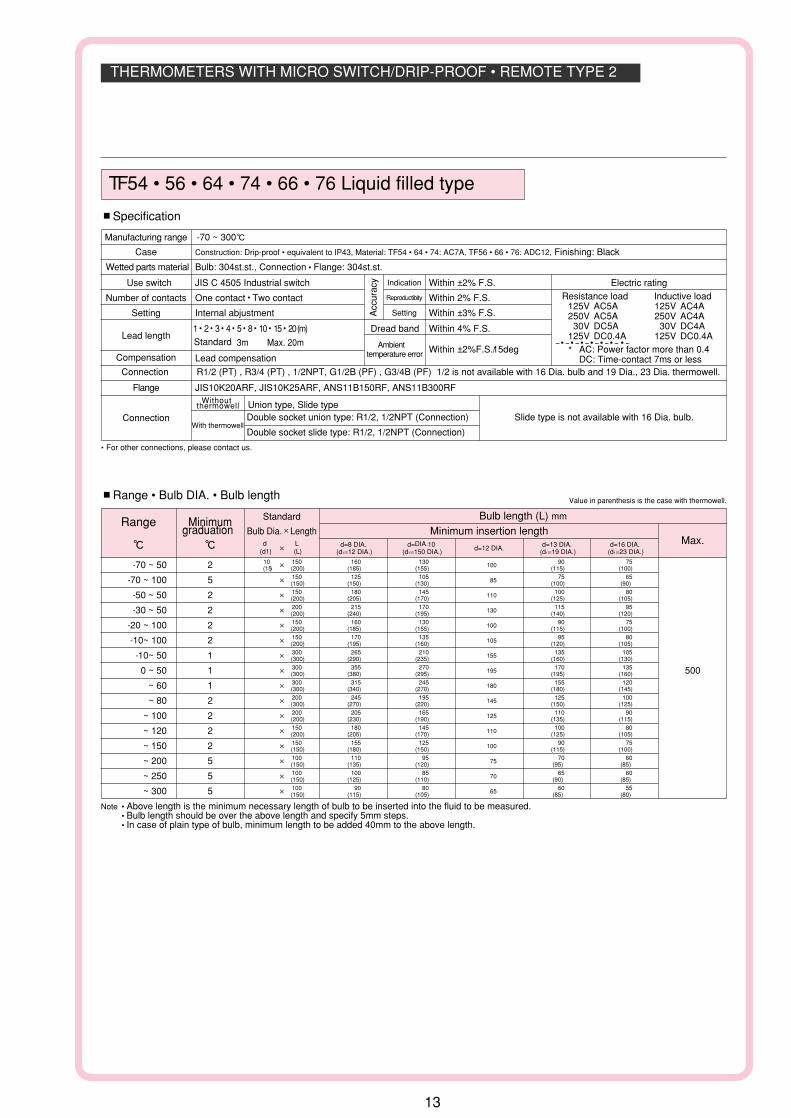
TF 54 • 56 • 64 • 74 • 66 • 76 Liquid filled type
#Specification
Manufacturing range -70 ~ 300g
Case Construction: Drip-proof • equivalent to IP43, Material: TF54 • 64 • 74: AC7A, TF56 • 66 • 76: ADC12, Finishing: Black
Wetted parts material Bulb: 304st.st., Connection • Flange: 304st.st.
Use switch JIS C 4505 Industrial switch
Acc
urac
y Indication Within ±2% F.S.
Reproductibity Within 2% F.S.
Setting Within ±3% F.S.
Number of contacts One contact • Two contact
Setting Internal abjustment
Lead length1 • 2 • 3 • 4 • 5 • 8 • 10 • 15 • 20 (m) Dread band Within 4% F.S.Standard 3m Max. 20m Ambient
temperature error Within ±2%F.S./15degCompensation Lead compensation
Connection R1/2 (PT) , R3/4 (PT) , 1/2NPT, G1/2B (PF) , G3/4B (PF) 1/2 is not available with 16 Dia. bulb and 19 Dia., 23 Dia. thermowell.
Flange JIS10K20ARF, JIS10K25ARF, ANS11B150RF, ANS11B300RFWithout
thermowell Union type, Slide type
With thermowellDouble socket union type: R1/2, 1/2NPT (Connection) Slide type is not available with 16 Dia. bulb.
Double socket slide type: R1/2, 1/2NPT (Connection)
* For other connections, please contact us.
Connection
Electric rating
#Range • Bulb DIA. • Bulb length
Range Minimumgraduation
g g
Standard
Bulb Dia.$Lengthd
(d1) L(L)
$
Bulb length (L) mm
Minimum insertion lengthMax.
500
d=8 DIA.(d1=12 DIA.)
d=DIA.10(d1=150 DIA.) d=12 DIA. d=13 DIA.
(d1=19 DIA.) d=16 DIA.
(d1=23 DIA.)
-70 ~ 50 2 $ 10010 150 160 130 90 75(15) (200) (185) (155) (115) (100)
-70 ~ 100 5 $ 85150 125 105 75 65(150) (150) (130) (100) (90)
-50 ~ 50 2 $ 110150 180 145 100 80(200) (205) (170) (125) (105)
-30 ~ 50 2 $ 130200 215 170 115 95(200) (240) (195) (140) (120)
-20 ~ 100 2 $ 100150 160 130 90 75(200) (185) (155) (115) (100)
-10~ 100 2 $ 105150 170 135 95 80(200) (195) (160) (120) (105)
-10~ 50 1 $ 155300 265 210 135 105(300) (290) (235) (160) (130)
0 ~ 50 1 $ 195300 355 270 170 135(300) (380) (295) (195) (160)
~ 60 1 $ 180300 315 245 155 120(300) (340) (270) (180) (145)
~ 80 2 $ 145200 245 195 125 100(300) (270) (220) (150) (125)
~ 100 2 $ 125200 205 165 110 90(200) (230) (190) (135) (115)
~ 120 2 $ 110150 180 145 100 80(200) (205) (170) (125) (105)
~ 150 2 $ 100150 155 125 90 75(150) (180) (150) (115) (100)
~ 200 5 $ 75100 110 95 70 60(150) (135) (120) (95) (85)
~ 250 5 $ 70100 100 85 65 60(150) (125) (110) (90) (85)
~ 300 5 $ 65100 90 80 60 55(150) (115) (105) (85) (80)
Note • Above length is the minimum necessary length of bulb to be inserted into the fluid to be measured.• Bulb length should be over the above length and specify 5mm steps.• In case of plain type of bulb, minimum length to be added 40mm to the above length.
Value in parenthesis is the case with thermowell.
Resistance load Inductive load125V AC5A 125V AC4A250V AC5A 250V AC4A30V DC5A 30V DC4A
125V DC0.4A 125V DC0.4A-• -• -• -• -• -• - • -
* AC: Power factor more than 0.4DC: Time-contact 7ms or less
13

THERMOMETERS WITH MICRO SWITCH/DRIP-PROOF • REMOTE TYPE3
3-5.5 DIA. Mounting hole
112
DIA
.
136
DIA
.
Setting positioning axis Gland JIS20b
(107) 76
4
30
62
P.C.D.122
#Dimension
3-5.5 DIA.Mounting hole
159
DIA
.
178
DIA
.
Setting positioning axis
Gland JIS20b
(159)
125
140
3
Armoredtube
P.C.D.165
#Dimension
3-5.5 DIA.Mounting hole
136
DIA
.
112
DIA
.
110
DIA
.
2-mounting clamp
Setting positioning axis
Gland JIS20b
76 (47)
21
4P.C.D.124
9
#Dimension
3-5.5DIA.Mounting hole
178
DIA
.
159
DIA
.
152
DIA
.
Gland JIS20b
Setting positioning axis
3-Mounting clamp
Armoredtube
129.5 61
26
3P.C.D.165
#Dimension
TE 54 • 100 DIA. • Surface mounting
TE 56 • 150 DIA. • Surface mounting
TE 64 • 74 • 100 DIA. • Panel mounting
TE 66 • 76 • 150 DIA. • Panel mounting
Mercury filled dial thermometer
Model Mounting
TE64 Mounting hole
TE74 Mounting clamp
Model Mounting
TE66 Mounting hole
TE76 Mounting clamp
14

THERMOMETERS WITH MICRO SWITCH/DRIP-PROOF • REMOTE TYPE 4
TE 54 • 56 • 64 • 74 • 66 • 76 Mercury filled dial thermometer
#Specification
Manufacturing range -50 ~ 650g
Case Construction: Drip-proof • equivalent to IP43, Material: TE54 • 64 • 74: AC7A, TE56 • 66 • 76: ADC12, Finishing: Black
Wetted parts material Bulb: 304st.st., Connection • Flange: 304st.st.
Use switch JIS C 4505 Industrial switch
Acc
urac
y Indication Within ±2% F.S.
Reproductibity Within 2% F.S.
Setting Within ±4% F.S.
Number of contacts 100 DIA.One contact, 150 DIA. One contact • Two contact
Setting Internal abjustment
Lead length1 • 2 • 3 • 4 • 5 • 8 • 10 (m) Dead band Within 8% F.S.Standard 3m Max. 10m Ambient
temprature error Within ±2% F.S./15degCompensation Bimetal compensation
Connection R1/2 (PT) , R3/4 (PT) , 1 /2NPT, G1/2B (PF) , G3/4B (PF) 1/2 is not available with 16 Dia. bulb and 19 Dia., 23 Dia. thermowell.
Flange JIS10K20ARF, JIS10K25ARF, ANS11B150RF, ANS11B300RFWithout
thermowell Union type, Slide type
Withthermowell
Double socket union type: R1/2, 1/2NPT (Connection) Slide type is not available with 16 Dia. bulb.
Double socket slide type: R1/2, 1/2NPT (Connection)
* For other connections, please contact us.
Connection
Electric rating
#Range • Bulb DIA. • Bulb length
Note • Above length is the minimum necessary length of bulb to be inserted into the fluid to be measured.• Bulb length should be over the above length and specify 5mm steps.• In case of plain type of bulb, minimum length to be added 40mm to the above length.
Value in parenthesis is the case with thermowell.
Range Minimum graduation
g g
Standard
Bulb Dia.$Length
With one contact With two contact
d(d1)
L(L)
$
Bulb length (L) mm
Minimum insertion lengthWith one contact With tne contact (Not available to 100mm Dia.) Max.
d=8 DIA., 16 DIA.
1000
d=10 DIA., 12 DIA.
13 13 DIA.
3000
d=8 DIA. d=10 DIA.(d1=12 DIA.) (d1=15 DIA.) d=12 DIA. d=13 DIA. d=16 DIA. d=8 DIA. d=10 DIA.
(d1=19 DIA.) (d1=23 DIA.) (d1=12 DIA.) (d1=15 DIA.) d=12 DIA. d=13 DIA. d=16 DIA.(d1=19 DIA.) (d1=23 DIA.)
-30 ~ 50 2 $ $ 215 - 29510 400 10 500 410 305 180 135 430 250 185(15) (400) (15) (500) (430) (325) (200) (155) (450) (270) (205)
-30 ~ 120 2 $ $ 115 170200 300 210 160 100 75 320 240 145 110(200) (300) (230) (180) (120) (95) (340) (260) (165) (130)
-20 ~ 100 2 $ $ 145 215200 400 265 200 120 90 410 305 180 135(300) (400) (285) (220) (140) (110) (430) (325) (200) (155)
-10~ 50 1 $ - - 270 - - 390400 390 225 170 330 240(500) (410) (245) (190) (350) (260)
0 ~ 50 1 - - - - 335 - - - -285 210 340(305) (230) (360)
~ 60 1 $ - - 270 - - 39010 400 390 225 170 330 240(15) (500) (410) (245) (190) (350) (260)
~ 80 2 $ $ 215 - 295400 10 500 410 305 180 135 430 250 185(400) (15) (500) (430) (325) (200) (155) (450) (270) (205)
~ 100 2 $ $ 170 - 250300 400 320 240 145 110 355 210 155(300) (400) (340) (260) (165) (130) (375) (230) (175)
~ 120 2 $ $ 145 215200 400 265 200 120 90 410 305 180 135(300) (400) (285) (220) (140) (110) (430) (325) (200) (155)
~ 150 2 $ $ 115 170200 300 210 160 100 75 320 240 145 110(200) (300) (230) (180) (120) (95) (340) (260) (165) (130)
~ 200 5 $ $ 95 130150 200 170 130 85 65 245 185 115 85(150) (300) (190) (150) (105) (85) (265) (205) (135) (105)
~ 250 5 $ $ 80 110150 150 135 105 70 55 200 150 95 70(150) (200) (155) (125) (90) (75) (220) (170) (115) (90)
~ 300 5 $ $ 70 85100 150 120 95 60 50 155 120 75 60(150) (150) (140) (115) (80) (70) (175) (140) (95) (80)
~ 400 10 $ $ 55 75100 100 90 75 50 40 125 100 65 50(100) (150) (110) (95) (70) (60) (145) (120) (85) (70)
~ 500 10 $ $ 50 60100 100 75 60 45 40 105 80 55 45(100) (100) (95) (80) (65) (60) (125) (100) (75) (65)
~ 600 10 $ $ 45 55
~ 650 20 $ $ 40 50
100 100 65 55 40 40 90 75 50 40(100) (100) (85) (75) (60) (60) (110) (95) (70) (60) 100 100 65 55 40 40 85 70 45 40(100) (100) (85) (75) (60) (60) (105) (90) (65) (60)
Resistance load Inductive load*125V AC5A 125V AC4A250V AC5A 250V AC4A30V DC5A 30V DC4A
125V DC0.4A 125V DC0.4A- • - • - • - • - • - • - • -
* AC: Power factor more than 0.4DC: Time-contact 7ms or less
15

EXPLOTION-PROOF THERMOMETER WITH MICRO SWITCH 1
Conduit type
Flame-proof packing type
175
15
105
115
214
DIA
.
221
40°40°
165
(16
0)80
25 (75)
62
157
4-10 DIA. Mounting hole
P.C.D.230
Setting positioningaxis
Terminal box
TD 25 Liquid filled dial thermometer
#Dimension
Applicable model d2G4Labor ministry inspection No. No.24201Weight Approx.12kg (Indicator part)
#Specification
Manufacturing range -70 ~ 300g
Indication dial With local indicator
Use switch JIS C 4505 Industrial switch
Number of contacts One contact, Two contact Dead band Within 4% F.S.
Acc
urac
y Indication Within ±2% F.S.
Reproductibity Within 2% F.S.
Setting Within ±3% F.S.
Setting External adjustment
Lead length1 • 2 • 3 • 4 • 5 • 8 • 10 • 15 • 20 (m)
Standard 3mMax. 20m
Case Construction: Drip-proof • equivalent to IP54, Material: AC7A, Finishing : Glay
Within ±2% F.S./15degAmbient
temperature error
Wetted parts Bulb: 304st.st., Connection • Flange: 304st.st.
Compensation Lead compensation
Connection R1/2 (PT) , R3/4 (PT) , 1/2NPT, G1/2B (PF) , G3/4B (PF) 1/2 is not available with 16 Dia. bulb and 19 Dia., 23 Dia. thermowell.
Flange JIS10K20ARF, JIS10K25ARF, ANSI1B150RF, ANSI1B300RFWithout
thermowell Union type, Slide type
Withthermowell
Double socket union type: R1/2, 1/2NPT (Connection) Slide type is not available with 16 Dia. bulb.
Double socket slide type: R1/2, 1/2NPT (Connection)
Connection
Electric rating
#Range • Bulb DIA. • Bulb length
Range Minimumgraduation
g g
Standard
Bulb Dia.$Lengthd
(d1) L(L)
$
Bulb length (L) mm
Minimum insertion lengthMax.
500
d=8 DIA.(d1=12 DIA.)
d=10 DIA.(d1=15 DIA.) d=12 DIA. d=13 DIA.
(d1=19 DIA.) d=16 DIA.
(d1=23 DIA.)
-70 ~ 50 2 $ 10010 150 160 130 90 75(15) (200) (185) (155) (115) (100)
-70 ~ 100 5 $ 85150 125 105 75 65(150) (150) (130) (100) (90)
-50 ~ 50 2 $ 110150 180 145 100 80(200) (205) (170) (125) (105)
-30 ~ 50 2 $ 130200 215 170 115 95(200) (240) (195) (140) (120)
-20 ~ 100 2 $ 100150 160 130 90 75(200) (185) (155) (115) (100)
-10~ 100 2 $ 105150 170 135 95 80(200) (195) (160) (120) (105)
-10~ 50 1 $ 155300 265 210 135 105(300) (290) (235) (160) (130)
0 ~ 50 1 $ 195300 355 270 170 135(300) (380) (295) (195) (160)
~ 60 1 $ 180300 315 245 155 120(300) (340) (270) (180) (145)
~ 80 2 $ 145200 245 195 125 100(300) (270) (220) (150) (125)
~ 100 2 $ 125200 205 165 110 90(200) (230) (190) (135) (115)
~ 120 2 $ 110150 180 145 100 80(200) (205) (170) (125) (105)
~ 150 2 $ 100150 155 125 90 75(150) (180) (150) (115) (100)
~ 200 5 $ 75100 110 95 70 60(150) (135) (120) (95) (85)
~ 250 5 $ 70100 100 85 65 60(150) (125) (110) (90) (85)
~ 300 5 $ 65100 90 80 60 55(150) (115) (105) (85) (80)
Note • Above length is the minimum necessary length of bulb to be inserted into the fluid to be measured.• Bulb length should be over the above length and specify 5mm steps.• In case of plain type of bulb, minimum length to be added 40mm to the above length.
Value in parenthesis is the case with thermowell.
Resistance load Inductive load
125V AC5A Power factor 0.75
250V AC5A Time-contact 7ms or less
30V DC5A 125V AC4A125V DC0.4A 250V AC4A
30V DC4A125V DC0.4A
( )
16

EXPLOTION-PROOF THERMOMETER WITH MICRO SWITCH 2
175
15
105
115
221
40° 40° 4-10 DIA. Mounting hole
P.C.D. 230
214D
IA.
165
(16
0)
(15
7)
Terminal box
Flame-proof packing type
Conduit type
TD 21 Mercury filled dial thermometer
#Dimension
Applicable model d2G4Labor ministry inspection No. No.24200Weight Approx11.5kg(Indicator part)
#Specification
Manufacturing range -50 ~ 650g
Indication dial With local indicator
Use switch JIS C 4505 Industrial switch
Number of contacts One contact, Two contact Dead band Within 8%F.S.
Acc
urac
y Indication Within ±2%F.S.
Reproductibity Within 2%F.S.
Setting Within ±4%F.S.
Setting Internal adjustment
Lead length1 • 2 • 3 • 4 • 5 • 8 • 10 (m) standard 3m
Max. 10m
case Construction: Drip-proof • equivalent to IP54, Material: AC7A, Finishing : Glay
Within ±2%F.S./15degAmbient
temperature error
Wetted parts Bulb: 304st.st., Connection • Flange: 304st.st.
Compensation Bimetal compensation
Connection R1/2 (PT) , R3/4 (PT) , 1/2NPT, G1/2B (PF) , G3/4B (PF) 1/2 is not available with 16 Dia. bulb and 19 Dia., 23 Dia. thermowell.
Flange JIS10K20ARF, JIS10K25ARF, ANSI1B150RF, ANSI1B300RFWithout
thermowell Union type, Slide type
Withthermowell
Double socket union type: R1/2, 1/2NPT (Connection) Slide type is not available with 16 Dia. bulb.
Double socket slide type: R1/2, 1/2NPT (Connection)
Connection
Electric rating
Resistance load Inductive load
125V AC5A Power factor 0.75
250V AC5A Time-contact 7ms or less
30V DC5A 125V AC4A125V CD0.4A 250V AC4A
30V DC4A125V DC0.4A
( )
#Range • Bulb DIA. • Bulb length
Range Minimum graduation
g g
standard
Bulb Dia.$Length
With one contact With two contact
d(d1)
L(L)
$
Bulb length (L) mm
Minimum insertion lengthWith one contact With tne contact Max.
d=8 DIA., 16 DIA.,
1000
d=10 DIA., 12 DIA.,
d=8 DIA. d=10 DIA.(d1=12 DIA.) (d1=15 DIA.) d=12 DIA. d=13 DIA. d=16 DIA. d=8 DIA. d=10 DIA.
(d1=19 DIA.) (d1=23 DIA.) (d1=12 DIA.) (d1=15 DIA.) d=12 DIA. d=13 DIA. d=16 DIA.(d1=19 DIA.) (d1=23 DIA.)
-30 ~ 50 2 $ $ 215 - 29510 400 10 500 410 305 180 135 430 250 185(15) (400) (15) (500) (430) (325) (200) (155) (450) (270) (205)
-30 ~ 120 2 $ $ 115 170200 300 210 160 100 75 320 240 145 110(200) (300) (230) (180) (120) (95) (340) (260) (165) (130)
-20 ~ 100 2 $ $ 145 215200 400 265 200 120 90 410 305 180 135(300) (400) (285) (220) (140) (110) (430) (325) (200) (155)
-10~ 50 1 $ - - 270 - - 390400 390 225 170 330 240(500) (410) (245) (190) (350) (260)
0 ~ 50 1 - - - - 335 - - - -285 210 340(305) (230) (360)
~ 60 1 $ - - 270 - - 39010 400 390 225 170 330 240(15) (500) (410) (245) (190) (350) (260)
~ 80 2 $ $ 215 - 295400 10 500 410 305 180 135 430 250 185(400) (15) (500) (430) (325) (200) (155) (450) (270) (205)
~ 100 2 $ $ 170 - 250300 400 320 240 145 110 355 210 155(300) (400) (340) (260) (165) (130) (375) (230) (175)
~ 120 2 $ $ 145 215200 400 265 200 120 90 410 305 180 135(300) (400) (285) (220) (140) (110) (430) (325) (200) (155)
~ 150 2 $ $ 115 170200 300 210 160 100 75 320 240 145 110(200) (300) (230) (180) (120) (95) (340) (260) (165) (130)
~ 200 5 $ $ 95 130150 200 170 130 85 65 245 185 115 85(150) (300) (190) (150) (105) (85) (265) (205) (135) (105)
~ 250 5 $ $ 80 110150 150 135 105 70 55 200 150 95 70(150) (200) (155) (125) (90) (75) (220) (170) (115) (90)
~ 300 5 $ $ 70 85100 150 120 95 60 50 155 120 75 60(150) (150) (140) (115) (80) (70) (175) (140) (95) (80)
~ 400 10 $ $ 55 75100 100 90 75 50 40 125 100 65 50(100) (150) (110) (95) (70) (60) (145) (120) (85) (70)
~ 500 10 $ $ 50 60150 100 75 60 45 40 105 80 55 45(150) (100) (95) (80) (65) (60) (125) (100) (75) (65)
~ 600 10 $ $ 45 55
~ 650 20 $ $ 40 50
150 100 65 55 40 40 90 75 50 40(150) (100) (85) (75) (60) (60) (110) (95) (70) (60) 150 100 65 55 40 40 85 70 45 40(150) (100) (85) (75) (60) (60) (105) (90) (65) (60)
Note • Above length is the minimum necessary length of bulb to be inserted into the fluid to be measured.• Bulb length should be over the above length and specify 5mm steps.• In case of plain type of bulb, minimum length to be added 40mm to the above length.
Value in parenthesis is the case with thermowell.
17
13 DIA.3000

THRMOMETER WITH MICRO SWITCH FOR TRANSFORMER 1
D4-7 DIA. Mounting hole
P.C.D. D3
D
h
b
w
Setting positioning axis
TX 54 • 56 Mercury filled dial thermometer • Waterproof and moisture resistance type
#Specification
Manufacturing range -30 ~ 650g
Use switch JIS C 4505 Industrial switch
Number of contacts One contact, Two contact
Setting Internal adjustment Dead band Within 8% F.S.
Acc
urac
y Indication Within ±2% F.S.
Reproductibity Within 2% F.S.
Setting Within ±4% F.S.
Max. pointer Option
Max.lead length 5m (standard 3m)
case Construction: Water-proof • equivalent to IP65 , Material: Alminium alloy, Finishing: Black
Within ±2% F.S./ 15degAmbient
temperature error
Wetted parts Bulb: 304st.st., Connection • Flange: 304st.st.
Compensation Bimetal compensation
Connection R1/2 (PT) , R3/4 (PT) , 1 /2NPT, G1/2B (PF) , G3/4B (PF) 1/2 is not available with 16 Dia. bulb and 19 Dia., 23 Dia. thermowell.
Flange JIS10K20ARF, JIS10K25ARF, ANSI1B150RF, ANSI1B300RFWithout
thermowell Union type, Slide type
Withthermowell
Double socket union type: R1/2, 1/2NPT (Connection) Slide type is not available with 16 Dia. bulb.
Double socket slide type: R1/2, 1/2NPT (Connection)
Connection
Electric rating
Resistance load250V AC3A 125V DC0.4AInductive load2000V AC1 minuteInsulation resistanceIt is more than 500V DC 100MΩ with megger
#Range • Bulb DIA. • Bulb length Value in parenthesis is the case with thermowell.
Range Minimumgraduation
g g
Bulb length (L) mm
Minimum insertion lengthMax.
d=8 DIA., 16 DIA.1000
d=10 DIA., 12 DIA.,13 DIA.
3000
d=8 DIA.(d1=12 DIA.)
d=10 DIA.(d1=15 DIA.) d=12 DIA. d=13 DIA.
(d1=19 DIA.) d=16 DIA.
(d1=23 DIA.)
-30 ~ 120 2 120 (140) 95 (115) 70 60 (80) 50 (70)
-20 ~ 100 2 150 (170) 120 (140) 85 75 (95) 60 (80)
0 ~ 100 2 180 (200) 140 (160) 100 85 (105) 65 (85)
~ 120 2 150 (170) 120 (140) 85 75 (95) 60 (80)
~ 150 2 120 (140) 95 (115) 70 60 (80) 50 (70)
~ 200 5 100 (120) 80 (100) 60 55 (75) 45 (65)
~ 300 5 70 (90) 60 (80) 45 40 (60) 40 (60)
~ 500 10 55 (75) 45 (65) 40 40 (60) 40 (60)
~ 650 20 45 (65) 40 (60) 40 40 (60) 40 (60)
Note • Above length is the minimum necessary length of bulb to be inserted into the fluid to be measured.• Bulb length should be over the above length and specify 5mm steps.• In case of plain type of bulb, minimum length to be added 40mm to the above length.
Model Dial size
TX54 100 125 126 87.5 4 112.5
Dimension
D D3 b W h
TX54 • 100 DIA.
4-10 DIA. Mounting hole
Setting positioning axis
b
a
D D
IA.
w
n
Armored tube
P.C.D.D3
Model Dial size
TX56 150 188 180 23 90 7 215
Dimension
D D3 a b W h
TX56 • 150 DIA.
18

THRMOMETER WITH MICRO SWITCH FOR TRANSFORMER2
E
h
b
a
w
E1
D D
IA.
Setting pointer
4-10 DIA.Mounting hole
Setting positioning axis
Armored tube
TX 81 Liquid filled dial thermometer • Waterproof and moisture resistance type
#Dimension
#Specification
Manufacturing range -70 ~ 300g
Use switch JIS C 4505 Industrial switch
Number of contacts One contact ~ Four contact
Setting Internal adjustment Dead band Within 7% F.S.
Acc
urac
y Indication Within ±2% F.S.
Reproductibity Within 2% F.S.
Setting Within ±4% F.S.
Max. pointer Standard
Max.lead length 20m (standard 3m)
Cace Construction: Water-proof • equivalent to IP65, Material: Alminium alloy, Finishing: Black
Within ±2% F.S./ 15degAmbient
temperature error
Wetted parts Bulb: 304st.st., Connection • Flange: 304st.st.
Compensation Lead compensation
Connection R1/2 (PT) , R3/4 (PT) , 1/2NPT, G1/2B (PF) , G3/4B (PF) 1/2 is not available with 16 Dia. bulb and 19 Dia., 23 Dia. thermowell.
Flange JIS10K20ARF, JIS10K25ARF, ANSI1B150R, ANSI1B300RFWithout
thermowell Union type, Slide type
Withthermowell
Double socket union type: R1/2, 1/2NPT (Connection) Slide type is not available with 16 Dia. bulb.
Double socket slide type: R1/2, 1/2NPT (Connection)
Connection
Electric rating
Resistance load
250V AC10A 125V DC0.6AInductive load
2000v AC 1minuteInsulation resistanceIt is more than 500V DC 100MΩ with megger
#Range • Bulb DIA. • Bulb length Value in parenthesis is the case with thermowell.
Range Minimumgraduation
g g
Bulb length (L) mm
Minimum insertion lengthMax.
500
d=8 DIA.(d1=12 DIA.)
d=10 DIA.(d1=15 DIA.) d=12 DIA. d=13 DIA.
(d1=19 DIA.) d=16 DIA.
(d1=23 DIA.)
-70 ~ 100 5 125 (150) 105 (130) 85 75 (100) 65 (90)
-50 ~ 50 2 180 (205) 145 (170) 110 100 (125) 80 (105)
-20 ~ 100 2 160 (185) 130 (155) 100 90 (115) 75 (100)
0 ~ 50 1 355 (380) 270 (295) 195 170 (195) 135 (160)
~ 100 2 205 (230) 165 (190) 125 110 (135) 90 (115)
~ 120 2 180 (205) 145 (170) 110 100 (125) 80 (105)
~ 150 2 155 (180) 125 (150) 100 90 (115) 75 (100)
~ 200 5 110 (135) 95 (120) 75 70 (95) 60 (85)
~ 300 5 90 (115) 80 (105) 65 60 (85) 55 (80)
Note • Above length is the minimum necessary length of bulb to be inserted into the fluid to be measured.• Bulb length should be over the above length and specify 5mm steps.• In case of plain type of bulb, minimum length to be added 40mm to the above length.
Model Dial size
TX81 150 188 127 152 23 105 7 206
Dimension
D E E1 a b W h
19

THERMOMETER WITH CONTACT SWITCH /INDOOR • REMOTE TYPE1
Stiing pointer
3-5.5DIA. Mounting hple
P.C.D. D3
b
w
D D
IA.
D1 D
IA.
Setting positioning axis
Gasket bore 9 DIA.
c
#Dimension
Setting pointer
3-5.5DIA. Mounting hole
P.C.D. D3Setting positioning axis
b
a
w
D1
DIA
.
D D
IA.
D4 D
IA.
(46)
Gasket bore. 9 DIA.
#Dimension
Setting pointer
Setting pointer
Settting positioninf axis
b
a
(46)
Gasket bore. 9 DIA.
D D
IA.
D4 D
IA.
#Dimension
TK 54 • 56 Liquid filled dial thermometer • TJ 54 • 56 Mercury filled dial thermometer
TK 64 • 66 Liquid filled dial thermometer • TJ 64 • 66 Mercury filled dial thermometer
TK 74 • 76 Liquid filled dial thermometer • TJ 74 • 76 Mercury filled dial thermometer
Surface mounting
Panel mounting(Mounting hole )
Panel mounting(Mounting clamp)
#SpecificationManufacturing range TK 53 • 70 ~ 500g TJ 53 • ~ 650g
Use switch Contact switch (Open type low contact)
Number of contacts One contact, Two contact
Setting External adjustment Dead band Within ±4% F.S.
Acc
urac
y Indication Within ±2% F.S.
Reproductibity Within 2% F.S.
Setting Within ±3% F.S.
TK33
1 • 2 • 3 • 4 • 5 • 8 • 10 • 15 • 20 (m) Standard 3mBimetal compenstion 5m max.(350g or over 30m) Lead compenstion 20m max.Lead length1 • 2 • 3 • 4 • 5 • 8 • 10 • 15 • 20 (m) Standard 3 mBimetal compenstion 20 m max.Lead compenstion 50 m max.
TJ33
Within ±2% F.S./ 15deg
TJ34, TK34 Bimetal compenstion
TJ36, TK36 Bimetal compenstion • Lead compenstion
In case of more than 350g only bimetal compensation type.
Ambient
temperature error
Compenstion
Case Construction: Indoor use • equivalent to IP32, T354: ADC12, Others: AC7A, Finishing: Black
Wetted parts Bulb: 304st.st., Connection • Flange: 304st.st.
Connection R1/2 (PT) , R3/4 (PT) , 1/2NPT, G1/2B (PF) , G3/4B ([F) 1/2 is not available with 16 Dia. bulb and 19 Dia., 23 Dia. thermowell.
Flange JIS10K20ARF, JIS10K25ARF, ANSI1B150RF, ANSI1B300RFWithout
thermowell Union type, Slide type
Withthermowell
Double socket union type: R1/2, 1/2NPT (Connection) Slide type is not available with 16 Dia. bulb.
Double socket slide type: R1/2,1/2NPT (Connection)
Connection
Electric rating
Resistance load100V AC0.5A200V AC0.25A100V DC0.05A200V DC0.025A
Model Dial size
TJ54TK54 100 112 128 115 78 3 (111)
TJ56TK56 150 165 178 165 85 4 (137)
DimensionD D1 D3 b W C
Model Dial size
TJ64 • TJ74TK64 • TK74 100 112 136 122 104 19 79 3
TJ66 • TJ76TK66 • TK76 150 165 192 178 158 21 85 4
DimensionD D1 D3 D4 a b W
20

THERMOMETER WITH CONTACT SWITCH/INDOOR • REMOTE TYPE2
#Range • Bulb DIA. • Bulb length
TK 5 • 6 • 7 (Liquid filled dial thermometer • With contact switch)
Range Minimumgraduation
g g
StandardBulb Dia.$Length
d(d1)
L(L)
$
Bulb length (L) mm
Minimum insertion lengthMax.
500
d=8 DIA., 16 DIA. 1000
d=10 DIA., 12 DIA., 13 DIA.3000
d=8 DIA.(d1=12 DIA.)
d=10 DIA.(d1=15 DIA.) d=12 DIA. d=13 DIA.
(d1=19 DIA.) d=16 DIA.
(d1=23 DIA.)
-70 ~ 50 2 $ 4010 100 50 45 40 50(15) (100) (75) (70) (65) (75)
-70 ~ 100 5 $ 40100 40 40 40 40(100) (65) (65) (65) (65)
-50 ~ 50 2 $ 40100 55 45 40 55(100) (80) (70) (65) (80)
-30 ~ 50 2 $ 45100 65 55 40 40(100) (90) (80) (65) (65)
-20 ~ 100 2 $ 40100 50 45 40 50(100) (75) (70) (65) (75)
-10 ~ 50 1 $ 50100 70 60 45 40(100) (95) (85) (70) (65)
0 ~ 50 1 $ 60100 95 75 50 45(100) (120) (100) (75) (70)
~ 60 1 $ 50100 70 60 45 40(100) (95) (85) (70) (65)
~ 80 2 $ 45100 65 55 40 40(100) (90) (80) (65) (65)
~ 100 2 $ 40100 55 45 40 55(100) (80) (70) (65) (80)
~ 120 2 $ 40100 50 45 40 50(100) (75) (70) (65) (75)
~ 150 2 $ 40100 40 40 40 40(100) (65) (65) (65) (65)
~ 200 5 $ 40100 40 40 40 40(100) (65) (65) (65) (65)
~ 250 5 $ 40100 40 40 40 40(100) (65) (65) (65) (65)
~ 300 5 $ 40100 40 40 40 40(100) (65) (65) (65) (65)
~ 400 10 $ 120
~ 500 10 $ 120
200 230 170 100 80(200) (255) (195) (125) (105) 200 230 170 100 80(200) (255) (195) (125) (105)
Value in parenthesis is the case with thermowell.
TJ 5 • 6 • 7 (Mercury filled dial thermometer • With contact switch)
Range Minimumgraduation
g g
StandardBulb Dia.$Length
d(d1)
L(L)
$
Bulb length (L) mm
Minimum insertion lengthMax.
d=8 DIA., 16 DIA. 1000
d=10 DIA., 12 DIA., 13 DIA.
3000
d=8(d1=12 DIA.)
d=10 DIA.(d1=15 DIA.) d=12 DIA. d=13 DIA.
(d1=19 DIA.) d=16 DIA.
(d1=23 DIA.)
-30 ~ 50 2 $ 11510 200 210 160 100 75(15) (200) (230) (180) (120) (95)
-30 ~ 120 2 $ 70100 120 95 60 50(150) (140) (115) (80) (70)
-20 ~ 100 2 $ 80200 145 110 70 55(200) (165) (130) (90) (75)
-10 ~ 50 1 $ 155300 290 220 130 100(300) (310) (240) (150) (120)
0 ~ 50 1 $ 190300 360 270 160 120(300) (380) (290) (180) (140)
~ 60 1 $ 155300 290 220 130 100(300) (310) (240) (150) (120)
~ 80 2 $ 115200 210 160 100 75(200) (230) (180) (120) (95)
~ 100 2 $ 95200 170 130 85 65(200) (190) (150) (105) (85)
~ 120 2 $ 80200 145 110 70 55(200) (165) (130) (90) (75)
~ 150 2 $ 70100 120 95 60 50(150) (140) (115) (80) (70)
~ 200 5 $ 55100 90 75 50 40(100) (110) (95) (70) (60)
~ 250 5 $ 50100 75 60 45 40(100) (95) (80) (65) (60)
~ 300 5 $ 45100 70 60 40 40(100) (90) (80) (60) (60)
~ 400 10 $ 40100 60 50 40 40(100) (80) (70) (60) (60)
~ 500 10 $ 40100 50 40 40 40(100) (70) (60) (60) (60)
~ 600 10 $ 40
~ 650 20 $ 40
100 45 40 40 40(100) (65) (60) (60) (60) 100 45 40 40 40(100) (65) (60) (60) (60)
Value in parenthesis is the case with thermowell.
Note • Above length is the minimum necessary length of bulb to be inserted into the fluid to be measured.• Bulb length should be over the above length and specify 5mm steps.• In case of plain type of bulb, minimum length to be added 40mm to the above length.
21

EXPLOTION-PROOF THERMOMETER WITH CONTACT SWITCH 1
175
15
105
115
214
DIA
.
Terminal box 221
4-10 DIA. Mounting hole
P.C.D. 230
(15
7)
165
40° 40°
(16
0)
Flame-proof packing type
Conduit type
80
TD 10 Liquid filled dial thermometer
$Dimension
Applicable model d2G4Labor ministry inspection No. No.24199(TD11Model applied product)
Weight Approx.11kg (Indicator part)
#Specification
Manufacturing range -70 ~ 500g
Indication dial With local indicator
Use switch Contact switch (Open type low contact)
Number of contacts One contact, Two contact Dead band Within 4% F.S.
Acc
urac
y Indication Within ±2% F.S.
Reproductibity Within 2% F.S.
Setting Within ±3% F.S.
Setting Internal adjustment
Lead length1 • 2 • 3 • 4 • 5 (m) Standard 3m
Max. 5m, 350g or over. 30m
Case Construction : Drip-proof • equivalent to IP54, Material:AC7A, Finishing :Glay
Within ±2% F.S./15degAmbient
temperature error
Wetted parts Bulb:304st.st., Connection • Flange:304st.st.
Compensation Bimetal compensation
Connection R1/2 (PT), R3/4 (PT), 1/2NPT, G1/2B (PF), G3/4B (PF) 1/2 is not available with 16 Dia. bulb and 19 Dia., 23 Dia. thermowell.
Flange JIS10K20ARF, JIS10K25ARF, ANSI1B150RF, ANSI1B300RFWithout
thermowell Union type, Slide type
Withthermowell
Double socket union type:R1/2,1/2NPT (Connection) Slide type is not available with 16 Dia. bulb.
Double socket slide type:R1/2,1/2NPT (Connection)
Connection
Electric rating
Resistance load
100V AC0.5A
200V AC0.25A
100V DC0.05A
200V DC0.025A
#Range • Bulb DIA. • Bulb length
Range Minimumgraduation
g g
Standard
Bulb Dia.$Lengthd
(d1)L(L)
$
Bulb length (L)mm
Minimum insertion lengthMax.
500
d=8 DIA., 16 DIA. 1000
d=10 DIA., 12 DIA., 13 DIA.3000
d=8 DIA.(d1=12 DIA.)
d=10 DIA.(d1=15 DIA.) d=12 DIA. d=13 DIA.
(d1=19 DIA.)d=16 DIA.
(d1=23 DIA.)
-70 ~ 50 2 $ 4010 100 50 45 40 50(15) (100) (75) (70) (65) (75)
-70 ~ 100 5 $ 40100 40 40 40 40(100) (65) (65) (65) (65)
-50 ~ 50 2 $ 40100 55 45 40 55(100) (80) (70) (65) (80)
-30 ~ 50 2 $ 45100 65 55 40 40(100) (90) (80) (65) (65)
-20 ~ 100 2 $ 40100 50 45 40 50(100) (75) (70) (65) (75)
-10 ~ 50 1 $ 50100 70 60 45 40(100) (95) (85) (70) (65)
0 ~ 50 1 $ 60100 95 75 50 45(100) (120) (100) (75) (70)
~ 60 1 $ 50100 70 60 45 40(100) (95) (85) (70) (65)
~ 80 2 $ 45100 65 55 40 40(100) (90) (80) (65) (65)
~ 100 2 $ 40100 55 45 40 55(100) (80) (70) (65) (80)
~ 120 2 $ 40100 50 45 40 50(100) (75) (70) (65) (75)
~ 150 2 $ 40100 40 40 40 40(100) (65) (65) (65) (65)
~ 200 5 $ 40100 40 40 40 40(100) (65) (65) (65) (65)
~ 250 5 $ 40100 40 40 40 40(100) (65) (65) (65) (65)
~ 300 5 $ 40100 40 40 40 40(100) (65) (65) (65) (65)
~ 400 10 $ 120
~ 500 10 $ 120
200 230 170 100 80(200) (255) (195) (125) (105)200 230 170 100 80(200) (255) (195) (125) (105)
Value in parenthesis is the case with thermowell.
Note • Above length is the minimum necessary length of bulb to be inserted into the fluid to be measured.• Bulb length should be over the above length and specify 5mm steps.• In case of plain type of bulb, minimum length to be added 40mm to the above length.
22
EXPLOTION-PROOF THERMOMETER WITH CONTACT SWITCH 2
175
15
214
DIA
.
105
115
221
165
(15
7)
(16
0)
Terminal box
4-10 DIA. Mounting hole
P.C.D. 23040° 40°
Flame-proof packing type
Conduit type
80
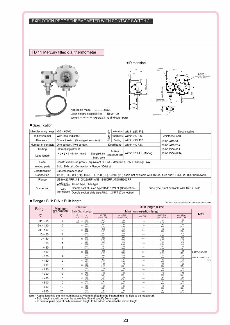
TD 11 Mercury filled dial thermometer
#Dimension
Applicable model d2G4Labor ministry inspection No. No.24199Weight Approx.11kg (Indicator part)
#Specification
Manufacturing range -50 ~ 650g
Indication dial With local indicator
Use switch Contact switch (Open type low contact)
Number of contacts One contact, Two contact Dead band Within 4% F.S.
Acc
urac
y Indication Within ±2% F.S.
Reproductibity Within 2% F.S.
Setting Within ±3% F.S.
Setting Internal adjustment
Lead length1 • 2 • 3 • 4 • 5 • 8 • 10 (m) Standard 3m
Max. 20m
Case Construction: Drip-proof • equivalent to IP54 , Material: AC7A, Finishing: Glay
Within ±2% F.S./15degAmbient
temperature error
Wetted parts Bulb: 304st.st., Connection • Flange: 304st.st.
Compensation Bimetal compensation
Connection R1/2 (PT), R3/4 (PT), 1/2NPT, G1/2B (PF), G3/4B (PF) 1/2 is not available with 16 Dia. bulb and 19 Dia., 23 Dia. thermowell.
Flange JIS10K20ARF, JIS10K25ARF, ANSI1B150RF, ANSI1B300RFWithout
thermowell Union type, Slide type
Withthermowell
Double socket union type:R1/2, 1/2NPT (Connection) Slide type is not available with 16 Dia. bulb.
Double socket slide type:R1/2, 1/2NPT (Connection)
Connection
Electric rating
Resistance load
100V AC0.5A
200V AC0.25A
100V DC0.05A
200V DC0.025A
#Range • Bulb DIA. • Bulb length Value in parenthesis is the case with thermowell.
Range Minimumgraduation
g g
Standard
Bulb Dia.$Lengthd
(d1)L(L)
$
Bulb length (L)mm
Minimum insertion lengthMax.
d= 8 DIA., 16 DIA. 1000
d=10 DIA., 12 DIA., 13 DIA.
3000
d=8 DIA.(d1=12 DIA.)
d=10 DIA.(d1=15 DIA.) d=12 DIA. d=13 DIA.
(d1=19 DIA.)d=16 DIA.
(d1=23 DIA.)
-30 ~ 50 2 $ 11510 200 210 160 100 75(15) (200) (230) (180) (120) (95)
-30 ~ 120 2 $ 70100 120 95 60 50(150) (140) (115) (80) (70)
-20 ~ 100 2 $ 80200 145 110 70 55(200) (165) (130) (90) (75)
-10 ~ 50 1 $ 155300 290 220 130 100(300) (310) (240) (150) (120)
0 ~ 50 1 $ 190300 360 270 160 120(300) (380) (290) (180) (140)
~ 60 1 $ 155300 290 220 130 100(300) (310) (240) (150) (120)
~ 80 2 $ 115200 210 160 100 75(200) (230) (180) (120) (95)
~ 100 2 $ 95200 170 130 85 65(200) (190) (150) (105) (85)
~ 120 2 $ 80200 145 110 70 55(200) (165) (130) (90) (75)
~ 150 2 $ 70100 120 95 60 50(150) (140) (115) (80) (70)
~ 200 5 $ 55100 90 75 50 40(100) (110) (95) (70) (60)
~ 250 5 $ 50100 75 60 45 40(100) (95) (80) (65) (60)
~ 300 5 $ 45100 70 60 40 40(100) (90) (80) (60) (60)
~ 400 10 $ 40100 60 50 40 40(100) (80) (70) (60) (60)
~ 500 10 $ 40100 50 40 40 40(100) (70) (60) (60) (60)
~ 600 10 $ 40
~ 650 20 $ 40
100 45 40 40 40(100) (65) (60) (60) (60)100 45 40 40 40(100) (65) (60) (60) (60)
Note • Above length is the minimum necessary length of bulb to be inserted into the fluid to be measured.• Bulb length should be over the above length and specify 5mm steps.• In case of plain type of bulb, minimum length to be added 40mm to the above length.
23

THRMOMETER WITH CONTACT SWITCH FOR TRANSFORMER 1
b
w
3-5.5 DIA. Mounting hole
Setting pointer
Setting positionaxis
D D
IA.
D1 D
IA.
Armoredtube
P.C.D. D3
TW 84 Liquid filled dial thermometer • Indoor use
#Dimension
#Specification
Manufacturing range -70 ~ 500g
Use switch Contact switch (Open type low contact)
Number of contacts One contact
Setting Internal adjustment Dead band Within 7% F.S.
Acc
urac
y Indication Within ±2% F.S.
Reproductibity Within 2% F.S.
Setting Within ±4% F.S.
Max. pointer Option
Max. lead length 5m (Standard 3m)
Case Construction: Indoor use • equivalent to IP43, Material: Alminium alloy, Finishing: Black
Within ±2% F.S./15degAmbient
temperature error
Wetted parts Bulb: 304st.st., Connection • Flange: 304st.st.
Compensation Bimetal compensation
Connection R1/2 (PT), R3/4 (PT), 1/2NPT, G1/2B (PF), G3/4B (PF) 1/2 is not available with 16 Dia. bulb and 19 Dia., 23 Dia. thermowell.
Flange JIS10K20ARF, JIS10K25ARF, ANSI1B150RF, ANSI1B300RFWithout
thermowell Union type, Slide type
Withthermowell
Double socket union type: R1/2, 1/2NPT (Connection) Slide type is not available with 16 Dia. bulb.
Double socket slide type:R1/2, 1/2NPT (Connection)
• Apply the contact contactor in normal open condition.• In the case of 2 contact point type, as a common pole exists, independent 2 circuits are not obtained.
* 2000V AC 1minute for transformer application.
Connection
Electric rating
Resistance load200V AC 0.25A 200V DC 0.025AWithstand voltage* 1000V AC 1minuteInsulation resistanceIt is more than 500V DC 100MΩ with megger
#Range • Bulb DIA. • Bulb lengthValue in parenthesis is the case with thermowell.
Range Minimumgraduation
g g
Bulb length (L) mm
Minimum insertion lengthMax.
500
d=8 DIA.,16 DIA. 1000d=10 DIA.,12 DIA.,13 DIA. 3000
d=8 DIA.(d1=12 DIA.)
d=10 DIA.(d1=15 DIA.) d=12 DIA. d=13 DIA.
(d1=19 DIA.)d=16 DIA.
(d1=23 DIA.)
-70 ~ 100 5 40 (65) 40 (65) 40 40 (65) 40 (65)
-20 ~ 100 2 50 (75) 45 (70) 40 40 (65) 50 (75)
0 ~ 50 1 95 (120) 75 (100) 60 50 (75) 45 (70)
~ 100 2 55 (80) 45 (70) 40 40 (65) 55 (80)
~ 120 2 50 (75) 45 (70) 40 40 (65) 50 (75)
~ 150 2 40 (65) 40 (65) 40 40 (65) 40 (65)
~ 200 5 40 (65) 40 (65) 40 40 (65) 40 (65)
~ 300 5 40 (65) 40 (65) 40 40 (65) 40 (65)
~ 500 10 230 (255) 170 (195) 120 100 (125) 80 (105)
Note • Above length is the minimum necessary length of bulb to be inserted into the fluid to be measured.• Bulb length should be over the above length and specify 5mm steps.• In case of plain type of bulb, minimum length to be added 40mm to the above length.
* Models of which temperature sensing portio
is partially flat can be mounfactured.
Model Dial size
TW84 100 112 134 124 78 3.5
Dimension
D D1 D3 b W
24

THRMOMETER WITH CONTACT SWITCH FOR TRANSFORMER 2
b
w
4-7 DIA. Mounting hole
Setting pointer
D
P.C.D. D3
h
Armoredtube
TW 54 Liquid filled dial thermometer • Waterproof and moisture resistance type
#Dimension
#Specification
Manufacturing range -70 ~ 500g
Use switch Contact switch (Open type low contact)
Number of contacts One contactf • Two contact
Setting Internal adjustment Dead band Within 7% F.S.
Acc
urac
y Indication Within ±2% F.S.
Reproductibity Within 2% F.S
Setting Within ±4% F.S.
Max. pointer Option
Max. lead length 5m (Standard 3m)
Case Construction: Water-proof • equivalent to IP65, Material: Alminium alloy, Finishing: Black
Within ±2% F.S./15degAmbient
temperature error
Wetted parts Bulb: 304st.st., Connection • Flange: 304st.st.
Compensation Bimetal compensation
Connection R1/2 (PT), R3/4 (PT), 1/2NPT, G1/2B (PF), G3/4B (PF) 1/2 is not available with 16 Dia. bulb and 19 Dia., 23 Dia. thermowell.
Flange JIS10K20ARF, JIS10K25ARF, ANSI1B150RF, ANSI1B300RFWithout
thermowell Union type, Slide type
Withthermowell
Double socket union type:R1/2, 1/2NPT (Connection) Slide type is not available with 16 Dia. bulb.
Double socket slide type:R1/2, 1/2NPT (Connection)
• Apply the contact contactor in normal open condition.• In the case of 2 contact point type, as a common pole exists, independent 2 circuits are not obtained.
* 2000V AC 1minute for transformer application.
Connection
Electric rating
Resistance load200V AC 0.25A 200V DC 0.025AWithstand voltage* 1000V AC 1minuteInsulation resistanceIt is more than 500V DC 100MΩ with megger
#Range • Bulb DIA. • Bulb length Value in parenthesis is the case with thermowell.
Range Minimumgraduation
g g
Bulb length (L)mm
Minimum insertion lengthMax.
500
d=8 DIA., 16 DIA. 1000d=10 DIA., 12 DIA., 13 DIA.3000
d=8 DIA.(d1=12 DIA.)
d=10 DIA.(d1=15 DIA.) d=12 DIA. d=13 DIA.
(d1=19 DIA.)d=16 DIA.
(d1=23 DIA.)
-70 ~ 100 5 40 (65) 40 (65) 40 40 (65) 40 (65)
-20 ~ 100 2 50 (75) 45 (70) 40 40 (65) 50 (75)
0 ~ 50 1 95 (120) 75 (100) 60 50 (75) 45 (70)
~ 100 2 55 (80) 45 (70) 40 40 (65) 55 (80)
~ 120 2 50 (75) 45 (70) 40 40 (65) 50 (75)
~ 150 2 40 (65) 40 (65) 40 40 (65) 40 (65)
~ 200 5 40 (65) 40 (65) 40 40 (65) 40 (65)
~ 300 5 40 (65) 40 (65) 40 40 (65) 40 (65)
~ 500 10 230 (255) 170 (195) 120 100 (125) 80 (105)
Note • Above length is the minimum necessary length of bulb to be inserted into the fluid to be measured.• Bulb length should be over the above length and specify 5mm steps.• In case of plain type of bulb, minimum length to be added 40mm to the above length.
Model Dial size
TW 54 100 125 126 87.5 4 112.5
Dimension
D D3 b W h
25

(Note: For this Model, there is no applicable item for the figures X, but please specify X when ordering.)
1 2 3 4 5 6 7 8 9 10 11 12 13 14
X
15Selection spec.
TType No.
TF With micro switch • Liquid filled dial thermometer
TE With micro switch • Mercury filled dial thermometer
TK With contact switch • Liquid filled dial thermometer
TJ With contact switch • Mercury filled dial thermometer
4 Range (g)
1 0 ~ 50, 60, 80, 100, 120, 150
2 0 ~ 200, 250, 300 (Liquid filled type TF14 is not available)
3 0 ~ 400, 500 (Liquid filled type is not available)
4 0 ~ 600, 650 (Liquid filled type is not available)
5 -10 ~ 50, -30 ~ 50, -50 ~ 50, -10 ~ 100
6 -70 ~ 50, -70 ~ 100 (Mercury filled type is not available)
7 -30 ~ 120, -20 ~ 100
5 Bulb Dia.
1 d=8 Dia.
2 d=10 Dia.
3 d=12 Dia.
4 d=13 Dia.
5 d=16 Dia.
7 Lead kind
1 Capillary: 304st.st., Armored tube: 430st.st.
0 Nil (Direct type)
2 Capillary: 316st.st., Armored tube: 430st.st.
3 Capillary: 304st.st., Armored tube: 430st.st.+PVC (Max. 100g)
9 Lead length
0 Nil (Direct type)
1 Less than 3m
2 Over 3m
Please specify lead length.
9 Compensation
1 Bimetal compensation (Micro liquid filled type is not available.)
2 Lead compensation (Micro mercury filled type is not available.Contact 100 DIA. is not available.
Contact more than 350deg. impossibility.
13 Treatment
0 Nil
1 Use no oil
2 Use no water
3 Use no oil • water
6 Bulb length
1 From min. insertion length to ~ 500mm
Liquid filled type Max. 500mm
2 505 mm ~
1000 (8 DIA., 16 DIA.)
3000 (Others)
Mercury filled type only
Please specify bulb length.
14 Other additional spec.
0 Nil
1 Please specify your requirement.
Case finishing • Dual scale with (f)
Connection 316st.st. option.
15 Document
0 Nil
1 Please specify your requirement.
Drawing one sheet, Instruction manual,
Inspection procedure, Mill sheet, Test report.
2 Connecting form
0 Union type
1 Slide type
4 Plain type
Bulb dend type isavailable.
1 Thermowell • Inner connection
0 Without thermowell
1 With thermowell:W22 thread14 (Standard)
2 With thermowell:R1/2Double socket
3 With thermowell:1/2NPT Double socket
4 With thermowell:G1/2B Double socket
5 With thermowell:R3/4Double socket
Please refer to other page for thermowell.(SW33)
3 Connection
0 R1/2
1 R3/4
2 1/2NPT
3 G1/2B
4 G3/4B
5 JIS10K20ARF
6 JIS10K25ARF
7 ANSI1B150RF
8 ANSI1B300RF
A Fixing screw (W22 thread 14)union type only
Z Plain type
12 Outlet for electric wire coduit type
3 PF3/4 Female (Standard)
2 PF1/2 Female
A Rc1/2
B 1/2NPT Female
12 Outlet for electric wire
0 DIN 9 DIA.
10 Contact point type
1 H: Upper limit type with one contact
2 L: Lower limit type with one contact
3 HL: Upper & lower limit type with two contact
4 2H: Upper type with two contact(Contact type is not available.)
5 2L: Lower limit type with two contact(Contact type is not available.)
Additional Spec. (Option)
With micro switch.
With contact switch.
Mounting
1 Direct/I stem type (100 DIA.)
5 Remote/Surface nounting
6 Remote/Panel (Mounting hole)
7 Remote/Panel (Mounting clamp)
I stem type 150 Dia. and others direct type is available.Contact NKS for details.
Mounting • Size
4 100
6 150
75 Dia. is available with electric contact.Contact NKS for details.
Please specify range & unit.
* When placing an order, check to confirm the specifications including a model, range, bulb, a lead parts, etc. and then select a model number.
26
Type No. Constituton 1 Please specify Type No., each spcification and temperature range when ordering.
4 Capillary: 316st.st., Armored tube: 430st.st.+PVC (Max.100g)

Type No. Constituton 2 Please specify Type No., each spcification and temperature range when ordering.
(Note: For this Model, there is no applicable item for the figures X, but please specify X when ordering.)
* When placing an order, check to confirm the specifications including a model, range, bulb, a lead parts, etc. and then select a model number.
1 2 3 4 5 6 7 8 9 10 11 12 13 14 15Selection spec. Additional Spec. (Option)
T DType No.
TD Explotion-proof thermometer
4 Range (g)
1 0 ~ 50, 60, 80, 100, 120, 150, 200, 250, 300
2 0 ~ 400, 500, 600, 650 (TD25is not available, TD10 650gis not available)
2 -10 ~ 50, -10 ~ 100, -20 ~ 100, -30 ~ 50, -50 ~ 50,
-70 ~ 50, -70 ~ 100 (TD25 • 10 only)
4 -10 ~ 50, -20 ~ 100, -30 ~ 50,
-30 ~ 120 (TD21 • 11 only)
5 Bulb Dia.
1 d=8 Dia.
2 d=10 Dia.
3 d=12 Dia.
4 d=13 Dia.
5 d=16 Dia.
7 Lead kind
1 Capillary:3 04st.st., Armored tube: 430st.st.
2 Capillary: 316st.st., Armored tube: 430st.st.
3 Capillary: 304st.st., Armored tube: 430st.st.+PVC (Max. 100g)
4 Capillary: 316st.st., Armored tube: 430st.st.+PVC (Max.100g)
8 Lead length
1 Less than 3m
2 Over 3m
Please specify lead length.
9 Lead length
1 Bimetal compensation (TD21 • 10 • 11)
2 Lead compensation (TD25)
13 Treatment
0 Nil
1 Use no oil
2 Use no water
3 Use no oil • water
6 Bulb length
1 From min. insertion length to ~ 500mm
Liquid filled type Max. 500mm
2 505 mm ~
1000 (8 DIA., 16 DIA.)
3000 (Others)
Mercury filled type only
Please specify bulb length.
14 Other additional spec.
0 Nil
1 Please specify your requirement.
Case finishing • Dual scale with (f)
Connection 316st.st. option.
15 Document
0 Nil
1 Please specify your requirement.
Drawing one sheet, Instruction manual,
Inspection procedure, Mill sheet, Test report.
2 Connecting form
0 Union type
1 Slide type
4 Plain type
Bulb bend type isavailable.
1 Thermowell • Inner connection
0 Without thermowell
1 With thermowell: W22 thread14 (Standard)
2 With thermowell: R1/2 Double socket
3 With thermowell: 1/2 NPT Double socket
4 With thermowell: G1/2 Double socket
5 With thermowell: R3/4 Double socket
Please refer to other page for thermowell.(SW33) 3 Connection
0 R1/2
1 R3/4
2 1/2NPT
3 G1/2B
4 G3/4B
5 JIS10K20ARF
6 JIS10K25ARF
7 ANSI1B150RF
8 ANSI1B300RF
A Fixing screw (W22 thread 14)union type only
Z Plain type
11 Type of outlet
1 Conduit type
3 Flame-proof packing type
12 Outlet for electric wire In case of flame-proof packing type
0 PF1/2 Female$10.5
1 PF1/2 Female$12
2 PF3/4 Female$10.5
3 PF3/4 Female$12
4 PF3/4 Female$14
5 PF3/4 Female$15.5
6 PF3/4 Female$16.5
7 PF1 Female$14
8 PF1 Female$15.5
9 PF1 Female$16.5
12 Outlet for electric wire In case of conduit type
3 PF3/4 Female (Standard)
10 Contact point type
1 H: Upper limit type with one contact
2 L: Lower limit type with one contact
3 HL: Upper & lower limit type with two contact
4 2H: Upper limit type with two contact (TD10 • 11 is not available)
5 2L: Lower limit type with two contact(TD10 • 11 is not available)
Mounting
25 With micro switch • Liquid filled dial thermometer
21 With micro switch • Mercury filled dial thermometer
10 With contact switch • Liquid filled dial thermometer
11 With contact switch • Mercury filled dial thermometer
Please specify range & unit.
27

Type No. Constituton 3 Please specify Type No., each spcification and temperature range when ordering.
(Note:For this Model, there is no applicable item for the figures X, but please specify X when ordering.)
* When placing an order, check to confirm the specifications including a model, range, bulb, a lead parts, etc. and then select a model number.
1 2 3 4 5 6 7 8 9 10 11 12 13
X
1514Selection spec. Additional Spec. (Option)
TType No.
TX54 For transformer • With micro switch • Waterproof and moisture resistance type • Mercury filled dial thermometer, 100 DIA.
TX56 For transformer • With micro switch • Waterproof and moisture resistance type • Mercury filled dial thermometer, 150 DIA.
TX81 For transformer • With micro switch • Waterproof and moisture resistance type • Liquid filled dial thermometer, 150 DIA.
TW54 For transformer • With contact switch • Waterproof and moisture resistance type • Liquid filled dial thermometer, 100 DIA.
TW84 For transformer • With contact switch • Indoor type • Liquid filled dial thermometer, 100 DIA.
4 Range (g)
1 0 ~ 50, 100, 120, 150, 200, 300
2 0 ~ 400, 500 (TW54 • 84)
3 0 ~ 500, 650 (TX54 • 56)
4 -10 ~ 50, -20 ~ 100, -30 ~ 50,
-50 ~ 50, -70 ~ 50, -70 ~ 100 (TW54 • 84)
5 -30 ~ 120, -20 ~ 100 (TX54 • 56)
6 -20 ~ 100, -50 ~ 50, -70 ~ 100 (TX81)
5 Bulb Dia.
1 d=8 Dia.
2 d=10 Dia.
3 d=12 Dia.
4 d=13 Dia.
5 d=16 Dia.
7 Lead kind
1 Capillary: 304st.st., Armored tube: 430st.st.
2 Capillary: 316st.st., Armored tube: 430st.st.
3 Capillary: 304st.st., Armored tube: 430st.st.+PVC (Max. 100g)
4 Capillary: 316st.st., Armored tube: 430st.st.+PVC (Max.100g)
8 Lead length
1 Less than 3m
2 Over 3m
Please specify lead length.
9 Cpmpensation
1 Bimetal compensation (TX54 • 56, TW54 • 84)
2 Lead compensation (TX81)
13 Treatment
0 Nil
1 Use no oil
2 Use no water
3 Use no oil • water
6 Bulb length
1 From min. insertion length to ~ 500mm
Liquid filled type Max. 500mm
2 505 mm ~
1000 (8 DIA., 16 DIA.)
3000 (Others)
Mercury filled type only
Please specify bulb length.
14 Other additional spec.
0 Nil
1 Please specify your requirement.
Case finishing • Dual scale with (f)
Connection 316st.st. option.
15 Document
0 Nil
1 Please specify your requirement.
Drawing one sheet, Instruction manual,
Inspection procedure, Mill sheet, Test report.
2 Connecting form
0 Union type
1 Slide type
4 Plain type
Bulb dend type isavailable.
1 Thermowell • Inner connection
0 Without thermowell
1 With thermowell: W22 thread14 (Standard)
2 With thermowell: R1/2 Double socket
3 With thermowell: 1/2 NPT Double socket
4 With thermowell: G1/2B Double socket
5 With thermowell: R3/4 Double socket
Please refer to other page for thermowell.(SW33)
3 Connection
0 R1/2
1 R3/4
2 1/2NPT
3 G1/2B
4 G3/4B
5 JIS10K20ARF
6 JIS10K25ARF
7 ANSI1B150RF
8 ANSI1B300RF
A Fixing screw (W22 thread 14)union type only
Z Plain type12 Outlet for electric wire
2 PF1/2 (TX54 • TW54)
3 PF3/4 (TX56)
4 PF1/1 (TX81)
0 Terminal for communication (TW84)
10 Contact point type
1 H: Upper limit type with one contact
2 L: Lower limit type with one contact
3 HL: Upper & lower limit type with two contact (TW84 is not available.)
4 2H: Upper limit type with two contact (TW54 • 84 is not available.)
5 2L: Lower limit type with two contact (TW54 • 84 is not available.)
Please specify range & unit.
28

Thermowell
type Drilled type Welding type Drilled type Welding type Drilled type Welding type Welding type
T J S W X M
Out dia (d1) Mounting
Bulb d DIA. 8 8 10 10 13 13 13
#Connection parts and dimension
#Relation of Thermowell and bulb.
#Thermowell material 1304 st.st., 316 st.st., 316 L st.st., Titanium, Hastelloy-B, and Monel-metal are available.Coating is available with followings. Rubber, Kel-F, Teflon, Lead or GlassThermowell with coating is flange type only.
Standard type
Double socket type
M
J
TS
X H
ex.
(10)
M
J
S
X H
ex.
(10) (25)
T (PT)
R
Standard type
Double socket type
X H
ex.
W D
IA.
T
M
J3
(10)
M (10) (25)
X H
ex.
W D
IA.
T
Standard type
Double socket type
Note) Please refer to JIS, ANSI, JPI standard for flange size.
45(10)
JIS, ANSI, JPI
45 (10) (25)
#Thermowell type,Size
Screw type
Flange type
Welding type
Drilled type (Straight)
T
WeldingWelding
L
d1 D
IA.
T
L
d1 D
IA.
Drilled type (Taper)
Welding type
T
d2 D
IA.
L
d1 D
IA.
WeldingWelding
L
d1 D
IA.
Drilled type (Straigh)
Drilled type (Taper)
Welding
L
d1 D
IA.
Welding
d2 D
IA.
L
d1 D
IA.
(mm)
R1/2 18 8 - 27$31.2 43
R3/4 20 9.5 - 30$34.6 45
G1/2B 18 - 32 32$37 43
G3/4B 20 - 36 36$41.6 45
Out dia(d1 DIA.) 12 15 19 23, 19/23
(Taper)
Thermo-well
Inner dia
(d2DIA.) 8.5 8.5 10.5 11 13.5 13.5 13.5
#Relation of Thermowell DIA. and connection
12 DIA.
15 DIA.
19 DIA.
23 DIA.
19 DIA./23 DIA. (Taper)
Screw (T) Flange1/2
3/4 JIS, ANSI, JPI
Drilled type o o o
Welding type o o o
Drilled type o o o
Welding type o o o
Drilled type - o o
Welding type - o o
Drilled type - o o
Drilled type - o o
Standard Inner connection ( connection with thermometer )isW22 thread 14 or Rc1/2
Bulb
Thermowell
d D
IA.
d1 D
IA.
d2 D
IA.
Screw typeUnion type
Flange typeUnion type
Taper Screw
Straight Screw
THERMOWELL SPECIFICATION
29

201 201 ~ 250301 301 ~ 400
19 Out dia19 DIA.
1 304 st.st.
3 Material
2 316 st.st.
In case of Drilled type, special materialtitanium,hastelloy or other materials are available,contact NKS for details.
0H Flange type,JIS10K50ARF
11 Straight W22 thread 14
Straight R1/22
Straight 1/2NPT3
4 Straight G1/2BStraight R3/45
Taper W22thread146
7 Taper R1/2Taper 1/2NPT8
Taper G1/2B9Tape R3/45
2
S W
Drilled type
Welding type
S W
3S WDrilled type
Type No. Constitution Please specify Type No., each spcification and temperature range when ordering.
(Note: For this Model, there is no applicable item for the figures X, but please specify X when ordering.)
1 2 3 4 5 6 7 8 9121110
X X X
13
X
14
X
15
Additional Spec. (Option)
S WThermowell
Selection spec.
6 • 7 • 8LSize
Welding type (mm)
101 101 ~ 200
201 201 ~ 300
401 401 ~ 500
501 501 ~ 600
601 601 ~ 700
701 701 ~ 800
801 801 ~ 900
901 901 ~ 1000
• Please specify L size.
• When required over 1000mm, please specify with 100mm steps.
Drilled type (mm)
101 101 ~ 150
151 151 ~ 200
251 251 ~ 300
301 301 ~ 350
351 351 ~ 400
401 401 ~ 450
451 451 ~ 500
501 501 ~ 550
551 551 ~ 600
601 601 ~ 650
651 651 ~ 700
701 701 ~ 750
751 751 ~ 800
801 801 ~ 850
851 851 ~ 900
901 901 ~ 950
951 951 ~ 1000
4 • 5Out dia
15 Out dia15 DIA.
23 Out dia23 DIA.
AA Out dia 19/23 DIA.
Flange type with Drilled type only.
9 Other additional spec.
0 Nil
1 Please specify your requirement.
Bore option (Drilled type only) with
plug chain.
15 Document
0 Nil
5 316 L st.st. Drilled type only.
1 • 2Connection
01
02 Screw Type,1/2NPT
03 Screw Type,G1/2B
04 Screw Type,G3/4B
05 Flange type,JIS10K20ARF
06 Flange type,JIS10K25ARF
07 Flange type,ANSI1B150RF
08 Flange type,ANSI1B300RF
0F Flange type,JIS10K15ARF
0G Flange type,JIS10K40ARF
0W Flange type,JPI1B150RF
0X Flange type,JPI1B300RF
Other screw • flange (TF,GF,MF,FMF,R)are avaibable, contact NKS for details.
Type No.
00 Screw Type,R1/2
12 Out dia12 DIA.
001 ~ 100 001 ~ 100
Model
1 Please specify ypur requirement.
Drawing one sheet, Mill sheet.
30
Screw Type,R3/4