thermostatic single-pipe and double-pipe valves · thermostatic single/double-pipe valves allow...
TRANSCRIPT

ST.07.05.00
Single-pipe valves allow manual, thermostatic or thermo-electricregulation. Separation of the lockshield makes for perfectsystem balancing and reduced flow into the by-pass.Moreover, it provides a shut-off valve for closing off part of thesystem in case it is necessary to replace a component. The valveis reversible; in fact it is possible to connect it to the pipeworkwithout knowing which pipe is flow and which return.
*A10mm probe can be also installed on unions sizes1/2” and 3/4”
1. Art.1420 THERMOSTATIC SINGLE-PIPE VALVE
Metal probe Handle
Connectionto radiator
Lockshieldvalve
THERMOSTATIC SINGLE-PIPEAND DOUBLE-PIPE VALVES
The illustration shows a traditional single-pipe circuit, usingart.1420. Pipelines to radiators generally come from a manifold,as indicated in the picture; but they can come also from thebuilding main pipeline, in case of ‘old type’ systems. Supplypipeline connects a sequence of valves, thus permitting to savea certain quantity of pipeline, if compared to a flow and returncircuit. From the total quantity of fluid entering the valve, apart supplies the first radiator and another part passthrough the by-pass towards the next radiator. Anyway flowrate is constant, as flow coming from radiator is mixed withthe by-pass one coming from the valve itself.
Example of a circuit with 3 radiators with single-pipe valve art. 1420
Code Probe Size1420 12* Ø 12 1/2”1420 34* Ø 12 3/4”1420 1D Ø 12 1”1420 1S Ø 12 1”
10
100
1000
10 100 1000 10000
∆]
aP
ad [
p
Q[l/h]
2000S-1K
S-2KTA TC
Flow resistance diagram:valve art. 1420 + thermostatic head art. 1824
KvTA
= 1.52 m³/h KvTC
= 2.17 m³/h
24x19 connections for copper,plastic and multilayer pipe; outletdistance between centres: 35mm
NB: flow can also be reversible
Example of installation of valve art. 1420with thermostatic head art. 1824
With the aid of a 5mm Allen screw it ispossible to regulate the lockshield valveand thus the flow through the by-pass. Rotating the key clockwise increasesthe by-pass flow until the total by-passposition is reached, as shown in theillustration.


Thermostatic single/double-pipe valves allow manual,thermostatic or thermo-electric regulation. A regulationscrew makes either the single-pipe or double-pipe configurationpossible and there is an adjustable by-pass from 0 to 100%. Insingle-pipe configuration the valve is reversible; when used
2.1 FAR INTERCHANGEABLE CONNECTIONS
3. Art. 1435, THERMOSTATIC STRAIGHT SINGLE/DOUBLE-PIPE VALVE
THERMOSTATIC SINGLE-PIPE AND DOUBLE-PIPE VALVES
Metal probe
Handle
Connection to radiator
Lockshield valve
By-pass screw
All FAR single-pipe and double-pipe valves have interchangeable connections for copper (up to 16mm diameter), plastic and multilayer pipe (up to 20mm diameter).Connections for 18mm copper pipe are available to special order.
Example of installation: sealing kit for copper pipe (theillustration shows a 14 mm connection with brass ring)
Example of installation: adapters for plastic pipe Example of installation: adapters for multilayer pipe
with thermostatic or thermo-electric heads in double-pipeconfiguration it is recommended that the supply be connectedin such way that the water meets the shutter frontally, inorder to prevent any vibration in the rubber of the shutter.The lockshield valve allows system balancing.
Example of installation of valve art. 1435,with thermostatic head art. 1824.
Single-pipe configuration withcompletely open by-pass.
Double-pipe configuration withcompletely closed by-pass.
10
100
1000
10 100 1000 10000
∆]
aP
ad[
p
Q[l/h]
2000TAS-2KS-1K
10
100
1000
10 100 1000 10000
∆]
aP
ad [
p
Q[l/h]
2000
S-1K S-2K
TATC
Flow resistance diagram:valve in single-pipe configurationart. 1435 + thermostatic head art. 1824
KvTC
= 1.43 m³/h
KvTA
= 1.86 m³/h
Flow resistance diagram:valve in double-pipe configuration
art. 1435 + thermostatic head art. 1824
KvTA
= 0.68 m³/h
NB: flow can also be reversible
With the aid of a flat screwdriver it is possible to activate the screw whichregulates flow through the by-pass. The valve is sold as single-pipe i.e. withthe by-pass completely open.
24x19 connections for copper,plastic and multilayer pipe; outletdistance between centres: 35mm

Arts. 1436-1437 are single/double-pipe valves which allowmanual, thermostatic orthermo-electric regulation. Theonly difference between theseproducts and art. 1435 are theconnections which are angledrather than straight. Valves areavailable in right or left handedversions.
Example of installation of valve art. 1436, with thermostatic headart. 1824.
Thermostatic single/double-pipe valves allow manual,thermostatic or thermo-electric regulation.A regulating screw permits either single-pipe, or double-pipeconfiguration and there is an adjustable by-pass from 0 to100%. In single-pipe configuration the valve is reversible;when used with thermostatic or thermo-electric heads indouble-pipe configuration it is recommended that the supplybe connected in such way that the water meets the shutterfrontally, in order to prevent any vibration in the rubber ofthe shutter. The lockshield valve allows system balancing.
4. Art. 1436 - 1437 THERMOSTATIC ANGLED SINGLE-DOUBLE PIPE VALVES
THERMOSTATIC SINGLE-PIPE AND DOUBLE-PIPE VALVES
5. Art. 1438 THERMOSTATIC SINGLE/DOUBLE-PIPE VALVE
Metal probeHandle
Connection to radiator
Lockshieldvalve
24x19 connections for copper,plastic and multilayer pipe; outletdistance between centres: 35 mm
10
100
1000
10 100 1000 10000
∆]
aP
ad[
p
Q[l/h]
2000
S-1K S-2K
TATC
10
100
1000
10 100 1000 10000
∆]
aP
ad [
p
Q[l/h]
2000S-1K S-2K TA
Flow resistance diagram: valve in single-pipe configurationart. 1436-1437 + thermostatic head art. 1824
KvTA
= 1.79 m³/h KvTC
= 1.33 m³/h
Flow resistance diagram: valve in double-pipe configurationart. 1436-1437 + thermostatic head art. 1824
KvTA
= 0.7 m³/h
Code Probe Size1436 Ø 10 1/2”1437 Ø 10 3/4”
By-pass screw
Art. 1436: right version Art. 1437: left version
Single-pipe configurationwith completely openby-pass.
Double-pipe configurationwith completely closedby-pass.
Example of installation of valve art.1438, with thermostatic head art. 1824.
Code Probe Size1438 12* Ø 12 1/2”1438 34* Ø 12 3/4”
*A 10 mm probe can be also installed on unionssizes 1/2" and 3/4"
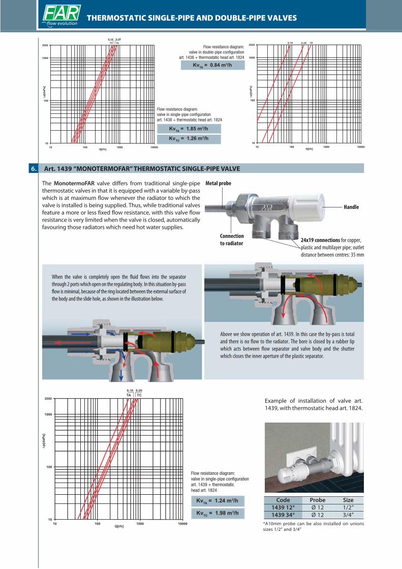
The MonotermoFAR valve differs from traditional single-pipethermostatic valves in that it is equipped with a variable by-passwhich is at maximum flow whenever the radiator to which thevalve is installed is being supplied. Thus, while traditional valvesfeature a more or less fixed flow resistance, with this valve flowresistance is very limited when the valve is closed, automaticallyfavouring those radiators which need hot water supplies.
6. Art. 1439 “MONOTERMOFAR” THERMOSTATIC SINGLE-PIPE VALVE
THERMOSTATIC SINGLE-PIPE AND DOUBLE-PIPE VALVES
10
100
1000
10 100 1000 10000
∆]
aP
ad [
p
Q[l/h]
2000
S-1K S-2K
TATC
10
100
1000
10 100 1000 10000
∆]
aP
ad[
p
Q[l/h]
2000S-1K S-2K TA
Flow resistance diagram:valve in double-pipe configuration
art. 1438 + thermostatic head art. 1824
KvTA
= 0.84 m³/h
Flow resistance diagram:valve in single-pipe configurationart. 1438 + thermostatic head art. 1824
KvTA
= 1.85 m³/h
TC = 1.26 m³/hKv
Handle
Connectionto radiator
Code Probe Size1439 12* Ø 12 1/2”1439 34* Ø 12 3/4”
*A10mm probe can be also installed on unionssizes 1/2” and 3/4”
Example of installation of valve art.1439, with thermostatic head art. 1824.
Above we show operation of art. 1439. In this case the by-pass is totaland there is no flow to the radiator. The bore is closed by a rubber lipwhich acts between flow separator and valve body and the shutterwhich closes the inner aperture of the plastic separator.
When the valve is completely open the fluid flows into the separatorthrough 2 ports which open on the regulating body. In this situation by-passflow is minimal, because of the ring located between the external surface ofthe body and the slide hole, as shown in the illustration below.
24x19 connections for copper,plastic and multilayer pipe; outletdistance between centres: 35 mm
10
100
1000
10 100 1000 10000
∆]
aP
ad[
p
Q[l/h]
2000TA TC
S-2KS-1K
Flow resistance diagram:valve in single-pipe configurationart. 1439 + thermostatichead art. 1824
KvTA
= 1.24 m³/h
KvTC
= 1.98 m³/h
Metal probe

10
100
1000
10 100 1000 10000
∆]
aP
ad[
p
Q[l/h]
2000s-1K s-2K TA
KvTA
= 1.24 m³/h
KvTC
= 1.98 m³/h
Flow resistance diagram:valve in single-pipe configuration
art. 1440 + thermostatichead art. 1824
THERMOSTATIC SINGLE-PIPE AND DOUBLE-PIPE VALVES
7. Art. 1440 “GRT” THERMOSTATIC SINGLE-PIPE VALVE WITH EXTERNAL PROBE
Connectionsto radiator
Lockshieldvalve
Handle
24x19 connections for copper,plastic and multilayer pipe; outletdistance between centres: 35 mm
24x19connections
for copper,plastic and
multilayer pipe
Regulation of the lockshield valve operates the shutter makingit possible to adjust flow in order to achieve the correctbalancing of single-pipe systems. The illustrations show thevariations between 2 differing lockshield regulations. Theshutter closes down by-pass flow, directing the total flow tothe radiator (Fig 1).When operating the lockshield valve as shown in Fig 2, the
Code Size1440 12* 1/2”
Fig. 1: section with completely open valve (70% flowto radiator)
Fig. 2: single-pipe valve section (partial flow toradiator with remainder going to bypass)
Example of installation of valveart. 1440
N.B. the connection probe mustbe ordered separately.
shutter allows the fluid flow in by-pass to increase. Art. 1440can be used with an external probe, from which a side connectioncan be made to a radiator; this ensures efficient operation of theradiator and an easy installation.

Connectionto radiators
Manualvalve
Handle
24x19 connections for copper,plastic and multilayer pipe; outletdistance between centres: 35 mm
24x19 connectionsfor copper, plastic
and multilayer pipe
10
100
1000
10 100 1000 10000
∆]
aP
ad[
p
Q[l/h]
2000TA TCS-2KS-1K
Flow resistance diagram:valve in single-pipe configuration
art. 1442 + thermostatichead art. 1824
KvTA
= 1 m³/h
KvTC
= 2 m³/h
THERMOSTATIC SINGLE-PIPE AND DOUBLE-PIPE VALVES
8. Art. 1442 THERMOSTATIC SINGLE-PIPE VALVE WITH EXTERNAL PROBE
Code Size1442 12 1/2”
Fig. 1: central delivery flow Fig. 2: side delivery flow
Example of installation of valve art. 1442
Example of installation of external probe
The valve is equipped with a flow separator at the side delivery position(Illustration 2). In order to change configuration to central delivery, pleaseproceed as follows:
Unscrew the chrome-platedunion from the valve body andremove the flow separator.
Reverse the flow separator androtate it of 180° as shown inthe illustration
Insert the flow separator insidethe union and screw the uniononce again to the valve body

THERMOSTATIC SINGLE-PIPE AND DOUBLE-PIPE VALVES
9. GENERAL TECHNICAL FEATURES
10. DIMENSIONAL FEATURES
A B* C D E F Ø1 Ø2
1420 12 37 45-107 56 45 35 39 G1/2 24x19
1420 34 37 45-107 56 45 35 39 G3/4 24x19
1420 1 37 45-107 63 48 35 39 G1 24X19
1430 12 37 45-107 56 45 35 39 G1/2 24X19
1430 34 37 45-107 56 45 35 39 G3/4 24X19
1430 1 37 45-107 63 48 35 39 G1 24X19
* = with or without thermostatic head
A B C* D E F Ø1 Ø2
1435 40 53 50-112 35 33 42 G1/2 24x19
* = with or without thermostatic head
A B C* D E F G H Ø1 Ø2
1436 35 53 50-112 35 33 42 26 63 G1/2 24x19
* = with or without thermostatic head
A B C D* E F Ø1 Ø2
1438 12 34 43 41 51-113 35 52 G1/2 24x19
1438 34 34 43 42 51-113 35 54 G3/4 24x19
1438 1D 34 43 44 51-113 35 60 G1 24x19
* = with or without thermostatic head
A B C* D E F Ø1 Ø2
1439 12 41 21 43-105 35 37 11 G1/2 24x19
1439 34 41 21 43-105 35 38 11 G3/4 24x19
* = with or without thermostatic head
A Ø1 Ø2
1941 20 M30x1.5 M20x1
D
Ø2
1Ø
Ø2 F
AB
CØ2
G
H
Ø1
E
A B C D E F G H Ø1 Ø2
1440 12 45 31 42 55 42 35 85 64 G1/2 24x19
A B C D E F G H Ø1 Ø2
1442 12 33 35 39 36 41 29 85 37 G1/2 24x19
A B
1824 86 48
B
A
A B C
1914 66 49 44
1924 66 49 44
CODECODE
CODE
CODE
CODE
CODE
CODE CODE
CODE
CODE
The following technical features are valid for all the products described in this data sheet
Nominal pressure: 10 barMax. working temperature: 95° C
Probe length: 45 cmConnections: for copper, plastic and multilayer pipe
Shutter: EPDMHandle: ABS
Smallware parts: CW614N brassValve body: CW617N brass and CB753S
Nut and union: CW617N brassGaskets, O-rings: EPDM
Probe: zinc-coated steel