thin film tf-lfa laserflash - linseis.com · thickness of less than 2mm (depending on the ......
TRANSCRIPT

THIN FILMLASERFLASH
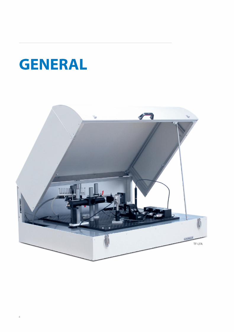
TF-LFA
T H E R M A L A N A L Y S I S

2
Since 1957 LINSEIS company has been deliver-
ing outstanding service, know how and lead-
ing innovative products in the field of thermal
analysis and thermo physical properties.
Customer satisfaction, innovation, flexibility
and high quality are what LINSEIS represents.
Thanks to these fundamentals our company
enjoys an exceptional reputation among the
leading scientific and industrial organizations.
LINSEIS has been offering highly innovative
benchmark products for many years.
The LINSEIS business unit of thermal analysis
is involved in the complete range of thermo
analytical equipment for R&D as well as qual-
ity control. We support applications in sectors
such as polymers, chemical industry, inorganic
building materials and environmental analytics.
In addition, thermo physical properties of solids,
liquids and melts can be analyzed.
LINSEIS provides technological leadership. We
develop and manufacture thermo analytic and
thermo physical testing equipment to the high-
est standards and precision. Due to our innova-
tive drive and precision, we are a leading manu-
facturer of thermal Analysis equipment.
The development of thermo analytical testing
machines requires significant research and a
high degree of precision. LINSEIS Corp. invests
in this research to the benefit of our customers.
Claus Linseis Managing Director

3
Innovation
We want to deliver the latest and best tech-
nology for our customers. LINSEIS continues
to innovate and enhance our existing thermal
analyzers. Our goal is constantly develop new
technologies to enable continued discovery in
science.
German engineering
The strive for the best due diligence and ac-
countability is part of our DNA. Our history is af-
fected by German engineering and strict quality
control.
4
GENERAL
TF-LFA
5
Information of the thermo physical properties
of materials and heat transfer optimization of
final products is becoming more and more vital
for industrial applications.
Over the past few decades, the flash method
has developed into the most commonly used
technique for the measurement of the thermal
diffusivity and thermal conductivity of various
kinds of solids, powders and liquids.
Thermophysical properties from thin-films are
becoming more and more important in indus-
tries such as, phase-change optical disk media,
thermo-electric materials, light emitting diodes
(LEDs), phase change memories, flat panel dis-
plays, and the semiconductor industry. All these
industries deposit a film on a substrate in order
to give a device a particular function. Since the
physical properties of these films differ from
bulk material, these data are required for accu-
rate thermal management predictions.
Based on the well established Laser Flash tech-
nique, the LINSEIS “Thin-Film-Laserflash” now
offers a whole range of new possibilities to
analyze thermophysical properties of thin films
from 80nm up to 20µm thickness.
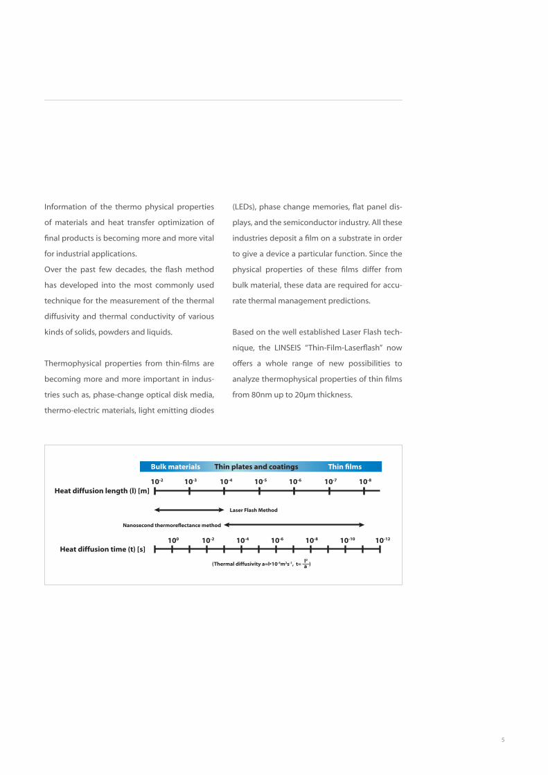
Bulk materials Thin plates and coatings Thin films
10-2 10-3 10-4 10-5 10-6 10-7 10-8
100 10-2 10-4 10-6 10-8 10-10 10-12
Heat diffusion length (l) [m]
Laser Flash Method
Nanosecond thermoreflectance method
Heat diffusion time (t) [s]
(Thermal diffusivity a=l•10-5m2s-1, t= )l2
a

6
LASERFLASH TECHNIQUE
Description of the standard Laserflash techniqueA sample is positioned on a sample holder, lo-
cated in a furnace. The furnace is then held at
a predetermined temperature. At this tempera-
ture the sample surface is then irradiated with
a programmed energy pulse (laser or xenon
flash). This energy pulse results in a homogene-
ous temperature rise at the sample surface. The
resulting temperature rise of the rear surface
of the sample is measured by a IR detector and
thermal diffusivity values are computed from
the temperature rise versus time data. The re-
sulting measuring signal computes the thermal
diffusivity.
For thin layers in the µm or nm range, this ar-
rangement of the standard laser flash technique
is no more sufficient, as the time scale of the ex-
periment is too fast for the used components.
The heating pulse duriation is too long and the
data aquisition too slow. This problem exacer-
bates for materials with higher thermal diffusiv-
ity (see Fig. below).

7
Devi
atio
n [%
]
70
60
50
40
30
20
10
0
d [mm]0 0.5 1.0 1.5 2.0 2.5 3.0 3.5 4.0 4.5 5.0
Ag λ = 418 W/mKCu λ = 398 W/mKW λ = 172 W/mKMo λ = 135 W/mKPt λ = 71 W/mKTi λ = 16 W/mK
The graph from Schoderböck et. al., Int. J. Ther-
mophys. (2009) illustrates the limitation of the
classic Laserflash technique. Samples with a
thickness of less than 2mm (depending on the
thermal diffusivity of the material) already show
a significant deviation from literature values.
8
DESCRIPTION OF THELASERFLASH TECHNIQUE
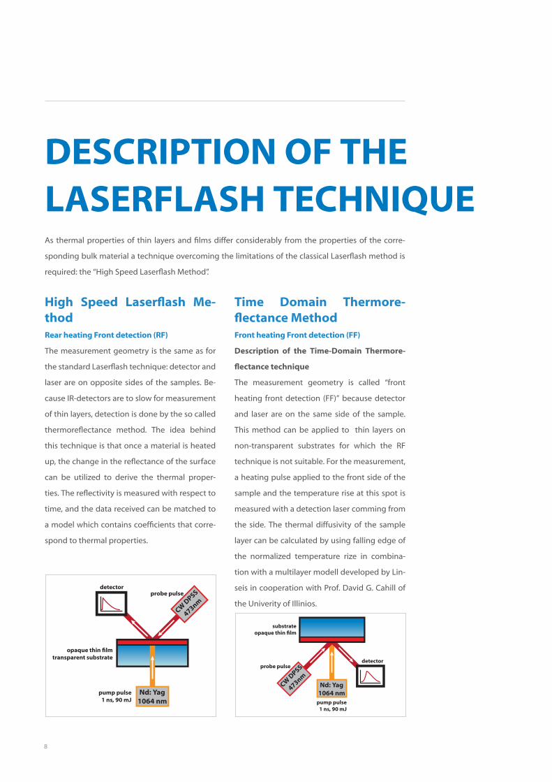
High Speed Laserflash Me-thodRear heating Front detection (RF)
The measurement geometry is the same as for
the standard Laserflash technique: detector and
laser are on opposite sides of the samples. Be-
cause IR-detectors are to slow for measurement
of thin layers, detection is done by the so called
thermoreflectance method. The idea behind
this technique is that once a material is heated
up, the change in the reflectance of the surface
can be utilized to derive the thermal proper-
ties. The reflectivity is measured with respect to
time, and the data received can be matched to
a model which contains coefficients that corre-
spond to thermal properties.
detectorprobe pulse
CW D
PSS
473nm
opaque thin filmtransparent substrate
pump pulse1 ns, 90 mJ
Nd: Yag1064 nm
As thermal properties of thin layers and films differ considerably from the properties of the corre-
sponding bulk material a technique overcoming the limitations of the classical Laserflash method is
required: the “High Speed Laserflash Method”.
Time Domain Thermore-flectance MethodFront heating Front detection (FF)
Description of the Time-Domain Thermore-
flectance technique
The measurement geometry is called “front
heating front detection (FF)” because detector
and laser are on the same side of the sample.
This method can be applied to thin layers on
non-transparent substrates for which the RF
technique is not suitable. For the measurement,
a heating pulse applied to the front side of the
sample and the temperature rise at this spot is
measured with a detection laser comming from
the side. The thermal diffusivity of the sample
layer can be calculated by using falling edge of
the normalized temperature rize in combina-
tion with a multilayer modell developed by Lin-
seis in cooperation with Prof. David G. Cahill of
the Univerity of Illinios.
detectorprobe pulse
CW D
PSS
473nm
substrateopaque thin film
pump pulse1 ns, 90 mJ
Nd: Yag1064 nm
9
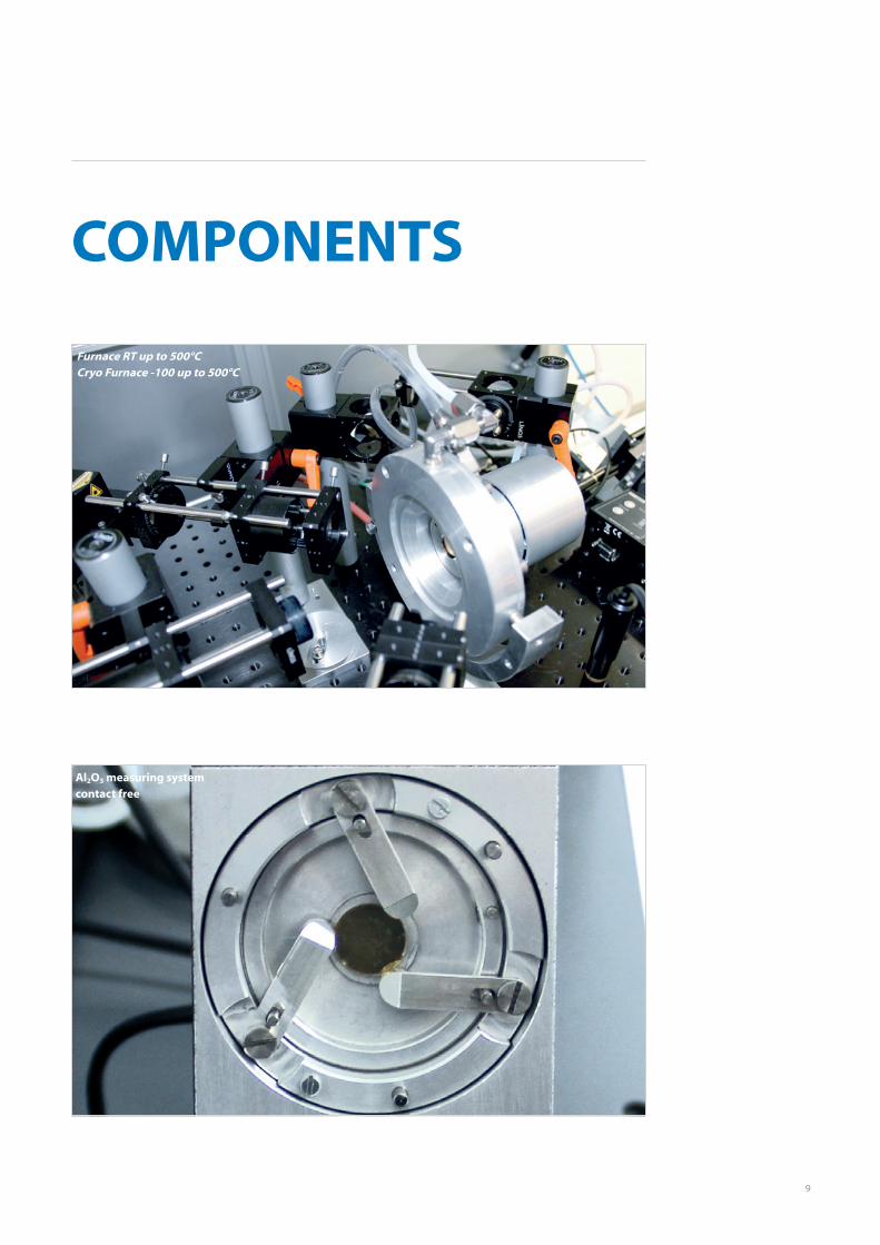
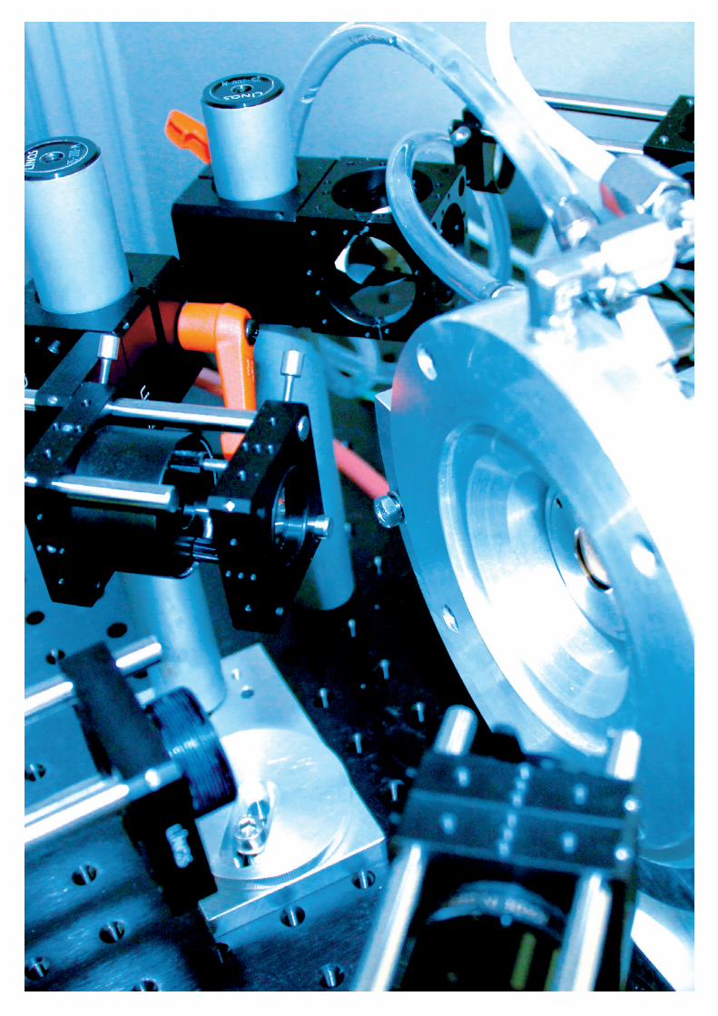
COMPONENTS
Furnace RT up to 500°CCryo Furnace -100 up to 500°C
Al2O3 measuring system contact free
10
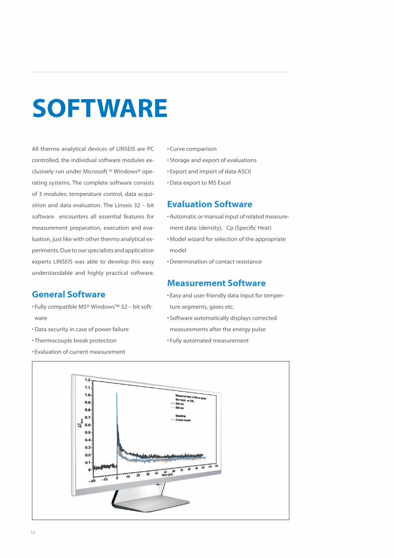
SOFTWAREAll thermo analytical devices of LINSEIS are PC
controlled, the individual software modules ex-
clusively run under Microsoft ® Windows® ope-
rating systems. The complete software consists
of 3 modules: temperature control, data acqui-
sition and data evaluation. The Linseis 32 – bit
software encounters all essential features for
measurement preparation, execution and eva-
luation, just like with other thermo analytical ex-
periments. Due to our specialists and application
experts LINSEIS was able to develop this easy
understandable and highly practical software.
General Software• Fully compatible MS® Windows™ 32 – bit soft-
ware
• Data security in case of power failure
• Thermocouple break protection
• Evaluation of current measurement
• Curve comparison
• Storage and export of evaluations
• Export and import of data ASCII
• Data export to MS Excel
Evaluation Software• Automatic or manual input of related measure-
ment data: (density), Cp (Specific Heat)
• Model wizard for selection of the appropriate
model
• Determination of contact resistance
Measurement Software• Easy and user-friendly data input for temper-
ture segments, gases etc.
• Software automatically displays corrected
measurements after the energy pulse
• Fully automated measurement
11

12
TECHNICAL SPECIFICATIONSThin-Film-LFA
Sample dimensions Round with a diameter of 10mm to 20mm
Thin film samples 80nm up to 20µm (depens on sample)
Temperature range RT, RT up to 500°C or -100 to 500°C
Heating and cooling rates 0.01 up to 10°C/min
Vacuum up to 10-4mbar
Atmosphere inert, oxidizing or reducing
Diffusivity Measuring range 0,01mm2/s up to 1000mm2/s
Pumplaser Nd:YAG Laser (1064 nm), maximum pulse current: 90mJ/pulse(software controled), Pulse width: 5 ns spot size 2-4 mm (depends on arrangement)
Probe-Laser DPSS CW Laser (473 nm, 50 mW)
Photoreceiver Si-PIN-Photodiode, active diameter: 0.8mm, bandwidthDC … 400MHz, risetime: 1ns
13
∆T No
rm
1.2
1.1
1.0
0.9
0.8
0.7
0.6
0.5
0.4
0.3
0.2
0.1
0
Time [µs]–20 –10 0 10 20 30 40 50 60 70 80 90 100 110 120
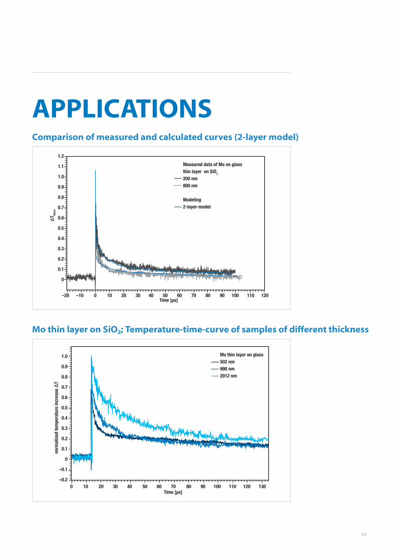
Measured data of Mo on glass thin layer on SiO2
200 nm800 nm
Modeling2-layer-model
APPLICATIONS
norm
aliz
ed te
mpe
ratu
re in
crea
se ∆
T
1.0
0.9
0.8
0.7
0.6
0.5
0.4
0.3
0.2
0.1
0
–0.1
–0.2
Time [µs]0 10 20 30 40 50 60 70 80 90 100 110 120 130
Mo thin layer on glass502 nm998 nm2012 nm
Mo thin layer on SiO2; Temperature-time-curve of samples of different thickness
Comparison of measured and calculated curves (2-layer model)
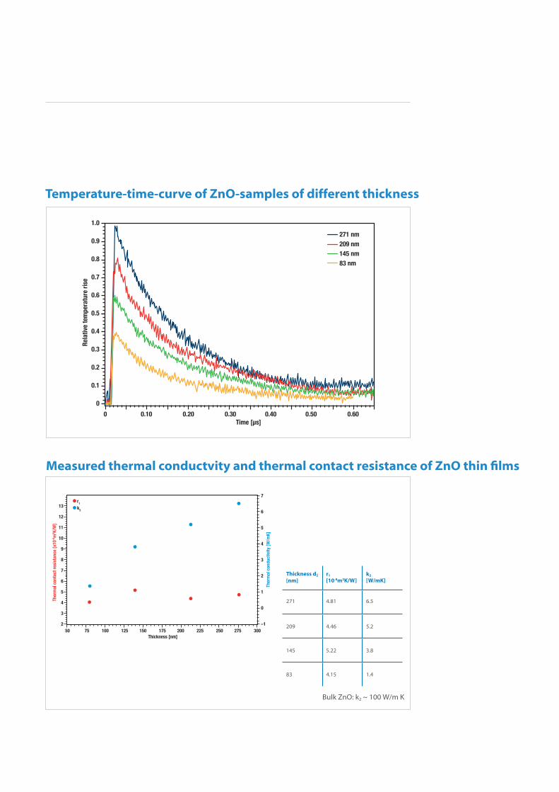
Measured thermal conductvity and thermal contact resistance of ZnO thin films
Ther
mal
con
tact
resi
stan
ce [x
10-6
m2 K
/W]
Ther
mal
con
duct
ivity
[W/m
K]
13
12
11
10
9
8
7
6
5
4
3
2
Thickness [nm]50 75 100 125 150 175 200 225 250 275 300
r1
k2
7
6
5
4
3
2
1
0
–1
Temperature-time-curve of ZnO-samples of different thickness
Rela
tive
tem
pera
ture
rise
1.0
0.9
0.8
0.7
0.6
0.5
0.4
0.3
0.2
0.1
0
Time [µs]0 0.10 0.20 0.30 0.40 0.50 0.60
271 nm209 nm145 nm83 nm
Thickness d2 [nm]
r1 [10-8m2K/W]
k2
[W/mK]
271 4.81 6.5
209 4.46 5.2
145 5.22 3.8
83 4.15 1.4
Bulk ZnO: k2 ~ 100 W/m K
15
Measured thermal conductvity and thermal contact resistance of ZnO thin films
LINSEIS GmbH Germany
Vielitzerstr. 43
95100 Selb
Tel.: (+49) 9287–880 - 0
Fax: (+49) 9287–70488
E-mail: [email protected]
LINSEIS China
Kaige Scientific Park 2653 Hunan Road
201315 Shanghai
Tel.: (+21) 5055 0642
Fax.: (+21) 6806 3576
LINSEIS Poland
Dabrowskiego 1
05-800Pruzkow
Tel.: (+48) 692-773-795
LINSEIS Inc. USA
109 North Gold Drive
Robbinsville, NJ 08691
Tel.: (+1) 609 223 2070
Fax: (+1) 609 223 2074
E-mail: [email protected]
LINSEIS France
Bureaux Paris
52 Boulevard Sébastopol
75003 Paris
Tel.: (+33) 1 73.02.82.72
www.linseis.com
Products: DIL, TG, STA, DSC, HDSC, DTA, TMA, MS/FTIR, In-Situ EGA, Laser Flash, Seebeck Effect, Thin Film Analyzer, Hall-Effect
Services: Service Lab, Calibration Service
08/17