third five-yearreview report solid statecircuits republic
TRANSCRIPT
ThirdFive-Year Review Report
Solid State CircuitsRepublic
Greene County, Missouri
September 2007
Region 7United States Environmental Protection Agency
Kansas City, Kansas
and
Missouri Department of Natural ResourcesJefferson City, Missouri
Approved by: Date:
I IC I
Sup~e;;tW..-ff-n

Table of Contents
1. Introduction , , 12. Site Chronology 23. Background 3
A. Physical Characteristics 3B. Land and Resource Use 6C. History of Contamination ; 7D. Initial Response 7E. Basis for Taking Action 9
4. Remedial Actions 10A. Remedy Selection 10B. Remedy Implementation 11C. Operation and Maintenance 12
5. Progress Since the Last FivecYear Review 14A. Issues Potentially Affecting Current andlor Future Protectiveness 15B. Other Issues Identified During the Previous Five-Year Review 15
6. Five-Year Review Process , 16A. Administrative Components 16B. Community Involvement 16C. Document Review ; 16D. Data Review · 16E. Site Inspection , 19F. Interviews 19
7. Technical Assessment 20Question A 20Question B · 22Question C 24
8. Issues , 259. Recommendations and Follow-Up Actions 2610. Protectiveness Statements 2711. Next Review , : 27
ATTACHMENTS
Attachment A: FiguresAttachment B: Additional TablesAttachment C: Sununary ofTCE Result FromLast Five Years and TCE Trend PlotsAttachment D: Site Inspection PhotographsAttachment E: Site Inspection Checklist and RosterAttachment F: References and List of Documents ReviewedAttachment G: Public Notice and Site Fact Sheet

AgenciesARARsbgsCD/SOWCERCLACFRCOCsCOPCsCWDBRDNREPAESDFYRGMMPMCLsIlg/L
MRACNCPNPLO&MOSWERPCEPOTWppbRARAGSRAORDIRARIfFSRODSBRSPHEMSSCTBC(s)TCEUFSBVOC(s)
List of Acronyms and Initialisms
DNR & EPA combinedApplicable or Relevant and Appropriate Requirementsbelow ground surfaceConsent Decree/Statement of WorkComprehensive Environmental Response, Compensation, and Liability ActCode of Federal RegulationsContaminants or Chemicals of ConcemContaminants or Chemicals of Potential ConcernRepublic's municipal wellDeep BedrockMissouri Department ofNatural ResourcesUnited States Environmental Protection AgencyExplanation of Significant DifferenceFive-Year ReviewGroundwater Monitoring and Management PlanMaximnm Contaminant Levelsmicr0tlrams per liter (VOC concentrations in groundwater are provided in Ilg/L,lxlO· grams per liter)Missouri Remedial Action CorporationNational Contingency PlanNational Priorities ListOperation and MaintenanceOffice of Solid Waste and Emergency ResponseTetrachloroethylenePublicly Owned Treatment WorksParts per billionRemedial ActionRisk Assessment Guidance for SuperfundRemedial Action ObjectiveRemedial Design! Remedial ActionRemedial Investigation! Feasibility StudyRecord of DecisionShallow BedrockSuperfund Public Health Evaluation ManualSolid State CircuitsTo Be Considered(s)TrichloroethyleneUnconsolidated/Fractured Shallow BedrockVolatile Organic Compound(s)
1

Executive Summary
This Five-Year Review (FYR) at Solid State Circuits (SSC) in Republic, Missouri, is pursuant toSection 121(c) of the Comprehensive Environmental Response, Compensation, and Liability Act(CERCLA) Section 121(c); 40 Code of Federal Regulations (CFR) 300.400,(f)(4)(ii); ExecutiveOrder 12580; and Office of Solid Waste and Emergency Response (OSWER) Directives 9355.702 (U.S. Environmental Protection Agency [EPA] 1991), 9355.7-02A (U.S. EPA 1994), and9355.7-03A (U.S. EPA 1995). The trigger for this third FYR is the signing date, September 20,2002, of the second FYR. Issues identified during the previous FYR have been satisfactorilyaddressed.
The third FYR ofthe SSC site, located in Republic, Missouri, was completed in September 2007.The SSC site is well managed, and the system is operating as intended by the design and withinthe requirements specified in the Consent Decree/Statement of Work (CD/SOW). According tothe Five-Year Performance Report prepared by the Missouri Remedial Action Corporation(MRAC) in 2006, long-term trending indicates the progress toward achievement of remediationgOills is ahead of schedule.
Based upon the available data, the assessment of this FYR found the remedy is expected to beprotective of human health and the environment upon attainment of groundwater cleanupstandards. Currently, all threats at the SSC site have been addressed through hydraulic andinstitutional controls of the groundwater contamination.
While the remedy is operating as intended by the design and is meeting the performancerequirements of the CD/SOW, two issues were identified in the FYR that require additionalwork. The two issues requiring further assessment and evaluation are summarized below.
Vapor Intrusion Exposure PathwayThere has been a recent refocus nationwide on the vapor intrusion to the indoor air pathway.This is especially true for sites with trichloroethylene contamination. This issue was consideredduring the remedial investigation but was not found to be a problem. However, for severalreasons, MRAC is currently collecting soil vapor data.
Plume Delineation in the Shallow Bedrock and UnconsolidatedIFractured Shallow BedrockThe nature of contaminant transport in the Unconsolidated/Fractured Shallow Bedrock (UFSB)and monitoring points in the Shallow Bedrock (SBR) and UFSB available for analysis limit thecertainty ofplume delineation. While the existing extraction well network was designed tocapture contamination and maintain or reduce the plume limits, the data available to demonstratethis effect do not fully provide certainty in regard to protection associated with the existinginstitutional controls. An assessment ofpotential exposure points (i.e., private wells) outside thelimits of the well restriction institutional control may provide sufficient data to demonstratecurrent protectiveness. It may also help in determining if any adjustments to the institutionalcontrols are necessary to ensure future protectiveness.
The next FYR for the SSC site is required by September 2012, five years from the date of thisreview.
11

Five-Year Review Summary Form
SITE IDENTIFICATION
Site name (from CERCLlS): Solid State Circuits
EPA ID (fromCERCLIS): MOD 980854111
NPL status: Final
Remediation status: Long-Term Operation and Maintenance
Multiple OUs?* NO Coustruction completion date: 09/2011993
Has site been put into reuse? Source - No, Plume area - Yes
* [au refers to operable umt.]** [Review period should correspond to the actual start and end dates ofthe Five~Year Review in WasteLAN.]
REVIEW STATUS
Lead agency: State of Missouri
Author name: Steve Auchterlonie (EPA) and Candice McGhee (MDNR)
Author title: Remedial Project Manager IAuthor affiliation: EPA Region 7 and MDNR
Review period: March 2006 through September 2007
Date(s) of site inspection: June 4, 2007
Type of review: Post~SARA
Review number: 3
Triggering actiou: Previous Five-Year Review Completion Date
Triggering action date (from WasteLAN): September 20,2002
Due date (five years after triggering action date): September 20, 2007
" "
iii

Five-Year Review Summary Form, cont'd.
Issues:Siltation·ofextraction well SSC-30Potential leak in water supply line in the vicinity of extraction well SSC-30Confirmation of appropriate coverage by the institutional controls designed to protect againstexposure to contaminated groundwater; delineation of trichloroethylene at or below theMaximum Contaminant Level in the UnconsolidatedlFractured Shallow Bedrock andShallow BedrockVapor Intrusion Pathway
Recommendations and Follow-up Actions:Determine the impact of siltation on remedy performance and effectiveness. Potentialsolutions include but are not limited to install a new well with deeper pump intake and installa new casing and screen inside the existing well.Assess the impact of the leaking/potentially leaking water line in the vicinity of extractionwell SSC-30, provide an evaluation in terms of remedy performance and effectiveness, andprovide recommendations for mitigating or eliminating ancillary issues stemming from thewater line leak.Determine the most effective means for confirming appropriateness of the institutionalcontrol coverage area; possible paths include but are not limited to new monitoring wells toenhance plume delineation, downgradient private well survey, and general increase ininstitutional control coverage area.Continue evaluation ofthe vapor intrusion exposure pathway; possible paths include but arenot limited to soil gas samples, indoor air monitoring, plume delineation, and modeling.
Protectiveness Statement(s):Based upon available data, the assessment of this FYR found the remedy is expected to beprotective of human health and the environment upon attainment of groundwater cleanupstandards. Currently, all threats at the SSC site have been addressed through hydraulic andinstitutional controls of the groundwater contamination. While the remedy is operating asintended, two issues require further assessment: vapor intrusion and plume delineation.
iv

Solid State CircuitsRepublic, Missouri
Third Five-Year Review Report
1. INTRODUCTION
The purpose of a five-year review (FYR) is to determine whether the remedy at a site isprotective ofhnman health and the environment. The FYR report docnments the methods,findings, and conclusions of a review including any identified issues and recommendations toaddress them.
The U.S. Army Corps of Engineers (USACE) has prepared this FYR report on behalfof theMissouri Department ofNatural Resources (DNR), the lead agency for this National PrioritiesList (NPL) site, and on behalfof the U.S. Environmental Protection Agency (EPA), pursuant tothe Comprehensive Environmental Response, Compensation, and Liability Act (CERCLA) §121and the National Contingency Plan (NCP). CERCLA §121 states:
Ifthe President selects a remedial action that results in any hazardous substances, pollutants, orcontaminants remaining at the site, the President shall review such remedial action no less often than eachftve years after the initiation ofsuch remedial action to assure that human health and the environment arebeing protected by the remedial action being implemented. In addition, ifupon such review it is thejudgment ofthe President that action is appropriate at such site in accordance with section [I04] or [I06],the President shall take or require such action. The President shall report to the Congress a list offacilities for which such review is required, the results ofall such reviews, and any actions taken as a resultofsuch reviews.
The NCP, 40 CFR §300.430(f)(4)(ii), states:
Ifa remedial action is selected that results in hazardous substances, pollutants, or contaminants remainingat the site above levels that allowfor unlimited use and unrestricted exposure, the lead agency shall reviewsuch action no less often than everyftve years after the initiation ofthe selected remedial action.
This FYR for the Solid State Circuits (SSC) site in Republic, Greene County, Missouri, wasconducted from September 2006 through September 2007. The review was initiated by DNR,and USACE was added to the team in May 2007 as the primary author. This is the third FYR forthe SSC site. The first FYR was approved in December 12,1996. The second FYR wasapproved September 20, 2002. The approval date of the second FYR is the trigger date for thisFYR. The FYRs continue because hazardous substances, pollutants, or contaminants remain atthe SSC site above levels that allow for unlimited use and unrestricted exposure.
This third FYR report summarizes:
• Site background information• Remedial Action (RA) activities• Performance and operational monitoring results• Site inspections• Data review

• Remediation progress and status at the site
The information summarized in this report was obtained from the SSC site RemedialInvestigation (RI) Report, Record of Decision (ROD), the Consent DecreelStatement of Work(CD/SOW), sections of the 100 Percent Remedial Design Document Package (RDDP),the FirstFYR Report (December 1996), the Second FYR Report (September 2002), quarterly hydraulicperformance reports, annual chemical monitoring reports for the years 200 I through 2006, andother relevant documents. Attachment F lists all the documents reviewed for this FYR.
2. SITE CHRONOLOGY
1: bl 1 S' Ch Ia e : Ite rona o,gyEvent DateSSC Site Manufactured Printed Circuit Boards 1968 to 1111973TCE Discovered in CW-1 During NSOC Survey 06/1982Agencies Conducted Response Activities 0411983 to 03/1984SSC Site Placed on the Missouri Registry of Sites 02122/1985DNR and Responsible Parties Conducted Removal Activities 03/1985 to 1111985EPA Signed Action Memorandum 04/05/1985EPA Conducted Removal Activities 04/05/1985 to 10/3111985Final Listing on EPA NPL 06110/1986Cost Recovery Settlement Agreement & Consent Decree Entered 11/20/1986by Federal CourtSSC Site Conducted RIfFS . 12/1986 to 0711989ROD Selecting the Remedy is Signed 09/27/1989Consent DecreelStatement of Work (CD/SOW) Entered by Court 0511991RD Pilot Remediation Program 09/0111991 to 0113111992MRAC's RD Approved by DNR with EPA Concurrence 12/2211992Implementation ofRA Construction 01/1111993RA Construction Completion Date 09/20/1993Preliminary Close Out Report Received by DNR 12/01/1993RA Certification Report Received bv DNR 05/1994RA Operation & Maintenance (O&M) Plan Approved 05/1994ESD Issued by DNR with EPA Concurrence, Regarding 10/2411996Modification ofUFSB and DBR Chemical Quality and HydraulicPerformance MonitoringFirst Five-Year Review Approved 12112/1996Horizontal Well Pilot Test 2001-2002Second Five-Year Review Approved 09/20/2002ESD to Allow Full Operation ofHorizontal Well 09/2004Public Notice for Start of Five-Year Review Process 03/28/07Site Inspection for Five-Year Review 06104/07
2

3. Background
This section presents SSC site background information including the physical characteristics ofthe SSC site, land and resource use, history of contamination, initial responses to thecontamination at the SSC site, and the basis for the RAs taken at the SSC site.
A. Physical Characteristics
Site Location
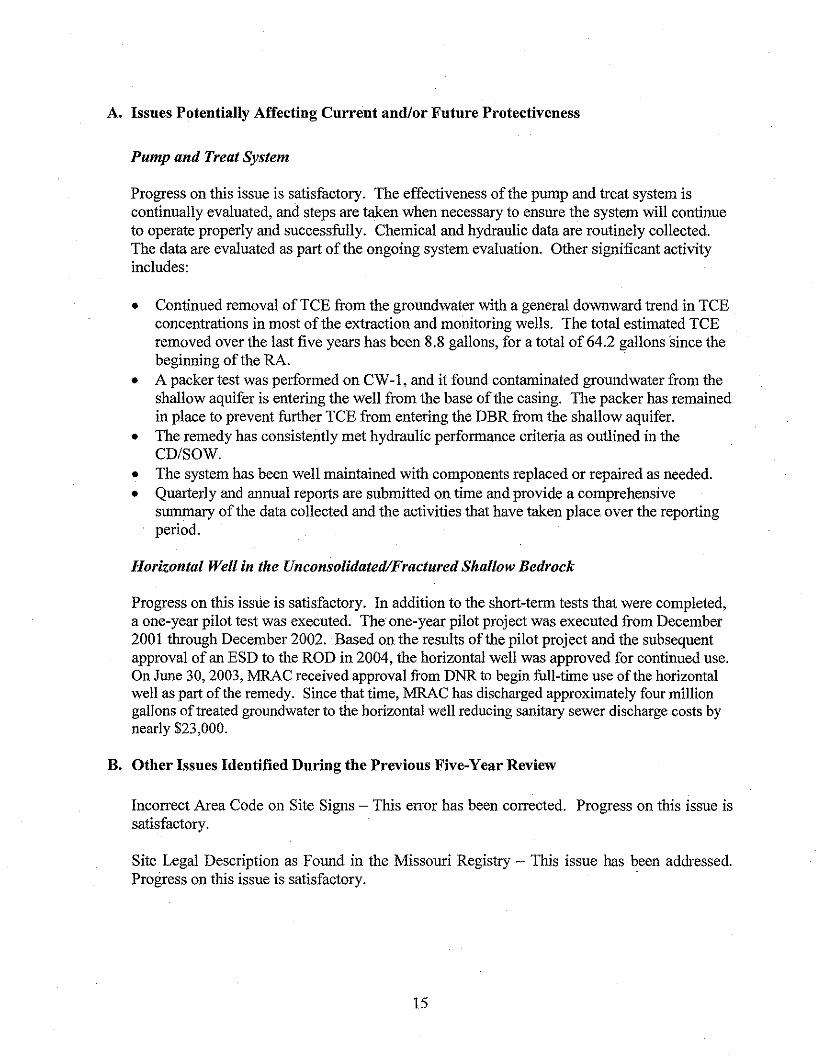
SSC is located in T28, R23W Section 20, at 37° 01' 05" N, 93° 28' 48" W. The SSC site islocated on the southeast corner ofthe intersection of Main Street and Elm Street indowntown Republic, Missouri, as shown on Figure I. Republic is approximately 12 milessouthwest of Springfield in Greene County, Missouri, and has a population of approximately13,000 residents.
The SSC site includes the northern end of the former plant building, the soils below andaround the former building, and impacted on-site and off-site portions of the underlyinggroundwater aquifers. The site of the former plant building is less than one acre in size andis secured with a six-foot high chain-link fence. The original building and basementextended the entire length of Main Street between Mill and Elm Streets. The northernportion of the building was four stories tall while the remaining portion was one story. TheSSC site and former plant building have a relatively unclear history and very little is knownabout chemicals used on-site, although it had been leased or owned by numerous businessesthrough the years. The plant building was constructed prior to 1902 and was originallyoperated by a milling company. Circa 1902 to 1937, a cold refrigeration plant operated in thenorthern portion of the building.
SSC operated in the northern portion ofthebuilding from 1968 until November 1973.During that time, SSC manufactured printed circuit boards and used trichioroethy1ene (TCE)in the cleauing process.
Micrographics, Incorporated, a photographic-processing firm, operated from 1973 until 1979at the SSC site. In November 1979, the northern end of the building was destroyed by fire,the damaged portion was demolished, and the debris was pushed into the basement. Thebasement area was then filled to grade for use as a gravel parking lot. The remaining portionofthe building was repaired and refurbished.
Crane Manufacturing Company of Crane, Missouri, purchased the property and then soldit to Mr. Nicholas Weinsaft who owned it from 1976 until 1998. In 1998,Mr. Lance McKnelley and Mr. Don Rogers purchased the property. Mr. McKnelley sold hisportion to Mr. Rogers in 1999. Landon Enterprises, Inc., is the current owner.
3

Geological and Hydrogeological Characteristics
The SSC site is located within the Springfield Plateau section ofthe Ozark Plateauphysiographic province of the Interior Highlands major division. The city of Republic islocated on a northeast-southwest trending topographic high that serves as a drainage divide.Elevation at the SSC site is approximately 1,300 feet above mean sea level. Northern surfacedrainage flows toward Dry Branch and Pickerel Creek which then flows into the Sac River.The Sac River lies within the Osage River drainage basin. Southern surface drainage flowstoward Shuyler Creek which then flows into Wilson Creek. Wilson Creek flows into theJames River. These drainages lie within the White River drainage basin.
Surface soils in the vicinity of the SSC site are classified as Creldon silt loam and areconsidered to be deep and moderately well drained. These soils are generally formed on thetops and sides of ridges and upland areas. Soils beneath the SSC site consist of a sandybrown clay containing fragments of weathered limestone and are considered to berepresentative of fill material rather than naturaily occurring soil. Off-site soils arecommonly a medium to dark brown silty clay loam that contain some sand and weatheredlimestone fragments. Subsurface soils are generally 15 to 25 feet thick and consist ofresiduum weathered from the underlying bedrock. These soils typically grade from amedium brown silty clay to a brownish orange-red silty to sandy dense clay containing chertand weathered limestone fragments. Increasing sand and gravel are encountered near thebedrock contact.
Bedrock beneath the SSC site consists of in descending order - Mississippian, Ordovician,Cambrian, and Pre-Cambrian units. The Mississippian-age Burlington-Keokuk Limestone isthe uppermost bedrock formation in the vicinity ofthe SSC site and can range from 80 feetup to 230 feet thick in the Ozark Plateau region. The formation is a coarse crystallinelimestone that commonly contains discontinuous beds of chert. The upper portion has beenintensely weathered resulting in the overlying residuum. Beneath the Burlington-KeokukLimestone are the Mississippian Elsey, Reeds Spring, and Pierson Formations. The Elseyand Reed Springs Formations are described as fine-grained to argillaceous cherty limestonewhile the Pierson Formation is described as a dolomitic limestone. Below these formationslies the Mississippian Northview Formation, a shale-to-shaley limestone unit which ranges inthickness from 5 to 30 feet across the region. Below the Northview lies the MississippianCompton Limestone, a dense limestone unit which is underlain by a very thick sequence ofOrdovician and Cambrian units which are composed of limestone, dolomite, and sandstonewith some discontinuous beds of siltstone and shale. The Pre-Cambrian bedrock consists ofmetasedimentary and igneous rocks which comprise the basement complex. A cross-sectionof the subsurface geology is shown on Figure 2.
Periodic uplifting of the Ozarks Plateau region has resulted in extensive faulting, fracturing,and the development ofjoints in the bedrock. Locally, numerous structural featuresincluding lineations have been identified in the Republic, Missouri, area. Work performedduring the RI identified a fracture zone in the upper portion of the shallow bedrock that tracesfrom the SSC site along Main Street southward. South of city well CW-l, the fracture zonetraces toward the southeast near extraction well SSC-3l.
4

Groundwater flow in clastic sedimentary and crystalline (limestone/dolomite) rocks variesdepending upon the porosity, permeability, and structural features of the rocks. Hydrologiccharacteristics of these rocks may be impacted by cementation and compaction of the porespaces as well as sedimentary structures including bedding planes. Limestone and dolomitetypically have both low porosity and primary permeability due to the crystalline nature of therock. Secondary permeability can be attributed to fracturing and the development ofjoints inthe rock, and it is dependant upon the number and size ofthe fractures. Groundwater flowchannels are enlarged via the dissolution of limestone or dolomite as unsaturated water withrespect to calcite and dolomite flows through fractures, joints, and bedding planes.Dissolution of the limestone and dolomite can result in the development of karst topography.Karst features include springs, losing streams, sinkholes, and caves. Southwest Missouri ischaracterized by karst topography which often affects the surface water hydrology such asShuyler Creek which is classified by DNR as a losing stream. Stream flow in Shuyler Creekis lost to the shallow bedrock aquifer and is thought to feed Roberts Spring (Figure 1).
The groundwater system within the Ozark Plateau region is characterized by seven majorhydrogeologic units which have been subdivided into three major aquifers and four confiningunits. These units are based on geologic and hydraulic properties including permeability andwell yields. The SSC site is located within the Springfield Plateau aquifer unit which is asub-hydrogeologic unit of the Ozark Plateaus Aquifer System. The aquifer units which areof importance in the Republic, Missouri, area include in descending order - the SpringfieldPlateau aquifer, the Ozark confining unit, and the Ozark aquifer. Bedrock units beneath theSSC site that correlate to these aquifer units include: (1) the shallow bedrock unitSpringfield Plateau aquifer, (2) the Northview Formation/Compton Limestone - the Ozarkconfining unit, and (3) the deep bedrock unit - the Ozark aquifer. The Springfield aquifer isan unconfined aquifer in the Republic, Missouri, area.
Site-specific hydrogeologic units have been identified in the vicinity of the SSC site. Theupper-most aquifer unit at SSC is designated as the UnconsolidatedlFractured ShallowBedrock (UFSB) unit which includes the saturatedportion of the unconsolidated residuumand the fractured/weathered portion of the upper shallow bedrock unit. The UFSB extends toapproximately 70 feet below ground surface (bgs). Below the UFSB unit is the unfracturedShallow Bedrock (SBR) unit which extends approximately 230 feet to the top of theNorthview Formation. The Northview Formation/Compton Limestone confining unit rangesin thickness between 15 to 30 feet. Below the Northview Formation/Compton Limestone isthe Deep Bedrock (DBR) unit which extends to approximately 1,300 feet bgs.
In the SBR and DBR units groundwater is thought to flow in zones ofhigher porosity and.along bedding planes. Dissolution of the limestone and dolomite bedrock results inincreased groundwater storage and flow. The deeper portion ofthe SBR is thought to be lesspermeable than the UFSB, although a zone ofhigher porosity was detected between 177 feetand 209 feet bgs during borehole geophysical studies conducted during the RI. The UFSB toabout 70 feet bgs is not considered a significant water producer. The lower portion of theSBR to about 300 feet bgs can locally produce about 100 gallons per minute (gpm).
5

Regional groundwater flow in the Springfield and Ozark aquifers is toward the southsoutheast which was confirmed by pre-remedial groundwater level measurements andpotentiometric surface maps constructed during the RI. However, due to the largegroun~waterwithdrawal rate by the Springfield municipal well field, groundwater flow in theDBR IS generally to the northeast (toward Springfield). Republic's municipal wells locatedto the west and northeast of the SSC site are also installed into the deep Ozark aquifer. Thesewells also influence the direction of groundwater flow within the DBR on a local scale whenp~ping. The effect of the pumping wells on the SBR is limited due to the Ozark confi~ingumt, although on a small scale there may be some influence due to well-specific constructionand the potential for downward leakage within the annular space.
On a local scale, groundwater flow in the UFSB and SBR is toward the Shyuler CreekdIainage basin and Roberts Spring. On a site-level scale, groundwater flow in the UFSB isgenerally toward the Main Street fracture zone which is thought to act as a hydIaulic sink.Studies performed during the RI indicate there is hydraulic communication between theUFSB and the SBR. Groundwater level measurements indicate there is a downwardhydraulic gradient between these aquifer units. A vertical hydraulic gradient exists across theNorthview/Compton Limestone which is considered to act collectively as a leaky-confiningunit to the underlying Ozark aquifer. Due to considerable pumping of the DBR aquifer formunicipal and industrial use, an increase in leakage across these units into the DBR mayoccur.
B. Land and Resonrce Use
The area surrounding the SSC site is predominantly urban. Currently, residential areas existto the east, west, and two blocks to the south. Most of the dwellings are single family homesalthough a small apartment complex is located across Main Street from the complex ofwellsnear old city well CW-1. Commercial properties including l~ght ~dustry and v.:arehouses areintermingled with the single family dwellings to the west. LIght mdustry and cIty propertyare located to the north and south of the SSC site. A daycare facility is located to the north ofthe SSC site across Elm Street.
Inset Showing the Solid State Circuits Site
6

The city of Republic provides potable drinking water from water supply wells located invarious locations around the city. Currently, municipal wells CW-3, CW-4, and CW-5 areoperational and supply Republic's water needs. TCE contamination has only been detectedin Republic's CW-1 which was taken out of service in July 1983. Republic's CW-2 wastaken out of service in the fall of 1997 for nonTCE-related issues. The only groundwateraquifer unit that supplies water to the three functioning Republic municipal wells is the DBR.
C. History of Contamination
SSC manufactured printed circuit boards at the site from 1968 through 1973 in the building'snorth end. Volatile organic compounds (VOCs) and metals were used in the manufacturingand plating process. Solvents such as TCE were used in the cleauing process. Due to a lackofviable records, a reliable estimate ofthe volume of hazardous substances used is notavailable.
TCE was reportedly stored in the north-end basement sump pit, near the basement well.Early sampling data indicated the improper management of spent TCE and copper-platingsolutions caused the on-site and off-site contamination of surface and subsurface soils, air,utility conduits, and groundwater. The elevated VOC concentrations in the on-sitesubsurface soils and groundwater beneath the SSC site indicated an on-site release hadoccurred. The off-site groundwater contamination had also affected Republic's municipalwater supply well ew-1.
D. Initial Response
Regulatory Agency Involvement
DNR collected water samples from Republic's three municipal wells and the distributionsystem in June 1982 as part of the EPA National Synthetic Organic Chemical Survey. TCEcontamination was detected in municipal well CW-1 which triggered further investigations.Between April 1983 and March 1984, EPA and DNR iuitiated response actions to identifycontaminant sources and to further investigate the TCE occurrence in the CW-1 well. Theformer SSC manufacturing and plating plant was identified as the source ofthe TCEcontamination.
On August 26, 1983, DNR notified the property owner the SSC site was proposed forinclusion on the Missouri Registry ofConfirmed Abandoned and Uncontrolled HazardousWaste Disposal Sites. The listing was appealed and an agreement was reached at which timethe SSC site was placed on the Registry on February 22, 1985.
The sse site was proposed for listing on the NPL on October 15,1984. On October 1, 1985,a Multi-Site Cooperative Agreement was signed by EPA and DNR; and on October 7, DNRassumed the long-term responsibility of the SSC site. The sse site was listed on the NPL onJune 10, 1986.
7

Removal History
DNR, with some participation from the responsible party, conducted removal responseactivities at the SSC site in four phases (March through November 1984). Extensive soil andgroundwater sampling was done to delineate the on-site and off-site contamination.Contaminated on-site soils and debris were excavated from and around the basement of theformer plant. Due to the Resource Conservation and Recovery Act disposal requirements, aportion of the excavated materials was stored on-site until a proper disposal facility waslocated. The remaining materials were shipped to an off-site disposal facility. Threemonitoring wells were installed, and a wooden fence was installed for site security.
On April 5, 1985, EPA signed an Action Memorandum to undertake an immediate removalaction. This removal action was conducted during April 1985 through November 1985. Todetermine the necessary extent of the removal, additional soil and groundwater sampling wasperformed. Sample results indicated sub-basement soils and debris were highlycontaminated. All material was excavated to bedrock and shipped off-site for disposal alongwith the previously stockpiled contaminated materials. The basement well was abandonedper Missouri state regulations, and the excavation was filled to grade with clean materials.Four additional off-site monitoring wells and two on-site recovery/monitoring wells wereinstalled. A chain-link fence with barbed wire and a locking gate were installed for addedsite security. Final grading and seeding were completed on October 31,1985.
Remedial History
In December 1985, the responsible party submitted a plan to DNR to conduct a RemedialInvestigationlFeasibility Study (RIfFS) at the SSC site. The RIfFS was conducted fromDecember 1985 until July 1989. During this time, multi-media monitoring and samplingevents were conducted and included on-site and off-site air, surface, and sub-surface soils,utility corridors, surface water, and groundwater. Additional work included the installationof monitoring wells and the construction of a new municipal water supply well CW-4. Apilot program was implemented to evaluate the extraction and treatment of the contaminatedgroundwater.
The RI identified TCE and other VOC contamination in the three hydrogeologic units bothon-site and off-site. The completed RIfFS and the Proposed Plan were released to the publicon August 14,1989. Since the previous response actions had addressed the contaminated onsite soils and debris, the ROD only addressed the contaminated groundwater. The selectedremedy included extraction and treatment of the groundwater and discharge to the city ofRepublic's Publicly Owned Treatment Work (POTW) facility. The ROD was approved andsigued on September 27, 1989.
Between December 1989 and July 1990, the Agencies (DNR and EPA) and the responsibleparty negotiated the terms for the CD/SOW for the Remedial Design/Remedial Action(RD/RA) in accordance with the ROD. Near the end of negotiations, the responsible party
8

sold the SSC site's assets and the money was placed in trust to finance the remedial work.The effective date for the CD/SOW was in May 1991. The Trust Agreement was approvedin October 1991.
E. Basis for Taking Action
Data collected during the various investigations and removal activities at the SSC siteidentified over 33 contaminants of potential concem (COpes) on-site and/or off-site.Contamination, predominantly TCE, was detected in various media including on-site and offsite soils, groundwater in the three hydrogeologic units, utility corridors and manholes, andthe influent to the POTW. The following is a list of detected COPCs and their locations:
On-site Groundwater: Cadmium; chromium; iron; mercury; nickel; zinc; benzene; carbontetrachloride; cWorobenzene; chloroethane; chloroform; 1,I-dichloroethane;1,I-dicWoroethene; 1,3-dicWoropropylene; ethylbenzene; methylene chloride;tetrachloroethylene (PCE); toluene; trans-I ,2-dichloroethene; 1,1, I-trichloroethane;1,1,2-trichloroethene; TCE; vinyl chloride; acetone; and I,2-dichloroethylene.
Off-site Groundwater: Lead; magnesium; manganese; 1,2-dicWoroethane;1,2-dichloropropane; methyl cWoride; 2-butanone (MEK); TCE; and carbon disulfide.
RepUblic's Drinldng Water: Copper and TCE.
On-site Soil: Benzene; 1,I-dichloroethane; 1, I-dichloroethene; methylene chloride; PCE;,trans-I,2-dichloroethene; 1,1, I-trichlorothane; 1,1 ,2-trichloroethene; TCE; and vinylchloride.
Off-site Soil: Chloroform, ethylbenzene, toluene, and TCE.
Sewer: Chloroform; 1, l-dicWoroethane; ethylbenzene; toluene; trans-I ,2-dichloroethene;I,I,I-trichloroethane; and TCE.
SW Bell Telephone: I,I-dichloroethane; I,3-dichloropropylene; methylene cWoride; andTCE.
Due to the large number of COPCs and the wide variations in occurrence, concentrations,and toxicities found between the COPCs, a selection process was implemented to identifycontaminants of concern (COCs) for evaluation in the risk assessments. The COCs chosenfocused on contaminants that would probably cause risk to human health and theenvironment. Metals were not considered COCs because the concentrations were found atlevels below health standards. The COCs included: 1, I-dichloroethane; 1, I-dicWoroethene;trans-I,2-dicWoroethene; methylene chloride; 1,1, I-trichloroethane; TCE; and vinyl cWoride.These COCs were used in the Human Health and Ecological Risk Assessments.
9
At the time of the risk assessments, federal and state standards and criteria existed to protectdrinking water and fresh-water aquatic life. The federal standards (Maximum ContaminantLevels [MCLs]) and/or Missouri Water Quality Standards existed for the 1,2-dichloroethene,methylene chloride, 1,1, I-trichloroethane, TCE, and vinyl chloride. Safe Water DrinkingAct MCL Goals existed for trans-l ,2-dichloroethene. No regulatory standards existed forl,l-dichloroethane.
Based on the Human Health Risk Assessment, "no unacceptable" health risks wereidentified, but there was the potential for future unacceptable risks. Future risks were basedon dermal contact or ingestion of the contaminated groundwater. To prevent future risk, acity ordinance was established stating no private or public wells would be installed in or nearthe contaminant plumes, and the remediation of the contaminated groundwater wouldcontinue as required.
Based on the results of the Ecological Risk Assessment, no adverse effects were identifiedfor terrestrial or aquatic ecosystems. There was no indication of threatened or endangeredwildlife species; however, it was determined should Roberts Spring become contaminated bysite-related groundwater in the future, it would pose a new risk.
4. Remedial Actions
A. Remedy Selection
As previously indicated, the ROD for the SSC site was signed on September 27,1989. TheRemedial Action Objectives (RAOs) were developed to aid in the screening ofremedialalternatives proposed in the 1989 FS. The RAOs were divided into source control andmanagement of migration response objectives and included the following:
Source Control Response Objectives
• Prevent potential exposure to contaminated groundwater by containment andremediation.
• Protect uncontaminated groundwater for future use by preventing furthermigration ofcontaminated groundwater plumes.
• Restore contaminated groundwater for potential, future residential use by reducing theTCE concentration to less than 5 parts per billion (Ppb) -the MCL for TCE ingroundwater.
• Protect the city of Republic's water supply for current and future use by preventing thespread of the contamination.
Management ofMigration Response Objectives
• Eliminate or minimize the threat posed to human health and the environment bypreventing exposure to groundwater contaminants.
• Prevent further migration of groundwater contamination beyond its current extent.
10

• Restore contaminated grolUldwater to federal and state applicable or relevant andappropriate requirements (ARARs), including drinking water standards, and to a levelthat is protective of human health and the environment within a reasonable period of time
As the previous response actions had addressed contaminated soil, the remedial alternativesevaluated in the FS addressed only the three contaminated hydrogeologic units. Thefollowing describes the components of the remedy selected in the ROD:
I. Extraction of the contaminated grolUldwater from the three hydrogeologic lUlitS byexisting and new extraction wells.
2. On-site treatment of the extracted grolUldwater using the two existing air strippers.3. Discharge of treated water to the city of Republic sewer system to receive further
treatment at the POTW.4. Issuance of a city ordinance to prohibit construction ofpublic and private water supply
wells in areas and hydrogeologic lUlits of known grolUldwater contamination.5. Continued grolUldwater monitoring to determine the effectiveness of the remedy.
The following describes the management components of the remedy selected in the ROD:
1.· The use of the pump and treat system to achieve groundwater cleanup levels.2. A review ofplarmed drinking wells to prevent their construction within or near the
contaminated grolUldwater plumes as defined in the city ordinance.3. Chemical quality and hydraulic performance monitoring data collection.4. Periodic agency site inspections.5. Conduct FYRs to assess site conditions, contaminant distribution, and any associated site
hazards.
B. Remedy Implementation
Prior to issuance of the ROD, an earlier pilot treatment system had been installed at the SSCsite to address the on-site grolUldwater contamination. As part of the RDIRA process, asecond pilot study was initiated to test various extraction well pumping schemes in order tobetter define the pumping and discharge rates. The results of the pilot study wereincorporated into the RDDP which was submitted to the Agencies. The responsible partysubmitted the designs and specifications for the upgraded mechanical air stripping systemand proposed increase in the stack heights of the two existing air strippers, sewer level sensorsystem, the design specifications for the proposed Data Management System, and the resultsof the Air Modeling Study. In October 1992, the Agencies received the 100 Percent RDDPand determined the proposed system for removing TCE from the contaminated water was 98to 99 percent efficient. On December 22, 1992, DNR approved and EPA concurred with the100 Percent RDDP for the grolUldwater cleanup alternative.
RA construction began on January 11, 1993. Construction activities included the installation,testing, and sampling of extraction and monitoring wells and the treatment system.Republic's CW-2 well was taken offline due to non-site-related activities, and the newmlUlicipai well, CW-5, was constructed and brought online. RA construction activities were
11

completed on September 20,1993. On October 29, 1993, DNR sent EPA the PreliminaryClose Out Report for the long-term RA at the SSC site. EPA approved and signed thedocument and it was returned to DNR on December 1, 1993. In March 1994, DNRconducted a pre-certification inspection of the RA at the SSC site per the CD/SOW. Theinspection determined the RA construction was complete and the remedy was operationaland functional. Hydraulic control of the three hydrogeologic units had been achieved andmaintained. EPA concurred on May 19, 1994.
On May 31, 1994, DNR received the RA certification report and As-Built Drawings for theSSC site. The Agencies sent the responsible party the DNR "Certification of Completion ofthe Remedial Action" for the SSC site in September 1994. The document notified theresponsible party the remedy for the SSC site was operational and functional, and it initiatedthe SSC site's long-term RA A schematic diagram of the treatment system is provided inFignre 3.
Elements of the RA include:
• The extraction of contaminated groundwater from the three hydrogeologic units-theUFSB, the SBR, and the DBR.
• The treatmeht of the extracted.contaminated groundwater using the on-site air strippers.• The discharge of treated groundwater to the Republic sewer system for additional
treatment at the POTW.• The issuance ofa city ordinance restricting the construction of water supply wells into
areas of known groundwater contamination.• Continued monitoring and reporting of the treatment system, contaminant plumes, and
contaminated groundwater via the chemical quality and the hydraulic performancemonitoring reports.
Part of the long-term RA includes continuation of the long-term, site-specific remedialactivities including operation of the pump and treat system, the ongoing monitoring andreporting of these activities, and periodic review of Republic's well construction ordinancewhich was originally implemented in 1993. After groundwater cleanup levels have beenmet, the Agencies will issue a Final Close Out RepOlt. With responsible management of thetrust and regular Agency review, it is projected enough funds will exist to cover future costs.
C. Operation and Maintenance
MRAC is conducting, with the Agencies' oversight, long-term RA operation andmaintenance (O&M) ofthe SSC site according to the O&M plan that was jointly approvedby the Agencies on June 16, 1994. The O&M plan set forth system procedures andequipment maintenance procedures to be implemented for effective day-to-day and long-termoperation of the selected remedy for the SSC site. The primary activities associated withO&M include the following:
• Remedial system descriptions• Normal operating, inspection, and maintenance procedures and schedules
12

• Potential operating problems and operation troubleshooting• Equipment monitoring and inspection requirements• Monitoring requirements to ensure appropriate O&M ofthe recovery and treatment
systems• Contingent corrective action provisions• Recordkeeping and reporting requirements to include personnel and safety
On September 23,1994, DNR received the final copy of the "Addendum Report to the RAGroundwater Monitoring and Management Plan (GMMP)." The GMMP contains thespecific tasks required to evaluate the monitoring activities and site management as part ofthe groundwater RAs and their progress. This includes the requirements of the hydrauliccontrol measures for the three hydrogeologic units, management of the extraction andmonitoring wells, data collection and analysis, management practices, data reperting, andquality assurance/quality control requirements.
The requirements for the SSC site groundwater remedy are in accordance with the RDIRACD/SOW that was entered into court on May 31,1991. The CD/SOW defines the schedulefor the submittal of the progress reports which are submitted by MRAC for the Agencies'approval. This schedule was initiated following the approval of the 100 Percent RDDP. Thereports document the chemical quality and hydraulic performance monitoring. These reportsand additional DNR split sampling are the basis of the 10ng-termRA O&M of the SSC site.
The O&M costs for the first five years were associated with the chemical quality andhydraulic performance monitoring of the chosen groundwater remedy for the SSC site. Inaddition to the CD/SOW requirements, the second five years ofO&M costs included theinitiation of the 2004 Explanation of Significant Difference (ESD) which included postclosure groundwater monitoring of CW-1 and the evaluation and implementation of thehorizontal well-an innovative technology. In order to implement these actions, additionalchemical quality monitoring information and data and hydraulic performance parameterswere needed. The end result was an increase in the overall O&M cost for the second fiveyears. The third five years include the CD/SOW requirements, costs for development ofadditional technologies that may be applicable to the SSC site, and an increase in RAmaintenance costs associated with periodic maintenance (Table 2).
13

Table 2: Annual System Operations/O&M Costs
Time Period Cost.(organized by half-year) (rounded to nearest $1K)Spring 2002 $263,000FaI12002 $206,000Spring 2003 $219,000Fall 2003 $199,000Spring 2004 $202,000FaI12004 $216,000Spring 2005 $267,000Fall 2005 $181,000Spring 2006 . $307,000Fall 2006* $418,000
*Prehmmary Data
5. PROGRESS SINCE THE LAST FIVE-YEAR REVIEW
The protectiveness statement provided in the last FYR:
The remedy at the SSC site is, and should remain, protective ofhuman health and theenvironment. The remedy, .a pump and treat system, will continue to operate for anothertwenty years or upon attainment ofthe groundwater cleanup goals. The immediatethreats were addressed, thus exposure pathways that could result in unacceptable risksare being controlled by the remediation ofthe contaminated groundwater. All threats atthe site have been addressed through on-site soil removal, the pump and treat system, theinstallation offencing and warning signs, and the implementation ofinstitutionalcontrols.
The long-term protectiveness ofthe remedy has been and will be verified by continuedannual groundwater quality chemical monitoring and quarterly hydraulic performancemonitoring ofthe three aquiftrs. The monitoringprogram follows specific criteria setforthin the CD/SOW
Four issues were identified in the previous FYR. Two ofthe issues were determined topotentially affect current andlor future protectiveness of the remedy. The other two issues didnot have a current or future impact on the protectiveness of the remedy. These issues, therecommendations, and a summary of the completed follow-up actions are summarized below(refer to the previous FYR for more information).
14
A. Issues Potentially Affecting Current and/or Future Protectiveness
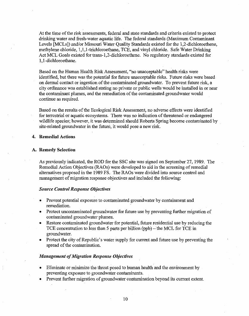
Pump and Treat System
Progress on this issue is satisfactory. The effectiveness of the pump and treat system iscontinually evaluated, and steps are taken when necessary to ensure the system will continueto operate properly and successfully. Chemical and hydraulic data are routinely collected.The data are evaluated as part of the ongoing system evaluation. Other significant activityincludes:
• Continued removal ofTCE from the groundwater with a general downward trend in TCEconcentrations in most of the extraction and monitoring wells. The total estimated TCEremoved over the last five years has been 8.8 gallons, for a total of 64.2 gallons since thebeginning ofthe RA.
• A packer test was performed on CW-1, and it found contaminated groundwater from theshallow aquifer is entering the well from the base of the casing. The packer has remainedin place to prevent further TCE from entering the DBR from the shallow aquifer.
• The remedy has consistently methydraulic performance criteria as outlined in theCD/SOW.
• The system has been well maintained with components replaced or repaired as needed.• Quarterly and annual reports are submitted on time and provide a comprehensive
sunnnary ofthe data collected and the activities that have taken place over the reportingperiod.
Horizontal Well in the Unconsolidated/Fractured Shallow Bedrock
Progress on this issue is satisfactory. In addition to the short-term tests that were completed,a one-year pilot test was executed. The one-year pilot project was executed from December2001 through December 2002. Based on the results of the pilot project and the subsequentapproval of an ESD to the ROD in 2004, the horizontal well was approved for continued use.On June 30, 2003, MRAC received approval from DNR to begin full-time use of the horizontalwell as part of the remedy. Since that time, MRAC has discharged approximately four milliongallons of treated groundwater to the horizontal well reducing sanitary sewer discharge costs bynearly $23,000.
B. Other Issues Identified During the Previous Five-Year Review
Incorrect Area Code on Site Signs - This error has been corrected. Progress on this issue issatisfactory.
Site Legal Description as Found in the Missouri Registry - This issue has been addressed.Progress on this issue is satisfactory.
15

6. FIVE-YEAR REVIEW PROCESS
A. Administrative Components
This FYR was completed through combined efforts of the Agencies, USACE, city ofRepublic, and the operating contractor. USACE was designated as the primary author of theFYR with approval and comment by the Agencies.
The review schedule included the following components:
• Community Involvement (none solicited, see section B)• Document Review• Data Review• Site Inspection• Local Interviews (operating contractor)• FYR Report Development and Review
The review schedule will provide for approval of the third FYR by the scheduled suspensedate of September 2007.
C. Community Involvement
A public notice was printed in the Republic Monitor newspaper for community notificationon March 28, 2007. In addition, a fact sheet was developed for the SSC site. Both areincluded in Attachment G.
Upon finalization of this FYR, a notice announcing completion ofthe FYR will be placed inthe Republic Monitor newspaper. The notice will provide information similar to the initialnotice and will add information on the location of the FYR for public viewing (i.e., theInformation Repository).
D. Document Review
Historical documents (including the RI, Baseline Risk Assessment [BLRA], ROD, ESD, andthe CD/SOW) were reviewed as part ofthe FYR. These documents provided informationnecessary to the development of an understanding of the SSC site and application of the FYRprocess. Annual reports associated with the period ofreview were also reviewed. A listingofrelevant documents used during this FYR is provided in Attachment F.
E. Data Review
As required by the CD/SOW, the SSC site is required to submit quarterly hydraulicperformance reports and annual reports summarizing chemical and hydraulic monitoring datacollected during the year. The annual reports were reviewed to determine compliance withperformance requirements identified in the CD/SOW, assess progress in attaining the
16

remedial goals, and to determine ifthere were any issues that would call into question theprotectiveness of the remedy.
Below is a summary of findings from the review:
• Hydraulic performance criteria defined in the CD/SOW have been satisfied for all threehydrogeologic systems.
• Downtime performance criteria have been satisfied for all three hydrogeologic systems.• The TCE concentration has been below 200 micrograms per liter (~glL) for all sewer
discharges (per city and ROD requirements).• Discharge rate to the sewer has been maintained below 200 gpm (per requirements).• TCE concentrations of the effluent from the treatment system have been consistently
below reporting limits which have ranged from 1 to 5 ~g1L (per requirements).• Since the beginning of the RA, an estimated 64 gallons ofTCE have been recovered.• Extraction well SSC-30 pumping rates required to meet the hydraulic performance
criteria have increased over time. The reason for this is being investigated. One possiblecause being investigated is a leaking water supply line in the area. MRAC has reportedthis possibility to the city of Republic, but no action on the city's part has occurred todate.
Attachment C summarizes TCE results from 2002 through 2006. Figures 2 through 15 fromthe 2007 Annual Performance Report are also included to show TCE concentration trendsfrom the RI for each of the wells. Observations from the last five years of sampling resultsare as follows:
Deep Bedrock System
• With the exception of sampling conducted in February 2004 during a pumping cessationtest, TCE concentrations in samples collected from DBR extraction well REM-l haveshown a general downward trend in the last five years. In the last five years, values haveranged from 52 ~gIL to 10.6 ~g1L. The February 2004 sampling event found TCE at aconcentration of 407.0 ~g1L indicating a significant concentration rebound effect duringthe cessation test.
• TCE has not been detected above the reporting limit of 1.00 ~gIL in any samplescollected from DBR monitoring wells SSC-2B, SSC-4B, and SSC6B. The same is truefor monitoring well SSC-3B with the exception of a sample result of 1.2 ~g/L in 2005.
• TCE has not been detected in any of the active Municipal Wells CW-3, CW-4, andCW-5. CW-2 has been abandoned and closed for reasons not associated with the SSCsite.
Shallow Bedrock System
• There are no monitoring points providing data that could be used to define a cleansouthern boundary of the plume.
17

• TCE concentrations in samples collected from REM-2 increased from 1,000 Ilg/L in 2000to 6,650 Ilg/L in 2002. The latest sample from 2006 shows a concentration of 3,940Ilg/L.
• TCE concentrations in samples collected from SSC-6C spiked in 2002 to 14,700 Ilg/Lfrom the previous reading of6,730 Ilg/L. Concentrations have been on a decreasingtrend since 2002, with the 2006 reading at 7,760 Ilg/L.
• TCE has never been detected above the laboratory reporting limit (recently changed to1.00 Ilg/L) in samples collected from SBR monitoring wells to the east (SSC-lA), north(SSC-4A), and southeast (SSC-23).
• TCE concentrations in samples collected from SBR monitoring well SSC-3A (south)have shown a decreasing trend in the last five years ranging from 37.7 Ilg/L in 2002 to7.6 Ilg/L in 2006, with a high of39.6 Ilg/L in 2003.
Unconsolidated/Fractured Shallow Bedrock System
• There are no monitoring points providing data that could be used to define a cleansouthern boundary of the plume.
• TCE concentrations in samples collected during the annual monitoring events fromUFSB extraction well SSC-29 have remained relatively constant, fluctuating between1,730 Ilg/L to 1,360 Ilg/L.
• TCE concentrations in samples collected during the annual monitoring events fromUFSB extraction well SSC-30 have been on a downward trend since 2002, with a high of625 Ilg/L in 2002 to a low of 41.6 Ilg/L in 2006. Wells in this system may be directlyinfluenced by recharge from precipitation events and/or infiltration from a water supplyline in the area that may be leaking.
• Some of the treated plant effluent is discharged to the horizontal well in lieu of dischargeto the sewer. TCE concentrations in discharged, treated groundwater are below thereporting limit of 1.00 Ilg/L. Therefore, TCE concentrations in fluid discharged to thehorizontal well are below the reporting limit of 1.00 Ilg/L.
• TCE concentrations in samples collected from the UFSB extraction well SSC-31 haveexhibited a decrease from a high of 30.6 Ilg/L in 2002 to a low of 1.9 Ilg/L in 2005. TheTCE concentration for 2006 was 10 Ilg/L.
• TCE concentrations in samples collected from UFSB monitoring well SSC-ll have beenvariable in the last five years with a TCE concentration of 336 Ilg/L in 2002, 1,260 Ilg/Lin 2004, and back down to 944 Ilg/L in 2006.
• TCE concentrations in samples collected from UFSB monitoring well SSC-20 have beenvariable but have been on a general downward trend since 2002. In 2006, the TCEconcentration was 5,770 Ilg/L. Reduction in TCE concentrations in this well appearsslow given the close proximity and similar screen depth to extraction well SSC-30.
• TCE concentrations in samples collected from UFSB monitoring well SSC-24 haveremained relatively stable over the last five years. The TCE concentration was 1,020Ilg/L in 2002 and 1,050 Ilg/L in 2006, with a low of 453 Ilg/L in 2005. This well islocated very close to extraction well SSC-30 but has a screen depth 40 feet below that ofextraction well SSC-30. The stable concentration in this well may be an indicator
18

groundwater monitored by SSC-24 (deeper portions of the UFSB) is not currently beingcaptured by extraction well SSC-30.
• TCE concentrations in samples collected from UFSB monitoring well SSC-26 exhibiteda general decrease ranging from a high of33.1 f..tg/L to a low of7.0 f..tg/L.
• Monitoring well SSC-27 was dry from 2002 through 2004 so no samples were collected.In 2005, the sample was below the reporting limit of 1.00 f..tg/L; and in 2006, the TCEconcentration was 1.3 f..tg/L.
• TCE concentrations iri monitoring well SSC-32 have shown a slightly decreasing trendover the last five years.
• TCE has never been detected in any samples collected from Roberts Spring.
F. Site Inspection
A site inspection was completed on June 4,2007. Representatives of the FYR team and siteinspection participants included the Agencies, USACE, city of Republic, a representativefrom MRAC, and the operating contractor. A list of participants is included at the end of thesite inspection checklist located in Attachment E. The inspection included the treatmentsystem, monitoring and extraction wells, Roberts Spring, and general inspection of the SSCsite proper.
The SSC site was found to be in very good condition. The exterior of the extraction andmonitoring wells appeared to be well maintained (a deeper, interior inspection was notconducted; operational data provided the necessary information). The treatment building andall treatment system components appeared well maintained and in proper working order.Equipment, piping, and valves were properly labeled; The O&M manual, design documents,and maintenance records were all readily available. Site personnel demonstrated thecapabilities of the control and monitoring system for the treatment plant. Overall thetreatment system was found to be in good operating condition and well managed. Therewere two minor maintenance items identified:
• The labels on two ofthe flush-mounted wells were losing legibility, and no label wasreadily apparent or was identified by project personnel as extraction well SSC-30. Whilethis is not a critical issue, it is one that merits attention during general site maintenance.
• A low hanging branch extends outside the fence from a tree located within the site fence(south fence, west side). This has the potential to make site access easier for vandals.Removal of the low hanging branch should resolve this problem.
G. Interviews
Interviews were conducted during the site inspection. The operating contractor providedinformation regarding O&M ofthe existing pump and treat system, implemented andlorplanned system upgrades or opportunities for optimization, and identified critical aspects ofsystem operation that may require attention prior to the next FYR. Any substantive issuesidentified during the interview are discussed further in Section 7.
19

7. Technical Assessment
Question A: Is the remedy functioning as intended by the decision documents?
Yes.
While the remedy is meeting the performance requirements outlined in the CD/SOW, there aresome issues that may require further evaluation to ensure the protectiveness of the SSC site.These issues are discussed in this section; and issues and recommendations are summarized inSections 7 and 8, respectively.
RemedialAction Performance
The RA continues to be operated as designed and is functioning properly. The system continuesto operate within established design parameters and has achieved a downtime performanceduring the last five years that is consistent with and/or better than the established criteria.Hydraulic performance criteria (drawdown and rolling average annual levels) established in theCD/SOW or modifications approved by the Agencies have been satisfied for all threehydrogeologic units, and the sewer discharge limits have been met.
The original estimate for remedy completion was a 40-year RA schedule. Based on the analysisprovided in the Five-Year Performance Report completed in 2006, the RA is proceeding asexpected and contaminant concentrations within groundwater are being reduced. According tothe Five-Year Performance Report prepared by MRAC in 2006, long-term trending indicates theprogress toward achievement of remediation goals is ahead of schedule.
System Operations/Operation & Maintenance
The operating procedures as implemented continue to provide for an effective response action.An increase in RA maintenance costs has resulted from the need to replace equipment that hadreached the end of serviceable life. These activities are normal and are not in this case indicativeof poor maintenance or aggressive deterioration of materials. The increase in costs as a result ofthese activities does not indicate a problem with system operations or O&M.
Opportunities for Optimization
Optimization efforts (horizontal well) have been conducted at the SSC site. Severalopportunities for optimization are currently under review and will be implemented asappropriate. As an example, daughter products resulting from the degradation of TCE have beendetected in the extraction wells in each of the hydrologic units and in a few of the monitoringwells in the UFSB unit. The detection of cis-l ,2-DCE and vinyl chloride suggests biodegradationis occurring at the SSC site. An evaluation of this process and possible implementation of anenhanced bioremediation program at the SSC site may prove beneficial at reducing the timerequired to meet the RAOs.
20

Early Indicators ofPotential Issues
Increased Pumping Rate at Extraction Well SSC-30
There has been an increase in the pumping rate required to maintain the required drawdown inextraction well SSC-30. Although a specific cause has not been identified with certainty, it issuspected it may be due to a leaking water supply line in the area. If this is the cause, anassessment of the impact on remedy performance and O&M should be conducted. Anysubstantive change in the system that results from artificial or natural influence should beevaluated to determine whether baseline operating assumptions are still valid.
The TCE concentration provided by extraction well SSC-30 has noticeably decreased in the lastfew years. Although there is a possibility this could be the natural progression of the remedy ascontaminant concentr;ttions decrease, it is possible a source ofclean water (either natural orartificial) is being introduced into the system diluting the water extracted and potentiallychanging the hydraulics of the system. The resultant increased pumping rate also increasesoperation costs (treatment and disposal).
Change in Pump Intake Elevation in Extraction Well SSC-30
Extraction well SSC-30 was originally constructed for a pump elevation of approximately 1,224feet above mean sea level (or 80 feet bgs). However, due to sediment infilling of the borehole(siltation), the pump intake was set at approximately 24 feet bgs. This change in the pump intake
, elevation may reduce the effectiveness of this well at removing contaminants particularly in thelower portion of the UFSB. This does not represent a short-term protectiveness issue but mayimpact long-term protectiveness if the system is not able to meet remedial goals in the prescribedtime frame.
Limits of Plume in SBR and UFSB
The limits ofthe plume in the SBR and UFSB are not fully defined using the existing monitoringwell network and available data. Monitoring well SSC-3A is the southern-most well installed inthe SBR and had a TCE concentration greater than 200 flg/l at the time of installation. In theUFSB, the southern-most monitoring wells are SSC-26 and SSC-27. When installed, SSC-26and SSC-27 had TCE concentrations in the range of 75 flg/l and 260 flg/l, respectively.Although the remedy appears to be effective at reducing the TCE concentrations in the vicinityof these wells, it is uncertain how far south the plumes extend and how protectiveness isimpacted.
Implementation ofInstitutional Controls and Other Measures
Section 710.150 of the Republic City Code prohibits construction of wells, cisterns, or facilitiesfor the production of groundwater. Construction of new wells, cisterns, or facilities is allowedonly for the purpose of groundwater remediation or monitoring within the area as defined by thefollowing streets: Anderson Street, West Avenue, Miller Road, and Hampton Avenue. This
21

ordnance prevents future use of groundwater so the exposure pathway associated with householdand potable uses remains incomplete.
Controls such as fencing, warning signs, and well locks are in place. These controls preventcasual access to the treatment facility and other components of the RA. Access to extractedgroundwater is restricted to authorized plant operators and other personnel. Although thesecontrols are in good condition, there is a large tree within the site fence with a low hangingbranch extending outside the fence. This simplifies access to the SSC site by vandals.Removing the low hanging braIlch would eliminate this problem. No other actions appearnecessary.
Question B: Are the exposure assumptions, toxicity data, cleanup levels, and RAOs used at thetime ofthe remedy still valid?
Yes.
Changes in Standards and To Be Considered(s)
Chemical-specific ARARs and To Be Considered(s) [TBC(s)] were identified in Appendix A ofthe ROD and included: Federal 40 CFR 141 (safe drinking water standards), Missouri 10 CSR60.4 (drinking water standards), Missouri 10 CSR 20.7 (water quality standards); and federalambient water quality standards for aquatic life protection. These numeric criteria areestablished to protect human health from ingestion of contaminants in groundwater and surfacewater and from ingestion ofpotentially contaminated aquatic organisms. Numeric criteria alsoinclude acute and chronic ambient water quality levels for protection of aquatic life. As theremedy progresses toward restoring the three groundwater hydrologic units to unrestricted use,the same ARARs that were valid when the remedy was chosen will need to be met when thegroundwater is considered fully remediated. Note numeric values for inorganics, totalchromium, copper, lead, mercury, nickel, and zinc along with all organics detected ingroundwater during the Rl were listed in the ROD and initially identified for monitoring.However, the RD report concluded the remedial discharge fluids were insignificant componentsof the sewer system's fluids which enter the POTW, the levels measured during RD were belowthe federal and state drinking water standards, and no pretreatment of fluids from the SSC sitewas required. Eliminating inorganics from monitoring was approved by DNR in a letter datedFebruary 14, 1990. Numeric values current at the time ofthis FYR have been compiled and areprovided in Table 3 (Attachment B).
Action-specific ARARs selected at the time of the remedy are still valid. Provided institutionalcontrols remain in place to prevent potable well installation in the contaminant plume andprovided the contaminant plume is being captured and not reaching a classified water body(where ambient water criteria apply), any changes in ARARs andlor TBC(s) will not impact theprotectiveness of the remedy since exposure pathways remain incomplete.
22

Changes in Exposure Pathways
There has been a recent focus nationwide on the vapor intrusion to indoor air pathway especiallyon sites with TCE contamination. Vapor intrusion can pose health concerns for occupants ofbuildings with basements, with slab-on-grade, and also with crawl spaces. EPA's draft guidancefor the vapor intrusion pathway identifies steps for screening sites that may be of concern.Among the steps are identifying sites with contaminants of sufficient volatility and toxicity,identifying sites with occupied buildings located within 100 feet vertically or horizontally ofsubsurface contamination, and comparing site data to media-specific target levels. Given thevolatility of contaminants at the SSC site, the shallow depth to the water table (approximately 10feet bgs), and the proximity of occupied buildings to the plume (included among these a daycarecenter, homes, and apartment complexes) further evaluation of this potentially completedexposure pathway is warranted. TCE concentrations in the UFSB groundwater wells ranged upto 5,950 ftg/L (compared to a 5 ftg/L target screening level set to protect to a target lE-06 cancerrisk).
While there have been no changes in the SSC site conditions that create new exposure pathways,a daycare center is now located immediately north ofthe treatment building across East ElmStreet. This brings a sensitive receptor population near the SSC site and creates a potential foroutdoor air exposure. An evaluation of the discharge height for the air stripper was completed todetermine if there is a potential for impacting the center. To ensure VOC emissions fromgroundwater treatment will not result in an exposure pathway at the daycare center, the treatmentfacility now only pumps the most contaminated wells at night. The nightly pumping is sufficientto maintain the requirements set forth in the CD/SOW.
The daycare center, while located upgradient of the plume, is in close proximity horizontally ofsubsurface contamination. An evaluation into the vapor intrusion to indoor air pathway iswarranted.
No new exposure pathways for ecological receptors were identified for this FYR.
Changes in Toxicity and Other Contaminant Characteristics
Several toxicity factors have changed since the time the BLRA was conducted. Of significanceis the fact there are now inhalation toxicity values for evaluating cancer and noncancer adversehealth effects that were not previously available. Most important of the new information are thetoxicity data compiled as part of the reassessment ofTCE toxicity. While conclusions made inthe reassessment are still under review, research studies do indicate TCE toxicity is greater thanpreviously thought through both oral and inhalation routes of exposure. The final assessment ofTCE is expected soon.
The newly available inhalation toxicity factors coupled with the recent focus on vapor intrusionto indoor air pathway warrant confirming the protectiveness of the remedy.
23

Changes in Risk Assessment Methods
The BLRA for the Rl was conducted under the SuperfimdPublic Health Evaluation Manual(SPHEM) (EPA 1986). The current practice is to use the Risk Assessment Guidance forSuperfund (RAGS) (EPA 1989). While much of the methodology is the same, the process forselecting chemicals to be evaluated in the BLRA is somewhat varied. Selection of indicatorchemicals under the old guidance tended to be more arbitrary, and more chemicals could beeliminated than under the methodology described in RAGS for selecting COPCs. However, theremedy is desigued to address all VOCs and not just indicator VOCs. This plus the requirementall VOCs must meet ARARs make the impact of this change in methodology inconsequential.Receptor populations, contact media, exposure pathways, and assumptions remain valid today.
While EPA has issued new guidance for conducting ecological risk assessments since the BLRAwas written, the initial step of the ecological evaluation process remains the same. Underproblem formulation, the likelihood of exposure pathways is evaluated. The BLRA concludedexposure opportunity and the potential for ecological risk at the SSC site were minimal.Continued urbanization in the area renders the SSC site an unattractive habitat. Roberts Spring isa downgradient surface water body identified as being in hydraulic connection with thegroundwater system at the SSC site. If the plume was to migrate to Roberts Spring, there may bea need to evaluate the impact to ecological receptors. However, samples at Roberts Springcontinue to be nondetect. In addition, ambient water quality criteria have been identified astargets for this location thereby ensuring protection to aquatic organisms.
Expected Progress Toward RemedialAction Objectives
In September 2006, MRAC submitted the third Five-Year Performance Report. In this report, itis estimated the RA is greater than 85 percent complete. It also anticipated groundwater cleanuplevels will be met within approximately IS years.
Question C: Has any other information come to light that could call into question theprotectiveness of the remedy?
No.
No ecological targets were identified during the BLRA, and none were identified during theFYR; therefore, monitoring of ecological targets is not necessary. Even though this monitoringis not necessary, annual VOC sampling, especially of TCE, is recommended at Roberts Spring.No weather-related events have affected the protectiveness of the remedy. There is no otherinformation that calls into question the protectiveness of the remedy.
24

8. ISSUES
CurrentlyAffects Future
IssueAffects
ProtectivenessDescription Protectiveness
(YIN) (YIN)
I Siltation of extraction well SSC-30 N Y
2Potential leak in water supply line in the vicinity
N yof extraction well SSC-30Confirmation of appropriate coverage by theinstitutional controls designed to protect against
3 exposure to contaminated groundwater; * *Delineation ofTCE at or below the MCL in theUFSBand SBR
4 Vapor Intrusion Pathway * *.
*Potential to affect protectiveness; more information must be collected and analyzed prior tomaking a final determination.
25

9. RECOMMENDATIONS AND FOLLOW-UP ACTIONS
Recommendations/ Responsible Oversight Milestone AffectsIssue Follow-Up Actions Party Agency Date Protectiveness
(YIN)Current Future
Determine the impact of siltationon remedy performance andeffectiveness. Potential
Septembersolutions include but are not MRAC DNR
1limited to: install a new well EPA
2008 N y
with deeper pump intake, installa new casing, and screen insidethe existing well.Assess the impact of theleaking/potentially leaking waterline in the vicinity of extractionwell SSC-30; provide an
2evaluation in terms of remedy,
MRACDNR
September N yperformance, and effectiveness; EPA
2008and provide recommendationsfor mitigating or eliminatingancillary issues stemming fromthe water line leak.Determine the most effectivemeans for confirmingappropriateness of theinstitutional control coveragearea; possible paths include but
DNR September3 are not limited to new MRAC N Y
monitoring wells to enhanceEPA 2008
plume delineation, downgradientprivate well survey, and generalincrease in institutional controlcoverage area.Continue evaluation of the vaporintrusion exposure pathway;
4possible paths include but are
MRACDNR September
N ynot limited to soil gas samples, EPA 2008indoor air monitoring, plumedelineation, and modeling.
26

10. PROTECTIVENESS STATEMENTS
Based upon the available data, the assessment ofthis FYR found the remedy is expected to beprotective of human health and·the environment upon attainment of groundwater cleanupstandards. Currently, all threats at the SSC site have been addressed through hydraulic andinstitutional controls of the groundwater contamination.
Vapor intrusion exposure pathway
There has been a recent refocus nationwide on the vapor intrusion to indoor air pathway. This isespecially true for sites with TCE contamination. This issue was considered during the RI butwas not found to be a problem. However, for several reasons MRAC is currently collecting soilvapor data.
Plume delineation in the SBR and UFSB
The nature of contaminant transport in the UFSB and monitoring points in the SBR and UFSBavailable for analysis limit the certainty of plume delineation. While the existing extraction wellnetwork was designed to capture contamination and maintain or reduce the plume limits, the dataavailable to demonstrate this effect do not fully provide certainty in regard to protectionassociated with the existing in~titutional controls. An assessment of potential exposure points(i.e., private wells) outside the limits of the well restriction institutional control may providesufficient data to demonstrate current protectiveness. It may also help in determining if anyadjustments to the institutional controls are necessary to ensure future protectiveness.
11. NEXT REVIEW
The next FYR will be due in September 2012.
The trigger date for the due date of the next FYR is the approval of this FYR by EPAdemonstrated by signature.
27

Attachment A
FIGURES
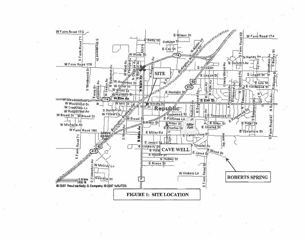
ROBERTS SPRING
W Farm Road 174 ._1...L-'-~ <j) I I~,~ ~L.- E Wilson St ,y~~",,5r:p r
'" jA I erry 51] ,r----J .,,;.;'" "'" I<t I ~ Cottage RI---l " x?~ ' '"E ~ III [o,-r "''1":,] r:.-"') v>~. q.fY '" W Farm RDad 174
.. " _,/ I ITT L I",r/" " "'"' ~ _ W 1" :;; E ij:')' 9' L irH'h'l" J ;'" <> ~"deSt +' ,,,~>' y ~
•• , "1m RO~d 178 " ,;;: '~1> .. ~~74-Lfti' ,,/ );I~_ ,~ .. .;: <i: ~P'1~ - ¥'""---=~ ~1 -c; -i: 'I;; I.e- ",!,. ~~ 1 M ~h: <j)~ __et+
IL
' c::.l::r 1:;1 I fJ>;;>if ..,\.........."'" ,,"""" ",?,," "r ' J'I -:it Ef --£.;~"-/~O.. E ~,,,f,,, V~I I .i' 'E Sum~ltAV 1'~ ""' I", . • _ >"0' • SITE ,of-" """1'" .,,'.•• , <' w A""'~" ! ,,' " -" 0
• " ,, . ,l"";"-'-' ~.",. ro , , • 00,,""-. •;;1V;~-'::~/"ir.nIS!--+-% 4,,,2 ~ ," <l~"'::"":i ----i ~'f~.. c\' • •.....,.. .'"/ ",:k a~ '. '" ,,~_., •••'"~~ ", WE""" ! ,- , ",,",,, " I,J I,~, • ~-~ ~,,_::-~ <1, OQul.pd D, z rm- _ ,," f - '/~ «; .:J ~J '-~OJ["" "'IT _~~':J'
W ,,_r-,. ,".m"" o' _'---' • ,£'" ' '~d -..' ,"'"'oN B WRid~st Av S 1>JJ,~~'5fEI ~flll SIB{OOUfA.!j f£1l7*'=:rnonillrk-siY'>-----a: - J jill '7.\"-" a'I
road"tF ,.,l<>.LI..,~?" rr~R- .. ,- "'n ' ,w I ,'" >~<,.","'I-T
W'"'''' w~~",,/M .P"""C-' g ~=--" ~ '> W--, , >~.", -%'~ • _. z I • • _--"''i
W Mlo!'.!!,le Av I II '~'c;~r~; ~."..,,'J, ~I NI I JIfv~r~ "'IW,,, " I r> ",""" ,,,•.• ,"" >"".-., " J .~', "Im ,o,~ ISa I I <t,;'if';'.'" -;!:. ,. ,---' Ritter St r---T' ,<.o+~' '~i"'i '"_ ......'_' ~ . _./ oj" .) " '~r---rr",,",,;;:e'i'dl ,"",,,,, ~·"i '( -\"",,,..'j;;' 'jE'RitterJ, ii 1
'" l;:;,1': vr <j) ::!1l ···1 I-'- rTl1"; I if " In. t 1E-Va\~e:y-View~St_ » E c~oJ.ri,d, St ~, • oo, . ". '" " L m-! 7~' . rl • "~ " '" f:( eT""'"""~L :\:".'"11 I~! ~
"' . ~.."flfJ 'i. ~I:H.I~ CAVE WELL ~i,uyl.,f'" l.;t'·,,_j£/ . /'" "' /'" E-H~ ,J-'il' .'f./ ./ .al I; J {i L'lI .
,.,;oil" ;;; WM.IO~~\ , F 'E',R,iSliYSt -P-:,dl1sf--·~l:9'.~1,{jfJ' ~b;l~_n E GI.oe St - . I,,0//" I 1 .r' . ~
,'" :"h "'@ 110,5 i<m ~ f)aoierr ;;1il2007R 1500fl <j), ,iejrrelSI p WHickoryLll "
andlkNall &c I I ""y """,""y 1il2jlll7 NAvrEQ E"'"'<j)
I FIGURE 1: SITE LOCATION I

FIGURE 2. GEOLOGIC CROSS SECTION
UNCONSOUDAlFO RE$lDlJU!>lAPPRQXlt'ATE
TOP OF~':::'_="
200' ..
:l00'
~2(1O' -.'._•• ' •• 'n"._""•••••~ ..~_. " •••~ •.•••~ •••••__ •• "._._ ••• __ •• ,_•• _ ,_ u'.n•••• ••• " •• ______ •• ___•.___.-. ••.____~ , •••••• ____ ,_. .. _ ..... ~._-- . -,,, _.. .... _..__. _-.-.._.- ...- ..-_.
-~.-.SPRJNGmU)?lJ\i'"EAiJ I'IQiJ!fER
';"11 :1 I~1°Ot~i1l,,,,,",,: -".
OZARK
lc.xr ,,-~'".._-...
TCONFiNINGUNIT
~
~'iOO'
~
tii
f! &:>0'
~
'i!~ )(X)'-
~ "II ,~IOl,.<\RK
a; €!:I)'- ... " AQUiFERz0
~
~ 500"

eN-'
R8'lf.1
ssese
To NearestSewarManhoie
Vent Vent
REM-'
Sse-3A
SSC-29
sse-so
I S~31 hTo sewer
""'he.
fI- -- II
Flow Equalization TankFeed Pump
PAS-1
BlowerBAS-1
Stripper TowerAS-1
Feed PumpPAS-2
BlowerBAS-2
Stripper TowerAS-2
Sewer Manhole
To Replblic POTW
Figure 3 - Schematic of Pump and Treat System

II , Ir~~~~>~lEGEND • MW-7".. UFS8 waJ. LOCATIONS
~SC-4A8 DBR waL lOCATIONS
A SBR WELllOCAUONS
tltItt---w- ..
MW-3 SSC-9HW-N
SSC 68 / SSC 6C ElM STREETMW-Z .. !'-- "-'s -
~l::1' i..----MW- 1SSC-29 G-. I
V"._.. .._ ..-::J--":"REM-1
SSC-1V REM-2.
- SSC-13
HW-S""- /MW-6 SSC-ZB -E
SSC-14 '\lw-s MlU.STREET
MW-4...
SSC-3Z'"CW-l
j SSC-12SSC-20 _SSC 28
SSC-24
\(~SSC-3A \ DSSC-30/SSC-1S
SSC- 38 SSC-23
S C-21
SSC-16 SSC 18 BROOKSSnerI
!j
.. SSC-17
I'~BROAD STREET SSC-2ooc 2S/- - SSC-31SSG-19
~ ~G"",·,f}l
/'OiE<XEDBY: SCALE(FfEl) sm WEll NElWORKM. KENWORTHY 0 82 164 328 • ""W.IlATf1B'<8D FIGUREE.WJ. # 6018SP ~.- i
5l'Rl'MGfIaD, MO 6S807FORMER saUD 5rATE CJRCiJITS SITE [!]f'tt.(4r1.l800-9500
DRAWN BY: MEK •• fA1{:(417)8ZM6S9 108S. MAIN STREETAUG. 29, 2006 APPROXIMAlE WORKS INC. REPUsuc, MISSOUfU

Attachment B
ADDITIONAL TABLES

TABLE 3: NUMERIC VALUES FOR CHEMICAL-SPECIFIC ARARS (current as of July 2007)
NATIONAL WATERQUALITY CRITERIA
NATIONAL Human HealthDRINKING STATE OF MISSOURI WATER Consumption
WATER QUALITY STANDARDSSTANDARDS Water Organism
Organic and
Contaminants MCL MCLG MCL AQL HHF DWS GRW Organism Only
mgfL mgfL mgfL ugfL ugfL ugfL ugfL ugfL ugfL
Acrolein 780 320 320 198 390
Benzene 0.005 0 0.005 71 5 5 2.2 51
Bis(2-ethylhexyl) 5.9 6 6 1.2 2.2phthalate
Butyl Benzyl 5200 3000 3000 1500 1900PhthalateChlorobenzene 0.1 0.1 21000 100 100 130 1600
ChloroetheneChloroform 0.1 5.7 470
1,1-Dichloroethane 0.38 37
1,1-Dichloroethene 0.007 0.007 0.007 3.2 7 7 330 7100
1,2-Dichloroethane 0.005 0 0.005 99 5 5 0.38 37
cis 1,2-0.07 0.07 0.07 70 70
Dichloroethylene
trans 1,2-0.1 0.1 0.1 140000 100 100 140 10000
Dichloroethylene
1,2-Dichloropropane 0.005 0 0.005 0.5 151,3- .
0.34 21Dichloropropylene
Ethylbenzene 0.7 0.7 0.7 320 700 700 530 2100
Isophorone 2600 36 36
Methyl Chloride 470 5 5
Methylene Chloride 1600 4.7 4.7
Phenol 100 100 300 4.6 590
Tetrachloroethane 0.005 0 0.005 8.85 0.8 0.8 0.69 3.3
Toluene 1 1 1 200000 1000 1000 1300 15000
1,1,1- 0.2 0.2 0.2 200 200TrichloroethaneTrichloroethene 0.005 0 0.005 80 5 5 2.5 30
1,1,2- 0.005 0.003 42 5 5 0.59 16TrichloroethaneVinyl Chloride 0.002 0 0.002 525 2 100 0.025 2.4
Note there were neither national nor state SMCls available for the listed organics.There were no national freshwater ambient water quality criteria for aquatic life available for the listed organics.Numerical values for inorganics were not updated since monitoring was determined to not be required.
AQL =Protection of Aquatic Life MCl =Maximum Contaminant levelARAR =Applicable or Relevant and Appropriate MCLG = Maximum Contaminant Level GoalDWS =Drinking Water Supply mgfL =Milligrams per Liter
GRW =Groundwater SMCL = Secondary Maximum Contaminant levelHHF = Human Health Protection, Fish Consumption ug/l = Micrograms per liter

TABLE 4: NONCANCER TOXICITY INFORMATION COMPARISON
VALUES USED IN 1989 VALUES AVAILABLE IN 2007
Reference Doses Reference Doses
Chemical Oral ReI. InhalationRef. Oral ReI.
InhalationRef.(mg/kg/day) (mg/kg/day) (mg/kg/day) (mg/kg/day)
1,1-1.2E-01 NCEA 1.38E-01 IRIS 1.0E-01 HEAST 1.4E-01 HEASTDichloroethane
1,1-Health
9.0E-01 Effects - 5.0E-02 IRIS 5.7E-02 IRISDichloroethenePub!.
Trans-1,2-1.0E-02 NCEA - 2.0E-02 IRIS 2.0E-02 R to ROichloroethene
MethyleneHealth
6.0E-02 Effects - 6.0E-02 IRIS 8.6E-01 HEASTChloride Pub!.
1,1,1- 9.0E-02 Health 3.0E-01 SPHEM 2.8E-01 NCEA 6.3E-01 PPRTVTrichloroethane Advisory
Trichloroethene 7.4E-03 HEAST - - CalEPA 1.7E-01 CalEPA
Trichloroethene 4.0E-01 NCEA 1.0E-02 NCEA
Vinyl Chloride 1.3E-01Health - 3.0E-03 IRIS 2.9E-02 IRISAdvisory
CalEPA = California Environmental Protection Agency NCEA = National Center for Environmental Assessments
HEAST = Health Effects Assessment Summary Tables PPRTV = Provisonal Peer Reviewed Toxicity Values
IRIS = Integrated Risk Inlonmation System R to R = Route to route extrapolation

TABLE 5: CANCER TOXICITY INFORMATION COMPARISON
VALUES USED IN 1989 VALUES AVAILABLE IN 2007
EPA Cancer Slope Factors Cancer Slope Factors
Weight of Oral OralChemical Evidence(mglk.~lday) Ref. Inhalation Ref. Ref. Inhalation Ref.(mglkglday)"' (mg/kg/dayr1 (mg/kglday)"'
1,1- C 9.10E-02HEAST, - 9.10E-02 IRIS 9.10E-02 IRISDichloroethane NCEA
1,1-C 6.00E-01 IRIS 1.2 IRIS - -Dichloroethene
MethyleneB2 7.50E-03 IRIS 1.42E-02 7.50E-03 IRIS 1.60E-03 IRIS
Chloride
HEAST,SPHEM,
Trichloroethene B2 1.10E-02 IRIS 4.60E-03 Health 1.30E-02 CalEPA 7.00E-03 CaiEPAEffectsPub!.
Trichloroethene 4.00E-01 NCEA 4.00E-01 NCEA
SPHEM,HEAST,
Health SPHEM,Vinyl Chioride A 2.3
Effects1.50E+00 Health 3.10E-02 iRIS 3.10E-02 IRIS
Pub!.EffectsPub!.
CalEPA = California Environmental Protection Agency NCEA = National Center Environmental AssessmentHEAST =Health Effects Assessment Summary Table SPHEM =Superfund Pubiic Health Effects ManualIRIS =Integrated Risk Infomnation System
Attachment C
SUMMARY OF TCE DATA FROM LAST FIVE YEARSAND
TCE TREND PLOTS

Summary of TCE Results iu Last Five Years: 2002 to 2006
RA Monitoring Network Auuual TCE Results (uldL)Location Sample Location 2002 2003 2004 2005 2006DBR Post-ClosureMonitoring CW-l 1.8J 3.5 5.9 (1.00) 2.14DBR Remedial Extractiou REM-l 52 36.2 27 10.6 23.2
SSC-2B (1.00) (1.00) (1.00) (1.00) (1.00)
DBR MonitoriugSSC-3B (1.00) (1.00) (1.00) 1.17 (1.00)SSC-4B (1.00) (1.00) (1.00) (1.00) (1.00)SSC-6B (1.00) (1.00) (1.00) (1.00) (1.00)CW-2
Muuicipal WellsCW-3 (1.00) (1.00) (1.00) (1.00) (1.00)CW-4 (1.00) (1.00) (1.00) (1.00) (1.00)CW-5 (1.00) (1.00) (1.00) (1.00) (1.00)
SBR Remedial ExtractiouREM-2 6650 4600 5350 4850 3940SSC-6C 14700 9840 9120 6490 7760SSC-IA (1.00) (1.00) (1.00) (1.00) (1.00)
SBR MonitoriugSSC-3A 37.7 39.6 29.5 17.4 7.56SSC-4A (1.00) (1.00) (1.00) (1.00) (1.00)SSC-23 (1.00) 0.70J (1.00) (1.00) (1.00)SSC-29 1650 1450 1640 1730 1360
UFSB Remedial Extraction SSC-30 625 194 271 126 41.6SSC-31 30.6 20.9 22.9 1.86 10SSC-ll 336 963 1260 702 944SSC-20 8050 13400 8550 4160 5770SSC-24 1020 905 1230 453 1050
UFSB Mouitoriug SSC-26 33.1 19.3 21.3 6.95 7.75SSC-27 (1.00) 1.31Roberts Spring (1.00) (1.00) (1.00) (1.00) (1.00)SSC-32 326 251 268 243 239
( 1.00) - parenthesis denotes TCE not detected above reporting limit

V,/
VV
V./
//'
1<)
...... ::::::+
""'"
(")
$(J)
"coMonthQ:
~ 11187::u 2188(J) 5/88"0 8/88iil- 11/88Ki 21890 5/890
'" 8/890 11/89...
2190§: 5190'< 8/90I 11/90'< 21910-il 5191£ 8/910' 11/91ll) 2192"0- 5/92» 8/92"" 11/92co 2193!l!.(") 5/93::; 8193(J) 111933 21940'!l!. 5/94::u 8/94
" 11194
'" 2195"'11",' 5/95co 8/95ill"' 11/95
'" 2196~
'" 5/96X ;s: 8/96r 0 11/96(j) :::I- 2197::r 5/97
~ 8/97.. 11/97~ 2198
5/988/98
11/9821995/998/99
11/9921005/008/00
11/0021015/018/01
11/0121025/028102
11/0221035/038103
1110321045/048104
11/0421055/058105
11/052106
"'11 5/06• 8106'" 11106
o g § ~TeE (ug/L)
g 8 Qo 0 ~ § § § §
-Io
(J)m
2.0_. 0c.~(J)(')
s:_CD::ua~» CD q(')Oa
c.... ::tJ -- -.III (I) "" 0::::l (')lii -g c ~ .".:;;: 5l: ;::;: -I G)~]i":' ~ c:.s:~~;:oN-.(') c.mOUI':::::~(J):rN
l: C:1. "C CCJ) CD aJS'~:::o
§ :Ec.!.(J)_. :::0(jjm
3:I~

~~
~...~
~
lS
. ~
>. ~•
:~:::.
~
~
I
o~"0eQ:
~"0o
~oo
'"52j~OJSirIII
1l.S-O>e!'!.o
~[
~<fie
~~
'"Xfii
."
•w
Month11/87
2/885/888/88
11/882/895/898/89
11/892/905/908/90
11/902/915/918/91
11/912/925/928/92
11/922/935/938/93
11/932/945/948/94
11/942/955/95
is: 8/95g 11/95:; 2/96=< 5/96C1l 8/96~ 11/96
2/975/978/97
11/972/985/988/98
11/982/995/998/99
11/992/005/008/00
11/002/015/018/01
11/012/025/028/02
11/022/035/038/03
11/032/045/048/04
11/042/055/058/05
11/05
o i'! ~ gTeE (ug/L)gs g N t m ro
-I
cn Oo m=0Q.O
cn~s:S'(1);:o_::::J» (1) ooiil
c- "'" _ .......Q,) AI., -.::1(00 0&i]c::::J!!-< 5!: ;::;: -I G><,.>0·:' ~ c.:-'" i:::::J ::::J :;aN_.O""m0 0 - ~olJlC/)_W--J 0 ::::J
c: C:I. "C Cen (1) ...._ .... \AI
fii2'::tJ::::J ~Q.(1)C/)=;::;:0(1) ~
I~

dCJ)m
2,0_. 0Q..:::sCJ)(')
:;:S'CD;o_:::s» CD ::t(')0 a
e..- ;:;tJ -- --III (J) "'I 0:::l (')lii -g c :::s 'TI
.:.< 2: ;:::;: -t C5w('j':' a c:~-. :;::::s :::s ::0N-'(') Q..m0(11-~g:CJ)5'~
c c::!. '0 00en CD OJia'::::t,:;;O
c ~:::s CDQ..-00_. :;;0S'm
SN
g~§§TeE (ug/L)
~~~§oMonti
11/82185/88/8
11/82185/88/8'
11/82195/98/91
11/92195/98/9
11/92195/98/9
11/92/95/98/9
11/92/9,5/98/9
11/92195/98/9
11/92/9
s: 5/9o 8/91;a 11/98::r 2197=< 5/97'" 8/97~ 11/97
21985/988/98
11/9821995/998/99
11/9921005/008/00
11/002/015/018/01
11/0121025/028/02
11/0221035/038/03
11/0321045/048/04
11/0421055/058/05
11/052/085/068/06
11/06
"l1....
o
~"0C
2:
~"0o
~oo<J)
2j::r:
'<§.iilcg":JQ.
5':JC91o
~ii·91-
icO·c
~~
'"xfn

TeE (ug/L)N ~ ill ill ,; " ~ ;;;0 0 0 0 0 0 0 00 0 0 0 0 0 0 0
00 0 0 0 0 0 0 00 0 0 0 0 0 0 0
cK500..()
iii" 9/87;? 12187
3/88"U 6/88
.Q. 9/88(l) 12/88~ 3/89::;] 6/89(j)
9/89~ 12/89AI 3/90J> 6/90()
9/900;0 12190~ 3/91co'" 6/910 9/91
"0 12/91
'" 3/92"0- 6/92;;:: 9/92
'" 12/92~ 3/930 6/93~
AI 9/93(l) 12/93"0c: 3/942: 6/94o·
9/94(j)12194
J 3/956/95
"0 9/950 121951if 3/96:;; s: 6/96" 0 9/96"c: g. 12/96'"iG =< 3/970 (I) 6/970
'" 9/97(»
0 ~ 12/97.. 3/98
'" 6/98" 9/980-
J> 12/98
" 3/99"c: 6/99!l!. 9/99() 12199:T
3/00(l)
3 6/00o· 9/00!l!. 12/00?i' 3/01"0 6/010
9/01~ 12/01"" 3/02c:CD 6/02
~ 9/02<5. 12/02c: 3/03CD 6/03"' 9/03'l:: 12/03
'" 3/04X 6/04r
9/04(j)
121043/056/059/05
12/053/06
" 6/06• 9/06
'" 12/06
/V
/V
./l.----~----«:...
.~
<IV,
----~~<•. I~
~
. /
~
•
-IoC/)mo 0=0Q.~
C/)gs:S'~;lJ - -» (1) ~00-
&"" ;tJ _. cr:::l(l)~~iji -g C .".., tT _. -I (j)",,-_-._. ~ (1)~!,_~c:. s:~ Q.::ON _. 0 111o (h. -o /II C/) ~ en~oE; c C/)
_.'t' OJ!!! (1) ::0lt2-:E~ (1)Q.=C/)C/);:;tJJ(1) 0
c!no

v ~
/V
:/
•.'"t>1<t>.f
~
•
0
53<l>-0c: 9/872:~ 12/87::0 3/88<l> 6/88-00 9/88iil- 12/88N 3/890 6/8900) 9/890 12/89... 31900 6/90~ 9/90I 12190'< 3/910-iiJ 6/91S 9/91o' 12/91m 3192:>0- 6/92» 9/92:> 12/92:>c: 3193E. 6/930 9/93:T<l> 12/933 3194o'E. 6/94::0 9/94
-0 12/94::> 3195.."
"r 6/95c: 9/95<il"' 12/95
" 3/96.c. 6/96'"X iii: 9/96r o 12/96(f) a 3/97
::T 6/97=< 9/97m12/97.., 3/98
6/989/98
12/9831996/999/99
12/993/006/009/00
12/0031016/019/01
12/0131026/029/02
121023/036/039/03
12/033/046/049/04
12/0431056/059/05
12/053/06
"Tl 6/06• 9/06
'" 12/06
o g: 8 § gTeE (ug/L)
g 8 i1i g ~
g: g
-I(')
C/)mo (')=:0o.:sC/)()
CDsS':s;:tl - -» CD iil()(')e.
1» ;:tl ::::;. 0:::l (l) () :s","0III l: C -I "-< 5!: ;:::;:., ,..,
_. ~ CD '"~p_:sC:. s:S 0.::0N-'() metA- -o til c/) :s en~o
:; C C_. 'tj OJ!!! CD ....lt~"'"
C :iE:s CD0.=~c/)etC/)
(')
l.J»

~
\~
~""~.~
l
~ t
,~
~
~
..
0$<!>-0C
2: 9/87§:;AJ 12/87<!> 3/88-0 6/880
~9/88
12/880 3/890
6/89a>0 9/89"'- 12/89
j 3/906/90
I 9/90'< 12/90Q. 3191iilc 6/91g: 9/91
" 12/91::l 3192Q.
» 6/92::l 9/92::l 12/92c!l!. 3/930 6/93::l" 9/93<!>3 12/930" 3/94!l!. 6/94;AJ 9/94-0
"" 12/94
" 3195<0"c 6/95iil 9/95
'" 12/95~ 3196
'" s: 6/96X o 9/96S; ;a 12196=- 3/97
=< 6/97'" 9/97~ 12/97
3/986/989/98
12/983/996/999/99
12/9931006/009/00
121003/016/019/01
12/0131026/029/02
12/023/036/039/03
12/033/046/049/04
12/043/056/059/05
12/053106
" 6/06. 9/06...12/06
o § iTeE (ug/L)
§ ~ ~ ~
-I(")m
c/)(")2.0_. ;:,0.(")en CD
s:S-;:'AI ........» CD iiJ(")(")0:
&- AI _. 0::l (I) ~ ;:,
~ -g c -I '"T1.;;::5l:::;:""l;::::_. ~ CD \II
~s~_;:,c_ S:;:' 0. ;;0N ;::. (") _ movo'o 1/1 ". ;:, .....--J 0 VI C
l: C::1. "C "en CD enit:::l. 1XJ
§ ~0. CD-en--' C/)arC/)
(")
~CD

....7
~
" j---l.--': 6C
. "
~,~ ..
•~
-
0'-'::u(D-0c2: 9/87~::u 12/87(D 3188-0 6/880
iF 9/88N 12/880 31890
6/89<J)
0 9/89... 12/89
j 31906/90
I 9/90'< 12/90"- 3191ii1So 6/910· 9/91
" 12/91:J 3192"-l> 6/92:J 9/92:J
12/92c!!1. 31930 6/93:J" 9/93(D
3 12/930· 3/94!!1. 6/94::u 9/94-0::> 12/94." 3195<is.
6/95cCil 9/95en 12/95~ 3196
'" 6/96X 9/96,...(j) s: 12/96
o 3/97:::l 6/97;: 9197=< 12/97C1l 3198~ 6/98
9/9812/98
31996/999/99
12/9931006/009/00
12/0031016/019/01
12/013/026/029/02
12/0231036/039/03
12/0331046/049/04
12/0431056/059/05
12/053106
." 6/06• 9/06
'" 12/06
o § § § §TeE (ug/L)
§ § § § § i
~en
mo 0_0_. ::::10.(")en(\)
sS'::::1;;0--» (\) ii1oO!:!:
iii ;;0 -. 0::J (\) .. ::::1~-gg-l-n
L"""!. CT - .... -I~ __ (\) (i)
~ p' "'-- ::::1 C·s::::1o.;;tJN _. (") mo en· 0 0 ",,::::100~ 0 V' Cc: C
::I. "C "!:!! (\) enet=l,OJ
§ ~o.(\)-CJ)--. en<teno
&o

()
%"-0c:2:
jo
~§o'"~'<I't§.OJEoO·ll>
"0.
?f"c:!1.()or
"3[;0
~ocrc:
~enXS;
."•
(l)
o ~
TeE (ug/L);:; ~o 0
-Ioen
m
o 0_0_. :::JQ.~enC'D
s:S":::J;:0--» C'D ~~O!:!:
c.. ;:0 _. 0§ (I) a :::J&i 1l c -I "11-< !2: ;:::;: ... ;:::_. ~ C'D '"~!l _ :::J c:_ s::::J Q. ;;0l:5 (if S'l - mo Ul ". :::J <D---I 0 v, C
s:: C:::!."C ."~ C'D enlt~lXI
§ :EQ.C'D-en-_. en<teno
IW-

- /"
//
VV
<',
~ ............~
~
\~
- ~
~
~
~
~
~
o%illc:2:
~'"o~§o...g-ZI'iiiilEoO·
""0.
S'"c:a!oor<l>3[
i<0'c:
~'"Xr.;;
."
•~
<:>
9/12/·
3/6/.9/.
12/·3/6/9/.
12/,3/96/99/9
12/93/96/99/9
12/93/96/9.9/9
12/93/96/9919
12/93/96/99/9·
12193196/99/9
12/9319
'" 619,=- 9/9g 12/9- 319". 619~ 919III 12/9""I 3/9
6199/9
12/963/9961999/99
12/99310061009100
12/00310161019101
12/013/0261029102
12/023/0361039103
12/0331046/049104
121043/0561059105
12/053/066/069106
12/06
o § ~
TeE (ug/L)
g ~ § § I
-Iom
(/)0o 0=:1Q.~(/)CD-::::J
s: $I) "-ilI» CD _
~ 0 o'c... " :::;' ::::J ."III CIl ~ -I _:::l "C C (j)lii §. ;::;: @ c-< =: ~ ::::J:::tl~P5'Q.m. s: ~ _ ....N(jj'. ::::J 0g~(/)c..... c C "
::l."C (/)en CD .....::+:::5. ...CIl C :e
::::J CDQ.--~(/)-(/)CD 0
.:...
..:.

;---
V
//
/~
.....""".
(
/';~
,
, \, t
~
~
(")
5iCD
"0<:g:~ 9/87;0 12/87CD 3188"00 6/88
~9/88
12/880 31890
'" 6/890 9/89... 12/890 3190~ 6/90I 9/90'< 12/900-
3191ill£ 6/910' 9/91III 12/91:J
31920-J> 6/92:J 9/92:J<: 12/92!!. 3193(") 6/93=r
9/93'"3 121930' 3/94!!. 6/94;0 9/94"0
'" 12/94." 3195<is'<: 6/95iil 9/95U>
12/95NC, 3196
'" ;;: 6/96Xr o 9/96(/) :::l 12196:r 3/97
=< 6/97'" 9/97e: 12/97
31986/989/98
12/9831996/999/99
12/9931006/009/00
12/0031016/019/01
12/0131026/029/02
12/0231036/039/03
121033/046/049/04
12/0431056/059/05
12/05." 3106, 6/06- 9/06- 12/06
o ~ ~ ITeE (ug/L)
I I ~ ~ I I
<im
000o 0=::::sQ..(")oo(\)-~"" III _;:'-SiJ;;a (\) _
» 0 _.(") 0'- ;;a ::;. ~ "11Ql (1) (") -1-::l 'tl C Q&i §. ;:;: @ c-<=~ ~:::a~51:;Q..m- is: (") _ ....N C;;'. ~ ....g~ooc--J l: C "
::!. "C 00en (\) ...;:;:~\N
(1) C ~~ (\)Q..--~oo-00(\) 0~o

If
<: lo...
~>< >K,
"--1\
rV
)~
V).
•~..
()
$<!>"0C!Z§:~"0o
~~o"-
~I!iiil5.,,'0>
is.?;:>c!!!.()
153[;U
~irc
~'"Xt;;
"l1
~
'"
9/8712/87
31886/889/88
12/8831896/899/89
12/8931906/909/90
12/9031916/919/91
12/9131926/929/92
12/923196/99/9
12/93196/99/9
12/93/96/99/9
12/93/9
;;: 6/9o 9/91a 12191::r 3/9~ 6/9'" 9/9... 12/9
3196191
12i'3/'6/'9/'
12/'3116/19/'
12/'3i61'9/1
12,3.6.9
12369
12369
12/13,69
12,369
12,
~ ,; '" gTeE (ug/L)
ill g g § § §
-Ioen
mo 0_0_. :::s0. 0en(\)
",,-:::S:::. ll) _
~Citii1oo:::t.
c... ;:0 _. 0(I) ~ :::s"gc-l:!!
-< !! ;:;: '"I (i)wo'~ (\) c:~. _:::S ;:0~!!~o.mo en· -o 1/1 en :::s ~--.j 0 C
l: C:::!. 'C "T1~ (\) (J)lil'~m
§ ~o.(\)-(J)--. (J)Cit eno
I
~

......~..:::
""l>~
•
, ~
~
.~
~I
~
~
, I
0'-':JJCD-0c
9/872:~ 12/87:JJ 3/88CD 6/88-00 9/88iil- 12/88N 31890
6/8900> 9/890 12/89...
3190
~ 6/90'< 9/90I 12/90'< 31910-m 6/91So 9/91o' 12/91
'" 3/92::l0- 6/92» 9/92::l::l 12/92c 3193E!.0 6/93::r 9/93CD 12/933 3194o'E!. 6/94:JJ 9/94-0 12/94
'" 3/95-n",' 6/95c 9/95iilU> 12/95N 3/96.:,
'" ;;: 6/96X 9/96r g 12/96C/) :T 3/97
=< 6/97.. 9/97ill 12/97
31986/989/98
12/9831996/999/99
12/993/006/009/00
12/0031016/019/01
12/0131026/029/02
12/0231036/039/03
12/033/046/049/04
12/0431056/059/05
12/05
-n 3106. 6/06~ 9/06
'"' 12106
o ~ g g gTeE (ug/L)
8 iii l1 g g g
-Iom
000o 0=::sQ. o(J)CD... :::sll.l ...S"'QJ
;::0 CD ...» 0 _.(') 0<- ;::0 =r :::s "Q) CI> 0 -I _:::> 'tl s:: (i):ii §. ;::+ (jJ C-< :: ~ :::S;:c~'°5'Q.m"So _ ....N (ii'. :::s (;0)glllOO
C-..J g s:: "T1:::l. "C (J)en CD m;::;::::$,CI> s:: =e
:::s CDQ.=
!:Qoo"'00CD 0
Nen

.-
,
•l>~
/I
.,.
()C';u(1)
"<:: 9187!2:§: 12/87;U 3188(1) 6/88"0 9/88
'" 12188U>
'" 3/890 6/890en 9/890 12/89.. 3/90
~6/909190
I 12190~ 3191OJ 6/91<:: 9191~ 12/91
'" 3/92"0. 6/92» 9/92" 12/92"<:: 3193E1. 6193()
9/93;0-(1) 121933 3/94[ 6/94;U 9/94
~12194
" 3/95<0" 6/95<:: 9195@<J> 12/95N s: 3196,~ o 6196'"X a 9/96r- ~ 12196(j)
3/97m 6/97.., 9/97
12/97319861989198
12/983/996/999/99
12/99310081009100
1210031016/019/01
12101310261029102
1210231036/039/03
12/033/0461049104
12/043/056/059/05
12/05
"3/06
, 6106~ 9106..
12106
o g: 8 §TeE (ugIL)
8 1i 8 ~ g
-Iom
Woo 0=::1o. nWCD.... ~
,.. D) ....::. .... ill;lJ CD ....» 0 _.n 0
~ ;lJ ::;. ~ ."Q) CI) n -1::> "0 C (i)~§.;:;:a c.:<=~ ~::u~fl:;o.m·:5:n _ ....I\.) iii"' ~ "'"g~ We~ c C "
::l. "C Wen CD "";::;:~ ....CI) C ~~ CD0.=~W.... WCD 0
N......

-Iom
enOo 0=:J0. 0en (1)-:::IIII _
:S:_jil::0 (1) _
» "'" -.0" 0'- ::0 :;. :::I ."III (l) 0 -I _:::> "0 s::: (i):ii §. ;::;: (jJ c:
.:< =: ~ :::1;;0~.C'l :r 0. m·:S:o _ ....N iii"' :::I eng ~ en c"-l C s::: "
::I. -C enen (1) ....;:;:~ ....(l) s::: ~
:::I (1)0.--~enCitC/)
o~N
8gi5~~
TeE (ug/L)~8~"~o - - -
"-,
<>
><l
0
~(J)
"0c 91872:§: 12/87;0 3/88(J) 6/88"0
91880
~ 12188
'" 3/890 6/890
'" 9/890 12/89-" 3190
§ 6/909/90
I 12/90'< 3/910.
iil 6/91£ 9/910' 12/91., 3/92::>0. 6/92» 9/92::> 12/92::>c 3/93!!1. 61930 9/93:T(J) 12/933 3/940'
6/94!!1.;0 9/94g 12/94-n 3/95",' 6/95c 9/95ID"' 12/95
~ 3!: 3/96
'" o 6/96X a 9/96r- ~ 12/96en 3/97
lR 6197""l 9/97
121973/9861989198
12/983/996/999/99
12/993/006/009/00
121003/016/019/01
12/013/026/029/02
12/023/0361039/03
12/033/046/049/04
121043/056/059/05
12/05-n 3/06, 6/06~ 9/06
'" 12106

Attachment D
SITE INSPECTION PHOTOS

Well REM-l
Wells REM-2 (foreground); SSC-ll (background left); SSC-29 (background right)

Wells SSC-6B (foreground); SSC-6C (left); REM-l (background)
Well SSC - 9 with Daycare in Backgrouud

Well SSC-29
Horizontal Well Inlet

Wells SSC-3B (left); SSC-3A (right); CW-l (background)
Left to Right Wells SSC-21, SSC-20, SSC-12

Well SSC-24: note faded label
Well SSC-30: note no identification label on well cover

Influent Pipes with Valves and Sampling Ports, Influent Tank to right
Influent Equalization Tank

Air Stripping Tower #1
Air Stripping Tower #2\

Piping and Valves between Air Stripping Towers
Process Control Panel

Stripping Tower Effluent Line Extending through red floor grate
Effluent Discharge Pit

Site Fencing - note tree overhanging fence

Attachment E
SITE INSPECTION CHECKLIST AND ROSTER

Site Inspection Checklist
I. SITE INFORMATION
Site name: Solid State Circuits Date of inspection: 6/4/07
Location and Region: Republic, MO EPA 10: MOD980854111
Agency, office, or company leading the five-year Weather/temperature: Sunny, mid 80sreview: EPA Region 7
Remedy Includes: (Check all that apply)o Landfill cover/containment o Monitored natural attenuationtill Access controls o Gronndwater contairnnenttill Institutional coutrols o Vertical barrier wallstill Gronndwater pump aud treatmeuto Surface water collection and treatmeuto Other:
Attachments: till Inspection team roster attached o Site map attached
II. INTERVIEWS (Check all that apply)
1. O&M site manager Greg Vierkant MRAC/Alacatel-Lucent 6/4/07Name Title Date
Interviewed till at site 0 at office 0 by phone Phone no.Problems, suggestions; 0 Report attached
2. O&M staff David Vaughan EWI 6/4/07Name Title Date
Interviewed till at site 0 at office 0 by phone Phone no.Problems, suggestions; 0 Report attached

3. Local regulatory authorities aud response agencies (Le., State and Tribal offices, emergency responseoffIce, police department, office of public health or environmental health, zoning office, recorder ofdeeds, or other city and county offices, etc.) Fill in all that apply.
AgencyContact
Name Title Date Phone no.Problems; suggestions; D Report attached
AgencyContact
Name Title Date Phone no.Problems; suggestions; D Report attached
AgencyContact
Name Title Date Phone no.Problems; suggestions; D Report attached
AgencyContact
Name Title Date Phone no.Problems; suggestions; D Report attached
4. Other interviews (optional) D Report attached.
.

III. ON-SITE DOCUMENTS & RECORDS VERIFIED (Check all that apply)
l. O&M Documents(gl O&Mmaoual (gl Readily available o Up to date ON/A(gl As-built drawings (gl Readily available o Up to date ON/A(gl Maintenaoce logs (gl Readily available o Up to date ON/ARemarks
2. Site-Specific Health and Safety Plan o Readily available o Up to date (glN/Ao Contingency plan/emergency response plan o Readily available o Up to date ON/ARemarks
3. O&M and OSHA Training Records (gl Readily available o Up to date ON/ARemarks
4. Permits and Service Agreementso Air discharge permit o Readily available o Up to date (glN/A(gl Effluent discharge (gl Readily available o Up to date ON/A(gl Waste disposal, POTW (gl Readily available o Up to date ON/Ao Other permits o Readily available o Up to date (glN/ARemarks
5. Gas Generation Records o Readily available o Up to date (glN/ARemarks
6. Settlement Monument Records o Readily available o Up to date (glN/ARemarks
7. Groundwater Monitoring Records (gl Readily available o Up to date ON/ARemarks
8. Leachate Extraction Records o Readily available o Up to date (glN/ARemarks
9. Discharge Compliance Recordso Air o Readily available o Up to date ON/A(gl Water (effluent) (gl Readily available o Up to date ON/ARemarks
10. Daily Access/Security Logs o Readily available o Up to date (glN/ARemarks Site locked

IV. O&M COSTS
J. O&M Organizationo State in-house o Contractor for StateI8J PRP in-house I8J Contractor for PRPo Federal Facility in-house o Contractor for Federal Facilityo Other
2. O&M Cost RecordsI8J Readily available I8J Up to dateo Funding mechanism/agreement in placeOriginal O&M cost estimate Table in text of report o Breakdown attached
Total annual cost by year for review period if available
From To o Breakdown attachedDate Date Total cost
From To o Breakdown attachedDate Date Total cost
From To o Breakdown attachedDate Date Total cost
From To o Breakdown attachedDate Date Total cost
From To o Breakdown attachedDate Date Total cost
3. Unanticipated or Unusually High O&M Costs During Review PeriodDescribe costs and reasons;
V. ACCESS AND INSTITUTIONAL CONTROLS o Applicable ON/A
A. Fencing
J. Fencing damaged o Location shown on site map I8J Gates secured ON/ARemarks 'No significant damage to fence
B. Other Access Restrictions
J. Signs and other secnrity measures o Location shown on site map ON/ARemarks Sign on entrance gate. Phone number updated.

C. Institutional Controls (ICs)
I. Implementatiou and enforcementSite conditions imply ICs not properly implemented DYes I:8J No DN/ASite conditions imply ICs not being fully enforced DYes I:8J No DN/A
Type of monitoring (e.g.. self-reporting, drive by)FrequencyResponsible party/agencyContact
Name Title Date Phone no.
Reporting is up-to-date DYes DNo DN/AReports are verified by the lead agency DYes DNo DN/A
Specific requirements in deed or decision documents have been met DYes DNo DN/AViolations have been reported DYes DNo DN/AOther problems or suggestions: o Report attached ,
2. Adequacy I:8J ICs are adequate o ICs are inadequate DN/ARemarks
D. General
I. Vandalism/trespassing o Location shown on site map I:8J No vandalism evidentRemarks
2. Land nse changes on site I:8J N/ARemarks
3. Land use changes off site 0 N/ARemarks Daycare North ofsite
VI. GENERAL SITE CONDITIONS
A. Roads o Applicable DN/A
I. Roads damaged o Location shown on site map I:8J Roads adequate DN/ARemarks

B. Other Site Conditions
Remarks
.
VII. LANDFILL COVERS D Applicable 181 N/A
A. Landfill Surface
1. Settlement (Low spots) D Location shown on site map D Settlement not evidentAreal extent DepthRemarks
2. Cracks D Location shown on site map D Cracking not evidentLengths Widths DepthsRemarks
3. Erosion D Location shown on site map D Erosion not evidentAreal extent DepthRemarks
4. Holes D Location shown on site map D Holes not evidentAreal extent DepthRemarks
5. Vegetative Cover D Grass D Cover properly established D No signs of stresso Trees/Shrubs (indicate size and locations on a diagram)Remarks
6. Alternative Cover (armored rock, concrete, etc.) DN/ARemarks
7. Bulges D Location shown on site map D Bulges not evidentAreal extent HeightRemarks
8. Wet AreaslWater Damage D Wet areas/water damage not evidentD Wet areas D Location shown on site map Areal extentD Ponding D Location shown on site map Areal extentD Seeps D Location shown on site map Areal extentD Soft subgrade D Location shown on site map Areal extentRemarks

9. Slope Instability o Slides o Location shown on site map o No evidence ofslope instahilityAreal extentRemarks
B. Benches o Applicable ON/A(Horizontally constructed mounds of earth placed across a steep landfill side slope to interrupt the slopein order to slow down the velocity of surface runoff and intercept and convey the runoff to a linedchannel.)
I. Flows Bypass Bench o Location shown on site map o N/A or okayRemarks
2. Bench Breached o Location shown on site map ON/A or okayRemarks
3. Bench Overtopped o Location shown on site map o N/A or okayRemarks
C. Letdown Channels o Applicable ON/A(Channel lined with erosion control mats, riprap, grout bags, or gabions that descend down the steep sideslope ofthe cover and will allow the runoff water collected by the benches to move offof the landfillcover without creating erosiou gullies.)
I. Settlement o Location shown on site map o No evidence ofsettlementAreal extent DepthRemarks
2. Material Degradation o Location shown on site map o No evideuce ofdegradationMaterial type Areal extentRemarks
3. Erosion o Location shown on site map o No evidence of erosionAreal extent DepthRemarks

4. Undercutting o Location shown on site map o No evidence ofnndercuttingAreal extent DepthRemarks
5. Obstrnctions Type o No obstmctionso Location shown on site map Areal extentSizeRemarks
6. Excessive Vegetative Growth Typeo No evidence of excessive growtbo Vegetation in channels does not obstmct flowo Location shown on site map Areal extentRemarks
D. Cover Penetrations o Applicable DN/A
1. Gas Vents o Active o Passiveo Properly secured/locked o Functioning o Routinely sampled o Good conditiono Evidence of leakage at penetration o Needs MaintenanceDN/ARemarks
2. Gas Monitoring Probeso Properly secured/locked o Functioning o Routinely sampled o Good conditiono Evidence ofleakage at penetration o Needs Maintenance DN/ARemarks
3. Monitoring Wells (within surface area oflandfill)o Properly secured/locked o Functioning o Routinely sampled o Good conditiono Evidence of leakage at penetration o Needs Maintenance DN/ARemarks
4. Leachate Extraction Wellso Properly secured/locked o Functioning o Routinely sampled o Good conditiono Evidence ofleakage at penetration o Needs Maintenance DN/ARemarks
5. 8ettlement Monuments o Located o Routinely surveyed DN/ARemarks

E. Gas Collection and Treatment o Applicable ON/A
I. Gas Treatment Facilitieso Flaring o Thermal destruction o Collection for reuseo Good condition o Needs MaintenanceRemarks
2. Gas Collection Wells, Manifolds and Pipingo Good condition o Needs MaintenanceRemarks
3. Gas Monitoring Facilities (e.g., gas monitoring of adjacent homes or buildings)o Good condition o Needs Maintenance ON/ARemarks
.
F. Cover Drainage Layer o Applicable ON/A
I. Outlet Pipes Inspected o Functioning ON/ARemarks .
2. Outlet Rock Inspected o Functioning ON/ARemarks
G. Detention/Sedimentation Ponds o Applicable ON/A
I. Siltation Areal extent Depth ON/Ao Siltation not evidentRemarks
2. Erosion Areal extent Deptho Erosion not evidentRemarks
3. Ontlet Works o Functioning ON/ARemarks
4. Dam o Functioning ON/ARemarks

H. Retaining Walls o Applicable ON/A
1. Deformations o Location shown on site map o Defonnation not evidentHorizontal displacement Vertical displacementRotational displacementRemarks
2. Degradation o Location shown on site map o Degradation not evidentRemarks
1. Perimeter Ditches/Off-Site Discharge o Applicable ON/A
1. Siltation o Location shown on site mapO Siltation not evidentAreal extent DepthRemarks
2. Vcgetative Growth o Location shown on site map ON/Ao Vegetation does not impede flowAreal extent TypeRemarks
3. Erosion o Location shown on site map o Erosion. not evidentAreal extent DepthRemarks
4. Discharge Structnre o Functioning ON/ARemarks
VIII. VERTICAL BARRIER WALLS o Applicable I8l NlA
1. Settlement o Location shown on site map o Settlement not evidentAreal extent DepthRemarks
2. Performance MonitoringType of monitoringo Perfonnance not monitoredFrequency o Evidence of breachingHead differentialRemarks

C. Treatment System I2J Applicable ON/A
l. Treatment Train (Check components that apply)o Metals removal o Oil/water separation o BioremediationI2J Air stripping o Carbon adsorberso Filterso Additive (e.g., chelation agent, flocculent)o OthersI2J Good condition o Needs MaintenanceI2J Sampling ports properly marked and functionalI2J Sampling/maintenance log displayed and up to dateI2J Equipment properly identifiedo Quantity ofgroundwater treated annuallyo Quantity of surface water treated annuallyRemarks
2. Electrical Enclosures and Panels (properly rated and functional)ON/A I2J Good condition o Needs MaintenanceRemarks
3. Tanks, Vaults, Storage VesselsON/A I2J Good condition o Proper secondary containment o Needs MaintenanceRemarks
4. Discharge Structnre and AppnrtenancesON/A I2J Good condition o Needs MaintenanceRemarks
5. Treatment Bnilding(s)ON/A I2J Good condition (esp. roof and doorways) o Needs repairo Chemicals and equipment properly storedRemarks
6. Monitoring Wells (pump and treatment remedy)I2J Properly secured/locked I2J Functioning I2J Routinely sampled I2J Good conditionI2J All required wells located o Needs Maintenance ON/ARemarks
D. Monitoring Data
l. Monitoring DataI2J Is routinely submitted on time I2J Is ofacceptable quality
2. Monitoring data suggests:o Groundwater plume is effectively contained I2J Contaminant concentrations are declining

D. Monitored Natural Attenuation
1. Monitoring Wells (natural attenuation remedy)D Properly secured/locked D Functioning D Routinely sampled D Good conditionD All required wells located D Needs Maintenance DN/ARemarks
X. OTHER REMEDIES
If there are remedies applied at the site which are not covered above, attach an inspection sheet describingthe physical nature and condition ofany facility associated with the remedy. An example would be soilvapor extraction.
XL OVERALL OBSERVAnONS
A. Implementation ofthe Remedy
Describe issues and observations relating to whether the remedy is effective and functioning as designed.Begin with a brief statement of what the remedy is to accomplish (i.e., to contain contaminant plume,minimize infiltration, and gas emission, etc.).
See report
B. Adequacy of O&M
Describe issues and observations related to the implementation and scope of O&M procedures. Inparticular, discuss their relationship to the current and long-term protectiveness of the remedy.
See report

C. Early Indicators of Potential Remedy Problems
Describe issues and observations such as unexpected changes in the cost or scope ofO&M or a highfrequency of unscheduled repairs which suggest the protectiveness of the remedy may be compromisedin the future.
See report
D. Opportunities for Optimization
Describe possible opportunities for optimization in monitoring tasks or the operation ofthe remedy.

Site Inspection Team Roster
Personnel Representing Phone Number
Steve Auchterlonie EPA Region 7 913-551-7778
Diane Easley EPA Region 7 913-551-7797
Candice McGhee DNRlHWP 573-751-1738
Greg Vierkant MRAC/A1cate1-Lucent 417-882-2211
David Vaughan EWI 417-890-9500
Dave Nelson USACE 816-389-3572
Vicki Moo USACE 816-389-3889
Paul Speckin USACE 816-389-3592
Brad Besett City of Republic-water 417-732-3400
Ronnie Smith City of Republic-water 417-732-3400

Attachment F
REFERENCE LIST ANDRELEVANT DOCUMENTS REVIEWED

REFERENCES
City of Republic, Missouri, City Code 710.150 - Water Regulations, Last Amended August2005
Missouri Code of State Regulations, 10 CSR 60-4. Department ofNatural Resources, Division20 - Safe Drinking Water Connnission, Last Publish Date 10/31/03
Missouri Code of State Regulations, 10 CSR 20-7. Department of Natural Resources, Division20 - Clean Water Connnission, Last Publish Date 11/30/05
U.S. Environmental Protection Agency (EPA) 2006. National Reconnnended Water QualityCriteria, Office of Water, Office of Science and Technology (4303T)
U.S. Environmental Protection Agency (EPA) 2006. National Primary Drinking WaterStandards. Office of Water (4606M)
U.S. Environmental Protection Agency (EPA) 2004. Draft Guidance for Evaluating the VaporIntrusion Pathway from Groundwater and Soils (Subsurf;:tce Vapor Intrusion
Guidance)
U.S. Environmental Protection Agency (EPA) 1997. Ecological Risk Assessment Guidance forSuperfund: Conducting Ecological Risk Assessments. EPA/540/R-97/006
U.S. Environmental Protection Agency (EPA) 1989. Risk Assessment Guidance for Superfund:, Volume 1 - Human Health Evaluation.Manual (Part A). EPA/540/1-89/002
U.S. Environmental Protection Agency - Region 9 (EPA-R9), 2004. Preliminary RemediationGoals Table, October
United States Environmental Protection Agency (EPA) 2001, Comprehensive Five-Year ReviewGuidance. OSWER Directive 9355.7-03B-P

RELEVENT DOCUMENTS REVIEWED
The following documents were reviewed in completing the Five-Year Review:
• Record of Decision (ROD) including all attachments• Consent Decree/Statement of Work (CD/SOW)• Remedial Investigation (RI) Report• Baseline Risk Assessment (BLRA)• Remedial Action Construction Documents• Remedial Action Operation and Maintenance (O&M) Plan• Combined 2002 Annual Report and 4th Quarter Hydraulic Report• Combined 2003 Annual Report and 4th Quarter Hydraulic Report• Combined 2004 Annual Report and 4th Quarter Hydraulic Report• Combined 2005 Annual Report and 4th Quarter Hydraulic Report• Combined 2006 Annual Report and 4th Quarter Hydraulic Report• Third Five-Year Performance Report For The Republic, Missouri, Site• Combined 2007 Annual Report and 4th Quarter Hydraulic Report• Second Five-Year Review Report

Attachment G
PUBLIC NOTICEand
FACT SHEET

Missouri Department of Natural Resourcesto conduct
Third Five-Year Review for theSolid State Circuits Superfund Site
Republic, Missouri
The Missouri Department of Natural Resources will conductthe third Five-Year Review at the Solid States CircuitSuperfund site. The review is required by the Superfund lawto make sure the cleanup continues to protect human healthand the environment.
The Administrative Record is available during normal businesshours:
Springfield/Green County LibraryRepublic Branch Library1264 U.S. Highway 60 ERepublic. Mo.
Questions or requests for information can be submitted to:
Candice McGheeProject Manager(573) 751-1738
orKaren Cass
Community Relations Coordinator(573) 751-7879

The Missouri DepartmentofNatural Resources
Information Sheet
March 2007
Third Five-Year Review to BeginSolid State Circuits Superfund Site
Republic, Missouri"--------------
Introduction
The Missouri Department of NaturalResources on behalf of the U.S.Environmental Protection Agency (EPA)conducts regular five-year reviews onSuperfund sites where cleanups havebeen completed. These reviews arerequired by the Superfund law [42 U.S.C. "Section 9621 (c)]. The department hasinitiated its third five-year review of theSolid State Circuits Superfund Site inRepublic, Mo.
Site Background
The Solid State Circuits Superfund sitecovers one-half acre in downtownRepublic. Trichloroethylene (TCE) wasdetected in Municipal Well No. 1 in the1980s. The well provided a large portionof the drinking water for the town. Aninvestigation by the departmentdetermined Solid State Circuits, a formerprinted circuit board manufacturer, wasthe source of the TCE contamination.Contamination was also found in on-siteand off-site ground water, on-site soil,and the remaining basement structure ofa former building on the site.
Site removal actions completed between1983 and 1985 included:
• removal of 2,000 cubic yards ofcontaminated material
• plugging and sealing of thebasement's well
• removal of Republic's MunicipalWell NO.1 from service
• the basement was filled in withrock topped with 2 foot of soil thatwas graded and seeded
• a fence with a locking gate wasadded for security
Site remedial actions completed between1989 and 1994 consisted of:
• installation of Municipal Wells Nos.4 and 5
• installation of additional on-siteand off-site monitoring wells tomonitor the cleanup of thecontaminated ground water
• installation of ground waterextraction wells
• creation of an on-site treatmentfacility to treat the extractedcontaminated ground water

Five-Year Review
The department will study site informationduring this third five-year review andinspect the site to determine if the remedycontinues to protect human health andthe environment. The departmentencourages members of the communityto ask questions and report any concernsabout the site. A final report will beprepared at the end of the review and willbe available at the site informationrepository
Additional Information
The site administrative record is availableduring normal library hours:
Springfield/Green County LibraryRepublic Branch Library1264 U.S. Highway 60 ERepublic, Mo.
Questions or requests for information canbe submitted to:
Candice McGheeProject Manager(573) 751-1738
or
Karen CassCommunity Relations Coordinator(573) 751-7879