third function valve kit #380-168a installation … third function valve kit #380-168a installation...
TRANSCRIPT
For B3350 & B2650 Kubota Tractors with LA534 & LA534A Loaders 380-169M
Third Function Valve Kit #380-168A Installation Instructions
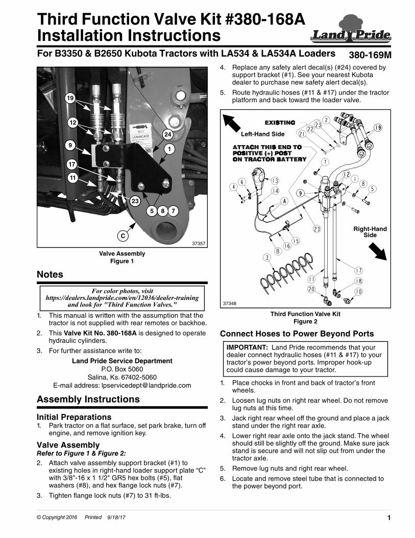
Valve AssemblyFigure 1
Notes
1. This manual is written with the assumption that the tractor is not supplied with rear remotes or backhoe.
2. This Valve Kit No. 380-168A is designed to operate hydraulic cylinders.
3. For further assistance write to:
Land Pride Service DepartmentP.O. Box 5060
Salina, Ks. 67402-5060E-mail address: [email protected]
Assembly Instructions
Initial Preparations1. Park tractor on a flat surface, set park brake, turn off
engine, and remove ignition key.
Valve AssemblyRefer to Figure 1 & Figure 2:2. Attach valve assembly support bracket (#1) to
existing holes in right-hand loader support plate “C” with 3/8"-16 x 1 1/2" GR5 hex bolts (#5), flat washers (#8), and hex flange lock nuts (#7).
3. Tighten flange lock nuts (#7) to 31 ft-lbs.
37357
12
24
17
C
75 8
11
1
19
23
9
For color photos, visit https://dealers.landpride.com/en/12036/dealer-training
and look for "Third Function Valves."
© Copyright 2016 Printed 9/18/17
4. Replace any safety alert decal(s) (#24) covered by support bracket (#1). See your nearest Kubota dealer to purchase new safety alert decal(s).
5. Route hydraulic hoses (#11 & #17) under the tractor platform and back toward the loader valve.
Third Function Valve KitFigure 2
Connect Hoses to Power Beyond Ports
1. Place chocks in front and back of tractor’s front wheels.
2. Loosen lug nuts on right rear wheel. Do not remove lug nuts at this time.
3. Jack right rear wheel off the ground and place a jack stand under the right rear axle.
4. Lower right rear axle onto the jack stand. The wheel should still be slightly off the ground. Make sure jack stand is secure and will not slip out from under the tractor axle.
5. Remove lug nuts and right rear wheel.
6. Locate and remove steel tube that is connected to the power beyond port.
37348
Left-Hand Side
Right-Hand Side
IMPORTANT: Land Pride recommends that your dealer connect hydraulic hoses (#11 & #17) to your tractor’s power beyond ports. Improper hook-up could cause damage to your tractor.
1

Assembly Instructions
Refer to Figure 4:7. Install the larger hydraulic adapter (#10) into the
power beyond port on the loader valve and 9/16" MJIC x 9-16" FJIC elbow (#18) to adapter (#10).
8. Connect 48" long hydraulic hose (#17) from port “P” to elbow (#18)
Tank Port (B3350 tractor Shown)Figure 3
Refer to Figure 3:9. Remove back right seat support stud (#25).
10. Install 3/8" MBSPP x 9/16" MJIC elbow (#20) to remaining port (#26) on the tractor where the steel tube connecting power beyond ports was.
11. Position elbow (#20) as shown and tighten.
12. Reattach seat support stud (#25) to mount (#27) and tighten.
13. Connect 62" long hydraulic hose (#11) from port “T” to elbow (#20).
14. Secure hoses (#11 & #17) to underside of tractor with cable ties (#3)
15. Replace right rear wheel and screw lug nuts on until snug.
16. Jack axle up and remove jack stand.
17. Lower tractor down and tighten lug nuts in a crisscross pattern. Refer to tractor Operator’s Manual for proper torque value.
18. Remove chocks.
19. Check tractor hydraulic fluid level. If low, add recommended hydraulic fluid. Refer to your tractor Operator’s Manual for recommended hydraulic fluid and procedure for checking hydraulic fluid level.
25
26
20
39150
27
2 Third Function Valve Kit #380-168A Installation Instructions 380-169
Third Function Valve KitFigure 4
Control Lever AssemblyRefer to Figure 4 above & Figure 5 on page 3: 1. Remove existing knob (not shown) from end of
control lever “D”.
2. Install new joystick (#13) over end of control lever “D” with push buttons facing operator.
3. Tighten set screws (#4) against control lever “D”. Tighten jam nuts (#6) to secure set screws (#4).
4. Thread wiring harness (#14) through rubber cover “E” in Figure 5 and to wiring harness (#23) shown in Figure 2 on page 1.
5. Reference Connections “A”: Connect one black wire in harness (#14) to one black wire in harness (#23) and the other black wire in harness (#14) to one white wire in harness (#23).
6. Reference Connection “B”: Connect the two red wires in harness (#14) leading from joystick (#13) to one end of wire (#16) with fuse holder (#15),
7. Connect opposite end of wire (#16) to the positive (+) post on the tractor battery.
8. Secure wiring (#14, #16, #23) with cable ties (#3) as needed.
37348
Left-Hand Side
Right-Hand Side
M 9/22/16

Assembly Instructions
Control Lever AssemblyFigure 5
Cross Beam Mount AssemblyRefer to Figure 4 on page 2 & Figure 6:1. Remove existing hardware (#21, #22, & #23) from
the right-hand side of loader cross tube “F”.
2. Orient as shown and attach bulk head mount (#2) to the right-hand side of loader cross tube “F” with removed hardware (#21, #22, & #23).
3. Tighten replaced hardware (#21, #22, & #23) to the proper torque.
Hydraulic Hose RoutingRefer to Figure 4 on page 2, Figure 6, and Figure 7:1. Route hydraulic hoses (#19) along loader arm “G”
and through loader loop bracket “H” to the third function valve assembly (#9).
2. Connect hoses to quick couplers (#12) on “A” & “B” ports of third function valve block (#9).
3. Secure hydraulic hoses (#19) as needed with cable ties (#3).
37358
Push Buttons
146
13
D
E
4
9/22/16 Third F
Cross Beam Mount AssemblyFigure 6
Hydraulic Hose RoutingFigure 7
37359
2
F
21
22
23
19
37121
19
H
G
3unction Valve Kit #380-168A Installation Instructions 380-169M

Corporate Office: P.O. Box 5060Salina, Kansas 67402-5060 USA
www.landpride.com