this article written by afcona technical team. all ...this article written by afcona technical team....
TRANSCRIPT

This article written by AFCONA technical team. All copyrights reserved and belong to AFCONA Additives @ 2005
1 This article written by AFCONA technical team. All copyrights reserved and belong to AFCONA Additives @ 2005
1. Introduction
Most coating systems need good leveling and flow in order to have a nice appearance. A flat smooth surface will also give better glossy appearance and is very eye catching. Controlling the leveling and flow of a coating is all about controlling the surface tension of the system. However some incompatible ingredients in the formulation will also affect the flow and leveling of the coating.
Before we discuss further about slip and leveling agents, it is important that we discuss and understand in detail on surface tension. Surface tension involve in almost every way in paint technology, in dispersing, leveling, adhesion, atomization in spraying and etc. 2. Surface Tension To formulate a defect free coating is all about controlling the surface chemistry of the coating. So, before we go deeper into the discussion, it is better we understand the word ‘surface tension’ in detail. The word, surface tension, will be appearing almost frequently in the discussion. The term surface is commonly reserved for the boundary between a condensed phase (liquid or solid) and a gas or liquid with the term ‘interface’ being used to describe the junction of the two condensed phase. The cohesive forces between molecules on the surface are responsible for the phenomenon known as surface tension. The molecules at the surface do not behave like other molecules on all sides of them and consequently they cohere much stronger to those directly associated with them on the surface. As shown in diagram 1, the molecules in the inner layer are in the balance or in a state of equilibrium forces between them and this will give zero force difference in all angles. The molecules on the surface are faced with an unbalance force due to missing molecules on the top surface. A net of unbalance forces are created on the surface that results in surface tension.
Diagram 1: The cohesive forces between the molecules at the surface are not evenly distributed on all sides as compared to the molecules in the inner layer, surface tension is the result of this unbalance forces. Surface tension, with symbol γ, is commonly defined as a force which acts in a material to adapt the smallest possible surface under the set conditions. This force is oriented parallel to the surface. Surface tension is the energy needed to increase the surface by a defined value. The minimum surface tension corresponds to the minimum energy. However surface tension of a specific material varies with temperature. It drops when temperature increase.

This article written by AFCONA technical team. All copyrights reserved and belong to AFCONA Additives @ 2005
2 This article written by AFCONA technical team. All copyrights reserved and belong to AFCONA Additives @ 2005
Surface tension is typically measured in dyn/cm or mN/m or mJ/m², eg, the force in dynes required to break a film of length 1 cm, equally, it can be stated as surface energy in ergs per square centimeter. Why some materials have high surface tension and some have very low surface tension? The forces interacting with each molecule determine the final surface tension of a system. The stronger these forces, the higher the value of the surface tension. Thus, these inter molecular forces play a very important role in the value of the surface tension in a specific material. The inter molecular forces are generally divided to 2 main segments: 1) Dispersive Forces,
D London Dispersive Forces
2) Polar Forces,
P Dipoles forces Hydrogen bonding Ionic bonds
This showed that substances that have different surface tension, γ, are due to different contributions of D and P forces.
Diagram 2: Total surface tension with relation to dispersive surface tension and polar
surface tension. 2.1 Inter Molecules Forces 2.1.1 London Dispersive Forces
London Dispersive forces are caused by movement of charges in non-polar molecules (e.g. hydrocarbons) induction of electromagnetic attractive forces in the electron clouds of covalent molecules by distortion of charged cloud. Distortion is a result from the electric field produced by charge distribution in nearby molecule.
Helium Atom 1 Helium Atom 2 δ - δ + δ - δ +
Diagram 3: Example of a Helium atom illustration of London Dispersive Forces
Size and shape of the molecules determine the magnitude of the London Dispersive Forces, the bigger the sizes, the higher the London Dispersive Forces.
γtot = γD + γP
e-
e- e-
e- Electrostatic attraction e-
e- e-
e- 2+ 2+ 2+ 2+

This article written by AFCONA technical team. All copyrights reserved and belong to AFCONA Additives @ 2005
3 This article written by AFCONA technical team. All copyrights reserved and belong to AFCONA Additives @ 2005
Let look at the influent of size to London Dispersive Forces. For examples, CH4, Methane is in gas form in room temperature but CH3-(CH2)4-CH3, Hexane, is liquid in room temperature and CH3-(CH2)8-CH3,octadecane, is in solid form in room temperature.
As for the influence of shape, it will also influence the value of the London Dispersive
Forces value. Please see diagram 4 for detail.
Liner Compact
Larger contact surface Spherical Higher dispersive force Lower dispersive forces
2.1.2 Dipole forces/moment Polar covalent molecules are sometimes described as "dipoles", meaning that the molecule has two "poles". One end (pole) of the molecule has a partial positive charge while the other end has a partial negative charge. Dipole forces are caused by differences in electro negativity of an atom where it has the ability to attract electrons. This action result in unequal sharing of electrons with creation of polar covalent bonding but the net charge remains the same. This effect is best to illustrated in diagram 5.
Diagram 5 : The creation of Dipole-dipole charges Even though the total charge on a molecule is zero, the nature of chemical bonds is such that the positive and negative charges do not completely overlap in most molecules. Such molecules are said to be polar because they possess a permanent dipole moment. A good example is the dipole moment of the water molecule, please see diagram 6. Molecules with mirror symmetry like oxygen, nitrogen, carbon dioxide, and carbon tetrachloride have no permanent dipole moments. Even if there is no permanent dipole moment, it is possible to
HH -- HH
2.1 2.1
non-polar
HH -- CCll
δδ++ δδ--
2.1 3.0
Diagram 4: Influence of shape on molecules London Dispersive
Forces.

This article written by AFCONA technical team. All copyrights reserved and belong to AFCONA Additives @ 2005
4 This article written by AFCONA technical team. All copyrights reserved and belong to AFCONA Additives @ 2005
induce a dipole moment by the application of an external electric field. This is called polarization and the magnitude of the dipole moment induced is a measure of the polarity of the molecular species. However we will not discuss this in detail as it not very relevant to application in paint.
The dipole moment, µ, is defined as the product of the total amount of positive or negative charge and the distance between their centroids. The centroids of the positive and negative charges in a molecule are determined in a manner similar to that used to determine the centre of mass of a system.
Dipole moment also can be calculated using the formulation shown below, however in general the calculated value is usually smaller than the measured value.
µ = eR, where
e= The charge on the electron is 4.80 X 10⁻¹⁰
R= The diameter of the two atom that created the dipole moment
As shown in diagram 5, Hydrogen gas is a non polar material, however Hydrochloric
Acid with a bonding of Hydrogen and Chlorine have different electro negative attraction ability where Chlorine have the ability of attracting electron towards them creating partially charge pole. The bonding H-Cl is actually a covalent bonding but due to the electron attraction ability, it also contain partially ionic bonding. The polar covalent bond that have the ability to perform the dipole forces are O-H, N-H, C-Cl, C-F, C-O, C-N and etc. The non or low polar bonding will not have the ability to create this action and they are C-C, H-H, N-N, O-O and etc.
The overall dipole value depends on the molecule geometry. As mentioned earlier, symmetry molecule will have no dipole moment. However, non symmetry molecules have dipole moment. Please refer to diagram 7.
Diagram 6: Influence of molecule geometry on dipole molecule
Diagram 7: Examples of the electric dipole moment
molecule µ molecule µ
Alkanes 0 NH3 1.47
C6H6 0 CH3OH 1.69
OO==CC==OO
µ = 0 D (debye)
OO
HH HH µ = 1.84 D (debye)
Debye: unit of electric dipole moment, ca. 3.336 x 10⁻³⁰ cm

This article written by AFCONA technical team. All copyrights reserved and belong to AFCONA Additives @ 2005
5 This article written by AFCONA technical team. All copyrights reserved and belong to AFCONA Additives @ 2005
CCl4 0 CH3COOH 1.70
CO2 0 H2O 1.85
CHCl3 1.06 C2H4O Ethylene Oxide 1.90
HCl 1.08 CH3COCH3 Aceton 2.85
Molecules that have dipole moment will orient themselves to create a dipole-dipole
interaction where it contributes to the attraction between molecules to molecules. This interaction is a very important interaction when we talk about High Molecular Dispersing Agent in High Molecular Weight Dispersant.
In conclusion, Dipole Moment of a molecule depends on the polarity of the structure as well as the geometry of the molecule. Note:
By reading both phenomena on dispersive forces and dipole forces, it is easy to get confused because both explanations seem similar. However, they are differences; London Dispersive Forces describes the phenomena that happened between different molecules/atom. However Dipole Moment describes the phenomena that happen within the molecule and later influencing other molecules. 2.1.3 Hydrogen Bonding
Hydrogen bond has a very strong dipole-dipole interaction (3-10 kcal/mol), typically happen in O-H and N-H bonds (H-donor). H-atom has strong affinity for non-bonding electrons (lone-pair electron) of other O- and N-atoms (H-acceptor). These phenomena will not be observed in C-H bonds.
The hydrogen bond has only 5% or so of the strength of a covalent bond, however,
when many hydrogen bonds form between two molecules (or parts of the same molecule), it can be sufficiently strong as it can be quite stable.
CC ==OO
δδ++ δδ--
CC ==OO
δδ++ δδ--
CC ==OO
δδ++ δδ--
Diagram 8: Creation of Dipole-dipole interaction among molecules that have dipole moment.

This article written by AFCONA technical team. All copyrights reserved and belong to AFCONA Additives @ 2005
6 This article written by AFCONA technical team. All copyrights reserved and belong to AFCONA Additives @ 2005
Diagram 9 : Examples for Hydrogen bonding formation in water
2.1.4 Ionic Bonding (Not covalent bonding) Ionic bonding is the result from bonding of two ions that carry opposite charges, negative (-) and positive (+). So, when 2 or more atoms/molecules meet, the forces can be attractive, + and -, or repulsion, + and + or – and -.
Ionic bonding is best described using a simple electrostatic model. The electrostatic model is an application of the charge principles that opposite charges attract and similar charges repel. An ionic compound results from the interaction of a positive and negative ion, such as sodium and chloride in common salt.
The ionic bond results as a balance between the force of attraction between opposite plus and minus charges of the ions and the force of repulsion between similar negative charges in the electron clouds. In crystalline compounds this net balance of forces is called the LATTICE ENERGY. Lattice energy is the energy released upon the formation of an ionic compound.
In coatings, the most commonly known ionic bonding materials will be inorganic pigments where a Metal element carrying a positive charge and Oxygen carrying the negative charge form a strong bond with each other. However, in organic chemistry, the elements that bind together usually involved covalent bond. Ionic bonds can also be found in common salt where neutralization takes place. Ionic bonding is the strongest among all polar forces. R-NH3+ -OOCR’ Organic Na+ -OOCR’ Mix of organic and inorganic Na+ Cl- Inorganic Comparing all forces All the forces described above can be measured or calculated and this will show that some forces are predominant and some are just a contributor. In Diagram 11, it clearly stated the strength of different forces contributing to the total of surface tension. Kcal/mol
Dispersive Forces D : London Dispersive 1
Polar Forces P : Dipole 3 Hydrogen Bonding 10 Ionic Bonding
20
(Covalent Bond) : 100
Diagram 10: Examples of salts with ionic bonding
after neutralization.

This article written by AFCONA technical team. All copyrights reserved and belong to AFCONA Additives @ 2005
7 This article written by AFCONA technical team. All copyrights reserved and belong to AFCONA Additives @ 2005
Diagram 11 : Comparison chart on different forces 2.2 Surface tension of some common materials used in coatings.
As explained, the surface tension of a material is the total energy from the Dispersive Forces and Polar Forces as shown in diagram 2. Some of the common materials involve in coating are listed below.
Table 1: Surface tension of common materials involve in coating at 20°C Diluents
Materials Surface Tension/mN/m Materials
Surface Tension/mN/m
Water 72.8 Low Aromatic White Spirit 25.0 Ethylene Glycol 48.4 MIBK 23.6 Butyl Acetate 25.3 MEK 24.6 Ethyl Acetate 24.0 Cylcohexanon 34.0 Methoxy Propyl Acetate 26.4 Iso-Propanol 23.0 Xylene 29.3 n-Butanol 24.6 Toluene 28.5 Acetone 23.5 Resins Substrate
Materials Surface Tension/mN/m Materials
Surface Tension/mN/m
Melamine Resin (HMMM) 58.0 Glass 70.0 Epoxy 47.0 Steel, Pre-treated 45.0 Polyester 41.0 PVC 39.8 Polyacrylate 35.0 Polyethylene 33.2 Long Oil Alkyd 26.0 Polypropylene 28.0 Short Oil Alkyd 29.0 PTFE 19.0
Table 2: γD and γP value Phase RT Material Chem. formula γD γP γ Water H2O 21.70 51.00 72.70 Ethanol CH3CH2OH 18.40 4.00 22.40
Polydimethylsiloxane Me-(Si(Me)2O)nSi(Me)3 16.90 2.10 19.00 Hexane C6H13 18.40 0.00 18.40 LIQUIDS Glycerol (HO-CH2)2CHOH 37.00 26.40 63.40 n-octane C8H17 21.80 0.00 21.80 Methyliodide CH3I 48.50 2.30 50.80 Fluorosilicone -(MeSiORF)n- 14.50 0.20 14.70 Ethylene glycol HO-(CH2)2-OH 28.60 29.70 48.30 Mercury Hg 200.00 284.00 484.00 Glass Si(4+) O(2-)2 29.40 43.90 73.30 Paraffin wax -(CH2-CH2)n- 25.50 0.00 25.50 SOLIDS PTFE (Teflon) -(CF2-CF2)n- 18.60 0.50 19.10 Polyethylene -(CH2-CH2)n- 33.20 0.00 33.20 Polystyrene -(CH2CHC6H5)n- 41.40 0.60 42.00 Mica Mx[AlSi3]O10(OH)2 27.30 39.80 67.10
2.3 Interfacial Surface Tension

This article written by AFCONA technical team. All copyrights reserved and belong to AFCONA Additives @ 2005
8 This article written by AFCONA technical team. All copyrights reserved and belong to AFCONA Additives @ 2005
In coating systems, we also have to deal with interfacial surface tension. The understanding of interfacial surface tension is also important in paint technology as it helps to solve many technical problems related to paint defects. In general terms, interfacial surface tension is defined as surface tension at the surface separating two non-miscible materials. In paint, the most important interfacial surface tension is listed below. In case of polymer/solvent systems typical measurements range from 0.0001 - 0.1 mN/m, for polymer/polymer-systems this interval is typically 1-20 mN/m.
Interface solid-liquid: γSL
Interface liquid-gas: γLG
Interface solid-gas: γSG In practice, to make things easier, we will assume that the interface surface tension liquid – gas is the same as the surface tension of the liquid and the interfacial surface tension of the solid and gas will be assume as the same as the surface tension of the solid. Thus what left to be study in detail will be the interface surface tension of solid – liquid. Interfacial surface tension of solid - liquid can be measured and calculated. Fowkes equation can be used to calculate the solid – liquid interfacial surface tension.
Diagram 12 : Fowkes Equation on calculating the interfacial surface tension of Solid –
Liquid. Let us calculate some examples of interfacial surface tension of water on glass as well as water on teflon surface. Table 3: Data for water, glass and teflon for calculation of the Fowkes Equation Material Chem Formulation γD γP γ Water (L) H2O 21.7 51.0 72.7 Glass (S) Si(4+) O(2-)2 29.4 43.9 73.3 PTFE (Teflon)(S) -(CF2-CF2)n- 18.6 0.5 19.1
Interfacial Surface tension of water and glass γSL = 72.7 + 73.3 - 2 [(29.4 x 21.7)½ + (43.9 x 51)½ ] γSL = 72.7 + 73.3 - 2 [25.3 + 47.3 ] γSL = 72.7 + 73.3 - 145.2 = 0.8mN/M
γSL = γS + γL - 2 ( γSD γLD + γSP γLP)
interaction of dispersive forces
interaction of polar forces
γSL = γS + γL - 2 [(γSD γLD)½ + (γSP γLP)½ ] (Fowkes equation)

This article written by AFCONA technical team. All copyrights reserved and belong to AFCONA Additives @ 2005
9 This article written by AFCONA technical team. All copyrights reserved and belong to AFCONA Additives @ 2005
With the same method, Interfacial Surface Tension of teflon and water can be calculated also and the value is 41.5mN/m 2.4 Determination of surface tension. Surface tension can be determined by several methods and the instruments are widely available in the market. In this discussion, we are going to look into the determination of surface tension of liquid as well as surface tension of solid. 2.4.1 Determination of liquid surface tension Liquid surface tension can be determined by various methods. However, in liquid surface tension, it can be divided to static surface tension and dynamic surface tension. Static surface tension is for those systems that reach equilibrium faster than measurement is completed. This is applicable to most coating process. Dynamic surface tension is for those systems that the measurement is faster than the equilibrium is reached. This is for very fast processes, like in printing, high mobility for fast created interfaces. 2.4.1.1 Method of static surface tension 1) Lecomte du Noü This method utilizes the interaction of a platinum ring with the surface that is being tested. The ring is submerged below the interface and subsequently raised upwards. As the ring moves upwards it raises a meniscus of the liquid, eventually this meniscus tears from the ring and returns to its original position.
2) Wilhelmy Plate This method utilizes the interaction of a platinum plate with the surface being tested. The calculations for this technique are based on the geometry of a fully wetted plate in contact with, but not submerged in, the liquid phase. In this method, the position of the platinum plate relative to the surface is significant. As the surface is brought into contact with the platinum plate the instrument will react to this action by the change in forces it experiences. It will register the height at which this occurs as the ‘zero depth of immersion’, just touching the liquid surface. The plate will then be wetted to a set depth to ensure that there is indeed complete wetting of the plate (zero contact angle). When the plate is later returned to the zero depth of immersion, the force it registers can be used to calculate surface tension.
F
meniscusγL
lamellar
Π=
rFL
2½γ
Diagram 13 : Demonstration of Lecomte Du Noü method

This article written by AFCONA technical team. All copyrights reserved and belong to AFCONA Additives @ 2005
10 This article written by AFCONA technical team. All copyrights reserved and belong to AFCONA Additives @ 2005
Where σ = Surface tension of the liquid L = Wetted length F = Force acting on the balance Θ = Contact angle, the plate is made of roughened platinum, see diagram 15, and is optimally wetted so that the contact angle is virtually 0°. This means that the term cosΘ has a value of approximately 1, so that only the measured force and the length of the plate need to be taken into consideration.
Diagram 15 : The reason a roughened platinum plate is used is because it has surface layer of liquid, which ensures zero contact angle.
3) Pendant Drop method The shape of a drop of liquid hanging from a syringe tip is determined from the balance of forces which include the surface tension of that liquid. The surface or interfacial tension at the liquid interface can be related to the drop shape through the following equation:
γ = ρΔ g R02 /β
Diagram 14:
Demonstration of the Wilhelmy Plate method

This article written by AFCONA technical team. All copyrights reserved and belong to AFCONA Additives @ 2005
11 This article written by AFCONA technical team. All copyrights reserved and belong to AFCONA Additives @ 2005
where γ = surface tension
ρΔ = difference in density between fluids at interface
g = gravity constant
R0 = radius of drop curvature
β = shape factor
There are many available instruments that can measure and calculate the surface tension instantly. This method has advantages in that it is able to use very small volumes of liquid, measure very low interfacial tensions and can measure more materials easily.
2.4.1.2 Method of dynamic surface tension Bubble Pressure method In a bubble pressure tensiometer, gas bubbles are produced in the sample liquid at an exact defined bubble generation rate. The gas bubbles enter the liquid through a capillary in which the radius is known. During this process, maximum pressure passes through and the value is recorded by an instrument. The following illustration shows in diagram 17, pressure curve during bubble formation plotted as a function of time:
Diagram 16: Instrument
use to perform the pendent drop method

This article written by AFCONA technical team. All copyrights reserved and belong to AFCONA Additives @ 2005
12 This article written by AFCONA technical team. All copyrights reserved and belong to AFCONA Additives @ 2005
Diagram 17 : Principles of Bubble Pressure method Picture1: The bubble is formed. Initially the pressure is below the maximum pressure; the radius of curve air bubble is larger than the radius of the capillary. Picture 2: Maximum pressure curve passes through. At this point the air bubble radius is the same as that of the capillary; the air bubble forms an exact hemisphere. The following relationship exists between the maximum pressure P max, the hydro-static pressure in the capillary P0, the inner radius r of the capillary and the surface tension: (Pmax - P0 ) . r γ = ------------------ 2 Picture 3: After the maximum pressure, the “dead time” of the measurement starts. The pressure decreases again, the radius of the air bubble becomes larger. Picture 4: The bubble finally escapes from the capillary and rises. The cycle begins again with the formation of the next bubble. Beside all the methods described above, there are still many methods available and also new developed ways to determine and measure the liquid surface tension. 3.4.2 Determine of solid surface tension Molecules in solids are immobilized, therefore measurement not possible in analogy to liquids. Measurement is indirect via the contact angle θ at the wetting edge of a defined liquid drop on the surface of the solid.
Liquid phase
θ d Diagram 18:
Measurement of θ of a known surface tension liquid to determine the
surface tension of a solid material.

This article written by AFCONA technical team. All copyrights reserved and belong to AFCONA Additives @ 2005
13 This article written by AFCONA technical team. All copyrights reserved and belong to AFCONA Additives @ 2005
The relationship between the S/L surface tensions can be derived from the equation by Young. γS = γSL + γL cosθ 3. Surface tension influent on Coating After discussing in great detail the topic of surface tension, we should now be ready to discuss the application of surface tension with effects on the coating. In this chapter we will be concentrating on discussing the surface tension influence on coating surface defects. Almost all surface defects are related to surface tension and by fine tuning or correcting the surface tension or surface tension gradient of the systems, many surface defects can be solved. In order to correct the surface tension and the surface tension gradient of the system, a surfactant need to be added as additive in small amount and these surfactants are mainly based on Modified Polydimetylsiloxane or a modified or unmodified acrylic polymer. These surfactants will reduce the surface tension of the system and the magnitude of the reduction is highly depending on the original surface tension of the surfactant and how they orientated themselves on the surface. Below are some of the surface defects that can be rectified by correcting the system surface tension or surface tension gradient.
1) Leveling & Orange peel, vertical and horizontal leveling 2) Craters or fish eyes 3) Substrate wetting 4) Edge crawling / framing effect 5) Telegraphing and Ghosting 6) Bernard Cells 7) Air draft sensitive 8) Over spay
3.1 Leveling & orange peel
We all know that besides surface tension, bad leveling or orange peel appearance can also be caused by other factors like viscosity of the paint, application method and horizontal or vertical position. All these factors can be easily rectified by paint formulator and we will not spend too much time on these factors. Here, we will concentrate more in understanding the surface tension factor or to be more precise, the surface tension gradient.
Generally, if we have leveling problem, and other factors have been rectified or
cannot be change due to the specific condition, we know that by lowering the surface tension, it will definitely improve the leveling performance of the system. However in practice, this is not always true in getting the desired result as we wanted.
Leveling also depends on time. If a coating is applied at different thickness, it will
need different time to achieve the final flat surface. Thus, the solvents that are used in the formulation are important in order to allow the time to achieve the desired paint film leveling. Below is the equation to illustrate the relation of paint film thickness with time.
Solid phase

This article written by AFCONA technical team. All copyrights reserved and belong to AFCONA Additives @ 2005
14 This article written by AFCONA technical team. All copyrights reserved and belong to AFCONA Additives @ 2005
Based on the formulation shown above, the time needed for leveling is directly
proportionate to Viscosity and inversely proportionate to surface tension and film thickness. 3.1.1 Surface tension on leveling A lower surface tension system, compare to a higher surface tension, will try to arrange itself to a bigger surface area as possible where it can have the lowest energy possible. This can be observed easily in many physical phenomena. Considering diagram 23, higher surface tension materials will try to position themselves in a more rounded shape as compared to lower surface tension materials that will position themselves in a flat shape. As we all know, flat surface will have bigger surface area that a round shapes. Considering a drop of mercury, Surface tension at 465 dynes/cm, on glass surface it will position itself into a ball shape. Then consider a drop of Xylene, surface tension at 29.3 dynes/cm, on glass surface it will position themselves in a flat shape. Another example, a lower surface tension liquid will have better atomization upon spraying. Better atomization also means that the droplets that sprayed are smaller in diameter. For this reason, it is very obvious that smaller droplets will have bigger surface area than bigger droplets. The factors contributing to a good leveling is not just simply reducing the surface tension as low as possible. If the surface tension is lower as compared to the substrate, a wavy surface is more preferred rather than a flat surface as wavy surface has higher surface area than a flat surface which is preferred by low surface tension phenomena that we explain earlier. Please refer to diagram 20.
Thus, these phenomena is very obvious in thin film coating like coil and can coating where according to diagram 19, the time for leveling will increase when the surface tension decrease and film thickness decrease. The factor of film thickness influence is more as it is in the factor of 3. However, the time allowed for leveling is very short in coil and can coating and the film thickness factor is fix and the viscosity is also almost fix. Thus the only changeable factor will be the surface tension. However high surface tension of the paint will also affect the adhesion as well as creating other defect like crater, ghosting and etc. Furthermore, coil and can coating are applied by roller and this will leave a roller mark immediately after coating. If the surface tension of the coating is too low, there is no driving force to level this roller mark and low surface tension will try to maintain the wavy surface rather than a flat surface.
Due to this fact, a true surface tension balance need to be achieved in order to have
good leveling as well as defect free coating. In this case, a fluorocarbon modified acrylic is the most suitable product as it has low surface tension to take care of the defects but not low enough to create a bad leveling.
3dGt
γη=
Leveling equation (Newtonian liquid) t Leveling time G Defect specific constant η Viscosity of liquid γ Surface tension of liquid d Film thickness
Diagram 19: Relation of surface tension, film thickness and viscosity on leveling time.

This article written by AFCONA technical team. All copyrights reserved and belong to AFCONA Additives @ 2005
15 This article written by AFCONA technical team. All copyrights reserved and belong to AFCONA Additives @ 2005
In practice, we noticed that for most types of coatings, lowering the surface tension do help in enhancing good leveling, in contradiction with the explanation above. Looking back to the equation in diagram 19, the film thickness factor is very important as they are in factor of 3. In addition for normal coating, the film thickness is much higher than coil and can coating in the factor of 2 - 5. Moreover, the time allowance for the coating to flow is also much longer; few seconds for coil and can and for normal coating can be 5 – 15 minutes depending on the formulation and application. Thus, this will allow the surface tension factor more room to influence the final appearance. The factor of surface tension is no longer significant in influencing the time needed for leveling. Lowering the surface tension of a coating microscopically will allow the liquid to have better localize mobility and substrate wetting and this is best explained in the Xylene and Mercury drop on the surface of glass. Xylene will have a flat shape and Mercury will have a round shape. Time do not influence any more in this case, because as we noticed, no matter how long they allow to stay on the glass surface, their position will remain the same. Lowering a surface tension of a coating will reduce the attraction forces locally on the surface between nearby molecules. This will eventually allow better flow. Thus in normal coating, when the thickness of paint film is thicker, the time allowed to flow is also higher, the effect of lowering the localize forces will be the only factor to obtain a good flow and good leveling appearance. That is why lowering the surface tension of a normal coating will allow better leveling. However we will also explain that lowering down surface tension is a general term but the most important factor to ensure good leveling will be the surface tension gradient that will be explain in 3.1.2. In conclusion, leveling is a complex subject if we analyze it microscopically and it all about obtaining the optimum balance of each factors; surface tension, condition of application, viscosity and etc to ensure a good leveling and defects free coating.
Flat surface with lower surface area
Wavy surface with higher surface area
Surface tension, mN/m
Film Thickness and time allow to leveling 0
Diagram 20: Flat and wavy surface
Diagram 21: Relation of surface tension of the paint and film thickness and time allowed to achieve good leveling
Area when film thickness is low and time for leveling is limited where the surface tension
will be the only factor for good leveling
Area when film thickness is higher and time for leveling is also longer where the factor
of local molecules forces is important

This article written by AFCONA technical team. All copyrights reserved and belong to AFCONA Additives @ 2005
16 This article written by AFCONA technical team. All copyrights reserved and belong to AFCONA Additives @ 2005
3.1.2 Surface tension gradient influence on leveling As mentioned above, lowering the surface tension will improve the leveling. However in many cases, it seems like it does not happen in this way. 2 surfactant additives that have the same low value of surface tension have different performance in leveling. This is because of the real factor for good leveling is not only lowering the surface tension but is the low surface tension gradient. On the surface of a wet paint, if we observe microscopically, every spot on the surface will not have the same surface tension. Thus the different of one specific spot of surface tension and the nearby spot is the surface tension gradient. A low surface tension will have lower possibility to have very high surface tension gradient due to the fact that lower surface tension has less room for variation. However high surface tension will allow more possibility of higher surface tension gradient as it has more room of variation.
A surfactant that is added into the system will have different orientation on the surface due to its molecular structure, compatibility with the system, polarity, steric hindrance and critical micelle concentration. These orientations shall directly influence the surface tension gradient as explained above
. If γ1 and γ3 is high surface tension area and γ2 and γ4 represent a low surface tension area, and if the difference is significant, leveling of the final coating also can be orange peel. Surface tension is a state of energy where if there is a difference, it will flow from low surface tension area to high surface tension area. This explained the orange peel effect as shown in the diagram. 3.2 Crater and fish eyes Craters and fish eyes are formed due to the contamination of low surface tension materials that are not compatible with the system. The contaminated low surface tension material can be coming from one or more of the ingredient in the formulation like defoamers or material that drops into the paint during production, dilution or application and it can also be the contamination on the substrate. A low surface tension material will de-wet from the system and creating a crater or a fish eye. For more information on the theory of wetting and de-wetting can be found in substrate wetting section. Generally, craters are those craters like or shallow hole like formation on the surface and the depth of the crater doesn’t reach the substrate. However, fish eyes are those craters or deep hole and the depth reaching the substrate. Craters are cause by extenders and internal contamination and fish eyes are normally cause by substrate contamination and serious internal incompatibility and low surface tension contamination. In order to rectify this problem, a lower surface tension material is to be added in order to lower the surface tension of the system to the level that the system surface tension is lower than the surface tension of the contaminated material. Upon reaching that, the crater or fish eye can be overcome as the system can wet the contamination. 3.3 Substrate wetting
γ1 γ2 γ3 γ4
Diagram 22: Surface tension gradient influence in leveling
γ1/ γ2 >>1 γ3/ γ4 >>1

This article written by AFCONA technical team. All copyrights reserved and belong to AFCONA Additives @ 2005
17 This article written by AFCONA technical team. All copyrights reserved and belong to AFCONA Additives @ 2005
Wetting property of paint to substrate is solely depending on the surface tension difference between the paint and the substrate. In general term, the surface tension of the paint should be lower than the substrate in order to have good wetting as well as good adhesion of paint on that particular substrate. Wetting property can be determined by the contact angle of a liquid on the solid surface and it can be calculated using Young equation.
Spreading will be the most favored option that we need to achieve in coating in order to ensure good substrate wetting. Thus as showed in the spreading coefficient, the surface tension of the solid, γS the substrate, have to be higher than the surface tension of the liquid, γL the paint.
Θ
90 ° < Θ < 180 °
Negligible wetting No wetting
Θ 0 ° < Θ < 90 ° Partial wetting Complete wetting
Θ = 0 °
spreading
Θ = 0 °
Young equation: γS = γSL + γL cos Θ γS = γSL + γL
cos Θ = 1
(γS - γL) - γSL > 0 = SIn order to ensure spreading : γS > γSL + γL
S = Spreading coefficient
Positive spreading coefficient = spreading is energetically favored
Diagram 23: Wetting principles based on Young Equation

This article written by AFCONA technical team. All copyrights reserved and belong to AFCONA Additives @ 2005
18 This article written by AFCONA technical team. All copyrights reserved and belong to AFCONA Additives @ 2005
Addition of a lower surface tension surfactant will reduce the surface tension in the system and this will further improve the system substrate wetting property. In most case, a sufficient low surface tension non silicone surfactant will perform better in substrate wetting as compared to the non silicone surfactant which are normally higher in M.W and because of this, they are active in the interface of substrate and liquid rather than silicone type that always active on the gas and liquid interface. 3.3 Edge crawling / framing effect Framing effect or edge crawling is a defect that easily can be identified on a panel. A thicker dry film will appear at all corners of a panel. This defect is sometime also called as fat edge. The diagram above shows how framing defect is created. As it involved solvent evaporation at the edge, this defect happens very obviously in solvent rich or low application viscosity system. For solvent free system, this defect is not so obvious. However sometime it also can be found in solvent free system, due to the high activity of cross linking of the system. The high edge surface area proportionally increases the cross linking rate of the polymer in the paint. Thus, the surface tension at the edge will also increase and lead to the same phenomena.
Wet paint Solvent evaporation
Substrate
After paint applied, solvents will start to evaporate and the
surface tension of the paint is gradually
increases.
The surface area at the edge is higher due to the curve shape. Bigger surface area will
lead to faster solvents escaping and the rate of surface tension increase is also higher.
This created a surface tension gradient where the edge has higher surface tension comparing to those inner areas that have
lower surface tension.
γ, Higher Area
γ, Lower Area
The surface tension gradient created will result a pulling forces at the edge where the liquid inside will be pull to the edge.
Framing defect created.
Diagram 24 : Explanation on how Edge crawling or Framing effect happens

This article written by AFCONA technical team. All copyrights reserved and belong to AFCONA Additives @ 2005
19 This article written by AFCONA technical team. All copyrights reserved and belong to AFCONA Additives @ 2005
In most cases, incorporation of a low surface tension surfactant will solve the problem. Among all surfactants, the Fluorocarbon Modified Acrylic Polymers are the most suitable surfactant to solve this problem. 3.4Telegraphing and Ghosting Telegraphing and ghosting can be referred to as a defect which happens after paint is cured; the profile of the substrate is appearing and visible on the newly coated dry paint film. However this is mainly because primer or primer surfacer has not been used prior to application of topcoat. This is not related to surface tension but lower surface tension paint will result in more obvious to this defect. Using an appropriate primer or surfacer will solve this profiling problem. Ghosting sometime also referring to the ghosting profile created due to lack of replenishment of paint on certain area resulting in different thickness of the coating. Typically, this happens in paint applied by brush and roller. Most of the time, this is because of the rheology of the paint where viscosity is too high, however addition of some low surface tension surfactant will definitely help to improve this defect. The theory behind it is almost the same as substrate wetting and leveling as discussed earlier. The 3rd phenomena that Ghosting is referred to substrate contamination that have a profile, like the substrate been touch and leave finger print, oil stain, wiping traces and etc. The profile of this contamination will appear after the paint dries. In some cases, migration of chemicals like plasticizer, silicone leveling agent and etc, also happen and the migration material gives a profile on the dry paint. All this can be solved by incorporating a low surface tension surfactant. For non migration contamination, a fluorocarbon modified acrylic polymer will be most suitable to solve the problem and for those migrations contamination, silicone type will be more effect. 3.5 Bernard Cells Bernard cell is a defect of color separation due to different in surface tension gradient during solvent evaporation and curing. In most polar and/or high surface tension system and/or high evaporation rate solvent systems, Bernard cells are the common defect. The surface of these systems has high surface tension gradient and when solvents evaporating from the system, a local circulation are created as shown in the diagram above. This circulation also carry along pigments and resins where the surface tension gradient energy on the surface act as a separator for pigments or fillers and due to all of them have different particles size and different density, the mixture of pigments and/or filler will be separate out according to their particles size and density.
However Bernard Cells are a very easy solve defect. A small amount of compatible silicone surfactant in most cases will definitely solve the problem. Please look diagram 25 below showing the picture of a real Bernard cells on a panel. When the panel was place and dry at horizontal level, Bernard Cells appearance will be a
High surface tension
Low surface tension
Diagram 24 : Surface tension gradient and localize circulation created color separation of color on the surface

This article written by AFCONA technical team. All copyrights reserved and belong to AFCONA Additives @ 2005
20 This article written by AFCONA technical team. All copyrights reserved and belong to AFCONA Additives @ 2005
. . . . .
. . .
. . .
. . .
close pack hexagon shape where each hexagon shape representing a circulation as explained above. However if the panel was placed and dried at vertical level, silking effect will happen and the effect shown in the diagram below.
3.6 Air draft sensitivity This defect occurs during forced drying when coatings are applied to a large and/or warm substrate. There is a loss of wetting in local regions of higher surface tension cause by irregular solvent evaporation rates due to air flow (ventilation). Coatings that are faced with this problem will crawl and shrink at the local region that have low surface tension to the region that have high surface tension. This defect again can be solved by addition of surfactants that have low surface tension. 3.7 Over spray Some object have more than 1 color and those colors are spray continuously one to the other without waiting for the 1st coat to reach enough surface cure to mask the area. Thus when spraying the 2nd coat, it will “fly over” to the uncured 1st coat. If the color of the 2nd coat is unable to be wetted and covered by the 1st coat, then we have an over spray problem. Typical of such object is industrial drum. In order to rectify the problem, add a low surface tension surfactant into the 1st coat paint in order to bring down the surface tension of the 1st coat lower than the 2nd coat. With the low surface tension, the 1st coat will wet the 2nd coat over spray paint and bring down to the bottom so that they are not visible.
Horizontal Bénard cells
Vertical Silking
Diagram 25 : Real panels on Bernard Cell and silking appearance
1st Coat
2nd Coat
Diagram 26 : Over spray problem
Lower surface tension, 1st
Higher surface tension, 2st

This article written by AFCONA technical team. All copyrights reserved and belong to AFCONA Additives @ 2005
21 This article written by AFCONA technical team. All copyrights reserved and belong to AFCONA Additives @ 2005
4.0 Polymers that act as low surface tension surfactant in coating – slip and leveling agent
Most of the time when we talk about slip and leveling agent in coating industry, the first material that come to our mind will be always Polydimetylsiloxane (also refers as Polysiloxane). However, here we will also look into the non-silicone type of leveling agents which their basic chemistry are based on Acrylic polymer with or without special modification.
In coating industry, Polysiloxane has helped thousand of paint formulators solving their daily surface problem (as mentioned in section 3.) but unfortunately they do carry some side effect such as intercoat adhesion, telegraphic and etc. That is why some of the formulators are skeptical to use silicone-containing materials due to the unwanted effect. Although Acrylic Polymers are widely used in the market as the substitute of Polysiloxane but the effectiveness to eliminate surface defect still not as efficient as compared to Polysiloxane. However, they do not carry the side effects that silicone materials have. Thus, in order to make acrylic polymer materials have closer properties to silicone material, AFCONA modified them with other low surface tension group such as Fluorocarbon. 4.1 Polysiloxane The first synthesis of Polysiloxane was made as early as 1872; it was not until the late 1930s that the practical functions of these polymers were appreciated. Methyl Silicone was so different in composition, in structure, and in physical and chemical properties that it was beyond the everyday thinking of chemist and engineers fifty years ago. Organometallic chemistry had scarcely entered into their training, and, anyway, silicone was not considered a metal – it was a singularly un-reactive metalloid not yet even recognized as a semiconductor. However, the first Methyl Silicone resins and oil were so different from those of the established materials that the silicone polymers were bound to find a place just because they could do some things that the ordinary polymers could not do.
Due to their special arrangement of bonding angle that resulted the individual atom can arrange themselves with lowest energy than other normal organic materials (Except Fluoro Carbon), thus they have an extremely low surface tension behavior than most of the organic material. Some of the reasons for this particular polymer to have low surface tension are briefly explain as below:
a) The length of the Si-O and Si-C bonding are long as compared to C-C, thus it reduces the steric hindrance effect on Methyl and Silicone.
b) The property of the Si-O bonding is half ionic (41%), due to this fact, the Si-O-Si bonding can be bended at the oxygen atom at the degree of 120 - 145°. Thus it further reduces the steric hindrance effect on Methyl and Silicone.
4.1.1 Type of Polysiloxane 4.1.1.1 Pure Polydimetylsiloxane
Si
O
Si
O
Me Me Me Me
Diagram 28: Polydimethylsiloxane molecular structure
120 - 145°
Diagram 27 : Over spray problem rectification

This article written by AFCONA technical team. All copyrights reserved and belong to AFCONA Additives @ 2005
22 This article written by AFCONA technical team. All copyrights reserved and belong to AFCONA Additives @ 2005
The basic structure of a Polydimetylsiloxane is shown below; this is not a modified material where it has the original properties of a silicone such as giving high slip, defoaming, form stabilizing, leveling and etc. The chain length, n, will determine it final properties. Due to it original structure, most of the time they have very bad compatibility with most resin use in coating. However they do give very good slip but they will contaminate the subsequence coat as well as the production floor where crater will happen to other coatings. Below are the general properties of an unmodified Polydimethylsiloxane. Property General Performance Slip 8 - 10 Leveling 6 - 8 Defoaming 6 - 9 Foam Stabilization 1 - 3 Anti-crater 1 - 3 Contaminating 8 - 10 Scale of 1-10 1=worst 10=excellent Nowadays, this type of silicone is no more or it find very little usage in coating industry mainly due to it contaminating effect. 4.1.1.2 Branch / comb modification Polysiloxane The comb structure will be the most common modification of Polysiloxane. Various modifications can be done at the side group according to the required performance. In general, polyether is the most common grade where they are use widely as slip and leveling agent in all types of coating. Alkyl also can be incorporated in order to reduce the polarity of the polymer. In order to increase the surface tension reduction property, fluorocarbon group also can be incorporated to enhance the anti-crater as well as substrate wetting performance. The diagram below shows general structure of a comb type of Polysiloxane. In AFCONA, we produce polyether modification, fluorocarbon modification as well as alkyl modification type of Polysiloxane. The diagrams below show the general molecular structure several types of comb modification Polysiloxane.
Me Si O Si O Si Me
Me
Me
Me
Me
Me
Men
CH3 Si O Si
CH3
CH2
CH3
CH3
Si CH3
CH3
CH3
O Si O
CH3
CH3 mCH2
CH2
O
CH2
CH2
O
HC
CH2
CH3
O
R n
x
y
Modification group
Diagram 29: Un-modified
Polydimethylsiloxane molecular structure
Diagram 30: Branch or comb type of
Polysiloxane

This article written by AFCONA technical team. All copyrights reserved and belong to AFCONA Additives @ 2005
23 This article written by AFCONA technical team. All copyrights reserved and belong to AFCONA Additives @ 2005
As the comb structure have many possibility of modification, the table below shows the general properties with regards to the modification and ratio of each segment. Table 4: Properties of the silicone according to the parameter Property General Performance
X + Y = Longer X > Y Y > X m > n
FC Modification
Slip 4 – 6 6 – 8 6 - 9 7 – 10 5 – 8 Defoaming 1 – 3 1 – 2 2 – 3 6 – 8 1 – 3 Foaming 6 – 9 6 – 8 5 – 7 2 – 5 6 – 8 Leveling 6 – 7 7 – 9 7 – 9 6 – 8 7 – 10 Contaminating 1 1 – 3 1 – 3 5 – 7 2 – 5 Anti-crater 5 – 8 6 – 8 6 – 8 3 – 5 7 – 10 Possible water soluble 6 – 9 8 – 10 3 – 5 2 – 5 6 – 8 Substrate Wetting 5 – 7 5 – 7 5 – 7 3 – 5 7 – 9
Scale of 1-10 1=Worst 10 = excellent Table 5: Properties of the silicone according to the parameter Property General Performance
CH3 Si O Si
CH3
CH2
CH3
CH3
Si CH3
CH3
CH3
O Si O
CH3
CH3 mCH2
CH2
O
CH2
CH2
O
HC
CH2
CH3
O
R n
x
y
Important parameter for different performance:
• ratio n : m • total length n + m • spacer between Si and polyether • ratio x : y • sequence x and y (blocks xy, yx,
random) • total length x + y • end group R reactive (acrylate,
amino, carboxylic acid, NCO, fluorocarbon)
EO
PO
CH3 Si O Si
CH3
CH2
CH3
CH3
Si CH3
CH3
CH3
O Si O
CH3
CH3 mCH2
CH2
O
CH2
CH2
O
HC
CH2
CH3
O
R n
x
y
Alkyl w
ith C5 – C
18 Important parameter for different performance:
• ratio n : m • total length n + m • total length of alkyl
Diagram 31: Branch or comb type of Polyether
modified Polysiloxane
Diagram 32: Branch or comb type of Polyalkyl
modified Polysiloxane

This article written by AFCONA technical team. All copyrights reserved and belong to AFCONA Additives @ 2005
24 This article written by AFCONA technical team. All copyrights reserved and belong to AFCONA Additives @ 2005
Alkyl
ModificationLonger Alkyl
Shorter Alkyl
Slip 4 – 7 2 – 4 6 - 9 Defoaming (In low polar system) 2 – 10 2 – 5 7 – 10 Defoaming (In high polar system) 2 – 10 7 – 10 2 – 5 Leveling 6 – 9 7 – 9 7 – 9 Contaminating 1 1 1 Anti-crater 4 – 6 6 – 8 6 – 8 Possible water soluble 1 1 1 Substrate Wetting 6 – 8 6 – 8 6 – 8
Scale of 1-10 1=Worst 10 = excellent 4.1.1.3 End modification Polysiloxane The reason for end modification is to maintain as much as possible the methyl group in the polymer in order to obtain better slip. The methyl group will be the group for responsible for the slip performance. Below show a general structure of an end on modification of a Polysiloxane. In most cases the end of modification group are polyether. The performance of the Polysiloxane is highly depending on the modification. As shown below, the polyether modification and the ratio between x:y will modified the same properties as show in the comb structure. However in this case, as most of the methyl groups were preserved and inert, thus it normally gives much better in term of slip performance than polyether modification comb structure. 4.1.2 The slip performance of silicone Most resins in coating industry do not contribute to a slippery surface after they cured or dried. In order to increase the slip performances for better mar resistance and scratch resistance, most formulator need to add in some additives. The range of slip additives available are Polysiloxane and waxes. In this topic we will have in depth discussion on Polysiloxane.
Si O Si O Si
Me
Me
Me
Me
Me
Men
Si
CH3
CH3
Si
CH3
CH3
O Si O
CH3
CH3n
xy
CH2CH2CH2OCH2CH2OHCCH2
CH3
OR CH2CH2CH2 EOx POy O R
Diagram 33: End modification of Polysiloxane
Diagram 34: End on modification of Polysiloxane

This article written by AFCONA technical team. All copyrights reserved and belong to AFCONA Additives @ 2005
25 This article written by AFCONA technical team. All copyrights reserved and belong to AFCONA Additives @ 2005
Whenever a slip agent is added, they are all temporary unless they have reactive group that react with the binder system. They can be easily washed away by detergent as well as from touching with finger. Polysiloxane is a surfactant that easily migrates to the surface that gets contact with them. This is also why a slip performance of a silicone reduces over time.
Diagram 35 showed how a silicone oriented itself on the surface of the coating. The methyl group will be the group that will determine the slip property of the silicone. The ideal hypothetical theory is that the Methyl groups stretching out to the air, forms a monolayer, and gives the slip property. This means the slip property of a Polysiloxane is not only depends on the amount of Methyl group in the polymer, but it also depends on the ability of the polymers to allow them to orientate on the surface in such a way in order for the methyl group stretch out to the air. 4.1.2.1 Types of slip The performance of slip generally can be divided to 2 types, dry and oily type. The dry type gives a very soft feeling to hand and has less tendency to leave any visible finger print on the panel, if use in the range of common dosage. This is very good for wood coating, general electrical appliances and plastic coating. The final products for these coatings are meant to be touch regularly. Thus nobody will like a coating that can easily leave a finger mark as it make them look dirty. The oily type generally gives much higher in slip at lower dosage, but they are easily leaving a finger mark after been touched. The advantages of the oily type are that they enhance dry film build and promote wet look property of a dry paint. This is highly needed in Automotive Industry where a wet look coating will enhance the beauty of the car. It is very common that in coating industry, slip performance is judge by manually by using the feeling of touch. So, this is a very subjective matter. There are also some other methods that available for us to measure or determine the slip performance by measuring the friction index of the coating with a content weight. Below is the diagram to show a simple way to measure the fiction index.
Diagram 35 : Orientation of PDMS at coating surface
Types of slip
Dry type
Oily type
- Very soft hand feeling - No finger print stain - Suitable for wood coating,
plastic paint, general appliances
- Oily hand feeling - Easy finger print stain - Promote dry film build and
wet look appearance - Suitable for automotive paint
OSi
O O O O
H3C CH3
Si
H3C CH3
Si
H3C CH3
Si
H3C CH3
Diagram 36 : Type of silicone and their properties

This article written by AFCONA technical team. All copyrights reserved and belong to AFCONA Additives @ 2005
26 This article written by AFCONA technical team. All copyrights reserved and belong to AFCONA Additives @ 2005
4.1.2.2 Determination of slip Besides determining slip properties by hand, slip also can be determined by finding the friction index of the surface of the coating. a) Self made slip angle measurement Above is a simple set up that can be easily conducted in the lab. Place a coated panel that needs to determine the surface slip on horizontal level and place a specific weight on top of the panel. Lift the panel by finger and once the weight start to slide down the coated panel, immediately stop the lifting. The angle of the coated panel can be measured by eye with horizontal level as shown on above diagram. The angle, θ, will directly reflect the degree of slip on the coated panels, smaller angle indicates higher degree of slip. As this test method is done manually, they do have few difficulties and error. The weight that is used in the test is recommended to be cleaned with appropriate solvent (depending on the solubility of the silicone) every time we start a new test. This is because silicone can migrate and after a test, the silicone on the coated panel will transfer to the weight and this will influence the result of the subsequence test. b) Scientific Instrument for slip determination There are few friction index instruments available in the market. The basis of this instrument is using a pointed material to scratch on the coated panel. A force will be applied when we start to pull the pointed material until it reach a constant force. This constant force is recorded and will convert directly to friction index, the lower the friction index indicating higher degree of slip. 4.1.3 Dilemma of silicone Polysiloxane is a very useful material in coating industry as it can help us to solve many surface defects if use correctly. However if the dosage is high or not correct, Polysiloxanes, besides solving problem, they will also create other surface problem and in most cases are overcoat adhesion and crater due to contamination to subsequence coats or to other coating. That is why most formulators in coating industry are reluctant to use silicone material due to the problems mentioned. However if silicone is to be used wisely, with
90°
0°
Lifting force, lift until the weight object start to skid d
θ
Coated panel
Weight
F, Forces apply
Diagram 37 : Simply method to test slip performance
Diagram 38 : Method to test friction index

This article written by AFCONA technical team. All copyrights reserved and belong to AFCONA Additives @ 2005
27 This article written by AFCONA technical team. All copyrights reserved and belong to AFCONA Additives @ 2005
combination with other non silicone leveling agent, they only need a very small quantity to solve most of the surface defects. 4.2.3.1 Overcoat adhesion problem Polysiloxane is a surfactant that has high surface activity. In a non reactive silicone, the silicone always migrated to the top layer once a 2nd coat is coated on top of a 1st coat. The above diagram show how silicone migrate from1st coat to 2nd coat. The explanation of adhesion problem is explained below: Intercoat adhesion will not happen if there is no β silicone on the interface. Once the 2nd coat is applied, the β silicones will first migrate to the 2nd coat and the γ silicones will start to migrate to the interface and giving enough time, they will eventually move to the 2nd coat. If the drying time is long enough, all silicones should move to 2nd coat and that is what we preferred in order to avoid intercoat adhesion. However, if the quantity or amount of β and γ are a lot and they are unable to migrate before the paint viscosity thickens during curing to stop them from migrating further, the overcoat adhesion will be a problem. This means, in practice a high dosage of Polysiloxane will cause intercoat adhesion but if the dosage is low, normally < 0.1 solid on total formulation (varies from silicone to silicone), the problem of intercoat adhesion will not happen, but at low dosage, most of the time it is unable to give the desired performance of the 1st coat. 4.2.3.2 Contamination Most modified silicone will not have the contamination problem as they are modified and have good compatibility and rather high molecular weight. A silicone is said to be contaminating when they cause crater to the top coat or/and to other coating. As mentioned before, crater caused by surfactant that have low surface tension and not compatible with the
Substrate
1st coat
2nd coat
= Silicone that stays in the 2nd coat, for easy reference, is labeled as α
= Silicone that stays in interface of 2 coats, for easy reference, is labeled as β
= Silicone that stays in the 1st coat, for easy reference, is labeled as γ
Diagram 39 : Diagram showing the orientation of silicone after a 2nd coat

This article written by AFCONA technical team. All copyrights reserved and belong to AFCONA Additives @ 2005
28 This article written by AFCONA technical team. All copyrights reserved and belong to AFCONA Additives @ 2005
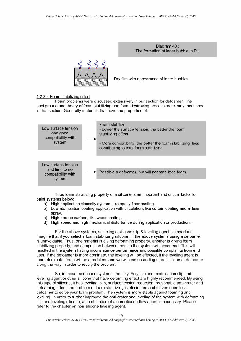
system, which means if the contaminating silicones have good compatible, than they will not cause crater. Typical contamination do happens in the non modified silicone. It happens when the coating line is on a conveyor and need low baking temperature for force dry, 60°C - 80°C, or high baking temperature for curing at 100°C - 230°C. At both range of temperature, the silicone will slowly evaporate in the oven and upon reaching certain concentration it will fall back to the panel. If this silicone is not compatible with the system during that stage, craters will form. 4.2.3.3 Inner Bubble for PU Inner bubbles are a common problem in PU coatings that have a dry film thickness of more than 30µm. A thicker dry film thickness is more sensitive to inner bubbles. Most formulator think that this is a foam problem but in actual case, it is not foam but is actually caused by localize different density of cross linked resin that give different reflective index and they are visible for our eyes to detect it. The most visible angle to detect inner bubble will be at 45° angle. If it is foam, this is mainly because of the mechanical bubble where it depends on the application method or the water level in the system is significantly high. We know that inner bubbles are caused by silicone. The conditions for a system that will increase the sensitivity to inner bubbles are shown below.
1) Thicker coat, > 30µm dry film 2) Increase in OH value of the resin 3) Lower molecular weight resin 4) Lower surface tension of Polysiloxane incorporated.
The diagram below shows how inner bubbles are created.
Polysiloxane
Wet Film
PU coatings have the tendency to retain solvents in the system. When the surface reached the semi dry state, it also means that the semi dry area is not mobile anymore. Solvent will still keep on evaporating and this will cause a localized circulation as shown above. However with the presence of the silicone, the silicone will keep on migrating to the surface and causing the upper layer to have lower surface tension than the lower part. The circulation will get more drastic due to the migration of silicone as well as the surface tension gradient between the localized upper layer and lower layer and this caused a different density of cross linking in the lower part. When everything is cured, inner bubbles will be formed and it is obvious for our eye to detect it.
Semi-dry film
This article written by AFCONA technical team. All copyrights reserved and belong to AFCONA Additives @ 2005
29 This article written by AFCONA technical team. All copyrights reserved and belong to AFCONA Additives @ 2005
4.2.3.4 Foam stabilizing effect Foam problems were discussed extensively in our section for defoamer. The background and theory of foam stabilizing and foam destroying process are clearly mentioned in that section. Generally materials that have the properties of: Thus foam stabilizing property of a silicone is an important and critical factor for paint systems below:
a) High application viscosity system, like epoxy floor coating. b) Low atomization coating application with circulation, like curtain coating and airless
spray. c) High porous surface, like wood coating. d) High speed and high mechanical disturbance during application or production.
For the above systems, selecting a silicone slip & leveling agent is important. Imagine that if you select a foam stabilizing silicone, in the above systems using a defoamer is unavoidable. Thus, one material is giving defoaming property, another is giving foam stabilizing property, and competition between them in the system will never end. This will resulted in the system having inconsistence performance and possible complaints from end user. If the defoamer is more dominate, the leveling will be affected, if the leveling agent is more dominate, foam will be a problem, and we will end up adding more silicone or defoamer along the way in order to rectify the problem. So, in those mentioned systems, the alkyl Polysiloxane modification slip and leveling agent or other silicone that have deforming effect are highly recommended. By using this type of silicone, it has leveling, slip, surface tension reduction, reasonable anti-crater and defoaming effect, the problem of foam stabilizing is eliminated and it even need less defoamer to solve your foam problem. The system is more stable against foaming and leveling. In order to further improved the anti-crater and leveling of the system with defoaming slip and leveling silicone, a combination of a non silicone flow agent is necessary. Please refer to the chapter on non silicone leveling agent.
Dry film with appearance of inner bubbles
Low surface tension and good
compatibility with system
Foam stabilizer - Lower the surface tension, the better the foam stabilizing effect. - More compatibility, the better the foam stabilizing, less contributing to total foam stabilizing
Low surface tension and limit to no
compatibility with system
Possible a defoamer, but will not stabilized foam.
Diagram 40 : The formation of inner bubble in PU

This article written by AFCONA technical team. All copyrights reserved and belong to AFCONA Additives @ 2005
30 This article written by AFCONA technical team. All copyrights reserved and belong to AFCONA Additives @ 2005
4.1.4 Additional information on Polysiloxane 4.1.4.1 Improve intercoat adhesion by using Polysiloxane We talk about intercoat adhesion that caused by silicone to coating, in actual case; using silicone wisely actually can even improve intercoat adhesion. How could this be? This can be done with a present of silicone at small amount on the 1st coat. Explanation on how silicone improved intercoat adhesion is given below. 4.2 Non silicone leveling agent – Modified Acrylic Polymer Polysiloxane is very useful in solving many problems in coating industry, however it can also cause other problems if present in, relatively, high concentration as discuss previously. Therefore it needs more care, experience, knowledge and through trial and error in order to obtain the optimum performance and balance with other ingredients in your system. Due to its unwanted side effects; in intercoat adhesion, contamination, foam stabilizing and inner bubble problems, it restricted formulators to incorporate them in just a very small amount in the formulation in order the dosage does not allow the problems to occur. At that small dosage, in most cases, it can’t perform satisfactorily or comes even close to the desired performance of the formulators. Due to this, formulator either has to find a less sensitive silicone or use in combination with other additives like waxes, non silicone additives and etc. Here, we are interested to discuss further on Acrylic based non silicone flow and leveling agent. Acrylic based flow additives agent is also widely used in the coating industry, however many formulators assumed that the acrylic based flow agent have less scope of usage than silicone. If silicone does not have the unwanted side effects, there will be no demand of acrylic based flow agent. In actual case this is not true. The present of acrylic based flow agent together with a silicone in the formulation, help the silicone to perform better in flow, leveling, surface tension reduction, anti-crater and etc except for only one property, SLIP.
2nd Coat
Once the 2nd coat was coated, due to the nature of silicone, they will migrate to the 2nd coat immediately. This action creates a lower surface tension area in the 2nd coat just on top of the 1st coat. This surface tension reduction will improve the wetting of 2nd coat on the 1st coat and eventually the 2nd coat will wet better on the 1st coat. Obviously it improved the overcoat adhesion of 2nd cost to the 1st coat.
That is also why the dosage must be low and before
the drying time is achieved, all silicones have to move to the 2nd coat. In practice, a dosage < 0.05 solid on total formulation is safe to perform this action.
1st Coat
Diagram 41 : The migration of silicone at low dosage to improve
the adhesion

This article written by AFCONA technical team. All copyrights reserved and belong to AFCONA Additives @ 2005
31 This article written by AFCONA technical team. All copyrights reserved and belong to AFCONA Additives @ 2005
Thus, the present of acrylic based flow agent is very important and it is recommended to use together with silicone based in order to create a stable, economic, problem free and excellent surface coating properties. 4.2.1 Types of Acrylic based flow agent 4.2.1.1 Straight acrylic with alkyl, polyester or polyether modification. Synthesis of acrylic polymer is based on radical polymerization. Most acrylic polymers are produces through random radical polymerization, where peroxides or azo initiators are used as initiator. There are many acrylates and vinyl monomers available in the market for synthesis of acrylic polymer. Below is a typical reaction of an acrylic polymer where variation of R2 to achieve any modification that is wanted (any other reactive functional also can be select), in a mixture of different modified monomer. Thus, there is a lot of possibility to have different modification to serve different purposes. Polyacrylates has one unique property; their flow performance is very good. Most of the time, many people referred to flow and leveling as the same, in fact the result from this action is the same but if we look into microscopically how it works, they are some differences. Polysiloxane responsible for reducing the surface tension as we referred to as leveling, however, as mentioned earlier, reducing surface tension is not a guarantee for obtaining a flat surface for the coating. Surface tension gradient is the factor. Polyacrylate is the flow additives that responsible for localized homogeneity of the surface tension as we refer to as flow. By localized homogeneity of the surface tension, it reduces the surface tension gradient to achieve a real flat surface for the coating. Polysiloxane is a very surface active polymer and is understandable that they have very low surface tension and they always try to orientate themselves as much as possible, subjected to critical micelle concentration (CMC), on the interface of air/liquid. However polyacrylate is not low in surface tension, which means they oriented and active inside the coating and little on the interface of liquid/solid. With the combination of the activity on the surface and inner paint film, a good leveling and flow can be obtain. Below are the comparison chart between Polysiloxane and polyacrylate. Please note that the comparison result is relative to both products. Table 6: Comparing performance of a Polysiloxane and polyacrylate Properties Polysiloxane Polyacrylate Slip Very high None
H2CC
CO
R1
OR2
R1 = H or CH3R2 = H or alkyl
acrylic monomer
Initiator X2
ΔT
X CH 2 C X
CO
R1
npolyacrylate
n OR2
Polyester or Polyether.
Diagram 42 : Polymerization of acrylic polymer

This article written by AFCONA technical team. All copyrights reserved and belong to AFCONA Additives @ 2005
32 This article written by AFCONA technical team. All copyrights reserved and belong to AFCONA Additives @ 2005
Leveling Excellent good Flow Good Excellent Surface tension reduction Excellent Moderate Anti Crater Excellent Little Anti fish eye Good Average Substrate wetting Good Average Anti Bernard Cells Excellent None Possibility for Intercoat Adhesion problem Yes No Contaminating Yes No Inner Bubble in PU Yes No Foam stabilization High possibility No 4.2.1.2 Polyacrylate with Fluorocarbon modification. A straight Polyacrylate is still not good enough to compensate the performance of Polysiloxane, mainly on the surface tension reduction ability. If the dosage of silicone is limited due to the side effects, then even a combination of a straight Polyacrylate can not solve the problem like anti-crater, substrate wetting and etc, problems related to reducing the surface tension, therefore a different type of polyacrylate need to be made. Fluorocarbon is well known for their surface tension reduction property, it is even lower than silicone. However a straight Fluorocarbon also gives many unwanted side effect, please refer to below table for detail. Table 7 : Comparison of the properties of a fluorocarbon and polyacrylate Properties Fluorocarbon Polyacrylate Surface tension reduction Excellent Moderate Anti Crater Excellent Little Substrate wetting Excellent Average Anti Bernard Cells Excellent None Possibility for Intercoat Adhesion problem Yes No Foam stabilization High No Based on the table above, it is obvious that the advantages of fluorocarbon are the disadvantages of a polyacrylate and the disadvantages of a polyacrylate are the disadvantages of a fluorocarbon. So the question is why not combines both of them, which is the purpose of the Polyacrylate modified Fluorocarbon is all about. There are available acrylate fluorocarbon monomers (C4 – C12), as shown below, where we can use this to incorporate into the Polyacrylate synthesis. The performance of this kind of polymer, in practice, proof to be very effective on surface tension reduction ability where it can match, depending on the fluorocarbon amount incorporated, the performance of silicone in anti-crater and even better in substrate wetting. Table 8 : Comparison of the properties of Polysiloxane and Fluorocarbon modified Polyacrylate
CH2C
CO
CH3
O
CF2
F2C
CF2
F2C
CF2
F2C
CF2
F3C F3
Diagram 43 : Diagram of a fluorocarbon acrylate monomer

This article written by AFCONA technical team. All copyrights reserved and belong to AFCONA Additives @ 2005
33 This article written by AFCONA technical team. All copyrights reserved and belong to AFCONA Additives @ 2005
Properties Polysiloxane Fluorocarbon Modified Polyacrylate
Slip Very high None Leveling Excellent Good Flow Good Excellent Surface tension reduction Excellent Excellent Anti Crater Excellent Good Anti fish eye Good Excellent Substrate wetting Good Excellent Anti Bernard Cells Excellent Good Possibility for Intercoat Adhesion problem Yes No Contaminating Yes No Inner Bubble in PU Yes No Foam stabilization High possibility No Table above shows the improvement of a fluorocarbon modified Polyacrylate. It’s obvious that the surface tension reduction power improved a lot and this will be the good combination to use together with a Polysiloxane to solve all problems as listed above. However, still, the slip performance can’t be improve at all and this should be compensate by incorporating some waxes or select a good slip performance silicone to go hand in hand with the fluorocarbon modified polyacrylate. 4.3 Characteristic comparison between Polysiloxane and Polyacrylate
Table 9 : Properties of Polysiloxane, Polyacrylate and Fluorocarbon modified Polyacrylate Properties Polysiloxane Polyacrylate Fluorocarbon Modified
Polyacrylate
Slip Very high None None Leveling Excellent Good Good Flow Good Excellent Excellent Surface tension reduction Excellent Moderate Excellent Anti Crater Excellent Little Good Anti fish eye Good Average Excellent Substrate wetting Good Average Excellent Anti Bernard Cells Excellent None Good Possibility for Intercoat Adhesion problem
Yes No No
Contaminating Yes No No Inner Bubble in PU Yes No No Foam stabilization High possibility No No Table 10 : Comparison of the activity of Polysiloxane, Polyacrylate and Fluorocarbon modified

This article written by AFCONA technical team. All copyrights reserved and belong to AFCONA Additives @ 2005
34 This article written by AFCONA technical team. All copyrights reserved and belong to AFCONA Additives @ 2005
Activity Polysiloxane Polyacrylate Fluorocarbon Modified Polyacrylate
Surface active Very high None Average Substrate active Good, need higher
dosage little Excellent
Inner liquid activity Yes, upon reaching the CMC
concentration
Excellent Good
10
20
30
40
50
60
70
0 0,1 0,2 0,3 0,4 0,5 0,6 0,7 0,8 0,9 1
addition level (%)
surface tension (mN/m)
perfluorosurfactant
polyacrylate
fluoromodified polyacrylate
polysiloxane
Diagram 44: Surface tension reduction properties of Pure Perfluorosucfactant, Polyacrylate, Fluorocarbon Polyacrylate and Polysiloxane. The surface tension reduction property of
fluorocarbon Polyacrylate is depending on the % of fluorocarbon has been incorporated. In above case is less than 2%