this document contains the draft version of the following...
TRANSCRIPT

This document contains the draft version of the following paper: A.K. Priyadarshi, S.K. Gupta, R. Gouker, F. Krebs, M. Shroeder, and S. Warth. Manufacturing multi-material articulated plastic products using in-mold assembly. International Journal of Advanced Manufacturing Technology, 32(3-4):350-365, March 2007. Readers are encouraged to get the official version from the journal’s web site or by contacting Dr. S.K. Gupta ([email protected]).

Manufacturing Multi-Material Articulated Plastic Products Using In-Mold Assembly
Alok K. Priyadarshi, Satyandra K. Gupta1, Regina Gouker, Florian Krebs, Martin Shroeder, Stefan Warth
Mechanical Engineering Department and Institute for Systems Research
University of Maryland
College Park, MD 20742
Abstract
In-mold assembly can be used to create plastic products with articulated joints. This process eliminates the need for post-molding assembly and reduces the number of parts being used in the product, hence improving the product quality. However, designing both products and molds is significantly more challenging in case of in-mold assembly. Currently, a systematic methodology does not exist for developing product and processes to exploit potential benefits of in-mold assembly for creating articulated joints. This paper is a step towards creating such a methodology and reports the following three results. First, it presents a model for designing assemblies and molding process so that the joint clearances and variation in the joint clearances can meet the performance goals. Second, it describes proven mold design templates for realizing revolute, prismatic, and spherical joints. Third, it describes a mold design methodology for designing molds for products that contain articulated joints and will be produced using in-mold assembly process. Three case studies are also presented to illustrate how in-mold assembly process can be used to create articulated devices.
Keywords: Multi-Material Molding, Rapid Prototyping, Articulated Assemblies, Over molding, In-mold assembly.
1 Introduction
Articulated plastic products are widely used in toys, medical instruments, consumer products, and household appliances. Usually these products are produced by first molding individual plastic parts, and then assembling individual parts together to form articulated joints [Bryc96, Mall94]. While significant level of automation has been achieved in molding of plastic parts, assembly remains to be a labor-intensive process. An alternative to the traditional way of manufacturing articulated plastic products is in-mold assembly. This process performs molding and assembly steps concurrently inside the mold and hence eliminates the need for post molding assembly.
1 Corresponding author.
1

The most common and economically feasible way of performing in-mold assembly is through multi-material molding (MMM). MMM is usually accomplished through some form of specialized injection molding technique [Pirk98, Plan02, Good02, Li04]. This means that the various polymers composing the different material sections are heated to their melting temperatures, then injected in sequence into a mold or set of molds. The liquefied polymers then solidify into their desired shapes by taking on the form of the mold cavities in which they reside. An important advantage of MMM is its ability to produce fully assembled components ‘in-mold’. This means that an entire assembly consisting of multiple pieces can be produced by a single set of molds, thereby eliminating the need for secondary assembly operations and the use of bolts, welds, glue, or other fasteners. This technique is therefore referred to as in-mold assembly.
In-mold assembly has several advantages over traditional techniques that involve molding the components separately and then assembling them. It reduces the number of components being assembled and the time required to assemble those components. Several studies have indicated that assembly costs make up 40% to 50% of the manufacturing costs to produce a product [Anan95]. Reduction in number of components further reduces the associated assembly labor, purchasing, inspecting, warehousing, capital requirements and piece part costs of a product [Roth04]. In-mold assembly also produces better-quality products because the components are aligned perfectly and material interfaces are much stronger.
In-mold assembly opens up the design space and presents new possibilities. One of the applications of in-mold assembly has also been in producing multi-material rigid or compliant structures where material interfaces are adhered to each other completely constraining the motion between them [Gouk05, Bruc04]. For example, it can be used to produce reliable, cost-effective seals without secondary operations -- gaskets or seals can be molded directly onto parts that need to form tight seals, such as lids, connectors and the like. One of the most recent successful applications of in-mold assembly has been in producing multi-material articulated devices. Unlike rigid or compliant mechanisms, articulated devices have non-binding interfaces with selective degrees of freedom between components. Multi-material articulated devices are extensively used in toy, medical, and automotive industry. Two examples of in-mold assembly are shown in Figure 1. Figure 1a shows some children’s toys. The 3-material doll come out of the molds completely assembled and have rotating limbs and heads as well as multiple colored sections. Figure 1b shows a one-piece syringe with a molded-in seal, attached plunger, and a closeable integrated lid.
Using in-mold assembly for articulated devices is a relatively new technology, so a systematic methodology for designing parts and molds does not exist. There are several challenges that need to be addressed. We need an approach to determine dimensional tolerances and joint clearances. Tolerances and clearances are very important when designing articulated devices. A detailed assembly tolerance analysis must be performed to determine the clearances. Tolerance analysis for molded assemblies is challenging due to effect of shrinkage on clearances. Currently, both mold design and part design is an iterative process at best. In order to develop useful articulated devices, we need to realize at least three fundamental joints -- revolute, prismatic and spherical. Using molding process to create these joints requires integration of cavity shape change mechanism into the tooling. There are many different types of methods that can be utilized to change the shape of cavities in between the two molding stages. Different methods are expected
2

to impose different constraints on the device geometries and add different level of complexity to the mold manufacturing. Therefore, we need to systematically evaluate different methods and select the most promising method.
This paper presents a model for designing assemblies and molding process so that the joint clearance and variation in the joint clearance can meet the performance goals. We outline a systematic approach that will help a product designer determine part dimensions and material properties. It also presents proven mold design templates developed in our lab for realizing revolute, prismatic, and spherical joints. These mold design templates are very general and can be used with minor modifications in other projects. This paper describes a mold design methodology for designing molds for products that contain articulated joints and will be produced using in-mold assembly process. Finally, this paper describes three case studies to illustrate how in-mold assembly process can be used to create articulated devices. In essence, the process utilizes multi-piece, multi-stage polymer molds that are used to cast low-pressure, room-temperature-curing polyurethane compounds. This process bypasses using expensive injection molding equipment and complex metal tooling. The prototypes can be produced in a matter of hours, from design to extraction from the molds.
The material presented in this paper will assist readers in designing molded products with articulation. Furthermore, it will help them in designing molds for manufacturing these products using in-mold assembly. We expect that this in turn will result in a more widespread use of in-mold assembly for creating articulated joints.
2 Background
2.1 Mold System Fundamentals
In molding process, molten material is injected into the cavity formed by the mold. After the material solidifies, the mold opens and ejects the molded part. Few basic mold system terminologies are described below.
Parting Direction is a direction along which a mold piece is separated from the mold assembly.
A Mold Piece Region of a part is a connected set of part faces that can be formed by a single mold piece. In case of two-piece molds, there are primarily two mold-piece regions that are formed by core and cavity. In case of multi-piece molds, there are more than two mold-piece regions.
Parting Line of a part is a continuous closed curve on the surface of the part that defines faces to be split into different mold pieces. Hence, a parting line is actually the boundary of a mold piece region.
Parting Surface is the contact surface of two mold pieces. There is one primary parting surface in case of two-piece molds, while there are more than one parting surfaces in case of multi-piece molds.
Mold enclosure is an oriented rectangular block enclosing the object.
3

Gross Mold of an object is the solid found by subtracting the object from its mold enclosure.
Conventional molds usually referred to as two-piece molds have only one primary parting surface and consist of two major pieces - core and cavity. These two pieces are separated along a single parting direction to eject the molded part. Multi-piece molds [Priy04] can be used to make complex-shaped parts that cannot be made by two-piece molds. Multi-piece molding technology overcomes the restrictions imposed by traditional molds by having many parting directions. These molds have more than one primary parting surface and consist of more than two mold pieces or subassemblies. Figure 2 illustrates various mold system terminologies via an example multi-piece mold.
2.2 Multi-Stage Molding
Multi-stage molding uses a sequence of multi-piece mold assemblies to produce complex multi-material objects. An overview of different multi-material molding techniques can be found in [Gouk05]. Because multi-stage molding techniques can be significantly different than traditional single-material molding, some new terminology has been adopted to better explain these techniques and processes. The term ‘molding stage’ refers to a single step in the molding process in which one of the materials is injected into the mold. For example, an object composed of three different material sections has three distinct molding stages (one for each material). Because most molding involves injecting or shooting the polymer into the mold cavity, the word ‘shot’ is sometimes used instead of ‘stage’. Two more terms that arise frequently in the context of multi-stage molding are ‘substrate’ and ‘overmold’. The substrate is the material that is injected in the first stage, usually forming the base or majority of the final component. The overmold is the subsequent shot which tends to form at least partially over top of the substrate.
To carry out multi-stage molding, the cavity shape needs to change after every molding stage. The first stage starts with the first stage material being injected into an empty cavity. The material fills the cavity completely and solidifies. Before starting the second stage molding, the cavity shape needs to be altered to create room for injecting the second stage material. This step requires changing the shape of the original cavity. The cavity shape should be changed while satisfying the assembly and disassembly constraints imposed on the mold pieces. Therefore, different types of geometries require different cavity shape change methods. Following are the different ways cavity shape can be changed in the increasing order of complexity:
a) One or more mold pieces can simply be moved away from the first stage material in the cavity and hence can expand the cavity (Figure 3a).
b) One or more mold pieces in the initial cavity can be swapped with a mold piece with a different shape (Figure 3b).
c) Partitions can be added in the initial cavity and then removed during subsequent stages (Figure 3c).
d) Molded part can be completely transferred to another mold with a different cavity shape. This method is called cavity transfer.
4
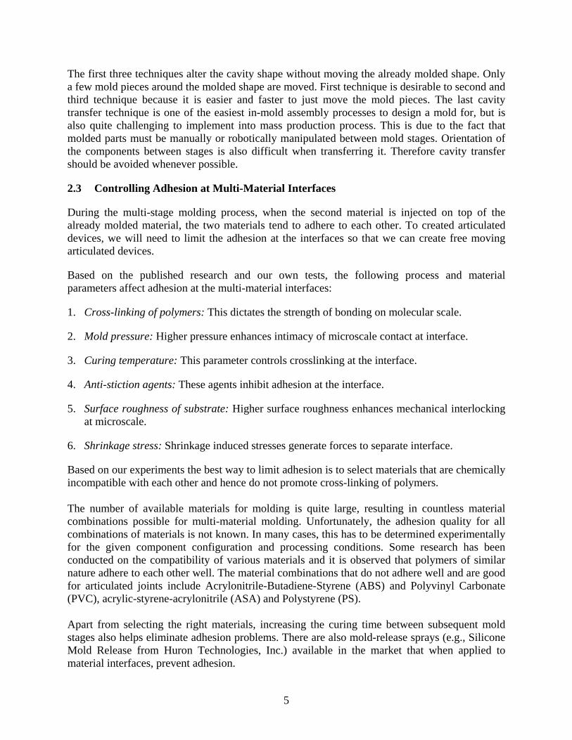
The first three techniques alter the cavity shape without moving the already molded shape. Only a few mold pieces around the molded shape are moved. First technique is desirable to second and third technique because it is easier and faster to just move the mold pieces. The last cavity transfer technique is one of the easiest in-mold assembly processes to design a mold for, but is also quite challenging to implement into mass production process. This is due to the fact that molded parts must be manually or robotically manipulated between mold stages. Orientation of the components between stages is also difficult when transferring it. Therefore cavity transfer should be avoided whenever possible.
2.3 Controlling Adhesion at Multi-Material Interfaces
During the multi-stage molding process, when the second material is injected on top of the already molded material, the two materials tend to adhere to each other. To created articulated devices, we will need to limit the adhesion at the interfaces so that we can create free moving articulated devices.
Based on the published research and our own tests, the following process and material parameters affect adhesion at the multi-material interfaces:
1. Cross-linking of polymers: This dictates the strength of bonding on molecular scale.
2. Mold pressure: Higher pressure enhances intimacy of microscale contact at interface.
3. Curing temperature: This parameter controls crosslinking at the interface.
4. Anti-stiction agents: These agents inhibit adhesion at the interface.
5. Surface roughness of substrate: Higher surface roughness enhances mechanical interlocking at microscale.
6. Shrinkage stress: Shrinkage induced stresses generate forces to separate interface.
Based on our experiments the best way to limit adhesion is to select materials that are chemically incompatible with each other and hence do not promote cross-linking of polymers. The number of available materials for molding is quite large, resulting in countless material combinations possible for multi-material molding. Unfortunately, the adhesion quality for all combinations of materials is not known. In many cases, this has to be determined experimentally for the given component configuration and processing conditions. Some research has been conducted on the compatibility of various materials and it is observed that polymers of similar nature adhere to each other well. The material combinations that do not adhere well and are good for articulated joints include Acrylonitrile-Butadiene-Styrene (ABS) and Polyvinyl Carbonate (PVC), acrylic-styrene-acrylonitrile (ASA) and Polystyrene (PS). Apart from selecting the right materials, increasing the curing time between subsequent mold stages also helps eliminate adhesion problems. There are also mold-release sprays (e.g., Silicone Mold Release from Huron Technologies, Inc.) available in the market that when applied to material interfaces, prevent adhesion.
5

3 Related Work
Several processes are being developed for concurrently performing fabrication and assembly. In this section, we review solid free form fabrication based techniques for manufacturing articulated structures that eliminate need for post fabrication assembly.
Shape deposition manufacturing (SDM) is being used to fabricate multi-material parts [Bail99, Merz94, Raja01]. In SDM, by varying the materials used in the deposition process, spatial variation in the material properties of the part can be achieved. SDM has been used to fabricate heterogeneous structures that consist of Steel and Copper, Embedded Electronics, Integrated Assemblies, and Biomimetic Robotic Mechanism. Manufacturability of SDM objects is achieved by composing these objects using SDM manufacturing primitives [Binn98]. Rajagopalan et al. [Raja01] and Cham et al. [Cham99] provide additional details on manufacturing of assembly-free structures. SDM process is suitable for small batch manufacturing.
Multi-material selective laser sintering (MMSLS) has been developed to fabricate functionally gradient material (FGM) objects [Beam00, Jeps99, Park99]. This process can also be used to make articulated structures. However, this process is not suitable for polymer processing.
Another layered manufacturing process, which is capable of producing articulated structures is 3D Printing [Jack98, Wu00]. Locally composition control components are fabricated by printing different materials in different locations, each through its own ink-jet nozzles. Jack at el. have discussed design rule governing the maximum and minimum material composition for the FGM parts [Jack99]. This process does not work with thermoplast materials and joints need to have large clearances for this process to create articulated joints.
Multi-material molding has been used to successfully create compliant mechanisms [Gouk05]. This work utilizes adhesion at the interfaces to join hard and compliant materials to form compliant joints. This paper describes feasible mold designs for creating different types of compliant joints found in multi-material compliant mechanisms. It also describes guidelines essential to successfully utilizing the multi-material molding process for creating compliant mechanisms. Finally, practical applications for the use of multi-material molding to create compliant mechanisms are demonstrated.
4 Designing Assemblies and Molding Process for Achieving Desired Joint Clearances
Currently a systematic approach to designing articulated assembly and molding process does not exist. It is an iterative process and successful implementation mainly depends on the designer’s experience. Figure 4 shows how shrinkage during the second molding stage generates clearances in the assembly. Estimating shrinkage for molded parts is a challenging problem in the molding community. This problem is extremely important in articulated assemblies because all the components have to fit together and work. Uncompensated shrinkage in even one component can cause the assembly to have excessive or insufficient clearances.
This section describes a model for designing assemblies and molding process so that the final product can meet the performance goals. We outline a systematic approach that will help a designer to determine part dimensions, material properties, and molding parameters.
6

Shrinkage is defined as the difference in dimensions of a molded part and the mold cavity at room temperature. Uncompensated shrinkage leads to either sink marks or voids in the molding interior. Shrinkage of individual components can stackup or combine together to affect a final assembly dimension. We describe shrinkage analysis, similar to the assembly tolerance analysis to help predict the final assembly dimensions and hence the success of an in-mold assembly. For the success of an assembly, there are some critical dimensions that need to be controlled. A critical assembly dimension Ys is a function of the component feature dimensions xi, and is given by:
Ys=f(x1, …, xn) (1)
This function between the assembly and component dimensions is known as assembly function or stackup function and must be derived for each assembly. Shrinkage analysis for assemblies is concerned with determining the critical assembly dimension Ys. This analysis will be illustrated with the help of a simple revolute joint shown in Figure 5. The clearance between the pin and the hole is a critical dimension and is given by:
C = Dh – Dp (2)
where Dh and Dp are the hole and pin diameters respectively. The component dimensions Dh and Dp are obtained after shrinkage. Because of the dynamic nature of the molding process, estimating shrinkage is not straightforward. However hard we try, some uncertainty will always be present. So we represent the component dimensions as interval numbers. For example, a dimension D will be represented as:
D = [Dmax, Dmin] (3)
The corresponding uncertainty in the clearance C can be calculated as follows:
Cmax = Dhmax – Dp
min (4)
Cmin = Dhmin - Dp
max (5)
ΔC = Cmax - Cmin = ΔDh + ΔDp (6)
The next step in shrinkage analysis is to understand the shrinkage of individual dimensions. Shrinkage of a dimension can be mathematically expressed as:
S = α.D (7)
where D is the original dimension and α is the shrinkage coefficient. The shrinkage coefficient α is dependent on material properties and other process parameters such as melt temperature, mold temperature, injection pressure and hold time. This parameter is usually experimentally determined for a given material and process parameters by creating a test specimen with the volume and section thickness comparable to the desired part. [Jans98] presented a systematic study on the effect of processing conditions on mold shrinkage. They concluded that the shrinkage of injection molded products is mostly influenced by the holding pressure and the melt temperature. [Post05] recently published experimental results on assessment of the effects of
7

process parameters on shrinkage. These studies can also be utilized to estimate the shrinkage coefficient for a given material and process parameters. After shrinkage, the dimension of a molded part Dp is given by:
Dp = (1-α)Dpm (8)
where Dpm is the mold dimension. The uncertainty in the molded part dimension can be
estimated as:
ΔDp = Δα.Dpm (9)
where Δα is the uncertainty in α, which can be controlled by changing molding parameters such as injection pressure, pack-hold time or cooling time, and holding pressure. The uncertainty in the mold dimension due to machining is negligible. Therefore, these terms are omitted from further consideration. From the above equation we get the following governing equations:
C = (1-αh)Dhm – (1-αp)Dp
m (10)
ΔC = ΔαhDhm + ΔαpDp
m (11)
where Dhm and Dp
m are the mold dimensions for the hole and pin respectively. Usually C and ΔC are given based on design goals. It is the job of the designer to determine the values for αh, αp, Δαh, Δαp, Dh
m, and Dpm that meet the given values of C and ΔC. As is obvious from Equations 10
and 11, the number of variables is more than the number of equations. Therefore this problem is under-constrained. These equations can be solved by assigning fixed values to some variables and solving for the remaining variables. The above equations have been derived for a revolute joint shown in Figure 5. Similar types of equations can be derived for other types of joints as well.
The above model is intended as a useful guideline for designing articulated assemblies and molding process. It usually provides a first order approximation. In many cases, shrinkage is not linear and constant in different directions. It is usually measured along three directions – direction of flow, cross-flow direction, direction of part thickness. These often may have different magnitudes leading to uneven volumetric shrinkage along the three directions. Moreover, in case of complex assemblies, it is very difficult to derive the assembly function. In such cases, shrinkage effects must be determined via empirical experiments.
Our experiments indicate that the following guidelines would be useful in controlling shrinkage in multi-stage molding process:
a. The outer components, which envelop the other components, must be cast before the inner components are molded. This will cause the last stage to shrink away from its preceding stage and establish clearance between the components. If the stage order is reversed, the final mold stage will tend to shrink onto the interior parts resulting in a friction increase at the interface, in turn restricting the relative motion.
8

b. Since shrinkage is directly proportional to component dimension, the above criterion may be ignored for small parts.
c. Pack-hold time or cooling time should be increased to reduce shrinkage.
d. Shrinkage can also be reduced by controlling injection pressure and melt temperature.
5 Mold Design Templates for Basic Joints
Articulated designs encompass a wide variety of geometrically interlocked surfaces depending on product requirements. While the type of interlocked surface is essentially up to the designer’s imagination, several common types of joint connections are currently used. These connections include -- prismatic, revolute and spherical joints. This section presents proven mold design templates for realizing the standard revolute, prismatic, and spherical joints. These mold design templates are very general and can be used with minor modification in other projects.
5.1 Prismatic Joints
Prismatic joints are seen in a wide variety of assembled objects. Applications range from the well-known slider-crank mechanisms, used in the cylinder of an internal combustion engine, to more recent mechanisms found in CD and DVD drives. The basic criterion to define a prismatic mechanism is that it restricts all rotational motion and allows the object to translate in one direction. This section presents two design templates for realizing prismatic joints. Both templates employ planar contact surface to constrain rotation and facilitate translation along one direction. The difference is in the geometry of the parts that form the prismatic joint.
In template A (Figure 6a), the handle completely envelops the slide. This design requires two molding stages, two mold pieces and a core. Figure 6b and 6c show the two mold stages for molding the prismatic joint. In the first mold stage, Mold piece A and B are assembled and the core is inserted to the position shown in Figure 6b. The first material is then injected into the assembled mold. Figure 6c shows the molded part after the first stage. For the second mold stage, the core pulled out to the position shown in Figure 6c. The second material is then injected to produce the final part.
In template B (Figure 7a), the handle partially envelops the slide. This design requires two molding stages and four mold pieces. Figure 7b and 7c show the two mold stages for the prismatic joint. In the first mold stage, the first material is injected into the assembly of mold piece A and B. Figure 7c shows the molded part after the first stage. For the second mold stage, the molded part produced in the first mold stage is transferred to the assembly of mold piece C and D as shown in Figure 7c. The second material is then injected to produce the final part.
Both prismatic joint templates follow the guidelines outlined in Section 4 of molding the inner component after the outer component. This will cause the inner component (slide) to shrink away from the outer component (handle) establishing clearance between the contact surfaces. However there are certain differences. Template A is simpler, but more restrictive than Template B. The geometry of the part containing the slide can only be modified at the ends. Template B offers more freedom than template A, but the mold design and operation is much more complex. It requires four mold pieces, while template A only requires two mold pieces and a simple core.
9
More importantly, template A employs a simple cavity manipulation technique where the core is simply pulled out of the previous mold stage, while template B employs the complex cavity transfer mechanism where the part is transferred form one mold stage to the next. This can have very serious implications on part quality. Careful analysis of shrinkage in the handle mechanism is required in order to ensure correct part alignment in the second mold stage. As seen in Figure 8a, the locking mechanism for the handle must perfectly align with the molded curvature for the slide. Figure 8b demonstrates how features of a part can become deformed if shrinkage is not accounted for. The slide will take on a deformed shape when molded. Despite the fact that the slide channel will shrink away from the handle after demolding, the part may not fully recover from this deformity. Consequently, the slide will suffer from tremendous friction loses and in extreme cases may be geometrically locked in place.
5.2 Revolute Joints
While combinations of translational or prismatic joints make up 3 DOF possible for joint connections, revolute joints encompass the other 3 DOF of purely rotational motion. Depending on the desired function, an articulated part may require 1 to 3 DOF for a revolute connection. Examples of these connections range from simple 1 DOF dimmer light switches to 3 DOF robotic arms. Pin connections are an excellent example of a simple revolute joint. These connections restrict all translational movements and only allow the part to rotate along one axis. When designing, one can combine several pin connections to increase the functionality of the part. This section presents two design templates for realizing revolute joint. Both design templates employ cylindrical contact surface to facilitate rotation along one axis but different features to constrain translation. One design template uses a cap-end connection while the other uses a groove connection.
Figure 9a shows template C with cap-end connection. This design requires two molding stages, two mold pieces and a core. Figure 9b and 9c show the two mold stages. In the first mold stage, Mold pieces A and B are assembled and the core is inserted to the position shown in Figure 9b. The first material is then injected into the assembled mold. Figure 9c shows the molded part after the first stage. For the second mold stage, the core is pulled out to the position shown in Figure 9c. The second material is then injected to produce the final part.
Figure 10a shows template D that uses a groove connection. This design requires two molding stages, three mold pieces and four cores. Figure 10b and 10c show the two mold stages. For the first mold stage core A1 is inserted into mold piece A and core A2 is inserted into mold piece C. Mold pieces A and C are assembled with mold piece B as shown in Figure 10b. First stage material is then injected. Figure 10c shows the molded part after the first stage. For the second mold stage, cores A1 and A2 are replaced with cores B1 and B2 respectively as shown in Figure 10c. The second material is then injected to produce the final part. Please note that Cores A1 and A2 have the same shape. They have been assigned different names to clearly illustrate the different assembly steps. Same is true with Cores B1 and B2.
Both revolute joint templates follow the guidelines outlined in Section 4 of molding the inner component after the outer component. This will cause the inner component to shrink away from the outer component establishing clearance between the cylindrical surfaces. However, it must be noted that the inner component also shrinks along the cylindrical axis. This might cause the cap
10

to stick to the outer component and jam the motion. Length of the inner component must be accordingly specified to compensate for this shrinkage. Although both templates provide similar functionality, design with the cap-end connection is better than the design with groove connection. The number of mold pieces are fewer and even the technique to alter the cavity shape after the first mold stage is much simpler. Only a slight translation of the core does the job.
5.3 Spherical Joints
Spherical joint allows for rotation in any direction simultaneously. A common example of this type of joint is known as the ball and socket joint. This type of joint is well known for its uses in the human body. There are many uses for the ball and socket joint in molded and assembled parts as well. Spherical joints are not widely used in molded plastic products because the joint needs to be realized by very precisely assembling many individual pieces. Therefore, instead of implementing a spherical joint, two or three pin connections are used in series to produce the same function.
In-mold assembly facilitates molding of spherical joints. A spherical socket requires a spherical core, which obviously cannot be disassembled from the molded socket. There are two options to disassembling the spherical core – using sacrificial core or splitting the core into three or more pieces. Using sacrificial core is costly and may not be suitable for many situations. Split cores introduce flash on the spherical surface that causes jerky motion. This section again presents two design templates for realizing spherical joints.
Figure 11a shows template E where the socket surrounds about three-fourth of the spherical ball. This design requires two molding stages, two mold pieces and five cores. Figure 11b and 11c show the different steps for molding the spherical joint. In the first mold stage, Mold pieces A and B are assembled with cores A, C1 and C2 as shown in Figure 11b. The first material is then injected into the assembled mold. Figure 11c shows the molded part after the first stage. For the second mold stage, the cores A, C1 and C2 are replaced by cores B1 and B2 as shown in Figure 11c. The second material is then injected to produce the final part.
Figure 12a shows template F where the socket surrounds the spherical ball only around the equator. This will enable the joint to have maximum rotational capabilities, but lesser mechanical strength. This design requires two molding stages, two mold pieces and 2 cores. Figure 12b and 12c show the different steps for molding the spherical joint. In the first mold stage, Mold pieces A and B are assembled with cores A and B as shown in Figure 12b. The first material is then injected into the assembled mold. Figure 12c shows the molded part after the first stage. For the second mold stage, the mold piece B is replaced by mold piece C, and the cores A and B are simply pushed out sideways as shown in Figure 12c. The second material is then injected to produce the final part.
Template E follows the guidelines outlined in Section 4 of molding the inner component after the outer component. This will cause the inner component (ball) to shrink away from the outer component (socket) establishing clearance between the contact surfaces. This template uses split cores, but still produces smooth motion. The trick to getting a smooth motion in spite of the flash produced by split cores is not molding the entire ball and socket. Both, ball and socket are split and there are two empty spaces on both of them. As the joint is rotated, the flash on the surface
11

will be pushed into those empty spaces causing a smooth motion. Template F is much simpler as compared to template E, but it molds the socket after the ball leading to a tighter clearance. This template requires uses of anti-stiction agents and materials with negligible shrinkage.
6 Mold Design Guidelines for Parts with Multiple Joints
The previous section described proven mold design templates for standard joints. This section will describe how to combine those templates to design molds for parts with multiple joints. Mold design can be formulated as a multi-objective optimization problem. The objectives of the mold design problem are as follows:
a. Minimize mold cost. The mold cost is directly proportional to the number of mold pieces, inserts and actuators. Most of these are largely dependent on the geometry of the part and the molding strategy. Inserts and actuators are required to form the undercuts on the part. In some cases, a smart change in geometry of the part can eliminate the undercuts on the part and hence the need for inserts. If the production volume is not very high, replacing the actuators by manually unloading the parts may be economical. Over-molding process increases the number of mold pieces by requiring multiple copies of the same mold piece. But at the same time, mold pieces for over-molding process are considerably simpler. So over-molding process must be chosen only after careful analysis.
b. Minimize molding cycle time. Higher the molding cycle time, higher the running cost. Molding time is mainly governed by the part cooling time and the cavity manipulation between two mold stages. Part cooling time can be reduced by appropriate material selection and mold cooling techniques. Cavity manipulation time can be reduced by choosing faster methods as explained in Section 2.2. Cavity transfer mechanism is the slowest and must always be avoided if possible.
c. Minimize part defects. Part defects very much dependent on the ability to precisely locate parts in the mold. As explained in Section 2.2, this becomes problematic in the over-molding process where parts have to be completely moved from one mold to another. From Section 4, to achieve desired part performance (i.e., acceptable joint clearances), the outer components must be cast before the inner components.
These objectives are fully or partly conflicting with each other. For example, removing the actuators reduce the mold cost but increase the molding cycle time. Therefore, mold design problem is solved by assigning weights or making tradeoffs among individual objectives. Different types of situations (e.g., prototyping, production runs, rush orders) require different weights for individual objectives. Given the part geometry, mold design can be performed in five steps:
a. Determine molding sequence: For each material in the desired product, a separate molding stage is required. A molding stage entails casting a single material in a specific mold configuration. Successive stages require reconfiguring the mold as well as the previously cast, and partially cured, stage. This step is most critical as it directly influences the subsequent mold design steps and material selection.
12

It is important to specify an appropriate sequence of stages so that the product can be manufactured in the least amount of stages. For example, a product with three materials has six different possible sequences. Of course the geometry of the part can limit the possible number sequences. For instance, a product that has one material completely encased another would require the inner material stage to be cast first. One way to minimize manufacturing time is by using a mold-staging strategy that involves casting as many materials in one sequence as possible. For example, consider the three-material object illustrated in Figure 13. Because materials A and C never touch, material B can be cast in the first stage and then A and C can be both cast in the second stage. Another important factor to consider here is joint clearance - the outer components must be cast before the inner components.
An additional rule needed for in-mold assembly using an injection molding is that the melting temperature of the first molded material must be much greater than the melting temperature of the material being used in the second molding stage. The same general rule holds true for all subsequent molding stages. The designer must match up material properties with mold stages as well as product specifications.
b. Determine gross mold geometry for each stage: For each stage, an appropriate gross mold has to be designed in order to produce the desired geometry. A gross mold is a simple block that contains an inner cavity, which could completely encase the desired object. Envisioning each stage of the product as a separate object and then using the gross geometry to form the basis for the mold cavity can produce the gross mold geometry. The mold cavity geometry is generated simply by a Boolean subtraction of the object from an adequate-sized stock piece. The stock piece should bound the object on all sides, while allowing adequate excess material outside of the object to act as the mold’s outer walls. Once a set of separate gross molds is specified for each stage, eliminating redundant pieces generates the actual set of mold pieces that will be used. If two or more molding stages share the same cavity, there is no need to make multiple copies of the cavity.
c. Determine mold partitions: Each gross mold must be split into a set of mold pieces that will allow the cured part inside to be removed. A careful analysis of the part geometry must be performed so that there will be no undercuts preventing the mold from opening. This may require the use of multiple mold pieces with complex staggered or angled parting lines.
Additionally, it is desired to partition the molds into mold pieces that can be reused between stages. This usually happens when at least part of a cavity is the same between both stages. In this case, the mold can be partitioned around the common part of the cavity. A final partitioning consideration involves a careful DFM analysis on each mold piece. Each piece should be configured so that it is machinable by a CNC milling machine in as few sequences as possible. Minimizing machining operations reduces manufacturing time as well as ensures a good fit between assembled mold pieces. We are currently using multi-piece, multi-material mold design software that automatically specifies mold partitions given a CAD model of the desired multi-material object [Priy04].
d. Design auxiliary mold features: After the molds have been partitioned into appropriate mold pieces, features have to be added to the mold geometry to allow the part to be actually cast. The first step is to incorporate some form of assembly features so that the mold pieces will
13

interlock and remain together during casting. These assembly features are usually some form of bosses and holes or slots, which fit into each other, constraining the pieces from moving. The exact nature of these features is unimportant as long as they provide adequate sealing between mold pieces. Of course it is desirable from a manufacturing point of view to minimize the complexity of such assembly features.
The second set of features that must be incorporated into the mold is a material gating system. Usually, a gate hole and several air outlets are added to the topmost mold piece on the top surface. This allows the molding material to flow into and fill the entire cavity as well as allowing air pockets to escape up out of the mold. If these important flow considerations are neglected, the final product will be incompletely filled, resulting in air bubbles in the molded part.
7 Case Studies
We have developed a multi-stage molding process to produce multi-material articulated devices. Our process creates non-binding strictly geometric interfaces to allow for selective degrees of freedom between components. In essence, the process utilizes multi-piece, multi-stage polymer molds that are used to mold either low-pressure, room-temperature-curing binary polyurethane (PUR) compounds or thermoplasts. The mold designs for these case studies have been carried out by utilizing the six mold design templates (A-F) for standard joints presented in Section 5 and the guidelines presented in Section 6.
7.1 Flip Cover
Telecommunications, especially the cell phone industry, is a rapidly growing industry requiring many new molding technologies. One of the main focuses for new molding technologies is to make smaller phones. In-mold assembly promotes size reduction; therefore, the example of the hinge connection we choose to create resembles one found at the end of a flip cell phone. This example has a revolute joint with 1 DOF along the rotational axis. Figure 14 shows the CAD model for the flip cover and the physical part. The mold design for the flip cover is a variation of the revolute joint with cap-end connection (template C). The flip cover was molded in two stages. To ensure clearance between the pin and hole, the base of the hinge that contains the hole was molded in the first stage, while the cover with the pin was molded in the second stage. Both cover and base were made using IE-72DC material, a kind of polyurethane from Innovative Polymers, Inc. with 0.4% shrinkage coefficient. Satisfactory results were obtained for pin diameter 0.125 inches. By varying the pin diameters and selecting a material with a different shrinkage value, the amount of clearance can be altered. Reducing the mold cycle time was the driving force behind other design decisions. We opted for fast cavity shape change method where two cores were simply pulled out and one core was replaced by another. Most of the mold pieces were common between the two mold stages. 7.2 Gimbal
14

The most prominent example of the pin connection is seen in the gimbal model. This mechanism has a total of four pin connections allowing rotation along two axis giving the part 2 DOF. Figure 15 shows the various orientations attained by gimbal.
Gimbal is made up of three parts, but still can be made in two stages. As explained in Section 6, if two parts A and B touch another part C, but not each other, then part C can be molded in the first stage and both parts A and B can be molded simultaneously in the second stage. So in this case minimizing the number of mold stages drove our mold design. The part shown in Figure 15 has two 0.13 inch revolute joint. It uses a variation of the revolute joint with cap-end connection (template C). The middle ring was molded in the first stage, and the outermost and innermost rings were molded in the second stage. We found that as a result of the shrinkage of the outermost and innermost rings, the part had satisfactory clearance values to enable joint motion. The material combination used for this design was IE-72DC material, a kind of polyurethane from Innovative Polymers, Inc. and Polyethylene.
7.3 Rotor
To demonstrate how several simple in-mold assembly connections can be combined to replace complex assemblies, the model of a novel unmanned air vehicle (UAV) rotor was created. This example clearly demonstrates how multi-material designs can drastically reduce the number of parts required for a design, while still maintaining functionality and in many cases even increasing the range of motion. It also demonstrates how complex systems are designed using innovative methods to improve the efficiency. We show how a complex assembly can be replaced by a multi-material assembly, which requires no secondary assembly operations. We also show how the spherical joint templates described in Section 5 can be used together in a complex multi-material assembly. This original model incorporated many linkages, pin connections and ball and socket joints in order to control the actuation of each of the rotor functions. The original design consisted of 30 parts and required many assembly steps. Also, many parts to be assembled were quite small making assembly very difficult and tedious. The exploded view of the original model is shown in Figure 16a. We already know that in most assembly situations the part count is directly related to the probability for failure. As the part count increases, the number of defective parts will increase. Also the amount of interface surfaces between joint connections increases, thus increasing the probability of failure along these surfaces as well. The part count is also directly related to the assembly time. So, the driving factor behind the redesign of the rotor was to reduce the part count and simplify the interface geometry. The rotor primarily has three functions - rotate, pitch and roll the blades. We designed three actuation plates to control each motion. Including the two blades, this reduces the part count to five (Figure 16b). The mold design consists of 4 stages and 18 mold pieces. We could have reduced the number of mold pieces at the expense of the geometric complexity of mold pieces. But we were interested in prototyping only 5 copies of the part so we opted for a simpler design with many mold pieces. The first actuation plate is essentially the base or ground of the system, this plate will control the rotation of the entire system. This plate will be attached to a center rod, which is attached
15

directly to the top of the helicopter, or in the case of this example a basic power source/gear box. The blades are attached to this plate through two spherical joints (template F) that allow rotation along both x and y axes. As mentioned in Section 5.3, template F is simple but allows very little clearance because it molds the socket after the ball. Since we were only interested in prototyping, we chose template F because of its simplicity. We controlled the clearance by applying a thin layer of lubricant to the ball (base) before molding of the socket and choosing the socket (blade) material with small shrinkage coefficient. We chose IE-72DC material, a kind of polyurethane from Innovative Polymers, Inc for the base and the blades. The second actuation plate contains the pitch control. For this control, the blades are required to rotate about the x-axis. The challenge in designing this simple joint comes from rotation about the center axis requirement and that the connection cannot limit the blades’ ability to rotate about the y-axis. This function was obtained through a spherical ball and socket connection (template E). Notice, this design mimics the original design method of actuation, controlled by the vertical movement of the actuation plate. The third actuation plate controls the roll of the blades. For this control, the blades are required to rotate about the y-axis. Again this is essentially a 1 DOF revolute joint for each blade; however, the actuation of this particular joint is slightly more difficult. Since this part rotates about a center axis, we must think of the axis moving with the part in rotation. Using this visualization scheme one can see that an additional actuation point is required to rotate about the y-axis. Since the original design requires actuation upon movement of the center rod, a linkage connection is implemented to connect both actuation points. New actuation points have been created along one side of each blade. These actuation points are then connected to a center rod actuation point via a diagonal bar. For this particular movement, a ball and socket joint (template E) is used. The final part, shown in Figure 16c, has six ½ inch spherical joints and a blade span of 5 inches. The dimensions of the joint and the material combination provided satisfactory joint clearance. Figure 17 shows both the original and the redesigned rotor side-by-side in action. 8 Conclusions
In this paper, we presented a model for designing assemblies and molding process so that the joint clearance and variation in the joint clearance can meet the performance goals. We outlined a systematic approach that will help a product designer determine part dimensions and material properties. We presented proven mold design templates for realizing revolute, prismatic, and spherical joints. We described an overall mold design methodology for designing molds for products that contain articulated joints and will be produced using in-mold assembly process. Finally, we described three case studies to illustrate how in-mold assembly process can be used to create articulated devices. In this paper we have discussed a wide variety of articulated joints; however this list is not all inclusive. Other types of joints that have not been explored for in-mold assembly articulated designs include, screw joints, gear joints, and linkages. Screw joints specify the rotation of one part about an axis, as the part translates along the axis with respect to a second part. Gears relate the motion of three parts and two joints. Different types of gear joints commonly used are spur, helical, planetary, bevel, and rack-and-pinion gears. Linkages primarily add alternate axis of motion to the part being designed. By including linkages into a part one may change the
16

direction of motion, or change the linear scaling between critical interfaces. This will also increase the complexity of the in-mold assembly process. In addition to the development of in-mold assembly processes for these types of joints, more development can be focused on combinations of multiple joints. The rotor example illustrates the drastic improvement that can be realized through in-mold assembly joints, in both part count and assembly time. More research should be done to focus on these complex problems and how to implement them into the variety of standard molding processes seen in industry today. In the future we plan to implement these three basic joint principles into more complex assemblies. We will emphasize on in-mold assembly processes that do not require cavity transfer, as they are easier to adapt in industrial processes. A more detailed analysis of shrinkage parameters vs. geometrical interfaces would also be beneficial. This analysis could be used to develop rules for over-molded parts to reduce the number of iterations for the rapid prototype tests. Acknowledgements. This research has been supported in part by NSF grants DMI0093142 and EEC0315425, and Army Research Office through MAV MURI Program (Grant No. ARMY-W911NF0410176). Opinions expressed in this paper are those of authors and do not necessarily reflect opinion of the sponsors. References
[Anan95] G.K. Ananthasuresh and S. Kota. Designing Compliant Mechanisms. Mechanical Engineering, 117(11): 93-96, 1995.
[Bail99] S.A. Bailey, J.G. Cham, M.R. Cutkosky, and R.J. Full. Biomimetic Robotic Mechanisms via Shape Deposition Manufacturing. 9th International Symposium of Robotics Research, Utah, October 1999.
[Beam00] J. Beaman, D. Bourell, B. Jackson, L. Jepson, D. McAdams, J. Perez, and K. Wood. Multi-Material Selective Laser Sintering: Empirical Studies and Hardware Development. NSF Design and Manufacturing Grantees Conference, January 2000.
[Binn98] M. Binnard and M. R. Cutkosky. Building block design for layered shape manufacturing. In Proceedings of the ASME Design for Manufacturing Conference, Atlanta, GA, September 1998.
[Bruc04] H. Bruck, G. Fowler, S.K. Gupta, and T. Valentine. Towards bio-inspired interfaces: Using geometric complexity to enhance the interfacial strengths of heterogeneous structures fabricated in a multi-stage multi-piece molding process. Experimental Mechanics, 44(3):261--271, 2004.
[Bryc96] D. M. Bryce. Plastic Injection Molding, Vol. I: Manufacturing Process Fundamentals. Society of Manufacturing Engineers: Dearborn, Michigan, 1996.
[Cham99] J. G. Cham, B. L. Pruitt, M. R. Cutkosky, M. Binnard, L. Weiss, and G. Neplotnik. Layered Manufacturing with Embedded Components: Process Planning Issues. In Proceedings of the ASME Design for Manufacturing Conference, Las Vegas, NV, September 1999.
17

[Good02] V. Goodship and J.C. Love. Multi-Material Injection Moulding. Rapra Technology LTD.: Shawbury, UK, 2002.
[Gouk05] Regina M. Gouker, Satyandra K. Gupta, Hugh A. Bruck, and Tobias Holzschuh. Manufacturing Of Multi-Material Compliant Mechanisms Using Multi-Material Molding. Accepted for Publication in International Journal of Advanced Manufacturing Technology, 2005. [Jack98] T. R. Jackson, E. M. Sachs, and M. J. Cima. Modeling and Designing Components with Locally Controlled Composition. In Proceedings of the Solid Freeform Fabrication Symposium, August 1998.
[Jack99] T. R. Jackson, H. Liu, N. M. Patrikalakis, E. M. Sachs, and M. J. Cima. Modeling and Designing Functionally Graded Material Components for Fabrication with Local Composition Control. Materials and Design, vol. 20, no. 2/3, pp. 63--75, June 1999.
[Jans98] K.M.B. Jansen, D.J. Van Dijk, and M.H. Husselman. Effect of Processing Conditions on Shrinkage in Injection Molding. Polymer Engineering and Science, vol. 38, no. 5, pp. 838-846, May 1998.
[Jeps99] L. Jepson, J. Perez, J. Beaman, D. Bourell, and K. Wood. Development of multi-material selective laser sintering process. In Proceedings NSF Design and Manufacturing Grantees Conference, Long Beach, CA, January 1999.
[Li04] X. Li and S.K. Gupta. Geometric algorithms for automated design of rotary-platen multi-shot molds. Computer Aided Design, 36(12):1171--1187, 2004.
[Mall94] R. A. Malloy. Plastic Part Design for Injection Molding: And Introduction. Hanser Gardner Publications, Inc.: Cincinnati, Ohio, 1994.
[Merz94] R. Merz, F.B. Prinz, K. Ramaswami, M. Terk, and L. Weiss. Shape deposition manufacturing. In Proceedings of the Solid Freeform Fabrication Symposium, Austin, TX, 1994.
[Park99] S. M. Park, R. H. Crawford, and J. J. Beaman. Functionally gradient material design and modeling using hypertexture for solid freeform fabrication. In Proceedings of the Solid Freeform Fabrication Symposium, Austin, TX, August 1999.
[Pirk98] J. D. Pirkl. Automating the Multi-Component Molding Process. In Proceedings of Technologies for Multi-Material Injection Molding (CM98-206). Troy, Michigan, May 1998.
[Plan02] H. Plank. Overmolding-Stack-Mold Technology: An Innovative Concept in Multi-Component Injection Molding. SME Technical Papers (CM02-225), 2002.
[Post05] P. Postawa. Shrinkage of Moldings and Injection Molding Conditions. Polimery 50(3): 201-207, 2005
[Priy04] A. Priyadarshi, and S.K. Gupta. Geometric algorithms for automated design of multi-piece permanent molds. Computer Aided Design, 36(3): 241-260, 2004.
18
[Raja01] S. Rajagopalan, R. Goldman, K.H. Shin, V. Kumar, M.R. Cutkosky, and D. Dutta. Representation of heterogeneous objects during design, processing and freeform-fabrication. Materials & Design, 22 (3): 185-197 MAY 2001.
[Roth04] J. Rotheiser. Joining of Plastics, Handbook for Designers and Engineers. Hanser Gardner Publications, Inc.: Cincinnati, Ohio, 2004.
[Wu00] H. Wu, E. M. Sachs, N. M. Patrikalakis, D. Brancazio, J. Serdy, T. R. Jackson, W. Cho, H. Liu, M. Cima, and R. Resnick. Distributed Design and Fabrication of Parts with Local Composition Control. In Proceedings of the NSF Design and Manufacturing Grantees Conference, Vancouver, Canada, January 2000.
19

(a) – articulated toys (b) – one-piece syringe
Figure 1: Examples of in-mold assembled products
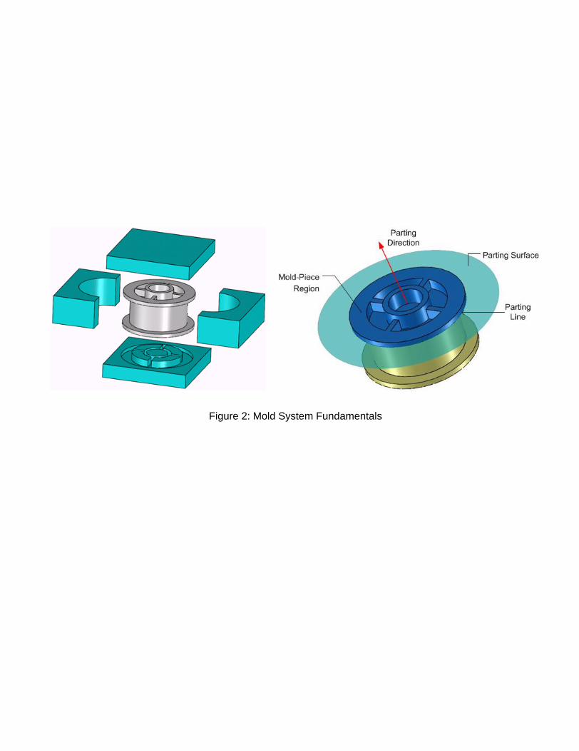
Figure 2: Mold System Fundamentals

(a) moving a mold piece (b) changing a mold piece (c) removing partition
Figure 3: Examples of Different Ways to Change Cavity Shape During Second Stage
Cavity shape after completing first stage
Cavity shape before starting second stage
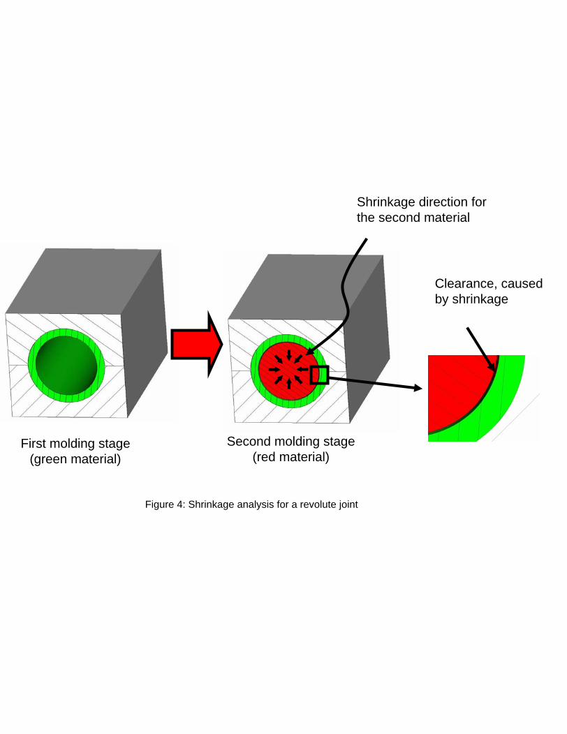
Clearance, caused by shrinkage
First molding stage(green material)
Second molding stage(red material)
Shrinkage direction for the second material
Figure 4: Shrinkage analysis for a revolute joint

Figure 5: Shrinkage analysis for a revolute joint

Mold piece A
(b) First mold stage
Mold piece B
Core
Part created in first mold stage
Part created in second mold stage
(a) Part Design
(c) Second mold stage
Mold piece B
Core
Mold piece A
Part created in first mold stage
Figure 6: Prismatic Joint (Template A)

(b) First Mold Stage
Mold AMold B
(c) Second Mold Stage
Mold C
Mold D
Part created in first mold stage
(d) Physical Part
Figure 7: Prismatic Joint (Template B)
(a) Part Design

(a) Critical surface for shrinkage
(b) Deformation created by excessive shrinkage
Figure 8: Effect of excessive shrinkage on part quality

(b) First mold stage
Mold piece B
Core A
Mold piece A
Mold piece B
Core A
Mold piece APart created in first mold stage
(c) Second mold stage
(a) Part Design
Part created in first mold stage
Part created in second mold stage
(d) Physical part
Figure 9: Revolute joint with cap-end connection (Template C)

Figure 9a: Part Design
Part created in first stage
Part created in second stage
Figure 9d: Physical part
Figure 9b: First mold stage
Core A1 Core A2
Mold piece A
Mold piece B
Mold piece C
Figure 9c: Second mold stage
Part created in first mold stage
Core B1Core B2
Figure 10: Revolute joint with groove connection

(a) Part Design
Part created in first mold stage
Part created in second mold stage
(d) Physical part
(b) First mold stage
Mold piece B
Mold piece A
Core A Core C1
(c) Second mold stage
Core B
Part created in first mold stage
Figure 11: Spherical joint (Template E)

(a) Part Design
Part created in first mold stage
Part created in second mold stage
(d) Physical part
(b) First mold stage
Mold piece A Mold piece B
Cores A and B
(c) Second mold stage
Mold piece C
Part created in the first mold stage
Figure 12: Spherical joint (Template F)

Figure 13: A 3 material assembly manufacturable in 2 molding stages
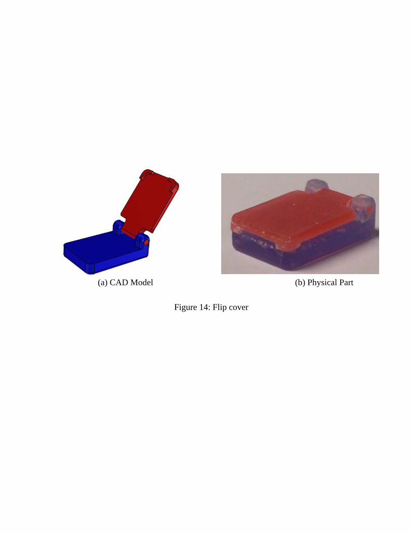
Figure 14: Flip cover
(a) CAD Model (b) Physical Part

Figure 15: 2 DOF movement achieved with the gimbal assembly

(b) Redesigned rotor system, aerial view (left), cut view (right)
Second actuation plate
Third actuation plate
z
yx
First actuation plate
(c) Physical part
Figure 16: Original metal assembly and redesigned rotor system
(a) Original metal assembly, exploded view

Figure 17: Various rotor positions, original model (left), multi-material molded assembly (right)