this document was originally for official use only
TRANSCRIPT

This document was originally For Official Use Only.
EMERGENCY RESPONSE COMMUNICATIONS
INTEROPERABILITY
(ERCI)
AFTER INITIATIVE REPORT
12 November 2003

PREFACE
This report is an overview of the objectives, activities, and events of the Force Protection Battlelab’s (FPB’s) Emergency Response Communications Interoperability (ERCI) Battlelab Initiative (BI) designed to prove the concept of seamless interoperability among radio systems operating on different frequencies and bands. This effort was accomplished through a series of field tests.
Presented By: _____________________________ ANTHONY D. MARTIN, MSgt, USAF NCOIC, Anti/Counter Terrorism Branch Force Protection Battlelab Reviewed By: _____________________________ JAMES A. LAWSON Jr, Maj, USAF Chief, Antiterrorism/Counterterrorism Division Force Protection Battlelab Approved By: _____________________________ TOMMY DILLARD, JR., Colonel, USAF Commander Force Protection Battlelab
DISTRIBUTION: Distribution authorized to US Government agencies and their contractors only. Other requests for this document must be deferred to the Commander, USAF Force Protection Battlelab, 1517 Billy Mitchell Blvd, Lackland AFB TX 78236-0119 AUTHORITY: Authority for this report is AFI 10-1901.
EMERGENCY RESPONSE COMMUNICATIONS INTEROPERABILITY AFTER INITIATIVE REPORT
2

THIS PAGE INTENTIONALLY LEFT BLANK
EMERGENCY RESPONSE COMMUNICATIONS INTEROPERABILITY AFTER INITIATIVE REPORT
3

SECTION TABLE OF CONTENTS EXECUTIVE SUMMARY 1. DEMONSTRATION MIS
1.1 PURPOSE 1.2 BACKGROUND 1.3 REQUIRED ASSET
2. COURSE OF ACTION
2.1 DEMONSTRATIO2.2 STRATEGY TO AC2.3 METHODS OF ME2.4 TEST PHASE 2.5 DATA REDUCTIO
3. RESULTS
3.1 GENERAL 3.2 OBJECTIVES 3.3 OBSERVATIONS
4. RECOMMENDATIONS
4.1 GENERAL 4.2 SPECIFIC DEFICIE4.3 SPECIFIC RECOM
LIST OF FIGURES
ATTACHMENTS
EMERGENCY RESPONSE COMMUNI
TABLE OF CONTENTS
4
6
SION STATEMENT 8
8 8
S 11
14
N OBJECTIVES 14 HIEVE 14
ASUREMENT 14 16
N AND ANAYLSIS 16
18
18 18 18
31
31 NCIES 31
MENDATIONS 31
32
33
CATIONS INTEROPERABILITY AFTER INITIATIVE REPORT 4

THIS PAGE INTENTIONALLY LEFT BLANK
EMERGENCY RESPONSE COMMUNICATIONS INTEROPERABILITY AFTER INITIATIVE REPORT
5

PURPOSE The purpose of this initiative was tointeroperability capability.
BACKGROUND Homeland security requirements diceffectively respond to terrorist threaduring operations outside the continmilitary, state, local and federal agenincident whether naturally occurringinteroperable voice communications
COURSE OF ACTION
This initiative was conducted as a prThe objectives were: (1) Evaluate thcapability (2) Evaluate the utility offor homeland defense. RESULTS The Emergency Response Communthe concept of a cross band, cross plIncident Commander’s Radio Interfa RECOMMENDATIONS The Incident Commander’s Radio Inallows a rapid communication link bRecommend a requirement for the eand Procedures, under paragraph 4.5allowance for all first responder pers
EMERGENCY RESPONSE COMMUNIC
EXECUTIVE SUMMARY
evaluate the utility of a cross band, cross platform radio
tate a solution to interoperability of radio systems to ts and natural disasters within the United States as well as ental United States. Interoperable communications between cies is key to efficiently and effectively responding to an or manmade. Additionally, forward deploying units require during contingency operations.
oof of concept demonstration in an operational environment. e utility of a cross band, cross platform radio interoperability a cross band, cross platform radio interoperability capability
ications Interoperability (ERCI) initiative was able to prove atform radio interoperability capability through the use of the ce (ICRI).
terface is an effective, low cost piece of equipment that etween military, state and local first responders. quipment be placed in AFI 31-201, Security Police Standards . Further recommend this equipment be placed on table of onnel.
ATIONS INTEROPERABILITY AFTER INITIATIVE REPORT 6

EMERGENCY RESPONSE COMMUNICATIONS INTEROPERABILITY AFTER INITIATIVE REPORT
7

THIS PAGE INTENTIONALLY LEFT BLANK
EMERGENCY RESPONSE COMMUNICATIONS INTEROPERABILITY AFTER INITIATIVE REPORT
8

1.1 PURP The purpose of interoperabilityband, cross platcross platform r 1.2 BACK Homeland secueffectively respduring operatiomilitary, state, lincident whetheemergency resparrive at the scefrequencies. Hoalong with systenot being able tfor a device thathat can link difvariables such alarge operation.the Incident Coand easy of opeissues of first redemonstration aApplied Technosetup device thainteroperabilitytogether can proresources to modesigned to proand the ICRI ca“nets” can be optogether withoufunctions: Distrecording devicradios connectethat delays are nand/or recordin
EMERGENCY RE
1. DEMONSTRATION MISSION STATEMENT
OSE
this initiative was to evaluate the utility of a cross band, cross platform radio capability. The specific areas of focus were: (1) Evaluate the utility of a cross form radio interoperability capability. (2) Evaluate the utility of a cross band, adio interoperability capability for homeland defense.
GROUND
rity requirements dictate a solution to interoperability of radio systems to ond to terrorist threats and natural disasters within the United States as well as ns outside the continental United States. Interoperable communications between ocal and federal agencies is key to efficiently and effectively responding to an r naturally occurring or manmade. The number one problem in large-scale onse is communications between incident commanders and the responders that ne. Most responding agencies have their own communications equipment and wever, the equipment and frequencies vary from agency to agency. This ms such as encryption devices and radio trunking causes the problem of
o communicate with other first responder agencies. This creates a need t can link several types of communications systems together. A device ferent types of radio equipment that use different frequencies and or s trunking or encryption together could prove crucial to the success of a Several solutions are commercially available to address radio interoperability but mmander’s Radio Interface (ICRI) rigid construction, low cost, quick setup time ration with limited training most effectively address interoperable communication sponders. For these reasons the Force Protection Battlelab choice it as a nd experimentation platform. The ICRI is manufactured by Communications-logy of Reston, VA. The small (10”x3”x6”), portable (5 lbs.) ICRI is a quick t can provide two, three, four, or five public safety agencies with radio
as a tactical situation is rapidly unfolding before them. Two ICRI system linked vide up to ten radios with interoperability. The ICRI requires little manpower ve it into place and to maintain its operation over many hours. The ICRI was vide full operational capabilities in as little as one minute after arrival on-scene n remain operational for 24 hours on 8 “AA” batteries. Multiple ICRI-based erated during a single incident; multiple ICRI-based “nets” can be rapidly linked
t hand tool and/or adjustments. In simplest terms, the ICRI performs two primary ributes audio received from one two-way radio to other radios, telephone or e connected to the ICRI. Utilizes this same incoming audio to “key” the other d to the ICRI. The ICRI does not discriminate or evaluate the incoming audio so ot inserted into the audio transfer or “keying” processes. Radios, telephones
g devices connected to the ICRI are provided with the incoming essentially in
SPONSE COMMUNICATIONS INTEROPERABILITY AFTER INITIATIVE REPORT 9

real-time (an initial delay at keying to preserve the first syllables of incoming audio as the transmitters [including wide area, repeater based “trunked” radio systems] are keyed up). An ICRI contains up to six circuits that key the radios connected to the ICRI; these circuits are commonly referred to as “VOX” or “voice-activated switches.” The ICRI uses these circuits to perform other controlling functions as well. Only the VOX directly connected to the incoming audio is used to key each of the other radios simultaneously (all other are temporarily disabled, preventing a second “voice” from causing a disruption in initial voice being distributed). Figure 1
EMERGENCY RESPONSE COMMUNICATIONS INTEROPERABILITY AFTER INITIATIVE REPORT
10
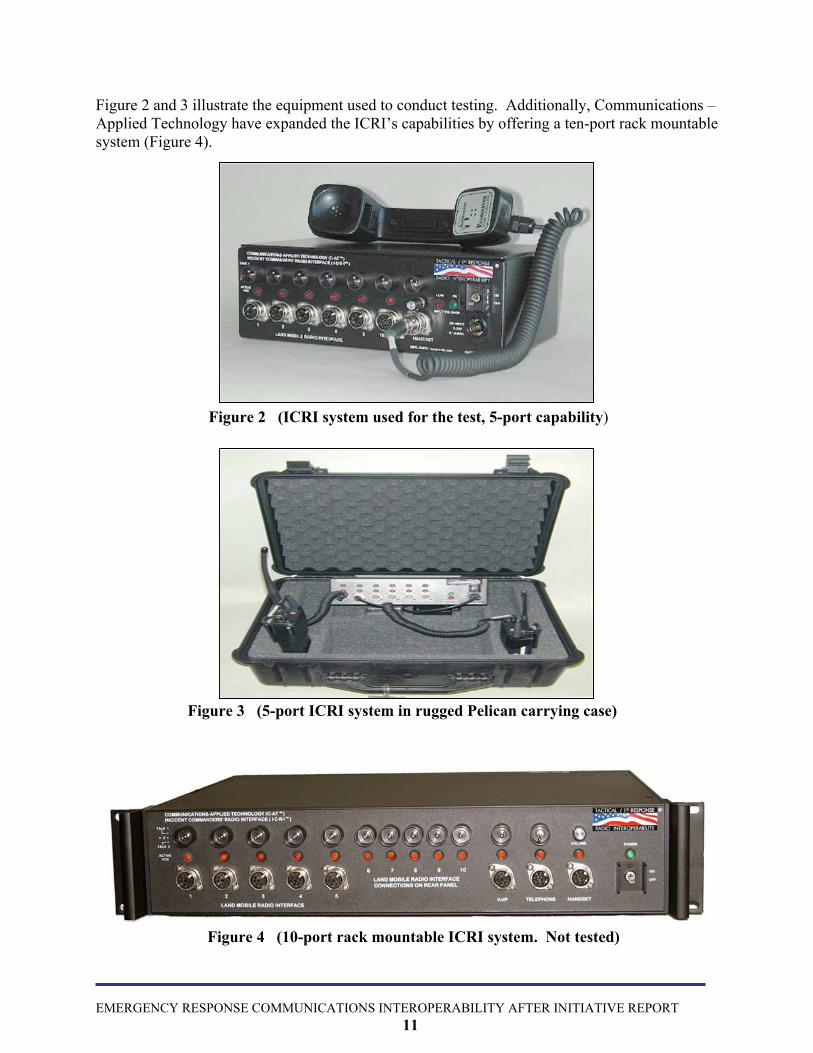
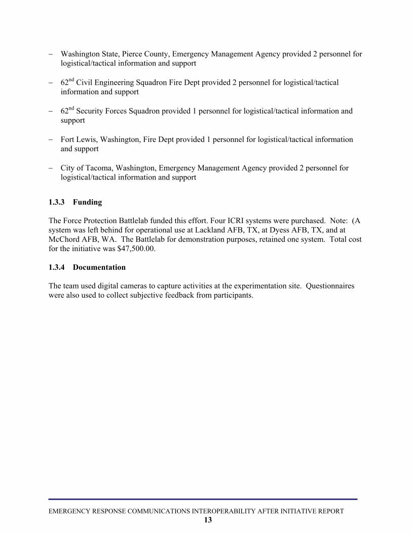
Figure 2 and 3 illustrate the equipment used to conduct testing. Additionally, Communications – Applied Technology have expanded the ICRI’s capabilities by offering a ten-port rack mountable system (Figure 4).
Figure 2 (ICRI system used for the test, 5-port capability)
Figure 3 (5-port ICRI system in rugged Pelican carrying case)
Figure 4 (10-port rack mountable ICRI system. Not tested)
EMERGENCY RESPONSE COMMUNICATIONS INTEROPERABILITY AFTER INITIATIVE REPORT
11

1.3 REQUIRED ASSETS 1.3.1 Battlelab Field Experiment Locations The ICRI Battlelab Field Experiment (BFX) was conducted at the following locations: Abilene Police Department Communictions Center, Abilene TX, Dyess AFB, TX, Pentagon, Washington DC, Wilford Hall Medical Center, Lackland AFB, TX, McChord AFB, WA and Colorado Springs Airport, CO. 1.3.2 Personnel Requirements The following US Air Force personnel executed the initiative: − MSgt Tony Martin, (USAF) USAF Force Protection Battlelab, NCOIC, Anti/Counter
Terrorism Branch and Project Officer for the initiative − Mr. Donald Lowe, (USAF) USAF Force Protection Battlelab, Assistant Project Officer. − Maj James Lawson, (USAF) USAF Force Protection Battlelab, Division Chief, Anti/Counter
Terrorism Branch − Capt Dave Skiba, (USAF) USAF Force Protection Battlelab, Explosive Ordnance Disposal
Officer The following organizations provided expertise and support during the BFX: − Abilene Police Department, TX, provided 4 patrol officers, 2 radio communications specialist − 7th Civil Engineering Squadron, Readiness Flight provided two personnel for
logistical/tactical information and support − 7th Communications Squadron provided two personnel for communication support − Pentagon Force Protection Agency, provided two personnel for logistical/tactical information
and support − Arlington Fire Dept, VA, provided two personnel for logistical/tactical information and
support − Communications – Applied Technology provided one ICRI system expert − Air Force Space Command, Civil Engineering, provided 2 personnel for logistical/tactical
information and support − 62nd Communications Squadron provided one person for communication support
EMERGENCY RESPONSE COMMUNICATIONS INTEROPERABILITY AFTER INITIATIVE REPORT
12
− Washington State, Pierce County, Emergency Management Agency provided 2 personnel for logistical/tactical information and support
− 62nd Civil Engineering Squadron Fire Dept provided 2 personnel for logistical/tactical
information and support − 62nd Security Forces Squadron provided 1 personnel for logistical/tactical information and
support − Fort Lewis, Washington, Fire Dept provided 1 personnel for logistical/tactical information
and support − City of Tacoma, Washington, Emergency Management Agency provided 2 personnel for
logistical/tactical information and support
1.3.3 Funding The Force Protection Battlelab funded this effort. Four ICRI systems were purchased. Note: (A system was left behind for operational use at Lackland AFB, TX, at Dyess AFB, TX, and at McChord AFB, WA. The Battlelab for demonstration purposes, retained one system. Total cost for the initiative was $47,500.00. 1.3.4 Documentation The team used digital cameras to capture activities at the experimentation site. Questionnaires were also used to collect subjective feedback from participants.
EMERGENCY RESPONSE COMMUNICATIONS INTEROPERABILITY AFTER INITIATIVE REPORT
13

THIS PAGE INTENTIONALLY LEFT BLANK
EMERGENCY RESPONSE COMMUNICATIONS INTEROPERABILITY AFTER INITIATIVE REPORT
14

2.1 DEMONSTRATION Based on the requirements iddeveloped the following opecross platform radio interopeapplications. 2.2 STRATEGY TO AC This initiative was conducte − Phase 1: Equipment/Tec
to investigate the radio incommercial-off-the-shelfuse by US and foreign ag
− Phase 2: Equipment Sel
on selection criteria, the − Phase 3: Develop Exper − Phase 4: Battlelab Field
experiment. − Phase 5: Analyze Result
recommendations on the − Phase 6: Report Results
after initiative briefing toOversight Counsel (AFR
EMERGENCY RESPONSE COM
2. COURSE OF ACTION
OBJECTIVES
entified by users in the field, the Force Protection Battlelab rational objectives for the BFX: Evaluate the utility of a cross band, rability capability for military operations and homeland defense
HIEVE
d in 6 phases.
hnology Survey. The Force Protection Battlelab conducted research teroperability capabilities and limitations of existing and emerging (COTS) and government-off-the-shelf (GOTS) equipment items in encies or otherwise available for rapid acquisition.
ection. A listing of candidate technologies was compiled and, based team selected the ICRI for testing.
iment Design.
Experiment. A team of battlelab personnel executed the ERCI
s. The team analyzed data collected in Phase 4 and compiled ICRI.
. The team produced a final report with findings and provided an the Battlelab Planning Cell and the Air Force Requirements OC).
MUNICATIONS INTEROPERABILITY AFTER INITIATIVE REPORT 15

2.3 METHODS OF MEASUREMENT The Force Protection Battlelab developed three operational issues and three objectives to support this experiment. − Operational Issue #1: Does the equipment allow for quick setup and ease of operations for
first responders?
− Objective #1: Identify the time and training to set the system up.
− Operational Issue #2: Does the equipment provide an effective means for establishing immediate command and control with multiple agencies operating dissimilar radio equipment, frequencies and bands? − Objective #2: Demonstrate the ability of the equipment to allow seamless transmission of
voice communications among radio systems with different frequencies or bands. − Operational Issue #3: Can the equipment aid in communications during responses into large
buildings and tunnel areas.
− Objective #3: Demonstrate the ability of the ICRI to allow communications between first responders in large buildings and their control centers.
. A matrix was developed to record radio interface capability. Objective data sources included: − Type of radio connected to ICRI − Radio frequency range − ICRI transmission of incoming voice from radios attached − Understanding transmission from radios attached to the ICRI − Time to setup ICRI − Time to train user on ICRI Subjective data sources included questionnaires administered throughout the demonstration to solicit subject matter expert opinions regarding potential use of technologies. Additionally, data collectors conducted individual interviews and group discussions with the participating agencies at the conclusion of the demonstrations.
EMERGENCY RESPONSE COMMUNICATIONS INTEROPERABILITY AFTER INITIATIVE REPORT
16

2.4 TEST PHASE The BFX was conducted at Abilene, TX, Police Dept on 8 Aug 03, at Dyess AFB, TX on 11 Aug 03, at the Pentagon on 8 Sep 03, at Wilford Hall Medical Center, Lackland AFB, TX on 11 Sep 03, at McChord AFB, WA, on 17 Sep 03 and at Colorado Springss Airport, CO, on 24 Sep 03. The demonstrations were designed to follow a scripted matrix testing operational issues 1-3 and objectives 1-3. A total of twenty different radio systems operating on different bands and frequencies were tested. Further independent testing by Fairfax County Fire and Rescue, Urban Search and Rescue dated 17 Jun 03 can be found in Attachment 2. 2.5 DATA REDUCTION AND ANALYSIS Data reduction and analysis was accomplished immediately following the completion of the BFX. Data relating to each objective was gathered and analyzed as follows: − Objective #1: Identify the time and training to set the system up.
− Data was collected at each test site by timing how quickly individuals not familiar with the ICRI could set the system into proper operation.
− Objective #2: Demonstrate the ability of the equipment to allow seamless transmission of
voice communications among radio systems with different frequencies or bands.
− Data was collected at each site by connecting 20 different radio systems (up to five at a time) and measuring the ICRI’s ability to allow seamless communications.
− Objective #3: Demonstrate the ability of the ICRI to allow communications between first
responders in large buildings and their control centers.
− Data was collected in corridors 7 and 8 of the Pentagon from basement to fifth floor on the ability to link the Arlington Fire Dept with their control center. Data was collected in the Metro subway at Pentagon station on the upper and lower deck to determine the ability to link the Pentagon Force Protection Agency with their control center. Data was also collected at Wilford Hall Medical Center, from the basement to the 7th floor, on the ability to link the Lackland Fire Dept with their control center
EMERGENCY RESPONSE COMMUNICATIONS INTEROPERABILITY AFTER INITIATIVE REPORT
17

THIS PAGE INTENTIONALLY LEFT BLANK
EMERGENCY RESPONSE COMMUNICATIONS INTEROPERABILITY AFTER INITIATIVE REPORT
18

3.1 GENERAL The purpose of this initiatinteroperability capability 3.2 OBJECTIVES The purpose of this initiatinteroperability capabilityand training to set the sysallow seamless transmissifrequencies or bands. Obcommunications between 3.3 OBSERVATION 3.3.1 General Observations are broken dsubjective data was collecrecorded by personnel list 3.3.2 Objective 1, Ident Data collected showed thapersonnel with 15 minutepersonnel were provided areflected in figure 5.
EMERGENCY RESPONSE C
3. RESULTS AND CONCLUSIONS
ive was to evaluate the utility of a cross band, cross platform radio
ive was to evaluate the utility of a cross band, cross platform radio . The specific areas of focus were: Objective (1): Identify the time tem up. Objective (2): Demonstrate the ability of the equipment to on of voice communications among radio systems with different jective (3): Demonstrate the ability of the ICRI to allow first responders in large buildings and their control centers.
S
own by the objectives listed above in paragraph 3.2. Data labeled ted through the use of questionnaires. Objective data was collected and ed in paragraph 1.3.2 on page 11.
ify the time and training to set the system up.
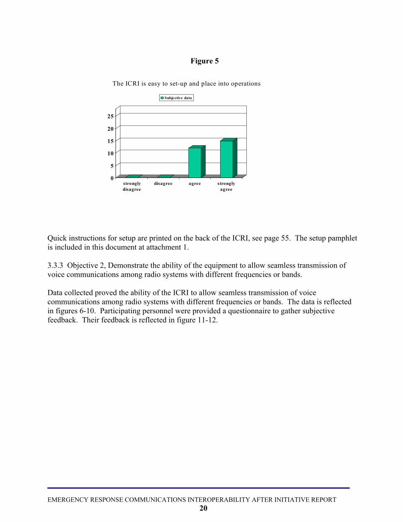
t the system could be setup and operational within 10 minutes by s of training. Data showed this in all 6 timed tests. Participating questionnaire to gather subjective feedback. Their feedback is
OMMUNICATIONS INTEROPERABILITY AFTER INITIATIVE REPORT 19
0
5
10
15
20
25
stronglydisagree
disagree agree stronglyagree
Subjective data
The ICRI is easy to set-up and place into operations
Figure 5
Quick instructions for setup are printed on the back of the ICRI, see page 55. The setup pamphlet is included in this document at attachment 1. 3.3.3 Objective 2, Demonstrate the ability of the equipment to allow seamless transmission of voice communications among radio systems with different frequencies or bands. Data collected proved the ability of the ICRI to allow seamless transmission of voice communications among radio systems with different frequencies or bands. The data is reflected in figures 6-10. Participating personnel were provided a questionnaire to gather subjective feedback. Their feedback is reflected in figure 11-12.
EMERGENCY RESPONSE COMMUNICATIONS INTEROPERABILITY AFTER INITIATIVE REPORT
20

Figure 6
Item 1- Mwithin a m Item 2- Mwithin a m Item 3- Mwithin a m Item 4- Nphone to aNokia 613 Patrolmenwas also twords or s
EMERGEN
otorola MT-100, 150 MHZ, on channel 1. An identical radio on channel 1 was placed ile radius and operated by a patrolman.
otorola Saber 1, 150 MHZ, on channel 2. An identical radio on channel 2 was placed ile radius and operated by a patrolman.
otorola Saber 1, 150 MHZ, on channel 3. An identical radio on channel 3 was placed ile radius and operated by a patrolman.
okia cellular phone model 3585i (Sprint PCS service). A call was placed from this Nokia cellular phone model 6134 (Cingular service). A patrolman was operating the 4 phone within a mile radius.
(item 1-4) were able to transmit and receive all communications from each other. This rue for the handset. The results of all tests were loud, clear and with no clipping of yllables.
Abilene Police Department, TX
CY RESPONSE COMMUNICATIONS INTEROPERABILITY AFTER INITIATIVE REPORT 21

Figure 7
Item 1- Motorola Astro Saber, 150 MHZ, on channel 1. An identical radio on channel 1 was placed within a three-mile radius and operated by Dyess AFB Fire Dept personnel. Item 2- Motorola Astro Saber, 150 MHZ, on channel 2. An identical radio on channel 2 was placed within a three-mile radius and operated by 7th Security Forces personnel. Item 3- Motorola XTS-3000, 150 MHZ, on channel 3. An identical radio on channel 3 was placed within a three-mile radius and operated by the 7th Mission Support Group Commander. Personnel (item 1-3) were able to transmit and receive all communications from each other. The results of all tests were loud, clear and with no clipping of words or syllables.
Dyess Air Force Base, TX
EMERGENCY RESPONSE COMMUNICATIONS INTEROPERABILITY AFTER INITIATIVE REPORT
22

Figure 8
Item 1- Kenwood 481, 900 MHZ, on channel 1. An identical radio on channel 1 was used to talk around by American Medical Response personnel. Item 2- Motorola XTS-3000, 400 MHZ, on channel 2. An identical radio on channel 2 was used to talk around by Peterson AFB, Fire Dept. Item 3- Motorola XTS-3000, 800 MHZ, on channel 2. An identical radio on channel 2 was used to talk around by Colorado Springss Office of Emergency Management. Personnel (item 1-3) were able to transmit and receive all communications from each other. The results of all tests were loud, clear and with no clipping of words or syllables.
Colorado Springs Airport, CO
EMERGENCY RESPONSE COMMUNICATIONS INTEROPERABILITY AFTER INITIATIVE REPORT
23

Figure 9
Item 1- Kenwood TK 290, 150 MHZ, on channel 1. Piercpersonnel used an identical radio on channel 1 for talk arou Item 2- MPA Ericsson PAJ02, 150 MHZ, on channel 2. PManagement personnel used an identical radio on channel 2 Item 3- Motorola XTS-5000, 400 MHZ, on channel 1. Thpersonnel used an identical radio on channel 1 for talk arou Item 4- Motorola Astro Saber, 400 MHZ, on channel 1. Tused an identical radio on channel 1 for talk around. Personnel (item 1-4) were able to transmit and receive all cresults of all tests were loud, clear and with no clipping of w
EMERGENCY RESPONSE COMMUNICATIONS INTEROPERABI
24
McChord AFB, WA
e Country Emergency Management nd.
ierce Country Emergency for talk around.
e 62nd Communication Squadron nd.
he 62nd Security Forces personnel
ommunications from each other. The ords or syllables.
LITY AFTER INITIATIVE REPORT

Figure 10
Item 1- Motorola HT 750, 400 MHZ, on channel 1. Lakewradio on channel 1 for talk around. Item 2- Motorola Astro Saber, 400 MHZ, on channel 1. Thused an identical radio on channel 1 for talk around. Item 3- Motorola XTS-5000, 400 MHZ, on channel 1. Thepersonnel used an identical radio on channel 1 for talk aroun Item 4- Com-Net Ericsson MPA, 150 MHZ, on channel 2. Management personnel used an identical radio on channel 2 Item 5- EF Johnson, 150 MHZ, on channel 1. City of Tacoon channel 1 for talk around. This was the only test with mixed results. It could not be deradio systems plugged into the ICRI, the ICRI itself, a defecItem 1 and item 2 could transmit and receive to/from each otscratchy though somewhat understandable. Item 1, 2, and 3 transmissions from item 2 and 3 but item 1 could not transmto all, but receptions from all were scratchy but understandabtested. All items could transmit and receive but item 2 recepunderstandable. Item 2 was switched out at the ICRI with anstill not understandable.
EMERGENCY RESPONSE COMMUNICATIONS INTEROPERABIL
25
McChord AFB, WA
ood Fire Dept used an identical
e Fort Lewis Fire Dept personnel
62nd Communication Squadron d.
Pierce Country Emergency for talk around
ma personnel used an identical radio
termined if the problem was due to tive cable or a combination of issues. her but reception on item 2 was very were tested and item 1 received it. Item 2 and 3 were able to transmit le. Item 1-5 were all connected and tion was scratchy and not other radio but results were similar,
ITY AFTER INITIATIVE REPORT

0
5
10
15
20
25
stronglydisagree
disagree agree stronglyagree
Subjective data
The ICRI established an effective means for immediate command and control with multiple agencies operating on dissimilar radios.
Figure 11
EMERGENCY RESPONSE COMMUNICATIONS INTEROPERABILITY AFTER INITIATIVE REPORT
26

0
5
10
15
20
25
stronglydisagree
disagree agree stronglyagree
Subjective data
The ICRI allowed effective communications between multiple agencies to be understandable and with little or no interference.
Figure 12
3.3.4. Objective 3, Demonstrate the ability of a radio interoperability capability to allow communications between first responders in large buildings and their control centers. Data collected proved the ability of a radio interoperability capability to enhance communications between first responders in large buildings and their control centers outside. The data is reflected in figures 13-15.
EMERGENCY RESPONSE COMMUNICATIONS INTEROPERABILITY AFTER INITIATIVE REPORT
27

Figure 13
Item 1- Motorola XTS 3000, 800 MHZ, on channel 1(simplex). Arlington Fire Dept used an identical radio on channel 1 and walked the inside of the Pentagon basement to fifth floor in corridor 7 and 8. Item 2- Motorola XTS 3000, 800 MHZ, on channel 2 (trunked)). Base station located at the Arlington Fire Dept. Before the test started, an attempt to communicate with each other (on trunked channel 2) inside the Pentagon meet with very negative results. In fact, personnel were able to talk to each other better by yelling down the corridor than using the trunked system channel. A test of the fire dept simplex channel showed they could communicate with each other effectively inside the Pentagon on all floors except the fifth. The ICRI was setup about 20 feet from the entrance to corridor 7 and 8. The ICRI effectively relayed transmissions to and from item1 and item 2. The results of all tests were loud, clear and with no clipping of words or syllables.
Pentagon Corridor 7 and 8
EMERGENCY RESPONSE COMMUNICATIONS INTEROPERABILITY AFTER INITIATIVE REPORT
28

Figure 14
Item 1- Motorola XTS 3000, 400 MHZ, on channel 1. Pentagon Force Protection Agency used an identical radio on channel 1 and walked both level 1 and 2 of the metro. Item 2- Motorola XTS 3000, 400 MHZ, on channel 2. Pentagon Force Protection Agency used an identical radio on channel 2 and located the radio near the south Pentagon parking lot. Before the test started an attempt to communicate between item 1 and item 2 was negative. The ICRI was setup at the bottom of the escalator. The ICRI effectively relayed transmissions to and from item1 and item 2. The results of all tests were loud, clear and with no clipping of words or syllables.
Pentagon Metro Station
EMERGENCY RESPONSE COMMUNICATIONS INTEROPERABILITY AFTER INITIATIVE REPORT
29

Figure 15
Item 1- Motorola Astro Saber, 400 MHZ, on channel 1(simplex). Lackland AFB Fire Dept used an identical radio on channel 1 and walk the inside of Wilford Hall Medical Center (WHMC) basement to seventh floor. Item 2- Motorola XTS 3000, 400 MHZ, on channel 2 (trunked)). Base station located on Lackland, approx 2 miles away. Before the test started, an attempt to communicate with each other (on trunked channel 2) inside WHMC meet with very negative results. A test of the fire dept simplex channel showed they could communicate with each other effectively inside WHMC. The ICRI was setup about 10 feet from the entrance to WHMC. The ICRI effectively relayed transmissions to and from item1 and item 2. The results of all tests were loud, clear and with no clipping of words or syllables.
Wilford Hall Medical Center
EMERGENCY RESPONSE COMMUNICATIONS INTEROPERABILITY AFTER INITIATIVE REPORT
30

4.1 GENERAL This proof of concept demonstrinteroperability capability. Thetransmissions of voice communor bands. 4.2 SPECIFIC DEFICIEN During testing at Dyess AFB, T#179.0710) was defective. Theit wasn’t keyed. C-AT was resp 4.3 SPECIFIC RECOMM The Emergency Response Coma radio interoperability capabilipiece of equipment that allows first responders. Recommend aPolice Standards and Procedure
EMERGENCY RESPONSE COMM
4. RECOMMENDATIONS
ation was successful in illustrating the utility of a radio results clearly shows the ICRI is capable of allowing seamless ications among agencies operating on different radio frequencies
CIES
X, an interface connection cable for an Astro Saber (C-AT part cable caused continuous transmission from the radio even when onsive and offered to replace the cable via overnight shipping.
ENDATIONS
munications Interoperability initiative demonstrated the utility of ty through the use of the ICRI. The ICRI is an effective, low cost a rapid communication link up between military, state and local requirement for the equipment be placed in AFI 31-201, Security s, under paragraph 4.5.
UNICATIONS INTEROPERABILITY AFTER INITIATIVE REPORT 31

DESCRIPTION 1. ICRI with attachments 2. ICRI system used for testing 3. ICRI in Pelican carry case 4. 10-port ICRI system, not teste 5. Subjective data on ICRI setup 6. ICRI test, Abilene TX 7. ICRI test, Dyess AFB, TX 8. ICRI test, Colorado Springs A 9. ICRI test, McChord AFB, WA 10. ICRI test, McChord AFB, W 11. Subjective data on ICRI com 12. Subjective data on ICRI trans 13. ICRI test, Pentagon, corridor 14. ICRI test, Pentagon, Metro S 15. ICRI test, Wilford Hall Medi
EMERGENCY RESPONSE COMMUN
LIST OF FIGURES
PAGE
9
10
10
d 10
19
20
21
irport, CO 22
23
A (second test) 24
mand and control effectiveness 25
missions understandability 26
7 and 8 28
tation 29
cal Center, Lackland AFB, TX 30
ICATIONS INTEROPERABILITY AFTER INITIATIVE REPORT 32

1. ICRI Setup and operating pro 2. Evaluation of the Incident Co
rescue teams, conducted by FRescue.
EMERGENCY RESPONSE COMMUNIC
ATTACHMENT
cedures
mmander’s Radio Interface for use by urban search and airfax Country Fire and Rescue and Urban Search and
ATIONS INTEROPERABILITY AFTER INITIATIVE REPORT 33

ATTACHMENT 1
Setup and Operating Procedures
ICRITM
Incident Commanders’ Radio Interface TM
A Rapidly Deployable, Radio Interoperability Solution For
Emergency Responders
EMERGENCY RESPONSE COMMUNICATIONS INTEROPERABILITY AFTER INITIATIVE REPORT
34

TABLE OF CONTENTS: THEORY OF OPERATION ..................................................................................................... 36
PRE-OPERATIONAL ACTIVITIES....................................................................................... 37
1.0 SET-UP AND USE INSTRUCTIONS ............................................................................ 38 FIGURE 1: ICRI CASE (OUTSIDE) ........................................................................................... 38 FIGURE 2: ICRI CASE (INSIDE) ............................................................................................... 38 FIGURE 3: PLACEMENT INSIDE CASE.................................................................................. 39 FIGURE 4: ICRI WITH OPTIONAL HANDSET....................................................................... 39
2.0 ICRI POWER.................................................................................................................... 40 FIGURE 5: BATTERY INSTALLATION (DRAWING) ........................................................... 40 FIGURE 6: BATTERY CASE ..................................................................................................... 40 FIGURE 7: BATTERY CASE (INTERIOR) ............................................................................... 41 FIGURE 9: BATTERY ATTATCHMENT TO ICRI (VIEW 2) ................................................. 42 FIGURE 10: DC POWER SUPPLY SUBASSEMBLIES ........................................................... 42 FIGURE 11: IN-LINE PLUG ASSEMBLY................................................................................. 43 FIGURE 12: ICRI WITH EXTERNAL POWER SUPPLY......................................................... 43
3.0 LAND MOBILE RADIO INTERFACE......................................................................... 44
FIGURE 13: RADIO WITH ICRI CABLE ATTATCHED......................................................... 44 FIGURE 14: ICRI INTERFACE JACKS AND TALK GROUP SELECTOR............................ 44 FIGURE 15: TWO RADIOS CONNECTED TO ICRI .............................................................. 45 FIGURE 16: JACK ASSEMBLY (DRAWING).......................................................................... 45
4.0 TELEPHONE AND CELLULAR PHONE INTERFACE........................................... 46 FIGURE 17: ACOUSTIC COUPLER.......................................................................................... 46 FIGURE 18: ACOUSTIC COUPLER TO CELLULAR PHONE ............................................... 46 FIGURE 20: TELEPHONE INTERFACE JACK........................................................................ 47 FIGURE 21: TELELPHONE CONNECTOR ASSEMBLY (DRAWING)................................. 48 FIGURE 22: CELLULAR PHONE CONNECTOR (VIEW 1) ................................................... 49 FIGURE 23: CELLULAR PHONE CONNECTOR (VIEW 2) ................................................... 49
5.0 LINKING ICRIS............................................................................................................... 50 FIGURE 26: INTERFACE CONNECTOR ASSEMBLE (DRAWING)..................................... 50
APPENDIX A: PART NUMBERS FOR ICRI, ACCESSORIES AND RADIO CABLES . 54
APPENDIX C: CONNECTOR PIN-OUT DATA ................................................................... 56
APPENDIX D: PICTORIALS OF APPLICATIONS............................................................. 57
APPENDIX E: PICTORIALS OF BOARD ADJUSTMENTS .............................................. 59
EMERGENCY RESPONSE COMMUNICATIONS INTEROPERABILITY AFTER INITIATIVE REPORT
35

Theory of Operation The ICRI is a quick setup device that can provide two, three, four, five or six public safety agencies with radio interoperability as a tactical situation is rapidly unfolding before them. The ICRI requires little manpower resource to move it into place, to enable it initially, or to maintain its operation over many hours. The ICRI was designed to provide full operational capabilities in as little as one minute after arrival on-scene and the ICRI can remain operational for 24 hours on 8 “AA” batteries. Multiple ICRI-based “nets” can be operated a single incident; multiple ICRI-based “nets” can be rapidly linked together without hand tool and/or adjustments. In simplest terms, the ICRI performs two primary functions: • Distributes audio received from one two-way radio to other radios, telephone or
recording device connected to the ICRI. • Utilizes this same incoming audio to “key” the other radios connected to the
ICRI. The ICRI does not discriminate or evaluate the incoming audio so that delays are not inserted into the audio transfer or “keying” processes. Radios, telephones and/or recording devices connected to the ICRI are provided with the incoming essentially in real-time (an initial delay at keying to preserve the first syllables of incoming audio as the transmitters [including wide area, repeater-based “trunked” radio systems] are keyed up). An ICRI contains up to six circuits that key the radios connected to the ICRI; these circuits are commonly referred to as “VOX” or “voice-activated switches.” The ICRI uses these circuits to perform other controlling functions as well. Only the VOX directly connected to the incoming audio is used to key each of the other radios simultaneously (all other are temporarily disabled, preventing a second “voice” from causing a disruption in initial voice being distributed).
EMERGENCY RESPONSE COMMUNICATIONS INTEROPERABILITY AFTER INITIATIVE REPORT
36

Pre-Operational Activities Some pre-planning is necessary to ready the ICRI for use. The following should be accounted for before placing the ICRI on-line: 1.0 Predetermine what the power source will be for the ICRI and verify that the
cable or battery pack is available. 2.0 Predetermine what brand and model of radios will be connected to the ICRI
and that an “interconnect” cable for each radio is available. 3.0 Advise agencies that they will need to supply a “spare” radio, for the radio
interoperability, that the radio supplied must be known to operate properly and have at least one fully charged battery.
The ICRI can be powered by a 9-volt DC battery or any DC source up to 20 VDC. The LEDs on the ICRI provide information battery status, in particular, a reliable indication of a low voltage condition. Note that if eight “AA batteries are used, the ICRI will continue operate to nominally for at lea t 2 hours after the “OK” LED is extinguished and the “LOW” LED has lit and then extinguished (batteries will provide a reduced duty cycle due to low quality, poor storage conditions before use, and/or low temperature during use).
s
Among the possible power sources that can be used to power the ICRI are: • 12 or 24 volt vehicle battery • Vehicle cigarette lighter • 115VAC (with an external adapter) • BA590 “military” • CommICRIal dry-cell battery (12V or greater) • C-AT 12 volt battery pack (uses 8 “AA” batteries) The ICRI’s internal regulated power supply is both reverse polarity protected, but it is important to check polarity of DC supplies before connecting them to the ICRI. Note that the ICRI power input connector information appears on the bottom of the ICRI.
EMERGENCY RESPONSE COMMUNICATIONS INTEROPERABILITY AFTER INITIATIVE REPORT
37
1.0 Set-up and Use Instructions
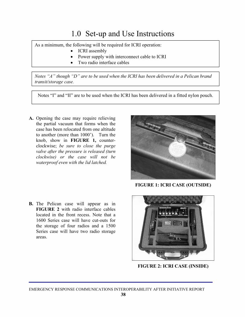
Notes “I” and “II” are to be used when the ICRI has been delivered in a fitted nylon pouch.
Notes “A” though “D” are to be used when the ICRI has been delivered in a Pelican brand transit/storage case.
As a minimum, the following will be required for ICRI operation: • ICRI assembly • Power supply with interconnect cable to ICRI • Two radio interface cables
A. Opening the case may require relieving
the partial vacuum that forms when the case has been relocated from one altitude to another (more than 1000’). Turn the knob, show in FIGURE 1, counter-clockwise; be sure to close the purge valve after the pressure is released (turn clockwise) or the case will not be waterproof even with the lid latched.
FIGURE 1: ICRI CASE (OUTSIDE)
B. The Pelican case will appear as in FIGURE 2 with radio interface cables located in the front recess. Note that a 1600 Series case will have cut-outs for the storage of four radios and a 1500 Series case will have two radio storage areas.
FIGURE 2: ICRI CASE (INSIDE)
EMERGENCY RESPONSE COMMUNICATIONS INTEROPERABILITY AFTER INITIATIVE REPORT
38

C. Additional cutouts are provided for the
storage of an extra battery pack (a), and for the positioning of radios (b) during ICRI operations.
FIGURE 3: PLACEMENT INSIDE CASE
I. A storage compartment for cables and batteries is located at the rear of the pouch. (The internal strap prevents the ICRI from falling through the open zippered compartment. FIGURE 5.)
FIGURE 4: ICRI WITH OPTIONAL HANDSET
II. Abbreviated set-up instructions are printed onto the top cover of the ICRI assembly. Connector information for radio, telephone, and power interconnect cables is printed on the bottom of the ICRI assembly. Refer to Appendices B and C.
EMERGENCY RESPONSE COMMUNICATIONS INTEROPERABILITY AFTER INITIATIVE REPORT
39

2.0 ICRI POWER 2.1. To power the ICRI with the C-AT battery pack (8 “AA” cells), use the following
instructions. FIGURE 5, FIGURE 6, FIGURE 7, FIGURE 8 and FIGURE 9.
N
EME
The battery housing is comprised of two parts; the exterior case and an internal tray. O TOOLS ARE NEEDED TO REMOVE THE TRAY AND REPLACE THE BATTERIES
FIGURE 5: BATTERY INSTALLATION (DRAWING)
FIGURE 6: BATTERY CASE
RGENCY RESPONSE COMMUNICATIONS INTEROPERABILITY AFTER INITIATIVE REPORT 40

2.1.1. Hold the battery housing securely in the palm of the hand with metal battery terminal plate facing up. Push firmly on the center of the battery terminal plate, until the battery tray is released.
2.1.2. Remove old batteries and discard properly.
2.1.3. Replace the 8 "AA” alkaline batteries, observing polarity markings within the tray.
Note: There is a “key” tab on the side of the tray and a “keyway” inside of case. 2.1.4. To reinsert the tray, make sure the
tray’s key goes in the matching slot side of the case, FIGURE 5. Insert the tray into the housing from the bottom end of the case, pushing the tray until it “locks” into place. FIGURE 7.
2.1.5. To reinstall the assembled battery pack onto the adapter, align the slots on the top of the battery pack with the slide rails on the adapter. Slide the battery pack onto the adaptor until it “locks” in place and the edges of the battery pack are aligned with the edges of the adaptor. FIGURE 6.
FIGURE 7: BATTERY CASE (INTERIOR)
FIGURE 8: BATTERY ATTATCHMENT TO ICRI (VIEW 1)
EMERGENCY RESPONSE COMMUNICATIONS INTEROPERABILITY AFTER INITIATIVE REPORT 41

EMERGENCY RESPONSE COMMUNICATIONS INTEROPERABILITY AFTER INITIATIVE REPORT 42
FIGURE 9: BATTERY ATTATCHMENT TO ICRI (VIEW 2)
2.2. To use an alternate DC source to power the ICRI, use the following instructions.
2.2.1. When powering the ICRI with an alternate DC source or through a vehicle cigarette lighter jack, the cable assembly consists of three subassemblies: (A) the universal interconnect cable, (B) the cigarette lighter plug/ locking in-line jack and (C) the alligator clips/locking in-line jack. FIGURE 10 and FIGURE 11.
2.2.2. After selecting the DC source connect the in-line jack to the in-line plug. Note that the pins are polarized and the connection is made so that the jack’s locking “blades” slide between the “blades” on the plug and the body of the plug.
2.2.3. Connect the assembled cable to the external DC source.
2.2.4. Connect the adapter’s plug to the jack labeled DC INPUT.
Note: Align the plug’s “key” with the jack’s “keyway” before attempting to insert the plug. 2.2.5. To remove the plug, hold the fluted part of the plug’s barrel and pull straight out.
2.2.6. To separate the in-line socket, gently lift one of the blades from the plug so that the locking mechanism is released. Then pull the plug and socket apart.
FIGURE 10: DC POWER SUPPLY SUBASSEMBLIES

FIGURE 11: IN-LINE PLUG ASSEMBLY
2.3. Use the following instructions to power the ICRI through AC.
2.3.1. This power supply consists of two parts: (A) the three-prong AC power cable and (B) an AC to DC converter with an interconnect cable, FIGURE 12.
Note: The AC supply must not be used where the cables or converter can become wet.
2.3.2. Connect the power cord to the converter and to the DC source (110-120V, 60Hz).
2.3.3. Connect the adapter’s plug to the jack labeled DC INPUT.
Note: Align the plug’s “key” with the jack’s “keyway” before attempting to insert the plug.
2.3.4. To remove the plug, hold the fluted part of the plug’s barrel and pull straight out.
FIGURE 12: ICRI WITH EXTERNAL POWER SUPPLY
EMERGENCY RESPONSE COMMUNICATIONS INTEROPERABILITY AFTER INITIATIVE REPORT 43

3.0 Land Mobile Radio Interface
NOTE: Radio interconnect cables are generally specific to a radio brand and model, although some manufacturer’s use the same connector for several radio models. Interconnect cables provided by C-AT have a seven digit part number label on the cable. A chart crossing these numbers with the radio brands/models appear in Appendix A of this document.
3.1. Install the radio-end of the ICRI interconnect cable onto the radio, as you would install any radio accessory (i.e.: a shoulder speaker / microphone).
3.1.1. Tightening any locking screws is optional; but it is important that the connector be firmly seated against the radio so that good electrical contact is made. FIGURE 13.
3.1.2. Attach the other end of the cable to any of the LAND MOBILE RADIO INTERFACE jacks, labeled 1, 2, 3, 4 and 5. FIGURE 14 and FIGURE 15.
NOTE: The plug on the cable and the jack are “keyed”. Be sure to align the key before inserting the plug on to the connector or the connection may be damaged.
FIGURE 13: RADIO WITH ICRI
CABLE ATTATCHED
FIGURE 14: ICRI INTERFACE JACKS AND TALK GROUP SELECTOR
EMERGENCY RESPONSE COMMUNICATIONS INTEROPERABILITY AFTER INITIATIVE REPORT
44

EMERGENCY RESPONSE COMMUNICATIONS INTEROPERABILITY AFTER INITIATIVE REPORT 45
FIGURE 15: TWO RADIOS CONNECTED TO ICRI3.1.3. After the plug is fully seated on the jack, the locking ring on the plug should be turned
clockwise until the ring cannot be turned further. FIGURE 16.
FIGURE 16: JACK ASSEMBLY (DRAWING)
3.1.4. To remove the connector for cable storage, push inward on the locking ring and turn the ring counter clockwise to release the locking mechanism. Then pull the connector straight out of the jack. Hold the chrome barrel of the connector rather than the cable.

4.0 TELEPHONE AND CELLULAR PHONE INTERFACE
NOTE: If a land-line or cellular telephone will be linked through the ICRI to the 2-way radios, the “acoustic coupler” interconnect cable (part number 179.0650) can be used.
If a cellular telephone with a 2.5mm “headset” jack will be linked through the ICRI to the 2-way radios, an interconnect cable (part number 179.0672) with a 2.5mm plug can be used.
FIGURE 17: ACOUSTIC COUPLER 4.1. The acoustic coupler, FIGURE 17, is installed on a telephone handset or cellular telephone by positioning the transducers over the speaker and microphone of the telephone.
4.2. FIGURE 18 and
4.3. FIGURE 19.
4.3.1. Position the BLACK pad directly over the speaker (labeled TO EARPIECE on its cable) and secure by stretching the elastic strap over the handset/cell phone.
4.3.2. Position the RED pad directly over the microphone (labeled TO MOUTH-PIECE on its cable) and secure by stretching the elastic strap over the handset/cell phone. Based on the design of the cellular telephone, to place an out-going call may require moving the transducers in order to access the cell phone’s keypad. FIGURE 18: ACOUSTIC COUPLER TO
CELLULAR PHONE
EMERGENCY RESPONSE COMMUNICATIONS INTEROPERABILITY AFTER INITIATIVE REPORT 46

FIGURE 19: ACOUSTIC COUPLER TO CORDED PHONE
4.3.3. Plug into ICRI at jack labeled “Telephone Interface (Coupler)”, FIGURE 20.
NOTE: The plug on the cable and the jack are “keyed”. Be sure to align the key before inserting the plug on to the connector or the connection may be damaged.
4.3.4. After the plug is fully seated on the jack, the locking ring on the plug should be turned clockwise until the ring cannot be turned further. FIGURE 21.
4.3.5. Set telephone’s earphone audio to a mid-level setting following the telephone’s instructions.
4.3.6. After the interconnect cable from the repeater is connected to the telephone handset, a dial tone should be heard in the earphones of the portable radio and in the earpiece of the "local" handset.
4.3.7. Dial the telephone number of another telephone.
FIGURE 20: TELEPHONE
INTERFACE JACK 4.3.8. When the called party answers, use
the portable radio's throat mic or a headset and begin to converse with called party.
4.3.9. To remove the connector for cable storage, push inward on the locking ring and turn the ring counter clockwise to release the locking mechanism. Then pull the connector straight out of the jack. Hold the chrome barrel of the connector rather than the cable.
EMERGENCY RESPONSE COMMUNICATIONS INTEROPERABILITY AFTER INITIATIVE REPORT 47

FIGURE 21: TELELPHONE CONNECTOR ASSEMBLY (DRAWING)
EMERGENCY RESPONSE COMMUNICATIONS INTEROPERABILITY AFTER INITIATIVE REPORT 48

4.2 When connecting to a cellular telephone connect the small, single shaft connector to the headset jack on the cellular telephone. Be sure it is firmly seated in the telephone. FIGURE 22 and FIGURE 23. Plug into ICRI at jack labeled “Telephone Interface (Coupler)”, FIGURE 20.
4.2.1. When connecting to a cellular
telephone connect the small, single shaft connector to the headset jack on the cellular telephone. Be sure it is firmly seated in the telephone. FIGURE 22 and FIGURE 23. Plug into ICRI at jack labeled “Telephone Interface (Coupler)”, FIGURE 20.
NOTE: The plug on the cable and the jack are “keyed”. Be sure to align the key before inserting the plug on to the connector or the connection may be damaged. 4.2.2. After the plug is fully seated on the
jack, the locking ring on the plug should be turned clockwise until the ring cannot be turned further. FIGURE 21.
4.2.3. Set telephone’s earphone audio to a
mid-level setting following the telephone’s instructions.
4.2.4. After the interconnect cable from the
repeater is connected to the telephone handset, a dial tone should be heard in the earphones of the portable radio and in the earpiece of the "local" handset.
4.2.5. Dial the telephone number of another
telephone. 4.2.6. When the called party answers, use
the portable radio's throat mic or a headset and begin to converse with called party.
4.2.7. To remove the connector for cable
storage, push inward on the locking ring and turn the ring counter clockwise to release the locking mechanism. Then pull the connector straight out of the jack. Hold the chrome barrel of the connector rather than the cable.
FIGURE 22: CELLULAR PHONE CONNECTOR (VIEW 1)
FIGURE 23: CELLULAR PHONE CONNECTOR (VIEW 2)
EMERGENCY RESPONSE COMMUNICATIONS INTEROPERABILITY AFTER INITIATIVE REPORT 49

5.0 LINKING ICRIs
FIGURE 24: TWO LINKED ICRIs
FIGURE 25: INTERFACE JACK
5.1. Connecting an interface cable, PN 179.0656, to the Telephone Interface jacks of two ICRIs will permit interoperability of more than five radios,
5.2. FIGURE 24. 5.2.1. Plug into ICRI at jack labeled
“Telephone.”
5.2.2. FIGURE 25.
NOTE: The plug on the cable and the jack are “keyed”. Be sure to align the key before inserting the plug on to the connector or the connection may be damaged.
5.2.3. After the plug is fully seated on the jack, the locking ring on the plug should be turned clockwise until the ring cannot be turned further. FIGURE 26.
5.2.4. To remove the connector for cable storage, push inward on the locking ring and turn the ring counter clockwise to release the locking mechanism. Then pull the connector straight out of the jack. Hold the chrome barrel of the connector rather than the cable.
FIGURE 26: INTERFACE CONNECTOR ASSEMBLE (DRAWING)
EMERGENCY RESPONSE COMMUNICATIONS INTEROPERABILITY AFTER INITIATIVE REPORT 50

EMERGENCY RESPONSE COMMUNICATIONS INTEROPERABILITY AFTER INITIATIVE REPORT 51
5.3. Setup:
5.3.1. After connecting a power source to the ICRI (A), turn on the ICRI at (B) so that power up and input voltage can be verified. If you need to use a DC source voltage between 6.5 and 7.4 volts, then neither the OK (C) nor the LOW (D) voltage LEDs will be lit, but the ICRI will be working.
5.3.2. Connect the radio interface cables to the ICRI. All five ICRI radio interface connections (E1-5) are electrically identical, so it is not important which jacks are used during ICRI operation.
5.3.3. Connect the radio interface cables to the radios.
5.3.4. Be sure the radios are on the channels assigned to the interoperability function.
5.3.5. Select the talk-group the radio will be assigned to and place the switch above the associated post in the designated position.
NOTE: The center position of the switch places any item connected with the associated port into a “NO CONNECTION” conduction without physically disconnecting the device from the ICRI.
5.3.6. Turn the radios on; initially place the radio volume controls at a mid-position between fully counter-clockwise and fully clockwise. As a radio connected to the ICRI receives voice for a remote radio user for the first time, adjust the radio’s volume control so that the associated LED flickers as words are spoken. The LED should not remain on continuously as the voice is received.
5.3.7. Connect the telephone and handset, if they will be used.
5.3.8. Select the talk-group the telephone and/or handset will be associated with.
5.3.9. Turn on the telephone.
EMERGENCY RESPONSE COMMUNICATIONS INTEROPERABILITY AFTER INITIATIVE REPORT 52
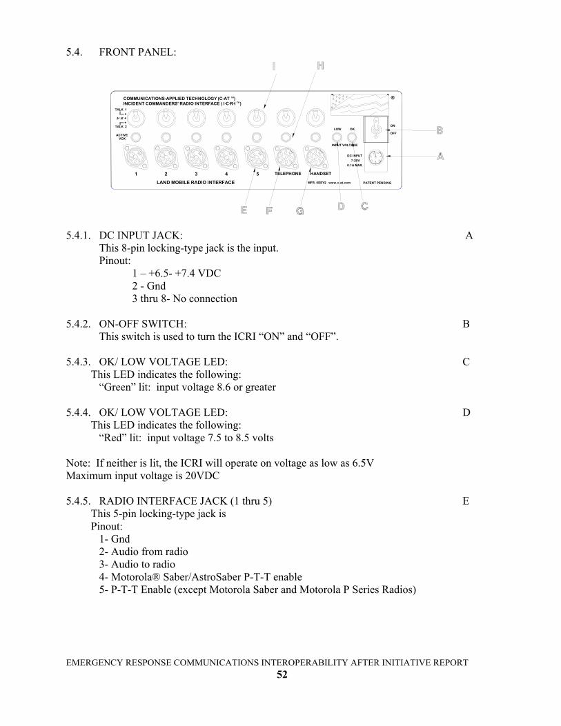
5.4. FRONT PANEL:
MFR. 0EEY2 www.c-at.com
HANDSET
LAND MOBILE RADIO INTERFACE
1 32 54 TELEPHONE
INCIDENT COMMANDERS' RADIO INTERFACE ( I C R I )COMMUNICATIONS-APPLIED TECHNOLOGY (C-AT )
ACTIVEVOX
TALK 2
TALK 1
1 2
TM
TM
PATENT PENDING
0.1A MAX.
DC INPUT7-20V
R
INPUT VOLTAGE
LOW OKOFF
ON
5.4.1. DC INPUT JACK: A
This 8-pin locking-type jack is the input. Pinout:
1 – +6.5- +7.4 VDC 2 - Gnd 3 thru 8- No connection
5.4.2. ON-OFF SWITCH: B
This switch is used to turn the ICRI “ON” and “OFF”. 5.4.3. OK/ LOW VOLTAGE LED: C This LED indicates the following: “Green” lit: input voltage 8.6 or greater 5.4.4. OK/ LOW VOLTAGE LED: D This LED indicates the following: “Red” lit: input voltage 7.5 to 8.5 volts Note: If neither is lit, the ICRI will operate on voltage as low as 6.5V Maximum input voltage is 20VDC 5.4.5. RADIO INTERFACE JACK (1 thru 5) E This 5-pin locking-type jack is Pinout: 1- Gnd 2- Audio from radio 3- Audio to radio 4- Motorola® Saber/AstroSaber P-T-T enable 5- P-T-T Enable (except Motorola Saber and Motorola P Series Radios)

5.4.6. TELEPHONE INTERFACE JACK: F
This 8-pin locking-type jack supports the connection of the ICRI to a telephone through the acoustic coupler (PN 1790650) or the 2.5mm jack on a cell phone (PN 179.0672)
Pinout: 1- Audio TO telephone (acoustic coupler) 2- Audio FROM telephone (acoustic coupler) 3- Audio TO telephone (acoustic coupler) 4- Audio FROM telephone (acoustic coupler) 5- Ground 6- Required jumper 7- Audio TO telephone (2.5mm plug) 8- Audio FROM telephone (2.5mm plug) 5.4.7. HANDSET INTERFACE JACK G
This 5 pin 240 degree connector supports the handset (p/n 179.0676) Pinout: 1- Ground 2- Electret Mic 3- PTT 4- Audio Hi+ 5- Audio Hi- 5.4.8. VOICE ACTIVATED CIRCUIT (VOX) LED INDICATOR: H
When lit (only one at a time) indicates the VOX, of the “inputting” radio is active.
5.4.9. TALK GROUP SWITCH: I UP: Talk Group 1 CENTER: Not connected to either talk group
DOWN: Talk Group 2
EMERGENCY RESPONSE COMMUNICATIONS INTEROPERABILITY AFTER INITIATIVE REPORT 53

EMERGENCY RESPONSE COMMUNICATIONS INTEROPERABILITY AFTER INITIATIVE REPORT 54
APPENDIX A: Part Numbers for ICRI, Accessories and Radio Cables
ICRI WORKSHEET Part Number ICRI, 5 radio I/O ports and 1 telephone I/O port, with padded carrying case 500.9250 ICRI, 5 radio + 1 handset + 1 telephone I/O port, supplied with padded carrying case. TWO TALK GROUP SELECTION for PORTS
500.9260 POWER OPTIONS ICRI to 8 “AA” battery pack adaptor cable 180.0450 8 “AA” battery pack 160.3611 DC input cable, dual mode (alligator clips and vehicle cigarette lighter plug) 179.0730 115V AC adaptor (in-line switching power supply) 320.0431 TRANSIT/STORAGE CASES OPTIONS Waterproof case (Pelican 1550) with fitted foam insert 990.9602 Waterproof case (Pelican 1600) with fitted foam insert 990.0601 RADIO INTERFACE CABLES (RF ISOLATED VERSIONS) Kenwood TM 280/290/380/390/480/481 radio interface cable 179.0136 Bendix King TM LPH radio interface cable 179.0671 Bendix KingTM EPH interface cable 179.0673 Com-Net EricssonTM Jaguar radio interface cable/amplifier 179.0733 Com-Net EricssonTM LPE 200 radio interface cable/amplifier 179.0662 Com-Net EricssonTM MPA radio interface cable/amplifier 179.0660 Com-Net EricssonTM MRK radio interface cable/amplifier 179.0661 Com-Net EricssonTM Panther 500 & KPC interface cable 179.0732 Com-Net EricssonTM Panther 600 interface cable 180.0738 MotorolaTM models MT-2000, JT-1000, HT-1000, MTS-2000, MTX-6000, MTX-838 & XTS-3000 interface cable 179.0630 MotorolaTM models GTX, LTS2000, GP300, P1225 interface cable 179.0634 MotorolaTM models HT750, HT1250 interface cable 179.0735 MotorolaTM models Astro/Saber, Saber I, II, and III interface cable 179.0710 MotorolaTM models MT-1000, HT-600, HT-2000, MT-300, MTX-800, MTX-820S, MTX-900 & Radius P-200 interface cable 179.0640 MotorolaTM Spectra interface cable ("Y" cable/box so normal function of radio is not affected by ICRI link) 179.0636 MotorolaTM MCS-2000 interface cable ("Y" cable/box so normal function of radio is not affected by ICRI link) 179.0635 MotorolaTM Maxtrac interface cable ("Y" cable/box so normal function of radio is not affected by ICRI link) 179.0639 NextelTM cell phone/radio interface cable for radio mode 179.0677 SINCGARS, PRC-117, and other “green gear” radio interface cable (U-229/U connector: 5-pin) or (U-329/U: 6- pin) 179.0600 PRC-127 radio interface cable 179.0740 ICRI-to-ICRI link cable to expand # of linked radios (note: requires use of both telephone interface ports) 179.0656 Radio adaptor cable with 6 or 12 pin HiroseTM termination 179.1910 Handset with noise-canceling microphone, P-T-T bar, and coiled cord 280.0125 Universal radio interface cable (requires radio speaker/mic assembly to be provided for disassembly) 179.0734 TELEPHONE OPTIONS Cellular telephone (generic, acoustic coupler) interface cable 179.0655 Direct connection cable to cellular telephone headset jack (2.5mm plug) 179.0672 Direct connection cable to modular telephone handset jack 179.0676 Analog telephone interface (RJ-11) with DTMF pad and handset 500.9290 OTHER OPTIONS 250’ universal extension cable on cable reel with radio “holder” (used in conjunction with any radio interface cable) 179.6206 Audio buffer delay for individual radio port (C-AT will contact you for port/delay period) 500.9310 Audio buffer delay for all radio ports (C-AT will contact you for delay period) 500.9311 NOTE: Please contact C-AT if you require an interface cable for a radio not listed

EMERGENCY RESPONSE COMMUNICATIONS INTEROPERABILITY AFTER INITIATIVE REPORT 55
APPENDIX B: ICRI Chassis: Set-up Instructions
THEY SHOULD NOT BE SET ON TOP OF ONE ANOTHER.
"TO MOUTHPIECE"
NOTE: CONNECTOR PIN-OUT INFORMATION IS LOCATED ON THEBOTTOM OF THE CHASSIS OF THE ICRI.
STAYS ON CONTINUOUSLY, OR SO LOW THAT IT MISSES SYALLABLES.
9. IF THE TELEPHONE INTERFACE IS USED, THE ATTACHMENT OF THE ACOUSTIC COUPLER
CHANNEL "LED" FLASHES IN RESPONSE TO THE VOICE. DO NOT ADJUST SO HIGH THAT IT8. WHILE RECEIVING A SIGNAL, ADJUST THE RADIO VOLUME CONTROL SO THAT THE
"TO EARPIECE"
ATTACH CABLE MARKED
TO ICRI
SHOULD BE MADE ACCORDING TO THE FOLLOWING DIAGRAM:
ATTACH CABLE MARKED
FINE TUNING:
OPERATE THE ICRI, BUT IF THE SOURCE IS "AA" BATTERIES THEN THEY SHOULD BE
THE 3-POSITION SWITCHES THAT ARE LOCATED ABOVE EACH PORT.SELECT TALK GROUP ASSIGNMENT FOR EACH CONNECTED DEVICE UTILIZING
4. CONNECT THE RADIO, TELEPHONE INTERFACE CABLES TO THE ICRI; CONNECTWHEN THE CONNECTORS ARE SEATED ON THE JACKS,
NOTE: TO REMOVE THE CONNECTOR, TURN THE "RING" COUNTER-CLOCKWISE TO UNLOCK THE CONNECTOR, AND THEN PULL ON THE CONNECTOR BODY INSTEAD OF TWISTING OR
5. BEFORE CONNECTING A RADIO, LANDLINE TELEPHONE OR CELLULAR TELEPHONE TO THEICRI VERIFY THAT IT IS WORKING NORMALLY AND HAS A FULLY CHARGED BATTERY. THEN
7. TURN ON THE RADIO(S) AND PLACE THE RADIO VOLUME CONTROL(S) IN A MID POSITION
NOTE: THE RADIOS DO NOT HAVE TO BE SEPARATED BY ANY PARTICULAR DISTANCE, BUT
6a. FOR ICRIs EQUIPPED WITH TALK GROUP SELECTION:
TURN OFF THE RADIO OR TELEPHONE.
6. CONNECT THE RADIO INTERFACE CABLE(S) TO THE RADIO(S).
OF THE KNOB'S ROTATION.
CHANGED TO FRESH ONES AT THE EARLIEST OPPORTUNITY.
TURN THE "RING" CLOCKWISE TO LOCK THE CONNECTOR IN-PLACE.
TURNING THE CONNECTOR.
THE HANDSET TO THE ICRI.
SET-UP INSTRUCTIONS FOR THE ICRI
BATTERY PACK, THE 115V AC CONVERTER, OR THE CIGARETTE LIGHTER ADAPTOR. THE
NOTE: TO REMOVE THE CONNECTOR, PULL ON THE BACK OF THE CONNECTOR BODY
AT BOTH ENDS. THE RED LIGHT INDICATES THAT THE SOURCE VOLTAGE IS ENOUGH TO
1. SELECT THE POWER SOURCE TO BE USED: 12 V "AA" ALKALINE BATTERY PACK, 115V AC,
2. CONNECT THE EXTERNAL POWER SUPPLY TO THE ICRI USING EITHER THE "AA" ALKALINE
CONNECTOR IS "KEYED"; DO NOT ATTEMPT TO FORCE THE CONNECTOR INTO THE JACK
3. TURN ON THE ICRI. THE RED OR GREEN LIGHT BELOW THE POWER SWITCH SHOULD BE LIT.
NOTE: IF NEITHER LIGHT IS LIT, VERIFY THAT THE POWER SOURCE IS PROPERLY CONNECTED
INSTEAD OF TWISTING OR TURNING THE CONNECTOR.
ON THE ICRI.
(SEE MANUAL FOR GREATER DETAILS)
OR VEHICLE SUPPLIED DC.
TM
CAN BE FOUND ON THE TOP COVER OF THE ICRI

EMERGENCY RESPONSE COMMUNICATIONS INTEROPERABILITY AFTER INITIATIVE REPORT 56
APPENDIX C: Connector Pin-out Data
3-PTT
2- ELECTRET MIC
4-AUDIO HI+
1- GND
SWITCHCRAFT # 12CL5MHANDSET INTERFACE
5-AUDIO HI-
4 23
5 1
240° SWITCHCRAFT # 15CL8M
4
ALL CONNECTOR INFORMATION VIEWED FROM THIS POINT (WIRED SIDE).
CELL PHONE
2-AUDIO FROM RADIO4- SABER P-T-T ONLY
3-AUDIO TO RADIO5-P-T-T
SWITCHCRAFT # 05CL5MRADIO INTERFACE
53
180°
1- GND42
1
5 1
5-SHIELD GND
4 -FROM PHONE
2 4
2 -FROM PHONE
83
25
ACOUSTIC COUPLER
3 -TO PHONE
1 -TO PHONE
SWITCHCRAFT # 15CL8M
8
73 6
INTERFACE
7
TO ICRI
NEUTRIX #SC8 -QTY 1
NEUTRIX #FI8 -QTY 1
2-GND(-)1-POWER(+)
NEUTRIX #BS1 -QTY 2
3-8 - N/C
NEUTRIX #SR8 -QTY 1
6 6-REQUIRED JUMPER
5-SHIELD GND
1
3 4
1
2 8
7 6
5
7-TO PHONE8-FROM PHONE
INTERFACE
POWER CONNECTOR
BOTTOM OF ICRI CHASSIS

EMERGENCY RESPONSE COMMUNICATIONS INTEROPERABILITY AFTER INITIATIVE REPORT 57
APPENDIX D: Pictorials of Applications
TAPE RECORDER
MOBILE VEHICLE-MOUNT RADIO
RECEIVERBODY WIRE
CHANNEL LINKTALK AROUND
LINK TO TRUNKED REPEATER
INTERFACE
UP TO 1,000'
TRUNKED CHANNEL
REPEATER
REPEATING BODY WIRE SIGNAL
CABLE
1st RESPONDER
BELOW GRADE OR IN-BUILDING
ICRI ALTERNATE APPLICATIONS

EMERGENCY RESPONSE COMMUNICATIONS INTEROPERABILITY AFTER INITIATIVE REPORT 58
ALLIGATOR CLIPS
INTERCONNECT CABLE TECHNICAL NOTES ON BOTTOM SIDE.(PORTABLE OR MOBILE RADIO CAN BE USED.)
USER INSTRUCTIONS ON TOP COVER.2
1PORTS ARE NOT RADIO SPECIFIC
11
1
3
INTERFACE CABLE
3
1
UP TO 1,000'
CIGARETTE LIGHTER
8 "AA" BATTERY PACK
1
OR
OR
(+) RED
(-) BLACK
ICRI WITH ATTACHMENTS
2
OR
(NOTE: NOT TO SCALE)

APPENDIX E: Pictorials of Board Adjustments
EMERGENCY RESPONSE COMMUNICATIONS INTEROPERABILITY AFTER INITIATIVE REPORT
59
R2543
LOC
ATIO
N O
F AD
JUSTM
ENTS
WI TH
JUM
PER O
N, SH
OR
T BLO
CK
ING
0.8 SEC(STA
ND
AR
D)
FUN
CT IO
N O
F JUM
PERS J19 T0 J23
WITH
OU
T J UM
PER, LO
NG
BLO
CK
I NG
- 2 SEC
CH
AN
NEL
R27
21
R43
R60
R222
R211
R15 9
R243
R206
R334
NO
TE: TC1-TC
6 AR
E TEST CO
NN
ECTIO
NS . D
O N
OT I N
STALL JU
MPER
S.
R350
TOT A
DJ
HA
ND
SET4
5
R77
R94
P HO
NE
R126
AC
OU
TO
UT
R135
WIR
ED
R106
AC
IN
SENS.
R12 9
INW
IRED
R339
TAIL
R188IN
R303
R27 5
R238
R286
R307
R270
R318

EMERGENCY RESPONSE COMMUNICATIONS INTEROPERABILITY AFTER INITIATIVE REPORT
extend batt ery life. Note than the pro gram
ming ju m
pers on JP1 8 must also b e set to the
approximat ely 30 second s to 2 m
inut es, as set by t ime out tim
er adjust contro ls. If the
TIME O
UT TIM
ER D
E FEAT: W
ith this jumper " off", the tele phone or radi o input chann el w
ill be
stan dard configu ration. With the jum
per re moved, this t im
e is extend ed to approx imately
INP U
T BLO
CK
I NG
TIME JU
MPER
S: With jum
pers " on", the ICR
I will respond to a new
voi ce signal
AU
DIO
BU
FFER D
E LAY
CIR
CU
IT POW
ER C
ON
TRO
L: If the audio delay will no t be used, JP1 6 can be rem
oved to
HA
ND
SET CIR
CU
IT POW
E R C
ON
TRO
L : If the hand set circuit will not be use d, JP5 can be rem
oved
ope ration return s to normal. Installation o f defeat jum
p er turns off t he time out ti m
er and
NO
NE
NO
NE
JUM
P ER PIN
S
9-10200
approx imately 0.8 s econds after the last transm
ission has e nded. This is the
i nput signal is removed for approxim
ate ly 5 seconds, the time out tim
er resets a nd
t emporarily d isabled after a tim
ed perio d of continuo us activity. T he timing ra nge is
2 seco nds. During this tim
e, no new PTT can be initiated b y any input except the
b ypass for the unit to work properly w
it h the delay d isabled.
to turn off power to the circuit an d extend bat tery life.
NO
TES FOR
I CR
I GEN
3 CO
NFIG
UR
ATIO
N D
RA
WIN
G:
the ch annel will ne ver be disabl ed.
handset.
100150
11-12
TAL K
GR
OU
P 1(D
ELAY
1)
(DE LA
Y 2)
TALK
GR
OU
P 2
CH
AN
NEL
ICR
I GE N
3 DELA
Y
SELECT JU
MPER
S(D
ELAY
AM
OU
NT)
JP17 6511 9 7
1012 8
3 14 2
1-2,
5 00
350
25 0
300
40 0
1 00
20 0150
300
250
350
9 -10,
11-12
11-129 -10,
7-8
7-8,9-107- 8,
11- 12
5- 6
7-8,
5-63-4
1-2
3-4,
5-6
DELA
Y(m
SEC)
500
400
1-2,
3-41-2,5-63-4,
ICR
I GEN
3 AU
DIO
BU
FFER D
ELAY
S ELEC
T JUM
PERS
(AC
TIVA
T E/BY
PASS)
JP 18
21 4365 87
TALK
GR
OU
P 2
T ALK
GR
OU
P 1
CH
AN
NEL
BY
PAS S
DELA
Y
BY
PASS
3-7
7-83-4,
1-5
JUM
PER PIN
S
DEL A
Y
MO
DE
5-61-2,
60

ATTACHMENT 2
National Technology Transfer Center Emergency Response Technology Program
Test and Evaluation Report Evaluation of the Incident Commanders’ Radio
Interface For use by USAR Teams
Conducted by
Fairfax County Fire & Rescue Urban Search & Rescue
June 17, 2003
This report is an accurate assessment of the performance of the ICRI as described. It does not imply a "product
endorsement" by Fairfax County Fire and Rescue, the National Technology Transfer Center, or the Department of Homeland Security.
EMERGENCY RESPONSE COMMUNICATIONS INTEROPERABILITY AFTER INITIATIVE REPORT
61

Evaluation of the Incident Commanders’ Radio Interface Fairfax County Fire & Rescue Urban Search & Rescue
June 17, 2003
On June 10, 2003 the Fairfax County Fire & Rescue Urban Search & Rescue (VATF-1) received an Incident Commanders’ Radio Interface (ICRI) from Communications-Applied Technology, located in Reston Virginia, to evaluate. The ICRI is an audio switch that uses operator supplied portable or mobile radio to provide interfaces between incompatible radio systems. The ICRI also can be used as a radio interconnect to phone systems. The ICRI uses supplied adaptor cables to attach different devices to the audio switch. The ICRI came equipped as follows:
1 ICRI Dual talk, S/N 3024 1 250 foot cable spool 1 Battery Adapter 1 Battery Pack 1 Pelican Case 3 Motorola STX Adaptor Cables 1 Motorola HT-600 Adaptor Cable 1 Handset 1 Manual 1 Telephone Adaptor Cable 1 Nextel model 90 Adaptor Cable
Three of the VATF-1 Communications Team members conducted the evaluation. They were as follows: Frank Stoda Communications Team Manager Rick Schmidt Communications Specialist John Rogers Communications Specialist Executive Summary The Incident Commanders’ Radio Interface (ICRI) from Communications-Applied Technology was found to be a useful communications tool for the taskforce. The ICRI is light, small, and easily packed in the cache. Its phone patch capability could provide first responders with direct communications to resources that would be available only by phone to radio relay. This could prove valuable in the WMD environment. It also allows connection to other agencies or operations with very little setup time or communications knowledge. All tests, on usable radio/phone systems, with the ICRI provided good reliable communications. We conducted several test of audio quality, ease of setup, and usability of the ICRI.
EMERGENCY RESPONSE COMMUNICATIONS INTEROPERABILITY AFTER INITIATIVE REPORT
62

The first test was to simulate patching two Motorola Astro Digital Trunked Radio Systems together. To do this we used four STX 3000 800 MHz portable radios. Radio 1 was used by team A for communications on fire channel 4G. Radio 2 was used by team B for communications on fire channel 4H. Radio 3 was attached to port 1 of the ICRI with a Motorola STX adaptor cable and set to monitor fire channel 4G. Radio 3 was attached to port 3 of the ICRI with a Motorola STX adaptor cable and set to monitor fire channel 4H. Team A conducted a test count on (using Radio 1) on fire channel 4G. The portable radio transmission was picked up and transported through the trunked radio system on channel 4G. The signal repeated through the trunked radio system was in turn was picked up by Radio 3. The ICRI patched the signal from Radio 3 to Radio 4. Radio 4 then transmitted the test count on fire channel 4H. This transmission was picked up and transported through the trunked radio system on channel 4H. The signal repeated through the trunked radio system was in turn was picked up by Radio 2 and Team B monitored the test count. The test was then done in reverse and Team B gave a test count that was monitored by team A. Results: The test count in both directions was clear and complete. There was no induced distortion or clipping of words or syllables by the VOX patching done by the ICRI. The second test conducted was to simulate cross patching of simplex radios. To do this we used two Motorola MT 1000 UHF and two Motorola HT 600 VHF radios. Team A used a MT 1000 UHF radio and the second MT 1000 was attached to port 2 of the ICRI with a Motorola STX adaptor cable. Team B used a HT 600 radio and the second HT 600 radio was attached to port 4 of the ICRI with the HT 600 interface cable. The MT 1000 portables were set to channel 15 a talkaround channel with GSTAR signaling on key up. The MT 600 radio were set to FMARS 3 a simplex radio channel. When team A keyed up the radio, the radios attached to the ICRI started a series of rapid key ups. It was found that the GSTAR signal burst was causing this for some reason (we did not do an in-depth investigation of the problem). We than changed the channel on the MT 1000 to channel 11, a simplex that does not have GSTAR. Results: All cross band communications worked properly. All communications were clear and complete with no clipping of words or syllables. The third test was the simulation of a simplex channel to a digital trunked radio system. To do this we used two Motorola STX 3000 800 MHZ radios and two Motorola MT 1000 UHF radios. Team A used a MT 1000 UHF radio and the second MT 1000 was attached to port 2 of the ICRI with a Motorola STX adaptor cable. Team B used a Motorola STX 3000 800 MHZ radio and the second Motorola STX 3000 800 MHZ radio was attached to port 1 of the ICRI. The MT 1000 radios were set to simplex channel 11. The STX 3000 800 MHZ radios were set to talk group 4H. Test counts were conducted from team A to team B and from team B to team A. Results:
EMERGENCY RESPONSE COMMUNICATIONS INTEROPERABILITY AFTER INITIATIVE REPORT
63

All communications were clear and complete with no clipping of words or syllables. Test four was to simulate a telephone interconnect to a simplex radio. To do this we used two standard landline phones and two HT 1000 UHF radios. Team A used a MT 1000 UHF radio and the second MT 1000 was attached to port 2 of the ICRI with a Motorola STX adaptor cable. Team B used a landline phone to call the second landline phone connected to the ICRI box at port 6 by the phone adaptor cable. The communications from team A to team B were loud, clear, and complete with no clipping of words or syllables. The communications from team B (phone) were somewhat low in level and the VOX had a tendency to clip the audio. Although provisions and instructions on level setting were provided, we elected to talk loudly on the phone in lieu of making level adjustments in the ICRI. When team B talked loudly into the phone communications from team B to team Results: A was loud, clear, and complete with no clipping of words or syllables. Test five was to simulate a telephone interconnect to a digital trunked radio. To do this we used two standard landline phones and two STX 3000 800 MHz radios. Team A used a STX 3000 800 MHz radio and the second STX 3000 800 MHz radio was attached to port 2 of the ICRI with a Motorola STX adaptor cable. Team B used a landline phone to call the second landline phone connected to the ICRI box at port 6 by the phone adaptor cable. Results: The communications from team A to team B were loud, clear, and complete with no clipping of words or syllables. When team B talked loudly into the phone communications from team B to team A were loud, clear, and complete with no clipping of words or syllables. Test six was to simulate a cell phone interconnect to a simplex radio. To do this we used a Nokia cell phone (with Cingular service), a standard landline phone, and two MT 1000 UHF radios. Team A used a MT 1000 UHF radio and the second MT 1000 was attached to port 2 of the ICRI with a Motorola STX adaptor cable. Team B used a landline phone to call the Nokia Cell phone connected to the ICRI box at port 6 by the phone adaptor cable. Results: The communications from team A to team B were loud, clear, and complete with no clipping of words or syllables. When team B talked loudly into the phone communications from team B to team A were loud, clear, and complete with no clipping of words or syllables. Test seven was to simulate a cell phone interconnect to a digital trunked radio. To do this we used a Nokia cell phone (with Cingular service), a standard landline phone, and two STX 3000 800 MHz radios. Team A used a STX 3000 800 MHz radio and the second STX 3000 800 MHz radio was attached to port 2 of the ICRI with a Motorola STX adaptor cable. Team B used a landline phone to call the Nokia Cell phone connected to the ICRI box at port 6 by the phone adaptor cable.
EMERGENCY RESPONSE COMMUNICATIONS INTEROPERABILITY AFTER INITIATIVE REPORT
64

EMERGENCY RESPONSE COMMUNICATIONS INTEROPERABILITY AFTER INITIATIVE REPORT
65
Results: The communications from team A to team B were loud, clear, and complete with no clipping of words or syllables. When team B talked loudly into the phone communications from team B to team A were loud, clear, and complete with no clipping of words or syllables. Several tests were conducted using a NEXTEL phone with direct connect. Tests were conducted using the standard telephone adaptor cable and the NEXTEL model 90 adaptor cable. Results: Because the tests were conducted in an area that has marginal NEXTEL coverage none of the tests were successful. POC for this report Dewey Perks Task Force Leader USAID SAR Team 1, Virginia Task Force 1 Fairfax County Fire and Rescue Fairfax, VA 22030 Tel 703-815-5523