woodward.suwoodward.su/files/1878260071-26284_d.pdf · definitions this is the safety alert symbol....
TRANSCRIPT

Installation and Operation Manual
GTC100 Gas Turbine Control for Generator or Compressor Applications
8262-1001—with PowerSense (for Power Gen) 8262-1003—typically for Compressor Drive
Manual 26284 (Revision D)
DEFINITIONS
This is the safety alert symbol. It is used to alert you to potential personal injury hazards. Obey all safety messages that follow this symbol to avoid possible injury or death.
• DANGER—Indicates a hazardous situation which, if not avoided, will result in death or serious injury.
• WARNING—Indicates a hazardous situation which, if not avoided, could result in death or serious injury.
• CAUTION—Indicates a hazardous situation which, if not avoided, could result in minor or moderate injury.
• NOTICE—Indicates a hazard that could result in property damage only (including damage to the control).
• IMPORTANT—Designates an operating tip or maintenance suggestion.
The engine, turbine, or other type of prime mover should be equipped with an overspeed shutdown device to protect against runaway or damage to the prime mover with possible personal injury, loss of life, or property damage.
The overspeed shutdown device must be totally independent of the prime mover control system. An overtemperature or overpressure shutdown device may also be needed for safety, as appropriate.
Read this entire manual and all other publications pertaining to the work to be performed before installing, operating, or servicing this equipment. Practice all plant and safety instructions and precautions. Failure to follow instructions can cause personal injury and/or property damage.
This publication may have been revised or updated since this copy was produced. To verify that you have the latest revision, be sure to check the Woodward website:
www.woodward.com/pubs/current.pdf The revision level is shown at the bottom of the front cover after the publication number. The latest version of most publications is available at:
www.woodward.com/publications If your publication is not there, please contact your customer service representative to get the latest copy.
Any unauthorized modifications to or use of this equipment outside its specified mechanical, electrical, or other operating limits may cause personal injury and/or property damage, including damage to the equipment. Any such unauthorized modifications: (i) constitute "misuse" and/or "negligence" within the meaning of the product warranty thereby excluding warranty coverage for any resulting damage, and (ii) invalidate product certifications or listings.
To prevent damage to a control system that uses an alternator or battery-charging device, make sure the charging device is turned off before disconnecting the battery from the system.
To prevent damage to electronic components caused by improper handling, read and observe the precautions in Woodward manual 82715, Guide for Handling and Protection of Electronic Controls, Printed Circuit Boards, and Modules.
Revisions—Text changes are indicated by a black line alongside the text. Woodward Governor Company reserves the right to update any portion of this publication at any time. Information provided by Woodward Governor Company is believed to be correct and reliable. However, no responsibility is assumed by Woodward Governor Company unless otherwise expressly undertaken.
© Woodward 2005 All Rights Reserved
Manual 26284 GTC100 Gas Turbine Control
Woodward i
Contents
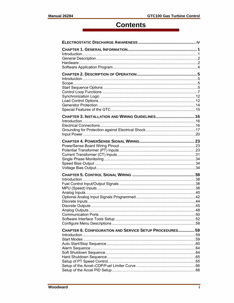
ELECTROSTATIC DISCHARGE AWARENESS ................................................. IV CHAPTER 1. GENERAL INFORMATION ........................................................... 1 Introduction ............................................................................................................. 1 General Description ................................................................................................ 2 Hardware ................................................................................................................ 2 Software Application Program ................................................................................ 4
CHAPTER 2. DESCRIPTION OF OPERATION ................................................... 5 Introduction ............................................................................................................. 5 Scope ...................................................................................................................... 5 Start Sequence Options ......................................................................................... 5 Control Loop Functions .......................................................................................... 7 Synchronization Logic .......................................................................................... 12 Load Control Options ............................................................................................ 12 Generator Protection ............................................................................................ 14 Special Features of the GTC ................................................................................ 15
CHAPTER 3. INSTALLATION AND WIRING GUIDELINES ................................. 16 Introduction ........................................................................................................... 16 Electrical Connections .......................................................................................... 16 Grounding for Protection against Electrical Shock ............................................... 17 Input Power .......................................................................................................... 20
CHAPTER 4. POWERSENSE SIGNAL WIRING ............................................... 23 PowerSense Board Wiring Pinout ........................................................................ 23 Potential Transformer (PT) Inputs ........................................................................ 23 Current Transformer (CT) Inputs .......................................................................... 31 Single Phase Monitoring ....................................................................................... 34 Speed Bias Output ............................................................................................... 34 Voltage Bias Output .............................................................................................. 34
CHAPTER 5. CONTROL SIGNAL WIRING ..................................................... 38 Introduction ........................................................................................................... 38 Fuel Control Input/Output Signals ........................................................................ 38 MPU (Speed) Inputs ............................................................................................. 38 Analog Inputs ........................................................................................................ 40 Optional Analog Input Signals Programmed ........................................................ 42 Discrete Inputs ...................................................................................................... 44 Discrete Outputs ................................................................................................... 45 Analog Outputs ..................................................................................................... 48 Communication Ports ........................................................................................... 50 Software Interface Tools Setup ............................................................................ 52 Configure Menu Descriptions ............................................................................... 58
CHAPTER 6. CONFIGURATION AND SERVICE SETUP PROCEDURES .............. 59 Introduction ........................................................................................................... 59 Start Modes .......................................................................................................... 59 Auto Start/Stop Sequence .................................................................................... 60 Alarm Sequence ................................................................................................... 64 Soft Shutdown Sequence ..................................................................................... 64 Hard Shutdown Sequence.................................................................................... 65 Setup of PT Speed Control................................................................................... 65 Setup of the Accel–CDP/Fuel Limiter Curve ........................................................ 66 Setup of the Accel PID Setup ............................................................................... 66
GTC100 Gas Turbine Control Manual 26284
ii Woodward
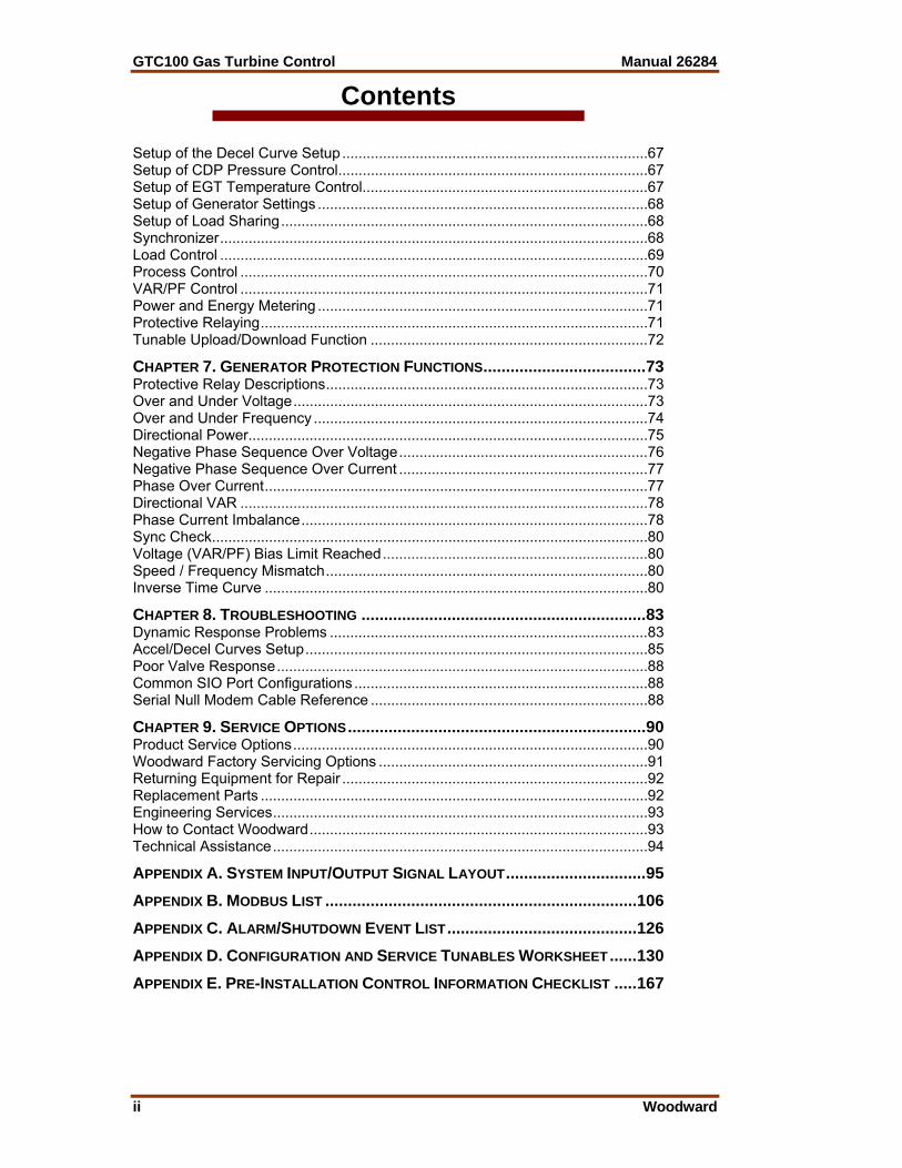
Contents Setup of the Decel Curve Setup ........................................................................... 67 Setup of CDP Pressure Control ............................................................................ 67 Setup of EGT Temperature Control...................................................................... 67 Setup of Generator Settings ................................................................................. 68 Setup of Load Sharing .......................................................................................... 68 Synchronizer ......................................................................................................... 68 Load Control ......................................................................................................... 69 Process Control .................................................................................................... 70 VAR/PF Control .................................................................................................... 71 Power and Energy Metering ................................................................................. 71 Protective Relaying ............................................................................................... 71 Tunable Upload/Download Function .................................................................... 72
CHAPTER 7. GENERATOR PROTECTION FUNCTIONS .................................... 73 Protective Relay Descriptions ............................................................................... 73 Over and Under Voltage ....................................................................................... 73 Over and Under Frequency .................................................................................. 74 Directional Power.................................................................................................. 75 Negative Phase Sequence Over Voltage ............................................................. 76 Negative Phase Sequence Over Current ............................................................. 77 Phase Over Current .............................................................................................. 77 Directional VAR .................................................................................................... 78 Phase Current Imbalance ..................................................................................... 78 Sync Check ........................................................................................................... 80 Voltage (VAR/PF) Bias Limit Reached ................................................................. 80 Speed / Frequency Mismatch ............................................................................... 80 Inverse Time Curve .............................................................................................. 80
CHAPTER 8. TROUBLESHOOTING ............................................................... 83 Dynamic Response Problems .............................................................................. 83 Accel/Decel Curves Setup .................................................................................... 85 Poor Valve Response ........................................................................................... 88 Common SIO Port Configurations ........................................................................ 88 Serial Null Modem Cable Reference .................................................................... 88
CHAPTER 9. SERVICE OPTIONS .................................................................. 90 Product Service Options ....................................................................................... 90 Woodward Factory Servicing Options .................................................................. 91 Returning Equipment for Repair ........................................................................... 92 Replacement Parts ............................................................................................... 92 Engineering Services ............................................................................................ 93 How to Contact Woodward ................................................................................... 93 Technical Assistance ............................................................................................ 94
APPENDIX A. SYSTEM INPUT/OUTPUT SIGNAL LAYOUT ............................... 95 APPENDIX B. MODBUS LIST ..................................................................... 106 APPENDIX C. ALARM/SHUTDOWN EVENT LIST .......................................... 126 APPENDIX D. CONFIGURATION AND SERVICE TUNABLES WORKSHEET ...... 130 APPENDIX E. PRE-INSTALLATION CONTROL INFORMATION CHECKLIST ..... 167
Manual 26284 GTC100 Gas Turbine Control
Woodward iii
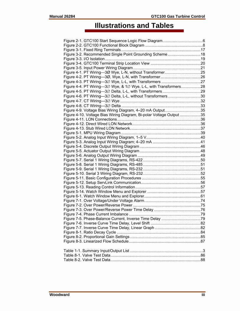
Illustrations and Tables Figure 2-1. GTC100 Start Sequence Logic Flow Diagram ..................................... 6 Figure 2-2. GTC100 Functional Block Diagram ..................................................... 8 Figure 3-1. Fixed Ring Terminals ......................................................................... 17 Figure 3-2. Recommended Single Point Grounding Scheme .............................. 18 Figure 3-3. I/O Isolation ........................................................................................ 19 Figure 3-4. GTC100 Terminal Strip Location View .............................................. 20 Figure 3-5. Input Power Wiring Diagram .............................................................. 21 Figure 4-1. PT Wiring—3Ø Wye, L-N, without Transformer ................................. 25 Figure 4-2. PT Wiring—3Ø, Wye, L-N, with Transformer ..................................... 26 Figure 4-3. PT Wiring—3∅ Wye, L-L, with Transformers .................................... 27 Figure 4-4. PT Wiring—3∅ Wye, & 1∅ Wye, L-L, with Transformers .................. 28 Figure 4-5. PT Wiring—3∅ Delta, L-L, with Transformers ................................... 29 Figure 4-6. PT Wiring—3∅ Delta, L-L, without Transformers .............................. 30 Figure 4-7. CT Wiring—3∅ Wye .......................................................................... 32 Figure 4-8. CT Wiring—3∅ Delta ......................................................................... 33 Figure 4-9. Voltage Bias Wiring Diagram, 4–20 mA Output ................................. 35 Figure 4-10. Voltage Bias Wiring Diagram, Bi-polar Voltage Output ................... 35 Figure 4-11. LON Connections ............................................................................. 36 Figure 4-12. Direct Wired LON Network ............................................................... 36 Figure 4-13. Stub Wired LON Network ................................................................. 37 Figure 5-1. MPU Wiring Diagram ......................................................................... 39 Figure 5-2. Analog Input Wiring Diagram, 1–5 V.................................................. 40 Figure 5-3. Analog Input Wiring Diagram; 4–20 mA ............................................ 41 Figure 5-4. Discrete Output Wiring Diagram ........................................................ 46 Figure 5-5. Actuator Output Wiring Diagram ........................................................ 48 Figure 5-6. Analog Output Wiring Diagram .......................................................... 49 Figure 5-7. Serial 1 Wiring Diagrams, RS-422 ..................................................... 50 Figure 5-8. Serial 1 Wiring Diagrams, RS-485 ..................................................... 51 Figure 5-9. Serial 1 Wiring Diagrams, RS-232 ..................................................... 51 Figure 5-10. Serial 3 Wiring Diagram, RS-232 ..................................................... 52 Figure 5-11. Basic Configuration Procedures ...................................................... 55 Figure 5-12. Setup ServLink Communication ....................................................... 56 Figure 5-13. Reading Control Information ............................................................ 57 Figure 5-14. Watch Window Menu and Explorer ................................................. 57 Figure 6-1. Watch Window Menu and Explorer .................................................... 61 Figure 7-1. Over Voltage/Under Voltage Alarm.................................................... 74 Figure 7-2. Over Power/Reverse Power .............................................................. 75 Figure 7-3. Over Power/Reverse Power Time Delay ........................................... 76 Figure 7-4. Phase Current Imbalance .................................................................. 79 Figure 7-5. Phase-Balance Current, Inverse Time Delay .................................... 79 Figure 7-6. Inverse Curve Time Delay, Level Shift .............................................. 82 Figure 7-7. Inverse Curve Time Delay, Linear Graph .......................................... 82 Figure 8-1. Ratio Decay Cycle ............................................................................. 84 Figure 8-2. Proportional Gain Settings ................................................................. 85 Figure 8-3. Linearized Flow Schedule .................................................................. 87 Table 1-1. Summary Input/Output List ................................................................... 3 Table 8-1. Valve Test Data ................................................................................... 86 Table 8-2. Valve Test Data ................................................................................... 88

GTC100 Gas Turbine Control Manual 26284
iv Woodward
Electrostatic Discharge Awareness All electronic equipment is static-sensitive, some components more than others. To protect these components from static damage, you must take special precautions to minimize or eliminate electrostatic discharges. Follow these precautions when working with or near the control. 1. Before doing maintenance on the electronic control, discharge the static
electricity on your body to ground by touching and holding a grounded metal object (pipes, cabinets, equipment, etc.).
2. Avoid the build-up of static electricity on your body by not wearing clothing
made of synthetic materials. Wear cotton or cotton-blend materials as much as possible because these do not store static electric charges as much as synthetics.
3. Keep plastic, vinyl, and Styrofoam materials (such as plastic or Styrofoam
cups, cup holders, cigarette packages, cellophane wrappers, vinyl books or folders, plastic bottles, and plastic ash trays) away from the control, the modules, and the work area as much as possible.
4. Do not remove the printed circuit board (PCB) from the control cabinet
unless absolutely necessary. If you must remove the PCB from the control cabinet, follow these precautions:
• Do not touch any part of the PCB except the edges. • Do not touch the electrical conductors, the connectors, or the
components with conductive devices or with your hands. • When replacing a PCB, keep the new PCB in the plastic antistatic
protective bag it comes in until you are ready to install it. Immediately after removing the old PCB from the control cabinet, place it in the antistatic protective bag.
To prevent damage to electronic components caused by improper handling, read and observe the precautions in Woodward manual 82715, Guide for Handling and Protection of Electronic Controls, Printed Circuit Boards, and Modules.
Manual 26284 GTC100 Gas Turbine Control
Woodward 1
Chapter 1. General Information
Introduction This manual describes the GTC100 Digital Control System designed to control single-shaft gas turbines for compressor or generator applications. It is pre-programmed to perform fuel metering control, start/stop sequencing and communications to a package OI (Operator Interface) or plant DCS (Distributed Control System). There are two models, one with a PowerSense module and one without that module. This manual should be used along with the standard AtlasSC™ hardware manual (26179), and therefore the scope of this document is only to describe details of the GTC100 application software functionality and assist the customer in configuration and start-up of the control. Refer to manual 26179 for information on hardware specifications, mounting information, and wiring details. • The GTC100 performs the functions described above. It is intended for
applications on turbine compressor packages, but can also be applied on power generation packages.
• The GTC100 with PowerSense includes a module in the control package that will enable the GTC to receive generator and bus signals so that the control can add synchronization, load sharing and power metering functions to the features of the base GTC100 listed above. For isolated bus operation the control will operate in isochronous, and can close the generator to a dead bus. It is intended for use on systems where generator sets operate in parallel on a common bus and may be tied to the utility mains.
Scope of Supply Item # Description 8262-1001 GTC100—AtlasSC w/ PSENS (Single Shaft Gas Turbine Fuel
Control) 8262-1003 GTC100—AtlasSC (Single Shaft Gas Turbine Fuel Control) BCD85213 CD—GTC100 System Documentation & Software Tools Optional Add-ons Item # Description [Inquire] Operator Interface 1784-505 Moore Industries AD590 Ambient Temperature Signal Converter 8900-067 Ambient Air Temperature Sensor (AD590) 5441-699 Relay Interface (12) FTM 5417-747 Relay FTM Interface Cable 8200-224 Servo Position Controller (SPC)

GTC100 Gas Turbine Control Manual 26284
2 Woodward
General Description The Woodward GTC100 AtlasSC Digital Control System is a configurable control system for gas turbines that produces a fuel demand output to control speed, load, pressure, and temperature. It contains optional start/stop sequence control and Modbus® * communication links to an optional HMI or a user defined operator interface. In addition to this, the control allows the packager or user to utilize pre-programmed options by the way in which they configure the unit. The model with PowerSense includes an I/O module that interfaces to Generator and Utility bus PT’s and CT’s allowing this version to include synchronization, power metering, breaker commands and load sharing to the base offering of the GTC100. For a given GTC model, the maximum I/O available is fixed and has been pre-programmed into the unit. If additional I/O is required, the customer should inquire about other models of the GTC family.
*—Modbus is a trademark of Schneider Automation Inc.
Hardware The GTC100 AtlasSC Digital Control is designed to be bulkhead mounted in a control panel. The complete unit contains a ‘SmartCore’ CPU module, a Power Supply board, and may contain the optional PowerSense module. In addition, the system can also include an optional relay Field Termination Module (FTM). These components are designed for DIN rail mounting in the control cabinet. The CPU module controls the system. The I/O modules interface the CPU module to the outside world, permitting it to sense digital and analog inputs and to issue analog and discrete outputs. Optional relays are available for the system to isolate the system's discrete output circuits from the field wiring. Power Requirements The AtlasSC Digital Control System requires an 18-32 Vdc input supply voltage. Physical Description For further details on the physical hardware, signal accuracy or environmental specifications, refer to the AtlasSC product manual 26179. Central Processor Unit (CPU) Module The SmartCore CPU runs a proprietary Woodward real time operating system and follows the instructions of the application program, which controls all of the input and output circuits of the GTC100 AtlasSC Control. The SmartCore module has the following Communications Ports: Serial COM 1 The COM 1 Serial Port is configured for use as a Modbus interface on this control. Serial COM 2 The COM 2 Serial Port is configured for use as a Modbus interface on this control. Serial COM 3 This port is RS-232 only and is a dedicated as a ServLink Port that interfaces to the Woodward software interface tools.
Manual 26284 GTC100 Gas Turbine Control
Woodward 3
I/O Modules Each module has a FAULT LED that is controlled by the CPU. During every initialization of the system, the CPU turns these LEDs on. The CPU then individually tests each I/O module. If an I/O module fails any test, the FAULT LED remains on. The FAULT LED remaining on after the diagnostics have run may mean that the module has failed a test. If the FAULT LED’s come on at any other time one of 3 things has occurred: 1. The module has faulted. 2. The CPU / Operating System has detected a fault and shutdown the module. 3. The unit has been placed in IO Lock by the Watch Window service tool
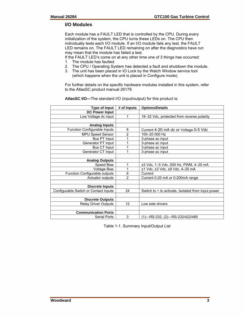
(which happens when the unit is placed in Configure mode). For further details on the specific hardware modules installed in this system, refer to the AtlasSC product manual 26179. AtlasSC I/O—The standard I/O (input/output) for this product is:
Type of Input # of Inputs Options/DetailsDC Power Input
Low Voltage dc input 1 18–32 Vdc, protected from reverse polarity
Analog InputsFunction Configurable Inputs 6 Current 4-20 mA dc or Voltage 0-5 Vdc
MPU Speed Sensor 2 100–20 000 Hz Bus PT Input 1 3-phase ac input
Generator PT Input 1 3-phase ac input Bus CT Input 1 3-phase ac input
Generator CT Input 1 3-phase ac input
Analog OutputsSpeed Bias 1 ±3 Vdc, 1–5 Vdc, 500 Hz, PWM, 4–20 mA
Voltage Bias 1 ±1 Vdc, ±3 Vdc, ±9 Vdc, 4–20 mA Function Configurable outputs 6 Current
Actuator outputs 2 Current 0-20 mA or 0-200mA range
Discrete InputsConfigurable Switch or Contact inputs 24 Switch to + to activate, Isolated from input power
Discrete Outputs
Relay Driver Outputs 12 Low side drivers
Communication PortsSerial Ports 3 (1)—RS-232, (2)—RS-232/422/485
Table 1-1. Summary Input/Output List

GTC100 Gas Turbine Control Manual 26284
4 Woodward
Software Application Program The application program is designed by using the Woodward GAP™ Graphical Application Program. The GAP program, which runs on a standard PC (personal computer), builds and compiles the application program file. This application code is then processed through a coder/compiler, which generates the application program code. This executable code is then loaded into memory on the CPU module circuit board. The GTC100 application is designed as a fuel control for a single-shaft gas turbine and is intended to provide proper fuel demand control from the initial ‘Fuel On’ signal to ‘Fuel Off’. The GTC100 control, as delivered from Woodward, also contains software options to provide turbine start/stop sequencing logic. It contains configurable start permissives and can control the turbine motor starter, ignitors, and positive fuel shutoff valves (block valves) in addition to the fuel-metering valve for both Gas and Liquid fuels. The unit with the PowerSense option includes monitoring of the generator and Bus power, synchronization and load sharing. The application also allows the user to take some of the GTC programmed I/O signals and reallocate them for a site specific use for some off-turbine package sub-system indication, or plant process requirements. Specifics on the options available for customer signals are in the fuel control Input / Output signal section. In summary, the GTC100 can be configured to provide complete automated control of a gas turbine from start to light off, to rated speed, synchronization, breaker closure and ramp up to full load set point.
A separate and independent overspeed trip device is always required to be installed to prevent possible serious injury from an over speeding prime mover.
Manual 26284 GTC100 Gas Turbine Control
Woodward 5
Chapter 2. Description of Operation
Introduction This chapter describes the operation and features included in the GTC100 system for control of a gas turbine driving a generator or a compressor. The purpose of the chapter is to provide a clear understanding of the functions and features that are available in this Woodward GTC product
Scope The control has been divided into major functions for this description. Many of these functions have sub-functions, and all of these may not be utilized in your specific unit. The major functions of this AtlasSC™ Digital Control System include: • Start Sequence Options • Control Loop Functions • Synchronization Logic • Load Control Options • Generator Protection
Start Sequence Options The sections below will provide insight as to the options programmed into the GTC for starting the gas turbine. The functional block diagram (Figure 2-1) will provide an overview of the startup sequence, the specific details of setting up the start options for each sequence step are found in Chapter 6. • Configurable Start/Stop Sequencing Logic • Turbine Lite-Off and Flameout Detection • Start Ramp and Start Control Logic • Optional EGT start temp limiter Start Ramp/Start Control The control contains options for Start mode, including an open loop start ramp and an EGT-temperature-controlled start. This control mode accelerates the turbine from initial ‘Lite-off’ to a point where the PT speed control PID can take control of the fuel valve demand. Once speed control is reached the start ramp is taken to 100%. Purge Cycle Sequence The control will allow the turbine to crank on the starter motor for the amount of time that the user configures for the purge time. This allows for any required purge of the internal turbine air and any downstream boiler system, if no boiler is present then this time can be minimized. Once this timer is complete the control will move to the Attempt Lite-off step

GTC100 Gas Turbine Control Manual 26284
6 Woodward
Figure 2-1. GTC100 Start Sequence Logic Flow Diagram Attempt Lite-off / Activate Fuel Shutoff Valves & Ignitor At this step, the control will issue relay commands to open the fuel shutoff valves for the selected fuel type and turn on the ignitors. The control will wait for the configured time to see that a flame has been established in the combustor (via one of the selected options for flame detection). If the control does not get this indication then a shutdown command is issued and annunciated as a Failed to achieve Lite-off. Once Lite-off is achieved the sequence proceeds to the Lite-off and Accel step.
Start Sequence
Initiate Start Sequence- Engage Starter / Check for Speed
Attempt Turbine Lite-Off- Activate Block Valves & Ignitor
- Fuel Metering Valve Lite-off position- Check for combustor flame
Purge Cycle- Tunable Starter Crank Time
Lite-Off and Accelerate to PT Idle- Valve ramp and/or EGT ramp
- Check for stagnation / starter cut-out
Warmup at PT Idle- Tunable Warmup timer
Accelerate to PT Rated- Tunable ramp rate to Rated Speed
Reached PT Rated Speed- Stable PT control at Rated Speed
- Check options for Sync & Load
Start Sequence Complete
Manual 26284 GTC100 Gas Turbine Control
Woodward 7
Lite-off and Accel to PT Idle Speed At this step, the control begins to ramp open the fuel start ramp and will continue on this control, or one of the other start mode options, up to the minimum PT speed set point. During this acceleration the PT speed will pass through the Starter cutout speed, which is when the Motor Starter relay will drop out. The control has a configurable timer during which it must reach the minimum PT speed set point (PT Idle). If it does not reach PT idle within this time frame a shutdown command is issued and annunciated as a PT Failed to Accel. Once PT Idle is reached then the sequence proceeds to the Warm-up step. PT Idle Warm-up Cycle Sequence At this step, the control will hold the unit at the PT Idle speed for the amount of time configured by the user. At the end of this cycle the unit will issue a pulse to begin ramping the PT reference to the rated set point. At this point the sequence proceeds to the Accelerate to PT Rated step. Accelerate to PT Rated Sequence At this step, the control will begin to raise the PT reference at the default or fast ramp rate, as determined by the user. If PT control at rated speed is not achieved in the configured time allowance then a Shutdown command is issued and annunciated as PT Failed to Accel. It is important to set this timer to a calculated amount of time in which the PT should reach rated speed (using the programmed ramp rate and rpm range between Idle and Rated). Once the unit achieves control at PT Sync the sequence proceeds to the Reached PT rated speed step. Reached PT Rated Sequence At this step, the control looks to determine that the turbine is in PT speed control at rated PT speed. Once this is confirmed the Start Sequence is completed.
Control Loop Functions The sections below will provide insight as to how the control application software implements the functions shown in the functional block diagram (Figure 2-2). • Ambient Temperature Sensing • Single Shaft Speed Sensing (w/ Redundant probes) • Turbine Inlet Temperature Sensing • Compressor Discharge Pressure (CDP) Sensing • Exhaust Gas Temperature (EGT) Sensing • PT Speed Reference Logic • Remote Speed Reference Logic • Speed Control of Power Turbine Shaft (PT) • Load Control of Power Turbine • CDP Limiting Control • EGT Limiting Control • Kilowatt Limiting Control • Acceleration and Deceleration Control • Fuel Actuator Demand and Fuel Transfer Logic
GTC100 Gas Turbine Control Manual 26284
8 Woodward
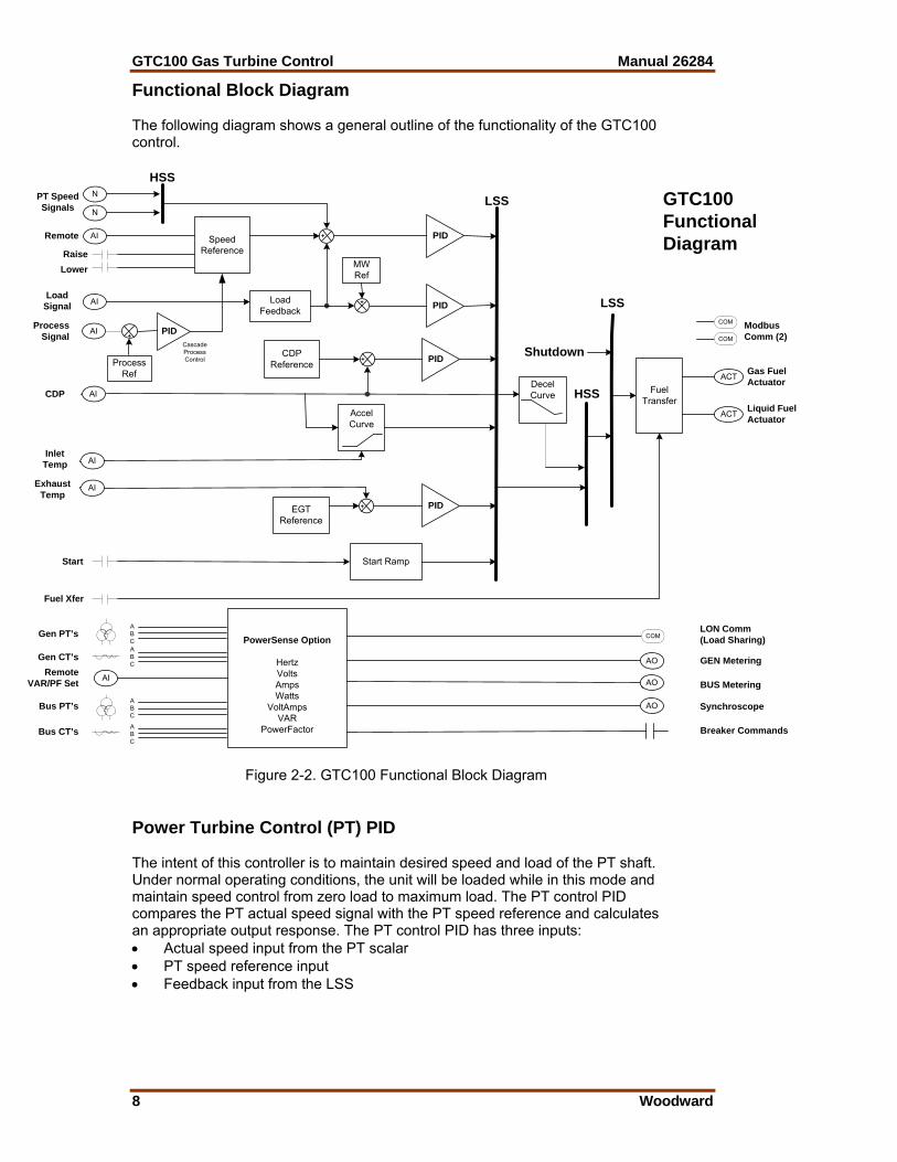
Functional Block Diagram The following diagram shows a general outline of the functionality of the GTC100 control.
Figure 2-2. GTC100 Functional Block Diagram Power Turbine Control (PT) PID The intent of this controller is to maintain desired speed and load of the PT shaft. Under normal operating conditions, the unit will be loaded while in this mode and maintain speed control from zero load to maximum load. The PT control PID compares the PT actual speed signal with the PT speed reference and calculates an appropriate output response. The PT control PID has three inputs: • Actual speed input from the PT scalar • PT speed reference input • Feedback input from the LSS
SpeedReference
N
N
AI FuelTransfer
ACT
AI
DecelCurve
PT SpeedSignals
CDP
Start
Fuel Xfer
Gas FuelActuator
HSS
LSS
HSS
GTC100FunctionalDiagram
AccelCurve
Start Ramp
PID+EGTReference
ExhaustTemp
ACT Liquid FuelActuator
LON Comm(Load Sharing)
AILoad
Signal
PID+
LoadFeedback
CDPReference
Remote
RaiseLower
AI
InletTemp
PID+
PID
MWRef
+ LSS
Shutdown
ModbusComm (2)
AI
Gen PT’s
Bus PT’s
Gen CT’s
Bus CT’s
PowerSense Option
HertzVoltsAmpsWatts
VoltAmpsVAR
PowerFactorABC
ABCABC
ABC
GEN Metering
BUS Metering
Synchroscope
Breaker Commands
AIRemoteVAR/PF Set
COM
COM
COMAIProcess
Signal PID+
ProcessRef
CascadeProcessControl
AO
AO
AO
Manual 26284 GTC100 Gas Turbine Control
Woodward 9
ACCEL Control (Curve Schedule) The acceleration schedule determines the maximum amount of fuel allowed, during acceleration. The configuration of this function is required to protect the turbine from over fueling. This demand is driven by a configurable curve based on CDP. The CDP versus Fuel Demand accel limit curve will determine the maximum amount of fuel allowed for the current CDP. This fuel demand limiter feeds into the LSS bus. If this value is the lowest on the LSS, then its schedule controls the LSS output. Temperature Limiting Control (EGT) PID The intent of this controller is to limit the maximum Exhaust Gas Temperature of the turbine. The EGT PID block compares the actual EGT signal with the reference EGT signal and generates an appropriate output response signal. The EGT control PID is typically used as a limiter on the high end of the load curve of the turbine. It is also used in the GTC as an option on startup to limit the fuel flow until closed loop speed control can be reached. It will limit the fuel demand to the turbine once the EGT temperature reaches the EGT reference set point. There is an option to switch between a Base setpoint and a Peak setpoint by configuring the unit to utilize a Discrete input to select between the 2 operating modes. The EGT Control PID has three inputs: • Analog Input signal of EGT or Alternate Turbine Inlet Temp • EGT temperature reference set point • Feedback from the LSS There is an option to use the EGT Temperature Control PID as a limiter on the calculated turbine inlet temperature (CTIT). Configuration options are available to use this option if a direct temperature signal of the limiting temperature parameter cannot be obtained. Additional alarms and shutdowns are available if this optional logic is used. There is also a CTIT setpoint curve (driven by PT Speed) that is configurable via Control Assistant/WinPanel (EGT_REF.CIT_SPD). It is a 2D curve with two sets of X-Y curves, one at compressor inlet temp (CIT) of –40 and one at CIT of 130. The X input is the PT speed and the Y output is the CTIT setpoint temperature. Kilowatt Limiting Control (KW_LIM) PID The intent of this optional controller is to limit the maximum KW output of the turbine/generator. The KW PID block compares the actual KW signal (or calculated KW load based on turbine CDP) with the reference KW signal and generates an appropriate output response signal. The KW control PID is typically used as a limiter on the high end of the load curve of the turbine. It will limit the fuel demand to the turbine once the KW output reaches the KW reference set point. The KW Control PID has three inputs: • Actual or calculated KW load input • KW limiter reference set point • Feedback from the LSS

GTC100 Gas Turbine Control Manual 26284
10 Woodward
Pressure Limiting Control (CDP) PID The intent of this controller is to limit the maximum Compressor Discharge Pressure (which equates to load) of the turbine. The CDP PID block compares the actual CDP signal with the reference CDP signal and generates an appropriate output response signal. The CDP control PID is typically used as a limiter on the high end of the load curve of the turbine. It will limit the fuel demand to the turbine once the CDP pressure reaches the CDP reference set point. The CDP Control PID has three inputs: • CDP input signal • CDP reference set point • Feedback from the LSS LSS Bus The low signal select (LSS) bus selects the lowest of the PT PID, EGT PID, CDP PID, KW Limiter, Start Ramp, or the accel schedule signals, and passes it to the HSS bus. Whichever signal is calling for the lowest fuel is the one used for LSS bus output. DECEL Control (Curve Schedule) The deceleration schedule determines the minimum amount of fuel allowed during deceleration. The configuration of this function is required to protect the turbine from lean-blowout (loss of flame) during load transients. This demand is driven by a configurable curve based on CDP. The CDP versus Fuel Demand decel limit curve will determine the minimum amount of fuel allowed for the current CDP. The correct setup of the Decel control curve will result in the turbine recovering to synchronous speed after a load drop (as in a breaker open event). Without decel control the speed control will typically pull the fuel demand back to zero percent when the speed rises at the initialization of the load drop event, which usually results in a flameout Shutdown of the turbine. This fuel demand limiter feeds into the HSS bus. If the value is the highest on the HSS, then its schedule controls the HSS.
Improper setup of the Decel Control options can result in this control loop opening (or limiting closure of) the fuel valve while all other control loops are requesting minimum fuel demand.
HSS Bus The HSS bus receives the output of the LSS bus and the decel schedule as inputs. Whichever of these inputs is higher will be the signal sent to the output of the HSS bus. This output is responsible for setting the turbine fuel valve position to maintain the requested turbine parameter. LSS Bus (LSS_2) A second low signal select (LSS) bus exists downstream of the HSS. This is where the Shutdown command is invoked to chop fuel flow to the turbine.

Manual 26284 GTC100 Gas Turbine Control
Woodward 11
Fuel Demand This block is the true 0–100% fuel demand being commanded from the fuel control. All signals of the PIDs up to the LSS_2 logic are 0 to 1. Actuator Driver The actuator driver output converts the 0-to-100% software control signal into a proportional actuator drive current signal. This can be configured for a 4–20 mA or 0–200 mA drive signal. An input from the shutdown input can override the control signal and cause the actuator to go to minimum-fuel position or shutdown. The shutdown circuit also has short and open coil fault detection. The actuator translates the signal from the electronic control into mechanical force to position the fuel valve. There are separate actuator drive outputs for gas and liquid fuel. Fuel Transfer Logic The control has the capability to run on gas or liquid fuel and the ability to make on-line fuel transfers between the two fuels. It is important to note that the packager/user will need to gather the necessary fuel property and valve flow schedule information to correctly configure the unit to make smooth on-line fuel transfers. Discrete output indications are available to indicate operation on full, gas, full liquid, or transfer in progress. There are also separate rates available for setting the desired time to make the fuel transfer in either direction.
Recommended transfer times are 20–60 seconds. If fuel transfers faster than this are required, the system should be reviewed to ensure safe and reliable operation. Flame detectors (not EGT or Speed indication options) are recommended for these applications.
Flameout Detection Logic (UV) The Flameout section of this control includes the following options: • EGT Temperature Monitoring (Option 1) • UV Detector (discrete inputs) Sensing (Option 2) • Uses EGT Temp OR UV Detection to indicate flame (Option 3) • Speed Monitoring (Option 4) EGT Temperature Monitoring The control uses EGT temperature logic to monitor for a ‘Lite-off’ detection in the combustor. This set point for this software switch is set at 400 °F (204 °C). If during any valid turbine running sequence the EGT temperature drops below this level, the control will consider this a lost flame condition and initiate a shutdown. Flame Detectors Sensor If a Ultra-Violet (UV) or other type of flame detector is used, the control will monitor this signal to confirm that ignition exists in the combustor. Flame is recognized by the control by a True signal on the discrete input contacts. Speed Monitoring This method monitors the PT shaft for speed to be greater than a programmed set point. Once this speed is reached, the control monitors for the speed to drop 200 rpm below this speed to determine that the unit has flamed out.
GTC100 Gas Turbine Control Manual 26284
12 Woodward
Synchronization Logic The GTC100 control uses digital signal processing techniques to derive both true RMS voltages and relative phase of the fundamental frequencies of the bus and generator voltage wave forms. Digital signal processing techniques offer significantly improved measurement accuracy in the presence of waveform distortions, particularly since the phase measurement does not depend on zero crossings of the waveforms. Either phase matching or slip frequency synchronizing may be selected. Phase matching method controls the turbine speed to give zero speed error and minimal phase error between the generator and bus; this provides rapid synchronizing for critical standby power applications. Slip frequency synchronizing guarantees a fixed speed difference between generator and bus. This insures the generator to be faster than the bus and initial power flow is out of the machine for larger generators. For both synchronizing methods, the GTC100 control uses actual slip frequency and breaker delay values to anticipate a minimum phase difference between bus and generator at actual breaker closure. The synchronizer can sense a dead local bus and close the generator circuit breaker automatically when safe to do so. The network communication between GTC100 controls assures that multiple generators cannot close simultaneously onto a dead bus. There are four synchronizer modes of operation: Run, Check, Permissive, Off. The mode can be selected through Watch Window or Modbus. The last mode selected by any of these interface methods will be the mode of operation. Additional synchronizer features include: voltage matching, time delayed automatic multi-shot re-closing, and a synchronizer timeout alarm. Raise and lower inputs can be used to manually adjust speed for manual synchronizing. Voltage raise and lower inputs can be used to manually adjust voltage for manual voltage matching. Each of these features may be enabled or disabled during setup.
Load Control Options The GTC100 control includes several different load control options: • Simple load droop operation provides safe operation in parallel bus
applications in the event of a circuit breaker aux contact failure. • Isochronous operation when the bus is isolated. • Isochronous Load Sharing with other units connected to the bus • Process Control • VAR/Power Factor Control When the generator circuit breaker is closed, the GTC100 can be in simple droop mode or in Isochronous Load Share mode. In the system configuration menu the user can determine the initial mode the unit will go into based upon the Generator breaker closure. The unit can go to a minimum load set point (manual loading) or go to a ‘Base’ Load set point programmed by the user (auto loading). Both of these are Droop mode load control loops. The user may also select that the unit stay in Isochronous mode which will allow it to immediately load share with any other units on the local bus. It will do this via the LON communication port, which interfaces to the other units. If this unit is the only one on the bus it will pick up all of the load.
Manual 26284 GTC100 Gas Turbine Control
Woodward 13
Load and unload ramps provide smooth transition between auto-loading, manual loading, Isochronous Load sharing and process control any time the operating mode is changed. Process Control A cascade process controller is provided for controlling load based on a customer input signal. A typical example of this is to use the process control for import/export control of generated power. An adjustable bandwidth input filter, flexible controller adjustments, an adjustable deadband, and direct or indirect control action, allow the process control to be used in a wide variety of applications. A 4–20 mA (or 1–5 Vdc) process transmitter provides the process signal to the GTC100 control. The control includes an internal digital process reference set point controlled by raise and lower switch contacts or by a Modbus or Serving communication interface. The output of the process control provides the cascade load reference to the Load control. Adjustable ramps allow smooth entry to or exit from the process control mode. When the process control mode is selected, an adjustable ramp moves the load reference in a direction to reduce the process control error. When the error is minimized, or the reference first reaches either the specified high or low load pick-up limits, the process controller is activated. When unloading from the process control, an adjustable unload ramp provides time controlled unloading to the unload trip level. When load reaches the unload trip level, the GTC100 control automatically issues a breaker open command to remove the generator set from the system. The ramp pause switch input allows holding of the load ramp for cool-down or warm-up purposes. When multiple gensets and GTC100 controls are connected to a bus in process control mode one unit is automatically assigned as the “Process Master”. Its process control loop then dictates through the LON network the load levels of other gensets on the bus. VAR/PF Control The VAR/PF functions control the reactive power component of the generator in parallel systems. The reactive load mode can be configured for VAR or Power Factor control. The controller compares the reactive load on the generator with an adjustable internal reference and makes corrections to the set point of the Automatic Voltage Regulator (AVR) until the desired reactive power is obtained. The reactive power level can be maintained while also controlling real load through the generator breaker. The analog voltage bias output can be directly connected to compatible voltage regulators. The control also has raise and lower contact outputs to activate a voltage regulator MOP when an analog input is not provided on the AVR. The GTC100 control has a selectable voltage range alarm that is activated if the analog output to the voltage regulator reaches high or low saturation. The GTC100 control also has selectable and adjustable high and low voltage limit switches and alarm outputs. The GTC100 control provides switch inputs to allow raising or lowering the generator voltage reference. The control also provides a 4–20 mA (or 1–5 Vdc) analog input for kVAR/PF set point control, if desired. The kVAR/PF reference can also be set through a Modbus or ServLink DDE communication interface.

GTC100 Gas Turbine Control Manual 26284
14 Woodward
While the GTC100 is controlling unit load to accomplish real load (kW) sharing, the voltage of the generators in parallel will be controlled to accomplish equal Power Factor levels of each generator.
Generator Protection The GTC100 control with the PowerSense Module includes the following features as selection options for the user. Power and Energy Metering The digital signal processing techniques are used to provide significantly improved accuracy and speed of response over conventional analog measurement techniques. Accuracy is improved using rapid sampling of the voltage and current signal waveforms and developing a true RMS measurement. Measuring true RMS power allows optimal accuracy, even in the presence of power line distortions. The PowerSense board receives the PT and CT inputs for both the generator and bus for calculation of parameters for the GTC100 to use in system control. The algorithms used are based on IEEE 1459-2000. For the generator and bus the following parameters are provided: Hz, Vac, Amps, W, VA, VAR, PF, Phase, Voltage harmonics, Current harmonics, Negative Phase Sequence Voltage, Negative Phase Sequence Current. Available for selection at the 4–20 mA analog outputs: Synchroscope, Generator metering, Mains metering Protective Relaying Alarms and Trips can be configured for generator protective relay functions. Time delays for the alarm and trip thresholds can be set. The GTC100 contains programming logic to annunciate the following generator events: • Over and Under Voltage • Over and Under Current • Over and Under Frequency • Over and Under VARs • Negative Phase Current and Voltage • Phase Over Current • Phase Differential Current • Reverse Power and Over Power protection Each of the events has an initial Warning level and an Alarm level condition that can trigger the desired action (Alarm, Open Breaker Trip, Shutdown unit Trip). Current based protections are implemented using the ANSI/IEEE C37.112 Very Inverse curve.
Manual 26284 GTC100 Gas Turbine Control
Woodward 15
Special Features of the GTC The GTC100 also contains a few special features that the user may be interested in using. These tools may require the user to have a deeper level of understanding of the Woodward control and software products than is required to just configure and run the unit. However, anyone capable of commissioning a unit should be able to utilize these features, and instruct others on how & when to use them. Debug Tunables—There are additional tunables in the control application that are not available in the service and configure headers. These are intended to be used only if needed by experienced personnel. Non-Volatile Memory—The application has logic that will keep an incremental count of the following: • Number of Starts Attempted • Number of Fired Starts (Start & Temp seen) • Number of Shutdowns (Hard shutdowns only) • Total Turbine Run Hours (Fuel On & Temperature seen) The control will save these values periodically to a non-volatile memory location so that these values will not be lost upon a power cycle to the control. These accumulated values are sent to the Modbus list. There are tunable handles in the application to preset these accumulators to any desired value when the control is being initially installed or when the control is replaced. Data logging—The GTC has a high-speed datalog block included in the application that allows the control to trend a pre-programmed number of parameters at a rate of 10 ms increments. These values are stored in an accumulation buffer that will retain approximately 2 minutes of run time. These block is setup to automatically start once the turbine is achieved a successful start and will automatically stop the log anytime a shutdown event occurs. It will retain the data in the buffer until it is either downloaded to a serial port or a new start command is issued to the datalog block. It is important to realize that this file must be retrieved before attempting a restart or the file will be lost. This file can be downloaded and viewed with the Control Assistant tool. This file can be very valuable in troubleshooting dynamic control issues or intermittent shutdowns.

GTC100 Gas Turbine Control Manual 26284
16 Woodward
Chapter 3. Installation and Wiring Guidelines
Introduction For general information on unpacking the unit, mounting the unit, shielding and grounding signals refer to the AtlasSC digital control manual (26179). This chapter is intended to guide the user in specific control wiring of the I/O signals used in the GTC100 application.
Electrical Connections For noise suppression, it is recommend that all low-current wires be separated from all high-current wire. Most inputs and outputs to the GTC100 are made through “CageClamp” terminal blocks. The GTC100 is shipped with mating connectors for all terminals. Most of the GTC100 control’s terminal blocks are designed for removal by hand. After GTC100 input power is disconnected, the pluggable terminal blocks can be removed one at a time by pulling them straight out. Be careful not to pull the plug out at an angle, as this will fracture the end terminal. Each Terminal block has a label (PS, PSEN, SCM) to indicate which board it is used with, and terminal numbering to indicate which terminal block on that board to plug into. The board assemblies also are marked with a label to match with terminal block labels. The pluggable terminal blocks are screwless CageClamp-style blocks. The spring clamp can be opened with a standard 2.5 mm (3/32 inch) flat bladed screwdriver (see Figure 2-2). The GTC100 pluggable terminal blocks accept wire 28 to 18 AWG (0.08 to 0.8 mm²). One 18 AWG (0.8 mm²) wire, or two 20 AWG (0.5 mm²) wires, or three 22 AWG (0.3 mm²) wires can be easily installed in each terminal. Wires for the pluggable I/O terminals should be stripped 8 mm (0.3 inch). The GTC100 fixed terminal blocks used for the power supply input accept wires from 28 to 18 AWG (0.08 to 0.8 mm²). One 18 AWG (0.8 mm²) wire, or two 20 AWG (0.5 mm²) wires, or three 22 AWG (0.3 mm²) wires can be easily installed in each terminal. Wires for the fixed mounted power terminals should be stripped 5 mm (0.2 inch).
Do not tin (solder) the wires that terminate at the GTC100 terminal blocks. The spring-loaded CageClamp terminal blocks are designed to flatten stranded wire, and if those strands are tinned together, the connection loses surface area and is degraded.
All ac wiring for voltages and currents is done with fixed screw barrier blocks rather than pluggable terminal blocks. The fixed screw barrier blocks accept wires terminated into terminal lugs for #6 screws.

Manual 26284 GTC100 Gas Turbine Control
Woodward 17
Figure 3-1. Fixed Ring Terminals
Grounding for Protection against Electrical Shock Protective Earth (PE) must be connected to the termination point on the backside
of the unit next to the label with the symbol (or 1 of 3 other like termination points without label) to reduce the risk of electric shock. This connection will be made using a thread-forming screw (M4 x 6 mm). The conductor providing the connection must have a properly sized ring lug and wire larger than or equal to 3.3 mm² (12 AWG). Recommended Grounding Practices Providing the proper ground for the GTC100 is important. Improper connection of the GTC100 chassis to the ground plane may lead to stray currents between the reference point for the ac signal sources (current and voltage transformers), and the reference point for the sensing inputs on the GTC100. Differences in potential between these two points results in equalizing current flow which then produces unacceptably high common mode voltages. Common mode voltages may result in improper readings for the sensed ac inputs, or even damage to the GTC100 in extreme cases. To minimize this problem, it is necessary to provide a low resistance path between the ac signal reference point, and the chassis of the GTC100. Typically this point is the designated ground for the generator set and related instrument transformers. Isolation Figure 3-3 shows how the I/O is isolated with regard the main system power supply and other I/O types. Each input wiring diagram also shows how an input type is isolated in more detail.
GTC100 Gas Turbine Control Manual 26284
18 Woodward
Back of GTC
TB 1 TB 2 TB 3 TB 4
TB 5 TB 6 TB7 TB8 TB9
GTC100 chassis groundlug connection point (4)
Generator
Ground Bonding Conductor
VIS-14400-8-23
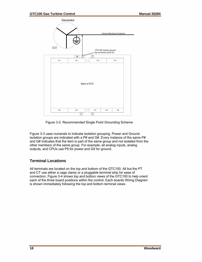
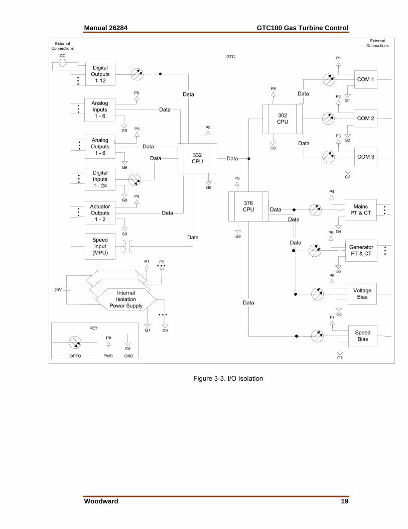
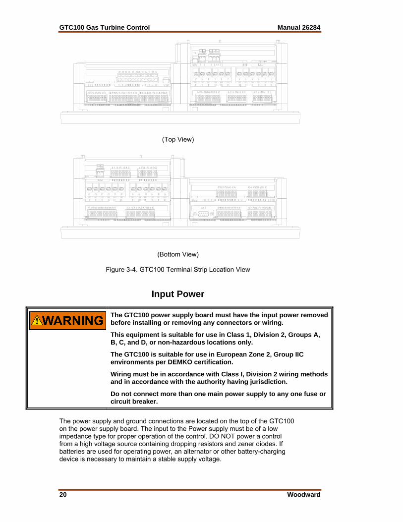
Figure 3-2. Recommended Single Point Grounding Scheme Figure 3-3 uses numerals to indicate isolation grouping. Power and Ground isolation groups are indicated with a P# and G#. Every instance of the same P# and G# indicates that the item is part of the same group and not isolated from the other members of the same group. For example, all analog inputs, analog outputs, and CPUs use P9 for power and G9 for ground. Terminal Locations All terminals are located on the top and bottom of the GTC100. All but the PT and CT use either a cage clamp or a pluggable terminal strip for ease of connection. Figure 3-4 shows top and bottom views of the GTC100 to help orient each of the three board positions within the control. Each boards Wiring Diagram is shown immediately following the top and bottom terminal views.
Manual 26284 GTC100 Gas Turbine Control
Woodward 19
SpeedInput
(MPU)
SpeedBias
VoltageBias
AnalogInputs1 - 6
AnalogOutputs
1 - 6
DigitalOutputs
1-12
GeneratorPT & CT
MainsPT & CT
DigitalInputs1 - 24
332CPU
302CPU
376CPU
Data
Data
Data
Data
G8
COM 1
COM 2
COM 3Data
Data
DataG1
G2
G3
G4
G5
G6
G7
Data
Data
Data
Data
Data
24V
DC
ExternalConnections
G9
G9
P9
P9
P2
P3
P1
P5
P6
P7
P4
P9
P9
P9
G9
G9
G9
InternalIsolation
Power Supply
......
......
......
P1 P9...
G1 G9
...
ExternalConnections
GTC
P#
G#
KEY
OPTO PWR GND
ActuatorOutputs
1 - 2
G9
P9
... Data
Figure 3-3. I/O Isolation
GTC100 Gas Turbine Control Manual 26284
20 Woodward
(Top View)
(Bottom View)
Figure 3-4. GTC100 Terminal Strip Location View
Input Power
The GTC100 power supply board must have the input power removed before installing or removing any connectors or wiring.
This equipment is suitable for use in Class 1, Division 2, Groups A, B, C, and D, or non-hazardous locations only.
The GTC100 is suitable for use in European Zone 2, Group IIC environments per DEMKO certification.
Wiring must be in accordance with Class I, Division 2 wiring methods and in accordance with the authority having jurisdiction.
Do not connect more than one main power supply to any one fuse or circuit breaker.
The power supply and ground connections are located on the top of the GTC100 on the power supply board. The input to the Power supply must be of a low impedance type for proper operation of the control. DO NOT power a control from a high voltage source containing dropping resistors and zener diodes. If batteries are used for operating power, an alternator or other battery-charging device is necessary to maintain a stable supply voltage.

Manual 26284 GTC100 Gas Turbine Control
Woodward 21
GTC
3
2
1
CommonSystemGround
GND(isol) 24V
Optional
Figure 3-5. Input Power Wiring Diagram Input Power Ratings
Voltage Range 18–32 Vdc Maximum Voltage 40 Vdc Minimum Voltage 9 Vdc (engine cranking only)
Input Current 0.9 A @ 24 Vdc 1.1 A @ 18 Vdc
Maximum Input Power 22 W Typical Input Power 20 W @ 24 Vdc
Interrupt Time Holdup 8 ms @ >= 24 Vdc input voltage Efficiency 70% minimum over operating input voltage range
Reverse Polarity Protection 100 Vdc Input Wiring Constraints The GTC100 must be wired such that no other device receives
power from the wiring between the unit and the power supply source.
Input Wire Size 12 AWG (2.5 mm²) Input Fuse Rating 3 A (time delay with melting I2t 100A2 sec)
Significant inrush currents are possible when current is applied to the GTC100 control. The magnitude of the inrush current depends on the power source impedance, so Woodward cannot specify the maximum inrush current. Time-delay fuses or circuit breakers must be used to avoid nuisance trips. Power Supply Monitoring Circuit
Maximum voltage measured 35 Vdc Resolution in volts 0.15 Vdc
Maximum error due to temperature change 1.0 Vdc Maximum error due to load change 1.0 Vdc
Total maximum error at 25 °C 1.2 Vdc Input Power Wiring
Protective earth ground (PE) must be connected to the chassis at the labeled termination point on the back of the display. The power supply grounding terminals should also be connected to earth to ensure grounding of the power supply printed circuit boards. The grounding conductor must be the same size as the main supply conductors or the PT wires, whichever is larger. Note that the control’s power supplies are not equipped with input power switches. For this reason, some means of disconnecting input power to each main power supply must be provided for installation and servicing.

GTC100 Gas Turbine Control Manual 26284
22 Woodward
It is expected that the installation of this equipment will include overcurrent protection between the power source and the GTC100. This overcurrent protection may be accomplished by series connection of properly rated fuses or circuit breakers. Branch circuit protection of no more than 250% of the maximum GTC100 power supply input current rating must be provided. Maximum fuse rating must meet the 250% UL listing requirements. The use of properly sized UL class CC, J, T, G, RK1, or RK5 fuses meet the requirements for branch circuit protection. Do not connect more than one GTC100 to any one fuse. Use only the wire size specified above, or equivalent, that meets local code requirements. Time delay fuses should be used to prevent nuisance trips. The power supply holdup time specification is the time the supply will continue to operate within specification after its input power is interrupted. This information may be useful in specifying uninterruptible power supply (UPS) systems.
2.5 mm² (12 AWG) is the largest wire gauge size that can be connected to the control power input terminal blocks. The minimum continuous input voltage allowed is 18 V at the power input of the control. The length, size of wire, and load current will determine the minimum supply output voltage. The minimum supply voltage measured at the source should always be greater than 18 V. Example: two (source and return) 20 foot (6 m) lengths of 14 AWG (2.5 mm²) wire carrying 1.2 A (maximum rated current) will result in a voltage drop from source output to control power input of approx. 0.16 volts. The resulting supply voltage from the example must be greater than 18.16 volts. The GTC100 will remain in operation when an electrical starter is engaged, if input power drops to no less than 9.0 V.
Manual 26284 GTC100 Gas Turbine Control
Woodward 23
Chapter 4. PowerSense Signal Wiring
PowerSense Board Wiring Pinout The PowerSense board (PSEN) is mounted between the Power Supply and the SmartCore board. The PowerSense Board inputs are the Mains and Generator power monitoring. Each PowerSense board contains the circuitry for two sets of three phase ac voltage (PT) and ac current (CT) inputs, as well as a speed bias output, a voltage bias output, and a LON communications port. Features • On-board processor for automatic calibration of the I/O channels • PT and CT inputs provide fundamental as well as harmonic information • PT and CT inputs are updated after 3 cycles, which is 50 ms at 60 Hz • PT and CT inputs and bias outputs have 12 bit resolution • PT inputs are software configurable for 70 V, 120 V, or 240 V ranges • Each set of PT and CT inputs is isolated from the rest of the board and
chassis • Speed bias output is software configurable for 4–20 mA, 0–5 V, PWM, or ±3
V output • Voltage Bias output is software configurable for 4–20 mA, ±1 V, ±3 V, and
±9 V • Speed Bias and Voltage bias outputs are isolated from the rest of the board • LON communication port
Potential Transformer (PT) Inputs The Generator and Mains ac voltage inputs can accept voltages up to 300 Vac RMS maximum between the positive and negative terminals of each input. The inputs may be connected line-to-line or line-to-neutral. For example, if the inputs are connected line-to-neutral, each input A-N, B-N, and C-N may have up to 300 Vac. Therefore, a 480 Vac generator may be wired to the GTC100 using line-to-neutral connections resulting in 277 Vac at the inputs.
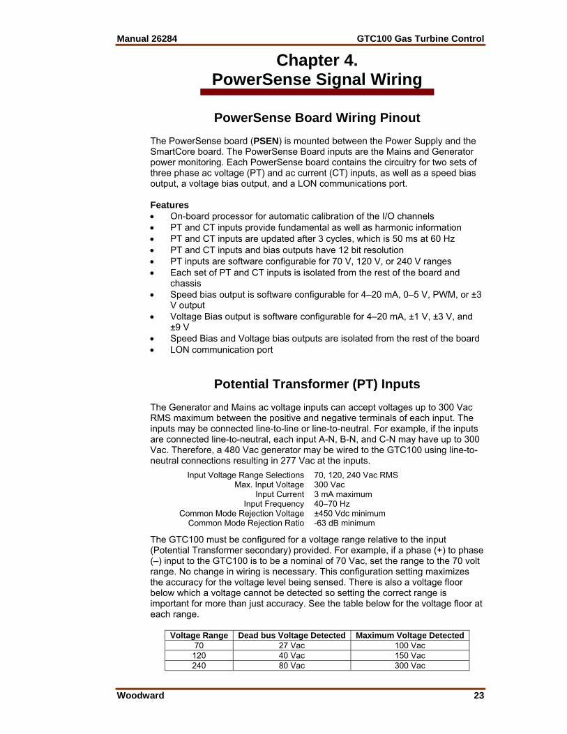
The GTC100 must be configured for a voltage range relative to the input (Potential Transformer secondary) provided. For example, if a phase (+) to phase (–) input to the GTC100 is to be a nominal of 70 Vac, set the range to the 70 volt range. No change in wiring is necessary. This configuration setting maximizes the accuracy for the voltage level being sensed. There is also a voltage floor below which a voltage cannot be detected so setting the correct range is important for more than just accuracy. See the table below for the voltage floor at each range.
Voltage Range Dead bus Voltage Detected Maximum Voltage Detected70 27 Vac 100 Vac
120 40 Vac 150 Vac 240 80 Vac 300 Vac
Input Voltage Range Selections 70, 120, 240 Vac RMS Max. Input Voltage 300 Vac
Input Current 3 mA maximum Input Frequency 40–70 Hz
Common Mode Rejection Voltage ±450 Vdc minimum Common Mode Rejection Ratio -63 dB minimum

GTC100 Gas Turbine Control Manual 26284
24 Woodward
If potential transformers are used, be careful to select an accurate transformer. The largest source of inaccuracy in the system will be the transformer, since even the most accurate transformer is less accurate than the ac voltage inputs to the GTC100. The calibration menu contains turns ratio compensation factors for each PT input. Follow the calibration procedure to negate much of the transformer error. When the PT input to the control is conditioned with a transformer the generator and mains transformer ratio is entered into the GTC100. This is described in the Configuration section of the Operation Manual. The GTC100 will use the PT ratio and the entered configured Range to calculate the actual system voltage(s). EXAMPLE: Hwd range = 120 PT ratio = 4 Measured PT secondary (input at terminals) = 112.5 Vac The GTC100 will display 450 Vac for this input voltage. Hazardous Live The following circuits are classified as Hazardous Live because they carry potential shock hazardous voltages during normal operation or under single fault conditions: • Potential transformer (PT) inputs • Current transformer (CT) inputs • Voltage bias outputs
HIGH VOLTAGE—Do not touch or make contact with the above inputs and outputs during system operation when such circuits are live. Possible serious personal injury or death could result.
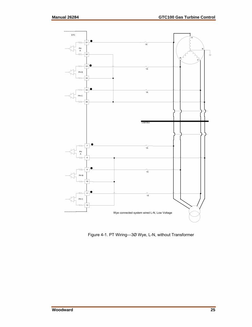
These inputs and outputs are provided with 500 V of dielectric isolation from chassis ground. In addition, these inputs/outputs are isolated from safety extra-low voltage (SELV) circuits (such as serial communication, PC/104 circuits) by optoisolators or transformers provided with double insulation and 3 000 Vac of dielectric isolation. PT—3∅ Wye, L-N, No Transformers No transformers are necessary if the voltage input to the GTC100 is less than 300 Vac at a given phase input. This diagram shows a system where both the generator and bus are less than 300 Vac measured line-to-neutral. Each is connected to the GTC100 in a L-N mode without transformers (PT Ratio = 1:1). It is not required that both the mains and the generator inputs be connected in the same manner. One could be L-L and the other L-N if preferred. Also, one could use transformers and the other not. The diagram shown is simply an example of a typical system.
Manual 26284 GTC100 Gas Turbine Control
Woodward 25
A
N
CB
GTC
31
32
33
34
35
36
PHA
PH B
PH C
1A
1A
1A
7
8
9
10
11
12
PHA
PH B
PH C
1A
1A
1A
Wye connected system wired L-N, Low Voltage
Load Bus
Figure 4-1. PT Wiring—3Ø Wye, L-N, without Transformer
GTC100 Gas Turbine Control Manual 26284
26 Woodward
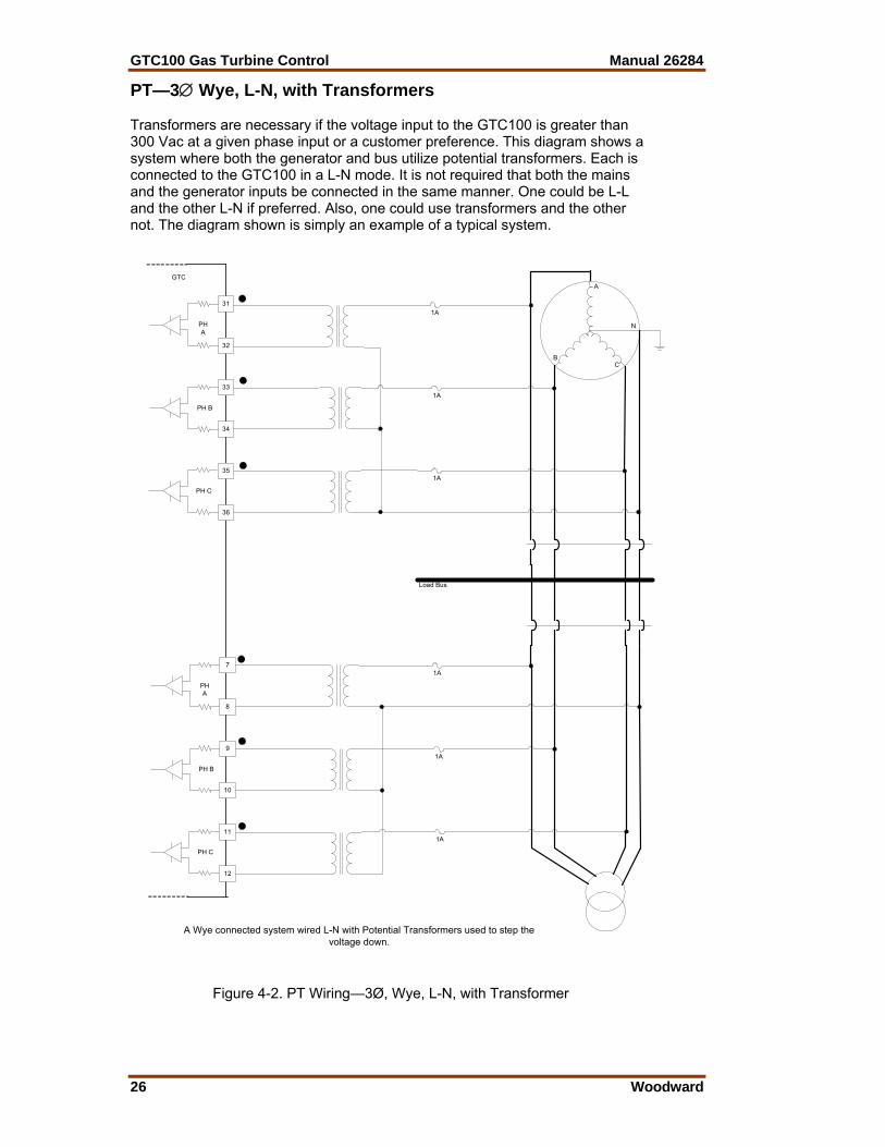
PT—3∅ Wye, L-N, with Transformers Transformers are necessary if the voltage input to the GTC100 is greater than 300 Vac at a given phase input or a customer preference. This diagram shows a system where both the generator and bus utilize potential transformers. Each is connected to the GTC100 in a L-N mode. It is not required that both the mains and the generator inputs be connected in the same manner. One could be L-L and the other L-N if preferred. Also, one could use transformers and the other not. The diagram shown is simply an example of a typical system.
A
N
CB
GTC
31
32
33
34
35
36
PHA
PH B
PH C
1A
1A
7
8
9
10
11
12
PHA
PH B
PH C
A Wye connected system wired L-N with Potential Transformers used to step thevoltage down.
1A
1A
1A
1A
Load Bus
Figure 4-2. PT Wiring—3Ø, Wye, L-N, with Transformer
Manual 26284 GTC100 Gas Turbine Control
Woodward 27
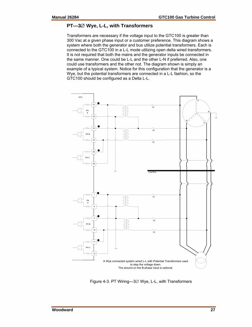
PT—3∅ Wye, L-L, with Transformers Transformers are necessary if the voltage input to the GTC100 is greater than 300 Vac at a given phase input or a customer preference. This diagram shows a system where both the generator and bus utilize potential transformers. Each is connected to the GTC100 in a L-L mode utilizing open delta wired transformers. It is not required that both the mains and the generator inputs be connected in the same manner. One could be L-L and the other L-N if preferred. Also, one could use transformers and the other not. The diagram shown is simply an example of a typical system. Notice for this configuration that the generator is a Wye, but the potential transformers are connected in a L-L fashion, so the GTC100 should be configured as a Delta L-L.
A
N
CB
GTC
31
32
33
34
35
36
PHA
PH B
PH C
1A
1A
7
8
9
10
11
12
PHA
PH B
PH C
A Wye connected system wired L-L with Potential Transformers usedto step the voltage down.
The ground on the B-phase input is optional.
1A
1A
1A
1A
Load Bus
Figure 4-3. PT Wiring—3∅ Wye, L-L, with Transformers
GTC100 Gas Turbine Control Manual 26284
28 Woodward
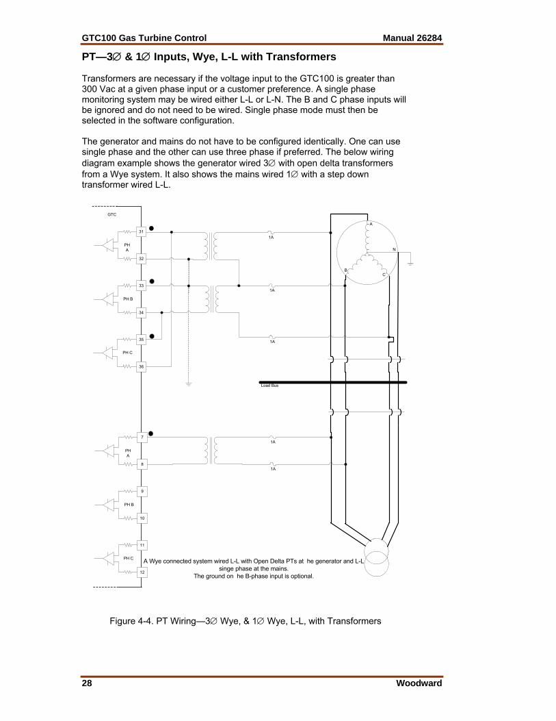
PT—3∅ & 1∅ Inputs, Wye, L-L with Transformers Transformers are necessary if the voltage input to the GTC100 is greater than 300 Vac at a given phase input or a customer preference. A single phase monitoring system may be wired either L-L or L-N. The B and C phase inputs will be ignored and do not need to be wired. Single phase mode must then be selected in the software configuration. The generator and mains do not have to be configured identically. One can use single phase and the other can use three phase if preferred. The below wiring diagram example shows the generator wired 3∅ with open delta transformers from a Wye system. It also shows the mains wired 1∅ with a step down transformer wired L-L.
A
N
CB
GTC
31
32
33
34
35
36
PHA
PH B
PH C
1A
1A
7
8
9
10
11
12
PHA
PH B
PH C A Wye connected system wired L-L with Open Delta PTs at he generator and L-Lsinge phase at the mains.
The ground on he B-phase input is optional.
1A
1A
Load Bus
1A
Figure 4-4. PT Wiring—3∅ Wye, & 1∅ Wye, L-L, with Transformers
Manual 26284 GTC100 Gas Turbine Control
Woodward 29
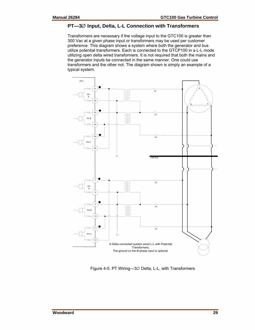
PT—3∅ Input, Delta, L-L Connection with Transformers Transformers are necessary if the voltage input to the GTC100 is greater than 300 Vac at a given phase input or transformers may be used per customer preference. This diagram shows a system where both the generator and bus utilize potential transformers. Each is connected to the GTCP100 in a L-L mode utilizing open delta wired transformers. It is not required that both the mains and the generator inputs be connected in the same manner. One could use transformers and the other not. The diagram shown is simply an example of a typical system.
GTC
31
32
33
34
35
36
PHA
PH B
PH C
1A
1A
7
8
9
10
11
12
PHA
PH B
PH C
1A
1A
1A
1A
Load Bus
A
CB
A Delta connected system wired L-L with PotentialTransformers.
The ground on the B-phase input is optional.
Figure 4-5. PT Wiring—3∅ Delta, L-L, with Transformers
GTC100 Gas Turbine Control Manual 26284
30 Woodward
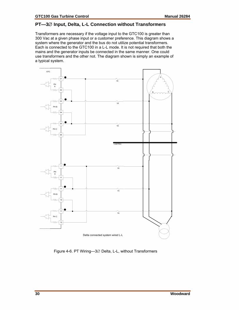
PT—3∅ Input, Delta, L-L Connection without Transformers Transformers are necessary if the voltage input to the GTC100 is greater than 300 Vac at a given phase input or a customer preference. This diagram shows a system where the generator and the bus do not utilize potential transformers. Each is connected to the GTC100 in a L-L mode. It is not required that both the mains and the generator inputs be connected in the same manner. One could use transformers and the other not. The diagram shown is simply an example of a typical system.
GTC
31
32
33
34
35
36
PHA
PH B
PH C
1A
1A
7
8
9
10
11
12
PHA
PH B
PH C
1A
1A
1A
1A
A
CB
Delta connected system wired L-L
Load Bus
Figure 4-6. PT Wiring—3∅ Delta, L-L, without Transformers
Manual 26284 GTC100 Gas Turbine Control
Woodward 31
Current Transformer (CT) Inputs The Generator and Mains ac current inputs can accept currents up to 7 A ac RMS maximum between the positive and negative terminals of each input. The CT inputs are rated at 5 A ac RMS nominal and function down to 50 mA. For optimum accuracy in the usable range, it is recommended to use 5 A secondary CTs (Do not use 1 A secondary CTs).
Input Current 5 A RMS full scale Max. Transient Input Current 7.07 A RMS
Input Frequency 40–70 Hz Common Mode Voltage ±250 Vdc minimum
Common Mode Rejection Ratio –63 dB minimum Be careful to select an accurate current transformer. The largest source of inaccuracy in the system will be the transformer since even the most accurate transformer is less accurate than the AC current inputs to the GTC100. The calibration menu contains turns ratio compensation factors for each CT input. Follow the calibration procedure to negate much of the transformer linear error. The GTC100 does not require three phases for current calculations. The user can configure the GTC100 for single phase, and all functionality will be modified accordingly. The phase input that must be provided is the A phase. The generator and mains Current Transformer ratio is entered into the GTC100. This is described in the Configuration section of the Operators Manual (26137). The GTC100 will use the CT ratio to calculate the actual system current(s). EXAMPLE: CT ratio = 500 Measured CT secondary (input at terminals) = 3.9 A The GTC100 will display 1950 A ac for this input current. For a full wiring connection, combine the Current Transformer (CT) wiring below with the Potential Transformer (PT) section above.
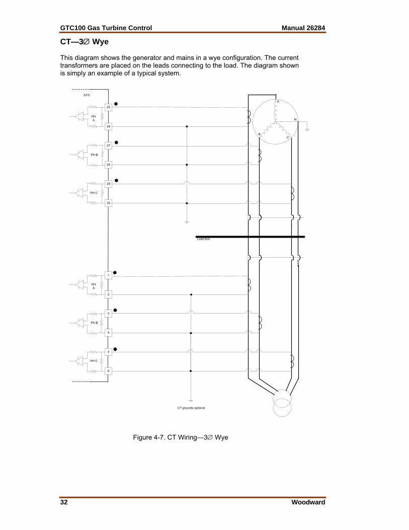
GTC100 Gas Turbine Control Manual 26284
32 Woodward
CT—3∅ Wye This diagram shows the generator and mains in a wye configuration. The current transformers are placed on the leads connecting to the load. The diagram shown is simply an example of a typical system.
A
N
CB
CT grounds optional
Load Bus
GTC
25
26
27
28
29
30
1
2
3
4
5
6
PHA
PH B
PH C
PHA
PH B
PH C
Figure 4-7. CT Wiring—3∅ Wye
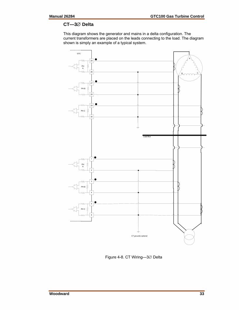
Manual 26284 GTC100 Gas Turbine Control
Woodward 33
CT—3∅ Delta This diagram shows the generator and mains in a delta configuration. The current transformers are placed on the leads connecting to the load. The diagram shown is simply an example of a typical system.
CT grounds optional
A
CB
Load Bus
GTC
25
26
27
28
29
30
PHA
PH B
PH C
1
2
3
4
5
6
PHA
PH B
PH C
Figure 4-8. CT Wiring—3∅ Delta

GTC100 Gas Turbine Control Manual 26284
34 Woodward
Single Phase Monitoring In a single phase monitoring system, the GTC100 will only use the A phase CT input. Anything connected to the B and C phase inputs will be ignored. The current transformer is placed on the A phase leads connecting to the load. See the appropriate diagram above and ignore the B and C phase inputs. For a single phase input, the PT and CT must be monitoring the same phase. During control Configuration the software must be selected to use Single Phase. The single phase monitoring is applied to 3 phase machines, it is not intended for single phase machines.
The GTC100 power calculations are based on a per-phase calculation. When a single phase input is used the displayed values will be 1/3 of the total devise levels. Therefore the entered CT ratio or the total power level(s) for the mains or generator will have to be adjusted to display actual 3∅ devise power levels.
Speed Bias Output The Speed Bias output is not used on the GTC100.
Voltage Bias Output The Voltage Bias allows the GTC100 to vary the generator voltage level to control the reactive load on the generator. The Voltage Bias can be configured one of four types of outputs: 4–20 mA, ±1 V, ±3 V, ±9 V. The output mode selected should be determined based on the voltage regulator specifications. Minimum to maximum voltage bias output change from the GTC100 should be approximately ±10% change in rated generator voltage. Both the configuration and the wiring must be changed to switch between current and voltage outputs. Only the configuration must be changed to switch between the differing voltage outputs.
PWM frequency 3 kHz for current and voltage outputs Current output 4–20 mA selected by software switch and wiring Voltage output ±1, ±3, ±9 Vdc selectable by software switch and wiring
Max current output 4–20 mA output 25 mA ±5%
Max voltage output ±1, ±3, ±9 Vdc ±9 V limit ±5%
Isolation See HAZARDOUS LIVE isolation requirement Max load resistance
4–20 mA 300 Α at 24 mA ±1, ±3, ±9 Vdc No maximum
Min load resistance 4–20 mA 0 Ω
±1, ±3, ±9 Vdc output 7 kΏ Resolution
4–20 mA 12 bits ±1 V output >7 bits ±3 V output >9 bits ±9 V output 12 bits
Accuracy Better than ±0.1% of full scale @ 25 °C 4–20 mA ±0.025 mA
±1 V, ±3 V, ±9 V output ±0.018 V Temperature Drift
Voltage outputs 330 ppm/°C, maximum 4–20 mA output 140 ppm/°C, maximum
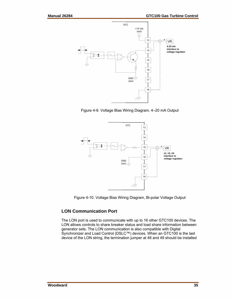
Manual 26284 GTC100 Gas Turbine Control
Woodward 35
GTC
13
14
15
+
4-20 mAinterface tovoltage regulator
16
18
VR
17
+15 Vdc(isol)
GND(isol)
Figure 4-9. Voltage Bias Wiring Diagram, 4–20 mA Output
GTC13
14
15 +
±1, ±3, ±9,interface tovoltage regulator
16
18
VR
17
GND(isol)
Figure 4-10. Voltage Bias Wiring Diagram, Bi-polar Voltage Output LON Communication Port The LON port is used to communicate with up to 16 other GTC100 devices. The LON allows controls to share breaker status and load share information between generator sets. The LON communication is also compatible with Digital Synchronizer and Load Control (DSLC™) devices. When an GTC100 is the last device of the LON string, the termination jumper at 48 and 49 should be installed
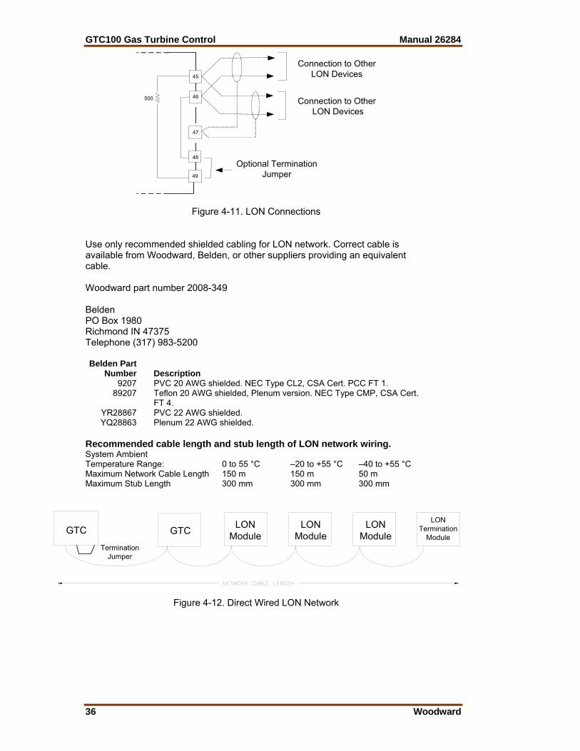
GTC100 Gas Turbine Control Manual 26284
36 Woodward
45
46
47
48
49
500
Connection to OtherLON Devices
Connection to Other LON Devices
Optional TerminationJumper
Figure 4-11. LON Connections Use only recommended shielded cabling for LON network. Correct cable is available from Woodward, Belden, or other suppliers providing an equivalent cable. Woodward part number 2008-349 Belden PO Box 1980 Richmond IN 47375 Telephone (317) 983-5200 Belden Part Number Description 9207 PVC 20 AWG shielded. NEC Type CL2, CSA Cert. PCC FT 1. 89207 Teflon 20 AWG shielded, Plenum version. NEC Type CMP, CSA Cert.
FT 4. YR28867 PVC 22 AWG shielded. YQ28863 Plenum 22 AWG shielded. Recommended cable length and stub length of LON network wiring. System Ambient Temperature Range: 0 to 55 °C –20 to +55 °C –40 to +55 °C Maximum Network Cable Length 150 m 150 m 50 m Maximum Stub Length 300 mm 300 mm 300 mm
GTCLON
TerminationModule
TerminationJumper
GTC LONModule
LONModule
LONModule
Figure 4-12. Direct Wired LON Network
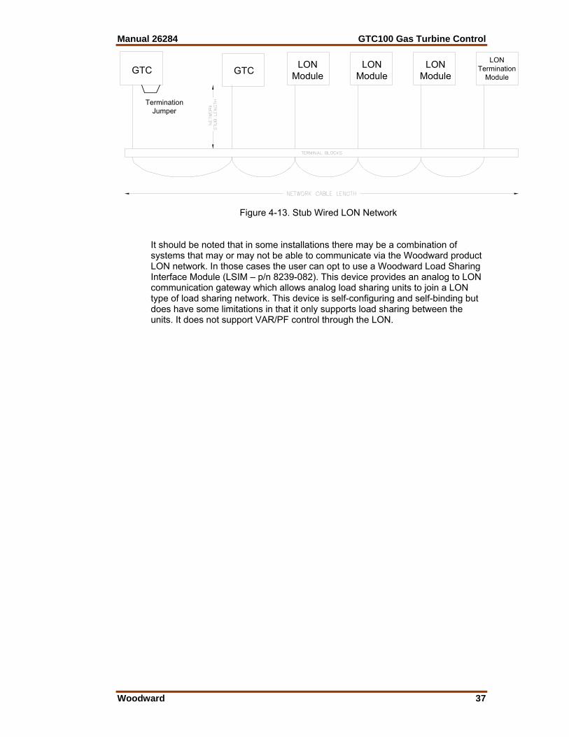
Manual 26284 GTC100 Gas Turbine Control
Woodward 37
GTCLON
TerminationModule
TerminationJumper
GTC LONModule
LONModule
LONModule
Figure 4-13. Stub Wired LON Network
It should be noted that in some installations there may be a combination of systems that may or may not be able to communicate via the Woodward product LON network. In those cases the user can opt to use a Woodward Load Sharing Interface Module (LSIM – p/n 8239-082). This device provides an analog to LON communication gateway which allows analog load sharing units to join a LON type of load sharing network. This device is self-configuring and self-binding but does have some limitations in that it only supports load sharing between the units. It does not support VAR/PF control through the LON.

GTC100 Gas Turbine Control Manual 26284
38 Woodward
Chapter 5. Control Signal Wiring
Introduction A detailed list of the AtlasSC™ I/O signal layout including channel allocation, wiring terminations, descriptions, and range information is found in Appendix A. This chapter describes details of the signals that the GTC100 is programmed to handle. The control wiring diagrams in Appendix A also identify which signals are required and which are optional. The details below show the ‘Programmed Default’ functions of the GTC100 input/output channels. This section should be used in conjunction with Appendix E which lists the information that the user will see on the Service and Configure screens when using Watch Window to configure the control. Appendix E will guide the user in the specific detailed configuration options of the control for each turbine. Most of the I/O channels in the GTC100 have been programmed with 3 options: • GTC Used—as per default allocation below and in Appendix A • Customer Use—custom signals for pre-programmed options • Not Used
Fuel Control Input/Output Signals SmartCore Board Wiring Pinout The SmartCore board (SCM) contains circuitry for the two speed sensor inputs, six analog inputs, six analog outputs, 3 serial ports, and 24 discrete inputs. The speed sensor input is from a magnetic pick-up, each Analog input may be 4–20 mA or 0–5 V, and two of the serial ports, may be RS-232, RS-422, or RS-485. The other serial port is a dedicated RS-232 port. Features • On-board processor for automatic calibration of the I/O channels • Analog inputs have 14-bit resolution • Analog outputs have 12-bit resolution • Actuator outputs have 12-bit resolution • Serial Ports are configurable
MPU (Speed) Inputs The GTC100 accepts passive magnetic pickup (MPU) inputs for speed sensing. It is not recommended that gears mounted on an auxiliary shaft be used to sense speed. Auxiliary shafts tend to turn more slowly than the rotor or crankshaft (reducing speed sensing resolution) and have coupling gear backlash, resulting in less than optimum speed detection. For safety purposes, it is also not recommended that the speed sensing device sense speed from a gear coupled to a generator or mechanical drive side of a system.

Manual 26284 GTC100 Gas Turbine Control
Woodward 39
Input frequency 100–24 950 Hz Input amplitude 1–25 Vrms
Input impedance 2 k Ω Isolation voltage 500 Vac minimum, each channel is isolated from all other channels
Resolution Dependent on frequency, 13 bit minimum at maximum speed Accuracy Better than ±0.08% full scale from –40 to +85 °C internal
temperature
GTC100
51
52
53
54
PassiveMPU
+
GND(isol)
Figure 5-1. MPU Wiring Diagram
When wiring speed sensor signals, verify the correct wiring with the probe type being used. The above example shows the typical passive probe connection of an MPU. However if this is mis-wired as a proximity probe input, the GTC will receive valid voltages but will calculate the speed incorrectly. • Passive MPU uses pins 51, 53, 54. • Proximity probes use pins 51, 52, 53.
Speed Sensing (DSS_01 and DSS_02) The function of speed sensing is to monitor turbine speed. The sub-functions are: • Speed Sensors • Speed Derivative • Sensor Fault Detection • Speed Switches Speed Sensors There are two speed sensors in this system for sensing the PT shaft speed. One or both can be used. The digital speed sensor I/O board receives input from the speed sensors on the turbine and converts this speed signal to a usable form for the control. The two speed signals are high signal selected with only the one indicating the higher speed being sent to the control PID. Speed Derivative The speed sensor input blocks also generate a derivative of the speed, which gives the control a high frequency calculation of the rate of change in speed over time. This signal is high signal selected, and this value is used to control acceleration and deceleration of the turbine.
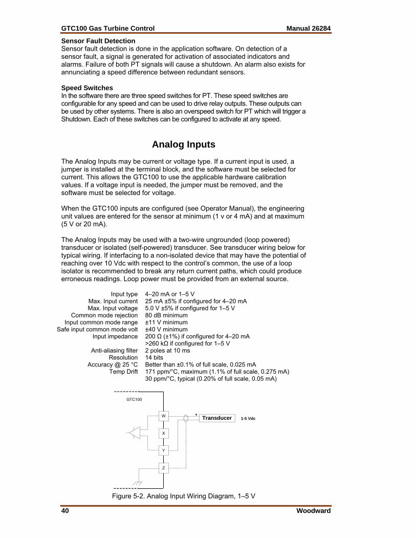
GTC100 Gas Turbine Control Manual 26284
40 Woodward
Sensor Fault Detection Sensor fault detection is done in the application software. On detection of a sensor fault, a signal is generated for activation of associated indicators and alarms. Failure of both PT signals will cause a shutdown. An alarm also exists for annunciating a speed difference between redundant sensors. Speed Switches In the software there are three speed switches for PT. These speed switches are configurable for any speed and can be used to drive relay outputs. These outputs can be used by other systems. There is also an overspeed switch for PT which will trigger a Shutdown. Each of these switches can be configured to activate at any speed.
Analog Inputs The Analog Inputs may be current or voltage type. If a current input is used, a jumper is installed at the terminal block, and the software must be selected for current. This allows the GTC100 to use the applicable hardware calibration values. If a voltage input is needed, the jumper must be removed, and the software must be selected for voltage. When the GTC100 inputs are configured (see Operator Manual), the engineering unit values are entered for the sensor at minimum (1 v or 4 mA) and at maximum (5 V or 20 mA). The Analog Inputs may be used with a two-wire ungrounded (loop powered) transducer or isolated (self-powered) transducer. See transducer wiring below for typical wiring. If interfacing to a non-isolated device that may have the potential of reaching over 10 Vdc with respect to the control’s common, the use of a loop isolator is recommended to break any return current paths, which could produce erroneous readings. Loop power must be provided from an external source.
Input type 4–20 mA or 1–5 V Max. Input current 25 mA ±5% if configured for 4–20 mA Max. Input voltage 5.0 V ±5% if configured for 1–5 V
Common mode rejection 80 dB minimum Input common mode range ±11 V minimum
Safe input common mode volt ±40 V minimum Input impedance 200 Ω (±1%) if configured for 4–20 mA
>260 kΩ if configured for 1–5 V Anti-aliasing filter 2 poles at 10 ms
Resolution 14 bits Accuracy @ 25 °C Better than ±0.1% of full scale, 0.025 mA
Temp Drift 171 ppm/°C, maximum (1.1% of full scale, 0.275 mA) 30 ppm/°C, typical (0.20% of full scale, 0.05 mA)
GTC100
W
X
Y
Z
Transducer+1-5 Vdc
Figure 5-2. Analog Input Wiring Diagram, 1–5 V
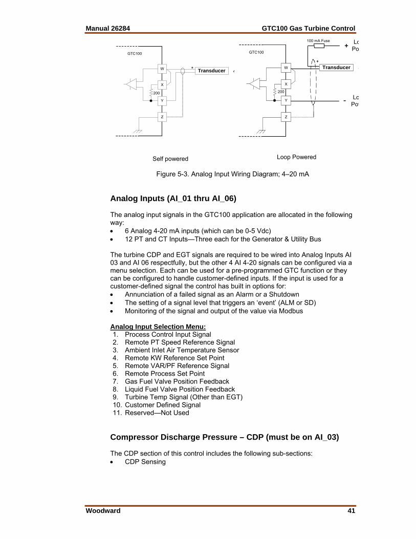
Manual 26284 GTC100 Gas Turbine Control
Woodward 41
GTC100
W
X
Y
Z
Transducer+4
200
Self powered
GTC100
W
X
Y
Z
+Transducer 4
+
-
LoPo
LoPow
100 mA Fuse
200
Loop Powered
Figure 5-3. Analog Input Wiring Diagram; 4–20 mA Analog Inputs (AI_01 thru AI_06) The analog input signals in the GTC100 application are allocated in the following way: • 6 Analog 4-20 mA inputs (which can be 0-5 Vdc) • 12 PT and CT Inputs—Three each for the Generator & Utility Bus The turbine CDP and EGT signals are required to be wired into Analog Inputs AI 03 and AI 06 respectfully, but the other 4 AI 4-20 signals can be configured via a menu selection. Each can be used for a pre-programmed GTC function or they can be configured to handle customer-defined inputs. If the input is used for a customer-defined signal the control has built in options for: • Annunciation of a failed signal as an Alarm or a Shutdown • The setting of a signal level that triggers an ‘event’ (ALM or SD) • Monitoring of the signal and output of the value via Modbus Analog Input Selection Menu: 1. Process Control Input Signal 2. Remote PT Speed Reference Signal 3. Ambient Inlet Air Temperature Sensor 4. Remote KW Reference Set Point 5. Remote VAR/PF Reference Signal 6. Remote Process Set Point 7. Gas Fuel Valve Position Feedback 8. Liquid Fuel Valve Position Feedback 9. Turbine Temp Signal (Other than EGT) 10. Customer Defined Signal 11. Reserved—Not Used
Compressor Discharge Pressure – CDP (must be on AI_03) The CDP section of this control includes the following sub-sections: • CDP Sensing
GTC100 Gas Turbine Control Manual 26284
42 Woodward
CDP Sensing The compressor discharge pressure (CDP) is sensed by a 4-to-20 mA pressure transducer. This value is then used by the control for pressure control and fuel schedules. This must be used unless the fuel valve system includes CDP acceleration limiting (some valves and on-engine fuel systems do this). Exhaust Gas Temperature – EGT (must be on AI_06) The EGT section of this control includes the following sub-sections: • EGT Sensing • Temperature Reference • Temperature Switch Output Relay Signals EGT Sensing This input is programmed to receive a single 4–20 mA input that senses the EGT. The system feeds the temperature information from this signal to the three temperature switches, the overtemp switch, and the EGT control PID. Temperature Reference The EGT Reference is set by a tunable variable and can be configured to use an ambient temperature bias. There is an option to use the EGT control for starting the unit. Temperature Switches In the software there are three temperature switches for the EGT. These temp switches are configurable for any temperature set point and can used to drive relay outputs. These outputs can be used by other systems.
Optional Analog Input Signals Programmed Process Control Input Sensor – (Option #1) The process input signal is available for applications that plan to use the turbine load capability to control a plant determined parameter. The control can be setup to control this value to a programmed set point. The GTC will then use this output to determine the turbine load set point. Remote PT Speed Reference - (Option #2) The speed reference produces the desired speed-setting signal and sends it to the speed controller. The sub-functions are: • Speed Setting • Remote Speed Setting (PT only) Speed Setting The PT speed setting is raised or lowered by closing the associated contact or by commands through the Modbus communication link. The rate at which the reference changes can also be selected. The speed reference has both an upper and a lower limit position. The speed setting at each of these positions is a tunable value. The speed reference also includes relay options to indicate when that speed reference is at the lower limit.

Manual 26284 GTC100 Gas Turbine Control
Woodward 43
Remote Speed Setting The PT speed setting can be controlled by a remote signal. The ENABLE contact enables remote speed setting, as long as the speed is above rated speed. When enabled, the speed setting can be changed by varying a remote 4-to-20 mA signal. At this time all PT associated switch contacts (RAISE, LOWER, FAST, and INSTANT) will be disabled. Ambient or Compressor Inlet Temperature Sensor - (Option #3) The control is designed to receive an ambient temperature signal or a compressore inlet signal via a single 4–20 mA input, a thermocouple input, or via an RTD input. It is very common for this ambient temperature to be sensed by an AD590. There is an optional kit item that can be included with the GTC products to convert this signal. The AD590 microamp signal is converted to a milliamp signal through the Moore Industries device. This device has been programmed with a microamp to milliamp/temperature conversion chart that converts the value into a 4–20 mA signal. The ambient temperature sensor signal is converted to a digital signal in the AtlasSC Digital Control System and can be configured to bias the EGT temperature reference and the Acceleration limiter curve. If the ambient temperature input signal fails, a fixed-value signal (tunable) is used as the bias signal. Remote KW Reference - (Option #4) A remote KW reference set point can be brought back into the control via a 4-to-20 mA signal. This value is used as the set point for the KW Load controller. Remote VAR/PF Reference - (Option #5) For units that include the PowerSense module, a remote VAR or PF reference set point can be brought back into the control via a 4-to-20 mA signal. This value is used as the set point for the Reactive Load controller. Remote Process Reference Set Point - (Option #6) A remote Process reference set point can be brought back into the control via a 4-to-20 mA signal. This value is used as the set point for the Process controller. Gas Fuel Valve Position Feedback - (Option #7) The gas fuel valve position feedback can be brought back into the control via a 4-to-20 mA signal from the valve driver or the valve itself. This value is sent to the Modbus communication link for display purposes. Liquid Fuel Valve Position Feedback - (Option #8) The liquid fuel valve position feedback can be brought back into the control via a 4-to-20 mA signal from the valve driver or the valve itself. This value is sent to the Modbus communication link for display purposes.
GTC100 Gas Turbine Control Manual 26284
44 Woodward
Turbine Temperature Signal (other than EGT) - (Option #9) This option is designed for use with some turbines that utilize a turbine temperature signal which is located close to the combustor. The GTC application is designed to allow this signal to be used as an alternate temperature control signal (instead of the EGT signal). EGT is still used as an overtemperature protection signal. This input can be used as the process signal for the temperature control PID, the start overtemp trip level, and the running overtemp trip level. Customer Defined Signal - (Option #10) The customer can bring in a 4–20 mA signal for any desired site-specific parameter. The GTC application is designed to allow a configurable switch to be activated by this input value. This event action can be configured as an Alarm or a Shutdown. The user can configure the loss of this input signal to trigger either an Alarm or a Shutdown.
Discrete Inputs There are 24 discrete inputs which are all individually optically isolated; however, all 24 share a common power supply return. The inputs expect 24 Vdc for an asserted state.
Number of channels 24 Input type Optically isolated discrete input
Input thresholds < 8 Vdc = “OFF” > 16 Vdc = “ON”
Input current 3 mA @ 24 Vdc Contact voltage 24 Vdc isolated
Max input voltage 28 Vdc Isolation voltage 500 Vac, all channels are isolated from the other I/O
An external 18–28 Vdc power source can be used to source the circuit wetting voltage for the discrete inputs. Due to circuit isolation, the external power supply common must be connected to the GTC100 terminal 25 as shown in the wiring diagrams in Appendix A. However, for EMC Compliance, the on board, isolated, +24 Vdc supply is recommended for use as the contact wetting voltage. The internal supply should only be used for the discrete inputs as shown in the diagrams; use in other, unrelated, circuits could overload the supply or create ground loops. The internal, isolated, supply is limited to approximately 300 mA maximum. Discrete Inputs (BI_01 thru BI_24) These twenty-four discrete inputs are available as direct inputs into the AtlasSC I/O. These ‘high-speed’ input signals are used to direct the actions and functions of the fuel control. The first 3 inputs are fixed and can only be used for the function shown. All other inputs (4-24) are configurable to be used for the function shown or to be used for custom signals. If the discrete inputs is used for a custom signal, the have been pre-programmed with the following optional functionality: • A Start Permissive Input • An Alarm Condition Input • An Shutdown Condition Input
Manual 26284 GTC100 Gas Turbine Control
Woodward 45
The default function and active state of each of these signals are shown, any of these can be altered in the configuration of the control. The signal status of each input will be sent through the Modbus communication link as indications.
SPECIAL NOTE ON BI-20 AND BI-24 These two inputs can also have a delay (0–30 s) and a speed switch enable/disable function added to them. They are connected to Speed Switch #1, and the action (disable or enable above this speed) can be set in DEBUG mode by tuning CNFG_BI_xx.OVR_EVENT.CTRL. For example, a low lube pressure trip input that is sensing lube oil pressure produced by the turbine accessory gearbox may need to be disabled until a certain speed is achieved.
GTC Function Active State 1. Shutdown (Fuel Off) * TRUE = Shutdown / Fuel OFF 2. Start/Run (ON to Run) * TRUE = Start / Fuel ON, (False = Normal Stop) 3. System Reset (ALM & SD) * TRUE = Reset Alarm/Shutdown 4. System Acknowledge (ALM & SD) TRUE = Acknowledge Alarm/Shutdown 5. PT Reference Lower TRUE = Lower PT Speed Set Point 6. PT Reference Raise TRUE = Raises PT Speed Set Point 7. PT Reference Select Fast Rate TRUE = PT Speed Set Point Rate = Fast 8. PT Speed Signal Failed Override TRUE = Override PT sensor failure (to Start) 9. Set Ref to Rated Speed / Go Baseload TRUE = if GEN Breaker is Open then PT Ref
= Rated Speed / if GEN Breaker is Closed then Enable Baseload Control
10. Combustor Flame Detector TRUE = Flame Detected 11. Fuel Selection/Transfer TRUE = Liquid Fuel (False = Gas Fuel) 12. Enable Remote PT Reference Set Point TRUE = Actively follow remote set point 13. Inhibit Synchronizer TRUE = Disable Synchronization logic 14. Generator Breaker Aux (52) TRUE = Generator Breaker Open (Isoch) 15. Utility Breaker Open TRUE = Utility Breaker Open (Permissive for LS) 16. Enable Reactive Load Control TRUE = Enables unit VAR/PF Control 17. Voltage/VAR/PF Lower Command TRUE = Lower the Reactive Load set point 18. Voltage/VAR/PF Raise Command TRUE = Raise the Reactive Load set point 19. Enable Process Control TRUE = Enable Process Control 20. Process Set Point Lower Command TRUE = Lower the Process set point 21. Process Set Point Raise Command TRUE = Raise the Process set point 22. Gas Fuel Valve/Actuator Fault TRUE = Gas Fuel Valve/Actuator Fault 23. Liquid Fuel Valve/Actuator Fault TRUE = Liquid Fuel Valve/Actuator Fault 24. Select EGT Peak Setpoint TRUE = Use Peak Setpoint
Discrete Outputs There are 12 discrete output relay drivers, which are individually optically isolated, available from the AtlasSC I/O. However, all twelve share a common power supply and return circuit. Each output uses a thermally protected MOSFET that will pulse the circuit if the current limit is exceeded. An over-current condition on one output will not affect the other outputs. The output will be pulsed continuously until the current requirement is reduced, allowing the output to operate normally again.
Number of channels 12 Output type Low-side driver with short circuit and over voltage
protection Current drive rating <200 mA
Discrete Output supply voltage 9-32 Vdc Isolation voltage 500 Vac, all channels are isolated from the other I/O
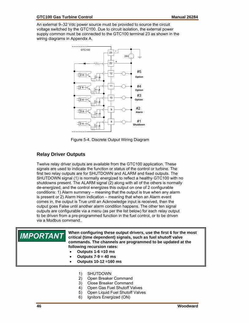
GTC100 Gas Turbine Control Manual 26284
46 Woodward
An external 9–32 Vdc power source must be provided to source the circuit voltage switched by the GTC100. Due to circuit isolation, the external power supply common must be connected to the GTC100 terminal 23 as shown in the wiring diagrams in Appendix A.
GTC100
12
11
10
8
23
22
24V
+
-
#5
#4
#3
#2
#1
Alarm
Option
Shutdown
Option
Option
9
Figure 5-4. Discrete Output Wiring Diagram Relay Driver Outputs Twelve relay driver outputs are available from the GTC100 application. These signals are used to indicate the function or status of the control or turbine. The first two relay outputs are for SHUTDOWN and ALARM and fixed outputs. The SHUTDOWN signal (1) is normally energized to reflect a healthy GTC100 with no shutdowns present. The ALARM signal (2) along with all of the others is normally de-energized, and the control energizes this output on one of 2 configurable conditions: 1) Alarm summary – meaning that the output is true when any alarm is present or 2) Alarm Horn indication – meaning that when an Alarm event comes in, the output is True until an Acknowledge input is received, then the output goes False until another alarm condition happens. The other ten signal outputs are configurable via a menu (as per the list below) for each relay output to be driven from a pre-programmed function in the fuel control, or to be driven via a Modbus command..
When configuring these output drivers, use the first 6 for the most critical (time dependent) signals, such as fuel shutoff valve commands. The channels are programmed to be updated at the following recursion rates: • Outputs 1-6 =10 ms • Outputs 7-9 = 40 ms • Outputs 10-12 =160 ms
1) SHUTDOWN 2) Open Breaker Command 3) Close Breaker Command 4) Open Gas Fuel Shutoff Valves 5) Open Liquid Fuel Shutoff Valves 6) Ignitors Energized (ON)

Manual 26284 GTC100 Gas Turbine Control
Woodward 47
7) Motor Starter Engaged 8) ALARM 9) PT Speed Switch 1 10) PT Speed Switch 2 11) PT Speed Switch 3 12) Run/Reset Output to Fuel Valve 13) PT Speed Reference at Lower Limit 14) GTC Health Indication (Fuel Control ON) 15) Running on Liquid Fuel (off = On Gas Fuel) 16) Raise Voltage Command to AVR 17) Lower Voltage Command to AVR 18) Speed in Control 19) EGT in Control 20) CDP in Control 21) Process Control Enabled 22) Remote PT Speed Reference Enabled 23) Load Sharing Enabled 24) Max Turbine Output Load Reached 25) EGT Temp Switch 1 26) EGT Temp Switch 2 27) EGT Temp Switch 3 28) Customer Command from Modbus BW 21 29) Customer Command from Modbus BW 22 30) Customer Command from Modbus BW 23 31) Customer Command from Modbus BW 24 32) Transferring Fuels
Actuator Driver Outputs (ACT_01 and ACT_02) This system includes two actuator drivers, one for the gaseous-fuel actuator (ACT_01) and one for the liquid-fuel actuator (ACT_02). Each of the actuator drivers receives a fuel demand signal and sends a proportional drive current signal to its actuator. Each actuator, in turn, controls the flow of one type of fuel. The outputs are configurable as 4–20 mA or 0–200 mA. These outputs are proportional drivers only—if integrating drivers are required, inquire about the Woodward Servo Position Controller (SPC).
Number of channels 2 Actuator Type Proportional, non-isolated
Output type 4–20 or 20-160 mA outputs, software selectable Common Mode Voltage 15 Vdc ±10%
Max current output 25 mA ±5% (4-20 mA scale) 200 mA ±5% (20-160 mA scale)
Min. load resistance 0 Ω Max load resistance 300 Ω at 22 mA (4-20 mA scale)
45 Ω at 200 mA (20-160 mA scale) Resolution 12 bits
Accuracy @ 25 °C Better than ±0.1% of full scale 0.026mA (4-20 mA scale) 0.2mA (20-160 mA scale)
Readback Accuracy @ 25 °C 0.5% Temperature Drift 140 ppm/°C,
0.24 mA maximum (4-20 mA scale) 1.82 mA maximum (20-160 mA scale) 70 ppm/°C, typical (0.45% of full scale, 0.11375 mA) 0.12 mA maximum (4-20 mA scale) 0.91 mA maximum (20-160 mA scale)
Readbacks Actuator source and return currents Dither Current 25 Hz, fixed duty cycle, software variable amplitude

GTC100 Gas Turbine Control Manual 26284
48 Woodward
GTC100
X
Y
Z
+
Output mA
+15 Vdc
A
Figure 5-5. Actuator Output Wiring Diagram Gas Fuel Valve Position Demand (ACT_01) The gas fuel valve position demand is output from the control via this actuator output channel. It can be a 4-20 mA or 20-160 mA signal from the control to the valve driver or to the valve itself. Liquid Fuel Valve Position Demand (ACT_02) The liquid fuel valve position demand is output from the control via this actuator output channel. It can be a 4-20 mA or 20-160 mA signal from the control to the valve driver or to the valve itself.
Analog Outputs There are six analog outputs that may be assigned to a number of functions. Each output is a 4–20 mA current source. The Analog Outputs may be used with a two-wire ungrounded device or isolated device. If interfacing to a non-isolated device, the use of a loop isolator is required. The chart below give the parameters that may be configured for analog output, The scale or range of each parameter can also be changed, i.e. a frequency read out may be set for 57 to 63 Hz, or 30 to 65 Hz.
Number of channels 6, PWM outputs Output type 4–20 mA outputs, non-isolated
PWM frequency 1.5 kHz Common Mode Voltage 15 Vdc ±10%
Current output 4–20 mA Max current output 25 mA ±5%
Min. load resistance 0 Ω Max load resistance 300 Ω at 22 mA
Resolution 12 bits Accuracy @ 25 °C Better than ±0.1% of full scale, 0.025 mA Temperature Drift 140 ppm/°C, 0.23 mA maximum
70 ppm/°C, typical (0.45% of full scale, 0.11375 mA) Each analog output has identical circuitry. There is no isolation between outputs and no isolation to the digital circuitry of the GTC100. Wiring for each is shown below but only the terminal numbers change for each output.

Manual 26284 GTC100 Gas Turbine Control
Woodward 49
GTC100
X
Y
Z
+
4-20 mA
+15 Vdc
A
Figure 5-6. Analog Output Wiring Diagram Analog Outputs (AO_01 thru AO_06) The system includes six analog outputs. These readout signals are 4–20 mA signals for driving meters or sending readouts to other plant system controls. Each of these signals is configurable in the application program. The default status for each one is to be driven by the fuel control with the functions shown below in selection numbers 1-6 respectively. 1. PT Actual Speed Readout 2. PT Reference Speed Readout 3. Fuel Valve Demand Readout 4. Exhaust Gas Temperature Readout 5. Compressor Discharge Pressure Readout 6. Generator MW Sensor Readout 7. Generator MegaVar Output Readout 8. Generator MegaVoltAmp Output Readout 9. Generator Power Factor Output Readout 10. Generator Current 11. Generator Voltage 12. Utility Bus MW Sensor Readout 13. Utility Bus MegaVar Output Readout 14. Utility Bus MegaVoltAmp Output Readout 15. Utility Bus Power Factor Output Readout 16. Utility Bus Current 17. Utility Bus Voltage 18. Synchroscope Output 19. Customer Configurable Analog Output (from Modbus AW_11) 20. Customer Configurable Analog Output (from Modbus AW_12) 21. Customer Configurable Analog Output (from Modbus AW_13)
*Via the Watch Window service tool it is possible to select the output of the power monitoring elements to be displayed as a phase value, or total/average of the phases. The default is to output the total/average.
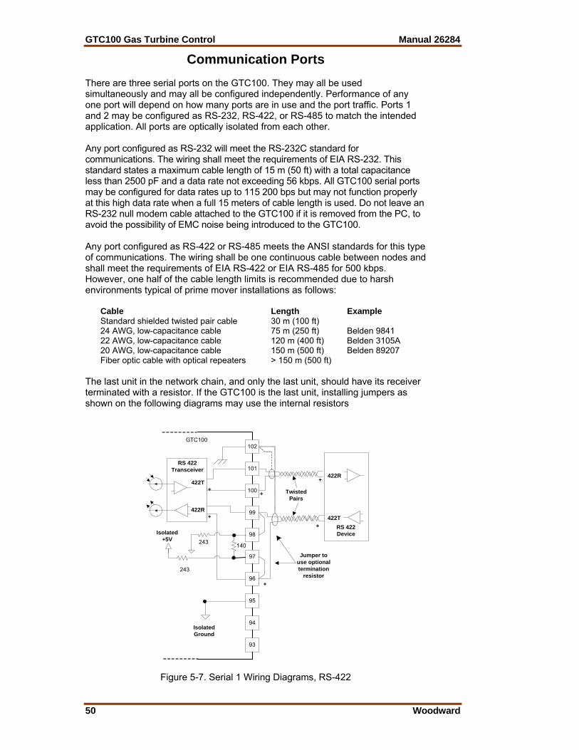
GTC100 Gas Turbine Control Manual 26284
50 Woodward
Communication Ports There are three serial ports on the GTC100. They may all be used simultaneously and may all be configured independently. Performance of any one port will depend on how many ports are in use and the port traffic. Ports 1 and 2 may be configured as RS-232, RS-422, or RS-485 to match the intended application. All ports are optically isolated from each other. Any port configured as RS-232 will meet the RS-232C standard for communications. The wiring shall meet the requirements of EIA RS-232. This standard states a maximum cable length of 15 m (50 ft) with a total capacitance less than 2500 pF and a data rate not exceeding 56 kbps. All GTC100 serial ports may be configured for data rates up to 115 200 bps but may not function properly at this high data rate when a full 15 meters of cable length is used. Do not leave an RS-232 null modem cable attached to the GTC100 if it is removed from the PC, to avoid the possibility of EMC noise being introduced to the GTC100. Any port configured as RS-422 or RS-485 meets the ANSI standards for this type of communications. The wiring shall be one continuous cable between nodes and shall meet the requirements of EIA RS-422 or EIA RS-485 for 500 kbps. However, one half of the cable length limits is recommended due to harsh environments typical of prime mover installations as follows:
Cable Length ExampleStandard shielded twisted pair cable 30 m (100 ft) 24 AWG, low-capacitance cable 75 m (250 ft) Belden 9841 22 AWG, low-capacitance cable 120 m (400 ft) Belden 3105A 20 AWG, low-capacitance cable 150 m (500 ft) Belden 89207 Fiber optic cable with optical repeaters > 150 m (500 ft)
The last unit in the network chain, and only the last unit, should have its receiver terminated with a resistor. If the GTC100 is the last unit, installing jumpers as shown on the following diagrams may use the internal resistors
+
GTC100
100
99
98
97
96
102
101
95
94
RS 422Transceiver
422T
422R
93
140
+
IsolatedGround
RS 422Device
422T
422R
+
+
TwistedPairs
Jumper touse optionaltermination
resistor
Isolated+5V 243
+
+
243
Figure 5-7. Serial 1 Wiring Diagrams, RS-422
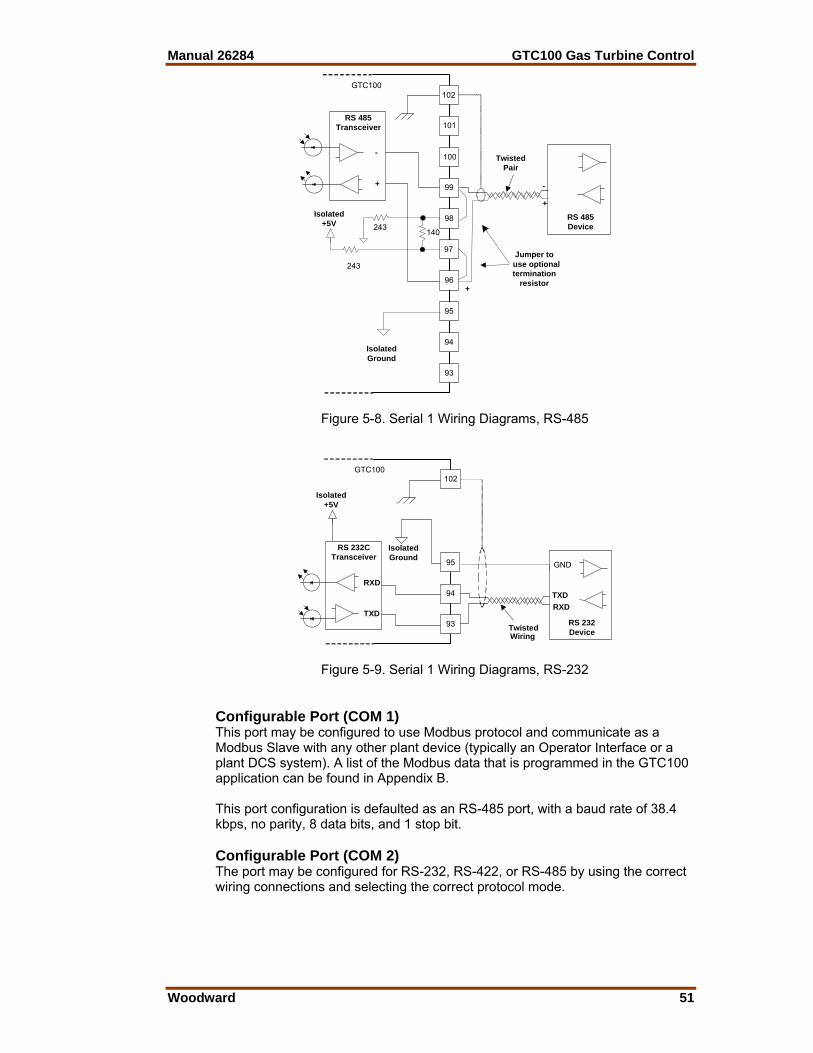
Manual 26284 GTC100 Gas Turbine Control
Woodward 51
GTC100
100
99
98
97
96
102
101
95
94
RS 485Transceiver
-
+
93
IsolatedGround
RS 485Device
-
+
TwistedPair
+
140
Isolated+5V 243
243 use optionalJumper to
terminationresistor
Figure 5-8. Serial 1 Wiring Diagrams, RS-485
GTC100102
95
94
93
IsolatedGround
RS 232DeviceTwisted
Wiring
Isolated+5V
RS 232CTransceiver
RXD
TXDRXDTXD
GND
Figure 5-9. Serial 1 Wiring Diagrams, RS-232 Configurable Port (COM 1) This port may be configured to use Modbus protocol and communicate as a Modbus Slave with any other plant device (typically an Operator Interface or a plant DCS system). A list of the Modbus data that is programmed in the GTC100 application can be found in Appendix B. This port configuration is defaulted as an RS-485 port, with a baud rate of 38.4 kbps, no parity, 8 data bits, and 1 stop bit. Configurable Port (COM 2) The port may be configured for RS-232, RS-422, or RS-485 by using the correct wiring connections and selecting the correct protocol mode.
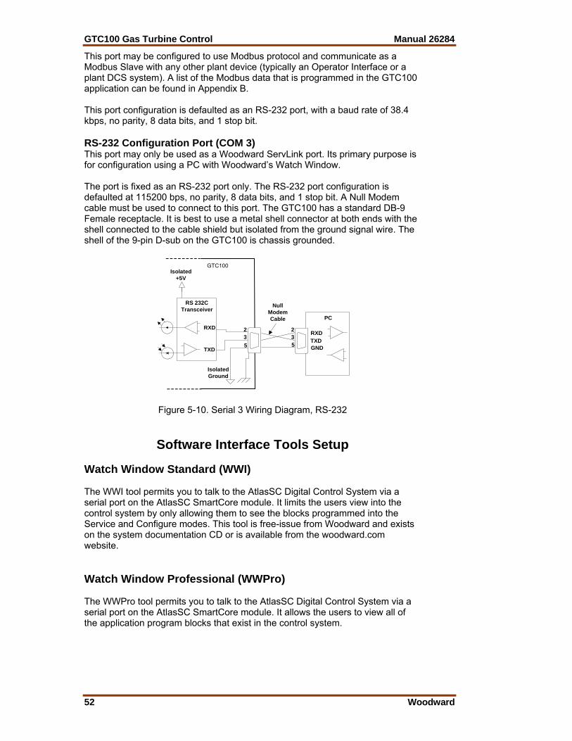
GTC100 Gas Turbine Control Manual 26284
52 Woodward
This port may be configured to use Modbus protocol and communicate as a Modbus Slave with any other plant device (typically an Operator Interface or a plant DCS system). A list of the Modbus data that is programmed in the GTC100 application can be found in Appendix B. This port configuration is defaulted as an RS-232 port, with a baud rate of 38.4 kbps, no parity, 8 data bits, and 1 stop bit. RS-232 Configuration Port (COM 3) This port may only be used as a Woodward ServLink port. Its primary purpose is for configuration using a PC with Woodward’s Watch Window. The port is fixed as an RS-232 port only. The RS-232 port configuration is defaulted at 115200 bps, no parity, 8 data bits, and 1 stop bit. A Null Modem cable must be used to connect to this port. The GTC100 has a standard DB-9 Female receptacle. It is best to use a metal shell connector at both ends with the shell connected to the cable shield but isolated from the ground signal wire. The shell of the 9-pin D-sub on the GTC100 is chassis grounded.
GTC100
IsolatedGround
Isolated+5V
RS 232CTransceiver
RXD
TXD
235
PC
RXDTXDGND
235
NullModemCable
Figure 5-10. Serial 3 Wiring Diagram, RS-232
Software Interface Tools Setup Watch Window Standard (WWI) The WWI tool permits you to talk to the AtlasSC Digital Control System via a serial port on the AtlasSC SmartCore module. It limits the users view into the control system by only allowing them to see the blocks programmed into the Service and Configure modes. This tool is free-issue from Woodward and exists on the system documentation CD or is available from the woodward.com website. Watch Window Professional (WWPro) The WWPro tool permits you to talk to the AtlasSC Digital Control System via a serial port on the AtlasSC SmartCore module. It allows the users to view all of the application program blocks that exist in the control system.

Manual 26284 GTC100 Gas Turbine Control
Woodward 53
Watch Window Program (Both Standard and Professional) Use of one of the WW tools (Standard or Professional) is required to access the application software tunable values of the AtlasSC Digital Control System. Software setup for the GTC100 begins with the Software Configuration & Service Tunables Worksheet. When the worksheet is completed, the values are then entered into the GTC100 with the WW tool. This tool can also be used to upload (from the control to a file on the user PC) the tunable settings from the control. This file then can be downloaded (from the user PC to the control) into another control of the same part number and revision number. Keep this tunable file archived, as it will simplify configuration of other spare units and aid technical support in commissioning and troubleshooting. WWI runs on a PC connected to the control system through a serial communications port. The PC may be permanently connected to the control or connected only as needed. The communications server, ServLink I/O Server, is included in the same CD-ROM with the Watch Window software. An “inspector” provides a window for real-time monitoring and editing of all control Configuration and Service Menu parameters and values. Custom “inspectors” can easily be created and saved (WWPro only). Each window can display up to 28 lines of monitoring and tuning parameters without scrolling. The number with scrolling is unlimited. Two windows can be open simultaneously to display up to 56 parameters without scrolling. Tunable values can be adjusted at the inspector window. Watch Window communicates with the control through an RS-232 cable connection to the comm port configured as a point-to-point only ServLink Server. Watch Window is a typical Windows application that provides a powerful and intuitive interface. The menu structures are familiar to Windows users. Variable navigation is provided through the Explorer window similar to the Explorer in Windows. Watch Window performs these primary functions: Monitoring and Tuning of Control Variables—Watch Window presents variables in a tabular format. The user chooses the variables to view. Multiple pages of variables can be created, each with useful parameters for various troubleshooting or tuning procedures. The user can toggle between pages depending on the task being performed. Control Configuration and Set Point Management—Watch Window can upload or download all tunable variables from the control system. This feature allows a user (e.g., fleet owner, distributor, packager) to upload (and save) all tunable parameters from one control and download the same settings to other controls for similar turbine configurations.
Watch Window version 1.05 and higher, allows for automatic generation of inspector sheets. Click on the Q icon (Quick Inspector) on the tool bar. A sheet will automatically be created from each Service and Configure Header programmed into the control. Multiple inspectors can be created to allow for viewing more than one sheet at a time.

GTC100 Gas Turbine Control Manual 26284
54 Woodward
To enter the I/O Lock mode and enable a configure value to be entered, click on the I/O Lock icon on the Tool Bar. Because the values set in Configure are critical to turbine operation, it is not safe to operate the prime mover while these parameters are being configured. In the Configure mode, the control outputs will be set to their off state and the microprocessor will stop executing the application code. The control will have to be reset to continue operation.
The Reset icon allows the microprocessor to store the configure parameters, to return the outputs to their active state, and to resume executing the application software.
When the tuning or setting of parameters is complete, the values must be saved in the control’s non-volatile memory. Go to the Tool Bar and click the PROM icon for Save Values. The values will be saved in non-volatile memory and will be unaffected by loss of power to the control.
If an application configuration has been previously saved to a *.CFG file, the saved set of parameters can be loaded into the control as a group by selecting the Load Application Settings icon.
To save the configuration to a file in the external computer for backup or download later into another control, select the Save Application Settings icon. All the tunable values presently set in the control will be saved to a file and can be loaded into this control to reprogram it to the saved values or into another control at a later time. Install Watch Window Software Woodward’s Watch Window Standard configuration and service tool may be downloaded at no cost from the Woodward website (www.woodward.com/software). As an alternative, a Watch Window CD Install Kit may be purchased from the nearest Woodward distributor. Once downloaded, select the kit’s Setup.exe program on the computer on which you wish to install the Watch Window software program. Please refer the product specification 03202 for detailed installation procedures. Connect PC to GTC100 The connection of a computer is only required for calibration and setup of the GTC100. The computer and WWI software program are not required or necessary for normal operation of the control. You will need to connect a standard 9-pin Null Modem cable between the communication port # 3 (COM 3) of the AtlasSC Main (SmartCore) module on the GTC100 and a user PC. This port has a 9-pin sub-D connector and is located on the bottom layer of the PC104 bus stack of the control modules. This port’s protocol settings are defaulted to the correct settings to communicate with the Woodward WWI service tool (Baud = 115200, Data Bits = 8, Stop Bits = 1, Parity = None). For information on the cable or communication port settings, see the troubleshooting section of this manual.
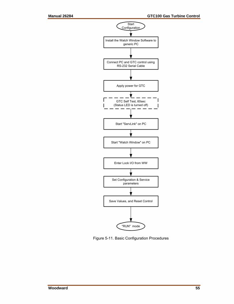
Manual 26284 GTC100 Gas Turbine Control
Woodward 55
Install the Watch Window Software togeneric PC
Connect PC and GTC control usingRS-232 Serial Cable
Apply power for GTC
GTC Self Test, 60sec(Status LED is turned off)
Start "ServLink" on PC
Start "Watch Window" on PC
Enter Lock I/O from WW
Set Configuration & Serviceparameters
Save Values, and Reset Control
"RUN" mode
StartConfiguration
Figure 5-11. Basic Configuration Procedures

GTC100 Gas Turbine Control Manual 26284
56 Woodward
Apply Power to the GTC100 At power-up, the GTC100 runs through its boot-up routine and performs a set of initial diagnostics to verify CPU, memory, I/O initialization, and bus health. This boot-up routine takes approximately a minute to execute. During this time, the control’s red status LEDs on the CPU and I/O modules should be on. When boot-up is complete, the application program code begins running, the control outputs will be enabled, and system control will begin—the control’s red status LEDs will turn off and should remain off as long as the control is running. Initial GTC100 Communications: Before communications can begin between the WWI program and a control, a network definition file must be created. Once this network definition file is created and saved, it never has to be recreated, unless a new program is loaded into the control. To create a network definition file: 1. Open the Watch Window program’s associated ServLink server by clicking
on Start > Programs > Woodward > ServLink Server.exe. 2. Select the communications port the control is connected to. 3. Select “Point-to-Point” communications. 4. Select the Baud Rate of 115200. 5. Select the OK button.
Figure 5-12. Setup ServLink Communication
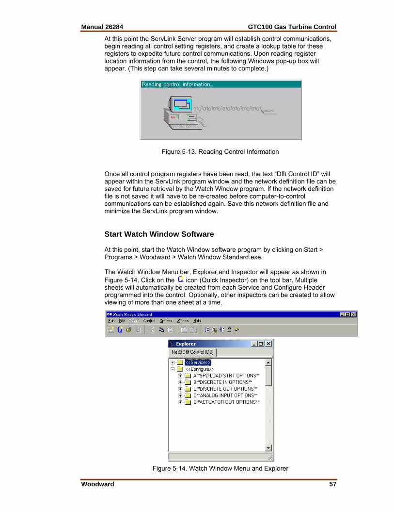
Manual 26284 GTC100 Gas Turbine Control
Woodward 57
At this point the ServLink Server program will establish control communications, begin reading all control setting registers, and create a lookup table for these registers to expedite future control communications. Upon reading register location information from the control, the following Windows pop-up box will appear. (This step can take several minutes to complete.)
Figure 5-13. Reading Control Information Once all control program registers have been read, the text “Dflt Control ID” will appear within the ServLink program window and the network definition file can be saved for future retrieval by the Watch Window program. If the network definition file is not saved it will have to be re-created before computer-to-control communications can be established again. Save this network definition file and minimize the ServLink program window. Start Watch Window Software At this point, start the Watch Window software program by clicking on Start > Programs > Woodward > Watch Window Standard.exe. The Watch Window Menu bar, Explorer and Inspector will appear as shown in Figure 5-14. Click on the icon (Quick Inspector) on the tool bar. Multiple sheets will automatically be created from each Service and Configure Header programmed into the control. Optionally, other inspectors can be created to allow viewing of more than one sheet at a time.
Figure 5-14. Watch Window Menu and Explorer

GTC100 Gas Turbine Control Manual 26284
58 Woodward
Configure Menu Descriptions The GTC100 has multiple Configure and Service menus to simplify and protect control settings and their adjustments. All menus appear as pages (or sheets), are arranged alphabetically, and can be located by using the inspector’s arrow buttons located above the pages to scroll to the desired menu. The program’s Configure menu items are protected when the control is in operation and cannot be changed. Before configuration values can be changed, the control must be in its I/O Lock mode. Service menus are not protected and can be modified at any time. To enter the I/O Lock mode and enable configure changes, click on the I/O Lock icon on the Tool Bar. Because the values set in Configure are critical to turbine operation, it is not safe to operate the prime mover while these parameters are being configured. In the I/O Lock mode the control outputs will be set to their off state and the microprocessor will stop executing the application code. Once the configuration changes have been completed click on the Reset icon to allow the control to store the configured parameters, return the outputs to their active state and resume executing the application software. Control Assistant Software This tool is an optional utility program that can help manage tunable values and trend values within the control. It can be a useful troubleshooting tool for experienced users. The control has the option of having Port # 2 allocated for use as a control assistant port. If needed this port can be temporarily tuned for interface to control assistant and then later tuned back to communicate Modbus data to another device. The latest version of this software (not released at the time of this manual being published) can also be used as the main service interface tool, on COM port # 3. It is a purchased product that includes trending capability, tunable maintenance tools, and built-in Watch Window Professional functionality.
Manual 26284 GTC100 Gas Turbine Control
Woodward 59
Chapter 6. Configuration and Service Setup
Procedures
Introduction This chapter contains information on control configurations, setting adjustments, and the use of Woodward’s Watch Window software tool. Because of the variety of installations, system and component tolerances, the GTC100 must be tuned and configured for each system to obtain safe operation and optimum performance.
An improperly calibrated control could cause an overspeed or other damage to the prime mover. To prevent possible serious injury from an overspeeding prime mover, read this entire procedure before starting the prime mover.
The worksheet in the Appendices of this manual should be used to select the values used in the tunable blocks of the GAP™ program for the GTC100 application. On the lines provided, enter the values used for your control. Once the worksheet is completed, connect the control with the WWI tool as described in the previous section. Click on the Q in the tool bar to execute a routine that will automatically generate an inspector file for all of the configuration and service fields (you will want to resize the Block, Field, and Value columns in the inspector file to see the complete prompts that exist for each row). Using the worksheet, tune each field to the value you require for your application. Use a separate worksheet for each control when more than one control is used at each site. Note that as a user gets more familiar with the system, you can modify/customize your own inspector files to best fit your needs. This should be done at initial installation to establish the correct turbine package configuration details for correct operation of the fuel control. The turbine must be shutdown (in a non-running state) during control set-up to tune or adjust any of the parameters on the Configuration sheets. This is not required to adjust or tune any parameters in the Service sheets.
Start Modes This control contains options for start control, which is the initial control mode for the fuel. These options are intended to provide a consistent acceleration of the turbine, from turbine ‘lite-off’ up to closed loop speed control. Once the fuel control has reached speed control, the start mode demand signal is ramped out of the way (to 100%). It is important to point out that the fuel control will not ramp the fuel valve open until the control recognizes that the turbine has achieved ‘lite-off’. The default start option is to have the control raise the fuel demand via a start ramp at the user-defined rate until the unit reaches PT Speed control at the minimum PT reference value. This allows for the most aggressive ramp-up times of the turbine. For less aggressive ramp-ups, the start ramp rate can be reduced, or the EGT Temp controlled start ramp option can be enabled.
GTC100 Gas Turbine Control Manual 26284
60 Woodward
Once the Start / Run discrete input contact is closed (TRUE), the fuel control will initiate a start. If the GTC Start Sequence option is selected, then this input will initiate the start sequence and the fuel valve demand will rise at the appropriate time. If this option is not selected, then this input will indicate to the control that a lite-off is being attempted. This contact is NOT a latched input, meaning that it must be held TRUE to activate fuel (hold closed versus momentary). If this signal is lost or drops out, the fuel control enters a Normal Stop routine. To achieve successful turbine ‘lite-off’, the unit must first be set up for either a Mechanical Lite-off or an Electrical Lite-off.
For information on setting correct Fuel Flow for lite-off, see the Troubleshooting section.
Mechanical Lite-off = Minimum Valve position mechanically set to yield correct lite-off fuel flow. If this is used configure the MIN_FUEL position to Zero (0.0). Electrical Lite-off = Minimum Valve position is set in software (MIN_FUEL) to yield correct valve demand position to yield lite-off fuel flow. If this is used then mechanically the valve should have the min stop set to zero degrees. Start Ramp Control Start (Default rate 0.3 % per sec) The initial increase of fuel valve position is accomplished by a ramp up the Start Ramp from the initial MIN_FUEL position to a point at which a speed loop takes over control of the fuel valve demand. The ramp will increase at the default rate, which is configurable. The start ramp provides a user-defined increase in fuel valve demand and a corresponding acceleration of the turbine until another input of the LSS takes control. If the rate of increase of the ramp becomes too high, the Acceleration control or EGT Temp limiter control will take over control of fuel demand. EGT Temp Ramp Control Start After the initial increase of fuel valve position is accomplished by the start ramp, the EGT PID can be used to bring the unit up to a point at which a speed loop takes over control of the fuel valve demand. The temp ramp contains two user defined set points and a ramp rate (in °F/s). The temp ramp starts at the Lower temp set point until ‘Lite-off’ is detected. The ramp then ramps up to the High temp set point at the user defined rate. This option is useful if a unit is experiencing overtemps during start-ups or the user desires to avoid high temps at sub-idle conditions.
Auto Start/Stop Sequence The GTC100 has a built in automatic start sequence that can be configured by the user. In addition to this auto sequence, the user has the option to use the GTC relay outputs for the Motor Starter, Ignitors, and Fuel Shutoff (Block) valves. To use these outputs they must be configured in the relay output section of the hardware.
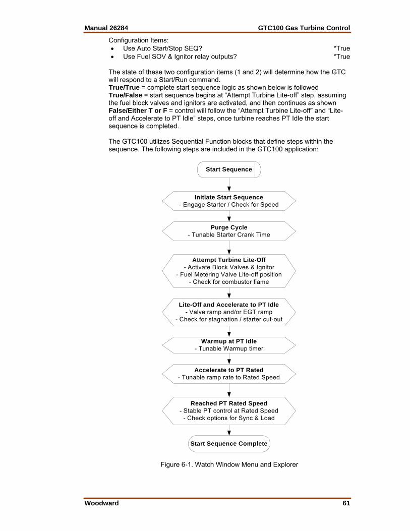
Manual 26284 GTC100 Gas Turbine Control
Woodward 61
Configuration Items: • Use Auto Start/Stop SEQ? *True • Use Fuel SOV & Ignitor relay outputs? *True
The state of these two configuration items (1 and 2) will determine how the GTC will respond to a Start/Run command. True/True = complete start sequence logic as shown below is followed True/False = start sequence begins at “Attempt Turbine Lite-off” step, assuming the fuel block valves and ignitors are activated, and then continues as shown False/Either T or F = control will follow the “Attempt Turbine Lite-off” and “Lite-off and Accelerate to PT Idle” steps, once turbine reaches PT Idle the start sequence is completed. The GTC100 utilizes Sequential Function blocks that define steps within the sequence. The following steps are included in the GTC100 application:
Figure 6-1. Watch Window Menu and Explorer
Start Sequence
Initiate Start Sequence- Engage Starter / Check for Speed
Attempt Turbine Lite-Off- Activate Block Valves & Ignitor
- Fuel Metering Valve Lite-off position- Check for combustor flame
Purge Cycle- Tunable Starter Crank Time
Lite-Off and Accelerate to PT Idle- Valve ramp and/or EGT ramp
- Check for stagnation / starter cut-out
Warmup at PT Idle- Tunable Warmup timer
Accelerate to PT Rated- Tunable ramp rate to Rated Speed
Reached PT Rated Speed- Stable PT control at Rated Speed
- Check options for Sync & Load
Start Sequence Complete

GTC100 Gas Turbine Control Manual 26284
62 Woodward
The following sections will explain the sequence logic above and identify items that are configurable by the user in each step. Initiate Start Sequence After receiving a start command the control will check all of the start permissives, which is a logical AND of the following: • No Shutdowns present • Unit not in Calibrate mode • EGT temp is less than 400 deg F • Fuel Shutoff Valves are Closed • Fuel Metering Valve at minimum position • PT reference set point at minimum value • Any of the customer Start Permissive inputs • Not in a Manual Crank mode If these are all TRUE then the control will energize the Motor Starter relay output and wait to detect that the PT speed probes are reading a speed above the minimum starter crank speed, if no speed is detected after 30 seconds then an alarm is issued. Once speed is detected the Sequence moves into the Purge Cycle step. Configuration Items: • Minimum Crank Speed (rpm) *500 (100, 2000) • Time to wait for PT Speed detection (sec) *10 (1, 120) Purge Cycle Sequence The control will allow the turbine to crank on the starter motor for the amount of time that the user configures for the purge time. This allows for any required purge of the internal turbine air and any downstream boiler system, if no boiler is present then this time can be minimized. Once this timer is complete the control will move to the Attempt Lite-off step Configuration Items: • Purge Cycle Time (sec) *20 (2, 1200) Attempt Lite-off / Activate Fuel Shutoff Valves & Ignitor At this step the control will issue relay commands to open the fuel shutoff valves for the selected fuel type and turn on the ignitors. The control will wait for the configured time to see that a flame has been established in the combustor (via one of the selected options for flame detection). If the control does not get this indication then a shutdown command is issued and annunciated as a Failed to achieve Lite-off. Once Lite-off is achieved the sequence proceeds to the Lite-off and Accel step. Configuration Items: • Time to wait for Lite-off on Gas Fuel (sec) *10 (2, 30) • Time to wait for Lite-off on Liquid Fuel (sec) *15 (2, 30) • *Note – be sure the time is correct for the chosen fuel.
Manual 26284 GTC100 Gas Turbine Control
Woodward 63
Lite-off and Accel to PT Idle Speed At this step the control begins to ramp open the fuel start ramp and will continue on this control, or one of the other start mode options, up to the minimum PT speed set point. During this acceleration the PT speed will pass through the Starter cutout speed, which is when the Motor Starter relay will drop out. The control has a configurable timer during which it must reach the minimum PT speed set point (PT Idle). If it does not reach PT idle within this time frame a shutdown command is issued and annunciated as a PT Failed to Accel. Once PT Idle is reached then the sequence proceeds to the Warm-up step. Configuration Items: • Maximum Time to Accel to PT Idle (sec) *120 (5, 600) • Motor Starter Cut-out Speed (PT rpm) *2000 (100, 5000) • Turn Ignitors OFF Speed (PT rpm) *2400 (100, 10000) • PT Idle Speed = PT Min Ref Set in System Config PT Idle Warm-up Cycle Sequence At this step the control will hold the unit at the PT Idle speed for the amount of time configured by the user. At the end of this cycle the unit will issue a pulse to begin ramping the PT reference to the rated set point. At this point the sequence proceeds to the Accelerate to PT Rated step. Configuration Items: • Time to Warm-up at PT Idle (sec) *30 (5, 600) • Raise PT Ref at Fast Rate (F=Default Rate) *True • PT Reference Fast Rate (rpm/sec) *100 (5, 1000) Accelerate to PT Rated Sequence At this step the control will begin to raise the PT reference at the default or fast ramp rate, as determined by the user. If PT control at rated speed is not achieved in the configured time allowance then a Shutdown command is issued and annunciated as PT Failed to Accel. It is important to set this timer to a calculated amount of time in which the PT should reach rated speed (using the programmed ramp rate and rpm range between Idle and Rated). Once the unit achieves control at PT Sync the sequence proceeds to the Reached PT rated speed step. Configuration Items: • Maximum Time to Accel to PT Rated (sec) *60 (5, 600) Reached PT Rated Sequence At this step the control looks to determine that the turbine is in PT speed control at rated PT speed. Once this is confirmed the Start Sequence is completed. At this point the Start Sequence is completed.

GTC100 Gas Turbine Control Manual 26284
64 Woodward
Initiate a Normal Stop Sequence The user can elect to initiate a normal stop sequence that will bring the unit down from any operating point at PT Rated or above. The sequence is initiated by receiving a Normal stop command pulse. The control will ramp down the PT reference to the minimum load point and then open the utility/generator breaker. After gaining PT speed control at rated speed, the control will ramp down the PT reference from the rated set point to the minimum set point (PT Idle). Once this is achieved the control will hold the unit at this speed until the configured cool down timer has expired. At this point the control will shutoff fuel (both the metering valve and the shutoff valves). When the EGT temperature falls below 400 degrees F then the unit is considered to be shutdown and the normal stop sequence is complete. Configuration Items: • Time to Cool down at PT Idle (sec) *30 (5, 600) • Minimum Load KW Set Point (kW) *500 (10, 30000)
Alarm Sequence When the fuel control detects an alarm condition, it activates a summary alarm and horn output that can be tied to relay outputs. It also sends information about the specific cause of the alarm out through the Modbus block. The customer can also go into Service mode and view a numeric alarm value that corresponds to the numbered alarms found in Appendix C of this manual. An acknowledge signal will clear the horn annunciation of the event. A reset will clear the alarm if the condition that initiated it no longer exists.
Soft Shutdown Sequence When a soft shutdown occurs, either a fuel control initiated event or a discrete input contact configured for a soft shutdown, the unit will open the Generator Breaker to take all load off of the turbine. The GTC will send information as to the specific cause of the shutdown out through the Modbus block. The customer can also go into Service mode and view a numeric shutdown value that corresponds to the numbered shutdowns found in Appendix C of this manual. An acknowledge signal will clear the horn annunciation of the event. A reset will only clear the shutdown if the condition that initiated it no longer exists. The soft shutdown stack and sequence are overridden if a hard shutdown event occurs. This will make the annunciation of the trip clear to the user by the first out indication. If the GTC annunciates a first out indication for both a soft and a hard shutdown – that indicates that the first event was the soft shutdown event, immediately followed by the hard shutdown event indicated.
Manual 26284 GTC100 Gas Turbine Control
Woodward 65
Hard Shutdown Sequence When a hard shutdown occurs, either a fuel control initiated event or the discrete contact shutdown input, all of the actuator signals go to zero, the fuel shutoff valve outputs (if used) go False, and the Generator Breaker will be commanded Open which will cause the turbine to shutdown. The fuel control will activate a summary shutdown relay output and also send information as to the specific cause of the shutdown out through the Modbus block. The customer can also go into Service mode and view a numeric shutdown value that corresponds to the numbered shutdowns found in Appendix C of this manual. An acknowledge signal will clear the horn annunciation of the event. A reset will only clear the shutdown if the condition that initiated it no longer exists AND the PT speed has dropped below the user defined speed set point. This is done to insure that there is no attempt to re-light the turbine while it is in a shutdown mode. When a hard shutdown occurs it will override the soft shutdown stack – so that those events will not come in as nuisance events, since the breaker will be opened as a result of the hard trip.
Setup of PT Speed Control The GTC100 requires that the user setup reference parameters and dynamic gain values in order to control the PT (Power Turbine) Shaft speed of the turbine. The control will create a ramp function based on the upper and lower reference limits defined by the user. This ramp will move at one of 3 rates – Default, Fast and Instant. The user defines the first 2 of these rates in units of rpm/sec. There are 3 optional speed switches that are connected to relay outputs. These signals can be use to assist any sequencing or auxiliary logic that may be performed by another external device. The speed set points for each of these switches can be defined by the user. There are also a few other PT speed options available for the user. • Option of implementing dual dynamics, such that one set of speed PID gain
values are used in one operating mode (such as Isoch mode) and a second set of dynamics can be used while in a different operating condition (such as Droop mode)
• Ability to enable an PT Overspeed test – which will allow the user to adjust the Overspeed Set Point in the control while operating (THIS DOES NOT BIAS THE PHYSICAL SPEED IN ANY WAY)
• Option to automatically override the failed PT speed probe signals until the control determines that it should be receiving some valid speed signal
These parameters must be defined before the control is used to run the turbine. If the PID gain values are not known, then the control dynamics may be adjusted for desired performance, once the turbine is running, by following the procedure detailed in the Troubleshooting section below. Configuration Items: • Service/Configuration Worksheet: PT SPEED CONTROL SETUP

GTC100 Gas Turbine Control Manual 26284
66 Woodward
Setup of the Accel–CDP/Fuel Limiter Curve The GTC100 requires that the user configure a fuel limiter curve based on the compressor discharge pressure of the turbine. The purpose of this curve is to protect the turbine from overfueling (acceleration limiter) by limiting the maximum fuel valve position as a function of the turbine compressor discharge pressure. The CDP/Fuel Schedule biases on CDP (as the X value) as scaled by the user. The output of the curves block (Y value) limits the LSS bus in scale of 0-100% (that is, if output is 50 for a given input, then fuel flow will not be able to increase above 50% valve demand). There are separate curves for gas and liquid fuel—if the turbine is a single fuel unit then the unused fuel curve should have all Y values set to 100%. To calculate the correct X and Y values for this curve, one of the following methods should be used. • Turbine OEMs typically define a curve of Compressor Discharge Pressure
vs. Fuel (in BTU/hr) in the control or installation manuals for the turbine. The user should get the heating value of the fuel used at their installation site and translate this curve into a CDP vs. Fuel Flow curve. The user should then plot their fuel valve flow output (in pph) versus demanded position (%) and create an appropriate CDP vs. Fuel Valve demand curve. Further information of the creation of this curve can be found in the Troubleshooting section.
• The user could record data from their unit while it is currently running and generate a CDP vs. Fuel Valve demand curve. This method should contain a full range of data points (sub-rated PT speed & under load conditions). The Appendices of this manual contain a sheet to assist in this effort.
Configuration Items: • Service/Configuration Worksheet: CDP TO FUEL LIMIT CURVE
Setup of the Accel PID Setup The GTC100 allows the user to configure an optional acceleration PID to assist in the start-up of the turbine or to protect the turbine from over fueling conditions. The user will configure a speed acceleration limiter curve based on the PT speed of the turbine (as the X value). The output of this curve is the desired acceleration limit of the shaft (rpm/sec) as defined by the user. This output is compared with the calculated PT derivative speed and the error is sent to the PID. The curve is defined with a maximum of 6 breakpoints and should be tuned in sequence from X-Y values 1 through 6. Configuration Items: • Service/Configuration Worksheet: ACCEL Control PID SETUP
Manual 26284 GTC100 Gas Turbine Control
Woodward 67
Setup of the Decel Curve Setup The GTC100 allows the user to configure a curve to protect the turbine from under fueling (flame out) conditions. The user will configure a minimum fuel limiter curve based on the compressor discharge pressure of the turbine. The Decel curve uses CDP (as the X value) as scaled by the user. The output of the curves block (Y value) limits the LSS bus in scale of 0-100% (that is, if the output is 10 for a given input, then fuel flow will not be able to decrease below 10% valve demand). There are separate curves for gas and liquid fuel—if the turbine is a single fuel unit then the unused fuel curve should have all Y values set to 100%. The curve is defined with a maximum of 5 breakpoints and should be tuned in sequence from X-Y values 1 through 5, with any unused points at the end tuned high (out of the way). Configuration Items: • Service/Configuration Worksheet: DECEL CURVE (CDP) SETUP
Setup of CDP Pressure Control The GTC100 allows the user to setup a CDP control loop to limit the maximum CDP pressure of the compressor within the turbine. The user can adjust the CDP set point and dynamic gain values of the PID. This function is typically used as a turbine protection / topping limiter and can also be used to limit the overall horsepower output of the turbine. Configuration Items: • Service/Configuration Worksheet: CDP CONTROL SETUP
Setup of EGT Temperature Control The GTC100 allows the user to setup an EGT control loop to limit the maximum EGT temperature of the exhaust gas output of the turbine. The user can adjust the EGT set point and dynamic gain values of the PID. This function is typically used as a turbine protection / topping limiter. This control loop also has an option to allow the user to include EGT limiting during the initial starting of the turbine. The user can enable this function and setup low temp and high temp set points that will define a ramp which will be used during initial start to limit the fuel valve position through this range. The user must also define a rate at which the control will ramp up the temp set point (from low to high), so that the turbine can continue to accelerate up to PT control. This function helps to eliminate potential overtemp shutdowns on initial startup by providing closed loop control at sub-PT Idle conditions. The EGT control automatically resumes to being a topping control once the turbine has reached PT speed control. Configuration Items: • Service/Configuration Worksheet: EGT CONTROL SETUP

GTC100 Gas Turbine Control Manual 26284
68 Woodward
Setup of Generator Settings The GTC100 allows the user to setup a KW control loop to limit the maximum KW output of the turbine. The user can adjust the KW set point and dynamic gain values of the PID. This function is typically used as a turbine protection / topping limiter and can also be used to limit the overall KW or horsepower output of the turbine. The user can also setup the Droop percentage and define a curve (CDP versus KW) that can be used for load feedback if the KW sensor fails. In the case of a compressor unit, the user can decide to use CDP as load feedback. Configuration Items: • Service/Configuration Worksheet: GENERATOR SETTINGS
Setup of Load Sharing The GTC100 has the capability to communicate with other GTC products, as well as other Woodward power management products, to allow Load Sharing of multiple units on a local power bus. When the units are isolated from the Utility bus, the LON communication link will allow these devices to balance the output of all available units to supply the total load on the local bus. This mode is described as Isochronous Load Sharing. NOTE: If it is desirable to include a unit (or units) that load share via an analog signal (such as a Woodward Real Power Sensor) then another device should be added. The Woodward Load Sharing Interface Module (LSIM – p/n 8239-082) will provide a gateway to convert the analog load share signal into a LON signal that can be tied into the above mentioned digital load sharing products. Configuration Items: Configuration Worksheet: SYSTEM • Use Load Sharing Option *True • Transfer Rate In/Out of LS (sec) *10 (0.1, 60) • Use LON Communication Link *True
Synchronizer The GTC100 control uses digital signal processing techniques to derive both true RMS voltages and relative phase of the fundamental frequencies of the bus and generator voltage wave forms. Digital signal processing techniques offer significantly improved measurement accuracy in the presence of waveform distortions, particularly since the phase measurement does not depend on zero crossings of the waveforms. Either phase matching or slip frequency synchronizing may be selected. Phase matching method controls the engine speed to give zero speed error and minimal phase error between the generator and bus; this provides rapid synchronizing for critical standby power applications. Slip frequency synchronizing guarantees a fixed speed difference between generator and bus. This insures the generator to be faster than the bus and initial power flow is out of the machine for larger generators. For both synchronizing methods, the GTC100 control uses actual slip frequency and breaker delay values to anticipate a minimum phase difference between bus and generator at actual breaker closure. The synchronizer can sense a dead local bus and close the generator circuit breaker automatically when safe to do so. The network communication between GTC100 control assures that multiple generators cannot close simultaneously onto a dead bus.

Manual 26284 GTC100 Gas Turbine Control
Woodward 69
There are four synchronizer modes of operation: Run, Check, Permissive, Off. The mode can be selected through Watch Window or Modbus. The last mode selected by any of these interface methods will be the mode of operation. Off mode, the GTC performs no synchronization functions, The running
sequence would stop with the engine at rated speed, and an external function would be required to close the breaker and continue the sequence.
Check mode is used to confirm that the synchronizer works properly by allowing synchronizing to be performed but not closing the breaker. The Synchronizer status screen can be used to observe the Slip, Phase, and voltage indication, (Displays ++ when matched). In the Check mode these indication must match external metering and wiring before allowing the breaker to close.
Permissive mode is used to replace a sync check relay function, the bias outputs are passive, but the breaker command will be given when speed, phase, and voltage parameters are within the window.
Run/Auto mode is the normal mode with active synchronizing and breaker control.
Additional synchronizer features include: voltage matching, time delayed automatic multi-shot re-closing, and a synchronizer timeout alarm. Raise and lower inputs can be used to manually adjust speed for manual synchronizing. Voltage raise and lower inputs can be used to manually adjust voltage for manual voltage matching. Each of these features may be enabled or disabled during setup. Configuration Items: • Service/Configuration Worksheet: SYNCHRONIZER
Load Control The GTC100 has 3 different modes for controlling the turbine load. Isochronous, Droop and Isochronous Load Sharing Droop Mode When the generator circuit breaker is closed and the utility breaker is closed then the unit is in droop operation. The turbine load will be directly proportional to the speed reference signal, which can be manipulated by Raise/Lower commands, a Remote PT reference signal (analog input) or a Modbus or ServLink DDE communication interface. The load reference can also be driven indirectly through the Process control mode. The typical application of simple load droop operation is with a unit that normally operates in parallel with a Mains (utility) bus. Isochronous Mode When the generator circuit breaker is closed, the utility breaker is open and the Load Sharing mode is not enabled, then the unit is in Isochronous mode and will handle all plant loads up to the upper load output limit of the turbine. The typical application of this mode is when a unit is a stand-alone power generation site that does not tie to the utility or a unit that droops against the utility but needs to maintain all of the plant load when the utility breaker is opened.

GTC100 Gas Turbine Control Manual 26284
70 Woodward
Isochronous Load Sharing Mode When the generator circuit breaker is closed, the utility breaker is open and the Load Sharing mode is Enabled, the unit will Load Share with other units connected to the bus. The load sharing signal will control the load of each engine by slight changes to the speed control’s speed reference. The typical application of this mode is when a unit is part of a group of stand-alone power generation units at a site that does not tie (or is not currently tied to) the utility.
Process Control Process Control is a cascade control mode that manipulates the PT reference to maintain the process operation set point. Flexible controller adjustments, an adjustable deadband, and direct or indirect control action, allow the process control to be used in a wide variety of applications. The typical implementations of this feature include, import/export control, pressure maintenance, or other plant dependent load set point parameters. A 4–20 mA (or 1–5 Vdc) process transmitter provides the process signal to the GTC100 control. The control includes an internal digital process reference value which may be controlled by raise and lower switch contact, or by a Modbus or ServLink communication interface. The output of the process control provides the cascade load reference to the Load control. Adjustable ramps allow smooth entry to or exit from the process control mode. When the process control mode is selected, an adjustable ramp moves the load reference in a direction to reduce the process control error. When the error is minimized, or the reference first reaches either the specified high or low load pick-up limits, the process controller is activated. When unloading from the process control, an adjustable unload ramp provides time controlled unloading to the unload trip level. When load reaches the unload trip level, the GTC100 control automatically issues a breaker open command to remove the generator set from the system. The ramp pause switch input allows holding of the load ramp for cool-down or warm-up purposes. Additional functions include selectable and adjustable process high and low limit switches and alarm activation. When multiple gensets and GTC100 LS controls are connected to a bus in process control mode one unit is automatically assigned as the “Process Master”. Its process control loop then dictates through the LON network the load levels of other gensets on the bus. Configuration Items: • Service/Configuration Worksheet: PROCESS CONTROL

Manual 26284 GTC100 Gas Turbine Control
Woodward 71
VAR/PF Control The VAR/PF functions control the reactive power component of the generator in parallel systems. The reactive load mode can be configured for VAR or Power Factor control. The controller compares the reactive load on the generator with an adjustable internal reference and makes corrections to the set point of the Automatic Voltage Regulator (AVR) until the desired reactive power is obtained. The reactive power level can be maintained while also controlling real load through the generator breaker. The analog voltage bias output can be directly connected to compatible voltage regulators. The control also has raise and lower contact outputs to activate a voltage regulator MOP when an analog input is not provided on the AVR. The GTC100 control has a selectable voltage range alarm that is activated if the analog output to the voltage regulator reaches high or low saturation. The GTC100 control also has selectable and adjustable high and low voltage limit switches and alarm outputs. The GTC100 control provides switch inputs to allow raising or lowering the generator voltage reference. The control also provides a 4–20 mA (or 1–5 Vdc) analog input for kVAR/PF set point control, if desired. The kVAR/PF reference can also be set through a Modbus or ServLink DDE communication interface. While the GTC100 is controlling unit load to accomplish real load (kW) sharing, the voltage of the generators in parallel will be controlled to accomplish equal Power Factor levels of each generator. Configuration Items: • Service/Configuration Worksheet: REACTIVE LOAD CONTROL
Power and Energy Metering The digital signal processing techniques are used to provide significantly improved accuracy and speed of response over conventional analog measurement techniques. Accuracy is improved using rapid sampling of the voltage and current signal waveforms and developing a true RMS measurement. Measuring true RMS power allows optimal accuracy, even in the presence of power line distortions. The PowerSense board receives the PT and CT inputs for both the generator and bus for calculation of parameters for the GTC to use in system control. The algorithms used are based on IEEE 1459-2000. For the generator and bus the following parameters are provided: Hz, Vac, Amps, W, VA, VAR, PF, Phase, Voltage harmonics, Current harmonics, Negative Phase Sequence Voltage, Negative Phase Sequence Current. Available for selection at the 4-20 mA analog outputs: Synchroscope, Generator metering, Mains metering
Protective Relaying Alarms can be configured for generator and bus protective relay (i.e. Reverse power, Under Voltage) functions. Time delay, and separate warning and trip thresholds can be set. A complete list of protective relay functions available is given in the next chapter. Current based protections are implemented using the ANSI/IEEE C37.112 Very Inverse curve. Configuration Items: • Service/Configuration Worksheet: ALM/SD EVENTS

GTC100 Gas Turbine Control Manual 26284
72 Woodward
Tunable Upload/Download Function The TUNABLE UPLOAD & DOWNLOAD functionality is used for downloading or uploading tunables into or out of the control. The tunables may be downloaded from the control to a PC anytime, however the turbine must be shutdown while using the TUNABLE UPLOAD FUNCTION mode.
Entering into I/O Lock mode while the turbine is running will cause an automatic shutdown of the turbine with resulting process stoppage. Do not enter the I/O Lock to upload tunables into the control while the turbine is running.
From WW, go to the Explorer Window and ‘right-mouse’ click on the control (top level). A pull-down menu will appear and the App Settings selection will allow you to Save to File or Load from File. • SAVE = Download the tunables in the control to a file on the user PC • LOAD = Upload tunable settings from a user PC into the control Loading tunables into the control will cause the unit to Lock the I/O and shutdown the turbine.
It is highly recommended that the user keep a current tunable list file available at site. This will make the configuration and setup of a spare unit very simple and assist in troubleshooting system problems.

Manual 26284 GTC100 Gas Turbine Control
Woodward 73
Chapter 7. Generator Protection Functions
Protective Relay Descriptions The table below gives some summary information about each type of protective relay function provided. Details for each follow the table. Note that the Alarm and Pre-Alarm Time Delays are used for both high and low conditions.
Name Functionality TypeGenerator Under/Over Voltage (27,59) Alarm and Pre-Alarm
capability Definite Time
Generator Over/Under Frequency (81O, 81U) Alarm and Pre-Alarm capability
Definite Time
Generator Over/Under Power Alarm and Pre-Alarm capability
Definite Time
Generator Directional Power Relay (32) Alarm and Pre-Alarm capability
Inverse Time
Generator Negative Phase Sequence Over Voltage (47)
Alarm and Pre-Alarm capability
Definite Time
Generator Negative Phase Sequence Over Current (46)
Alarm and Pre-Alarm capability
Definite Time
Generator Phase Over Current (51) Alarm and Pre-Alarm capability
Inverse Time
Generator Directional VAR Relay Alarm and Pre-Alarm capability
Definite Time
Generator Phase Current Differential Imbalance relay (87)
Alarm and Pre-Alarm capability
Inverse Time
Sync Check (25) True / False (no alarm) Definite Time Voltage (VAR/PF) Adjust Limits Reached High and Low Alarms Definite Time Speed / Frequency Mismatch Alarm only Definite Time
Over and Under Voltage The Over and Under Voltage protective relay is definite time. It operates by comparing the actual voltage to the level set points for this relay. The highest voltage of the 3 phase inputs is always used for the Over Voltage protective relay. Likewise, the lowest voltage of the 3 phase inputs is always used for the Under Voltage protective relay. Once an alarm is issued, it is latched until the GTC is reset. The generator Under Voltage relay is automatically disabled anytime the generator breaker is open. The Bus Under Voltage relay, Generator and Bus Over Voltage relays are not inhibited by breaker position. The action to be taken for an Over Voltage Pre-Alarm, Over Voltage Alarm, Under Voltage Pre-Alarm, and Under Voltage Alarm are all independently configurable. There are separate Delay times for Pre-Alarm and Alarm. The delay times for Over Voltage and Under Voltage are identical but Generator and Bus are independently configured. The Alarm and Pre-Alarm trigger levels for an Over Voltage Pre-Alarm, Over Voltage Alarm, Under Voltage Pre-Alarm, and Under Voltage Alarm are all independently configurable. The worst case phase voltage must exceed the configured level continuously for the delay time before the Alarm or Pre-Alarm action is taken.
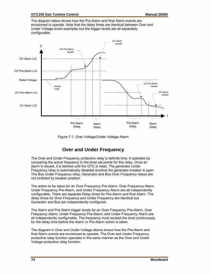
GTC100 Gas Turbine Control Manual 26284
74 Woodward
The diagram below shows how the Pre-Alarm and final Alarm events are envisioned to operate. Note that the delay times are identical between Over and Under Voltage event examples but the trigger levels are all separately configurable.
V
t
OV Alarm LVL
UV Alarm LVL
UV Pre-Alarm LVL
OV Pre-Alarm LVL
Rated Voltage
OV Pre-AlarmIssued
Pre-AlarmDelay
AlarmDelay
OV AlarmIssued
Pre-AlarmDelay
AlarmDelay
UV Pre-AlarmIssued
UV AlarmIssued
ActualVolts
Figure 7-1. Over Voltage/Under Voltage Alarm
Over and Under Frequency The Over and Under Frequency protective relay is definite time. It operates by comparing the actual frequency to the level set points for this relay. Once an alarm is issued, it is latched until the GTC is reset. The generator Under Frequency relay is automatically disabled anytime the generator breaker is open. The Bus Under Frequency relay, Generator and Bus Over Frequency relays are not inhibited by breaker position. The action to be taken for an Over Frequency Pre-Alarm, Over Frequency Alarm, Under Frequency Pre-Alarm, and Under Frequency Alarm are all independently configurable. There are separate Delay times for Pre-Alarm and final Alarm. The delay times for Over Frequency and Under Frequency are identical but Generator and Bus are independently configured. The Alarm and Pre-Alarm trigger levels for an Over Frequency Pre-Alarm, Over Frequency Alarm, Under Frequency Pre-Alarm, and Under Frequency Alarm are all independently configurable. The frequency must exceed the level continuously for the delay time before the Alarm or Pre-Alarm action is taken. The diagram in Over and Under Voltage above shows how the Pre-Alarm and final Alarm events are envisioned to operate. The Over and Under Frequency protective relay function operates in the same manner as the Over and Under Voltage protective relay function.
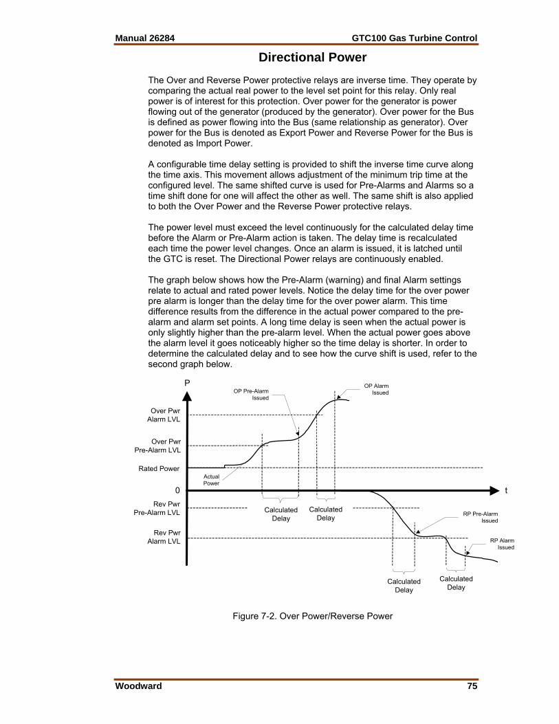
Manual 26284 GTC100 Gas Turbine Control
Woodward 75
Directional Power The Over and Reverse Power protective relays are inverse time. They operate by comparing the actual real power to the level set point for this relay. Only real power is of interest for this protection. Over power for the generator is power flowing out of the generator (produced by the generator). Over power for the Bus is defined as power flowing into the Bus (same relationship as generator). Over power for the Bus is denoted as Export Power and Reverse Power for the Bus is denoted as Import Power. A configurable time delay setting is provided to shift the inverse time curve along the time axis. This movement allows adjustment of the minimum trip time at the configured level. The same shifted curve is used for Pre-Alarms and Alarms so a time shift done for one will affect the other as well. The same shift is also applied to both the Over Power and the Reverse Power protective relays. The power level must exceed the level continuously for the calculated delay time before the Alarm or Pre-Alarm action is taken. The delay time is recalculated each time the power level changes. Once an alarm is issued, it is latched until the GTC is reset. The Directional Power relays are continuously enabled. The graph below shows how the Pre-Alarm (warning) and final Alarm settings relate to actual and rated power levels. Notice the delay time for the over power pre alarm is longer than the delay time for the over power alarm. This time difference results from the difference in the actual power compared to the pre-alarm and alarm set points. A long time delay is seen when the actual power is only slightly higher than the pre-alarm level. When the actual power goes above the alarm level it goes noticeably higher so the time delay is shorter. In order to determine the calculated delay and to see how the curve shift is used, refer to the second graph below.
P
t
Over PwrAlarm LVL
Rev PwrAlarm LVL
Rev Pwr Pre-Alarm LVL
Over Pwr Pre-Alarm LVL
Rated Power
OP Pre-AlarmIssued
CalculatedDelay
CalculatedDelay
OP AlarmIssued
CalculatedDelay
CalculatedDelay
RP Pre-AlarmIssued
RP AlarmIssued
ActualPower
0
Figure 7-2. Over Power/Reverse Power

GTC100 Gas Turbine Control Manual 26284
76 Woodward
The graph below shows how the inverse time curve is applied to the directional power protective relay. Note the same curve shift applies to both Over and Reverse Power. Likewise, for the Bus, the same curve shift would apply to both Import and Export Power but is different than the curve shift used for the generator directional power protective relay.
P
t
Over PwrAlarm LVL
Rev PwrAlarm LVL
Rev Pwr Pre-Alarm LVL
Over Pwr Pre-Alarm LVL
Rated Power
Calculated OPPre-Alarm Delay
Calculated RPAlarm Delay
0
Curve Shift(same as above)
Curve Shift(same as below)
Calculated RPPre-Alarm Delay
Calculated OPAlarm Delay
Figure 7-3. Over Power/Reverse Power Time Delay
Negative Phase Sequence Over Voltage Negative Phase Sequence Voltage (NPS) is a measure of the imbalance in a three phase system. Any imbalance due to unequal voltage amplitude of the three phases or a phase angle error between phases creates NPS voltage. A completely balanced system with positive phase sequence generates 0% NPS voltage. Complete loss of one phase results in 50% NPS voltage, a 100% NPS voltage would result from a balanced system with reversed phase sequence. The NPS protection function must know the correct (expected) phase rotation in order to function properly. Typical causes of voltage unbalance are large unbalanced loads (single phase loads in the system) and unbalances in the supply due to transformer designs or other customer loads in the power system. The most common effect of voltage unbalance (detected by NPS voltage) is rotor overheating on 3-phase motors. For installations where significant regenerated EMF may occur (lifts, cranes, or similar), a sensitivity of 5%-7% is recommended above what is necessary for the system unbalance. To avoid tripping on system transient disturbances, this relay should be configured with a timeout from 2 to 4 seconds.
Manual 26284 GTC100 Gas Turbine Control
Woodward 77
This Negative Phase Sequence Over Voltage protective relay is a definite time relay. As the name implies, it tracks levels ABOVE a configured setting. It operates by comparing the actual Negative Phase Sequence Voltage with the level set point for this relay. Once an alarm is issued, it is latched until the GTC is reset. The Negative Phase Sequence Over Voltage relays are continuously enabled. The actions to be taken for a Negative Phase Sequence Over Voltage Pre-Alarm or a Negative Phase Sequence Over Voltage Alarm are both independently configurable. The Negative Phase Sequence Over Voltage trigger levels are also independently configurable for the Pre-Alarm and Alarm. There are separate Delay times for Pre-Alarm and Alarm. The Negative Phase Sequence Voltage must exceed the trigger level continuously for the delay time before the Alarm or Pre-Alarm action is taken. The diagram in Over and Under Voltage above shows how the Pre-Alarm and final Alarm events are envisioned to operate. Only the Over Voltage portion of the diagram is used. The Negative Phase Sequence Over Voltage protective relay function operates in the same manner as the Over Voltage protective relay function.
Negative Phase Sequence Over Current This Negative Phase Sequence Over Current protective relay is a definite time relay. The negative phase sequence over current is derived the same as the voltage above. Once an alarm is issued, it is latched until the GTC is reset. The Negative Phase Sequence Over Current relays are continuously enabled. The actions to be taken for a Negative Phase Sequence Over Current Pre-Alarm or a Negative Phase Sequence Over Current Alarm are both independently configurable. The Negative Phase Sequence Over Current trigger levels are also independently configurable for the Pre-Alarm and Alarm. There are separate Delay times for Pre-Alarm and Alarm. The Negative Phase Sequence Current must exceed the trigger level continuously for the delay time before the Alarm or Pre-Alarm action is taken. The diagram in Over and Under Voltage above shows how the Pre-Alarm and Alarm events are envisioned to operate. Only the Over Voltage portion of the diagram is used. The Negative Phase Sequence Over Current protective relay function operates in the same manner as the Over Voltage protective relay function.
Phase Over Current The Phase Over Current protective relay is an inverse time relay. It operates by comparing the actual phase current to the level set point for this relay. The highest current of the 3 phase inputs is always used for the Phase Over Current protective relay. Total current is not evaluated. This protective relay is NOT meant to replace a breaker. A configurable time delay setting is provided to shift the inverse time curve along the time axis. This movement allows adjustment of the minimum trip time at the configured level. The same shifted curve is used for Pre-Alarms and Alarms so a time shift done for one will affect the other as well.

GTC100 Gas Turbine Control Manual 26284
78 Woodward
The worst case current level must exceed the configured level continuously for the calculated delay time before the Alarm or Pre-Alarm action is taken. The delay time is always being recalculated for the present current level input. Once an alarm is issued, it is latched until the GTC is reset. The Phase Over Current protective relay is continuously enabled. The diagram in Directional Power above shows how the Pre-Alarm and final Alarm events are envisioned to operate as well as the interaction with the inverse time curve. Only the Over Power portion of the diagram is used. The Phase Over Current protective relay function operates in the same manner as the Over Power protective relay function.
Directional VAR The Over and Reverse VAR (Import and Export VAR) protective relay is definite time. It operates by comparing the actual reactive power to the level set points for this relay. Only reactive power is of interest for this protection. Over VAR for the generator is reactive power flowing out of the generator (produced by the generator) and is representative of lagging power factor. Over VAR for the Bus is defined as reactive power flowing into the Bus. We will refer to this as Export VAR for the Bus. Reverse VAR for the Bus will be referred to as Import VAR. Once an alarm is issued, it is latched until the GTC is reset. The action to be taken for an Over (Export) VAR Pre-Alarm, Over (Export) VAR Alarm, Reverse (Import) VAR Pre-Alarm, and Reverse (Import) VAR Alarm are all independently configurable. There are separate Delay times for Pre-Alarm and Alarm. The delay times for Forward and Reverse VAR are identical but Generator and Bus are independently configured. The Alarm and Pre-Alarm trigger levels for an Over (Export) VAR Pre-Alarm, Over (Export) VAR Alarm, Reverse (Import) VAR Pre-Alarm, and Reverse (Import) VAR Alarm are all independently configurable. The reactive power level must exceed the trigger level continuously for the delay time before the Alarm or Pre-Alarm action is taken. The diagram in Over and Under Voltage above shows how the Pre-Alarm and Alarm events are envisioned to operate. The Directional VAR protective relay function operates in the same manner as the Over and Under Voltage protective relay function.
Phase Current Imbalance The Phase-balance Current protective relay is an inverse time relay. It operates by comparing the actual current between each phase to the level set point for this relay. The highest differential current of the 3 comparisons is always used for the Phase Current Imbalance protective relay. A configurable time delay setting is provided to shift the inverse time curve along the time axis. This movement allows adjustment of the minimum trip time at the configured level. The same shifted curve is used for Pre-Alarms and Alarms so a time shift done for one will affect the other as well. The worst case current differential must exceed the trigger level continuously for the calculated delay time before the Alarm or Pre-Alarm action is taken. The delay time is always being recalculated for the present current imbalance level input. Once an alarm is issued, it is latched until the GTC is reset. The Phase Current Differential protective relay is continuously enabled.

Manual 26284 GTC100 Gas Turbine Control
Woodward 79
The graph below shows how the Pre-Alarm and Alarm settings relate to actual current imbalance levels. The current imbalance levels are internally normalized against the rated current. This provides the inverse time function with a valid comparison because the IEEE definition is only valid above 1 per unit. Nevertheless, the configuration values for the Alarm and Pre-Alarm Level are to be entered as the actual allowed difference. The GTC will automatically add Rated Current to the configured value.
A
t
Alarm LVL
Pre-Alarm LVL
Pre-AlarmIssued
CalculatedDelay
CalculatedDelay
AlarmIssued
Actual Current Imbalance
0
Figure 7-4. Phase Current Imbalance
In order to determine the calculated delay and to see how the curve shift is used, refer to the graph below. The Phase Current Imbalance protective relay function operates in nearly the same manner as the Over Power protective relay function except that rated current is automatically added into the percentage calculation for the IEEE inverse time curve input. The information is provided in case an exact trip time must be calculated.
A
t
Alarm LVL +Rated Current
Pre-Alarm LVL+Rated Current
Rated Current
CalculatedPre-Alarm Delay
Curve Shift
CalculatedAlarm Delay
Figure 7-5. Phase-Balance Current, Inverse Time Delay

GTC100 Gas Turbine Control Manual 26284
80 Woodward
Sync Check The GTC synchronizer provides the Sync Check protective relay function. It is listed here due to its nature as a protective relay. It is enabled during synchronizing only. The synchronizer always performs a Sync Check function regardless of the configured mode since it will never assert the breaker close output unless the two A-phase inputs are in sync with each other. The synchronizer may also be placed in the Permissive Mode which mimics a typical ANSI 25 device by closing the output when the two sources are in sync.
Voltage (VAR/PF) Bias Limit Reached The Limits Reached alarm function applies to the two closed loop analog outputs – one for voltage adjust and the other for speed adjust. Each output has separate alarm due to exceeding the limits in the high direction or low direction. There is a fixed timeout of 10 seconds to ensure that a short bump into the limit does not cause an alarm. The alarm action is configurable. This protection determines if the analog output or digital outputs (depending on configuration) have reached their limits. Since a digital output has no definite limit, the protection also reacts to the situation where the control is requesting more adjustment but the system is not responding. This condition would be indicative of reaching a limit.
Speed / Frequency Mismatch The Speed/Frequency Mismatch protection watches the magnetic pickup speed input and the measured frequency on the generator input. It compares the scaled value of the MPU (the rpm value) to the frequency using a simple formula. The formula also depends on the configured number of generator poles.
120# RPMGenPolesFrequency •
=
The purpose of this protection is partly to identify an incorrect configuration for the number of teeth but primarily to diagnose a failed MPU signal or a generator failure. If the one of the signals fail, a mismatch will occur between the measured MPU speed and the measured generator frequency. Since over speed is determined from the MPU input, this protection is an important adder to the over speed protection. A fixed delay of 5 seconds is incorporated. A one hertz margin is allowed. How the alarm reacts is configurable.
Inverse Time Curve All protective relays that utilize inverse time trips will use the same curve shape as defined below. Each relay will be allowed to independently adjust the curve along the time axis. This adjustment does not alter the curve shape. The reason for the adjustment is to allow fine tuning of the alarm levels and timing. The GTC takes the ratio of the input being used (phase current, power, etc.) to the rated value of that unit. The inverse time curve always uses a ratio of rated for its data element.
Manual 26284 GTC100 Gas Turbine Control
Woodward 81
The inverse time curve plotted below is defined in IEEE C37.112 as the Very Inverse formula
DBx
ATime p ∗⎟⎠⎞
⎜⎝⎛ +
−=
1 where:
Time The amount of time to wait before an alarm is issued for the given value of x. As x increases, the time will decrease.
X A ratio of the measured parameter in protection to rated value. A IEEE defined constant that affects the curve shape. It is fixed at 19.61. B IEEE defined constant that affects the curve position. It is fixed at 0.491 P IEEE defined constant that defines the curve type. It is fixed at 2. D Adjustable time delay. This allows the curve to be shifted along the time
axis by a variable amount., 0.01 to 10.0, default =1.0 For high alarms: If the input is less than the Alarm level and Pre-Alarm level, no action will be taken. When the input is above the Pre-Alarm level, the configured action will be taken for the pre-alarm after the timeout defined by the formula. When the input is above the Alarm level, the appropriate (and typically more severe) action will be taken after the (shorter) timeout defined by the formula. For low alarms: If the input is greater than the Alarm level and Pre-Alarm level, no action will be taken. When the input is less than the Pre-Alarm level, the configured action will be taken for the pre-alarm after the timeout defined by the formula. When the input is less than the Alarm level, the appropriate (and typically more severe) action will be taken after the (shorter) timeout defined by the formula. The IEEE curve implemented is the Very Inverse curve defined in IEEE C37.112 and also matches the IEC curve defined in IEC 255-03 except for the additional time shift (B) that is not defined in IEC. The formula will not function at rated or below rated for the parameter in protection. Therefore, if a trip value is set at or below rated, the timeout for these conditions will be fixed at 10 seconds. This causes a discontinuity in the curve at 100% rated. The values for A and B in the IEEE formula change at the discontinuity point. The constant A becomes 0 and the constant B becomes 10. Due to the location of the B constant and the D variable, the 10 second timeout will also adjust with the curve shift. The figure below is a set of curves showing the IEEE Very Inverse formula plotted three times. The center plot is the default curve with no level shift, Shift value = 1.0. The upper plot is the same curve with a level shift of five. The lower plot is the same curve with a level shift of 0.1. Note the curve shape does not change. Also note the fixed timing at or below rated as shown by the straight horizontal line; and note how the fixed timing is varied with the curve shift. The GTC curve does extend to the right beyond the time shown. Also shown below is a figure with the Inverse Time Curve converted to linear axis scale. The values used in the GTC extend above 25 second delay between 1.0 and 1.35, and also extend to the right beyond the ratio of 5.0. Example: If the alarm set point is 150% of the rated (1.5 ratio) and the input is at this set point value and the shift = 1.0, the delay will be 16 seconds. When shift = 5, delay will be 80 seconds. When shift = 0.1, delay will be 1.6 seconds. As the input value exceeds the set point, the delay will become shorter. Example: For an Over Current Trip Relay function: If Rated Phase Current is 500 Amps, and a trip delay of 5.0 second is desired at 700 Amp. Ratio = 1.4, from formula (or reading from curve below) the Normalized Delay = 20.9 sec. 5.0 / 21.0 = 0.24
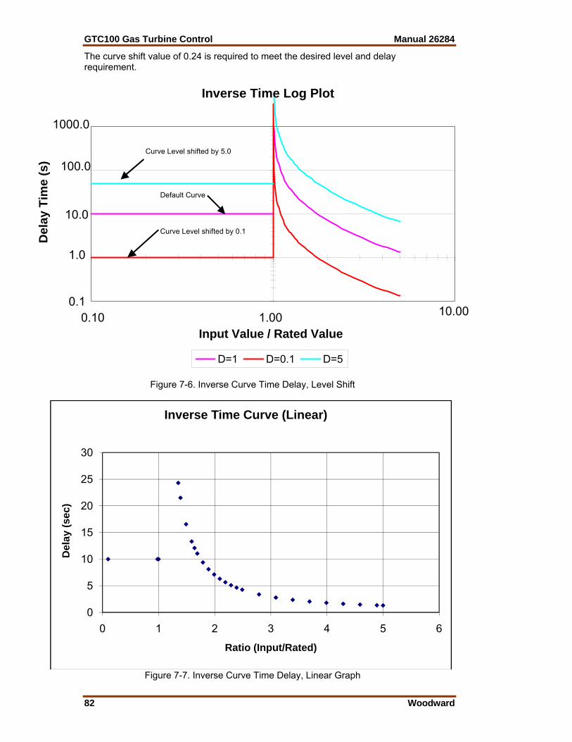
GTC100 Gas Turbine Control Manual 26284
82 Woodward
The curve shift value of 0.24 is required to meet the desired level and delay requirement.
Inverse Time Log Plot
0.1
1.0
10.0
100.0
1000.0
0.10 1.00 10.00
Input Value / Rated Value
Del
ay T
ime
(s)
Default Curve
Curve Level shifted by 0.1
Curve Level shifted by 5.0
D=1 D=0.1 D=5
Figure 7-6. Inverse Curve Time Delay, Level Shift
Figure 7-7. Inverse Curve Time Delay, Linear Graph
0
5
10
15
20
25
30
0 1 2 3 4 5 6
Del
ay (s
ec)
Ratio (Input/Rated)
Inverse Time Curve (Linear)
Manual 26284 GTC100 Gas Turbine Control
Woodward 83
Chapter 8. Troubleshooting
Dynamic Response Problems PID Controller Tuning The majority of problems associated with the control of the turbine can be attributed to poor tuning of the PID control loops. These problems include overspeeding, overtemping, and flaming out as well as many others. For example, if the turbine control is hunting, the loop that is currently controlling the fuel valve is most likely incorrectly tuned and could cause sufficient overshoot to overspeed or overtemp the turbine. Some general tuning guidelines are outlined below.
Tuning of PID loops should only be performed by qualified personnel that have a good understanding how the control should be performing. Improper tuning can result in overspeed or overtemp conditions, which could cause damage to the turbine or possible injury or death to personnel.
The quality of regulation obtained from an automatic control system depends upon the adjustments that are made to the various controller modes. Best results are obtained when the adjustment (tuning) is done systematically. Prior training and experience in controller tuning are desirable for effective application of this procedure. This procedure will lead to controller settings, which, after a load change, will provide: • Process control without sustained cycling • Process recovery in a minimum time Controller settings derived for given operating conditions are valid over a narrow range of load change. The settings made for one operating set of conditions may result in excessive cycling or highly damped response at some other operating condition. This procedure should be applied under the most difficult operating conditions to assure conservative settings over the normal operating range. There are several methods of controller tuning in use. The following procedure presents one, which will be easy to use, and at the same time minimize process upset. This method is one of systematic trial and error. The method given is based upon the 1/4-ratio decay cycle. The peak of each cycle is 1/4 of the preceding one. The objective is to produce a trace as shown in Figure 8-1. It is good practice to keep the average of the set point changes near the normal set point of the process to avoid excessive departure from normal operating level. After each set point change, allow sufficient time to observe the effect of the last adjustment. It is wise to wait until approximately 90% of the change has been completed.
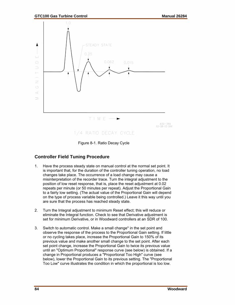
GTC100 Gas Turbine Control Manual 26284
84 Woodward
Figure 8-1. Ratio Decay Cycle Controller Field Tuning Procedure 1. Have the process steady state on manual control at the normal set point. It
is important that, for the duration of the controller tuning operation, no load changes take place. The occurrence of a load change may cause a misinterpretation of the recorder trace. Turn the integral adjustment to the position of low reset response, that is, place the reset adjustment at 0.02 repeats per minute (or 50 minutes per repeat). Adjust the Proportional Gain to a fairly low setting. (The actual value of the Proportional Gain will depend on the type of process variable being controlled.) Leave it this way until you are sure that the process has reached steady state.
2. Turn the Integral adjustment to minimum Reset effect; this will reduce or
eliminate the Integral function. Check to see that Derivative adjustment is set for minimum Derivative, or in Woodward controllers at an SDR of 100.
3. Switch to automatic control. Make a small change* in the set point and
observe the response of the process to the Proportional Gain setting. If little or no cycling takes place, increase the Proportional Gain to 150% of its previous value and make another small change to the set point. After each set point change, increase the Proportional Gain to twice its previous value until an "Optimum Proportional" response curve (see below) is obtained. If a change in Proportional produces a "Proportional Too High" curve (see below), lower the Proportional Gain to its previous setting. The "Proportional Too Low" curve illustrates the condition in which the proportional is too low.
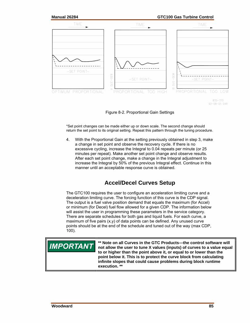
Manual 26284 GTC100 Gas Turbine Control
Woodward 85
Figure 8-2. Proportional Gain Settings
*Set point changes can be made either up or down scale. The second change should return the set point to its original setting. Repeat this pattern through the tuning procedure. 4. With the Proportional Gain at the setting previously obtained in step 3, make
a change in set point and observe the recovery cycle. If there is no excessive cycling, increase the Integral to 0.04 repeats per minute (or 25 minutes per repeat). Make another set point change and observe results. After each set point change, make a change in the Integral adjustment to increase the Integral by 50% of the previous Integral effect. Continue in this manner until an acceptable response curve is obtained.
Accel/Decel Curves Setup The GTC100 requires the user to configure an acceleration limiting curve and a deceleration limiting curve. The forcing function of this curve is the CDP signal. The output is a fuel valve position demand that equals the maximum (for Accel) or minimum (for Decel) fuel flow allowed for a given CDP. The information below will assist the user in programming these parameters in the service category. There are separate schedules for both gas and liquid fuels. For each curve, a maximum of five pairs (x,y) of data points can be defined. Any unused curve points should be at the end of the schedule and tuned out of the way (max CDP, 100).
** Note on all Curves in the GTC Products—the control software will not allow the user to tune X values (inputs) of curves to a value equal to or higher than the point above it, or equal to or lower than the point below it. This is to protect the curve block from calculating infinite slopes that could cause problems during block runtime execution. **
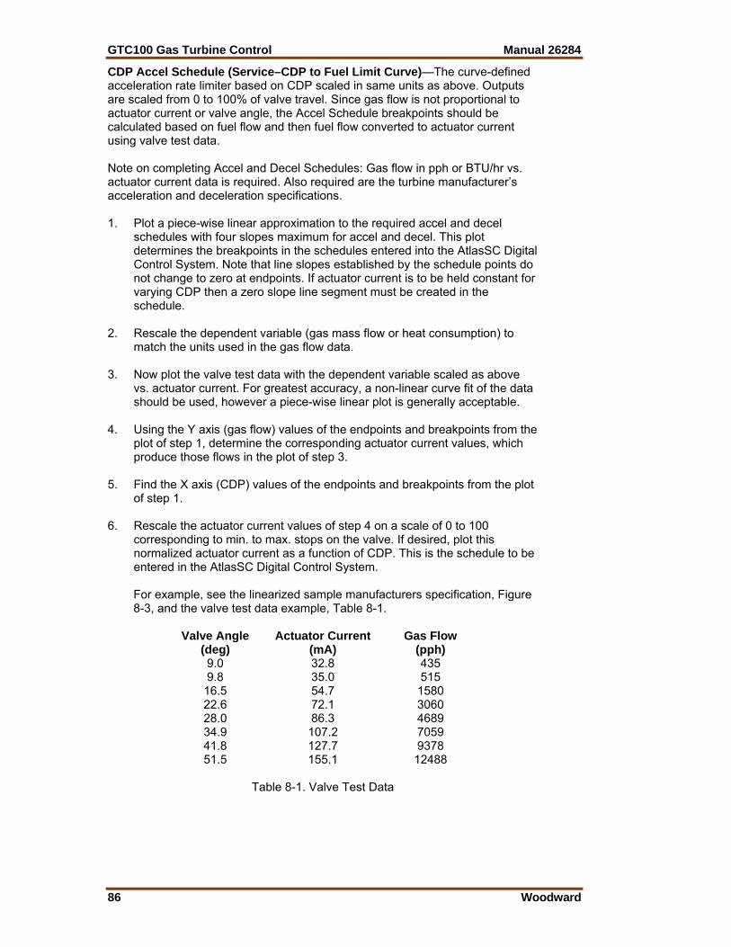
GTC100 Gas Turbine Control Manual 26284
86 Woodward
CDP Accel Schedule (Service–CDP to Fuel Limit Curve)—The curve-defined acceleration rate limiter based on CDP scaled in same units as above. Outputs are scaled from 0 to 100% of valve travel. Since gas flow is not proportional to actuator current or valve angle, the Accel Schedule breakpoints should be calculated based on fuel flow and then fuel flow converted to actuator current using valve test data. Note on completing Accel and Decel Schedules: Gas flow in pph or BTU/hr vs. actuator current data is required. Also required are the turbine manufacturer’s acceleration and deceleration specifications. 1. Plot a piece-wise linear approximation to the required accel and decel
schedules with four slopes maximum for accel and decel. This plot determines the breakpoints in the schedules entered into the AtlasSC Digital Control System. Note that line slopes established by the schedule points do not change to zero at endpoints. If actuator current is to be held constant for varying CDP then a zero slope line segment must be created in the schedule.
2. Rescale the dependent variable (gas mass flow or heat consumption) to
match the units used in the gas flow data. 3. Now plot the valve test data with the dependent variable scaled as above
vs. actuator current. For greatest accuracy, a non-linear curve fit of the data should be used, however a piece-wise linear plot is generally acceptable.
4. Using the Y axis (gas flow) values of the endpoints and breakpoints from the
plot of step 1, determine the corresponding actuator current values, which produce those flows in the plot of step 3.
5. Find the X axis (CDP) values of the endpoints and breakpoints from the plot
of step 1. 6. Rescale the actuator current values of step 4 on a scale of 0 to 100
corresponding to min. to max. stops on the valve. If desired, plot this normalized actuator current as a function of CDP. This is the schedule to be entered in the AtlasSC Digital Control System.
For example, see the linearized sample manufacturers specification, Figure
8-3, and the valve test data example, Table 8-1. Valve Angle Actuator Current Gas Flow (deg) (mA) (pph) 9.0 32.8 435 9.8 35.0 515 16.5 54.7 1580 22.6 72.1 3060 28.0 86.3 4689 34.9 107.2 7059 41.8 127.7 9378 51.5 155.1 12488
Table 8-1. Valve Test Data
Manual 26284 GTC100 Gas Turbine Control
Woodward 87
Figure 8-3. Linearized Flow Schedule Given the gas lower heating value of 20 000 BTU/lbm, flow in million BTU/h can be rescaled for pph as in the valve test data. The accel schedule breakpoint is at 7250 pph (145 million BTU/h) fuel flow and 180 psia CDP. From the valve test data, this point corresponds to 108.9 mA of actuator current. For this example, a linear interpolation between valve test data points was used to find the actuator current (step 3 above). However, better accuracy would result using a non-linear curve fit. Two more points are required to establish the two-slope accel schedule. The first is (40 psia, 1600 pph) which corresponds to 54.9 mA. The second endpoint is (240 psia, 10500 pph) which corresponds to an actuator current of 137.6 mA. Now rescale actuator current for 0 to 100 for min. to max. travel of the valve. From the valve data, min. travel is at 35.0 mA and max travel is at 155.1 mA. This gives: CDP Act. Current Act. Signal (psia) (mA) (0 to 100) 40 54.9 16.6 180 108.9 61.5 240 137.6 85.4 Where CDP is the Accel Schedule input value to be entered and ACT. SIGNAL is the output value to be entered. The same procedure is followed for the Decel Schedule. DN/DT Accel Schedule is biased by GG speed derivative. When DN/DT PID control is used, the acceleration (or deceleration) schedule values must be in terms of GG speed (for inputs) and GG derivative (for outputs).
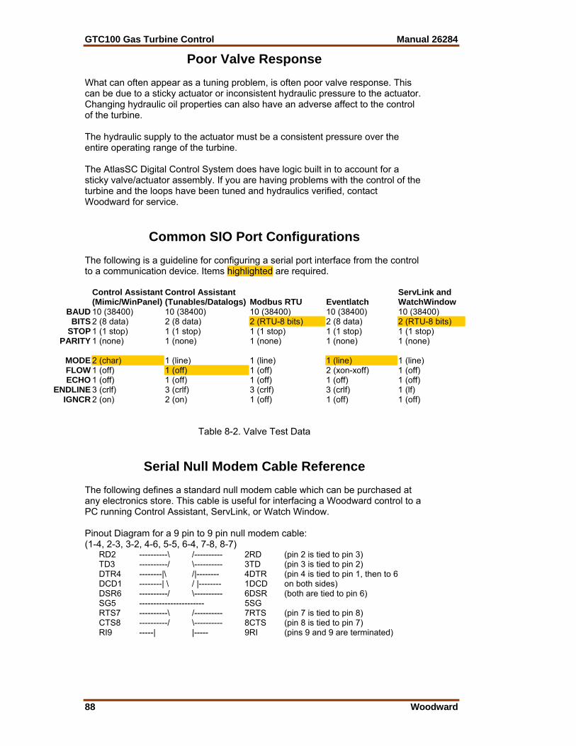
GTC100 Gas Turbine Control Manual 26284
88 Woodward
Poor Valve Response What can often appear as a tuning problem, is often poor valve response. This can be due to a sticky actuator or inconsistent hydraulic pressure to the actuator. Changing hydraulic oil properties can also have an adverse affect to the control of the turbine. The hydraulic supply to the actuator must be a consistent pressure over the entire operating range of the turbine. The AtlasSC Digital Control System does have logic built in to account for a sticky valve/actuator assembly. If you are having problems with the control of the turbine and the loops have been tuned and hydraulics verified, contact Woodward for service.
Common SIO Port Configurations The following is a guideline for configuring a serial port interface from the control to a communication device. Items highlighted are required.
Control Assistant (Mimic/WinPanel)
Control Assistant (Tunables/Datalogs) Modbus RTU Eventlatch
ServLink and WatchWindow
BAUD 10 (38400) 10 (38400) 10 (38400) 10 (38400) 10 (38400) BITS 2 (8 data) 2 (8 data) 2 (RTU-8 bits) 2 (8 data) 2 (RTU-8 bits)
STOP 1 (1 stop) 1 (1 stop) 1 (1 stop) 1 (1 stop) 1 (1 stop) PARITY 1 (none) 1 (none) 1 (none) 1 (none) 1 (none)
MODE 2 (char) 1 (line) 1 (line) 1 (line) 1 (line) FLOW 1 (off) 1 (off) 1 (off) 2 (xon-xoff) 1 (off) ECHO 1 (off) 1 (off) 1 (off) 1 (off) 1 (off)
ENDLINE 3 (crlf) 3 (crlf) 3 (crlf) 3 (crlf) 1 (lf) IGNCR 2 (on) 2 (on) 1 (off) 1 (off) 1 (off)
Table 8-2. Valve Test Data
Serial Null Modem Cable Reference The following defines a standard null modem cable which can be purchased at any electronics store. This cable is useful for interfacing a Woodward control to a PC running Control Assistant, ServLink, or Watch Window. Pinout Diagram for a 9 pin to 9 pin null modem cable: (1-4, 2-3, 3-2, 4-6, 5-5, 6-4, 7-8, 8-7)
RD2 ----------\ /---------- 2RD (pin 2 is tied to pin 3) TD3 ----------/ \---------- 3TD (pin 3 is tied to pin 2) DTR4 --------|\ /|-------- 4DTR (pin 4 is tied to pin 1, then to 6 DCD1 --------| \ / |-------- 1DCD on both sides) DSR6 ----------/ \---------- 6DSR (both are tied to pin 6) SG5 ----------------------- 5SG RTS7 ----------\ /---------- 7RTS (pin 7 is tied to pin 8) CTS8 ----------/ \---------- 8CTS (pin 8 is tied to pin 7) RI9 -----| |----- 9RI (pins 9 and 9 are terminated)
Manual 26284 GTC100 Gas Turbine Control
Woodward 89
Pin Definitions CTS Clear To Send. The CTS line is asserted by the PC (as DCE device) when it is
ready to receive data. DCD Data Carrier Detect. The DCD line is asserted when the data link is
established. DCE Data Communications Equipment. Refers to the modem in a computer to
modem setup. DSR Data Set Ready. The DSR line is asserted by the DCE when it is ready to
communicate with the DTE. DTE Data Terminal Equipment. Refers to the computer in a computer to modem
setup. DTR Data Terminal Ready. The DTR line is asserted by the DTE when it is ready to
communicate with the DCE. FG Field Ground. A protective line used to ground the DCE. RD Receive Data. The RD line is used by the DCE to send data to the DTE. RI Ring Indicator. The RI line is asserted by the DCE when a ring is detected. RTS Request To Send. The RTS line is asserted by the DTE when it wants to
transmit data to the DCE. SG Signal Ground. The common return (and voltage baseline) for the various
signal lines. TD Transmit Data. The TD line is used by the DTE to send data to the DCE.

GTC100 Gas Turbine Control Manual 26284
90 Woodward
Chapter 9. Service Options
Product Service Options If you are experiencing problems with the installation, or unsatisfactory performance of a Woodward product, the following options are available: • Consult the troubleshooting guide in the manual. • Contact the manufacturer or packager of your system. • Contact the Woodward Full Service Distributor serving your area. • Contact Woodward technical assistance (see “How to Contact Woodward”
later in this chapter) and discuss your problem. In many cases, your problem can be resolved over the phone. If not, you can select which course of action to pursue based on the available services listed in this chapter.
OEM and Packager Support: Many Woodward controls and control devices are installed into the equipment system and programmed by an Original Equipment Manufacturer (OEM) or Equipment Packager at their factory. In some cases, the programming is password-protected by the OEM or packager, and they are the best source for product service and support. Warranty service for Woodward products shipped with an equipment system should also be handled through the OEM or Packager. Please review your equipment system documentation for details. Woodward Business Partner Support: Woodward works with and supports a global network of independent business partners whose mission is to serve the users of Woodward controls, as described here:
• A Full Service Distributor has the primary responsibility for sales, service, system integration solutions, technical desk support, and aftermarket marketing of standard Woodward products within a specific geographic area and market segment.
• An Authorized Independent Service Facility (AISF) provides authorized service that includes repairs, repair parts, and warranty service on Woodward's behalf. Service (not new unit sales) is an AISF's primary mission.
• A Recognized Engine Retrofitter (RER) is an independent company that does retrofits and upgrades on reciprocating gas engines and dual-fuel conversions, and can provide the full line of Woodward systems and components for the retrofits and overhauls, emission compliance upgrades, long term service contracts, emergency repairs, etc.
• A Recognized Turbine Retrofitter (RTR) is an independent company that does both steam and gas turbine control retrofits and upgrades globally, and can provide the full line of Woodward systems and components for the retrofits and overhauls, long term service contracts, emergency repairs, etc.
A current list of Woodward Business Partners is available at www.woodward.com/support.

Manual 26284 GTC100 Gas Turbine Control
Woodward 91
Woodward Factory Servicing Options The following factory options for servicing Woodward products are available through your local Full-Service Distributor or the OEM or Packager of the equipment system, based on the standard Woodward Product and Service Warranty (5-01-1205) that is in effect at the time the product is originally shipped from Woodward or a service is performed: • Replacement/Exchange (24-hour service) • Flat Rate Repair • Flat Rate Remanufacture Replacement/Exchange: Replacement/Exchange is a premium program designed for the user who is in need of immediate service. It allows you to request and receive a like-new replacement unit in minimum time (usually within 24 hours of the request), providing a suitable unit is available at the time of the request, thereby minimizing costly downtime. This is a flat-rate program and includes the full standard Woodward product warranty (Woodward Product and Service Warranty 5-01-1205). This option allows you to call your Full-Service Distributor in the event of an unexpected outage, or in advance of a scheduled outage, to request a replacement control unit. If the unit is available at the time of the call, it can usually be shipped out within 24 hours. You replace your field control unit with the like-new replacement and return the field unit to the Full-Service Distributor. Charges for the Replacement/Exchange service are based on a flat rate plus shipping expenses. You are invoiced the flat rate replacement/exchange charge plus a core charge at the time the replacement unit is shipped. If the core (field unit) is returned within 60 days, a credit for the core charge will be issued. Flat Rate Repair: Flat Rate Repair is available for the majority of standard products in the field. This program offers you repair service for your products with the advantage of knowing in advance what the cost will be. All repair work carries the standard Woodward service warranty (Woodward Product and Service Warranty 5-01-1205) on replaced parts and labor. Flat Rate Remanufacture: Flat Rate Remanufacture is very similar to the Flat Rate Repair option with the exception that the unit will be returned to you in “like-new” condition and carry with it the full standard Woodward product warranty (Woodward Product and Service Warranty 5-01-1205). This option is applicable to mechanical products only.
GTC100 Gas Turbine Control Manual 26284
92 Woodward
Returning Equipment for Repair If a control (or any part of an electronic control) is to be returned for repair, please contact your Full-Service Distributor in advance to obtain Return Authorization and shipping instructions. When shipping the item(s), attach a tag with the following information: • return number; • name and location where the control is installed; • name and phone number of contact person; • complete Woodward part number(s) and serial number(s); • description of the problem; • instructions describing the desired type of repair. Packing a Control Use the following materials when returning a complete control: • protective caps on any connectors; • antistatic protective bags on all electronic modules; • packing materials that will not damage the surface of the unit; • at least 100 mm (4 inches) of tightly packed, industry-approved packing
material; • a packing carton with double walls; • a strong tape around the outside of the carton for increased strength.
To prevent damage to electronic components caused by improper handling, read and observe the precautions in Woodward manual 82715, Guide for Handling and Protection of Electronic Controls, Printed Circuit Boards, and Modules.
Replacement Parts When ordering replacement parts for controls, include the following information: • the part number(s) (XXXX-XXXX) that is on the enclosure nameplate; • the unit serial number, which is also on the nameplate.

Manual 26284 GTC100 Gas Turbine Control
Woodward 93
Engineering Services Woodward offers various Engineering Services for our products. For these services, you can contact us by telephone, by email, or through the Woodward website. • Technical Support • Product Training • Field Service Technical Support is available from your equipment system supplier, your local Full-Service Distributor, or from many of Woodward’s worldwide locations, depending upon the product and application. This service can assist you with technical questions or problem solving during the normal business hours of the Woodward location you contact. Emergency assistance is also available during non-business hours by phoning Woodward and stating the urgency of your problem. Product Training is available as standard classes at many of our worldwide locations. We also offer customized classes, which can be tailored to your needs and can be held at one of our locations or at your site. This training, conducted by experienced personnel, will assure that you will be able to maintain system reliability and availability. Field Service engineering on-site support is available, depending on the product and location, from many of our worldwide locations or from one of our Full-Service Distributors. The field engineers are experienced both on Woodward products as well as on much of the non-Woodward equipment with which our products interface. For information on these services, please contact us via telephone, email us, or use our website and reference www.woodward.com/support, and then Customer Support.
How to Contact Woodward For assistance, call one of the following Woodward facilities to obtain the address and phone number of the facility nearest your location where you will be able to get information and service.
Electrical Power Systems Facility --------------- Phone Number Australia ----------- +61 (2) 9758 2322 Brazil ------------- +55 (19) 3708 4800 China ------------ +86 (512) 6762 6727 Germany: Kempen --- +49 (0) 21 52 14 51 Stuttgart ----- +49 (711) 78954-0 India --------------- +91 (129) 4097100 Japan -------------- +81 (43) 213-2191 Korea--------------- +82 (51) 636-7080 Poland -------------- +48 12 618 92 00 United States----- +1 (970) 482-5811
Engine Systems Facility --------------- Phone Number Australia ----------- +61 (2) 9758 2322 Brazil ------------- +55 (19) 3708 4800 China ------------ +86 (512) 6762 6727 Germany: Stuttgart ----- +49 (711) 78954-0 India --------------- +91 (129) 4097100 Japan -------------- +81 (43) 213-2191 Korea--------------- +82 (51) 636-7080 The Netherlands - +31 (23) 5661111 United States----- +1 (970) 482-5811
Turbine Systems Facility --------------- Phone Number Australia ----------- +61 (2) 9758 2322 Brazil ------------- +55 (19) 3708 4800 China ------------ +86 (512) 6762 6727 India --------------- +91 (129) 4097100 Japan -------------- +81 (43) 213-2191 Korea--------------- +82 (51) 636-7080 The Netherlands - +31 (23) 5661111 United States----- +1 (970) 482-5811
You can also contact the Woodward Customer Service Department or consult our worldwide directory on Woodward’s website (www.woodward.com/support) for the name of your nearest Woodward distributor or service facility. For the most current product support and contact information, please refer to the latest version of publication 51337 at www.woodward.com/publications.

GTC100 Gas Turbine Control Manual 26284
94 Woodward
Technical Assistance If you need to telephone for technical assistance, you will need to provide the following information. Please write it down here before phoning: General Your Name Site Location Phone Number Fax Number Prime Mover Information Engine/Turbine Model Number Manufacturer Number of Cylinders (if applicable) Type of Fuel (gas, gaseous, steam, etc) Rating Application Control/Governor Information Please list all Woodward governors, actuators, and electronic controls in your system: Woodward Part Number and Revision Letter Control Description or Governor Type Serial Number Woodward Part Number and Revision Letter Control Description or Governor Type Serial Number Woodward Part Number and Revision Letter Control Description or Governor Type Serial Number If you have an electronic or programmable control, please have the adjustment setting positions or the menu settings written down and with you at the time of the call.

Manual 26284 GTC100 Gas Turbine Control
Woodward 95
Appendix A. System Input/Output Signal Layout
This appendix contains the control wiring diagrams.

GTC100 Gas Turbine Control Manual 26284
96 Woodward
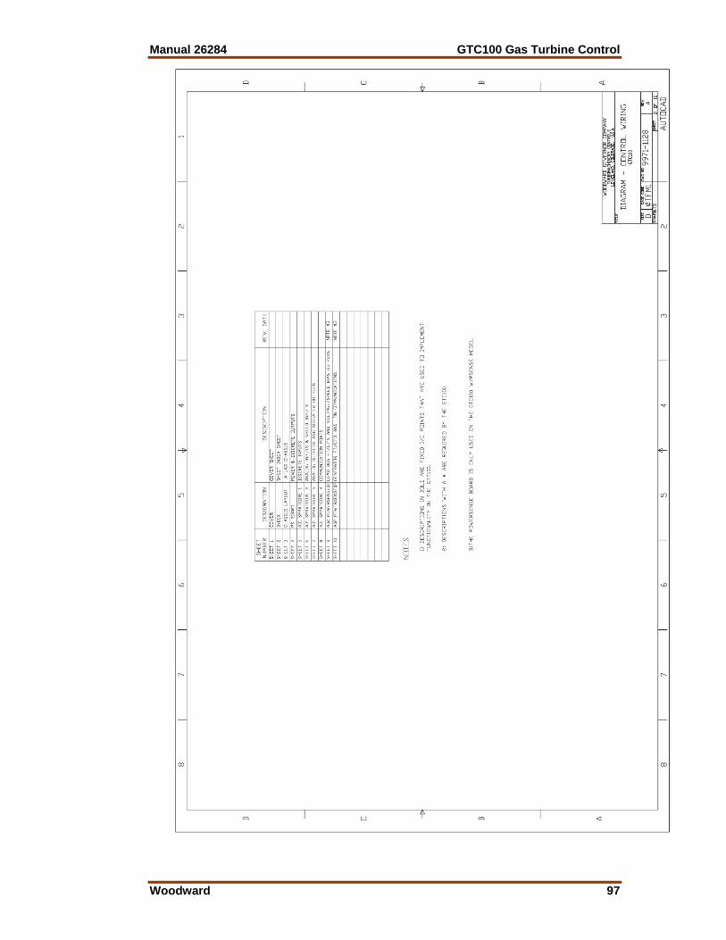
Manual 26284 GTC100 Gas Turbine Control
Woodward 97
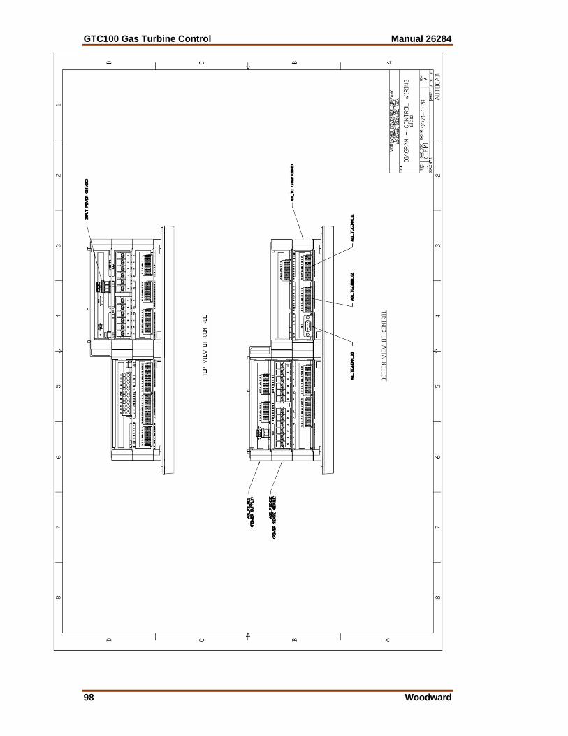
GTC100 Gas Turbine Control Manual 26284
98 Woodward
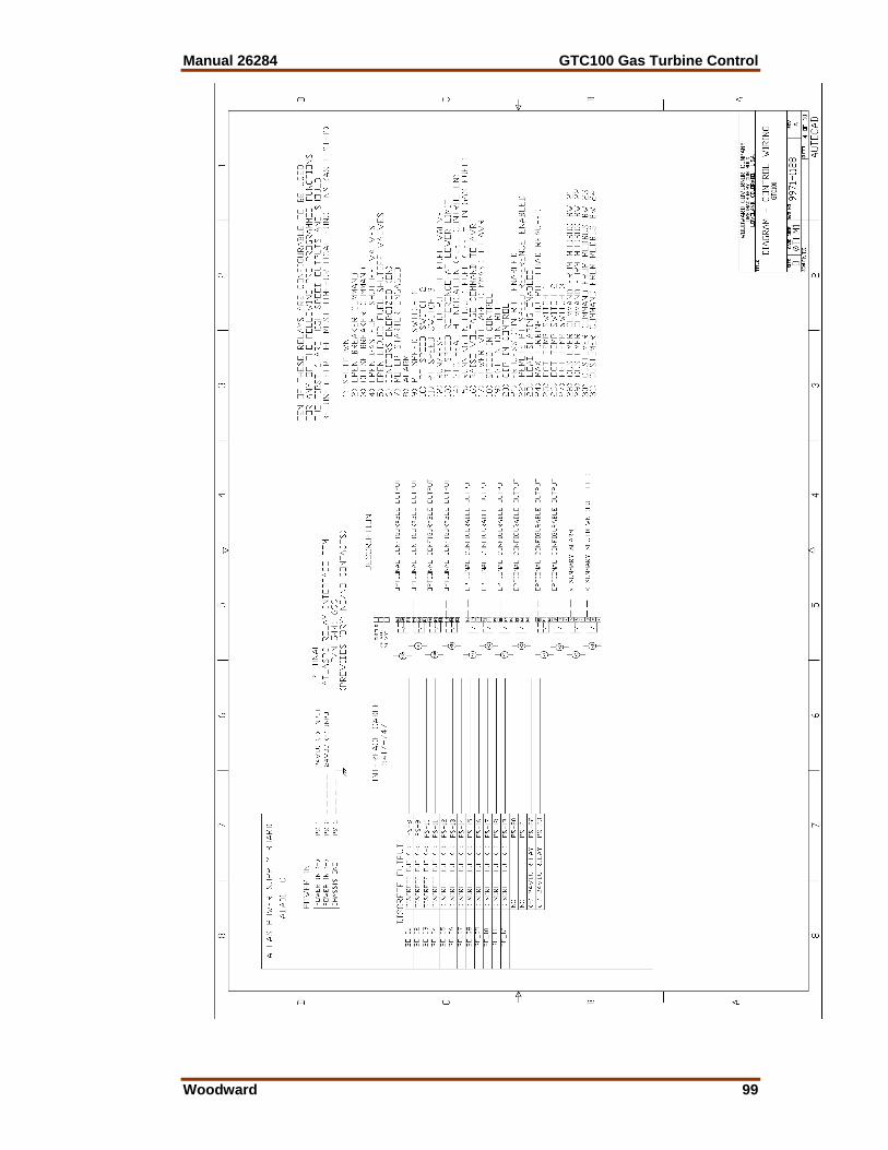
Manual 26284 GTC100 Gas Turbine Control
Woodward 99
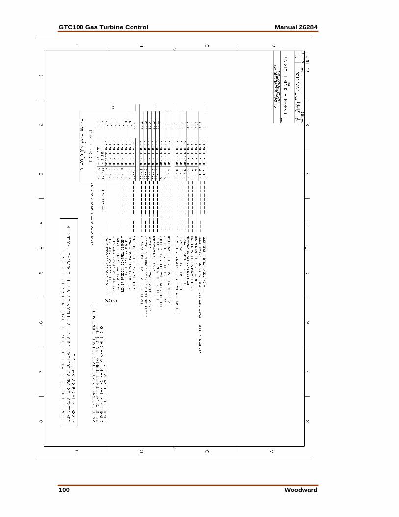
GTC100 Gas Turbine Control Manual 26284
100 Woodward
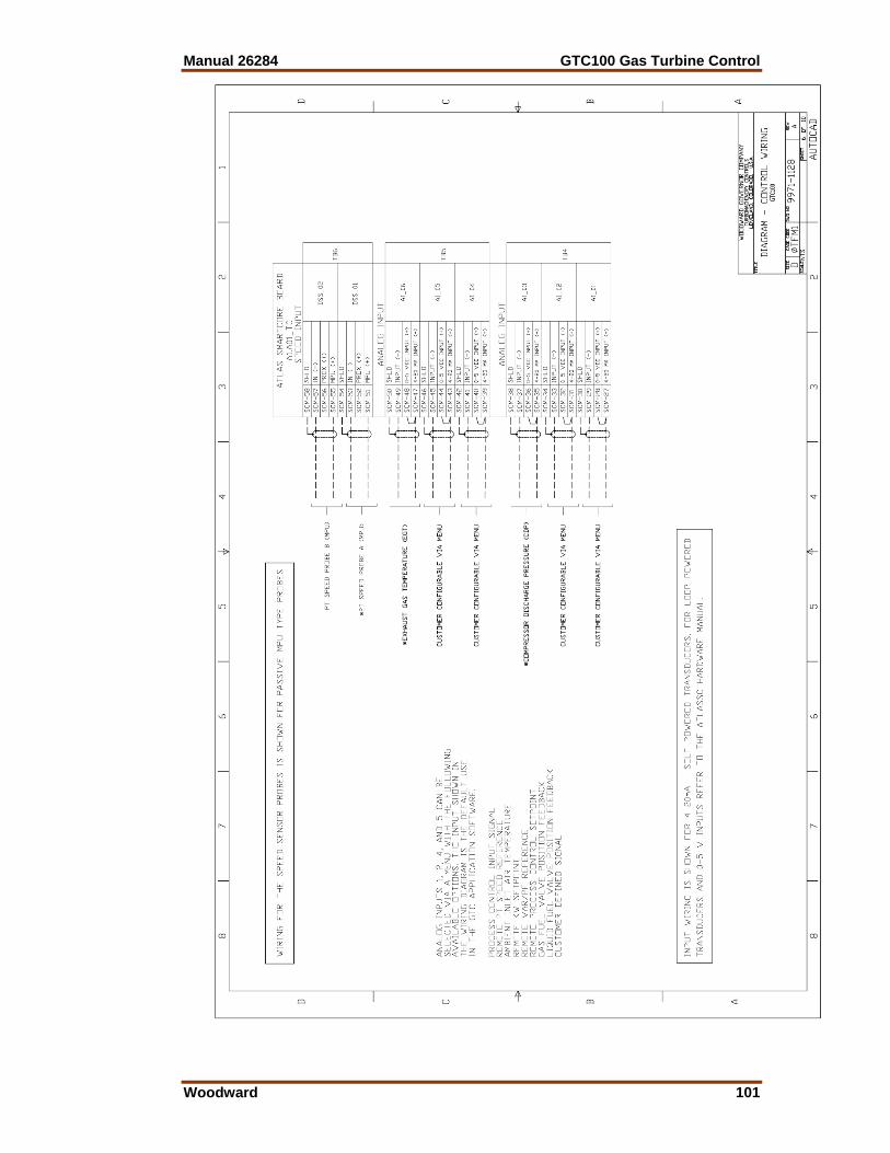
Manual 26284 GTC100 Gas Turbine Control
Woodward 101
GTC100 Gas Turbine Control Manual 26284
102 Woodward
Manual 26284 GTC100 Gas Turbine Control
Woodward 103

GTC100 Gas Turbine Control Manual 26284
104 Woodward
Manual 26284 GTC100 Gas Turbine Control
Woodward 105

GTC100 Gas Turbine Control Manual 26284
106 Woodward
Appendix B. Modbus List
The following is the Modbus List generated from the Application software. This information is sent out from the control on serial ports COM1 and COM2.
If the Communication link is lost while the unit is running, most of the functions that were enabled by the Modbus will be disabled. The start command, however, will be held in the control so that the turbine will keep running. An automated normal stop will not be available until the unit has been shut down and a reset issued to the control. The unit can always be normal-stopped manually.
WOODWARD GOVERNOR COMPANY
INDUSTRIAL CONTROLS DIVISION
FORT COLLINS, COLORADO, U.S.A.
Woodward MODBUS Slave Address Information
File created on 10/30/07
FileName: 5418-2125.C GAP
P/N: 5418-2125 REV:C
GTC100 MASTER
SINGLE SHAFT GAS TURBINE CONTROL
W/ POWERSENSE OPTION
GAP 2.18B / CODER 3.08
------------------------------------------------------------
MODBUS_S Block Name : MODBUS_COM.MOD_VAL
Boolean Writes (RPTbw)
Addr Input Description
0:0001 SHUTDOWN
0:0002 START
0:0003 RESET
0:0004 ACKNOWLEDGE
0:0005 PT SPEED LOWER
0:0006 PT SPEED RAISE
0:0007 PT FAST RATE SELECT
0:0008 PT SPEED SIGNAL OVERRIDE
0:0009 GO TO RATED SPEED / BASELOAD
0:0010 FLAME DETECTOR
0:0011 FUEL TRANSFER (TRUE = LIQ)
0:0012 ENABLE REMOTE SPEED SETPOINT
0:0013 INHIBIT SYNCHRONIZER
0:0014 GEN BREAKER AUX 52
0:0015 ENABLE LOAD SHARING
0:0016 ENABLE REACTIVE LOAD CONTROL
0:0017 LOWER VOLT/PF/VAR COMMAND
0:0018 RAISE VOLT/PF/VAR COMMAND
Manual 26284 GTC100 Gas Turbine Control
Woodward 107
0:0019 ENABLE PROCESS CONTROL
0:0020 LOWER PROCESS CONTROL SETPOINT
0:0021 RAISE PROCESS CONTROL SETPOINT
0:0022 GAS FUEL VALVE/ACTUATOR FAULT
0:0023 LIQUID FUEL VALVE/ACTUATOR FAULT
0:0024 Custom Config 24
0:0025 Enable Output Forcing Mode
0:0026 Force-Energize Output #01 Relay
0:0027 Force-Energize Output #02 Relay
0:0028 Force-Energize Output #03 Relay
0:0029 Force-Energize Output #04 Relay
0:0030 Force-Energize Output #05 Relay
0:0031 Force-Energize Output #06 Relay
0:0032 Force-Energize Output #07 Relay
0:0033 Force-Energize Output #08 Relay
0:0034 Force-Energize Output #09 Relay
0:0035 Force-Energize Output #10 Relay
0:0036 Force-Energize Output #11 Relay
0:0037 Force-Energize Output #12 Relay
0:0038 MANUAL CRANK REQUEST
0:0039 Go to Base Load Command
0:0040 ENABLE CALIBRATE MODE
0:0041 EXIT CALIBRATE MODE
0:0042 FUEL TRANSFER HOLD
0:0043 Open GEN Breaker Command
0:0044
0:0045
0:0046
0:0047
0:0048 Start Datalog File
0:0049 Stop Datalog File
0:0050 Send Datalog out Serial Port
Boolean Reads (RPTbr)
Addr Input Description
1:0001 CNFG_BI_01.BI.B_SW DI01- SHUTDOWN (CHOP FUEL)
1:0002 CNFG_BI_02.BI.B_SW DI02- START/RUN
1:0003 CNFG_BI_03.BI.B_SW DI03- SYSTEM RESET (ALM & SD)
1:0004 CNFG_BI_04.BI.B_SW DI04- SYSTEM ACKNOWLEDGE (ALM & SD)
1:0005 CNFG_BI_05.BI.B_SW DI05- PT REFERENCE LOWER
1:0006 CNFG_BI_06.BI.B_SW DI06- PT REFERENCE RAISE
1:0007 CNFG_BI_07.BI.B_SW DI07- PT REFERENCE SELECT FAST RATE
1:0008 CNFG_BI_08.BI.B_SW DI08- PT SPEED SIGNAL FAILED OVERRIDE
1:0009 CNFG_BI_09.BI.B_SW DI09- GO TO RATED SPEED / BASELOAD
1:0010 CNFG_BI_10.BI.B_SW DI10- COMBUSTOR FLAME DETECTOR
1:0011 CNFG_BI_11.BI.B_SW DI11- FUEL TRANSFER (TRUE=LIQ)
1:0012 CNFG_BI_12.BI.B_SW DI12-ENABLE REMOTE PT REF
1:0013 CNFG_BI_13.BI.B_SW DI13- INHIBIT SYNCHRONIZER
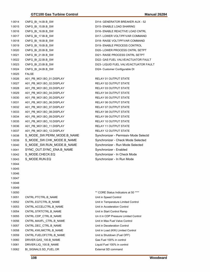
GTC100 Gas Turbine Control Manual 26284
108 Woodward
1:0014 CNFG_BI_14.BI.B_SW DI14- GENERATOR BREAKER AUX - 52
1:0015 CNFG_BI_15.BI.B_SW DI15- ENABLE LOAD SHARING
1:0016 CNFG_BI_16.BI.B_SW DI16- ENABLE REACTIVE LOAD CNTRL
1:0017 CNFG_BI_17.BI.B_SW DI17- LOWER VOLT/PF/VAR COMMAND
1:0018 CNFG_BI_18.BI.B_SW DI18- RAISE VOLT/PF/VAR COMMAND
1:0019 CNFG_BI_19.BI.B_SW DI19- ENABLE PROCESS CONTROL
1:0020 CNFG_BI_20.BI.B_SW DI20- LOWER PROCESS CNTRL SETPT
1:0021 CNFG_BI_21.BI.B_SW DI21- RAISE PROCESS CNTRL SETPT
1:0022 CNFG_BI_22.BI.B_SW DI22- GAS FUEL VALVE/ACTUATOR FAULT
1:0023 CNFG_BI_23.BI.B_SW DI23- LIQUID FUEL VALVE/ACTUATOR FAULT
1:0024 CNFG_BI_24.BI.B_SW DI24- Customer Configurable DI
1:0025 FALSE
1:0026 A01_PB_MO1.BO_01.DISPLAY RELAY 01 OUTPUT STATE
1:0027 A01_PB_MO1.BO_02.DISPLAY RELAY 02 OUTPUT STATE
1:0028 A01_PB_MO1.BO_03.DISPLAY RELAY 03 OUTPUT STATE
1:0029 A01_PB_MO1.BO_04.DISPLAY RELAY 04 OUTPUT STATE
1:0030 A01_PB_MO1.BO_05.DISPLAY RELAY 05 OUTPUT STATE
1:0031 A01_PB_MO1.BO_06.DISPLAY RELAY 06 OUTPUT STATE
1:0032 A01_PB_MO1.BO_07.DISPLAY RELAY 07 OUTPUT STATE
1:0033 A01_PB_MO1.BO_08.DISPLAY RELAY 08 OUTPUT STATE
1:0034 A01_PB_MO1.BO_09.DISPLAY RELAY 09 OUTPUT STATE
1:0035 A01_PB_MO1.BO_10.DISPLAY RELAY 10 OUTPUT STATE
1:0036 A01_PB_MO1.BO_11.DISPLAY RELAY 11 OUTPUT STATE
1:0037 A01_PB_MO1.BO_12.DISPLAY RELAY 12 OUTPUT STATE
1:0038 S_MODE_SW.PERM_MODE.B_NAME Synchronizer - Permissiv Mode Selectd
1:0039 S_MODE_SW.CHK_MODE.B_NAME Synchronizer - Check Mode Selected
1:0040 S_MODE_SW.RUN_MODE.B_NAME Synchronizer - Run Mode Selected
1:0041 SYNC_OUT.SYNC_ENA.B_NAME Synchronizer - Enabled
1:0042 S_MODE.CHECK.EQ Synchronizer - In Check Mode
1:0043 S_MODE.RUN.EQ Synchronizer - In Run Mode
1:0044
1:0045
1:0046
1:0047
1:0048
1:0049
1:0050 ** CORE Status Indicators at 50 ****
1:0051 CNTRL.PTCTRL.B_NAME Unit in Speed Control
1:0052 CNTRL.EGTCTRL.B_NAME Unit in Temperature Limited Control
1:0053 CNTRL.ACCELCTRL.B_NAME Unit in Acceleration Control
1:0054 CNTRL.STRTCTRL.B_NAME Unit in Start Control Ramp
1:0055 CNTRL.CDP_CTRL.B_NAME Un it in CDP Pressure Limited Control
1:0056 CNTRL.MAXFL_CTRL.B_NAME Unit in Max Fuel Valve Control
1:0057 CNTRL.DEC_CTRL.B_NAME Unit in Deceleration Control
1:0058 CNTRL.KWLIMCTRL.B_NAME Unit in Load (KW) Limited Control
1:0059 CNTRL.FUELOFCTRL.B_NAME Unit is Shutdown (Fuel OFF)
1:0060 DRIVER.GAS_100.B_NAME Gas Fuel 100% in control
1:0061 DRIVER.LIQ_100.B_NAME Liquid Fuel 100% in control
1:0062 BI_SIGNALS.SD_FUEL.OR External SD command
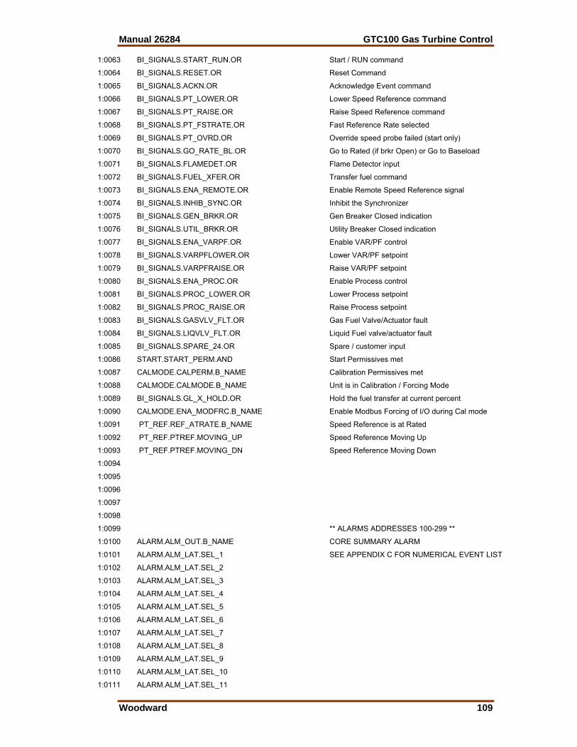
Manual 26284 GTC100 Gas Turbine Control
Woodward 109
1:0063 BI_SIGNALS.START_RUN.OR Start / RUN command
1:0064 BI_SIGNALS.RESET.OR Reset Command
1:0065 BI_SIGNALS.ACKN.OR Acknowledge Event command
1:0066 BI_SIGNALS.PT_LOWER.OR Lower Speed Reference command
1:0067 BI_SIGNALS.PT_RAISE.OR Raise Speed Reference command
1:0068 BI_SIGNALS.PT_FSTRATE.OR Fast Reference Rate selected
1:0069 BI_SIGNALS.PT_OVRD.OR Override speed probe failed (start only)
1:0070 BI_SIGNALS.GO_RATE_BL.OR Go to Rated (if brkr Open) or Go to Baseload
1:0071 BI_SIGNALS.FLAMEDET.OR Flame Detector input
1:0072 BI_SIGNALS.FUEL_XFER.OR Transfer fuel command
1:0073 BI_SIGNALS.ENA_REMOTE.OR Enable Remote Speed Reference signal
1:0074 BI_SIGNALS.INHIB_SYNC.OR Inhibit the Synchronizer
1:0075 BI_SIGNALS.GEN_BRKR.OR Gen Breaker Closed indication
1:0076 BI_SIGNALS.UTIL_BRKR.OR Utility Breaker Closed indication
1:0077 BI_SIGNALS.ENA_VARPF.OR Enable VAR/PF control
1:0078 BI_SIGNALS.VARPFLOWER.OR Lower VAR/PF setpoint
1:0079 BI_SIGNALS.VARPFRAISE.OR Raise VAR/PF setpoint
1:0080 BI_SIGNALS.ENA_PROC.OR Enable Process control
1:0081 BI_SIGNALS.PROC_LOWER.OR Lower Process setpoint
1:0082 BI_SIGNALS.PROC_RAISE.OR Raise Process setpoint
1:0083 BI_SIGNALS.GASVLV_FLT.OR Gas Fuel Valve/Actuator fault
1:0084 BI_SIGNALS.LIQVLV_FLT.OR Liquid Fuel valve/actuator fault
1:0085 BI_SIGNALS.SPARE_24.OR Spare / customer input
1:0086 START.START_PERM.AND Start Permissives met
1:0087 CALMODE.CALPERM.B_NAME Calibration Permissives met
1:0088 CALMODE.CALMODE.B_NAME Unit is in Calibration / Forcing Mode
1:0089 BI_SIGNALS.GL_X_HOLD.OR Hold the fuel transfer at current percent
1:0090 CALMODE.ENA_MODFRC.B_NAME Enable Modbus Forcing of I/O during Cal mode
1:0091 PT_REF.REF_ATRATE.B_NAME Speed Reference is at Rated
1:0092 PT_REF.PTREF.MOVING_UP Speed Reference Moving Up
1:0093 PT_REF.PTREF.MOVING_DN Speed Reference Moving Down
1:0094
1:0095
1:0096
1:0097
1:0098
1:0099 ** ALARMS ADDRESSES 100-299 **
1:0100 ALARM.ALM_OUT.B_NAME CORE SUMMARY ALARM
1:0101 ALARM.ALM_LAT.SEL_1 SEE APPENDIX C FOR NUMERICAL EVENT LIST
1:0102 ALARM.ALM_LAT.SEL_2
1:0103 ALARM.ALM_LAT.SEL_3
1:0104 ALARM.ALM_LAT.SEL_4
1:0105 ALARM.ALM_LAT.SEL_5
1:0106 ALARM.ALM_LAT.SEL_6
1:0107 ALARM.ALM_LAT.SEL_7
1:0108 ALARM.ALM_LAT.SEL_8
1:0109 ALARM.ALM_LAT.SEL_9
1:0110 ALARM.ALM_LAT.SEL_10
1:0111 ALARM.ALM_LAT.SEL_11
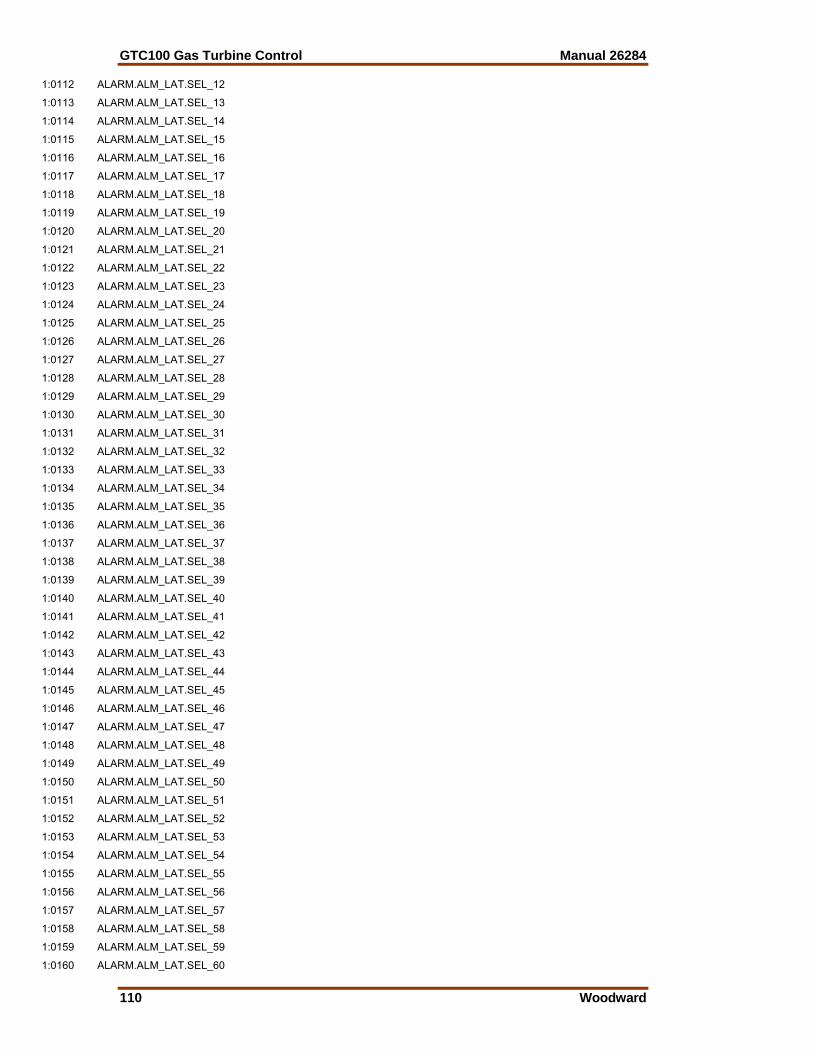
GTC100 Gas Turbine Control Manual 26284
110 Woodward
1:0112 ALARM.ALM_LAT.SEL_12
1:0113 ALARM.ALM_LAT.SEL_13
1:0114 ALARM.ALM_LAT.SEL_14
1:0115 ALARM.ALM_LAT.SEL_15
1:0116 ALARM.ALM_LAT.SEL_16
1:0117 ALARM.ALM_LAT.SEL_17
1:0118 ALARM.ALM_LAT.SEL_18
1:0119 ALARM.ALM_LAT.SEL_19
1:0120 ALARM.ALM_LAT.SEL_20
1:0121 ALARM.ALM_LAT.SEL_21
1:0122 ALARM.ALM_LAT.SEL_22
1:0123 ALARM.ALM_LAT.SEL_23
1:0124 ALARM.ALM_LAT.SEL_24
1:0125 ALARM.ALM_LAT.SEL_25
1:0126 ALARM.ALM_LAT.SEL_26
1:0127 ALARM.ALM_LAT.SEL_27
1:0128 ALARM.ALM_LAT.SEL_28
1:0129 ALARM.ALM_LAT.SEL_29
1:0130 ALARM.ALM_LAT.SEL_30
1:0131 ALARM.ALM_LAT.SEL_31
1:0132 ALARM.ALM_LAT.SEL_32
1:0133 ALARM.ALM_LAT.SEL_33
1:0134 ALARM.ALM_LAT.SEL_34
1:0135 ALARM.ALM_LAT.SEL_35
1:0136 ALARM.ALM_LAT.SEL_36
1:0137 ALARM.ALM_LAT.SEL_37
1:0138 ALARM.ALM_LAT.SEL_38
1:0139 ALARM.ALM_LAT.SEL_39
1:0140 ALARM.ALM_LAT.SEL_40
1:0141 ALARM.ALM_LAT.SEL_41
1:0142 ALARM.ALM_LAT.SEL_42
1:0143 ALARM.ALM_LAT.SEL_43
1:0144 ALARM.ALM_LAT.SEL_44
1:0145 ALARM.ALM_LAT.SEL_45
1:0146 ALARM.ALM_LAT.SEL_46
1:0147 ALARM.ALM_LAT.SEL_47
1:0148 ALARM.ALM_LAT.SEL_48
1:0149 ALARM.ALM_LAT.SEL_49
1:0150 ALARM.ALM_LAT.SEL_50
1:0151 ALARM.ALM_LAT.SEL_51
1:0152 ALARM.ALM_LAT.SEL_52
1:0153 ALARM.ALM_LAT.SEL_53
1:0154 ALARM.ALM_LAT.SEL_54
1:0155 ALARM.ALM_LAT.SEL_55
1:0156 ALARM.ALM_LAT.SEL_56
1:0157 ALARM.ALM_LAT.SEL_57
1:0158 ALARM.ALM_LAT.SEL_58
1:0159 ALARM.ALM_LAT.SEL_59
1:0160 ALARM.ALM_LAT.SEL_60

Manual 26284 GTC100 Gas Turbine Control
Woodward 111
1:0161 ALARM.ALM_LAT.SEL_61
1:0162 ALARM.ALM_LAT.SEL_62
1:0163 ALARM.ALM_LAT.SEL_63
1:0164 ALARM.ALM_LAT.SEL_64
1:0165 ALARM.ALM_LAT.SEL_65
1:0166 ALARM.ALM_LAT.SEL_66
1:0167 ALARM.ALM_LAT.SEL_67
1:0168 ALARM.ALM_LAT.SEL_68
1:0169 ALARM.ALM_LAT.SEL_69
1:0170 ALARM.ALM_LAT.SEL_70
1:0171 ALARM.ALM_LAT.SEL_71
1:0172 ALARM.ALM_LAT.SEL_72
1:0173 ALARM.ALM_LAT.SEL_73
1:0174 ALARM.ALM_LAT.SEL_74
1:0175 ALARM.ALM_LAT.SEL_75
1:0176 ALARM.ALM_LAT.SEL_76
1:0177 ALARM.ALM_LAT.SEL_77
1:0178 ALARM.ALM_LAT.SEL_78
1:0179 ALARM.ALM_LAT.SEL_79
1:0180 ALARM.ALM_LAT.SEL_80
1:0181 ALARM.ALM_LAT.SEL_81
1:0182 ALARM.ALM_LAT.SEL_82
1:0183 ALARM.ALM_LAT.SEL_83
1:0184 ALARM.ALM_LAT.SEL_84
1:0185 ALARM.ALM_LAT.SEL_85
1:0186 ALARM.ALM_LAT.SEL_86
1:0187 ALARM.ALM_LAT.SEL_87
1:0188 ALARM.ALM_LAT.SEL_88
1:0189 ALARM.ALM_LAT.SEL_89
1:0190 ALARM.ALM_LAT.SEL_90
1:0191 ALARM.ALM_LAT.SEL_91
1:0192 ALARM.ALM_LAT.SEL_92
1:0193 ALARM.ALM_LAT.SEL_93
1:0194 ALARM.ALM_LAT.SEL_94
1:0195 ALARM.ALM_LAT.SEL_95
1:0196 ALARM.ALM_LAT.SEL_96
1:0197 ALARM.ALM_LAT.SEL_97
1:0198 ALARM.ALM_LAT.SEL_98
1:0199 ALARM.ALM_LAT.SEL_99
1:0200 ALARM.ALM_LAT.SEL_100
1:0201 ALARM.ALM_LAT.SEL_101
1:0202 ALARM.ALM_LAT.SEL_102
1:0203 ALARM.ALM_LAT.SEL_103
1:0204 ALARM.ALM_LAT.SEL_104
1:0205 ALARM.ALM_LAT.SEL_105
1:0206 ALARM.ALM_LAT.SEL_106
1:0207 ALARM.ALM_LAT.SEL_107
1:0208 ALARM.ALM_LAT.SEL_108
1:0209 ALARM.ALM_LAT.SEL_109
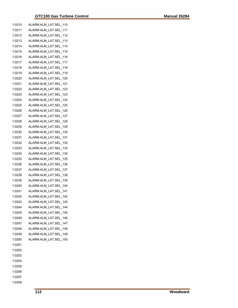
GTC100 Gas Turbine Control Manual 26284
112 Woodward
1:0210 ALARM.ALM_LAT.SEL_110
1:0211 ALARM.ALM_LAT.SEL_111
1:0212 ALARM.ALM_LAT.SEL_112
1:0213 ALARM.ALM_LAT.SEL_113
1:0214 ALARM.ALM_LAT.SEL_114
1:0215 ALARM.ALM_LAT.SEL_115
1:0216 ALARM.ALM_LAT.SEL_116
1:0217 ALARM.ALM_LAT.SEL_117
1:0218 ALARM.ALM_LAT.SEL_118
1:0219 ALARM.ALM_LAT.SEL_119
1:0220 ALARM.ALM_LAT.SEL_120
1:0221 ALARM.ALM_LAT.SEL_121
1:0222 ALARM.ALM_LAT.SEL_122
1:0223 ALARM.ALM_LAT.SEL_123
1:0224 ALARM.ALM_LAT.SEL_124
1:0225 ALARM.ALM_LAT.SEL_125
1:0226 ALARM.ALM_LAT.SEL_126
1:0227 ALARM.ALM_LAT.SEL_127
1:0228 ALARM.ALM_LAT.SEL_128
1:0229 ALARM.ALM_LAT.SEL_129
1:0230 ALARM.ALM_LAT.SEL_130
1:0231 ALARM.ALM_LAT.SEL_131
1:0232 ALARM.ALM_LAT.SEL_132
1:0233 ALARM.ALM_LAT.SEL_133
1:0234 ALARM.ALM_LAT.SEL_134
1:0235 ALARM.ALM_LAT.SEL_135
1:0236 ALARM.ALM_LAT.SEL_136
1:0237 ALARM.ALM_LAT.SEL_137
1:0238 ALARM.ALM_LAT.SEL_138
1:0239 ALARM.ALM_LAT.SEL_139
1:0240 ALARM.ALM_LAT.SEL_140
1:0241 ALARM.ALM_LAT.SEL_141
1:0242 ALARM.ALM_LAT.SEL_142
1:0243 ALARM.ALM_LAT.SEL_143
1:0244 ALARM.ALM_LAT.SEL_144
1:0245 ALARM.ALM_LAT.SEL_145
1:0246 ALARM.ALM_LAT.SEL_146
1:0247 ALARM.ALM_LAT.SEL_147
1:0248 ALARM.ALM_LAT.SEL_148
1:0249 ALARM.ALM_LAT.SEL_149
1:0250 ALARM.ALM_LAT.SEL_150
1:0251
1:0252
1:0253
1:0254
1:0255
1:0256
1:0257
1:0258
Manual 26284 GTC100 Gas Turbine Control
Woodward 113
1:0259
1:0260
1:0261
1:0262
1:0263
1:0264
1:0265
1:0266
1:0267
1:0268
1:0269
1:0270
1:0271
1:0272
1:0273
1:0274
1:0275
1:0276
1:0277
1:0278
1:0279
1:0280
1:0281
1:0282
1:0283
1:0284
1:0285
1:0286
1:0287
1:0288
1:0289
1:0290
1:0291
1:0292
1:0293
1:0294
1:0295
1:0296
1:0297
1:0298
1:0299 ** SOFT SD ADDRESSES 300-499 **
1:0300 SHUTDOWN.SOFTSD_LAT.LATCH1 SUMMARY OF SOFT SD LATCH
1:0301 SHUTDOWN.SOFTSD_LAT.SEL_1
1:0302 SHUTDOWN.SOFTSD_LAT.SEL_2
1:0303 SHUTDOWN.SOFTSD_LAT.SEL_3
1:0304 SHUTDOWN.SOFTSD_LAT.SEL_4
1:0305 SHUTDOWN.SOFTSD_LAT.SEL_5
1:0306 SHUTDOWN.SOFTSD_LAT.SEL_6
1:0307 SHUTDOWN.SOFTSD_LAT.SEL_7
GTC100 Gas Turbine Control Manual 26284
114 Woodward
1:0308 SHUTDOWN.SOFTSD_LAT.SEL_8
1:0309 SHUTDOWN.SOFTSD_LAT.SEL_9
1:0310 SHUTDOWN.SOFTSD_LAT.SEL_10
1:0311 SHUTDOWN.SOFTSD_LAT.SEL_11
1:0312 SHUTDOWN.SOFTSD_LAT.SEL_12
1:0313 SHUTDOWN.SOFTSD_LAT.SEL_13
1:0314 SHUTDOWN.SOFTSD_LAT.SEL_14
1:0315 SHUTDOWN.SOFTSD_LAT.SEL_15
1:0316 SHUTDOWN.SOFTSD_LAT.SEL_16
1:0317 SHUTDOWN.SOFTSD_LAT.SEL_17
1:0318 SHUTDOWN.SOFTSD_LAT.SEL_18
1:0319 SHUTDOWN.SOFTSD_LAT.SEL_19
1:0320 SHUTDOWN.SOFTSD_LAT.SEL_20
1:0321 SHUTDOWN.SOFTSD_LAT.SEL_21
1:0322 SHUTDOWN.SOFTSD_LAT.SEL_22
1:0323 SHUTDOWN.SOFTSD_LAT.SEL_23
1:0324 SHUTDOWN.SOFTSD_LAT.SEL_24
1:0325 SHUTDOWN.SOFTSD_LAT.SEL_25
1:0326 SHUTDOWN.SOFTSD_LAT.SEL_26
1:0327 SHUTDOWN.SOFTSD_LAT.SEL_27
1:0328 SHUTDOWN.SOFTSD_LAT.SEL_28
1:0329 SHUTDOWN.SOFTSD_LAT.SEL_29
1:0330 SHUTDOWN.SOFTSD_LAT.SEL_30
1:0331 SHUTDOWN.SOFTSD_LAT.SEL_31
1:0332 SHUTDOWN.SOFTSD_LAT.SEL_32
1:0333 SHUTDOWN.SOFTSD_LAT.SEL_33
1:0334 SHUTDOWN.SOFTSD_LAT.SEL_34
1:0335 SHUTDOWN.SOFTSD_LAT.SEL_35
1:0336 SHUTDOWN.SOFTSD_LAT.SEL_36
1:0337 SHUTDOWN.SOFTSD_LAT.SEL_37
1:0338 SHUTDOWN.SOFTSD_LAT.SEL_38
1:0339 SHUTDOWN.SOFTSD_LAT.SEL_39
1:0340 SHUTDOWN.SOFTSD_LAT.SEL_40
1:0341 SHUTDOWN.SOFTSD_LAT.SEL_41
1:0342 SHUTDOWN.SOFTSD_LAT.SEL_42
1:0343 SHUTDOWN.SOFTSD_LAT.SEL_43
1:0344 SHUTDOWN.SOFTSD_LAT.SEL_44
1:0345 SHUTDOWN.SOFTSD_LAT.SEL_45
1:0346 SHUTDOWN.SOFTSD_LAT.SEL_46
1:0347 SHUTDOWN.SOFTSD_LAT.SEL_47
1:0348 SHUTDOWN.SOFTSD_LAT.SEL_48
1:0349 SHUTDOWN.SOFTSD_LAT.SEL_49
1:0350 SHUTDOWN.SOFTSD_LAT.SEL_50
1:0351 SHUTDOWN.SOFTSD_LAT.SEL_51
1:0352 SHUTDOWN.SOFTSD_LAT.SEL_52
1:0353 SHUTDOWN.SOFTSD_LAT.SEL_53
1:0354 SHUTDOWN.SOFTSD_LAT.SEL_54
1:0355 SHUTDOWN.SOFTSD_LAT.SEL_55
1:0356 SHUTDOWN.SOFTSD_LAT.SEL_56

Manual 26284 GTC100 Gas Turbine Control
Woodward 115
1:0357 SHUTDOWN.SOFTSD_LAT.SEL_57
1:0358 SHUTDOWN.SOFTSD_LAT.SEL_58
1:0359 SHUTDOWN.SOFTSD_LAT.SEL_59
1:0360 SHUTDOWN.SOFTSD_LAT.SEL_60
1:0361 SHUTDOWN.SOFTSD_LAT.SEL_61
1:0362 SHUTDOWN.SOFTSD_LAT.SEL_62
1:0363 SHUTDOWN.SOFTSD_LAT.SEL_63
1:0364 SHUTDOWN.SOFTSD_LAT.SEL_64
1:0365 SHUTDOWN.SOFTSD_LAT.SEL_65
1:0366 SHUTDOWN.SOFTSD_LAT.SEL_66
1:0367 SHUTDOWN.SOFTSD_LAT.SEL_67
1:0368 SHUTDOWN.SOFTSD_LAT.SEL_68
1:0369 SHUTDOWN.SOFTSD_LAT.SEL_69
1:0370 SHUTDOWN.SOFTSD_LAT.SEL_70
1:0371 SHUTDOWN.SOFTSD_LAT.SEL_71
1:0372 SHUTDOWN.SOFTSD_LAT.SEL_72
1:0373 SHUTDOWN.SOFTSD_LAT.SEL_73
1:0374 SHUTDOWN.SOFTSD_LAT.SEL_74
1:0375 SHUTDOWN.SOFTSD_LAT.SEL_75
1:0376 SHUTDOWN.SOFTSD_LAT.SEL_76
1:0377 SHUTDOWN.SOFTSD_LAT.SEL_77
1:0378 SHUTDOWN.SOFTSD_LAT.SEL_78
1:0379 SHUTDOWN.SOFTSD_LAT.SEL_79
1:0380 SHUTDOWN.SOFTSD_LAT.SEL_80
1:0381 SHUTDOWN.SOFTSD_LAT.SEL_81
1:0382 SHUTDOWN.SOFTSD_LAT.SEL_82
1:0383 SHUTDOWN.SOFTSD_LAT.SEL_83
1:0384 SHUTDOWN.SOFTSD_LAT.SEL_84
1:0385 SHUTDOWN.SOFTSD_LAT.SEL_85
1:0386 SHUTDOWN.SOFTSD_LAT.SEL_86
1:0387 SHUTDOWN.SOFTSD_LAT.SEL_87
1:0388 SHUTDOWN.SOFTSD_LAT.SEL_88
1:0389 SHUTDOWN.SOFTSD_LAT.SEL_89
1:0390 SHUTDOWN.SOFTSD_LAT.SEL_90
1:0391 SHUTDOWN.SOFTSD_LAT.SEL_91
1:0392 SHUTDOWN.SOFTSD_LAT.SEL_92
1:0393 SHUTDOWN.SOFTSD_LAT.SEL_93
1:0394 SHUTDOWN.SOFTSD_LAT.SEL_94
1:0395 SHUTDOWN.SOFTSD_LAT.SEL_95
1:0396 SHUTDOWN.SOFTSD_LAT.SEL_96
1:0397 SHUTDOWN.SOFTSD_LAT.SEL_97
1:0398 SHUTDOWN.SOFTSD_LAT.SEL_98
1:0399 SHUTDOWN.SOFTSD_LAT.SEL_99
1:0400 SHUTDOWN.SOFTSD_LAT.SEL_100
1:0401 SHUTDOWN.SOFTSD_LAT.SEL_101
1:0402 SHUTDOWN.SOFTSD_LAT.SEL_102
1:0403 SHUTDOWN.SOFTSD_LAT.SEL_103
1:0404 SHUTDOWN.SOFTSD_LAT.SEL_104
1:0405 SHUTDOWN.SOFTSD_LAT.SEL_105
GTC100 Gas Turbine Control Manual 26284
116 Woodward
1:0406 SHUTDOWN.SOFTSD_LAT.SEL_106
1:0407 SHUTDOWN.SOFTSD_LAT.SEL_107
1:0408 SHUTDOWN.SOFTSD_LAT.SEL_108
1:0409 SHUTDOWN.SOFTSD_LAT.SEL_109
1:0410 SHUTDOWN.SOFTSD_LAT.SEL_110
1:0411 SHUTDOWN.SOFTSD_LAT.SEL_111
1:0412 SHUTDOWN.SOFTSD_LAT.SEL_112
1:0413 SHUTDOWN.SOFTSD_LAT.SEL_113
1:0414 SHUTDOWN.SOFTSD_LAT.SEL_114
1:0415 SHUTDOWN.SOFTSD_LAT.SEL_115
1:0416 SHUTDOWN.SOFTSD_LAT.SEL_116
1:0417 SHUTDOWN.SOFTSD_LAT.SEL_117
1:0418 SHUTDOWN.SOFTSD_LAT.SEL_118
1:0419 SHUTDOWN.SOFTSD_LAT.SEL_119
1:0420 SHUTDOWN.SOFTSD_LAT.SEL_120
1:0421 SHUTDOWN.SOFTSD_LAT.SEL_121
1:0422 SHUTDOWN.SOFTSD_LAT.SEL_122
1:0423 SHUTDOWN.SOFTSD_LAT.SEL_123
1:0424 SHUTDOWN.SOFTSD_LAT.SEL_124
1:0425 SHUTDOWN.SOFTSD_LAT.SEL_125
1:0426 SHUTDOWN.SOFTSD_LAT.SEL_126
1:0427 SHUTDOWN.SOFTSD_LAT.SEL_127
1:0428 SHUTDOWN.SOFTSD_LAT.SEL_128
1:0429 SHUTDOWN.SOFTSD_LAT.SEL_129
1:0430 SHUTDOWN.SOFTSD_LAT.SEL_130
1:0431 SHUTDOWN.SOFTSD_LAT.SEL_131
1:0432 SHUTDOWN.SOFTSD_LAT.SEL_132
1:0433 SHUTDOWN.SOFTSD_LAT.SEL_133
1:0434 SHUTDOWN.SOFTSD_LAT.SEL_134
1:0435 SHUTDOWN.SOFTSD_LAT.SEL_135
1:0436 SHUTDOWN.SOFTSD_LAT.SEL_136
1:0437 SHUTDOWN.SOFTSD_LAT.SEL_137
1:0438 SHUTDOWN.SOFTSD_LAT.SEL_138
1:0439 SHUTDOWN.SOFTSD_LAT.SEL_139
1:0440 SHUTDOWN.SOFTSD_LAT.SEL_140
1:0441 SHUTDOWN.SOFTSD_LAT.SEL_141
1:0442 SHUTDOWN.SOFTSD_LAT.SEL_142
1:0443 SHUTDOWN.SOFTSD_LAT.SEL_143
1:0444 SHUTDOWN.SOFTSD_LAT.SEL_144
1:0445 SHUTDOWN.SOFTSD_LAT.SEL_145
1:0446 SHUTDOWN.SOFTSD_LAT.SEL_146
1:0447 SHUTDOWN.SOFTSD_LAT.SEL_147
1:0448 SHUTDOWN.SOFTSD_LAT.SEL_148
1:0449 SHUTDOWN.SOFTSD_LAT.SEL_149
1:0450 SHUTDOWN.SOFTSD_LAT.SEL_150
1:0451
1:0452
1:0453
1:0454

Manual 26284 GTC100 Gas Turbine Control
Woodward 117
1:0455
1:0456
1:0457
1:0458
1:0459
1:0460
1:0461
1:0462
1:0463
1:0464
1:0465
1:0466
1:0467
1:0468
1:0469
1:0470
1:0471
1:0472
1:0473
1:0474
1:0475
1:0476
1:0477
1:0478
1:0479
1:0480
1:0481
1:0482
1:0483
1:0484
1:0485
1:0486
1:0487
1:0488
1:0489
1:0490
1:0491
1:0492
1:0493
1:0494
1:0495
1:0496
1:0497
1:0498
1:0499 ** HARD SD ADDRESSES 500-699 **
1:0500 SHUTDOWN.HARDSD_LAT.LATCH1 SUMMARY HARD SD (FUEL CHOP)
1:0501 SHUTDOWN.HARDSD_LAT.SEL_1
1:0502 SHUTDOWN.HARDSD_LAT.SEL_2
1:0503 SHUTDOWN.HARDSD_LAT.SEL_3
GTC100 Gas Turbine Control Manual 26284
118 Woodward
1:0504 SHUTDOWN.HARDSD_LAT.SEL_4
1:0505 SHUTDOWN.HARDSD_LAT.SEL_5
1:0506 SHUTDOWN.HARDSD_LAT.SEL_6
1:0507 SHUTDOWN.HARDSD_LAT.SEL_7
1:0508 SHUTDOWN.HARDSD_LAT.SEL_8
1:0509 SHUTDOWN.HARDSD_LAT.SEL_9
1:0510 SHUTDOWN.HARDSD_LAT.SEL_10
1:0511 SHUTDOWN.HARDSD_LAT.SEL_11
1:0512 SHUTDOWN.HARDSD_LAT.SEL_12
1:0513 SHUTDOWN.HARDSD_LAT.SEL_13
1:0514 SHUTDOWN.HARDSD_LAT.SEL_14
1:0515 SHUTDOWN.HARDSD_LAT.SEL_15
1:0516 SHUTDOWN.HARDSD_LAT.SEL_16
1:0517 SHUTDOWN.HARDSD_LAT.SEL_17
1:0518 SHUTDOWN.HARDSD_LAT.SEL_18
1:0519 SHUTDOWN.HARDSD_LAT.SEL_19
1:0520 SHUTDOWN.HARDSD_LAT.SEL_20
1:0521 SHUTDOWN.HARDSD_LAT.SEL_21
1:0522 SHUTDOWN.HARDSD_LAT.SEL_22
1:0523 SHUTDOWN.HARDSD_LAT.SEL_23
1:0524 SHUTDOWN.HARDSD_LAT.SEL_24
1:0525 SHUTDOWN.HARDSD_LAT.SEL_25
1:0526 SHUTDOWN.HARDSD_LAT.SEL_26
1:0527 SHUTDOWN.HARDSD_LAT.SEL_27
1:0528 SHUTDOWN.HARDSD_LAT.SEL_28
1:0529 SHUTDOWN.HARDSD_LAT.SEL_29
1:0530 SHUTDOWN.HARDSD_LAT.SEL_30
1:0531 SHUTDOWN.HARDSD_LAT.SEL_31
1:0532 SHUTDOWN.HARDSD_LAT.SEL_32
1:0533 SHUTDOWN.HARDSD_LAT.SEL_33
1:0534 SHUTDOWN.HARDSD_LAT.SEL_34
1:0535 SHUTDOWN.HARDSD_LAT.SEL_35
1:0536 SHUTDOWN.HARDSD_LAT.SEL_36
1:0537 SHUTDOWN.HARDSD_LAT.SEL_37
1:0538 SHUTDOWN.HARDSD_LAT.SEL_38
1:0539 SHUTDOWN.HARDSD_LAT.SEL_39
1:0540 SHUTDOWN.HARDSD_LAT.SEL_40
1:0541 SHUTDOWN.HARDSD_LAT.SEL_41
1:0542 SHUTDOWN.HARDSD_LAT.SEL_42
1:0543 SHUTDOWN.HARDSD_LAT.SEL_43
1:0544 SHUTDOWN.HARDSD_LAT.SEL_44
1:0545 SHUTDOWN.HARDSD_LAT.SEL_45
1:0546 SHUTDOWN.HARDSD_LAT.SEL_46
1:0547 SHUTDOWN.HARDSD_LAT.SEL_47
1:0548 SHUTDOWN.HARDSD_LAT.SEL_48
1:0549 SHUTDOWN.HARDSD_LAT.SEL_49
1:0550 SHUTDOWN.HARDSD_LAT.SEL_50
1:0551 SHUTDOWN.HARDSD_LAT.SEL_51
1:0552 SHUTDOWN.HARDSD_LAT.SEL_52
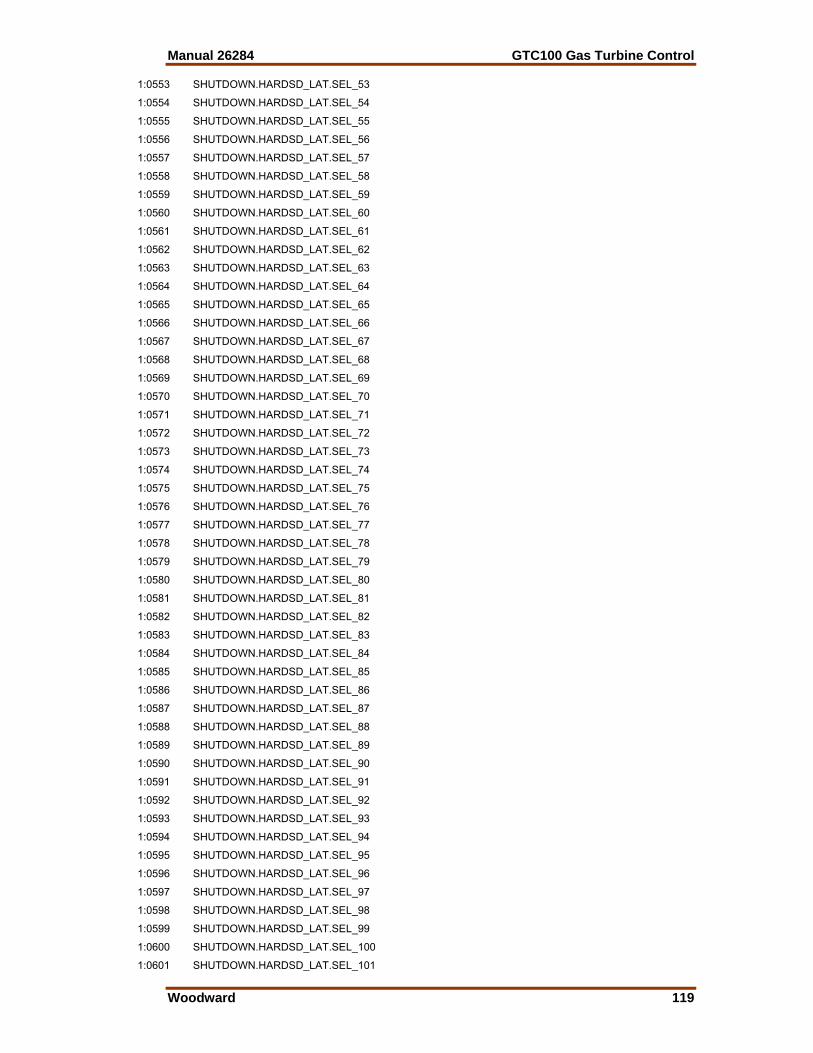
Manual 26284 GTC100 Gas Turbine Control
Woodward 119
1:0553 SHUTDOWN.HARDSD_LAT.SEL_53
1:0554 SHUTDOWN.HARDSD_LAT.SEL_54
1:0555 SHUTDOWN.HARDSD_LAT.SEL_55
1:0556 SHUTDOWN.HARDSD_LAT.SEL_56
1:0557 SHUTDOWN.HARDSD_LAT.SEL_57
1:0558 SHUTDOWN.HARDSD_LAT.SEL_58
1:0559 SHUTDOWN.HARDSD_LAT.SEL_59
1:0560 SHUTDOWN.HARDSD_LAT.SEL_60
1:0561 SHUTDOWN.HARDSD_LAT.SEL_61
1:0562 SHUTDOWN.HARDSD_LAT.SEL_62
1:0563 SHUTDOWN.HARDSD_LAT.SEL_63
1:0564 SHUTDOWN.HARDSD_LAT.SEL_64
1:0565 SHUTDOWN.HARDSD_LAT.SEL_65
1:0566 SHUTDOWN.HARDSD_LAT.SEL_66
1:0567 SHUTDOWN.HARDSD_LAT.SEL_67
1:0568 SHUTDOWN.HARDSD_LAT.SEL_68
1:0569 SHUTDOWN.HARDSD_LAT.SEL_69
1:0570 SHUTDOWN.HARDSD_LAT.SEL_70
1:0571 SHUTDOWN.HARDSD_LAT.SEL_71
1:0572 SHUTDOWN.HARDSD_LAT.SEL_72
1:0573 SHUTDOWN.HARDSD_LAT.SEL_73
1:0574 SHUTDOWN.HARDSD_LAT.SEL_74
1:0575 SHUTDOWN.HARDSD_LAT.SEL_75
1:0576 SHUTDOWN.HARDSD_LAT.SEL_76
1:0577 SHUTDOWN.HARDSD_LAT.SEL_77
1:0578 SHUTDOWN.HARDSD_LAT.SEL_78
1:0579 SHUTDOWN.HARDSD_LAT.SEL_79
1:0580 SHUTDOWN.HARDSD_LAT.SEL_80
1:0581 SHUTDOWN.HARDSD_LAT.SEL_81
1:0582 SHUTDOWN.HARDSD_LAT.SEL_82
1:0583 SHUTDOWN.HARDSD_LAT.SEL_83
1:0584 SHUTDOWN.HARDSD_LAT.SEL_84
1:0585 SHUTDOWN.HARDSD_LAT.SEL_85
1:0586 SHUTDOWN.HARDSD_LAT.SEL_86
1:0587 SHUTDOWN.HARDSD_LAT.SEL_87
1:0588 SHUTDOWN.HARDSD_LAT.SEL_88
1:0589 SHUTDOWN.HARDSD_LAT.SEL_89
1:0590 SHUTDOWN.HARDSD_LAT.SEL_90
1:0591 SHUTDOWN.HARDSD_LAT.SEL_91
1:0592 SHUTDOWN.HARDSD_LAT.SEL_92
1:0593 SHUTDOWN.HARDSD_LAT.SEL_93
1:0594 SHUTDOWN.HARDSD_LAT.SEL_94
1:0595 SHUTDOWN.HARDSD_LAT.SEL_95
1:0596 SHUTDOWN.HARDSD_LAT.SEL_96
1:0597 SHUTDOWN.HARDSD_LAT.SEL_97
1:0598 SHUTDOWN.HARDSD_LAT.SEL_98
1:0599 SHUTDOWN.HARDSD_LAT.SEL_99
1:0600 SHUTDOWN.HARDSD_LAT.SEL_100
1:0601 SHUTDOWN.HARDSD_LAT.SEL_101

GTC100 Gas Turbine Control Manual 26284
120 Woodward
1:0602 SHUTDOWN.HARDSD_LAT.SEL_102
1:0603 SHUTDOWN.HARDSD_LAT.SEL_103
1:0604 SHUTDOWN.HARDSD_LAT.SEL_104
1:0605 SHUTDOWN.HARDSD_LAT.SEL_105
1:0606 SHUTDOWN.HARDSD_LAT.SEL_106
1:0607 SHUTDOWN.HARDSD_LAT.SEL_107
1:0608 SHUTDOWN.HARDSD_LAT.SEL_108
1:0609 SHUTDOWN.HARDSD_LAT.SEL_109
1:0610 SHUTDOWN.HARDSD_LAT.SEL_110
1:0611 SHUTDOWN.HARDSD_LAT.SEL_111
1:0612 SHUTDOWN.HARDSD_LAT.SEL_112
1:0613 SHUTDOWN.HARDSD_LAT.SEL_113
1:0614 SHUTDOWN.HARDSD_LAT.SEL_114
1:0615 SHUTDOWN.HARDSD_LAT.SEL_115
1:0616 SHUTDOWN.HARDSD_LAT.SEL_116
1:0617 SHUTDOWN.HARDSD_LAT.SEL_117
1:0618 SHUTDOWN.HARDSD_LAT.SEL_118
1:0619 SHUTDOWN.HARDSD_LAT.SEL_119
1:0620 SHUTDOWN.HARDSD_LAT.SEL_120
1:0621 SHUTDOWN.HARDSD_LAT.SEL_121
1:0622 SHUTDOWN.HARDSD_LAT.SEL_122
1:0623 SHUTDOWN.HARDSD_LAT.SEL_123
1:0624 SHUTDOWN.HARDSD_LAT.SEL_124
1:0625 SHUTDOWN.HARDSD_LAT.SEL_125
1:0626 SHUTDOWN.HARDSD_LAT.SEL_126
1:0627 SHUTDOWN.HARDSD_LAT.SEL_127
1:0628 SHUTDOWN.HARDSD_LAT.SEL_128
1:0629 SHUTDOWN.HARDSD_LAT.SEL_129
1:0630 SHUTDOWN.HARDSD_LAT.SEL_130
1:0631 SHUTDOWN.HARDSD_LAT.SEL_131
1:0632 SHUTDOWN.HARDSD_LAT.SEL_132
1:0633 SHUTDOWN.HARDSD_LAT.SEL_133
1:0634 SHUTDOWN.HARDSD_LAT.SEL_134
1:0635 SHUTDOWN.HARDSD_LAT.SEL_135
1:0636 SHUTDOWN.HARDSD_LAT.SEL_136
1:0637 SHUTDOWN.HARDSD_LAT.SEL_137
1:0638 SHUTDOWN.HARDSD_LAT.SEL_138
1:0639 SHUTDOWN.HARDSD_LAT.SEL_139
1:0640 SHUTDOWN.HARDSD_LAT.SEL_140
1:0641 SHUTDOWN.HARDSD_LAT.SEL_141
1:0642 SHUTDOWN.HARDSD_LAT.SEL_142
1:0643 SHUTDOWN.HARDSD_LAT.SEL_143
1:0644 SHUTDOWN.HARDSD_LAT.SEL_144
1:0645 SHUTDOWN.HARDSD_LAT.SEL_145
1:0646 SHUTDOWN.HARDSD_LAT.SEL_146
1:0647 SHUTDOWN.HARDSD_LAT.SEL_147
1:0648 SHUTDOWN.HARDSD_LAT.SEL_148
1:0649 SHUTDOWN.HARDSD_LAT.SEL_149
1:0650 SHUTDOWN.HARDSD_LAT.SEL_150
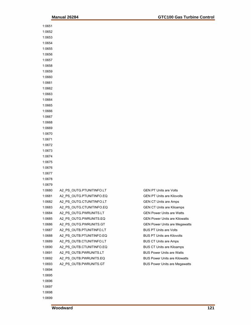
Manual 26284 GTC100 Gas Turbine Control
Woodward 121
1:0651
1:0652
1:0653
1:0654
1:0655
1:0656
1:0657
1:0658
1:0659
1:0660
1:0661
1:0662
1:0663
1:0664
1:0665
1:0666
1:0667
1:0668
1:0669
1:0670
1:0671
1:0672
1:0673
1:0674
1:0675
1:0676
1:0677
1:0678
1:0679
1:0680 A2_PS_OUTG.PTUNITINFO.LT GEN PT Units are Volts
1:0681 A2_PS_OUTG.PTUNITINFO.EQ GEN PT Units are Kilovolts
1:0682 A2_PS_OUTG.CTUNITINFO.LT GEN CT Units are Amps
1:0683 A2_PS_OUTG.CTUNITINFO.EQ GEN CT Units are Kiloamps
1:0684 A2_PS_OUTG.PWRUNITS.LT GEN Power Units are Watts
1:0685 A2_PS_OUTG.PWRUNITS.EQ GEN Power Units are Kilowatts
1:0686 A2_PS_OUTG.PWRUNITS.GT GEN Power Units are Megawatts
1:0687 A2_PS_OUTB.PTUNITINFO.LT BUS PT Units are Volts
1:0688 A2_PS_OUTB.PTUNITINFO.EQ BUS PT Units are Kilovolts
1:0689 A2_PS_OUTB.CTUNITINFO.LT BUS CT Units are Amps
1:0690 A2_PS_OUTB.CTUNITINFO.EQ BUS CT Units are Kiloamps
1:0691 A2_PS_OUTB.PWRUNITS.LT BUS Power Units are Watts
1:0692 A2_PS_OUTB.PWRUNITS.EQ BUS Power Units are Kilowatts
1:0693 A2_PS_OUTB.PWRUNITS.GT BUS Power Units are Megawatts
1:0694
1:0695
1:0696
1:0697
1:0698
1:0699
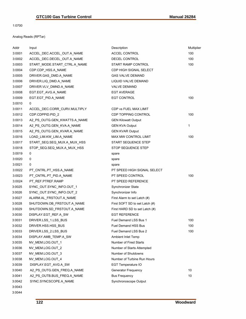
GTC100 Gas Turbine Control Manual 26284
122 Woodward
1:0700
Analog Reads (RPTar)
Addr Input Description Multiplier
3:0001 ACCEL_DEC.ACCEL_OUT.A_NAME ACCEL CONTROL 100
3:0002 ACCEL_DEC.DECEL_OUT.A_NAME DECEL CONTROL 100
3:0003 START_MODE.START_CTRL.A_NAME START RAMP CONTROL 100
3:0004 CDP.CDP_HSS.A_NAME CDP HIGH SIGNAL SELECT
3:0005 DRIVER.GAS_DMD.A_NAME GAS VALVE DEMAND
3:0006 DRIVER.LIQ_DMD.A_NAME LIQUID VALVE DEMAND
3:0007 DRIVER.VLV_DMND.A_NAME VALVE DEMAND
3:0008 EGT.EGT_AVG.A_NAME EGT AVERAGE
3:0009 EGT.EGT_PID.A_NAME EGT CONTROL 100
3:0010 0
3:0011 ACCEL_DEC.CORR_CURV.MULTIPLY CDP vs FUEL MAX LIMIT
3:0012 CDP.CDPPID.PID_2 CDP TOPPING CONTROL 100
3:0013 A2_PS_OUTG.GEN_KWATTS.A_NAME GEN Kilowatt Output
3:0014 A2_PS_OUTG.GEN_KVA.A_NAME GEN KVA Output 1
3:0015 A2_PS_OUTG.GEN_KVAR.A_NAME GEN KVAR Output
3:0016 LOAD_LIM.KW_LIM.A_NAME MAX MW CONTROL LIMIT 100
3:0017 START_SEQ.SEQ_MUX.A_MUX_HSS START SEQUENCE STEP
3:0018 STOP_SEQ.SEQ_MUX.A_MUX_HSS STOP SEQUENCE STEP
3:0019 0 spare
3:0020 0 spare
3:0021 0 spare
3:0022 PT_CNTRL.PT_HSS.A_NAME PT SPEED HIGH SIGNAL SELECT
3:0023 PT_CNTRL.PT_PID.A_NAME PT SPEED CONTROL 100
3:0024 PT_REF.PTREF.RAMP PT SPEED REFERENCE
3:0025 SYNC_OUT.SYNC_INFO.OUT_1 Synchronizer State
3:0026 SYNC_OUT.SYNC_INFO.OUT_2 Synchronizer Info
3:0027 ALARM.AL_FRSTOUT.A_NAME First Alarm to set Latch (#)
3:0028 SHUTDOWN.OB_FRSTOUT.A_NAME First SOFT SD to set Latch (#)
3:0029 SHUTDOWN.SD_FRSTOUT.A_NAME First HARD SD to set Latch (#)
3:0030 DISPLAY.EGT_REF.A_SW EGT REFERENCE
3:0031 DRIVER.LSS_1.LSS_BUS Fuel Demand LSS Bus 1 100
3:0032 DRIVER.HSS.HSS_BUS Fuel Demand HSS Bus 100
3:0033 DRIVER.LSS_2.LSS_BUS Fuel Demand LSS Bus 2 100
3:0034 DISPLAY.AMB_TEMP.A_SW Ambient Inlet Temp
3:0035 NV_MEM.LOG.OUT_1 Number of Fired Starts
3:0036 NV_MEM.LOG.OUT_2 Number of Starts Attempted
3:0037 NV_MEM.LOG.OUT_3 Number of Shutdowns
3:0038 NV_MEM.LOG.OUT_4 Number of Turbine Run Hours
3:0039 DISPLAY.EGT_AVG.A_SW EGT Temperature IO
3:0040 A2_PS_OUTG.GEN_FREQ.A_NAME Generator Frequency 10
3:0041 A2_PS_OUTB.BUS_FREQ.A_NAME Bus Frequency 10
3:0042 SYNC.SYNCSCOPE.A_NAME Synchronoscope Output
3:0043
3:0044
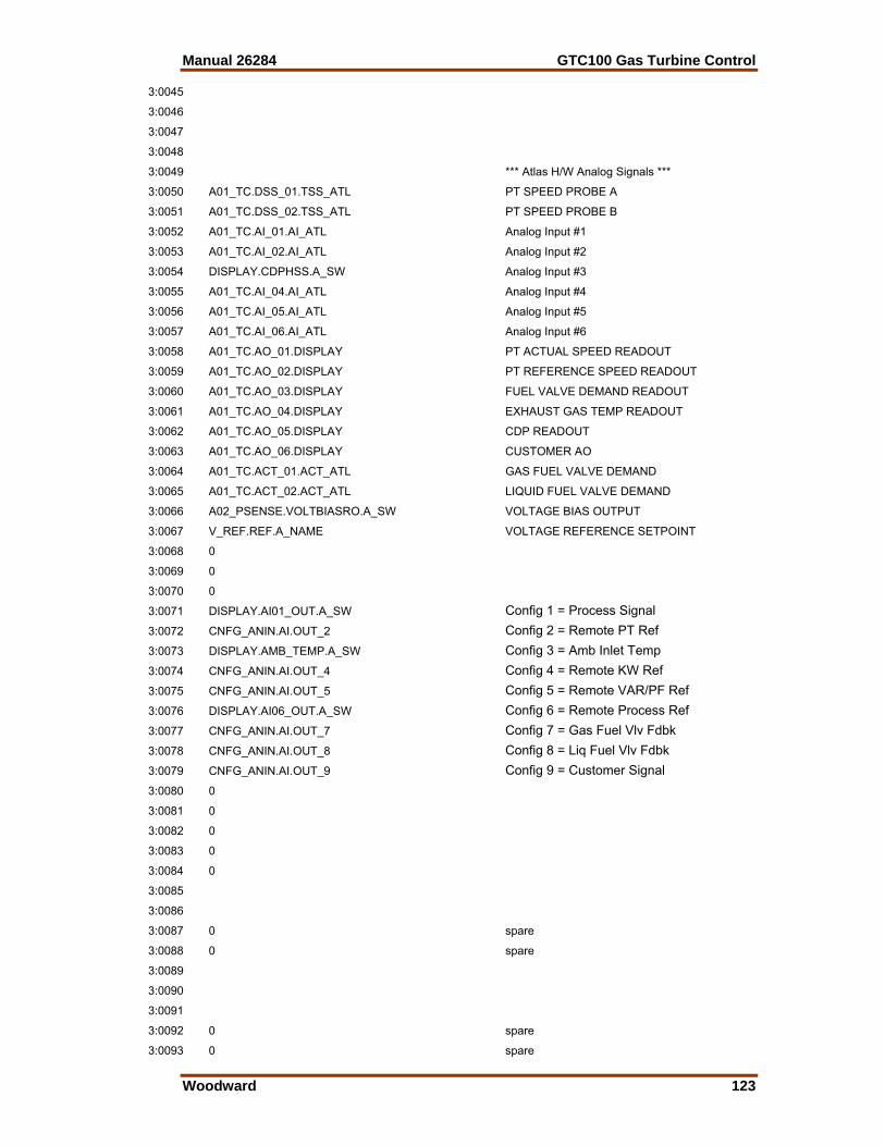
Manual 26284 GTC100 Gas Turbine Control
Woodward 123
3:0045
3:0046
3:0047
3:0048
3:0049 *** Atlas H/W Analog Signals ***
3:0050 A01_TC.DSS_01.TSS_ATL PT SPEED PROBE A
3:0051 A01_TC.DSS_02.TSS_ATL PT SPEED PROBE B
3:0052 A01_TC.AI_01.AI_ATL Analog Input #1
3:0053 A01_TC.AI_02.AI_ATL Analog Input #2
3:0054 DISPLAY.CDPHSS.A_SW Analog Input #3
3:0055 A01_TC.AI_04.AI_ATL Analog Input #4
3:0056 A01_TC.AI_05.AI_ATL Analog Input #5
3:0057 A01_TC.AI_06.AI_ATL Analog Input #6
3:0058 A01_TC.AO_01.DISPLAY PT ACTUAL SPEED READOUT
3:0059 A01_TC.AO_02.DISPLAY PT REFERENCE SPEED READOUT
3:0060 A01_TC.AO_03.DISPLAY FUEL VALVE DEMAND READOUT
3:0061 A01_TC.AO_04.DISPLAY EXHAUST GAS TEMP READOUT
3:0062 A01_TC.AO_05.DISPLAY CDP READOUT
3:0063 A01_TC.AO_06.DISPLAY CUSTOMER AO
3:0064 A01_TC.ACT_01.ACT_ATL GAS FUEL VALVE DEMAND
3:0065 A01_TC.ACT_02.ACT_ATL LIQUID FUEL VALVE DEMAND
3:0066 A02_PSENSE.VOLTBIASRO.A_SW VOLTAGE BIAS OUTPUT
3:0067 V_REF.REF.A_NAME VOLTAGE REFERENCE SETPOINT
3:0068 0
3:0069 0
3:0070 0
3:0071 DISPLAY.AI01_OUT.A_SW Config 1 = Process Signal
3:0072 CNFG_ANIN.AI.OUT_2 Config 2 = Remote PT Ref
3:0073 DISPLAY.AMB_TEMP.A_SW Config 3 = Amb Inlet Temp
3:0074 CNFG_ANIN.AI.OUT_4 Config 4 = Remote KW Ref
3:0075 CNFG_ANIN.AI.OUT_5 Config 5 = Remote VAR/PF Ref
3:0076 DISPLAY.AI06_OUT.A_SW Config 6 = Remote Process Ref
3:0077 CNFG_ANIN.AI.OUT_7 Config 7 = Gas Fuel Vlv Fdbk
3:0078 CNFG_ANIN.AI.OUT_8 Config 8 = Liq Fuel Vlv Fdbk
3:0079 CNFG_ANIN.AI.OUT_9 Config 9 = Customer Signal
3:0080 0
3:0081 0
3:0082 0
3:0083 0
3:0084 0
3:0085
3:0086
3:0087 0 spare
3:0088 0 spare
3:0089
3:0090
3:0091
3:0092 0 spare
3:0093 0 spare
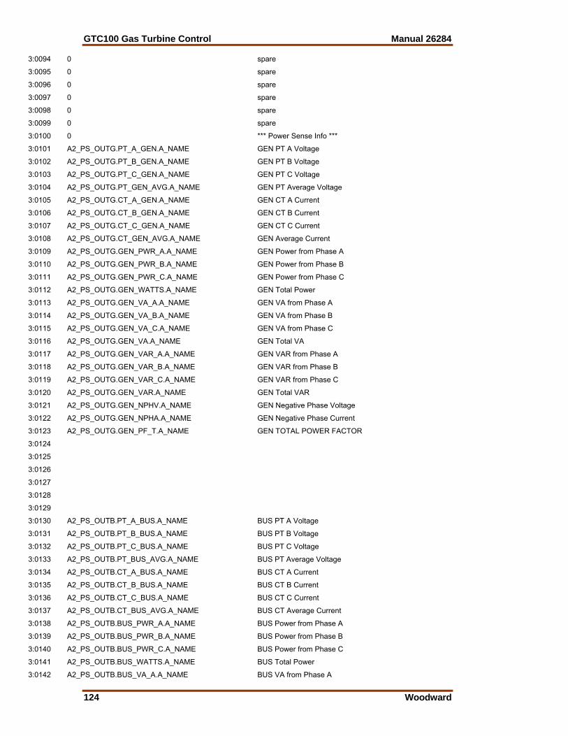
GTC100 Gas Turbine Control Manual 26284
124 Woodward
3:0094 0 spare
3:0095 0 spare
3:0096 0 spare
3:0097 0 spare
3:0098 0 spare
3:0099 0 spare
3:0100 0 *** Power Sense Info ***
3:0101 A2_PS_OUTG.PT_A_GEN.A_NAME GEN PT A Voltage
3:0102 A2_PS_OUTG.PT_B_GEN.A_NAME GEN PT B Voltage
3:0103 A2_PS_OUTG.PT_C_GEN.A_NAME GEN PT C Voltage
3:0104 A2_PS_OUTG.PT_GEN_AVG.A_NAME GEN PT Average Voltage
3:0105 A2_PS_OUTG.CT_A_GEN.A_NAME GEN CT A Current
3:0106 A2_PS_OUTG.CT_B_GEN.A_NAME GEN CT B Current
3:0107 A2_PS_OUTG.CT_C_GEN.A_NAME GEN CT C Current
3:0108 A2_PS_OUTG.CT_GEN_AVG.A_NAME GEN Average Current
3:0109 A2_PS_OUTG.GEN_PWR_A.A_NAME GEN Power from Phase A
3:0110 A2_PS_OUTG.GEN_PWR_B.A_NAME GEN Power from Phase B
3:0111 A2_PS_OUTG.GEN_PWR_C.A_NAME GEN Power from Phase C
3:0112 A2_PS_OUTG.GEN_WATTS.A_NAME GEN Total Power
3:0113 A2_PS_OUTG.GEN_VA_A.A_NAME GEN VA from Phase A
3:0114 A2_PS_OUTG.GEN_VA_B.A_NAME GEN VA from Phase B
3:0115 A2_PS_OUTG.GEN_VA_C.A_NAME GEN VA from Phase C
3:0116 A2_PS_OUTG.GEN_VA.A_NAME GEN Total VA
3:0117 A2_PS_OUTG.GEN_VAR_A.A_NAME GEN VAR from Phase A
3:0118 A2_PS_OUTG.GEN_VAR_B.A_NAME GEN VAR from Phase B
3:0119 A2_PS_OUTG.GEN_VAR_C.A_NAME GEN VAR from Phase C
3:0120 A2_PS_OUTG.GEN_VAR.A_NAME GEN Total VAR
3:0121 A2_PS_OUTG.GEN_NPHV.A_NAME GEN Negative Phase Voltage
3:0122 A2_PS_OUTG.GEN_NPHA.A_NAME GEN Negative Phase Current
3:0123 A2_PS_OUTG.GEN_PF_T.A_NAME GEN TOTAL POWER FACTOR
3:0124
3:0125
3:0126
3:0127
3:0128
3:0129
3:0130 A2_PS_OUTB.PT_A_BUS.A_NAME BUS PT A Voltage
3:0131 A2_PS_OUTB.PT_B_BUS.A_NAME BUS PT B Voltage
3:0132 A2_PS_OUTB.PT_C_BUS.A_NAME BUS PT C Voltage
3:0133 A2_PS_OUTB.PT_BUS_AVG.A_NAME BUS PT Average Voltage
3:0134 A2_PS_OUTB.CT_A_BUS.A_NAME BUS CT A Current
3:0135 A2_PS_OUTB.CT_B_BUS.A_NAME BUS CT B Current
3:0136 A2_PS_OUTB.CT_C_BUS.A_NAME BUS CT C Current
3:0137 A2_PS_OUTB.CT_BUS_AVG.A_NAME BUS CT Average Current
3:0138 A2_PS_OUTB.BUS_PWR_A.A_NAME BUS Power from Phase A
3:0139 A2_PS_OUTB.BUS_PWR_B.A_NAME BUS Power from Phase B
3:0140 A2_PS_OUTB.BUS_PWR_C.A_NAME BUS Power from Phase C
3:0141 A2_PS_OUTB.BUS_WATTS.A_NAME BUS Total Power
3:0142 A2_PS_OUTB.BUS_VA_A.A_NAME BUS VA from Phase A
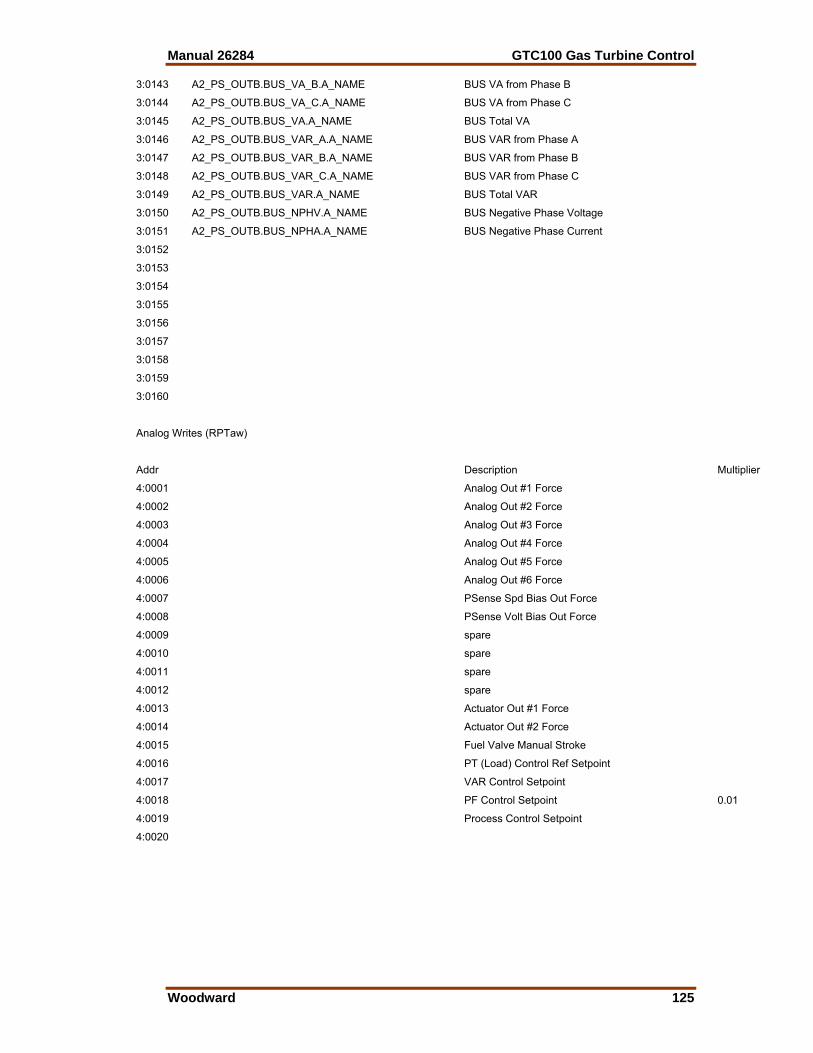
Manual 26284 GTC100 Gas Turbine Control
Woodward 125
3:0143 A2_PS_OUTB.BUS_VA_B.A_NAME BUS VA from Phase B
3:0144 A2_PS_OUTB.BUS_VA_C.A_NAME BUS VA from Phase C
3:0145 A2_PS_OUTB.BUS_VA.A_NAME BUS Total VA
3:0146 A2_PS_OUTB.BUS_VAR_A.A_NAME BUS VAR from Phase A
3:0147 A2_PS_OUTB.BUS_VAR_B.A_NAME BUS VAR from Phase B
3:0148 A2_PS_OUTB.BUS_VAR_C.A_NAME BUS VAR from Phase C
3:0149 A2_PS_OUTB.BUS_VAR.A_NAME BUS Total VAR
3:0150 A2_PS_OUTB.BUS_NPHV.A_NAME BUS Negative Phase Voltage
3:0151 A2_PS_OUTB.BUS_NPHA.A_NAME BUS Negative Phase Current
3:0152
3:0153
3:0154
3:0155
3:0156
3:0157
3:0158
3:0159
3:0160
Analog Writes (RPTaw)
Addr Description Multiplier
4:0001 Analog Out #1 Force
4:0002 Analog Out #2 Force
4:0003 Analog Out #3 Force
4:0004 Analog Out #4 Force
4:0005 Analog Out #5 Force
4:0006 Analog Out #6 Force
4:0007 PSense Spd Bias Out Force
4:0008 PSense Volt Bias Out Force
4:0009 spare
4:0010 spare
4:0011 spare
4:0012 spare
4:0013 Actuator Out #1 Force
4:0014 Actuator Out #2 Force
4:0015 Fuel Valve Manual Stroke
4:0016 PT (Load) Control Ref Setpoint
4:0017 VAR Control Setpoint
4:0018 PF Control Setpoint 0.01
4:0019 Process Control Setpoint
4:0020

GTC100 Gas Turbine Control Manual 26284
126 Woodward
Appendix C. Alarm/Shutdown Event List
When an event occurs, the application sets a numbered Alarm flag (latch) as per the list below. The action to be taken is determined by the configuration option that the user selects for each event. The Quick Service inspector file has a user tunable value for the configuration number as per the chart below. The programmed default actions for these events are shown in the list below. The ACKNOWLEDGE input will turn off the Horn output. The RESET will clear the event latch, if the event condition no longer exists. Event options are as follows: Configuration Number
Description
1 Disabled (No action taken) 2 Alarm (Audible & Visual annunciation of event) 3 Soft Shutdown (same as Alarm w/ Open Gen Breaker Command 4 Hard Shutdown (same as Soft w/ Fuel Shut-off) 5 Reserved (Not currently used)
Some events are programmed as Hard Shutdowns and are not tunable, such as All Speed Sensors Failed, PT Overspeed, EGT Overtemp, and the Fuel Driver Faults.
Event # DESCRIPTION DEFAULT Site Option
AL_001 Atlas HW/OpSys Summary Fault HARD SHUTDOWN
AL 002 Atlas Input Power Alarm ALARM
AL 003 Atlas HW Hi Temp ALARM
AL 004 Control is NOT Configured HARD SHUTDOWN
AL_005 Serial Port #1 Fault ALARM
AL_006 Serial Port #2 Fault Disabled
AL 007 Distributed IO Fault Disabled
AL 008 Speed Signal #1 Failed ALARM
AL 009 Speed Signal #2 Failed ALARM
AL_010 Analog Input # 1 Failed ALARM
AL_011 Analog Input # 2 Failed ALARM
AL 012 Analog Input # 3 Failed ALARM
AL 013 Analog Input # 4 Failed ALARM
AL 014 Analog Input # 5 Failed ALARM
AL_015 Analog Input # 6 Failed HARD SHUTDOWN
AL_016 Discrete Input # 01 triggered event HARD SHUTDOWN
AL 017 Not Used Disabled
AL 018 Not Used Disabled
AL 019 Discrete Input # 04 triggered event Disabled
AL_020 Discrete Input # 05 triggered event Disabled
AL 021 Discrete Input # 06 triggered event Disabled
AL 022 Discrete Input # 07 triggered event Disabled
AL 023 Discrete Input # 08 triggered event Disabled
AL 024 Discrete Input # 09 triggered event Disabled
AL_025 Discrete Input # 10 triggered event Disabled
AL_026 Discrete Input # 11 triggered event Disabled
AL 027 Discrete Input # 12 triggered event Disabled
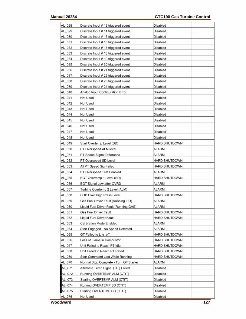
Manual 26284 GTC100 Gas Turbine Control
Woodward 127
AL_028 Discrete Input # 13 triggered event Disabled
AL_029 Discrete Input # 14 triggered event Disabled
AL 030 Discrete Input # 15 triggered event Disabled
AL 031 Discrete Input # 16 triggered event Disabled
AL 032 Discrete Input # 17 triggered event Disabled
AL_033 Discrete Input # 18 triggered event Disabled
AL_034 Discrete Input # 19 triggered event Disabled
AL 035 Discrete Input # 20 triggered event Disabled
AL 036 Discrete Input # 21 triggered event Disabled
AL 037 Discrete Input # 22 triggered event Disabled
AL_038 Discrete Input # 23 triggered event Disabled
AL_039 Discrete Input # 24 triggered event Disabled
AL 040 Analog Input Configuration Error Disabled
AL 041 Not Used Disabled
AL 042 Not Used Disabled
AL_043 Not Used Disabled
AL_044 Not Used Disabled
AL 045 Not Used Disabled
AL 046 Not Used Disabled
AL 047 Not Used Disabled
AL_048 Not Used Disabled
AL 049 Start Overtemp Level (SD) HARD SHUTDOWN
AL 050 PT Overspeed ALM level ALARM
AL_051 PT Speed Signal Difference ALARM
AL 052 PT Overspeed SD Level HARD SHUTDOWN
AL 053 All PT Speed Sig Failed HARD SHUTDOWN
AL_054 PT Overspeed Test Enabled ALARM
AL_055 EGT Overtemp 1 Level (SD) HARD SHUTDOWN
AL 056 EGT Signal Low after OVRD ALARM
AL 057 Turbine Overtemp 2 Level (ALM) ALARM
AL_058 CDP Over High Press Level HARD SHUTDOWN
AL 059 Gas Fuel Driver Fault (Running LIQ) ALARM
AL 060 Liquid Fuel Driver Fault (Running GAS) ALARM
AL 061 Gas Fuel Driver Fault HARD SHUTDOWN
AL 062 Liquid Fuel Driver Fault HARD SHUTDOWN
AL_063 Cal bration Mode Enabled ALARM
AL_064 Start Engaged - No Speed Detected ALARM
AL 065 GT Failed to Lite off HARD SHUTDOWN
AL 066 Loss of Flame in Combustor HARD SHUTDOWN
AL 067 Unit Failed to Reach PT Idle HARD SHUTDOWN
AL_068 Unit Failed to Reach PT Rated HARD SHUTDOWN
AL_069 Start Command Lost While Running HARD SHUTDOWN
AL 070 Normal Stop Complete - Turn Off Starter ALARM
AL_071 Alternate Temp Signal (TIT) Failed Disabled
AL 072 Running OVERTEMP ALM (CTIT) Disabled
AL 073 Starting OVERTEMP ALM (CTIT) Disabled
AL 074 Runnng OVERTEMP SD (CTIT) Disabled
AL_075 Starting OVERTEMP SD (CTIT) Disabled
AL_076 Not Used Disabled
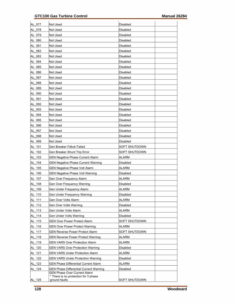
GTC100 Gas Turbine Control Manual 26284
128 Woodward
AL_077 Not Used Disabled
AL_078 Not Used Disabled
AL 079 Not Used Disabled
AL 080 Not Used Disabled
AL 081 Not Used Disabled
AL_082 Not Used Disabled
AL_083 Not Used Disabled
AL 084 Not Used Disabled
AL 085 Not Used Disabled
AL 086 Not Used Disabled
AL_087 Not Used Disabled
AL_088 Not Used Disabled
AL 089 Not Used Disabled
AL 090 Not Used Disabled
AL 091 Not Used Disabled
AL_092 Not Used Disabled
AL_093 Not Used Disabled
AL 094 Not Used Disabled
AL 095 Not Used Disabled
AL 096 Not Used Disabled
AL_097 Not Used Disabled
AL_098 Not Used Disabled
AL 099 Not Used Disabled
AL 101 Gen Breaker Fdbck Failed SOFT SHUTDOWN
AL 102 Gen Breaker Shunt Trip Error SOFT SHUTDOWN
AL_103 GEN Negative Phase Current Alarm ALARM
AL_104 GEN Negative Phase Current Warning Disabled
AL 105 GEN Negative Phase Volt Alarm ALARM
AL 106 GEN Negative Phase Volt Warning Disabled
AL 107 Gen Over Frequency Alarm ALARM
AL_108 Gen Over Frequency Warning Disabled
AL_109 Gen Under Frequency Alarm ALARM
AL 110 Gen Under Frequency Warning Disabled
AL 111 Gen Over Volts Alarm ALARM
AL 112 Gen Over Volts Warning Disabled
AL_113 Gen Under Volts Alarm ALARM
AL_114 Gen Under Volts Warning Disabled
AL 115 GEN Over Power Protect Alarm SOFT SHUTDOWN
AL 116 GEN Over Power Protect Warning ALARM
AL 117 GEN Reverse Power Protect Alarm SOFT SHUTDOWN
AL_118 GEN Reverse Power Protect Warning ALARM
AL_119 GEN VARS Over Protection Alarm ALARM
AL 120 GEN VARS Over Protection Warning Disabled
AL 121 GEN VARS Under Protection Alarm ALARM
AL 122 GEN VARS Under Protection Warning Disabled
AL_123 GEN Phase Differential Current Alarm ALARM
AL_124 GEN Phase Differential Current Warning Disabled
AL_125
GEN Phase Over Current Alarm * There is no protection for 3 phase ground faults SOFT SHUTDOWN
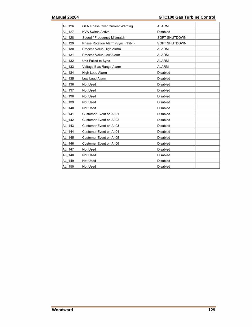
Manual 26284 GTC100 Gas Turbine Control
Woodward 129
AL_126 GEN Phase Over Current Warning ALARM
AL_127 KVA Switch Active Disabled
AL 128 Speed / Frequency Mismatch SOFT SHUTDOWN
AL 129 Phase Rotation Alarm (Sync Inhibit) SOFT SHUTDOWN
AL 130 Process Value High Alarm ALARM
AL 131 Process Value Low Alarm ALARM
AL 132 Unit Failed to Sync ALARM
AL_133 Voltage Bias Range Alarm ALARM
AL 134 High Load Alarm Disabled
AL 135 Low Load Alarm Disabled
AL_136 Not Used Disabled
AL 137 Not Used Disabled
AL 138 Not Used Disabled
AL_139 Not Used Disabled
AL 140 Not Used Disabled
AL 141 Customer Event on AI 01 Disabled
AL_142 Customer Event on AI 02 Disabled
AL 143 Customer Event on AI 03 Disabled
AL 144 Customer Event on AI 04 Disabled
AL 145 Customer Event on AI 05 Disabled
AL_146 Customer Event on AI 06 Disabled
AL 147 Not Used Disabled
AL_148 Not Used Disabled
AL_149 Not Used Disabled
AL 150 Not Used Disabled

GTC100 Gas Turbine Control Manual 26284
130 Woodward
Appendix D. Configuration and Service Tunables
Worksheet Control Part Number ____________________ Software Number & Revision Letter ____________________ Control Serial Number ____________________ I/O CONFIGURATION NOTES MPUs: PT MPUs: Maximum frequency sensing = 25000 Hz Single or Redundant Sensors TEMPERATURE INPUT (summary input): EGT: input in Deg. F, 4-20mA – Required on Analog Input Channel # 6 COMPRESSOR DISCHARGE PRESSURE INPUT: CDP: input in psia, 4-20mA – If used must be on Analog Input Channel # 3 SERVICE & CONFIGURATION HEADER NOTES: Below is a list of the Quickservice Inspector File that is used to configure the control. Each Tab sheet is listed below with a column available for the user to record the correct value for their unit. The column identify by the T * indicates that rows value as tunable. CONFIGURE SHEETS The following section outlines optional configurations that can be adjusted in this standard control. These should be checked at the site to be sure they are correct for the turbine being controlled. The default value and range are shown for each tunable. The turbine must be shutdown to adjust the tunables in Configure mode, as it will place the control in IO LOCK. ************************************************** ** LIST OF CONFIGURE SHEET TAB HEADERS ** ************************************************** ** CONFIGURE: C1- A - SYSTEM ** ** CONFIGURE: C2- B - Psense SETTINGS** ** CONFIGURE: C3- C - SPEED SENSOR SETTINGS** ** CONFIGURE: C4- D - ANALOG IN OPTS (4=MAX)** ** CONFIGURE: C5- E - EGT SETTINGS**
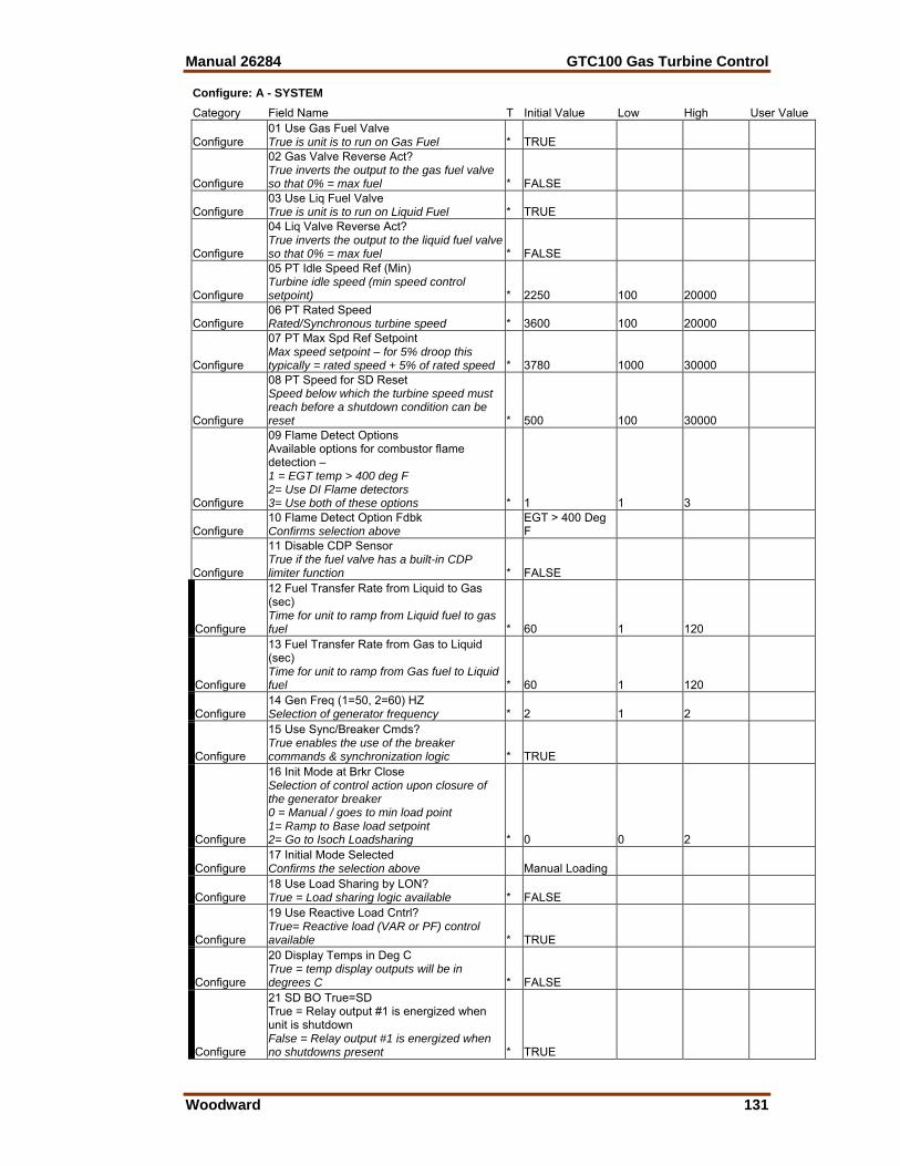
Manual 26284 GTC100 Gas Turbine Control
Woodward 131
Configure: A - SYSTEM Category Field Name T Initial Value Low High User Value
Configure 01 Use Gas Fuel Valve True is unit is to run on Gas Fuel * TRUE
Configure
02 Gas Valve Reverse Act? True inverts the output to the gas fuel valve so that 0% = max fuel * FALSE
Configure 03 Use Liq Fuel Valve True is unit is to run on Liquid Fuel * TRUE
Configure
04 Liq Valve Reverse Act? True inverts the output to the liquid fuel valve so that 0% = max fuel * FALSE
Configure
05 PT Idle Speed Ref (Min) Turbine idle speed (min speed control setpoint) * 2250 100 20000
Configure 06 PT Rated Speed Rated/Synchronous turbine speed * 3600 100 20000
Configure
07 PT Max Spd Ref Setpoint Max speed setpoint – for 5% droop this typically = rated speed + 5% of rated speed * 3780 1000 30000
Configure
08 PT Speed for SD Reset Speed below which the turbine speed must reach before a shutdown condition can be reset * 500 100 30000
Configure
09 Flame Detect Options Available options for combustor flame detection – 1 = EGT temp > 400 deg F 2= Use DI Flame detectors 3= Use both of these options * 1 1 3
Configure 10 Flame Detect Option Fdbk Confirms selection above
EGT > 400 Deg F
Configure
11 Disable CDP Sensor True if the fuel valve has a built-in CDP limiter function * FALSE
Configure
12 Fuel Transfer Rate from Liquid to Gas (sec) Time for unit to ramp from Liquid fuel to gas fuel * 60 1 120
Configure
13 Fuel Transfer Rate from Gas to Liquid (sec) Time for unit to ramp from Gas fuel to Liquid fuel * 60 1 120
Configure 14 Gen Freq (1=50, 2=60) HZ Selection of generator frequency * 2 1 2
Configure
15 Use Sync/Breaker Cmds? True enables the use of the breaker commands & synchronization logic * TRUE
Configure
16 Init Mode at Brkr Close Selection of control action upon closure of the generator breaker 0 = Manual / goes to min load point 1= Ramp to Base load setpoint 2= Go to Isoch Loadsharing * 0 0 2
Configure 17 Initial Mode Selected Confirms the selection above Manual Loading
Configure 18 Use Load Sharing by LON? True = Load sharing logic available * FALSE
Configure
19 Use Reactive Load Cntrl? True= Reactive load (VAR or PF) control available * TRUE
Configure
20 Display Temps in Deg C True = temp display outputs will be in degrees C * FALSE
Configure
21 SD BO True=SD True = Relay output #1 is energized when unit is shutdown False = Relay output #1 is energized when no shutdowns present * TRUE
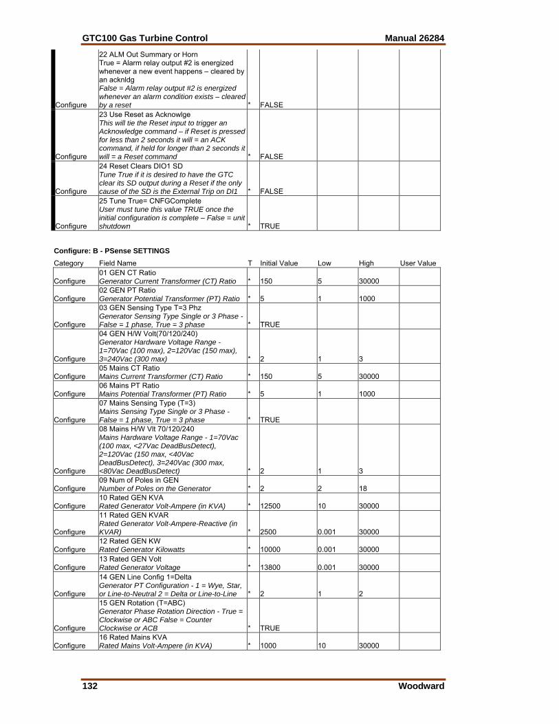
GTC100 Gas Turbine Control Manual 26284
132 Woodward
Configure
22 ALM Out Summary or Horn True = Alarm relay output #2 is energized whenever a new event happens – cleared by an acknldg False = Alarm relay output #2 is energized whenever an alarm condition exists – cleared by a reset * FALSE
Configure
23 Use Reset as Acknowlge This will tie the Reset input to trigger an Acknowledge command – if Reset is pressed for less than 2 seconds it will = an ACK command, if held for longer than 2 seconds it will = a Reset command * FALSE
Configure
24 Reset Clears DIO1 SD Tune True if it is desired to have the GTC clear its SD output during a Reset if the only cause of the SD is the External Trip on DI1 * FALSE
Configure
25 Tune True= CNFGComplete User must tune this value TRUE once the initial configuration is complete – False = unit shutdown * TRUE
Configure: B - PSense SETTINGS Category Field Name T Initial Value Low High User Value
Configure 01 GEN CT Ratio Generator Current Transformer (CT) Ratio * 150 5 30000
Configure 02 GEN PT Ratio Generator Potential Transformer (PT) Ratio * 5 1 1000
Configure
03 GEN Sensing Type T=3 Phz Generator Sensing Type Single or 3 Phase - False = 1 phase, True = 3 phase * TRUE
Configure
04 GEN H/W Volt(70/120/240) Generator Hardware Voltage Range - 1=70Vac (100 max), 2=120Vac (150 max), 3=240Vac (300 max) * 2 1 3
Configure 05 Mains CT Ratio Mains Current Transformer (CT) Ratio * 150 5 30000
Configure 06 Mains PT Ratio Mains Potential Transformer (PT) Ratio * 5 1 1000
Configure
07 Mains Sensing Type (T=3) Mains Sensing Type Single or 3 Phase - False = 1 phase, True = 3 phase * TRUE
Configure
08 Mains H/W Vlt 70/120/240 Mains Hardware Voltage Range - 1=70Vac (100 max, <27Vac DeadBusDetect), 2=120Vac (150 max, <40Vac DeadBusDetect), 3=240Vac (300 max, <80Vac DeadBusDetect) * 2 1 3
Configure 09 Num of Poles in GEN Number of Poles on the Generator * 2 2 18
Configure 10 Rated GEN KVA Rated Generator Volt-Ampere (in KVA) * 12500 10 30000
Configure
11 Rated GEN KVAR Rated Generator Volt-Ampere-Reactive (in KVAR) * 2500 0.001 30000
Configure 12 Rated GEN KW Rated Generator Kilowatts * 10000 0.001 30000
Configure 13 Rated GEN Volt Rated Generator Voltage * 13800 0.001 30000
Configure
14 GEN Line Config 1=Delta Generator PT Configuration - 1 = Wye, Star, or Line-to-Neutral 2 = Delta or Line-to-Line * 2 1 2
Configure
15 GEN Rotation (T=ABC) Generator Phase Rotation Direction - True = Clockwise or ABC False = Counter Clockwise or ACB * TRUE
Configure 16 Rated Mains KVA Rated Mains Volt-Ampere (in KVA) * 1000 10 30000
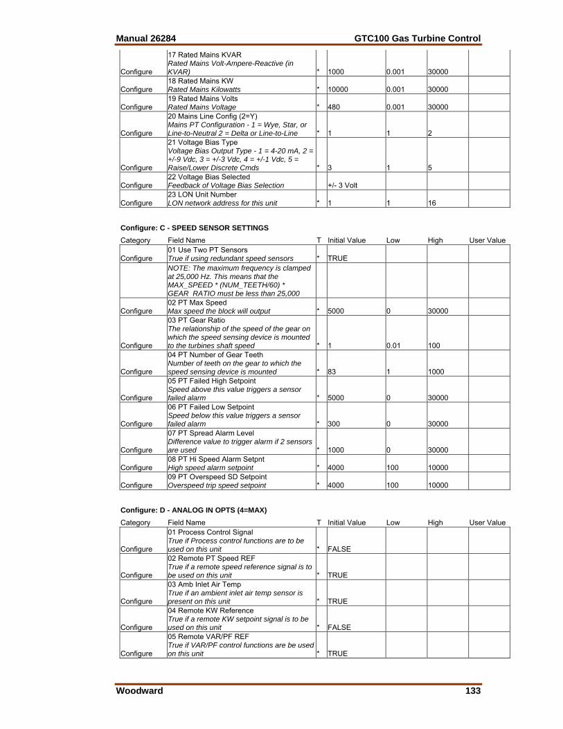
Manual 26284 GTC100 Gas Turbine Control
Woodward 133
Configure
17 Rated Mains KVAR Rated Mains Volt-Ampere-Reactive (in KVAR) * 1000 0.001 30000
Configure 18 Rated Mains KW Rated Mains Kilowatts * 10000 0.001 30000
Configure 19 Rated Mains Volts Rated Mains Voltage * 480 0.001 30000
Configure
20 Mains Line Config (2=Y) Mains PT Configuration - 1 = Wye, Star, or Line-to-Neutral 2 = Delta or Line-to-Line * 1 1 2
Configure
21 Voltage Bias Type Voltage Bias Output Type - 1 = 4-20 mA, 2 = +/-9 Vdc, 3 = +/-3 Vdc, 4 = +/-1 Vdc, 5 = Raise/Lower Discrete Cmds * 3 1 5
Configure 22 Voltage Bias Selected Feedback of Voltage Bias Selection +/- 3 Volt
Configure 23 LON Unit Number LON network address for this unit * 1 1 16
Configure: C - SPEED SENSOR SETTINGS Category Field Name T Initial Value Low High User Value
Configure 01 Use Two PT Sensors True if using redundant speed sensors * TRUE
NOTE: The maximum frequency is clamped at 25,000 Hz. This means that the MAX_SPEED * (NUM_TEETH/60) * GEAR RATIO must be less than 25,000
Configure 02 PT Max Speed Max speed the block will output * 5000 0 30000
Configure
03 PT Gear Ratio The relationship of the speed of the gear on which the speed sensing device is mounted to the turbines shaft speed * 1 0.01 100
Configure
04 PT Number of Gear Teeth Number of teeth on the gear to which the speed sensing device is mounted * 83 1 1000
Configure
05 PT Failed High Setpoint Speed above this value triggers a sensor failed alarm * 5000 0 30000
Configure
06 PT Failed Low Setpoint Speed below this value triggers a sensor failed alarm * 300 0 30000
Configure
07 PT Spread Alarm Level Difference value to trigger alarm if 2 sensors are used * 1000 0 30000
Configure 08 PT Hi Speed Alarm Setpnt High speed alarm setpoint * 4000 100 10000
Configure 09 PT Overspeed SD Setpoint Overspeed trip speed setpoint * 4000 100 10000
Configure: D - ANALOG IN OPTS (4=MAX) Category Field Name T Initial Value Low High User Value
Configure
01 Process Control Signal True if Process control functions are to be used on this unit * FALSE
Configure
02 Remote PT Speed REF True if a remote speed reference signal is to be used on this unit * TRUE
Configure
03 Amb Inlet Air Temp True if an ambient inlet air temp sensor is present on this unit * TRUE
Configure
04 Remote KW Reference True if a remote KW setpoint signal is to be used on this unit * FALSE
Configure
05 Remote VAR/PF REF True if VAR/PF control functions are be used on this unit * TRUE
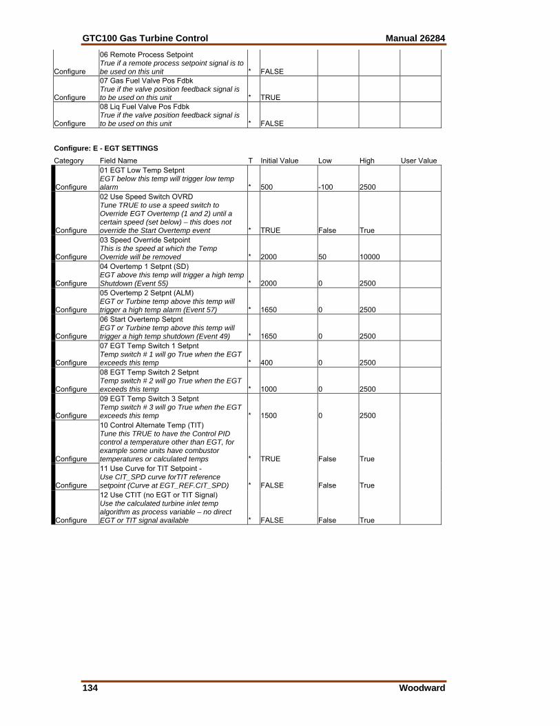
GTC100 Gas Turbine Control Manual 26284
134 Woodward
Configure
06 Remote Process Setpoint True if a remote process setpoint signal is to be used on this unit * FALSE
Configure
07 Gas Fuel Valve Pos Fdbk True if the valve position feedback signal is to be used on this unit * TRUE
Configure
08 Liq Fuel Valve Pos Fdbk True if the valve position feedback signal is to be used on this unit * FALSE
Configure: E - EGT SETTINGS Category Field Name T Initial Value Low High User Value
Configure
01 EGT Low Temp Setpnt EGT below this temp will trigger low temp alarm * 500 -100 2500
Configure
02 Use Speed Switch OVRD Tune TRUE to use a speed switch to Override EGT Overtemp (1 and 2) until a certain speed (set below) – this does not override the Start Overtemp event * TRUE False True
Configure
03 Speed Override Setpoint This is the speed at which the Temp Override will be removed * 2000 50 10000
Configure
04 Overtemp 1 Setpnt (SD) EGT above this temp will trigger a high temp Shutdown (Event 55) * 2000 0 2500
Configure
05 Overtemp 2 Setpnt (ALM) EGT or Turbine temp above this temp will trigger a high temp alarm (Event 57) * 1650 0 2500
Configure
06 Start Overtemp Setpnt EGT or Turbine temp above this temp will trigger a high temp shutdown (Event 49) * 1650 0 2500
Configure
07 EGT Temp Switch 1 Setpnt Temp switch # 1 will go True when the EGT exceeds this temp * 400 0 2500
Configure
08 EGT Temp Switch 2 Setpnt Temp switch # 2 will go True when the EGT exceeds this temp * 1000 0 2500
Configure
09 EGT Temp Switch 3 Setpnt Temp switch # 3 will go True when the EGT exceeds this temp * 1500 0 2500
Configure
10 Control Alternate Temp (TIT) Tune this TRUE to have the Control PID control a temperature other than EGT, for example some units have combustor temperatures or calculated temps * TRUE False True
Configure
11 Use Curve for TIT Setpoint - Use CIT_SPD curve forTIT reference setpoint (Curve at EGT_REF.CIT_SPD) * FALSE False True
Configure
12 Use CTIT (no EGT or TIT Signal) Use the calculated turbine inlet temp algorithm as process variable – no direct EGT or TIT signal available * FALSE False True
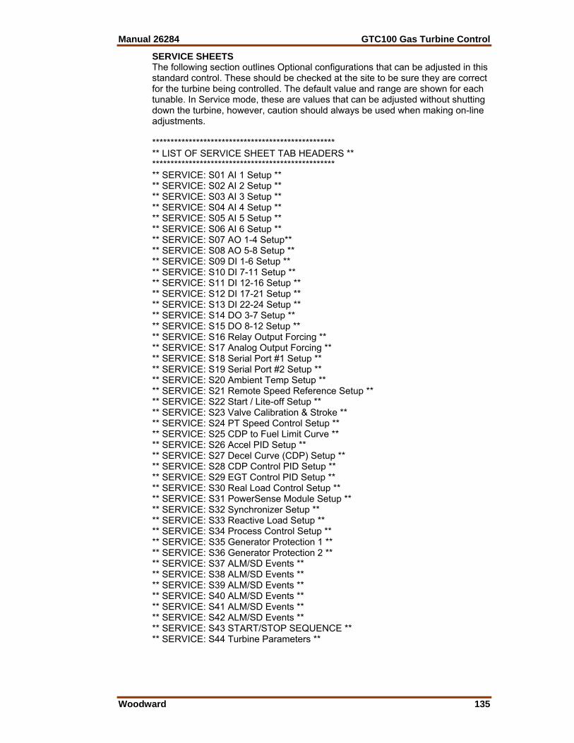
Manual 26284 GTC100 Gas Turbine Control
Woodward 135
SERVICE SHEETS The following section outlines Optional configurations that can be adjusted in this standard control. These should be checked at the site to be sure they are correct for the turbine being controlled. The default value and range are shown for each tunable. In Service mode, these are values that can be adjusted without shutting down the turbine, however, caution should always be used when making on-line adjustments. ************************************************** ** LIST OF SERVICE SHEET TAB HEADERS ** ************************************************** ** SERVICE: S01 AI 1 Setup ** ** SERVICE: S02 AI 2 Setup ** ** SERVICE: S03 AI 3 Setup ** ** SERVICE: S04 AI 4 Setup ** ** SERVICE: S05 AI 5 Setup ** ** SERVICE: S06 AI 6 Setup ** ** SERVICE: S07 AO 1-4 Setup** ** SERVICE: S08 AO 5-8 Setup ** ** SERVICE: S09 DI 1-6 Setup ** ** SERVICE: S10 DI 7-11 Setup ** ** SERVICE: S11 DI 12-16 Setup ** ** SERVICE: S12 DI 17-21 Setup ** ** SERVICE: S13 DI 22-24 Setup ** ** SERVICE: S14 DO 3-7 Setup ** ** SERVICE: S15 DO 8-12 Setup ** ** SERVICE: S16 Relay Output Forcing ** ** SERVICE: S17 Analog Output Forcing ** ** SERVICE: S18 Serial Port #1 Setup ** ** SERVICE: S19 Serial Port #2 Setup ** ** SERVICE: S20 Ambient Temp Setup ** ** SERVICE: S21 Remote Speed Reference Setup ** ** SERVICE: S22 Start / Lite-off Setup ** ** SERVICE: S23 Valve Calibration & Stroke ** ** SERVICE: S24 PT Speed Control Setup ** ** SERVICE: S25 CDP to Fuel Limit Curve ** ** SERVICE: S26 Accel PID Setup ** ** SERVICE: S27 Decel Curve (CDP) Setup ** ** SERVICE: S28 CDP Control PID Setup ** ** SERVICE: S29 EGT Control PID Setup ** ** SERVICE: S30 Real Load Control Setup ** ** SERVICE: S31 PowerSense Module Setup ** ** SERVICE: S32 Synchronizer Setup ** ** SERVICE: S33 Reactive Load Setup ** ** SERVICE: S34 Process Control Setup ** ** SERVICE: S35 Generator Protection 1 ** ** SERVICE: S36 Generator Protection 2 ** ** SERVICE: S37 ALM/SD Events ** ** SERVICE: S38 ALM/SD Events ** ** SERVICE: S39 ALM/SD Events ** ** SERVICE: S40 ALM/SD Events ** ** SERVICE: S41 ALM/SD Events ** ** SERVICE: S42 ALM/SD Events ** ** SERVICE: S43 START/STOP SEQUENCE ** ** SERVICE: S44 Turbine Parameters **
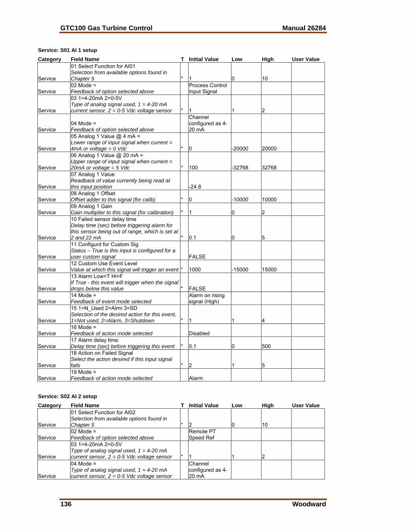
GTC100 Gas Turbine Control Manual 26284
136 Woodward
Service: S01 AI 1 setup Category Field Name T Initial Value Low High User Value
Service
01 Select Function for AI01 Selection from available options found in Chapter 5 * 1 0 10
Service 02 Mode = Feedback of option selected above
Process Control Input Signal
Service
03 1=4-20mA 2=0-5V Type of analog signal used, 1 = 4-20 mA current sensor, 2 = 0-5 Vdc voltage sensor * 1 1 2
Service 04 Mode = Feedback of option selected above
Channel configured as 4-20 mA
Service
05 Analog 1 Value @ 4 mA = Lower range of input signal when current = 4mA or voltage = 0 Vdc * 0 -20000 20000
Service
06 Analog 1 Value @ 20 mA = Upper range of input signal when current = 20mA or voltage = 5 Vdc * 100 -32768 32768
Service
07 Analog 1 Value Readback of value currently being read at this input position -24.8
Service 08 Analog 1 Offset Offset adder to this signal (for calib) * 0 -10000 10000
Service 09 Analog 1 Gain Gain multiplier to this signal (for calibration) * 1 0 2
Service
10 Failed sensor delay time Delay time (sec) before triggering alarm for this sensor being out of range, which is set at 2 and 22 mA * 0.1 0 5
Service
11 Configurd for Custom Sig Status – True is this input is configured for a user custom signal FALSE
Service 12 Custom Use Event Level Value at which this signal will trigger an event * 1000 -15000 15000
Service
13 Alarm Low=T Hi=F If True - this event will trigger when the signal drops below this value * FALSE
Service 14 Mode = Feedback of event mode selected
Alarm on rising signal (High)
Service
15 1=N_Used 2=Alrm 3=SD Selection of the desired action for this event, 1=Not used, 2=Alarm, 3=Shutdown * 1 1 4
Service 16 Mode = Feedback of action mode selected Disabled
Service 17 Alarm delay time Delay time (sec) before triggering this event * 0.1 0 500
Service
18 Action on Failed Signal Select the action desired if this input signal fails * 2 1 5
Service 19 Mode = Feedback of action mode selected Alarm
Service: S02 AI 2 setup Category Field Name T Initial Value Low High User Value
Service
01 Select Function for AI02 Selection from available options found in Chapter 5 * 2 0 10
Service 02 Mode = Feedback of option selected above
Remote PT Speed Ref
Service
03 1=4-20mA 2=0-5V Type of analog signal used, 1 = 4-20 mA current sensor, 2 = 0-5 Vdc voltage sensor * 1 1 2
Service
04 Mode = Type of analog signal used, 1 = 4-20 mA current sensor, 2 = 0-5 Vdc voltage sensor
Channel configured as 4-20 mA
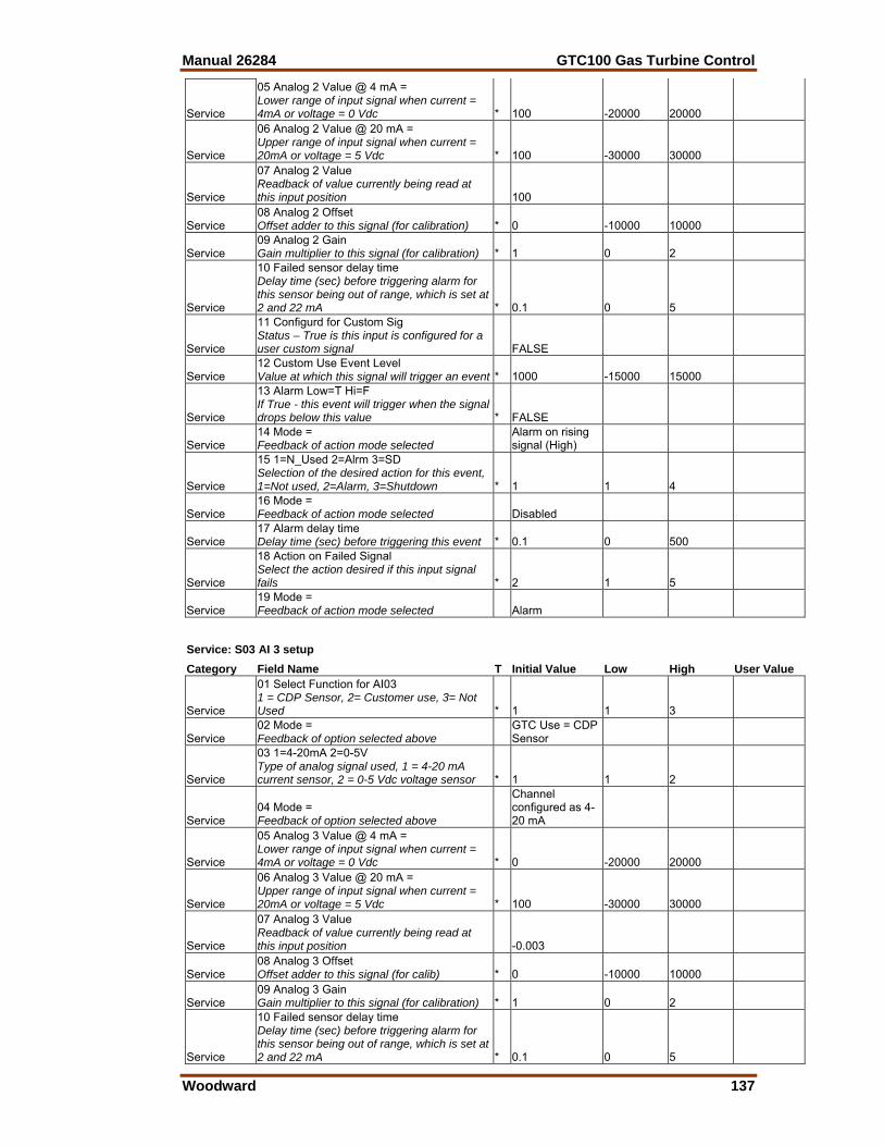
Manual 26284 GTC100 Gas Turbine Control
Woodward 137
Service
05 Analog 2 Value @ 4 mA = Lower range of input signal when current = 4mA or voltage = 0 Vdc * 100 -20000 20000
Service
06 Analog 2 Value @ 20 mA = Upper range of input signal when current = 20mA or voltage = 5 Vdc * 100 -30000 30000
Service
07 Analog 2 Value Readback of value currently being read at this input position 100
Service 08 Analog 2 Offset Offset adder to this signal (for calibration) * 0 -10000 10000
Service 09 Analog 2 Gain Gain multiplier to this signal (for calibration) * 1 0 2
Service
10 Failed sensor delay time Delay time (sec) before triggering alarm for this sensor being out of range, which is set at 2 and 22 mA * 0.1 0 5
Service
11 Configurd for Custom Sig Status – True is this input is configured for a user custom signal FALSE
Service 12 Custom Use Event Level Value at which this signal will trigger an event * 1000 -15000 15000
Service
13 Alarm Low=T Hi=F If True - this event will trigger when the signal drops below this value * FALSE
Service 14 Mode = Feedback of action mode selected
Alarm on rising signal (High)
Service
15 1=N_Used 2=Alrm 3=SD Selection of the desired action for this event, 1=Not used, 2=Alarm, 3=Shutdown * 1 1 4
Service 16 Mode = Feedback of action mode selected Disabled
Service 17 Alarm delay time Delay time (sec) before triggering this event * 0.1 0 500
Service
18 Action on Failed Signal Select the action desired if this input signal fails * 2 1 5
Service 19 Mode = Feedback of action mode selected Alarm
Service: S03 AI 3 setup Category Field Name T Initial Value Low High User Value
Service
01 Select Function for AI03 1 = CDP Sensor, 2= Customer use, 3= Not Used * 1 1 3
Service 02 Mode = Feedback of option selected above
GTC Use = CDP Sensor
Service
03 1=4-20mA 2=0-5V Type of analog signal used, 1 = 4-20 mA current sensor, 2 = 0-5 Vdc voltage sensor * 1 1 2
Service 04 Mode = Feedback of option selected above
Channel configured as 4-20 mA
Service
05 Analog 3 Value @ 4 mA = Lower range of input signal when current = 4mA or voltage = 0 Vdc * 0 -20000 20000
Service
06 Analog 3 Value @ 20 mA = Upper range of input signal when current = 20mA or voltage = 5 Vdc * 100 -30000 30000
Service
07 Analog 3 Value Readback of value currently being read at this input position -0.003
Service 08 Analog 3 Offset Offset adder to this signal (for calib) * 0 -10000 10000
Service 09 Analog 3 Gain Gain multiplier to this signal (for calibration) * 1 0 2
Service
10 Failed sensor delay time Delay time (sec) before triggering alarm for this sensor being out of range, which is set at 2 and 22 mA * 0.1 0 5
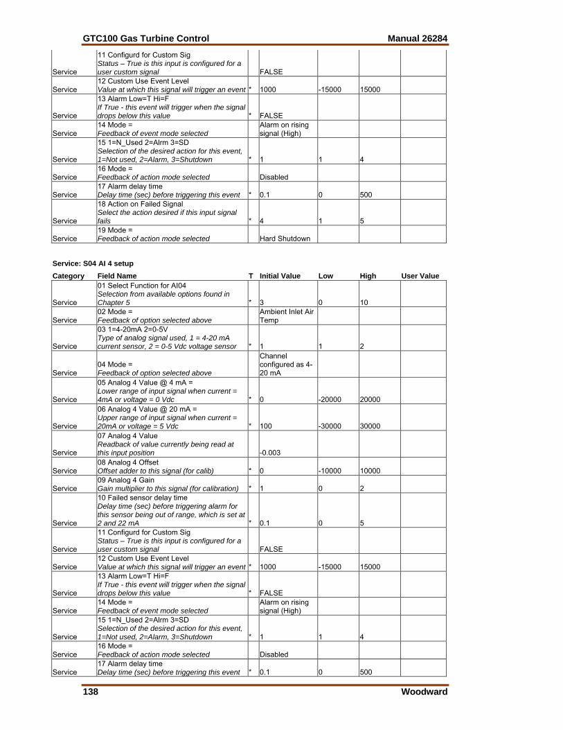
GTC100 Gas Turbine Control Manual 26284
138 Woodward
Service
11 Configurd for Custom Sig Status – True is this input is configured for a user custom signal FALSE
Service 12 Custom Use Event Level Value at which this signal will trigger an event * 1000 -15000 15000
Service
13 Alarm Low=T Hi=F If True - this event will trigger when the signal drops below this value * FALSE
Service 14 Mode = Feedback of event mode selected
Alarm on rising signal (High)
Service
15 1=N_Used 2=Alrm 3=SD Selection of the desired action for this event, 1=Not used, 2=Alarm, 3=Shutdown * 1 1 4
Service 16 Mode = Feedback of action mode selected Disabled
Service 17 Alarm delay time Delay time (sec) before triggering this event * 0.1 0 500
Service
18 Action on Failed Signal Select the action desired if this input signal fails * 4 1 5
Service 19 Mode = Feedback of action mode selected Hard Shutdown
Service: S04 AI 4 setup Category Field Name T Initial Value Low High User Value
Service
01 Select Function for AI04 Selection from available options found in Chapter 5 * 3 0 10
Service 02 Mode = Feedback of option selected above
Ambient Inlet Air Temp
Service
03 1=4-20mA 2=0-5V Type of analog signal used, 1 = 4-20 mA current sensor, 2 = 0-5 Vdc voltage sensor * 1 1 2
Service 04 Mode = Feedback of option selected above
Channel configured as 4-20 mA
Service
05 Analog 4 Value @ 4 mA = Lower range of input signal when current = 4mA or voltage = 0 Vdc * 0 -20000 20000
Service
06 Analog 4 Value @ 20 mA = Upper range of input signal when current = 20mA or voltage = 5 Vdc * 100 -30000 30000
Service
07 Analog 4 Value Readback of value currently being read at this input position -0.003
Service 08 Analog 4 Offset Offset adder to this signal (for calib) * 0 -10000 10000
Service 09 Analog 4 Gain Gain multiplier to this signal (for calibration) * 1 0 2
Service
10 Failed sensor delay time Delay time (sec) before triggering alarm for this sensor being out of range, which is set at 2 and 22 mA * 0.1 0 5
Service
11 Configurd for Custom Sig Status – True is this input is configured for a user custom signal FALSE
Service 12 Custom Use Event Level Value at which this signal will trigger an event * 1000 -15000 15000
Service
13 Alarm Low=T Hi=F If True - this event will trigger when the signal drops below this value * FALSE
Service 14 Mode = Feedback of event mode selected
Alarm on rising signal (High)
Service
15 1=N_Used 2=Alrm 3=SD Selection of the desired action for this event, 1=Not used, 2=Alarm, 3=Shutdown * 1 1 4
Service 16 Mode = Feedback of action mode selected Disabled
Service 17 Alarm delay time Delay time (sec) before triggering this event * 0.1 0 500
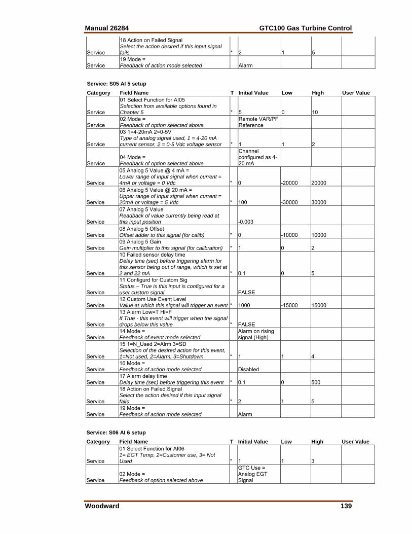
Manual 26284 GTC100 Gas Turbine Control
Woodward 139
Service
18 Action on Failed Signal Select the action desired if this input signal fails * 2 1 5
Service 19 Mode = Feedback of action mode selected Alarm
Service: S05 AI 5 setup Category Field Name T Initial Value Low High User Value
Service
01 Select Function for AI05 Selection from available options found in Chapter 5 * 5 0 10
Service 02 Mode = Feedback of option selected above
Remote VAR/PF Reference
Service
03 1=4-20mA 2=0-5V Type of analog signal used, 1 = 4-20 mA current sensor, 2 = 0-5 Vdc voltage sensor * 1 1 2
Service 04 Mode = Feedback of option selected above
Channel configured as 4-20 mA
Service
05 Analog 5 Value @ 4 mA = Lower range of input signal when current = 4mA or voltage = 0 Vdc * 0 -20000 20000
Service
06 Analog 5 Value @ 20 mA = Upper range of input signal when current = 20mA or voltage = 5 Vdc * 100 -30000 30000
Service
07 Analog 5 Value Readback of value currently being read at this input position -0.003
Service 08 Analog 5 Offset Offset adder to this signal (for calib) * 0 -10000 10000
Service 09 Analog 5 Gain Gain multiplier to this signal (for calibration) * 1 0 2
Service
10 Failed sensor delay time Delay time (sec) before triggering alarm for this sensor being out of range, which is set at 2 and 22 mA * 0.1 0 5
Service
11 Configurd for Custom Sig Status – True is this input is configured for a user custom signal FALSE
Service 12 Custom Use Event Level Value at which this signal will trigger an event * 1000 -15000 15000
Service
13 Alarm Low=T Hi=F If True - this event will trigger when the signal drops below this value * FALSE
Service 14 Mode = Feedback of event mode selected
Alarm on rising signal (High)
Service
15 1=N_Used 2=Alrm 3=SD Selection of the desired action for this event, 1=Not used, 2=Alarm, 3=Shutdown * 1 1 4
Service 16 Mode = Feedback of action mode selected Disabled
Service 17 Alarm delay time Delay time (sec) before triggering this event * 0.1 0 500
Service
18 Action on Failed Signal Select the action desired if this input signal fails * 2 1 5
Service 19 Mode = Feedback of action mode selected Alarm
Service: S06 AI 6 setup Category Field Name T Initial Value Low High User Value
Service
01 Select Function for AI06 1= EGT Temp, 2=Customer use, 3= Not Used * 1 1 3
Service 02 Mode = Feedback of option selected above
GTC Use = Analog EGT Signal
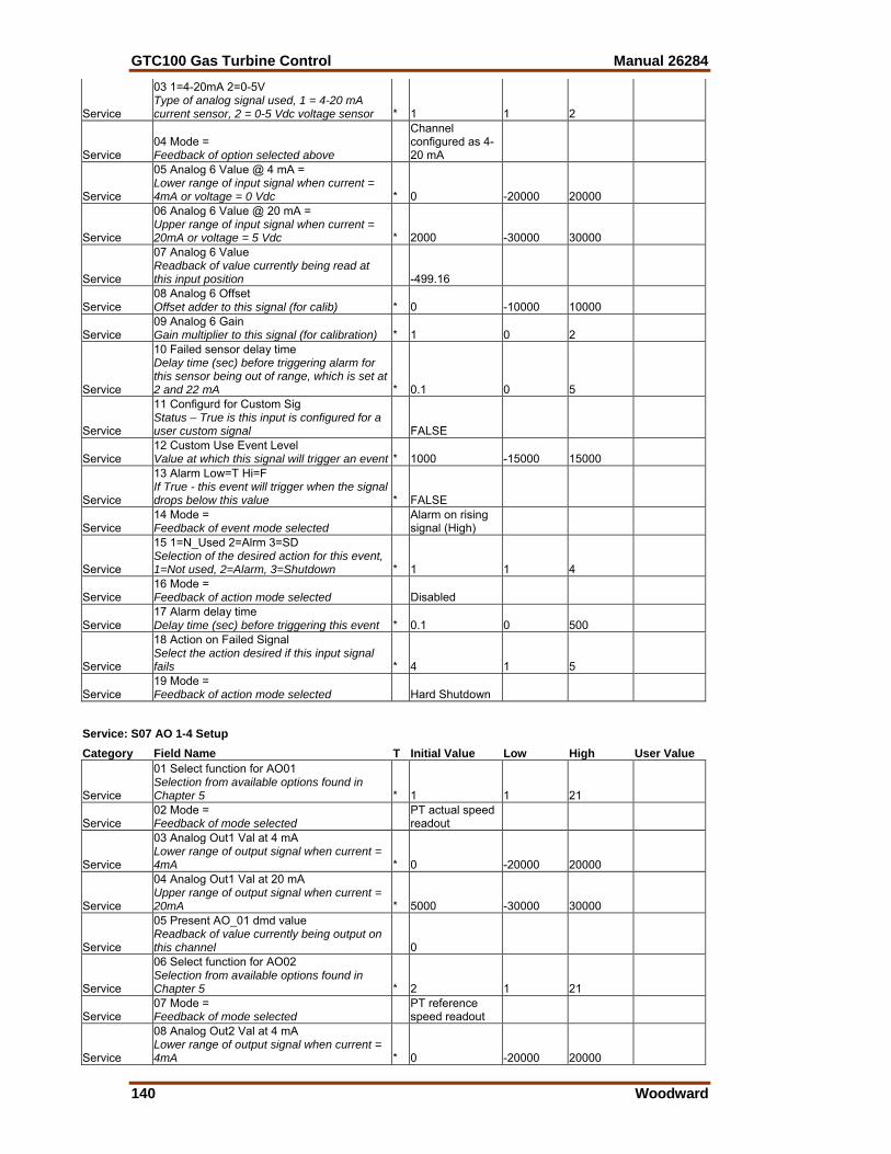
GTC100 Gas Turbine Control Manual 26284
140 Woodward
Service
03 1=4-20mA 2=0-5V Type of analog signal used, 1 = 4-20 mA current sensor, 2 = 0-5 Vdc voltage sensor * 1 1 2
Service 04 Mode = Feedback of option selected above
Channel configured as 4-20 mA
Service
05 Analog 6 Value @ 4 mA = Lower range of input signal when current = 4mA or voltage = 0 Vdc * 0 -20000 20000
Service
06 Analog 6 Value @ 20 mA = Upper range of input signal when current = 20mA or voltage = 5 Vdc * 2000 -30000 30000
Service
07 Analog 6 Value Readback of value currently being read at this input position -499.16
Service 08 Analog 6 Offset Offset adder to this signal (for calib) * 0 -10000 10000
Service 09 Analog 6 Gain Gain multiplier to this signal (for calibration) * 1 0 2
Service
10 Failed sensor delay time Delay time (sec) before triggering alarm for this sensor being out of range, which is set at 2 and 22 mA * 0.1 0 5
Service
11 Configurd for Custom Sig Status – True is this input is configured for a user custom signal FALSE
Service 12 Custom Use Event Level Value at which this signal will trigger an event * 1000 -15000 15000
Service
13 Alarm Low=T Hi=F If True - this event will trigger when the signal drops below this value * FALSE
Service 14 Mode = Feedback of event mode selected
Alarm on rising signal (High)
Service
15 1=N_Used 2=Alrm 3=SD Selection of the desired action for this event, 1=Not used, 2=Alarm, 3=Shutdown * 1 1 4
Service 16 Mode = Feedback of action mode selected Disabled
Service 17 Alarm delay time Delay time (sec) before triggering this event * 0.1 0 500
Service
18 Action on Failed Signal Select the action desired if this input signal fails * 4 1 5
Service 19 Mode = Feedback of action mode selected Hard Shutdown
Service: S07 AO 1-4 Setup Category Field Name T Initial Value Low High User Value
Service
01 Select function for AO01 Selection from available options found in Chapter 5 * 1 1 21
Service 02 Mode = Feedback of mode selected
PT actual speed readout
Service
03 Analog Out1 Val at 4 mA Lower range of output signal when current = 4mA * 0 -20000 20000
Service
04 Analog Out1 Val at 20 mA Upper range of output signal when current = 20mA * 5000 -30000 30000
Service
05 Present AO_01 dmd value Readback of value currently being output on this channel 0
Service
06 Select function for AO02 Selection from available options found in Chapter 5 * 2 1 21
Service 07 Mode = Feedback of mode selected
PT reference speed readout
Service
08 Analog Out2 Val at 4 mA Lower range of output signal when current = 4mA * 0 -20000 20000
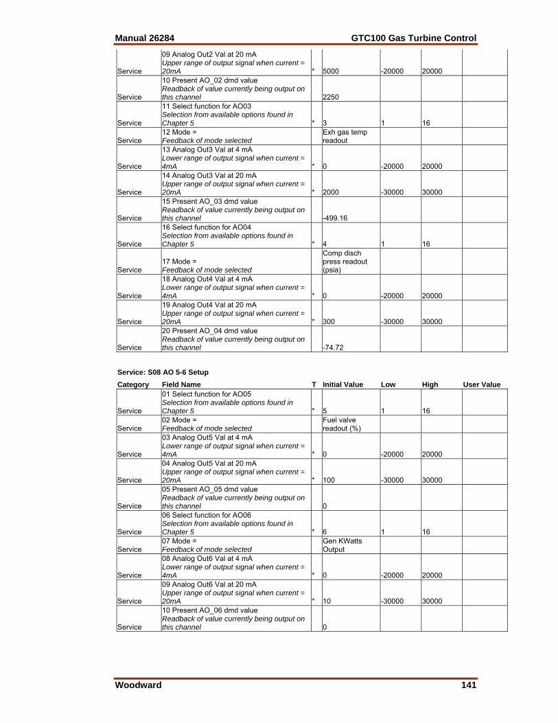
Manual 26284 GTC100 Gas Turbine Control
Woodward 141
Service
09 Analog Out2 Val at 20 mA Upper range of output signal when current = 20mA * 5000 -20000 20000
Service
10 Present AO_02 dmd value Readback of value currently being output on this channel 2250
Service
11 Select function for AO03 Selection from available options found in Chapter 5 * 3 1 16
Service 12 Mode = Feedback of mode selected
Exh gas temp readout
Service
13 Analog Out3 Val at 4 mA Lower range of output signal when current = 4mA * 0 -20000 20000
Service
14 Analog Out3 Val at 20 mA Upper range of output signal when current = 20mA * 2000 -30000 30000
Service
15 Present AO_03 dmd value Readback of value currently being output on this channel -499.16
Service
16 Select function for AO04 Selection from available options found in Chapter 5 * 4 1 16
Service 17 Mode = Feedback of mode selected
Comp disch press readout (psia)
Service
18 Analog Out4 Val at 4 mA Lower range of output signal when current = 4mA * 0 -20000 20000
Service
19 Analog Out4 Val at 20 mA Upper range of output signal when current = 20mA * 300 -30000 30000
Service
20 Present AO_04 dmd value Readback of value currently being output on this channel -74.72
Service: S08 AO 5-6 Setup Category Field Name T Initial Value Low High User Value
Service
01 Select function for AO05 Selection from available options found in Chapter 5 * 5 1 16
Service 02 Mode = Feedback of mode selected
Fuel valve readout (%)
Service
03 Analog Out5 Val at 4 mA Lower range of output signal when current = 4mA * 0 -20000 20000
Service
04 Analog Out5 Val at 20 mA Upper range of output signal when current = 20mA * 100 -30000 30000
Service
05 Present AO_05 dmd value Readback of value currently being output on this channel 0
Service
06 Select function for AO06 Selection from available options found in Chapter 5 * 6 1 16
Service 07 Mode = Feedback of mode selected
Gen KWatts Output
Service
08 Analog Out6 Val at 4 mA Lower range of output signal when current = 4mA * 0 -20000 20000
Service
09 Analog Out6 Val at 20 mA Upper range of output signal when current = 20mA * 10 -30000 30000
Service
10 Present AO_06 dmd value Readback of value currently being output on this channel 0
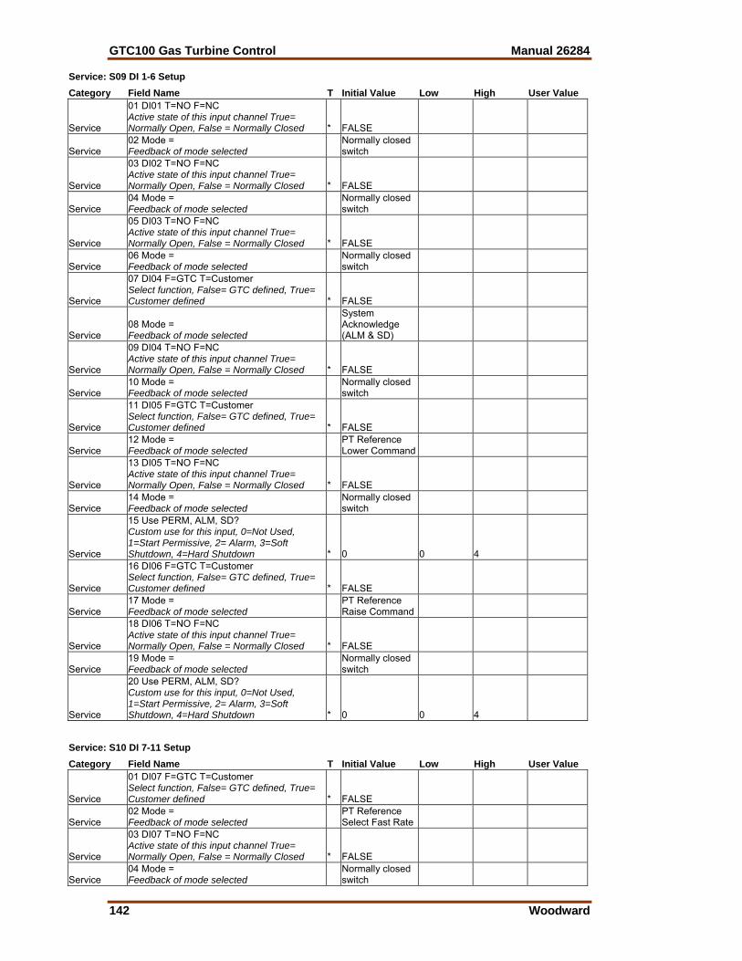
GTC100 Gas Turbine Control Manual 26284
142 Woodward
Service: S09 DI 1-6 Setup Category Field Name T Initial Value Low High User Value
Service
01 DI01 T=NO F=NC Active state of this input channel True= Normally Open, False = Normally Closed * FALSE
Service 02 Mode = Feedback of mode selected
Normally closed switch
Service
03 DI02 T=NO F=NC Active state of this input channel True= Normally Open, False = Normally Closed * FALSE
Service 04 Mode = Feedback of mode selected
Normally closed switch
Service
05 DI03 T=NO F=NC Active state of this input channel True= Normally Open, False = Normally Closed * FALSE
Service 06 Mode = Feedback of mode selected
Normally closed switch
Service
07 DI04 F=GTC T=Customer Select function, False= GTC defined, True= Customer defined * FALSE
Service 08 Mode = Feedback of mode selected
System Acknowledge (ALM & SD)
Service
09 DI04 T=NO F=NC Active state of this input channel True= Normally Open, False = Normally Closed * FALSE
Service 10 Mode = Feedback of mode selected
Normally closed switch
Service
11 DI05 F=GTC T=Customer Select function, False= GTC defined, True= Customer defined * FALSE
Service 12 Mode = Feedback of mode selected
PT Reference Lower Command
Service
13 DI05 T=NO F=NC Active state of this input channel True= Normally Open, False = Normally Closed * FALSE
Service 14 Mode = Feedback of mode selected
Normally closed switch
Service
15 Use PERM, ALM, SD? Custom use for this input, 0=Not Used, 1=Start Permissive, 2= Alarm, 3=Soft Shutdown, 4=Hard Shutdown * 0 0 4
Service
16 DI06 F=GTC T=Customer Select function, False= GTC defined, True= Customer defined * FALSE
Service 17 Mode = Feedback of mode selected
PT Reference Raise Command
Service
18 DI06 T=NO F=NC Active state of this input channel True= Normally Open, False = Normally Closed * FALSE
Service 19 Mode = Feedback of mode selected
Normally closed switch
Service
20 Use PERM, ALM, SD? Custom use for this input, 0=Not Used, 1=Start Permissive, 2= Alarm, 3=Soft Shutdown, 4=Hard Shutdown * 0 0 4
Service: S10 DI 7-11 Setup Category Field Name T Initial Value Low High User Value
Service
01 DI07 F=GTC T=Customer Select function, False= GTC defined, True= Customer defined * FALSE
Service 02 Mode = Feedback of mode selected
PT Reference Select Fast Rate
Service
03 DI07 T=NO F=NC Active state of this input channel True= Normally Open, False = Normally Closed * FALSE
Service 04 Mode = Feedback of mode selected
Normally closed switch
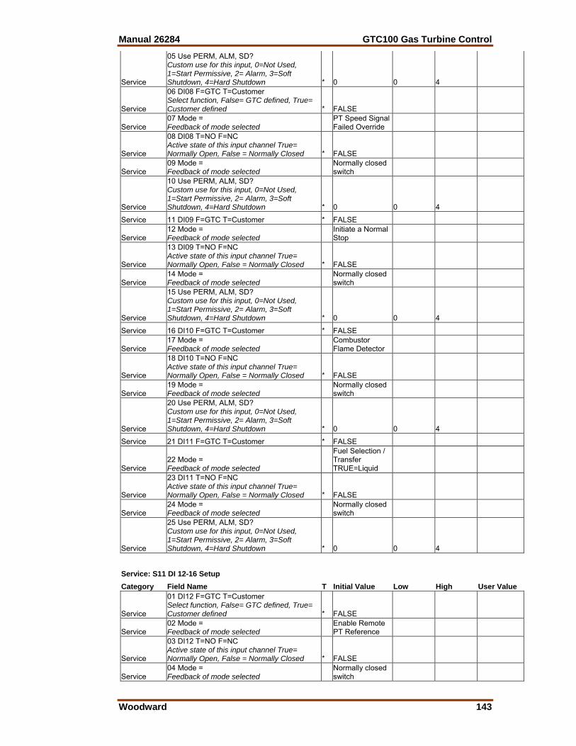
Manual 26284 GTC100 Gas Turbine Control
Woodward 143
Service
05 Use PERM, ALM, SD? Custom use for this input, 0=Not Used, 1=Start Permissive, 2= Alarm, 3=Soft Shutdown, 4=Hard Shutdown * 0 0 4
Service
06 DI08 F=GTC T=Customer Select function, False= GTC defined, True= Customer defined * FALSE
Service 07 Mode = Feedback of mode selected
PT Speed Signal Failed Override
Service
08 DI08 T=NO F=NC Active state of this input channel True= Normally Open, False = Normally Closed * FALSE
Service 09 Mode = Feedback of mode selected
Normally closed switch
Service
10 Use PERM, ALM, SD? Custom use for this input, 0=Not Used, 1=Start Permissive, 2= Alarm, 3=Soft Shutdown, 4=Hard Shutdown * 0 0 4
Service 11 DI09 F=GTC T=Customer * FALSE
Service 12 Mode = Feedback of mode selected
Initiate a Normal Stop
Service
13 DI09 T=NO F=NC Active state of this input channel True= Normally Open, False = Normally Closed * FALSE
Service 14 Mode = Feedback of mode selected
Normally closed switch
Service
15 Use PERM, ALM, SD? Custom use for this input, 0=Not Used, 1=Start Permissive, 2= Alarm, 3=Soft Shutdown, 4=Hard Shutdown * 0 0 4
Service 16 DI10 F=GTC T=Customer * FALSE
Service 17 Mode = Feedback of mode selected
Combustor Flame Detector
Service
18 DI10 T=NO F=NC Active state of this input channel True= Normally Open, False = Normally Closed * FALSE
Service 19 Mode = Feedback of mode selected
Normally closed switch
Service
20 Use PERM, ALM, SD? Custom use for this input, 0=Not Used, 1=Start Permissive, 2= Alarm, 3=Soft Shutdown, 4=Hard Shutdown * 0 0 4
Service 21 DI11 F=GTC T=Customer * FALSE
Service 22 Mode = Feedback of mode selected
Fuel Selection / Transfer TRUE=Liquid
Service
23 DI11 T=NO F=NC Active state of this input channel True= Normally Open, False = Normally Closed * FALSE
Service 24 Mode = Feedback of mode selected
Normally closed switch
Service
25 Use PERM, ALM, SD? Custom use for this input, 0=Not Used, 1=Start Permissive, 2= Alarm, 3=Soft Shutdown, 4=Hard Shutdown * 0 0 4
Service: S11 DI 12-16 Setup Category Field Name T Initial Value Low High User Value
Service
01 DI12 F=GTC T=Customer Select function, False= GTC defined, True= Customer defined * FALSE
Service 02 Mode = Feedback of mode selected
Enable Remote PT Reference
Service
03 DI12 T=NO F=NC Active state of this input channel True= Normally Open, False = Normally Closed * FALSE
Service 04 Mode = Feedback of mode selected
Normally closed switch
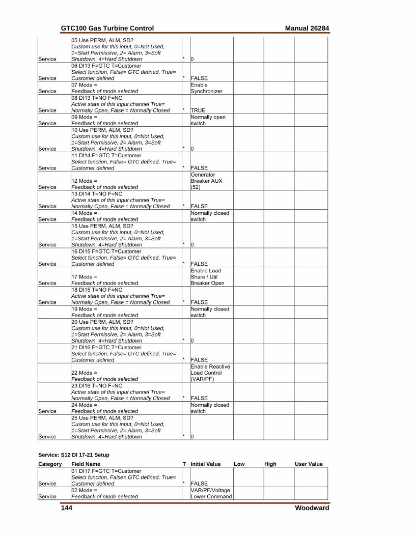
GTC100 Gas Turbine Control Manual 26284
144 Woodward
Service
05 Use PERM, ALM, SD? Custom use for this input, 0=Not Used, 1=Start Permissive, 2= Alarm, 3=Soft Shutdown, 4=Hard Shutdown * 0
Service
06 DI13 F=GTC T=Customer Select function, False= GTC defined, True= Customer defined * FALSE
Service 07 Mode = Feedback of mode selected
Enable Synchronizer
Service
08 DI13 T=NO F=NC Active state of this input channel True= Normally Open, False = Normally Closed * TRUE
Service 09 Mode = Feedback of mode selected
Normally open switch
Service
10 Use PERM, ALM, SD? Custom use for this input, 0=Not Used, 1=Start Permissive, 2= Alarm, 3=Soft Shutdown, 4=Hard Shutdown * 0
Service
11 DI14 F=GTC T=Customer Select function, False= GTC defined, True= Customer defined * FALSE
Service 12 Mode = Feedback of mode selected
Generator Breaker AUX (52)
Service
13 DI14 T=NO F=NC Active state of this input channel True= Normally Open, False = Normally Closed * FALSE
Service 14 Mode = Feedback of mode selected
Normally closed switch
Service
15 Use PERM, ALM, SD? Custom use for this input, 0=Not Used, 1=Start Permissive, 2= Alarm, 3=Soft Shutdown, 4=Hard Shutdown * 0
Service
16 DI15 F=GTC T=Customer Select function, False= GTC defined, True= Customer defined * FALSE
Service 17 Mode = Feedback of mode selected
Enable Load Share / Util Breaker Open
Service
18 DI15 T=NO F=NC Active state of this input channel True= Normally Open, False = Normally Closed * FALSE
19 Mode = Feedback of mode selected
Normally closed switch
20 Use PERM, ALM, SD? Custom use for this input, 0=Not Used, 1=Start Permissive, 2= Alarm, 3=Soft Shutdown, 4=Hard Shutdown * 0
21 DI16 F=GTC T=Customer Select function, False= GTC defined, True= Customer defined * FALSE
22 Mode = Feedback of mode selected
Enable Reactive Load Control (VAR/PF)
23 DI16 T=NO F=NC Active state of this input channel True= Normally Open, False = Normally Closed * FALSE
Service 24 Mode = Feedback of mode selected
Normally closed switch
Service
25 Use PERM, ALM, SD? Custom use for this input, 0=Not Used, 1=Start Permissive, 2= Alarm, 3=Soft Shutdown, 4=Hard Shutdown * 0
Service: S12 DI 17-21 Setup Category Field Name T Initial Value Low High User Value
Service
01 DI17 F=GTC T=Customer Select function, False= GTC defined, True= Customer defined * FALSE
Service 02 Mode = Feedback of mode selected
VAR/PF/Voltage Lower Command
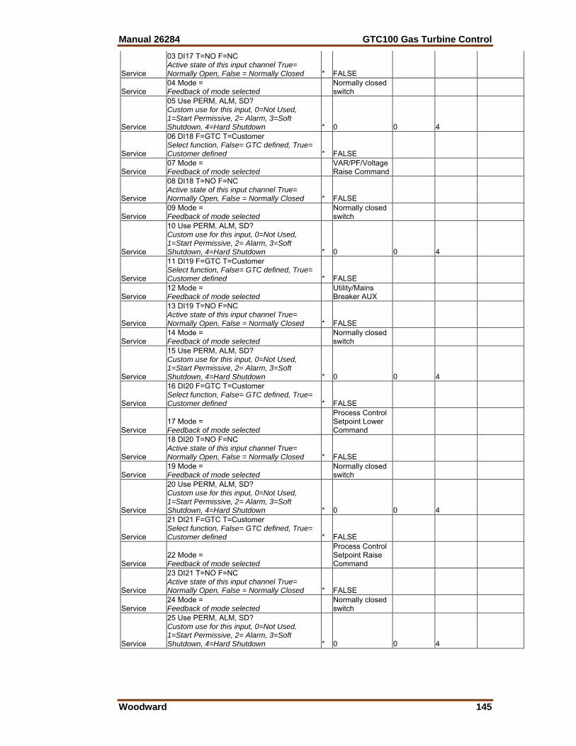
Manual 26284 GTC100 Gas Turbine Control
Woodward 145
Service
03 DI17 T=NO F=NC Active state of this input channel True= Normally Open, False = Normally Closed * FALSE
Service 04 Mode = Feedback of mode selected
Normally closed switch
Service
05 Use PERM, ALM, SD? Custom use for this input, 0=Not Used, 1=Start Permissive, 2= Alarm, 3=Soft Shutdown, 4=Hard Shutdown * 0 0 4
Service
06 DI18 F=GTC T=Customer Select function, False= GTC defined, True= Customer defined * FALSE
Service 07 Mode = Feedback of mode selected
VAR/PF/Voltage Raise Command
Service
08 DI18 T=NO F=NC Active state of this input channel True= Normally Open, False = Normally Closed * FALSE
Service 09 Mode = Feedback of mode selected
Normally closed switch
Service
10 Use PERM, ALM, SD? Custom use for this input, 0=Not Used, 1=Start Permissive, 2= Alarm, 3=Soft Shutdown, 4=Hard Shutdown * 0 0 4
Service
11 DI19 F=GTC T=Customer Select function, False= GTC defined, True= Customer defined * FALSE
Service 12 Mode = Feedback of mode selected
Utility/Mains Breaker AUX
Service
13 DI19 T=NO F=NC Active state of this input channel True= Normally Open, False = Normally Closed * FALSE
Service 14 Mode = Feedback of mode selected
Normally closed switch
Service
15 Use PERM, ALM, SD? Custom use for this input, 0=Not Used, 1=Start Permissive, 2= Alarm, 3=Soft Shutdown, 4=Hard Shutdown * 0 0 4
Service
16 DI20 F=GTC T=Customer Select function, False= GTC defined, True= Customer defined * FALSE
Service 17 Mode = Feedback of mode selected
Process Control Setpoint Lower Command
Service
18 DI20 T=NO F=NC Active state of this input channel True= Normally Open, False = Normally Closed * FALSE
Service 19 Mode = Feedback of mode selected
Normally closed switch
Service
20 Use PERM, ALM, SD? Custom use for this input, 0=Not Used, 1=Start Permissive, 2= Alarm, 3=Soft Shutdown, 4=Hard Shutdown * 0 0 4
Service
21 DI21 F=GTC T=Customer Select function, False= GTC defined, True= Customer defined * FALSE
Service 22 Mode = Feedback of mode selected
Process Control Setpoint Raise Command
Service
23 DI21 T=NO F=NC Active state of this input channel True= Normally Open, False = Normally Closed * FALSE
Service 24 Mode = Feedback of mode selected
Normally closed switch
Service
25 Use PERM, ALM, SD? Custom use for this input, 0=Not Used, 1=Start Permissive, 2= Alarm, 3=Soft Shutdown, 4=Hard Shutdown * 0 0 4
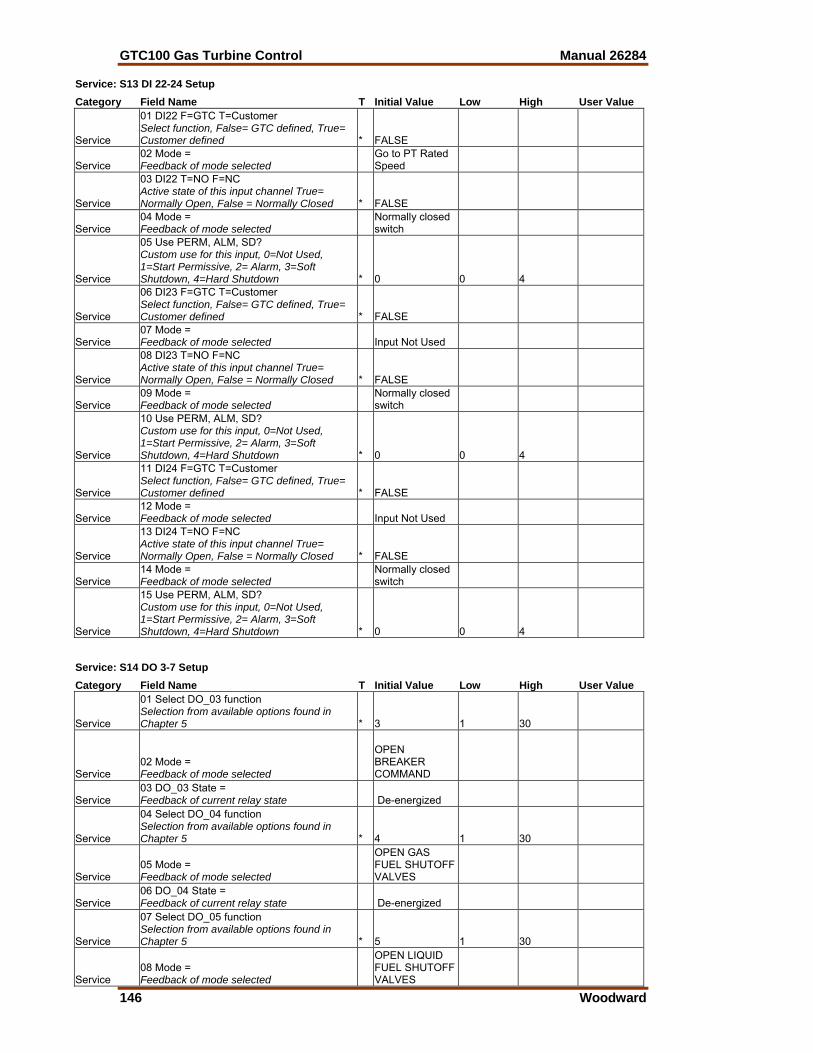
GTC100 Gas Turbine Control Manual 26284
146 Woodward
Service: S13 DI 22-24 Setup Category Field Name T Initial Value Low High User Value
Service
01 DI22 F=GTC T=Customer Select function, False= GTC defined, True= Customer defined * FALSE
Service 02 Mode = Feedback of mode selected
Go to PT Rated Speed
Service
03 DI22 T=NO F=NC Active state of this input channel True= Normally Open, False = Normally Closed * FALSE
Service 04 Mode = Feedback of mode selected
Normally closed switch
Service
05 Use PERM, ALM, SD? Custom use for this input, 0=Not Used, 1=Start Permissive, 2= Alarm, 3=Soft Shutdown, 4=Hard Shutdown * 0 0 4
Service
06 DI23 F=GTC T=Customer Select function, False= GTC defined, True= Customer defined * FALSE
Service 07 Mode = Feedback of mode selected Input Not Used
Service
08 DI23 T=NO F=NC Active state of this input channel True= Normally Open, False = Normally Closed * FALSE
Service 09 Mode = Feedback of mode selected
Normally closed switch
Service
10 Use PERM, ALM, SD? Custom use for this input, 0=Not Used, 1=Start Permissive, 2= Alarm, 3=Soft Shutdown, 4=Hard Shutdown * 0 0 4
Service
11 DI24 F=GTC T=Customer Select function, False= GTC defined, True= Customer defined * FALSE
Service 12 Mode = Feedback of mode selected Input Not Used
Service
13 DI24 T=NO F=NC Active state of this input channel True= Normally Open, False = Normally Closed * FALSE
Service 14 Mode = Feedback of mode selected
Normally closed switch
Service
15 Use PERM, ALM, SD? Custom use for this input, 0=Not Used, 1=Start Permissive, 2= Alarm, 3=Soft Shutdown, 4=Hard Shutdown * 0 0 4
Service: S14 DO 3-7 Setup Category Field Name T Initial Value Low High User Value
Service
01 Select DO_03 function Selection from available options found in Chapter 5 * 3 1 30
Service 02 Mode = Feedback of mode selected
OPEN BREAKER COMMAND
Service 03 DO_03 State = Feedback of current relay state De-energized
Service
04 Select DO_04 function Selection from available options found in Chapter 5 * 4 1 30
Service 05 Mode = Feedback of mode selected
OPEN GAS FUEL SHUTOFF VALVES
Service 06 DO_04 State = Feedback of current relay state De-energized
Service
07 Select DO_05 function Selection from available options found in Chapter 5 * 5 1 30
Service 08 Mode = Feedback of mode selected
OPEN LIQUID FUEL SHUTOFF VALVES
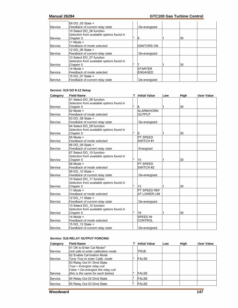
Manual 26284 GTC100 Gas Turbine Control
Woodward 147
Service 09 DO_05 State = Feedback of current relay state De-energized
Service
10 Select DO_06 function Selection from available options found in Chapter 5 * 6 1 30
Service 11 Mode = Feedback of mode selected IGNITORS ON
Service 12 DO_06 State = Feedback of current relay state De-energized
Service
13 Select DO_07 function Selection from available options found in Chapter 5 * 7 1 30
Service 14 Mode = Feedback of mode selected
STARTER ENGAGED
Service 15 DO_07 State = Feedback of current relay state De-energized
Service: S15 DO 8-12 Setup Category Field Name T Initial Value Low High User Value
Service
01 Select DO_08 function Selection from available options found in Chapter 5 * 8 1 30
Service 02 Mode = Feedback of mode selected
ALARM/HORN OUTPUT
Service 03 DO_08 State = Feedback of current relay state De-energized
Service
04 Select DO_09 function Selection from available options found in Chapter 5 * 9 1 30
Service 05 Mode = Feedback of mode selected
PT SPEED SWITCH #1
Service 06 DO_09 State = Feedback of current relay state Energized
Service
07 Select DO_10 function Selection from available options found in Chapter 5 * 10 1 30
Service 08 Mode = Feedback of mode selected
PT SPEED SWITCH #2
Service 09 DO_10 State = Feedback of current relay state De-energized
Service
10 Select DO_11 function Selection from available options found in Chapter 5 * 13 1 30
Service 11 Mode = Feedback of mode selected
PT SPEED REF AT LOWER LIM
Service 12 DO_11 State = Feedback of current relay state De-energized
Service
13 Select DO_12 function Selection from available options found in Chapter 5 * 18 1 30
Service 14 Mode = Feedback of mode selected
SPEED IN CONTROL
Service 15 DO_12 State = Feedback of current relay state De-energized
Service: S16 RELAY OUTPUT FORCING Category Field Name T Initial Value Low High User Value
Service 01 OK to Enter Cal Mode? Unit safe to enter calibration mode TRUE
Service 02 Enable Cal bration Mode Tune True to enter Calib. mode * FALSE
Service
03 Relay Out 01 Dmd State True = Energize relay coil False = De-energize the relay coil (this is the same for each below) * FALSE
Service 04 Relay Out 02 Dmd State * FALSE
Service 05 Relay Out 03 Dmd State * FALSE
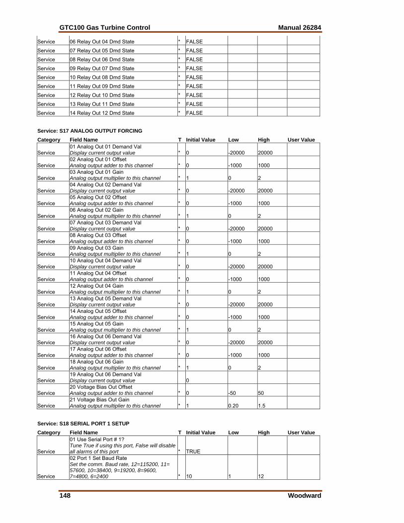
GTC100 Gas Turbine Control Manual 26284
148 Woodward
Service 06 Relay Out 04 Dmd State * FALSE
Service 07 Relay Out 05 Dmd State * FALSE
Service 08 Relay Out 06 Dmd State * FALSE
Service 09 Relay Out 07 Dmd State * FALSE
Service 10 Relay Out 08 Dmd State * FALSE
Service 11 Relay Out 09 Dmd State * FALSE
Service 12 Relay Out 10 Dmd State * FALSE
Service 13 Relay Out 11 Dmd State * FALSE
Service 14 Relay Out 12 Dmd State * FALSE
Service: S17 ANALOG OUTPUT FORCING Category Field Name T Initial Value Low High User Value
Service 01 Analog Out 01 Demand Val Display current output value * 0 -20000 20000
Service 02 Analog Out 01 Offset Analog output adder to this channel * 0 -1000 1000
Service 03 Analog Out 01 Gain Analog output multiplier to this channel * 1 0 2
Service 04 Analog Out 02 Demand Val Display current output value * 0 -20000 20000
Service 05 Analog Out 02 Offset Analog output adder to this channel * 0 -1000 1000
Service 06 Analog Out 02 Gain Analog output multiplier to this channel * 1 0 2
Service 07 Analog Out 03 Demand Val Display current output value * 0 -20000 20000
Service 08 Analog Out 03 Offset Analog output adder to this channel * 0 -1000 1000
Service 09 Analog Out 03 Gain Analog output multiplier to this channel * 1 0 2
Service 10 Analog Out 04 Demand Val Display current output value * 0 -20000 20000
Service 11 Analog Out 04 Offset Analog output adder to this channel * 0 -1000 1000
Service 12 Analog Out 04 Gain Analog output multiplier to this channel * 1 0 2
Service 13 Analog Out 05 Demand Val Display current output value * 0 -20000 20000
Service 14 Analog Out 05 Offset Analog output adder to this channel * 0 -1000 1000
Service 15 Analog Out 05 Gain Analog output multiplier to this channel * 1 0 2
Service 16 Analog Out 06 Demand Val Display current output value * 0 -20000 20000
Service 17 Analog Out 06 Offset Analog output adder to this channel * 0 -1000 1000
Service 18 Analog Out 06 Gain Analog output multiplier to this channel * 1 0 2
Service 19 Analog Out 06 Demand Val Display current output value 0
Service 20 Voltage Bias Out Offset Analog output adder to this channel * 0 -50 50
Service 21 Voltage Bias Out Gain Analog output multiplier to this channel * 1 0.20 1.5
Service: S18 SERIAL PORT 1 SETUP Category Field Name T Initial Value Low High User Value
Service
01 Use Serial Port # 1? Tune True if using this port, False will disable all alarms of this port * TRUE
Service
02 Port 1 Set Baud Rate Set the comm. Baud rate, 12=115200, 11= 57600, 10=38400, 9=19200, 8=9600, 7=4800, 6=2400 * 10 1 12
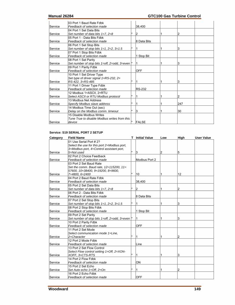
Manual 26284 GTC100 Gas Turbine Control
Woodward 149
Service 03 Port 1 Baud Rate Fdbk Feedback of selection made 38,400
Service 04 Port 1 Set Data Bits Set number of data bits 1=7, 2=8 * 2 1 2
Service 05 Port 1 - Data Bits Fdbk Feedback of selection made 8 Data Bits
Service 06 Port 1 Set Stop Bits Set number of stop bits 1=1, 2=2, 3=1.5 * 1 1 3
Service 07 Port 1 Stop Bits Fdbk Feedback of selection made 1 Stop Bit
Service 08 Port 1 Set Parity Set number of stop bits 1=off, 2=odd, 3=even * 1 1 3
Service 09 Port 1 Parity Fdbk Feedback of selection made OFF
Service
10 Port 1 Set Driver Type Set type of driver signal 1=RS-232, 2= RS-422, 3=RS-485 * 1 1 3
Service 11 Port 1 Driver Type Fdbk Feedback of selection made RS-232
Service 12 Modbus 1=ASCII, 2=RTU Select ASCII or RTU Modbus protocol * 1 1 2
Service 13 Modbus Net Address Specify Modbus slave address * 1 1 247
Service 14 Modbus Time Out (sec) Delay on the Modbus comm. timeout * 3 1 30
Service
15 Disable Modbus Writes Tune True to disable Modbus writes from this device * FALSE
Service: S19 SERIAL PORT 2 SETUP Category Field Name T Initial Value Low High User Value
Service
01 Use Serial Port # 2? Select the use for this port 2=Modbus port, 3=Modbus port, 4=Control assistant port, 5=Not used * 3 2 5
Service 02 Port 2 Choice Feedback Feedback of selection made Modbus Port 2
Service
03 Port 2 Set Baud Rate Set the comm. Baud rate, 12=115200, 11= 57600, 10=38400, 9=19200, 8=9600, 7=4800, 6=2400 * 10 1 12
Service 04 Port 2 Baud Rate Fdbk Feedback of selection made 38,400
Service 05 Port 2 Set Data Bits Set number of data bits 1=7, 2=8 * 2 1 2
Service 06 Port 2 - Data Bits Fdbk Feedback of selection made 8 Data Bits
Service 07 Port 2 Set Stop Bits Set number of stop bits 1=1, 2=2, 3=1.5 * 1 1 3
Service 08 Port 2 Stop Bits Fdbk Feedback of selection made 1 Stop Bit
Service 09 Port 2 Set Parity Set number of stop bits 1=off, 2=odd, 3=even * 1 1 3
Service 10 Port 2 Parity Fdbk Feedback of selection made OFF
Service
11 Port 2 Set Mode Select communication mode 1=Line, 2=Character * 1 1 2
Service 12 Port 2 Mode Fdbk Feedback of selection made Line
Service
13 Port 2 Set Flow Control Select Flow control setting 1=Off, 2=XON-XOFF, 3=CTS-RTS * 1 1 3
Service 14 Port 2 Flow Fdbk Feedback of selection made ON
Service 15 Port 2 Set Echo Set Auto echo 1=Off, 2=On * 1 1 2
Service 16 Port 2 Echo Fdbk Feedback of selection made OFF
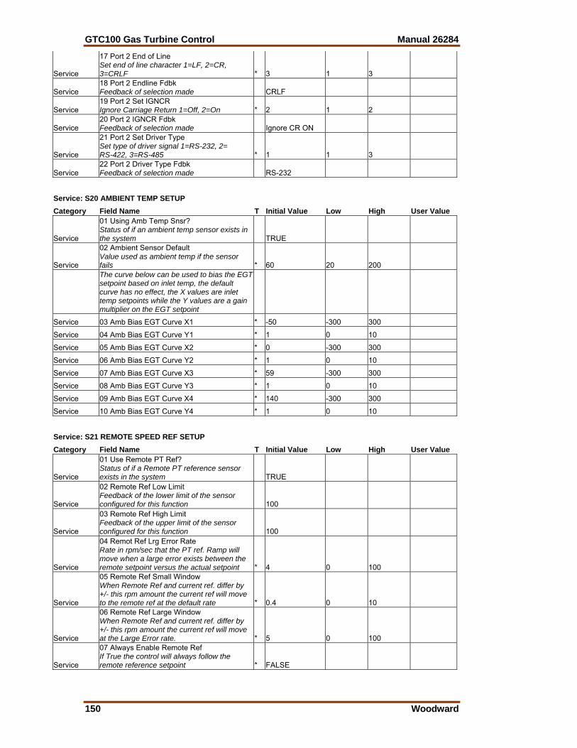
GTC100 Gas Turbine Control Manual 26284
150 Woodward
Service
17 Port 2 End of Line Set end of line character 1=LF, 2=CR, 3=CRLF * 3 1 3
Service 18 Port 2 Endline Fdbk Feedback of selection made CRLF
Service 19 Port 2 Set IGNCR Ignore Carriage Return 1=Off, 2=On * 2 1 2
Service 20 Port 2 IGNCR Fdbk Feedback of selection made Ignore CR ON
Service
21 Port 2 Set Driver Type Set type of driver signal 1=RS-232, 2= RS-422, 3=RS-485 * 1 1 3
Service 22 Port 2 Driver Type Fdbk Feedback of selection made RS-232
Service: S20 AMBIENT TEMP SETUP Category Field Name T Initial Value Low High User Value
Service
01 Using Amb Temp Snsr? Status of if an ambient temp sensor exists in the system TRUE
Service
02 Ambient Sensor Default Value used as ambient temp if the sensor fails * 60 20 200
The curve below can be used to bias the EGT setpoint based on inlet temp, the default curve has no effect, the X values are inlet temp setpoints while the Y values are a gain multiplier on the EGT setpoint
Service 03 Amb Bias EGT Curve X1 * -50 -300 300
Service 04 Amb Bias EGT Curve Y1 * 1 0 10
Service 05 Amb Bias EGT Curve X2 * 0 -300 300
Service 06 Amb Bias EGT Curve Y2 * 1 0 10
Service 07 Amb Bias EGT Curve X3 * 59 -300 300
Service 08 Amb Bias EGT Curve Y3 * 1 0 10
Service 09 Amb Bias EGT Curve X4 * 140 -300 300
Service 10 Amb Bias EGT Curve Y4 * 1 0 10
Service: S21 REMOTE SPEED REF SETUP Category Field Name T Initial Value Low High User Value
Service
01 Use Remote PT Ref? Status of if a Remote PT reference sensor exists in the system TRUE
Service
02 Remote Ref Low Limit Feedback of the lower limit of the sensor configured for this function 100
Service
03 Remote Ref High Limit Feedback of the upper limit of the sensor configured for this function 100
Service
04 Remot Ref Lrg Error Rate Rate in rpm/sec that the PT ref. Ramp will move when a large error exists between the remote setpoint versus the actual setpoint * 4 0 100
Service
05 Remote Ref Small Window When Remote Ref and current ref. differ by +/- this rpm amount the current ref will move to the remote ref at the default rate * 0.4 0 10
Service
06 Remote Ref Large Window When Remote Ref and current ref. differ by +/- this rpm amount the current ref will move at the Large Error rate. * 5 0 100
Service
07 Always Enable Remote Ref If True the control will always follow the remote reference setpoint * FALSE
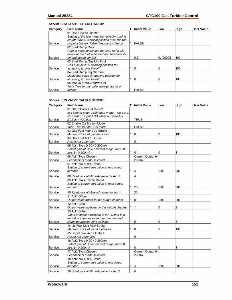
Manual 26284 GTC100 Gas Turbine Control
Woodward 151
Service: S22 START / LITEOFF SETUP Category Field Name T Initial Value Low High User Value
Service
01 Use Electric Liteoff? Setting of the fuel metering valve for turbine lite-off, True=Electrical position (use min fuel setpoint below), False=Mechanical lite-off * FALSE
Service
02 Start Ramp Rate Rate in percent/sec that the start ramp will increase the fuel valve demand between lite-off and speed control * 0.3 0.100006 100
Service
03 Start Ramp Gas Min Fuel Gas fuel valve % opening position for achieving turbine lite-off * 0 0 100
Service
04 Start Ramp Liq Min Fuel Liquid fuel valve % opening position for achieving turbine lite-off * 0 0 100
Service
05 Manual Crank/Starter ON Tune True to manually engage starter on turbine * FALSE
Service: S23 VALVE CALIB & STROKE Category Field Name T Initial Value Low High User Value
Service
01 OK to Enter Cal Mode? Is it safe to enter Calibration mode – No SD’s, No start/run input AND either no speed or EGT is < 400 deg TRUE
Service 02 Enable Cal bration Mode Tune True to enter Cal mode * FALSE
Service 03 Gas Fuel Metr VLV Stroke Manual stroke of gas fuel valve * 0 0 100
Service 04 Gas Fuel Act 1 Output Actual Act 1 demand 0
Service
05 Act1 Type 0-20 / 0-200mA Select type of Driver current range, 0=0-20 mA, 1= 0-200mA * 0 0 1
Service 06 Act1 Type Chosen Feedback of mode selected
Current Output 0-20 mA
Service
07 Act1 mA at 0% Dmnd Setting of current mA value at min output demand * 4 -200 200
Service 08 Readback of Min mA value for Act 1 4
Service
09 Act1 mA at 100% Dmnd Setting of current mA value at max output demand * 20 -200 200
Service 10 Readback of Max mA value for Act 1 20
Service 11 Act1 Offset Output value adder to this output channel * 0 -200 200
Service 12 Act1 Gain Output value multiplier to this output channel * 1 0 2
Service
13 Act1 Dither Value of dither amplitude in mA. Dither is a +/- value superimposed over the demand signal to prevent valve sticking * 0 0 3
Service 14 Liq Fuel Metr VLV Stroke Manual stroke of liquid fuel valve * 0 0 100
Service 15 Liquid Fuel Act 2 Output Actual Act 2 demand 0
Service
16 Act2 Type 0-20 / 0-200mA Select type of Driver current range, 0=0-20 mA, 1= 0-200mA * 0 0 1
Service 17 Act2 Type Chosen Feedback of mode selected
Current Output 0-20 mA
Service
18 Act2 mA at 0% Dmnd Setting of current mA value at min output demand * 4 -200 200
Service 19 Readback of Min mA value for Act 2 4
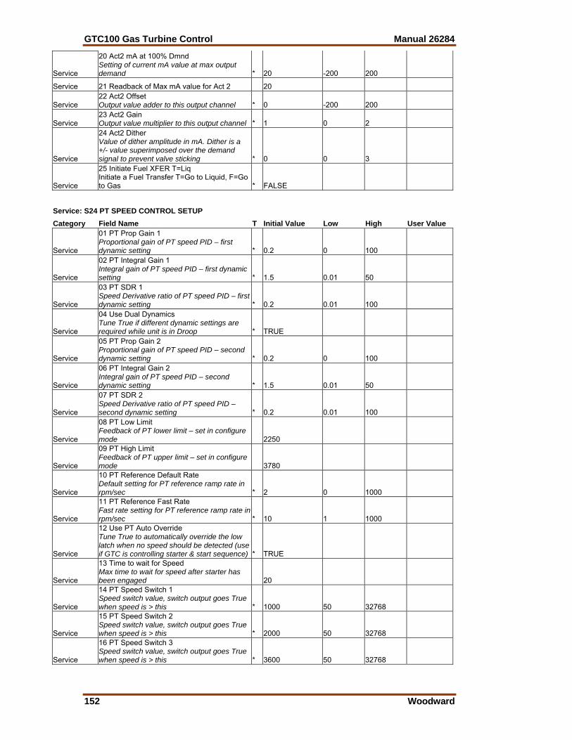
GTC100 Gas Turbine Control Manual 26284
152 Woodward
Service
20 Act2 mA at 100% Dmnd Setting of current mA value at max output demand * 20 -200 200
Service 21 Readback of Max mA value for Act 2 20
Service 22 Act2 Offset Output value adder to this output channel * 0 -200 200
Service 23 Act2 Gain Output value multiplier to this output channel * 1 0 2
Service
24 Act2 Dither Value of dither amplitude in mA. Dither is a +/- value superimposed over the demand signal to prevent valve sticking * 0 0 3
Service
25 Initiate Fuel XFER T=Liq Initiate a Fuel Transfer T=Go to Liquid, F=Go to Gas * FALSE
Service: S24 PT SPEED CONTROL SETUP Category Field Name T Initial Value Low High User Value
Service
01 PT Prop Gain 1 Proportional gain of PT speed PID – first dynamic setting * 0.2 0 100
Service
02 PT Integral Gain 1 Integral gain of PT speed PID – first dynamic setting * 1.5 0.01 50
Service
03 PT SDR 1 Speed Derivative ratio of PT speed PID – first dynamic setting * 0.2 0.01 100
Service
04 Use Dual Dynamics Tune True if different dynamic settings are required while unit is in Droop * TRUE
Service
05 PT Prop Gain 2 Proportional gain of PT speed PID – second dynamic setting * 0.2 0 100
Service
06 PT Integral Gain 2 Integral gain of PT speed PID – second dynamic setting * 1.5 0.01 50
Service
07 PT SDR 2 Speed Derivative ratio of PT speed PID – second dynamic setting * 0.2 0.01 100
Service
08 PT Low Limit Feedback of PT lower limit – set in configure mode 2250
Service
09 PT High Limit Feedback of PT upper limit – set in configure mode 3780
Service
10 PT Reference Default Rate Default setting for PT reference ramp rate in rpm/sec * 2 0 1000
Service
11 PT Reference Fast Rate Fast rate setting for PT reference ramp rate in rpm/sec * 10 1 1000
Service
12 Use PT Auto Override Tune True to automatically override the low latch when no speed should be detected (use if GTC is controlling starter & start sequence) * TRUE
Service
13 Time to wait for Speed Max time to wait for speed after starter has been engaged 20
Service
14 PT Speed Switch 1 Speed switch value, switch output goes True when speed is > this * 1000 50 32768
Service
15 PT Speed Switch 2 Speed switch value, switch output goes True when speed is > this * 2000 50 32768
Service
16 PT Speed Switch 3 Speed switch value, switch output goes True when speed is > this * 3600 50 32768
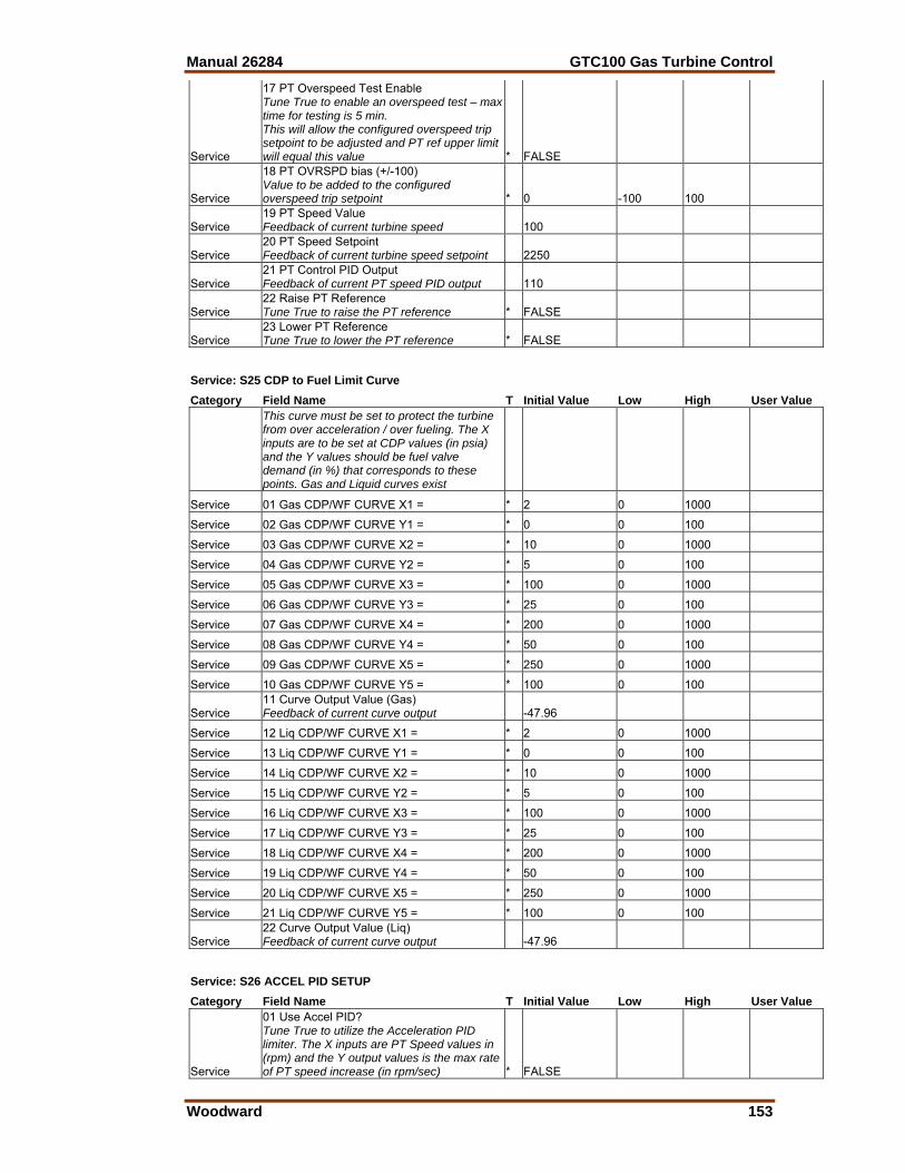
Manual 26284 GTC100 Gas Turbine Control
Woodward 153
Service
17 PT Overspeed Test Enable Tune True to enable an overspeed test – max time for testing is 5 min. This will allow the configured overspeed trip setpoint to be adjusted and PT ref upper limit will equal this value * FALSE
Service
18 PT OVRSPD bias (+/-100) Value to be added to the configured overspeed trip setpoint * 0 -100 100
Service 19 PT Speed Value Feedback of current turbine speed 100
Service 20 PT Speed Setpoint Feedback of current turbine speed setpoint 2250
Service 21 PT Control PID Output Feedback of current PT speed PID output 110
Service 22 Raise PT Reference Tune True to raise the PT reference * FALSE
Service 23 Lower PT Reference Tune True to lower the PT reference * FALSE
Service: S25 CDP to Fuel Limit Curve Category Field Name T Initial Value Low High User Value
This curve must be set to protect the turbine from over acceleration / over fueling. The X inputs are to be set at CDP values (in psia) and the Y values should be fuel valve demand (in %) that corresponds to these points. Gas and Liquid curves exist
Service 01 Gas CDP/WF CURVE X1 = * 2 0 1000
Service 02 Gas CDP/WF CURVE Y1 = * 0 0 100
Service 03 Gas CDP/WF CURVE X2 = * 10 0 1000
Service 04 Gas CDP/WF CURVE Y2 = * 5 0 100
Service 05 Gas CDP/WF CURVE X3 = * 100 0 1000
Service 06 Gas CDP/WF CURVE Y3 = * 25 0 100
Service 07 Gas CDP/WF CURVE X4 = * 200 0 1000
Service 08 Gas CDP/WF CURVE Y4 = * 50 0 100
Service 09 Gas CDP/WF CURVE X5 = * 250 0 1000
Service 10 Gas CDP/WF CURVE Y5 = * 100 0 100
Service 11 Curve Output Value (Gas) Feedback of current curve output -47.96
Service 12 Liq CDP/WF CURVE X1 = * 2 0 1000
Service 13 Liq CDP/WF CURVE Y1 = * 0 0 100
Service 14 Liq CDP/WF CURVE X2 = * 10 0 1000
Service 15 Liq CDP/WF CURVE Y2 = * 5 0 100
Service 16 Liq CDP/WF CURVE X3 = * 100 0 1000
Service 17 Liq CDP/WF CURVE Y3 = * 25 0 100
Service 18 Liq CDP/WF CURVE X4 = * 200 0 1000
Service 19 Liq CDP/WF CURVE Y4 = * 50 0 100
Service 20 Liq CDP/WF CURVE X5 = * 250 0 1000
Service 21 Liq CDP/WF CURVE Y5 = * 100 0 100
Service 22 Curve Output Value (Liq) Feedback of current curve output -47.96
Service: S26 ACCEL PID SETUP Category Field Name T Initial Value Low High User Value
Service
01 Use Accel PID? Tune True to utilize the Acceleration PID limiter. The X inputs are PT Speed values in (rpm) and the Y output values is the max rate of PT speed increase (in rpm/sec) * FALSE

GTC100 Gas Turbine Control Manual 26284
154 Woodward
Service 02 Confirm Choice FALSE
Service 03 Accel PID Prop Gain * 0.004 0.001 1
Service 04 Accel PID Integral Gain * 20 0.100 50
Service 05 Accel Ref Curv X1 = * 0 0 500
Service 06 Accel Ref Curv Y1 = * 75 10 2000
Service 07 Accel Ref Curv X2 = * 3000 1000 20000
Service 08 Accel Ref Curv Y2 = * 75 10 2000
Service 09 Accel Ref Curv X3 = * 3200 1000 20000
Service 10 Accel Ref Curv Y3 = * 500 10 2000
Service 11 Accel Ref Curv X4 = * 3600 1000 20000
Service 12 Accel Ref Curv Y4 = 500 100 2000
Service 13 Accel Ref Curv X5 = * 3650 1000 20000
Service 14 Accel Ref Curv Y5 = * 750 100 2000
Service 15 Accel Ref Curv X6 = * 3650 1000 20000
Service 16 Accel Ref Curv Y6 = * 750 100 2000
Service 17 SPD ACCEL Value 0
Service 18 SPD ACCEL Setpoint 75
Service 19 ACCEL Control PID Output -47.975
Service 20 ACCEL Prop Gain Sub-Idle * 0.044 0.001 1
Service: S27 DECEL Curve (CDP) SETUP Category Field Name T Initial Value Low High User Value
Service
01 Use Decel (CDP) Curve? Tune True to utilize the Deceleration curve limiter. The X inputs are CDP values in (psia) and the Y output values are the fuel valve % demand * TRUE
Service 02 Gas DECEL CURVE X1 = * 0 0 1000
Service 03 Gas DECEL CURVE Y1 = * 0 0 100
Service 04 Gas DECEL CURVE X2 = * 35 0 1000
Service 05 Gas DECEL CURVE Y2 = * 0 0 100
Service 06 Gas DECEL CURVE X3 = * 75 0 1000
Service 07 Gas DECEL CURVE Y3 = * 5 0 100
Service 08 Gas DECEL CURVE X4 = * 250 0 1000
Service 09 Gas DECEL CURVE Y4 = * 5 0 100
Service 10 Gas DECEL CURVE X5 = * 300 0 1000
Service 11 Gas DECEL CURVE Y5 = * 5 0 100
Service 12 Curve Output Value (Gas) 0
Service 13 Liq DECEL CURVE X1 = * 0 0 1000
Service 14 Liq DECEL CURVE Y1 = * 0 0 100
Service 15 Liq DECEL CURVE X2 = * 35 0 1000
Service 16 Liq DECEL CURVE Y2 = * 0 0 100
Service 17 Liq DECEL CURVE X3 = * 75 0 1000
Service 18 Liq DECEL CURVE Y3 = * 5 0 100
Service 19 Liq DECEL CURVE X4 = * 250 0 1000
Service 20 Liq DECEL CURVE Y4 = * 5 0 100
Service 21 Liq DECEL CURVE X5 = * 300 0 1000
Service 22 Liq DECEL CURVE Y5 = * 5 0 100
Service 23 Curve Output Value (Liq) 0
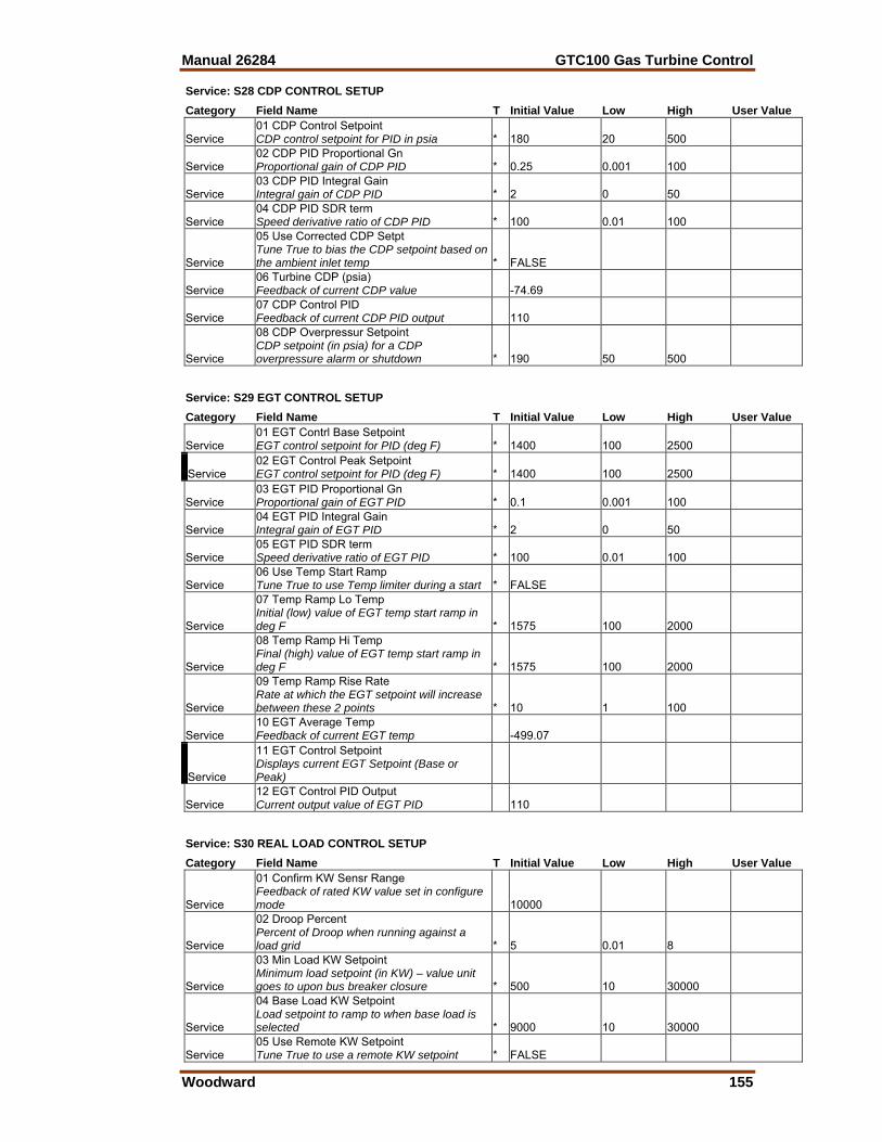
Manual 26284 GTC100 Gas Turbine Control
Woodward 155
Service: S28 CDP CONTROL SETUP Category Field Name T Initial Value Low High User Value
Service 01 CDP Control Setpoint CDP control setpoint for PID in psia * 180 20 500
Service 02 CDP PID Proportional Gn Proportional gain of CDP PID * 0.25 0.001 100
Service 03 CDP PID Integral Gain Integral gain of CDP PID * 2 0 50
Service 04 CDP PID SDR term Speed derivative ratio of CDP PID * 100 0.01 100
Service
05 Use Corrected CDP Setpt Tune True to bias the CDP setpoint based on the ambient inlet temp * FALSE
Service 06 Turbine CDP (psia) Feedback of current CDP value -74.69
Service 07 CDP Control PID Feedback of current CDP PID output 110
Service
08 CDP Overpressur Setpoint CDP setpoint (in psia) for a CDP overpressure alarm or shutdown * 190 50 500
Service: S29 EGT CONTROL SETUP Category Field Name T Initial Value Low High User Value
Service 01 EGT Contrl Base Setpoint EGT control setpoint for PID (deg F) * 1400 100 2500
Service 02 EGT Control Peak Setpoint EGT control setpoint for PID (deg F) * 1400 100 2500
Service 03 EGT PID Proportional Gn Proportional gain of EGT PID * 0.1 0.001 100
Service 04 EGT PID Integral Gain Integral gain of EGT PID * 2 0 50
Service 05 EGT PID SDR term Speed derivative ratio of EGT PID * 100 0.01 100
Service 06 Use Temp Start Ramp Tune True to use Temp limiter during a start * FALSE
Service
07 Temp Ramp Lo Temp Initial (low) value of EGT temp start ramp in deg F * 1575 100 2000
Service
08 Temp Ramp Hi Temp Final (high) value of EGT temp start ramp in deg F * 1575 100 2000
Service
09 Temp Ramp Rise Rate Rate at which the EGT setpoint will increase between these 2 points * 10 1 100
Service 10 EGT Average Temp Feedback of current EGT temp -499.07
Service
11 EGT Control Setpoint Displays current EGT Setpoint (Base or Peak)
Service 12 EGT Control PID Output Current output value of EGT PID 110
Service: S30 REAL LOAD CONTROL SETUP Category Field Name T Initial Value Low High User Value
Service
01 Confirm KW Sensr Range Feedback of rated KW value set in configure mode 10000
Service
02 Droop Percent Percent of Droop when running against a load grid * 5 0.01 8
Service
03 Min Load KW Setpoint Minimum load setpoint (in KW) – value unit goes to upon bus breaker closure * 500 10 30000
Service
04 Base Load KW Setpoint Load setpoint to ramp to when base load is selected * 9000 10 30000
Service 05 Use Remote KW Setpoint Tune True to use a remote KW setpoint * FALSE
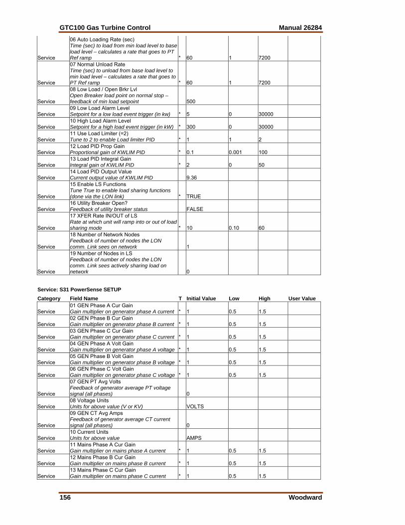
GTC100 Gas Turbine Control Manual 26284
156 Woodward
Service
06 Auto Loading Rate (sec) Time (sec) to load from min load level to base load level – calculates a rate that goes to PT Ref ramp * 60 1 7200
Service
07 Normal Unload Rate Time (sec) to unload from base load level to min load level – calculates a rate that goes to PT Ref ramp * 60 1 7200
Service
08 Low Load / Open Brkr Lvl Open Breaker load point on normal stop – feedback of min load setpoint 500
Service 09 Low Load Alarm Level Setpoint for a low load event trigger (in kw) * 5 0 30000
Service 10 High Load Alarm Level Setpoint for a high load event trigger (in kW) * 300 0 30000
Service 11 Use Load Limiter (=2) Tune to 2 to enable Load limiter PID * 1 1 2
Service 12 Load PID Prop Gain Proportional gain of KWLIM PID * 0.1 0.001 100
Service 13 Load PID Integral Gain Integral gain of KWLIM PID * 2 0 50
Service 14 Load PID Output Value Current output value of KWLIM PID 9.36
Service
15 Enable LS Functions Tune True to enable load sharing functions (done via the LON link) * TRUE
Service 16 Utility Breaker Open? Feedback of utility breaker status FALSE
Service
17 XFER Rate IN/OUT of LS Rate at which unit will ramp into or out of load sharing mode * 10 0.10 60
Service
18 Number of Network Nodes Feedback of number of nodes the LON comm. Link sees on network 1
Service
19 Number of Nodes in LS Feedback of number of nodes the LON comm. Link sees actively sharing load on network 0
Service: S31 PowerSense SETUP Category Field Name T Initial Value Low High User Value
Service 01 GEN Phase A Cur Gain Gain multiplier on generator phase A current * 1 0.5 1.5
Service 02 GEN Phase B Cur Gain Gain multiplier on generator phase B current * 1 0.5 1.5
Service 03 GEN Phase C Cur Gain Gain multiplier on generator phase C current * 1 0.5 1.5
Service 04 GEN Phase A Volt Gain Gain multiplier on generator phase A voltage * 1 0.5 1.5
Service 05 GEN Phase B Volt Gain Gain multiplier on generator phase B voltage * 1 0.5 1.5
Service 06 GEN Phase C Volt Gain Gain multiplier on generator phase C voltage * 1 0.5 1.5
Service
07 GEN PT Avg Volts Feedback of generator average PT voltage signal (all phases) 0
Service 08 Voltage Units Units for above value (V or KV) VOLTS
Service
09 GEN CT Avg Amps Feedback of generator average CT current signal (all phases) 0
Service 10 Current Units Units for above value AMPS
Service 11 Mains Phase A Cur Gain Gain multiplier on mains phase A current * 1 0.5 1.5
Service 12 Mains Phase B Cur Gain Gain multiplier on mains phase B current * 1 0.5 1.5
Service 13 Mains Phase C Cur Gain Gain multiplier on mains phase C current * 1 0.5 1.5
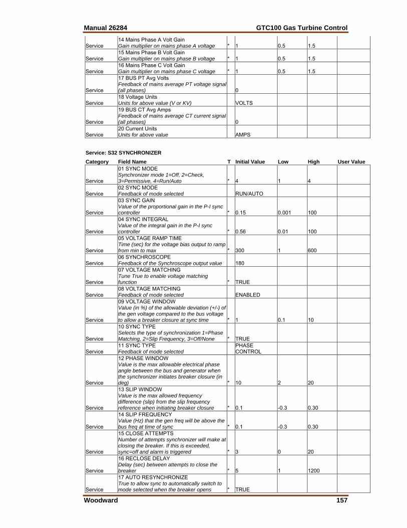
Manual 26284 GTC100 Gas Turbine Control
Woodward 157
Service 14 Mains Phase A Volt Gain Gain multiplier on mains phase A voltage * 1 0.5 1.5
Service 15 Mains Phase B Volt Gain Gain multiplier on mains phase B voltage * 1 0.5 1.5
Service 16 Mains Phase C Volt Gain Gain multiplier on mains phase C voltage * 1 0.5 1.5
Service
17 BUS PT Avg Volts Feedback of mains average PT voltage signal (all phases) 0
Service 18 Voltage Units Units for above value (V or KV) VOLTS
Service
19 BUS CT Avg Amps Feedback of mains average CT current signal (all phases) 0
Service 20 Current Units Units for above value AMPS
Service: S32 SYNCHRONIZER Category Field Name T Initial Value Low High User Value
Service
01 SYNC MODE Synchronizer mode 1=Off, 2=Check, 3=Permissive, 4=Run/Auto * 4 1 4
Service 02 SYNC MODE Feedback of mode selected RUN/AUTO
Service
03 SYNC GAIN Value of the proportional gain in the P-I sync controller * 0.15 0.001 100
Service
04 SYNC INTEGRAL Value of the integral gain in the P-I sync controller * 0.56 0.01 100
Service
05 VOLTAGE RAMP TIME Time (sec) for the voltage bias output to ramp from min to max * 300 1 600
Service 06 SYNCHROSCOPE Feedback of the Synchroscope output value 180
Service
07 VOLTAGE MATCHING Tune True to enable voltage matching function * TRUE
Service 08 VOLTAGE MATCHING Feedback of mode selected ENABLED
Service
09 VOLTAGE WINDOW Value (in %) of the allowable deviation (+/-) of the gen voltage compared to the bus voltage to allow a breaker closure at sync time * 1 0.1 10
Service
10 SYNC TYPE Selects the type of synchronization 1=Phase Matching, 2=Slip Frequency, 3=Off/None * TRUE
Service 11 SYNC TYPE Feedback of mode selected
PHASE CONTROL
Service
12 PHASE WINDOW Value is the max allowable electrical phase angle between the bus and generator when the synchronizer initiates breaker closure (in deg) * 10 2 20
Service
13 SLIP WINDOW Value is the max allowed frequency difference (slip) from the slip frequency reference when initiating breaker closure * 0.1 -0.3 0.30
Service
14 SLIP FREQUENCY Value (Hz) that the gen freq will be above the bus freq at time of sync * 0.1 -0.3 0.30
Service
15 CLOSE ATTEMPTS Number of attempts synchronizer will make at closing the breaker. If this is exceeded, sync=off and alarm is triggered * 3 0 20
Service
16 RECLOSE DELAY Delay (sec) between attempts to close the breaker * 5 1 1200
Service
17 AUTO RESYNCHRONIZE True to allow sync to automatically switch to mode selected when the breaker opens * TRUE
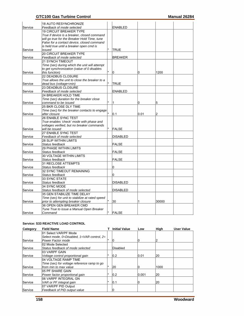
GTC100 Gas Turbine Control Manual 26284
158 Woodward
Service 18 AUTO RESYNCHRONIZE Feedback of mode selected ENABLED
Service
19 CIRCUIT BREAKER TYPE True if device is a breaker, closed command will go true for the Breaker Hold Time, tune False for a contact device, closed command is held true until a breaker open cmd is issued * TRUE
Service 20 CIRCUIT BREAKER TYPE Feedback of mode selected BREAKER
Service
21 SYNCH TIMEOUT Time (sec) during which the unit will attempt to get synchronization (value of 0 disables this function) * 0 0 1200
Service
22 DEADBUS CLOSURE True allows the unit to close the breaker to a dead bus (voltage<min) * TRUE
Service 23 DEADBUS CLOSURE Feedback of mode selected ENABLED
Service
24 BREAKER HOLD TIME Time (sec) duration for the breaker close command to be issued * 1 0 5
Service
25 BKR CLOSE DLY TIME Time (sec) for the breaker contacts to engage after closure * 0.1 0.01 2
Service
26 ENABLE SYNC TEST True enables ‘check’ mode with phase and voltages verified, but no breaker commands will be issued * FALSE
Service 27 ENABLE SYNC TEST Feedback of mode selected DISABLED
Service 28 SLIP WITHIN LIMITS Status feedback FALSE
Service 29 PHASE WITHIN LIMITS Status feedback FALSE
Service 30 VOLTAGE WITHIN LIMITS Status feedback FALSE
Service 31 RECLOSE ATTEMPTS Status feedback 0
Service 32 SYNC TIMEOUT REMAINING Status feedback 0
Service 33 SYNC STATE Status feedback DISABLED
Service 34 SYNC MODE Status feedback of mode selected DISABLED
Service
35 GEN STABILIZE TIME DELAY Time (sec) for unit to stabilize at rated speed prior to attempting breaker closure * 30 1 30000
Service
36 OPEN GEN BREAKER CMD Tune True to issue a Manual Open Breaker Command * FALSE
Service: S33 REACTIVE LOAD CONTROL Category Field Name T Initial Value Low High User Value
Service
01 Select VAR/PF Mode Select mode, 0=Disabled, 1=VAR control, 2= Power Factor mode * 0 0 2
Service 02 Mode Selected Status feedback of mode selected Disabled
Service 03 VARPF GAIN Voltage control proportional gain * 0.2 0.01 20
Service
04 VOLTAGE RAMP TIME Time (sec) for voltage reference ramp to go from min to max value * 20 0 1000
Service 05 PF SHARE GAIN Power factor proportional gain * 0.2 0.001 20
Service 06 VARPF INTEGRAL GN VAR or PF integral gain * 0.1 0 20
Service 07 VAR/PF PID Output Feedback of PID output value 0
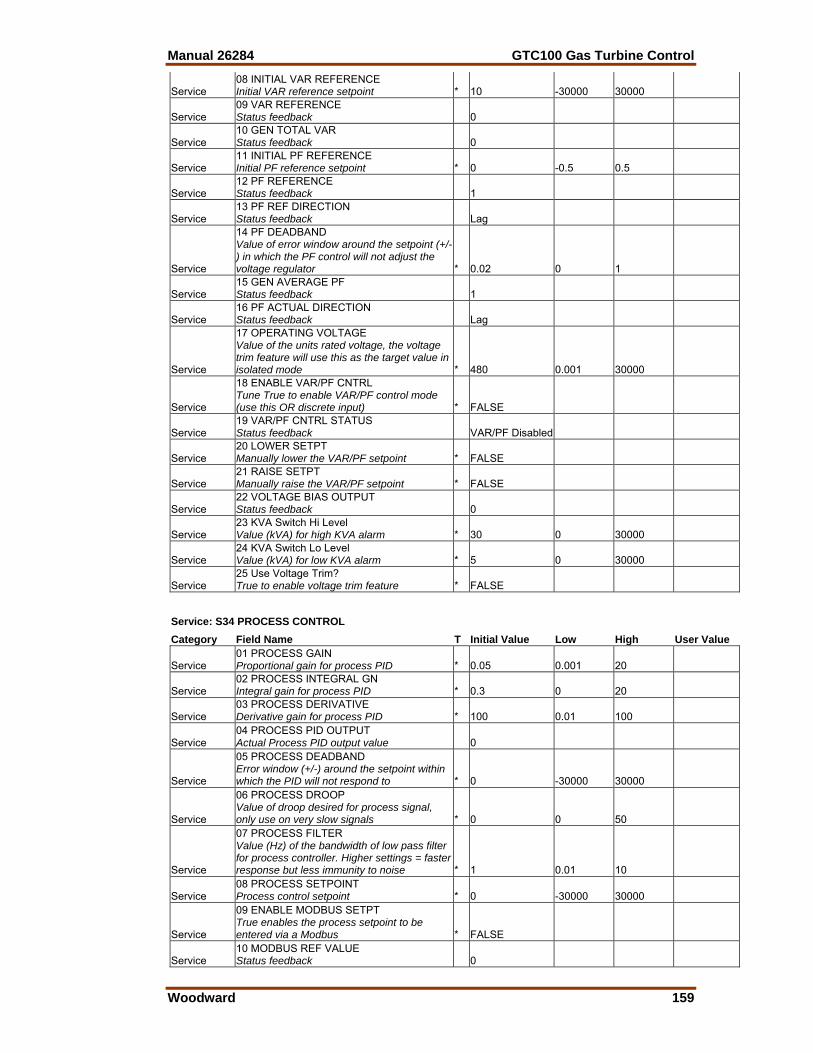
Manual 26284 GTC100 Gas Turbine Control
Woodward 159
Service 08 INITIAL VAR REFERENCE Initial VAR reference setpoint * 10 -30000 30000
Service 09 VAR REFERENCE Status feedback 0
Service 10 GEN TOTAL VAR Status feedback 0
Service 11 INITIAL PF REFERENCE Initial PF reference setpoint * 0 -0.5 0.5
Service 12 PF REFERENCE Status feedback 1
Service 13 PF REF DIRECTION Status feedback Lag
Service
14 PF DEADBAND Value of error window around the setpoint (+/-) in which the PF control will not adjust the voltage regulator * 0.02 0 1
Service 15 GEN AVERAGE PF Status feedback 1
Service 16 PF ACTUAL DIRECTION Status feedback Lag
Service
17 OPERATING VOLTAGE Value of the units rated voltage, the voltage trim feature will use this as the target value in isolated mode * 480 0.001 30000
Service
18 ENABLE VAR/PF CNTRL Tune True to enable VAR/PF control mode (use this OR discrete input) * FALSE
Service 19 VAR/PF CNTRL STATUS Status feedback VAR/PF Disabled
Service 20 LOWER SETPT Manually lower the VAR/PF setpoint * FALSE
Service 21 RAISE SETPT Manually raise the VAR/PF setpoint * FALSE
Service 22 VOLTAGE BIAS OUTPUT Status feedback 0
Service 23 KVA Switch Hi Level Value (kVA) for high KVA alarm * 30 0 30000
Service 24 KVA Switch Lo Level Value (kVA) for low KVA alarm * 5 0 30000
Service 25 Use Voltage Trim? True to enable voltage trim feature * FALSE
Service: S34 PROCESS CONTROL Category Field Name T Initial Value Low High User Value
Service 01 PROCESS GAIN Proportional gain for process PID * 0.05 0.001 20
Service 02 PROCESS INTEGRAL GN Integral gain for process PID * 0.3 0 20
Service 03 PROCESS DERIVATIVE Derivative gain for process PID * 100 0.01 100
Service 04 PROCESS PID OUTPUT Actual Process PID output value 0
Service
05 PROCESS DEADBAND Error window (+/-) around the setpoint within which the PID will not respond to * 0 -30000 30000
Service
06 PROCESS DROOP Value of droop desired for process signal, only use on very slow signals * 0 0 50
Service
07 PROCESS FILTER Value (Hz) of the bandwidth of low pass filter for process controller. Higher settings = faster response but less immunity to noise * 1 0.01 10
Service 08 PROCESS SETPOINT Process control setpoint * 0 -30000 30000
Service
09 ENABLE MODBUS SETPT True enables the process setpoint to be entered via a Modbus * FALSE
Service 10 MODBUS REF VALUE Status feedback 0
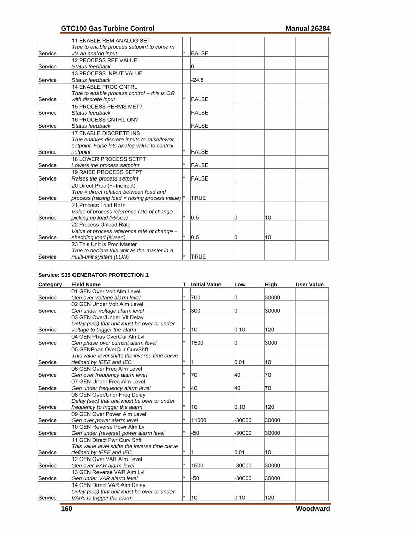
GTC100 Gas Turbine Control Manual 26284
160 Woodward
Service
11 ENABLE REM ANALOG SET True to enable process setpoint to come in via an analog input * FALSE
Service 12 PROCESS REF VALUE Status feedback 0
Service 13 PROCESS INPUT VALUE Status feedback -24.8
Service
14 ENABLE PROC CNTRL True to enable process control – this is OR with discrete input * FALSE
Service 15 PROCESS PERMS MET? Status feedback FALSE
Service 16 PROCESS CNTRL ON? Status feedback FALSE
Service
17 ENABLE DISCRETE INS True enables discrete inputs to raise/lower setpoint, False lets analog value to control setpoint * FALSE
Service 18 LOWER PROCESS SETPT Lowers the process setpoint * FALSE
Service 19 RAISE PROCESS SETPT Raises the process setpoint * FALSE
Service
20 Direct Proc (F=Indirect) True = direct relation between load and process (raising load = raising process value) * TRUE
Service
21 Process Load Rate Value of process reference rate of change – picking up load (%/sec) * 0.5 0 10
Service
22 Process Unload Rate Value of process reference rate of change – shedding load (%/sec) * 0.5 0 10
Service
23 This Unit is Proc Master True to declare this unit as the master in a multi-unit system (LON) * TRUE
Service: S35 GENERATOR PROTECTION 1 Category Field Name T Initial Value Low High User Value
Service 01 GEN Over Volt Alm Level Gen over voltage alarm level * 700 0 30000
Service 02 GEN Under Volt Alm Level Gen under voltage alarm level * 300 0 30000
Service
03 GEN Over/Under Vlt Delay Delay (sec) that unit must be over or under voltage to trigger the alarm * 10 0.10 120
Service 04 GEN Phas OverCur AlmLvl Gen phase over current alarm level * 1500 0 3000
Service
05 GENPhas OverCur CurvShft This value level shifts the inverse time curve defined by IEEE and IEC * 1 0.01 10
Service 06 GEN Over Freq Alm Level Gen over frequency alarm level * 70 40 70
Service 07 GEN Under Freq Alm Level Gen under frequency alarm level * 40 40 70
Service
08 GEN Over/Undr Freq Delay Delay (sec) that unit must be over or under frequency to trigger the alarm * 10 0.10 120
Service 09 GEN Over Power Alm Level Gen over power alarm level * 11000 -30000 30000
Service 10 GEN Reverse Powr Alm Lvl Gen under (reverse) power alarm level * -50 -30000 30000
Service
11 GEN Direct Pwr Curv Shft This value level shifts the inverse time curve defined by IEEE and IEC * 1 0.01 10
Service 12 GEN Over VAR Alm Level Gen over VAR alarm level * 1500 -30000 30000
Service 13 GEN Reverse VAR Alm Lvl Gen under VAR alarm level * -50 -30000 30000
Service
14 GEN Direct VAR Alm Delay Delay (sec) that unit must be over or under VARs to trigger the alarm * 10 0.10 120
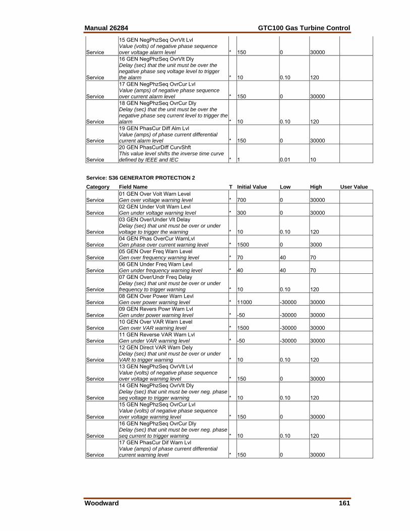
Manual 26284 GTC100 Gas Turbine Control
Woodward 161
Service
15 GEN NegPhzSeq OvrVlt Lvl Value (volts) of negative phase sequence over voltage alarm level * 150 0 30000
Service
16 GEN NegPhzSeq OvrVlt Dly Delay (sec) that the unit must be over the negative phase seq voltage level to trigger the alarm * 10 0.10 120
Service
17 GEN NegPhzSeq OvrCur Lvl Value (amps) of negative phase sequence over current alarm level * 150 0 30000
Service
18 GEN NegPhzSeq OvrCur Dly Delay (sec) that the unit must be over the negative phase seq current level to trigger the alarm * 10 0.10 120
Service
19 GEN PhasCur Diff Alm Lvl Value (amps) of phase current differential current alarm level * 150 0 30000
Service
20 GEN PhasCurDiff CurvShft This value level shifts the inverse time curve defined by IEEE and IEC * 1 0.01 10
Service: S36 GENERATOR PROTECTION 2 Category Field Name T Initial Value Low High User Value
Service 01 GEN Over Volt Warn Level Gen over voltage warning level * 700 0 30000
Service 02 GEN Under Volt Warn Levl Gen under voltage warning level * 300 0 30000
Service
03 GEN Over/Under Vlt Delay Delay (sec) that unit must be over or under voltage to trigger the warning * 10 0.10 120
Service 04 GEN Phas OverCur WarnLvl Gen phase over current warning level * 1500 0 3000
Service 05 GEN Over Freq Warn Level Gen over frequency warning level * 70 40 70
Service 06 GEN Under Freq Warn Levl Gen under frequency warning level * 40 40 70
Service
07 GEN Over/Undr Freq Delay Delay (sec) that unit must be over or under frequency to trigger warning * 10 0.10 120
Service 08 GEN Over Power Warn Levl Gen over power warning level * 11000 -30000 30000
Service 09 GEN Revers Powr Warn Lvl Gen under power warning level * -50 -30000 30000
Service 10 GEN Over VAR Warn Level Gen over VAR warning level * 1500 -30000 30000
Service 11 GEN Reverse VAR Warn Lvl Gen under VAR warning level * -50 -30000 30000
Service
12 GEN Direct VAR Warn Dely Delay (sec) that unit must be over or under VAR to trigger warning * 10 0.10 120
Service
13 GEN NegPhzSeq OvrVlt Lvl Value (volts) of negative phase sequence over voltage warning level * 150 0 30000
Service
14 GEN NegPhzSeq OvrVlt Dly Delay (sec) that unit must be over neg. phase seq voltage to trigger warning * 10 0.10 120
Service
15 GEN NegPhzSeq OvrCur Lvl Value (volts) of negative phase sequence over voltage warning level * 150 0 30000
Service
16 GEN NegPhzSeq OvrCur Dly Delay (sec) that unit must be over neg. phase seq current to trigger warning * 10 0.10 120
Service
17 GEN PhasCur Dif Warn Lvl Value (amps) of phase current differential current warning level * 150 0 30000
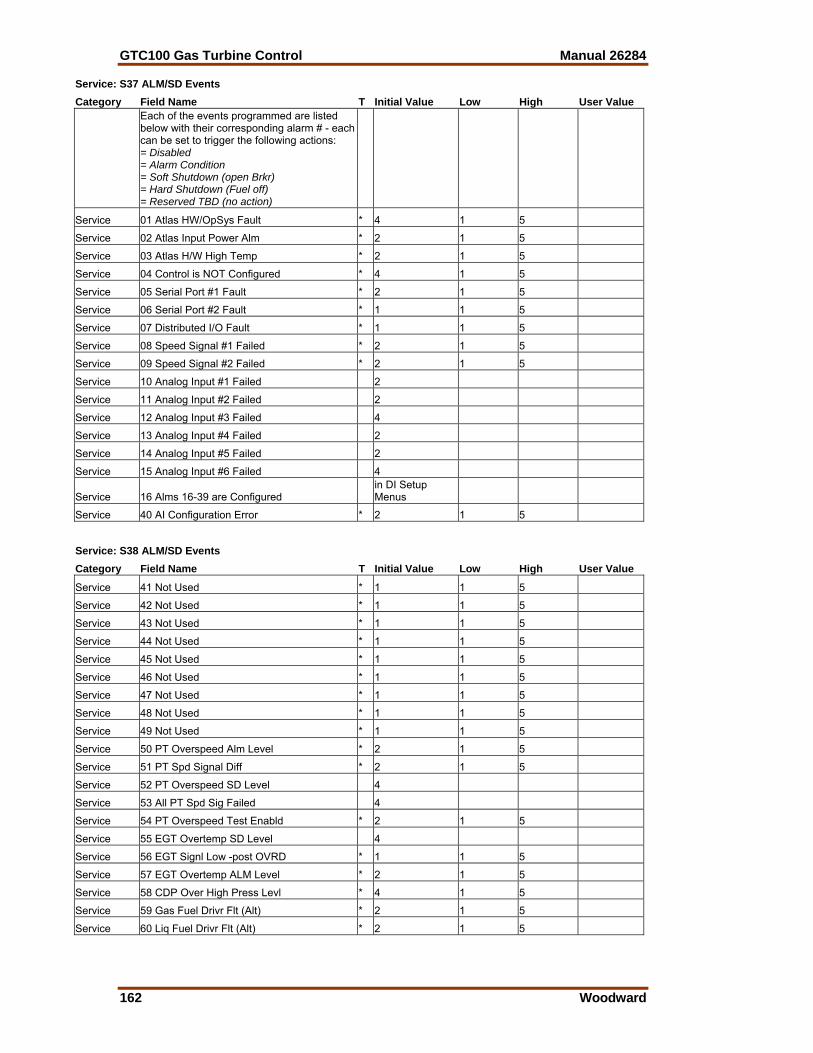
GTC100 Gas Turbine Control Manual 26284
162 Woodward
Service: S37 ALM/SD Events Category Field Name T Initial Value Low High User Value
Each of the events programmed are listed below with their corresponding alarm # - each can be set to trigger the following actions: = Disabled = Alarm Condition = Soft Shutdown (open Brkr) = Hard Shutdown (Fuel off) = Reserved TBD (no action)
Service 01 Atlas HW/OpSys Fault * 4 1 5
Service 02 Atlas Input Power Alm * 2 1 5
Service 03 Atlas H/W High Temp * 2 1 5
Service 04 Control is NOT Configured * 4 1 5
Service 05 Serial Port #1 Fault * 2 1 5
Service 06 Serial Port #2 Fault * 1 1 5
Service 07 Distributed I/O Fault * 1 1 5
Service 08 Speed Signal #1 Failed * 2 1 5
Service 09 Speed Signal #2 Failed * 2 1 5
Service 10 Analog Input #1 Failed 2
Service 11 Analog Input #2 Failed 2
Service 12 Analog Input #3 Failed 4
Service 13 Analog Input #4 Failed 2
Service 14 Analog Input #5 Failed 2
Service 15 Analog Input #6 Failed 4
Service 16 Alms 16-39 are Configured in DI Setup Menus
Service 40 AI Configuration Error * 2 1 5
Service: S38 ALM/SD Events Category Field Name T Initial Value Low High User Value
Service 41 Not Used * 1 1 5
Service 42 Not Used * 1 1 5
Service 43 Not Used * 1 1 5
Service 44 Not Used * 1 1 5
Service 45 Not Used * 1 1 5
Service 46 Not Used * 1 1 5
Service 47 Not Used * 1 1 5
Service 48 Not Used * 1 1 5
Service 49 Not Used * 1 1 5
Service 50 PT Overspeed Alm Level * 2 1 5
Service 51 PT Spd Signal Diff * 2 1 5
Service 52 PT Overspeed SD Level 4
Service 53 All PT Spd Sig Failed 4
Service 54 PT Overspeed Test Enabld * 2 1 5
Service 55 EGT Overtemp SD Level 4
Service 56 EGT Signl Low -post OVRD * 1 1 5
Service 57 EGT Overtemp ALM Level * 2 1 5
Service 58 CDP Over High Press Levl * 4 1 5
Service 59 Gas Fuel Drivr Flt (Alt) * 2 1 5
Service 60 Liq Fuel Drivr Flt (Alt) * 2 1 5
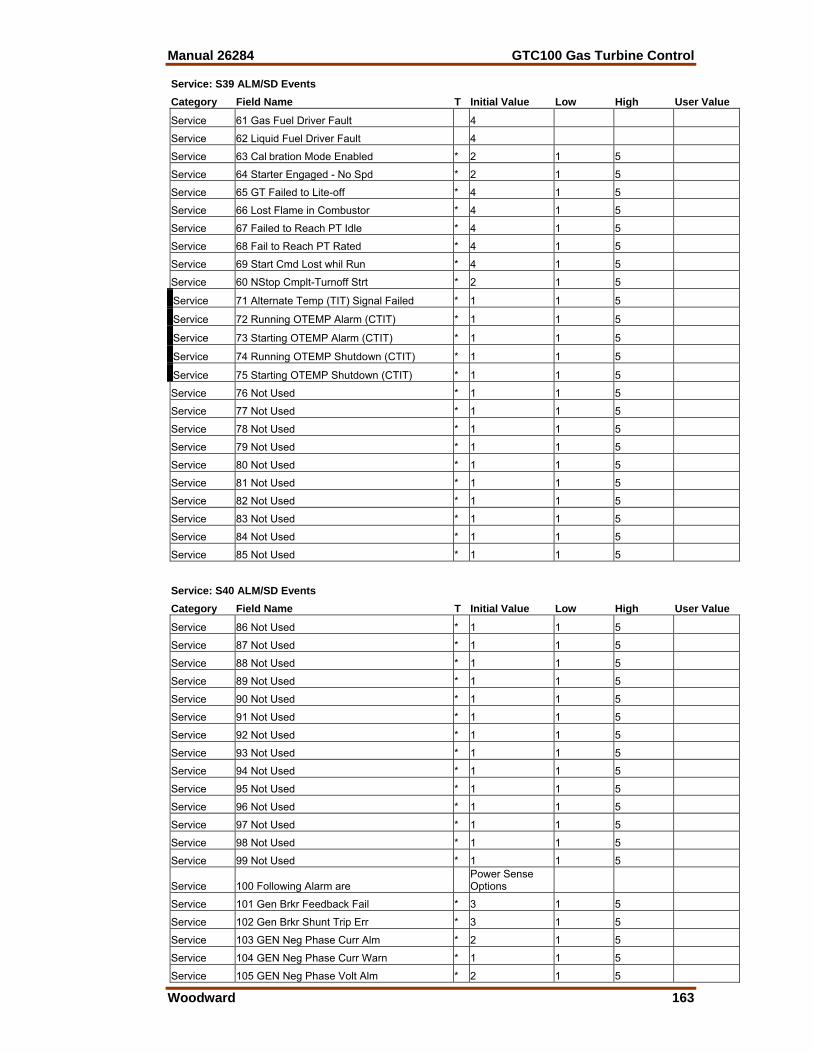
Manual 26284 GTC100 Gas Turbine Control
Woodward 163
Service: S39 ALM/SD Events Category Field Name T Initial Value Low High User Value
Service 61 Gas Fuel Driver Fault 4
Service 62 Liquid Fuel Driver Fault 4
Service 63 Cal bration Mode Enabled * 2 1 5
Service 64 Starter Engaged - No Spd * 2 1 5
Service 65 GT Failed to Lite-off * 4 1 5
Service 66 Lost Flame in Combustor * 4 1 5
Service 67 Failed to Reach PT Idle * 4 1 5
Service 68 Fail to Reach PT Rated * 4 1 5
Service 69 Start Cmd Lost whil Run * 4 1 5
Service 60 NStop Cmplt-Turnoff Strt * 2 1 5
Service 71 Alternate Temp (TIT) Signal Failed * 1 1 5
Service 72 Running OTEMP Alarm (CTIT) * 1 1 5
Service 73 Starting OTEMP Alarm (CTIT) * 1 1 5
Service 74 Running OTEMP Shutdown (CTIT) * 1 1 5
Service 75 Starting OTEMP Shutdown (CTIT) * 1 1 5
Service 76 Not Used * 1 1 5
Service 77 Not Used * 1 1 5
Service 78 Not Used * 1 1 5
Service 79 Not Used * 1 1 5
Service 80 Not Used * 1 1 5
Service 81 Not Used * 1 1 5
Service 82 Not Used * 1 1 5
Service 83 Not Used * 1 1 5
Service 84 Not Used * 1 1 5
Service 85 Not Used * 1 1 5
Service: S40 ALM/SD Events Category Field Name T Initial Value Low High User Value
Service 86 Not Used * 1 1 5
Service 87 Not Used * 1 1 5
Service 88 Not Used * 1 1 5
Service 89 Not Used * 1 1 5
Service 90 Not Used * 1 1 5
Service 91 Not Used * 1 1 5
Service 92 Not Used * 1 1 5
Service 93 Not Used * 1 1 5
Service 94 Not Used * 1 1 5
Service 95 Not Used * 1 1 5
Service 96 Not Used * 1 1 5
Service 97 Not Used * 1 1 5
Service 98 Not Used * 1 1 5
Service 99 Not Used * 1 1 5
Service 100 Following Alarm are Power Sense Options
Service 101 Gen Brkr Feedback Fail * 3 1 5
Service 102 Gen Brkr Shunt Trip Err * 3 1 5
Service 103 GEN Neg Phase Curr Alm * 2 1 5
Service 104 GEN Neg Phase Curr Warn * 1 1 5
Service 105 GEN Neg Phase Volt Alm * 2 1 5
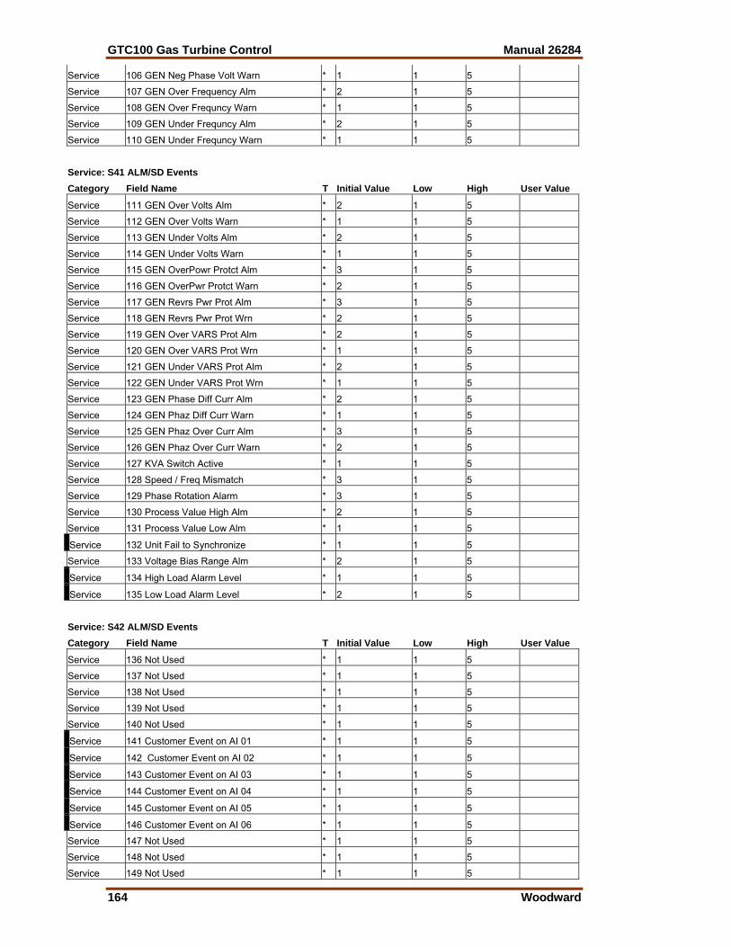
GTC100 Gas Turbine Control Manual 26284
164 Woodward
Service 106 GEN Neg Phase Volt Warn * 1 1 5
Service 107 GEN Over Frequency Alm * 2 1 5
Service 108 GEN Over Frequncy Warn * 1 1 5
Service 109 GEN Under Frequncy Alm * 2 1 5
Service 110 GEN Under Frequncy Warn * 1 1 5
Service: S41 ALM/SD Events Category Field Name T Initial Value Low High User Value
Service 111 GEN Over Volts Alm * 2 1 5
Service 112 GEN Over Volts Warn * 1 1 5
Service 113 GEN Under Volts Alm * 2 1 5
Service 114 GEN Under Volts Warn * 1 1 5
Service 115 GEN OverPowr Protct Alm * 3 1 5
Service 116 GEN OverPwr Protct Warn * 2 1 5
Service 117 GEN Revrs Pwr Prot Alm * 3 1 5
Service 118 GEN Revrs Pwr Prot Wrn * 2 1 5
Service 119 GEN Over VARS Prot Alm * 2 1 5
Service 120 GEN Over VARS Prot Wrn * 1 1 5
Service 121 GEN Under VARS Prot Alm * 2 1 5
Service 122 GEN Under VARS Prot Wrn * 1 1 5
Service 123 GEN Phase Diff Curr Alm * 2 1 5
Service 124 GEN Phaz Diff Curr Warn * 1 1 5
Service 125 GEN Phaz Over Curr Alm * 3 1 5
Service 126 GEN Phaz Over Curr Warn * 2 1 5
Service 127 KVA Switch Active * 1 1 5
Service 128 Speed / Freq Mismatch * 3 1 5
Service 129 Phase Rotation Alarm * 3 1 5
Service 130 Process Value High Alm * 2 1 5
Service 131 Process Value Low Alm * 1 1 5
Service 132 Unit Fail to Synchronize * 1 1 5
Service 133 Voltage Bias Range Alm * 2 1 5
Service 134 High Load Alarm Level * 1 1 5
Service 135 Low Load Alarm Level * 2 1 5
Service: S42 ALM/SD Events Category Field Name T Initial Value Low High User Value
Service 136 Not Used * 1 1 5
Service 137 Not Used * 1 1 5
Service 138 Not Used * 1 1 5
Service 139 Not Used * 1 1 5
Service 140 Not Used * 1 1 5
Service 141 Customer Event on AI 01 * 1 1 5
Service 142 Customer Event on AI 02 * 1 1 5
Service 143 Customer Event on AI 03 * 1 1 5
Service 144 Customer Event on AI 04 * 1 1 5
Service 145 Customer Event on AI 05 * 1 1 5
Service 146 Customer Event on AI 06 * 1 1 5
Service 147 Not Used * 1 1 5
Service 148 Not Used * 1 1 5
Service 149 Not Used * 1 1 5
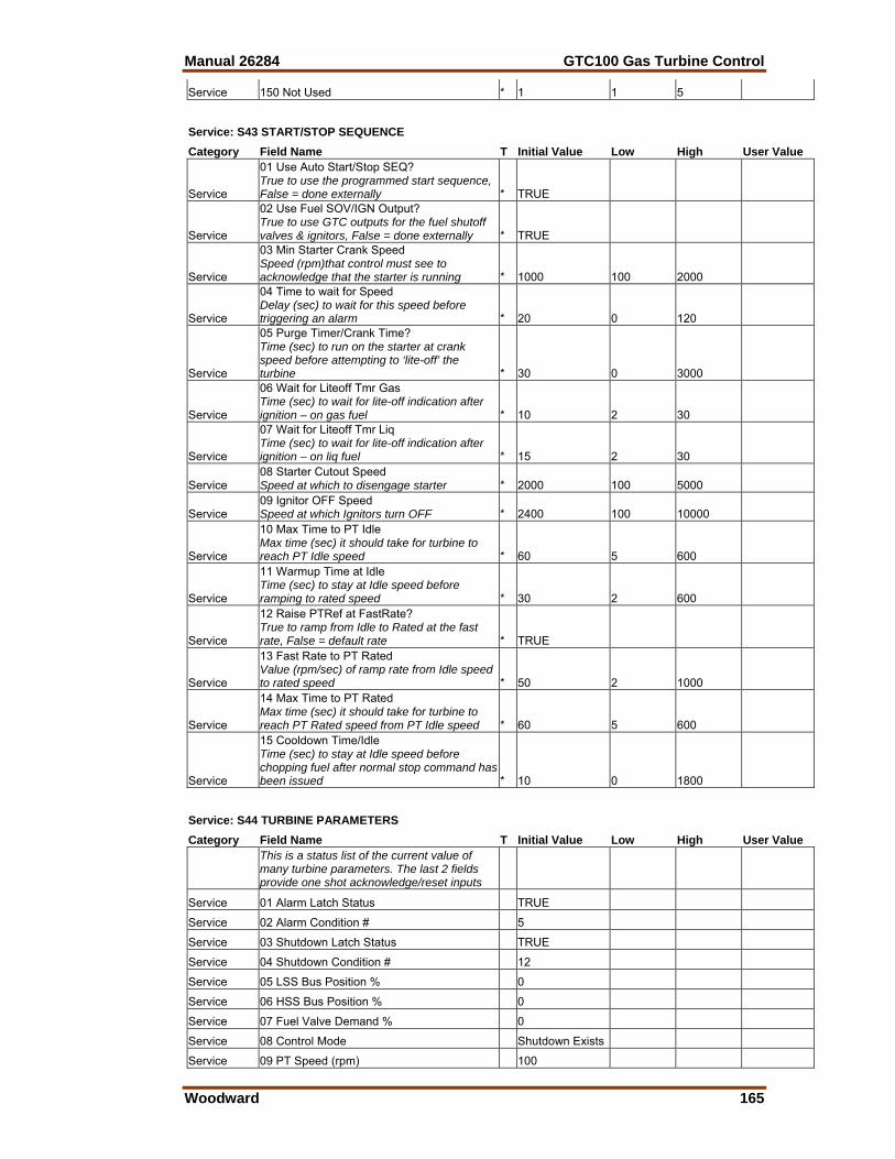
Manual 26284 GTC100 Gas Turbine Control
Woodward 165
Service 150 Not Used * 1 1 5
Service: S43 START/STOP SEQUENCE Category Field Name T Initial Value Low High User Value
Service
01 Use Auto Start/Stop SEQ? True to use the programmed start sequence, False = done externally * TRUE
Service
02 Use Fuel SOV/IGN Output? True to use GTC outputs for the fuel shutoff valves & ignitors, False = done externally * TRUE
Service
03 Min Starter Crank Speed Speed (rpm)that control must see to acknowledge that the starter is running * 1000 100 2000
Service
04 Time to wait for Speed Delay (sec) to wait for this speed before triggering an alarm * 20 0 120
Service
05 Purge Timer/Crank Time? Time (sec) to run on the starter at crank speed before attempting to ‘lite-off’ the turbine * 30 0 3000
Service
06 Wait for Liteoff Tmr Gas Time (sec) to wait for lite-off indication after ignition – on gas fuel * 10 2 30
Service
07 Wait for Liteoff Tmr Liq Time (sec) to wait for lite-off indication after ignition – on liq fuel * 15 2 30
Service 08 Starter Cutout Speed Speed at which to disengage starter * 2000 100 5000
Service 09 Ignitor OFF Speed Speed at which Ignitors turn OFF * 2400 100 10000
Service
10 Max Time to PT Idle Max time (sec) it should take for turbine to reach PT Idle speed * 60 5 600
Service
11 Warmup Time at Idle Time (sec) to stay at Idle speed before ramping to rated speed * 30 2 600
Service
12 Raise PTRef at FastRate? True to ramp from Idle to Rated at the fast rate, False = default rate * TRUE
Service
13 Fast Rate to PT Rated Value (rpm/sec) of ramp rate from Idle speed to rated speed * 50 2 1000
Service
14 Max Time to PT Rated Max time (sec) it should take for turbine to reach PT Rated speed from PT Idle speed * 60 5 600
Service
15 Cooldown Time/Idle Time (sec) to stay at Idle speed before chopping fuel after normal stop command has been issued * 10 0 1800
Service: S44 TURBINE PARAMETERS Category Field Name T Initial Value Low High User Value
This is a status list of the current value of many turbine parameters. The last 2 fields provide one shot acknowledge/reset inputs
Service 01 Alarm Latch Status TRUE
Service 02 Alarm Condition # 5
Service 03 Shutdown Latch Status TRUE
Service 04 Shutdown Condition # 12
Service 05 LSS Bus Position % 0
Service 06 HSS Bus Position % 0
Service 07 Fuel Valve Demand % 0
Service 08 Control Mode Shutdown Exists
Service 09 PT Speed (rpm) 100
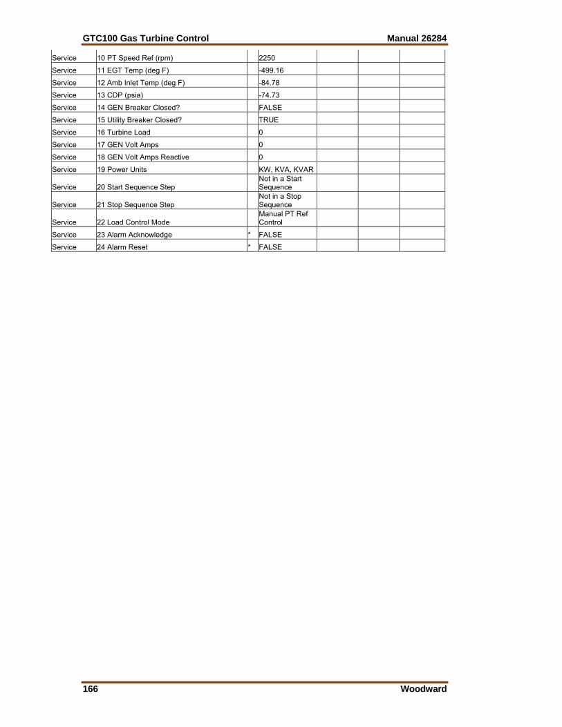
GTC100 Gas Turbine Control Manual 26284
166 Woodward
Service 10 PT Speed Ref (rpm) 2250
Service 11 EGT Temp (deg F) -499.16
Service 12 Amb Inlet Temp (deg F) -84.78
Service 13 CDP (psia) -74.73
Service 14 GEN Breaker Closed? FALSE
Service 15 Utility Breaker Closed? TRUE
Service 16 Turbine Load 0
Service 17 GEN Volt Amps 0
Service 18 GEN Volt Amps Reactive 0
Service 19 Power Units KW, KVA, KVAR
Service 20 Start Sequence Step Not in a Start Sequence
Service 21 Stop Sequence Step Not in a Stop Sequence
Service 22 Load Control Mode Manual PT Ref Control
Service 23 Alarm Acknowledge * FALSE
Service 24 Alarm Reset * FALSE

Manual 26284 GTC100 Gas Turbine Control
Woodward 167
Appendix E. Pre-Installation Control Information
Checklist Detail an I/O list (interfaces to GTC Fuel Control) • Analog Inputs & Outputs – (ranges, units, alarm & shutdown points) • Discrete Inputs – Active high or low • Relay outputs – NO or NC, contact load ratings • MPU Speed sensor specifications (# of teeth, gear ratio, hi/lo fail spds) • PowerSense module info PT/CT ratios, rated voltage, frequency • Fuel Actuator/Valve drivers – mA range (need SPC?), PPH flow vs. Valve
Pos. • Operator Interface – size, location, desired functionality • Communication Links to other devices – signal type, protocols • Termination wiring details (existing & upgrades) Control Limits • EGT topping temperature limit • CDP topping pressure limit • PT Speed – upper limit (Alm & SD), Ref limits (high & low) • Any Required Acceleration or Deceleration Schedules • Load Control functions utilized (or desired in the upgrade) Start-up Information • Electrical or Mechanical lite-off, valve degrees, start ramp percent • Fuel Info – Type, supply pressure, LHV, SG • Manifold pressure at lite-off • Fuel Flow information • Any EGT Start overtemp limit • Time from Lite-off to PT Idle Speed • Time from PT Idle to PT Rated speed Running Information • How do they typically operate the unit (Peak, Baseload, Process…) • Gathering the following info will greatly simplify GTC control configuration
Data Point CDP (psia) EGT (deg F) PT Speed Ref. Fuel Valve (%) Fuel Flow@ PT Idle @ PT Rated @ 10% Load @ 25% Load @ 50% Load @ 75% Load @ 100% Load

We appreciate your comments about the content of our publications.
Send comments to: [email protected]
Please reference publication 26284D.
PO Box 1519, Fort Collins CO 80522-1519, USA 1000 East Drake Road, Fort Collins CO 80525, USA Phone +1 (970) 482-5811 • Fax +1 (970) 498-3058
Email and Website—www.woodward.com
Woodward has company-owned plants, subsidiaries, and branches, as well as authorized distributors and other authorized service and sales facilities throughout the world.
Complete address / phone / fax / email information for all locations is available on our website.
2009/4/Fort Collins