this page intentionally left blank - hcfcd · 6.2 forebay design criteria and alternatives ... this...
TRANSCRIPT


This page intentionally left blank

Design Guidelines for HCFCD Wet Bottom Detention Basins with Water Quality Features
i HCFCD – April 2014
Table of Contents
Acronyms and Abbreviations ...................................................................................................................... iv Section 1.0 – Introduction ............................................................................................................................. 1
1.1 Background ........................................................................................................................................ 1 1.2 Basins Function as BMP .................................................................................................................... 1 1.3 Water Quality Program Goals ........................................................................................................... 1 1.4 Design Guidelines Context ................................................................................................................ 2 1.5 Purpose of Design Guidelines ........................................................................................................... 2 1.6 Design Guideline Organization ......................................................................................................... 3 1.7 Design Guideline Highlights ............................................................................................................. 4 1.8 Design Procedures ............................................................................................................................. 4
Section 2.0 – Regulatory Framework ........................................................................................................... 5 2.1 Overview ........................................................................................................................................... 5 2.2 MS4 Permit ........................................................................................................................................ 5 2.3 WQ Directives ................................................................................................................................... 5 2.4 HCFCD Mission ................................................................................................................................ 5 2.5 CWA §404 Exemptions ..................................................................................................................... 5 2.6 Required Environmental Permits ....................................................................................................... 6
Section 3.0 – Project Stages .......................................................................................................................... 7 3.1 Overview ........................................................................................................................................... 7 3.2 Work Breakdown Structure ............................................................................................................... 7
Section 4.0 – Project Planning ...................................................................................................................... 9 4.1 Overview ........................................................................................................................................... 9 4.2 Basics of Stormwater Treatment ..................................................................................................... 10 4.3 Water Quality Objectives ................................................................................................................ 12 4.4 Preliminary Project Siting and Sizing.............................................................................................. 14 4.5 Procedure – Project Planning........................................................................................................... 15
Section 5.0 – Project Development ............................................................................................................. 17 5.1 Overview ......................................................................................................................................... 17 5.2 Project Development Considerations .............................................................................................. 18 5.3 Watershed Inputs ............................................................................................................................. 19 5.4 Environmental Compliance ............................................................................................................. 20 5.5 Geotechnical Investigations ............................................................................................................. 22 5.6 Water Sources & Volumes .............................................................................................................. 23 5.6.1 Water Sources ............................................................................................................................... 26 5.6.1.1 Groundwater .............................................................................................................................. 26 5.6.1.2 Surface Water ............................................................................................................................ 27 5.6.2 Water Volume Calculations .......................................................................................................... 28 5.6.2.1 Water Quality Volume ............................................................................................................... 28

Design Guidelines for HCFCD Wet Bottom Detention Basins with Water Quality Features
ii HCFCD – April 2014
5.6.2.2 Permanent Pool Volume ............................................................................................................ 29 5.6.2.3 Extended Detention Volume...................................................................................................... 30 5.6.3 Residence Time ............................................................................................................................ 30 5.6.4 Water Balance ............................................................................................................................... 31 5.7 Preliminary Basin Layout ................................................................................................................ 33 5.7.1 Basin Geometry ............................................................................................................................ 33 5.7.2 Sediment Forebay ......................................................................................................................... 38 5.7.3 Floatable Materials Collection ...................................................................................................... 39 5.8 Project Development Reporting ...................................................................................................... 41 5.9 Procedure – Project Development .................................................................................................. 42
Section 6.0 – Project Design ....................................................................................................................... 45 6.1 Overview ......................................................................................................................................... 45 6.2 Forebay Design Criteria and Alternatives ....................................................................................... 46 6.2.1 Forebay Maintenance Access ....................................................................................................... 47 6.2.2 Forebay Alternatives ..................................................................................................................... 47 6.3 Side Slope Configuration ................................................................................................................. 47 6.4 Inflow Structures ............................................................................................................................. 49 6.4.1 Inflow Location ............................................................................................................................ 49 6.4.2 Inflow Transition .......................................................................................................................... 50 6.5 Outflow Structures ........................................................................................................................... 52 6.5.1 Multiple Frequency Outflow Structures ....................................................................................... 52 6.5.2 Water Circulation within the Basin .............................................................................................. 53 6.6 Permanent Pool ................................................................................................................................ 53 6.7 Water’s Edge ................................................................................................................................... 54 6.8 Vegetated Shelf ................................................................................................................................ 54 6.9 Floatable Materials Control Systems ............................................................................................... 55 6.10 Multi-Objective Uses ..................................................................................................................... 57 6.11 Water Quality Design Criteria Summary ...................................................................................... 58 6.12 Procedure – Project Design .......................................................................................................... 59
Section 7.0 – Project Construction .............................................................................................................. 61 7.1 Overview ......................................................................................................................................... 61 7.2 Water Quality Feature Construction ................................................................................................ 62 7.3 Construction Responsibilities .......................................................................................................... 63 7.4 Procedure – Project Construction ................................................................................................... 63
Section 8.0 – Site Stabilization and Revegetation ...................................................................................... 65 8.1 Overview ......................................................................................................................................... 65 8.2 Site Stabilization .............................................................................................................................. 66 8.3 Wetland Planting ............................................................................................................................. 67 8.4 Tree and Shrub Planting .................................................................................................................. 68 8.5 Habitat Preservation ........................................................................................................................ 70 8.6 Site Stabilization and Revegetation Plan Development .................................................................. 71

Design Guidelines for HCFCD Wet Bottom Detention Basins with Water Quality Features
iii HCFCD – April 2014
8.7 Procedure – Project Design ............................................................................................................ 71 Section 9.0 – Water Quality Monitoring ..................................................................................................... 73
9.1 Overview ......................................................................................................................................... 73 9.2 Water Quality Monitoring Protocol ................................................................................................. 74 9.2.1 Wet Weather Water Quality Monitoring ...................................................................................... 75 9.2.2 Continuous Water Quality Monitoring ......................................................................................... 75 9.3 Water Quality Data Management .................................................................................................... 76 9.4 Automated Water Quality Monitoring Stations ............................................................................... 76 9.5 Procedure – Water Quality Monitoring .......................................................................................... 78
10.0 – Operations and Maintenance ............................................................................................................ 79 10.1 Overview ....................................................................................................................................... 79 10.2 O&M Manual ................................................................................................................................ 80 10.3 O&M Responsibilities ................................................................................................................... 81 10.4 Procedure – Operations and Maintenance .................................................................................... 81
Figures Figure 1 Mechanisms of Stormwater Treatment ............................................................................. 11 Figure 2A Storage Stages of a Wet Bottom Basin ............................................................................. 24 Figure 2B Conceptual Stormwater Outfall ........................................................................................ 25 Figure 3A Wet Bottom Detention Basin with Forebay Option in a Limited Opportunity Region .... 35 Figure 3B Wet Bottom Detention Basin with Forebay Option in a Moderate Opportunity Region .. 36 Figure 3C Wet Bottom Detention Basin with Forebay Option in a High Opportunity Region ......... 37 Figure 4 Distribution of Coarse-Grained Soils within Harris County ............................................. 40 Figure 5 Side Slope Transition Criteria ........................................................................................... 48 Figure 6 Conceptual Water’s Edge Configuration .......................................................................... 51 Figure 7 Wetland for Floatables Collection .................................................................................... 56 Figure 8 Revegetation Map ............................................................................................................. 69 Figure 9 Typical Water Quality Monitoring Station ....................................................................... 77 Appendices Appendix A Design Procedures Appendix B Environmental Compliance and Permitting Appendix C Water Quality Volume Sizing Methods Appendix D HCFCD Revegetation Plant Lists and Information Appendix E Standards and Details Appendix F References and Resources

Design Guidelines for HCFCD Wet Bottom Detention Basins with Water Quality Features
iv HCFCD – April 2014
Acronyms and Abbreviations
Acronyms and Abbreviations
ADA Americans with Disabilities Act BIG Bacteria Implementation Group BMP Best Management Practices BOD Biochemical Oxygen Demand BRP Bacteria Reduction Plan CRP Clean Rivers Program CWA Clean Water Act EMC Event Mean Concentration EPA Environmental Protection Agency ESA Environmental Site Assessment ESA Endangered Species Act ESD Environmental Services Division FEMA Federal Emergency Management Agency GIS Geographic Information System HCFCD Harris County Flood Control District HCOEM Harris County Office of Emergency Management HGAC Houston Galveston Area Council HRT Hydraulic Residence Time IAH Intercontinental Airport INF Infrastructure Division – HCFCD I-Plan Implementation Plan JTF Joint Task Force LLDPE Linear low-density polyethylene MBTA Migratory Bird Treaty Act MS4 Municipal Separate Storm Sewer System NEPA National Environmental Policy Act of 1969 NHPA National Historic Preservation Act NMZ No Maintenance Zones NOI Notice of Intent NPDES National Pollutant Discharge Elimination System O&M Operation and Maintenance PCPM Policy, Criteria and Procedures Manual PDR Project Development Report PER Preliminary Engineering Report PMO Project Management Office – HCFCD QAPP Quality Assurance Project Plan RBD Regional BMP Database RCD Regulatory Compliance Department – HCFCD ROW Right-of-Way SQD Stormwater Quality Department – HCFCD SWMP Storm Water Management Plan

Design Guidelines for HCFCD Wet Bottom Detention Basins with Water Quality Features
v HCFCD – April 2014
Acronyms and Abbreviations, Continued
Acronyms and Abbreviations, continued
SWPPP Stormwater Pollution Prevention Plan SWQ Stormwater Quality TCEQ Texas Commission on Environmental Quality TDLR Texas Department of Licensing and Regulation THC Texas Historical Commission TMDL Total Maximum Daily Load TPDES Texas Pollutant Discharge Elimination System TxDOT Texas Department of Transportation USACE United States Army Corps of Engineers USFWS United States Fish and Wildlife Service USGS United States Geological Survey Ved Extended Detention Volume Vfdr Flood Damage Reduction Storage Volume Vpp Permanent Pool Volume Vwq Water Quality Volume WEB Watershed Environmental Baseline WBS Work Breakdown Structure WQ Water Quality

Design Guidelines for HCFCD Wet Bottom Detention Basins with Water Quality Features
vi HCFCD – April 2014
This page intentionally left blank

Design Guidelines for HCFCD Wet Bottom Detention Basins with Water Quality Features
1 HCFCD – April 2014
Section 1.0 – Introduction
1.1 Background
Harris County Flood Control District (HCFCD or District) plans, designs, constructs, operates, and maintains detention basins, in addition to a network of channels, to provide storage capacity for stormwater during flood events and to reduce local flood damages. HCFCD’s detention basins are either dry or wet bottom facilities, or in some case a combination of both. Wet bottom detention basins are designed and constructed with a permanent pool that is generally sustained at a design elevation throughout the year.
1.2 Basins Function as BMP
Wet bottom detention basins can treat incoming stormwater runoff by allowing suspended sediments to settle. In addition, wetland plants provide treatment through uptake of nutrients and other pollutants. Wet bottom detention facilities have been widely used as a stormwater best management practice (BMP) and are generally more effective than dry bottom detention basins in improving water quality (Environmental Protection Agency [EPA], 1999a and 1999b). For more information regarding stormwater treatment, refer to Section 4.2 – Basics of Stormwater Treatment.
1.3 Water Quality Program Goals
HCFCD’s Water Quality Program protects receiving water quality by ensuring that District sites are planned, designed, constructed, operated, and maintained for long-term stability and environmental enhancement, where practicable. By incorporating water quality enhancement features into detention basins, the District:
• Restores and/or creates diverse natural aquatic, riparian, or upland habitats;
• Improves the quality of facility discharges during smaller, more frequent, storm events;
• Provides opportunities for recreational facilities and public open spaces; • Improves facility aesthetics; • Addresses, at a minimum, state and federal regulatory requirements; • Reduces facility life cycle maintenance and costs; and • Reduces air quality impacts by limiting mowing needs.
Continued on next page

Design Guidelines for HCFCD Wet Bottom Detention Basins with Water Quality Features
2 HCFCD – April 2014
Section 1.0 – Introduction, Continued
1.4 Design Guidelines Context
Criteria provided in these Design Guidelines for HCFCD Wet Bottom Detention Basins with Water Quality Features (Design Guidelines) are separate and unique for HCFCD, in contrast to those in place for private land developers and other governmental agencies. Generally, all third parties seeking approval and acceptance of detention basins by HCFCD for maintenance will follow the Policy, Criteria and Procedure Manual for Approval and Acceptance of Infrastructure (HCFCD, 2010c), referred to here as the PCPM. These Design Guidelines reference the PCPM, as needed, to provide consistent engineering criteria for HCFCD basin construction. These Design Guidelines function in conjunction with a suite of other HCFCD resources and water quality directives, including:
• Policy, Criteria, and Procedure Manual for Approval and Acceptance of Infrastructure (HCFCD, 2010c),
• HCFCD Water Quality (WQ) Opportunity Planning Tool (HCFCD, 2011),and
• HCFCD Water Quality Enhancement Section Requirements for a Preliminary Engineering Report (PER) or Project Design Report (PDR) (HCFCD, 2012).
1.5 Purpose of Design Guidelines
Water quality features may be incorporated into all types of HCFCD detention basins, including on-line, off-line, in-line, and on-site detention (Refer to PCPM for definitions and examples). These Design Guidelines identify criteria, considerations, and procedures for wet bottom detention basins with water quality features that are planned, designed, constructed, operated, and maintained by HCFCD. These Design Guidelines are for HCFCD staff, consulting design engineers, and the project manager, referred to collectively as the design team, when working on HCFCD-initiated projects with water quality features. Specific roles of individuals are not dictated in these guidelines. These Design Guidelines were prepared using literature reviews, existing criteria information, design decisions, local experience, and best professional judgment.
Continued on next page
IMPORTANT NOTE: These Design Guidelines replace the Storm Water Quality Management Guidance Manual, 2001 Edition, prepared by the City of Houston, Harris County, and the Harris County Flood Control District and the Minimum Design Criteria for Implementation of Certain Best Management Practices for Storm Water Runoff Treatment Options, 2001 Edition for HCFCD basins. These two documents are often referred to as the Joint Task Force (JTF) criteria.

Design Guidelines for HCFCD Wet Bottom Detention Basins with Water Quality Features
3 HCFCD – April 2014
Section 1.0 – Introduction, Continued
1.6 Design Guideline Organization
This document is organized into ten (10) sections: Section 1.0 – Introduction provides background information, the purpose of the document, and audience identification. Section 2.0 – Regulatory Framework provides background on regulations associated with the MS4 permit and exemptions, as well as other environmental regulations. Section 3.0 – Project Stages defines the stages to completion of a wet bottom detention basin from project planning and development to project design construction, stabilization, and operations and maintenance (O&M). Section 4.0 – Project Planning describes the basics of stormwater treatment, setting project goals and objectives, basin siting and preliminary sizing, and documentation of water quality considerations at the project planning stage. Section 5.0 – Project Development presents general design criteria and considerations for wet bottom detention basins with water quality features. Section 6.0 – Project Design provides the geometric and design criteria for the various components of the wet bottom detention facility. Section 7.0 – Project Construction describes wet bottom detention basin design elements to be included to ensure compliance with water quality regulations during basin construction. Section 8.0 – Site Stabilization and Revegetation discusses the vegetation management activities necessary to maintain stability of the various components of the wet bottom detention facility. Section 9.0 – Water Quality Monitoring discusses influent and effluent monitoring and equipment access within wet bottom detention basins with water quality features. Section 10.0 – Operations and Maintenance provides information concerning maintenance access, HCFCD maintenance responsibilities, and HCFCD O&M Plans. Appendices: Appendices A – F provides additional background information, summaries, and details referenced within this document.
Continued on next page

Design Guidelines for HCFCD Wet Bottom Detention Basins with Water Quality Features
4 HCFCD – April 2014
Section 1.0 – Introduction, Continued
1.7 Design Guideline Highlights
Highlighted elements located throughout these Design Guidelines include:
1.8 Design Procedures
Design procedures are summarized at the end of each major section. A complete list of all steps is provided in Appendix A. Design procedures are provided in the following format:
*See Appendix A for complete list of Design Procedure steps.
Step* Action Tools/Reference 1 Description of activity to be performed.
Deliverable, action item, key feature, or data source is highlighted in bold text.
List of manuals, HCFCD departments, or resources to facilitate procedure.
Criteria:
Required practices to ensure proper design of a wet bottom detention basin with water quality features.
Considerations:
Aspects to take into account when planning and designing water quality features to improve their effectiveness.
NOTE:
Important notes are highlighted within a text box for special consideration by the design engineer and project manager.

Design Guidelines for HCFCD Wet Bottom Detention Basins with Water Quality Features
5 HCFCD – April 2014
Section 2.0 – Regulatory Framework
2.1 Overview
This section provides background on the impetus for including stormwater enhancement features in HCFCD detention basins. This context further gives HCFCD management and the design team rationale for water quality considerations. A description of permit requirements is also included.
2.2 MS4 Permit
HCFCD, along with the Texas Department of Transportation (TxDOT), the City of Houston, and Harris County (collectively the Storm Water Joint Task Force, or JTF), holds a Texas Pollutant Discharge Elimination System (TPDES) Municipal Separate Storm Sewer System (MS4) permit for stormwater discharges. This permit obligates each co-permittee to implement a Stormwater Management Program (SWMP). HCFCD’s SWMP requires the District "to incorporate water quality enhancements into the design of future projects where practicable." It also requires HCFCD to "evaluate future projects on a case-by-case basis to determine the usage of water quality enhancements based upon parameters such as site topography, soils, hydrology, groundwater depths, and rainfall" (HCFCD, 2010b).
2.3 WQ Directives
In 2007, HCFCD defined key Water Quality Directives needed to appropriately adjust existing processes so that water quality enhancements are incorporated into future flood damage reduction facilities and property acquisition activities. A Policy White Paper, titled “Incorporating Water Quality in Future Flood Damage Reduction Facilities” (HCFCD 2007), documented these issues and decisions. It provides the basis for guidelines and procedures that assist the HCFCD in implementing water quality enhancements for flood damage reduction facilities, where appropriate. These Design Guidelines provide project-specific criteria to use for HCFCD-initiated detention basins that incorporate water quality features.
2.4 HCFCD Mission
Incorporation of water quality features within wet bottom detention basins is consistent with HCFCD’s mission to "provide flood damage reduction projects that work, with appropriate regard for community and natural values," Stormwater quality consideration provides a foundation for the community and natural values of Harris County.
2.5 CWA §404 Exemptions
Constructed wetland features that have been installed within District wet bottom detention basins for treating stormwater are considered non-jurisdictional. According to the Clean Water Act (CWA) §328.3, treatment ponds designed to meet the requirements of the CWA are not waters of the United States and would therefore not meet the definition of a jurisdictional wetland under CWA §404 (Appendix B2).
Continued on next page

Design Guidelines for HCFCD Wet Bottom Detention Basins with Water Quality Features
6 HCFCD – April 2014
Section 2.0 – Regulatory Framework, Continued
2.6 Required Environmental Permits
HCFCD must comply with all environmental regulations and, in some cases, obtain permits for construction of wet bottom detention basins. A complete list of regulations and permits is found in Appendix B.

Design Guidelines for HCFCD Wet Bottom Detention Basins with Water Quality Features
7 HCFCD – April 2014
Section 3.0 – Project Stages
3.1 Overview
These Design Guidelines generally follow the HCFCD project stages, as defined in the HCFCD Engineering and Construction Division Reference Guide (HCFCD, 2010a). Discussion of criteria and considerations, included in these Design Guidelines, group the HCFCD project stages into the following: • Project Planning – feasibility and planning efforts to determine project site
and preliminary sizing, including water quality considerations; • Project Development – preliminary engineering and preparation of the
Project Development Report; • ROW Acquisition – property acquisition and voluntary home buyout; • Project Design – steps to complete construction plans and the Project Manual
for bidding as well as the Design Report; • Project Construction – considerations and documentation required during
basin construction to ensure proper development of water quality features; • Site Stabilization and Revegetation – design considerations to stabilize and
revegetate basin sites with turf and additional plantings for water quality and habitat enhancement;
• Water Quality Monitoring – design considerations for installation and operation of water quality monitoring stations; and
• Operations and Maintenance – considerations for long-term maintenance and operations of water quality features.
3.2 Work Breakdown Structure
HCFCD has developed a detailed Work Breakdown Structure (WBS) to assist in management of planning, design, construction, and operations of flood damage reduction projects, including wet bottom detention basins. A detailed WBS can be located through the HCFCD Project Management Office (PMO) SharePoint Portal. Consulting design engineers may request a copy of the WBS from the HCFCD project manager.

Design Guidelines for HCFCD Wet Bottom Detention Basins with Water Quality Features
8 HCFCD – April 2014
This page intentionally left blank

Design Guidelines for HCFCD Wet Bottom Detention Basins with Water Quality Features
9 HCFCD – April 2014
Section 4.0 – Project Planning
4.1 Overview
This section includes water quality considerations and criteria to be followed during the Planning (or Feasibility) Stage. These planning-level activities include a description of goals and objectives, existing conditions, alternatives, and recommended actions. This section of the Design Guidelines provides: • Section 4.2 – Basics of Stormwater Treatment. Important overview of
stormwater treatment principles; • Section 4.3 – Water Quality Objectives. HCFCD planning tools developed to
evaluate opportunities for water quality enhancement and an overview of multi-leveled water quality enhancement possibilities from which to select;
• Section 4.4 – Preliminary Project Siting and Sizing. Criteria for siting and sizing a detention basin with water quality features; and
• Section 4.5 – Project Planning Procedures. Compilation of procedures to follow during project planning.
Continued on next page

Design Guidelines for HCFCD Wet Bottom Detention Basins with Water Quality Features
10 HCFCD – April 2014
Section 4.0 – Project Planning, Continued
4.2 Basics of Stormwater Treatment
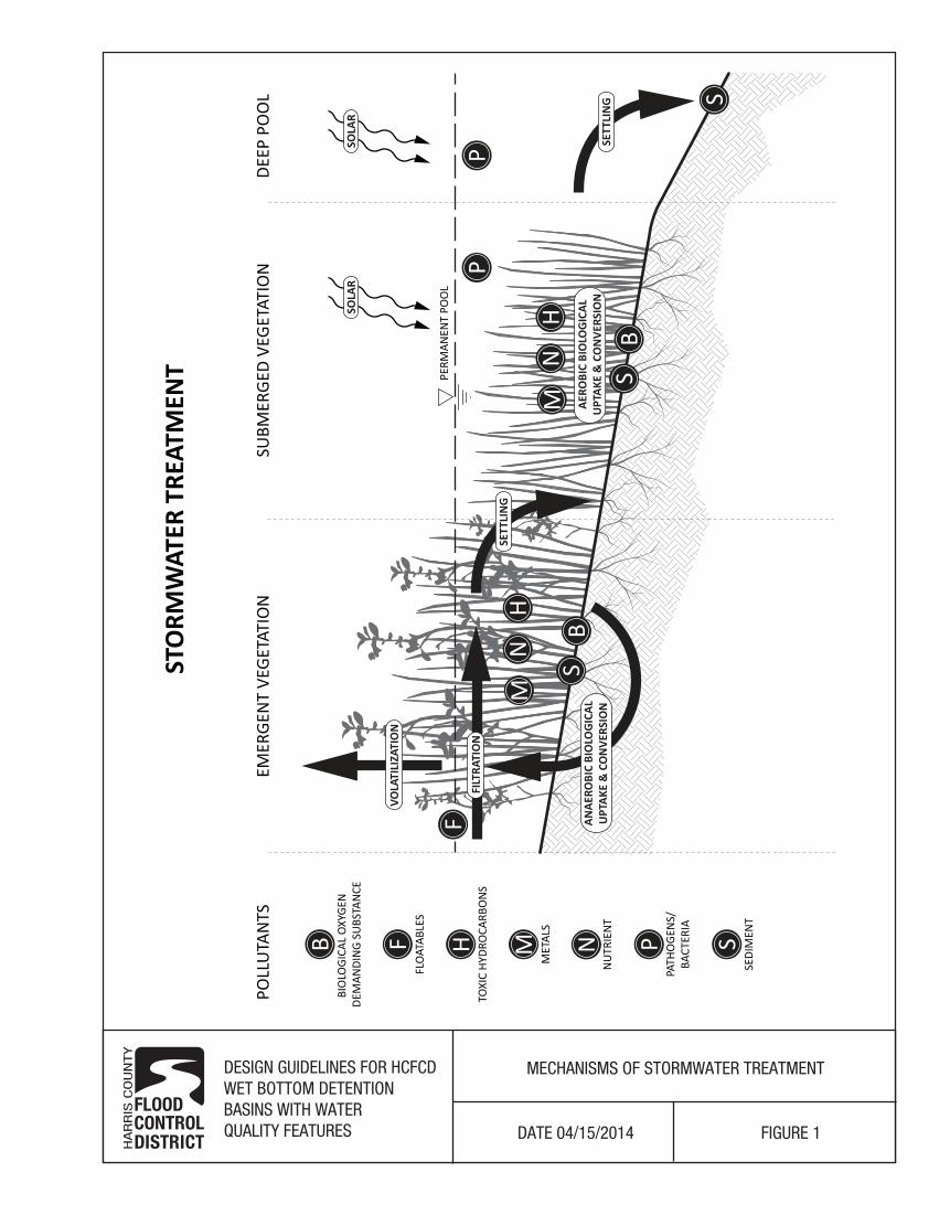
Suspended stormwater pollutants are primarily removed in wet bottom detention basins through settling in the facilities’ permanent pool. The efficiency of this settling is a function of particle velocity, fluid density, fluid viscosity, and particle diameter and shape. Refer to Section 5.6.3 for further details on residence time. Another factor that may influence the efficiency of settling, especially in areas with clay-silty sediments, includes the time available for particles to undergo settling. Settling may also be a function of the properties of the clay particles and whether they are suspended in a dispersed fashion or clumped together as floc (EPA, 2000). Secondary mechanisms for nutrient and pollutant removal include filtration of suspended solids by vegetation, infiltration, biological uptake of nutrients by aquatic plants and algae, volatilization of organic compounds, uptake of metals by plant tissue, and biological conversion of organic compounds (EPA, 2000). An illustration of the mechanisms for stormwater treatment is shown in Figure 1. Pollutants such as metals, hydrocarbons, nutrients, and biochemical oxygen demanding (BOD) substances can be adsorbed to sediment or attached to particulate matter that settles out. Nutrients and other contaminants attached to particulate matter which becomes trapped by wetland vegetation through filtration can be used by aquatic plants for growth. Organic contaminants can be broken down by the action of aquatic microorganisms (aerobic and anaerobic) while the open pool provides the necessary conditions for volatilization and degradation of a variety of organic compounds. Additionally, bacteria and pathogens are reduced in number through exposure to solar radiation. Refer to Appendix F – References and Resources for further information.
Continued on next page
DESIGN GUIDELINES FOR HCFCDWET BOTTOM DETENTIONBASINS WITH WATERQUALITY FEATURES
MECHANISMS OF STORMWATER TREATMENT
DATE 04/15/2014 FIGURE 1
STO
RMW
ATER
TRE
ATM
ENT
NB
B
PH M
EMER
GEN
T VE
GETA
TIO
NPO
LLU
TAN
TSSU
BMER
GED
VEGE
TATI
ON
DEEP
PO
OL
SETT
LIN
G
SETT
LIN
G
MET
ALS
S
SN
B
P
HM
NH
M
S
SSE
DIM
ENT
F
FFL
OAT
ABLE
S
TOXI
C HY
DRO
CARB
ON
S
PATH
OGE
NS/
BACT
ERIA
PERM
ANEN
T PO
OL
NU
TRIE
NT
BIO
LOGI
CAL
OXYG
EN
DEM
ANDI
NG
SUBS
TAN
CE
ANAE
ROBI
C BI
OLO
GIC
ALU
PTAK
E &
CO
NVE
RSIO
N
AERO
BIC
BIO
LOG
ICAL
UPT
AKE
& C
ON
VERS
ION
VOLA
TILI
ZATI
ON
SOLA
R
P
SOLA
R
FILT
RATI
ON

Design Guidelines for HCFCD Wet Bottom Detention Basins with Water Quality Features
12 HCFCD – April 2014
Section 4.0 – Project Planning, Continued
4.3 Water Quality Objectives
As a planning tool, HCFCD uses a screening method to determine water quality objectives for each of the twenty-two (22) watersheds in Harris County (HCFCD, 2011). Water quality objectives are expressed as water quality (WQ) enhancement opportunities based on subwatershed properties, including: degree of development, time of concentration, and position within the overall watershed. Analysis of these properties allows each watershed to be divided into WQ opportunity regions, as defined below. • Limited Opportunity Region – areas with higher percent imperviousness,
higher amounts of development, shorter times of concentration, and those located in downstream portions of the overall watershed.
• Moderate Opportunity Region – areas with medium percent imperviousness, moderate amounts of development, mid-range times of concentration, and those located in midstream portions of the overall watershed.
• High Opportunity Region – areas with lower percent imperviousness, lower amounts of development, longer times of concentration, and those located in upstream portions of the overall watershed.
WQ opportunity regions are delineated for each watershed, and a set of preferred planning-level conveyance (channel) and storage (detention) BMPs are assigned to each WQ opportunity region (HCFCD, 2011). The WQ opportunity region assignment and preferred BMP alternatives for the project area are provided to the project planner in the Preliminary Environmental Evaluation Report (PEER) and the Watershed Environmental Baseline (WEB) Map. Refer to Section 5.4 – Environmental Compliance for additional information on the WEB Map.
Continued on next page
NOTE:
Refer to the HCFCD Water Quality (WQ) Opportunity Planning Tool (HCFCD, 2011) for further guidance.
Criteria:
The MS4 permit (Refer to Section 2.0 – Regulatory Framework) requires consideration of water quality enhancement features. WQ opportunity region assignment and consideration of potential BMP alternatives for the opportunity region satisfies permit requirements. Formal documentation of WQ objectives is accomplished through the following, which are maintained in the project files:
• The PEER, and • The Feasibility Report.

Design Guidelines for HCFCD Wet Bottom Detention Basins with Water Quality Features
13 HCFCD – April 2014
Section 4.0 – Project Planning, Continued 4.3 Water Quality Objectives, continued
A list of site-specific water quality enhancement features for detention basins is based on the appropriate BMPs for each WQ opportunity region and available ROW. Consider inclusion of these features in the detention basin design in the context of the basin’s primary purpose, flood damage reduction. Water quality enhancement features can be stacked within one detention basin facility depending upon site-specific objectives, as shown below.
Continued on next page
Consideration:
Select one or multiple project features based on water quality opportunity region:
• Limited Opportunity Region □ Permanent pool □ Floatable materials control device
• Moderate Opportunity Region
□ Permanent pool □ Floatable materials control device □ Extended detention with water quality orifice at outflow □ Variable basin side slopes
• High Opportunity Region □ Permanent pool □ Floatable materials control device □ Extended detention with water quality orifice at outflow □ Variable basin side slopes □ Extensive stormwater treatment wetlands
NOTE:
The list of project features above is intended as a guideline. The design team is encouraged to also include vegetated shelves and features for multi-objective uses, where possible.

Design Guidelines for HCFCD Wet Bottom Detention Basins with Water Quality Features
14 HCFCD – April 2014
Section 4.0 – Project Planning, Continued
4.4 Preliminary Project Siting and Sizing
For planning stage analysis, the location and size of all detention facilities are primarily driven by flood damage reduction goals. Water quality enhancement considerations may be incorporated into location and sizing criteria by evaluating water quality feature options alongside flood damage reduction goals. In siting a wet bottom detention basin for stormwater quality enhancement, the project planner should look for opportunities to intercept storm sewer inflows and lateral channel inflows so that they enter the basin away from the outfall, thereby preventing short-circuiting of the treatment systems. In sizing the basin, the project planner can generally accommodate water quality features, such as a permanent pool, with a deeper overall basin depth. Additionally, accommodate varying side slopes and wider buffers for water quality enhancement by using flatter side slopes and wider maintenance berms, if ROW permits.
Continued on next page
Criteria:
To accommodate multiple water quality features and vary side slopes for site stability and multi-objective uses, recommend expanded rights-of-way for wet bottom detention basins, where practicable. Document planning-level decisions regarding inclusion of water quality enhancement features in detention basins in the Feasibility Report.
Consideration:
Consider 5:1 side slopes or flatter and a 50-foot maintenance berm during project planning to allow enough ROW to accommodate water quality features and other potential multi-objective uses.
NOTE:
As with any proposed HCFCD related land use, due diligence is performed to investigate environmental and other concerns associated with a specific parcel. While preliminary screening is required at a minimum during project planning, discussion of screening level and site-specific investigations to be performed is found in Section 5.0 – Project Development. Field visits to prospective detention basin sites are necessary during project planning.

Design Guidelines for HCFCD Wet Bottom Detention Basins with Water Quality Features
15 HCFCD – April 2014
Section 4.0 – Project Planning, Continued
4.5 Procedure – Project Planning
The following procedural guidance is geared to a general HCFCD detention basin project. Additional requirements for project planning may be necessary depending on the scale of the project, potential partnering options, and funding. * See Appendix A for complete list of Design Procedure steps.
Step* Action Tools/Reference 1 Gain a basic understanding of
stormwater wetland treatment systems. Refer to Section 4.2 and Resources in this manual, and the Bibliography at: http://www.nal.usda.gov/wqic/Constructed_Wetlands_all/cwur.html.
2 Establish project-specific water quality objectives. Document selection of water quality feature alternatives to include in the detention basin in the PEER and Feasibility Report.
Refer to HCFCD Water Quality (WQ) Opportunity Planning Tool (HCFCD 2011).
3 Identify a project site and develop a planning level layout based on flood damage reduction goals, water quality objectives, and other multi-objective uses, if applicable. Document decisions and keep a record throughout the planning process.
Coordination with HCFCD Strategic Planning Department and Stormwater Quality Department.
4 Perform screening-level investigations of contributing watershed and geotechnical data. Conduct preliminary due diligence on environmental site conditions.
Refer to Section 5.4 in this manual for more details.
5 Conduct a site visit during project planning to identify any potential site constraints not observed through preliminary due diligence.
Consult HCFCD Safety Handbook and INF Safety Procedure Manual on District SharePoint.
NOTE:
Follow these steps for each basin alternative being evaluated.

Design Guidelines for HCFCD Wet Bottom Detention Basins with Water Quality Features
16 HCFCD – April 2014
This page intentionally left blank

Design Guidelines for HCFCD Wet Bottom Detention Basins with Water Quality Features
17 HCFCD – April 2014
Section 5.0 – Project Development
5.1 Overview
Through project planning, the design team has defined the project goals, objectives, alternatives, size constraints, and recommended siting and layout options for the detention basin. All of this information serves as the springboard for the Project Development Stage. Project Development includes preliminary engineering and initial basin layout based on flood damage reduction requirements and water quality objectives. This section of the Design Guidelines provides: • Section 5.2 – Project Development Considerations. Overview of factors to
consider in developing a wet bottom detention basin with water quality features;
• Section 5.3 – Watershed Inputs. Determination of potential pollutant loading issues;
• Section 5.4 – Environmental Compliance. Environmental factors to consider in project development. (Screening-level due diligence and site visits are required during project planning and are documented in a reconnaissance report or feasibility report. All information pertaining to these activities are summarized in this section);
• Section 5.5 – Geotechnical Investigations. Discussion of soil stability and groundwater studies;
• Section 5.6 – Water Sources & Volumes. Discussion of water inputs and volume calculations to document support of a wet bottom detention basin;
• Section 5.7 – Preliminary Basin Layout. Initial design and decision making regarding level of water quality treatment to be included in flood damage reduction design;
• Section 5.8 – Project Development Reporting. Requirements for documenting water quality considerations in the Project Development Report/Preliminary Engineering Report; and
• Section 5.9 – Project Development Procedures. Compilation of procedures to follow during project development.

Design Guidelines for HCFCD Wet Bottom Detention Basins with Water Quality Features
18 HCFCD – April 2014
Section 5.0 – Project Development, Continued
5.2 Project Development Considerations
Overall constraints and factors to be considered during project development are provided below. These factors are discussed in further detail within this and subsequent sections.
Continued on next page
Considerations:
Contributing Watershed Data • Watershed characteristics (topography, soils data, land use); • Preliminary hydrology and hydraulic modeling (including but not
limited to: time of concentration, diverted channel flow, overland, and/or storm sewer flow to the detention basin, detention basin storage capacity to reduce flood damages);
• Water quality volume (permanent pool and extended detention goals); • Pretreatment requirements (sediment forebay, floatable materials
control, impairments).
Site Conditions • Watershed Environmental Baseline (WEB); • Water balance (inflow vs. outflow); • Existing and proposed ROW; • Existing and future roads, pipelines, and utilities; • Environmental Site Assessment (Phase I at minimum) results for
property acquisition; • Soil and groundwater conditions; • Environmental features such as jurisdictional wetlands, riparian
habitat, forested areas, or other significant resources; • Inflow sources for treatment potential.
Layout Requirements • Grading and depth requirements; • Preliminary geometric design criteria; • Location of inflow(s), outflow controls, and emergency overflow
structures; • Maintenance access and safety requirements; • Multi-objective uses, such as recreation (active and passive); • Site stabilization and revegetation; • Environmental mitigation requirements.

Design Guidelines for HCFCD Wet Bottom Detention Basins with Water Quality Features
19 HCFCD – April 2014
Section 5.0 – Project Development, Continued
5.3 Watershed Inputs
Where feasible, potential pollutant loading to the detention basin is evaluated. Evaluation of nutrient loading in particular can determine the possibility of eutrophic conditions developing in the permanent pool. Nutrient data are obtained from grab sampling or existing data. Existing data is available from the Houston Galveston Area Council (HGAC) Clean Rivers Program (CRP)1 or from special research, such as total maximum daily load (TMDL) studies for local water bodies.2 Pollutant loadings are strongly correlated with total suspended solid loads. Peak concentrations of all constituents are observed in the early part of storm events (or “first flush”) when solids are washed from the watershed (Southern California Coastal Water Research Project [SCCWRP], 2007). Bacteria impairments are present within most watersheds of Harris County. The District developed a Bacteria Reduction Plan (BRP) as part of its SWMP to address bacteria TMDLs (HCFCD, 2010b). The Bacteria Implementation Group (or BIG) has also developed a regional Implementation Plan (I-Plan) in response to the bacteria TMDLs.3 Consult Stormwater Quality Department (SQD) staff to determine what requirements for bacteria monitoring, screening, or research are needed, if any, within the proposed project watershed.
Continued on next page
1 HGAC Clean Rivers Program http://www.h-gac.com/rds/water_quality/default.aspx 2 TMDL studies http://www.tceq.state.tx.us/implementation/water/tmdl/ 3 The BIG and I-Plan Activities http://www.h-gac.com/community/water/tmdl/big/default.aspx
Considerations:
If nutrient loading to the facility exceeds surface water quality standards (TCEQ 2010) or if physical observations such as odor and visible algal blooms indicate high nutrient loading from wildlife and other natural sources, then:
• Evaluate the opportunity for passive aeration in project design. Refer to Section 6.5.2 – Water Circulation within the Basin
• Adjust plantings to utilize species with high nutrient removal capabilities and low wildlife habitat values. Refer to Appendix D for a list of potential plant species.
Consideration:
Consider including a sediment forebay to receive the first flush and trap sediment where extensive sedimentation is anticipated. Refer to Section 5.7.2 – Sediment Forebay, for further guidance on consideration of forebays.

Design Guidelines for HCFCD Wet Bottom Detention Basins with Water Quality Features
20 HCFCD – April 2014
Section 5.0 – Project Development, Continued
5.4 Environmental Compliance
Site investigations are necessary throughout the Project Development and ROW Acquisition Stages. Through these investigations, critical environmental issues and other risks are determined for a property being considered as a detention basin site. In addition, these investigations lay the foundation for Project Development by collecting and examining necessary information to establish site constraints, opportunities, and potential for water quality features. The level of investigation detail required at the Project Planning and Project Development Stages will vary by project and will depend on available data. Sources of existing data may include previous watershed studies, previous and ongoing site investigations, and review of existing baseline environmental data within HCFCD's Watershed Environmental Baseline (WEB) program.4
Continued on next page
4 HCFCD's WEB program documents the baseline environmental conditions of Harris County's watersheds in a preliminary report format and allows the user to evaluate various alternatives for a particular project. The WEB program's reporting system enables users to generate either a Preliminary Environmental Evaluation Report based on existing WEB data or a Preliminary Environmental Report based on a combination of WEB data and user-entered data.
Criteria:
Use the HCFCD WEB program to gather important data on existing conditions that:
• Identifies stream segments that maintain high natural habitat values in order to avoid degradation as part of future flood damage reduction measures.
• Distinguish between floodplain tracts that possess characteristics making them best suited for either regional stormwater detention basins or left alone and possibly preserved.
• Identifies environmentally sensitive areas, areas having other concerns such as contamination, or areas that others are working to preserve.
The design team must also visit the site(s) early in the project development stage with HCFCD Environmental Services Division (ESD) staff to obtain first-hand information about the prospective detention basin and to fill in any data gaps.
NOTE: Access to the WEB Program is provided to HCFCD staff only. However, WEB reports will be available to the design consultants/engineers upon request during project planning. Additional information on the WEB can be found at http://www.hcfcd.org/webprogram.html

Design Guidelines for HCFCD Wet Bottom Detention Basins with Water Quality Features
21 HCFCD – April 2014
Section 5.0 – Project Development
5.4 Environmental Compliance, continued
Once a property is considered for acquisition, an environmental site assessment (ESA) is required. Based on the results of a Phase I ESA, a Phase II ESA may be necessary to further investigate the level of risk associated with the property. In addition to the WEB program analysis and ESAs performed during the project development stage, further studies are required when developing a detention basin project. At a minimum, compliance with the appropriate federal, state, and local environmental rules, laws, regulations, and permits is required when modifying or constructing HCFCD facilities.
Continued on next page
Criteria:
The design team is required to comply with the following environmental regulations, as applicable:
• National Environmental Policy Act (NEPA); • Clean Water Act (CWA) §402; • CWA §404; • Endangered Species Act (ESA); • National Historic Preservation Act (NHPA); • Antiquities Code of Texas; and • Migratory Bird Treaty Act (MBTA).
NOTE:
The design team is required to check, review, and verify all facts and important aspects of environmental reports and regulations, with assistance from HCFCD Regulatory Compliance Department (RCD), before proceeding with the design process. See Appendix B2 for additional details on environmental regulations.
Criteria:
A Phase I ESA is required for any site under consideration for acquisition. Depending upon the outcome of the Phase I ESA, a Phase II ESA may also be required. The design engineer should consult with the Regulatory Compliance Department (RCD) for additional guidance.

Design Guidelines for HCFCD Wet Bottom Detention Basins with Water Quality Features
22 HCFCD – April 2014
Section 5.0 – Project Development
5.5 Geotechnical Investigations
A geotechnical investigation is required to characterize the potential soil conditions of the ultimate detention basin, and to determine if the design permanent pool elevation may be sustained at the site. These factors are integral to designing water quality features within the detention basin. Previous investigations can be used, if applicable.
Continued on next page
Criteria:
The geotechnical investigation must address at a minimum the following:
• Stability of the basin side slopes for short- and long-term conditions, taking into consideration location of permanent pool;
• Stability of the permanent pool side slopes; • Evaluation of bottom instability due to excess hydrostatic pressure; • Groundwater table and its variability; • Identification of dispersive soils; • Potential erosion problems; • Constructability issues; and • Evaluation of seepage (natural clay liner and/or sealing agents, if
needed).
NOTE:
The design engineer must follow HCFCD's Geotechnical Investigation Guidelines, provided in Appendix D of the HCFCD Policy, Criteria, and Procedure Manual for Approval and Acceptance of Infrastructure (HCFCD, 2010c) or the most current geotechnical guidelines approved by HCFCD.

Design Guidelines for HCFCD Wet Bottom Detention Basins with Water Quality Features
23 HCFCD – April 2014
Section 5.0 – Project Development
5.6 Water Sources & Volumes
The success of water quality features within stormwater detention basins are influenced by a variety of factors, the most critical being timing and amount of inputs from the water sources and the detention volumes. Wet bottom facilities are designed to provide storage for a water quality volume as well as flood damage reduction volume. Water quality enhancement is provided, at a minimum, by a permanent pool volume and may also include an extended detention water volume detained by a stormwater quality weir and orifice. The permanent pool volume and the extended detention volume represent the water quality volume and are stacked under the flood damage reduction storage. Refer to Figure 2 for an illustration of the water stages within a wet bottom detention basin.
Continued on next page
IMPORTANT NOTE:
This definition for the water quality volume is different than that provided in the JTF Criteria (Storm Water Quality Management Guidance Manual, 2001 Edition, prepared by the City of Houston, Harris County, and the Harris County Flood Control District and the Minimum Design Criteria for Implementation of Certain Best Management Practices for Storm Water Runoff Treatment Options, 2001 Edition.) The new definition is consistent with the current national approach to defining and estimating water quality volumes for detention facilities.

DESIGN GUIDELINES FOR HCFCDWET BOTTOM DETENTIONBASINS WITH WATERQUALITY FEATURES
STORAGE STAGES OF A WET BOTTOM BASIN
DATE 04/15/2014 FIGURE 2A
INFL
OW
OU
TFLO
WPE
RMAN
ENT
POO
L (V
pp)
WAT
ER Q
UALI
TY V
OLU
ME
(Vw
q)
FLO
OD
DAM
AGE
REDU
CTIO
NST
ORA
GE
VOLU
ME
(Vfd
r)
EXTE
NDE
D DE
TEN
TIO
N (V
ed)
REF.
FIG
URE
2B
STO
RAG
E ST
AGES

DESIGN GUIDELINES FOR HCFCDWET BOTTOM DETENTIONBASINS WITH WATERQUALITY FEATURES
CONCEPTUAL STORMWATER OUTFALL
DATE 04/15/2014 FIGURE 2B
MAINTENANCEACCESS (OPTIONAL)
OUTFLOW PIPE
BOTTOM SHELFVEGETATED SHELF
RESTRICTORORIFICE
TOP OF BANK
CONCRETE WEIR
CONCEPTUAL STORMWATER OUTFALL
F L O W

Design Guidelines for HCFCD Wet Bottom Detention Basins with Water Quality Features
26 HCFCD – April 2014
Section 5.0 – Project Development
5.6.1 Water Sources
For wet bottom detention basins that are intended to support a permanent pool and wetlands for water quality enhancement, it is important to determine the sources of water and the contributing volumes. Sources of water to maintain the permanent pool may include:
• Groundwater (via natural connection) • Surface Water
o Perennial stream flows o Stormwater runoff o Permitted wastewater treatment discharge
All of these water sources are considered in developing a water balance to predict the water elevations in the detention basin. Methods to determine groundwater and surface water inputs are provided below, followed by detailed information on determining the water volumes and verifying water balance for a wet bottom basin for water quality enhancement.
5.6.1.1 Groundwater
Borings for permanent piezometers may be made at the periphery of the basin during geotechnical investigations. The location of piezometer installation shall be coordinated with the HCFCD SQD and the Geotechnical Task Manager. Post-construction monitoring of groundwater may continue by SQD using these permanent piezometers to document any changes in groundwater levels. Once monitoring is complete, plugging and proper abandonment of piezometers is required. Poorly constructed piezometers and improperly abandoned piezometers can act as a conduit for groundwater contamination.5
Continued on next page
5 Abandoned wells are regulated by the Water Well Drillers Program of Texas Department of Licensing and Regulation ("TDLR") and local Groundwater Conservation Districts through Texas Occupations Code, Sections 1901.255 and 1901.256.
Criteria:
Groundwater is the preferred source for maintaining the permanent pool in HCFCD wet bottom detention basins. Monitor groundwater monthly utilizing a minimum of three site-specific piezometers at least two years prior to basin design. Refer to the Data Collection and Review Guidelines for Siting and Preliminary Engineering of Stormwater Quality Pond Systems in Harris County (Weston, 2002), for additional information on groundwater characterization.

Design Guidelines for HCFCD Wet Bottom Detention Basins with Water Quality Features
27 HCFCD – April 2014
Section 5.0 – Project Development
5.6.1.1 Groundwater, continued
5.6.1.2 Surface Water
Consider surface water as a source for maintaining the permanent pool if no groundwater sources are available. A permanent pool cannot be sustained from stormwater runoff alone and must include some perennial surface flow. Consider the limits and constraints of water rights regulations, as applicable. Review a minimum of five years of historic surface water flow conditions. United States Geological Survey (USGS) and Harris County Flood Alert gages are available to determine historic seasonal flows and mean water levels. If a gage is not located near the site, then local rainfall data may be incorporated into HCFCD watershed models to determine flow conditions. Investigation of channel vegetation and ordinary high water marks is recommended to evaluate surface flow to substantiate gage data or when no gage data is available.
Continued on next page
Consideration:
If groundwater is used as a source for the permanent pool:
• The historic seasonal low groundwater table is used in the water balance equation for determining the surface elevation of the permanent pool.
• The historic seasonal groundwater table should have low variability. The variability should be sufficiently low to maintain wetland vegetation within and around the permanent pool.
Criteria:
If surface water will be used as a source for the permanent pool:
• Use historic seasonal low flow for the permanent pool design elevation. • Ensure the watershed used for historic low flow modeling represents
stable conditions with minimal construction activities anticipated.
NOTE:
If the watershed is undergoing development, then design the basin for interim conditions, as needed, with an ultimate basin design also considered and developed. The interim detention basin may include water quality features.

Design Guidelines for HCFCD Wet Bottom Detention Basins with Water Quality Features
28 HCFCD – April 2014
Section 5.0 – Project Development
5.6.2 Water Volume Calculations
There are two water quality storage stages within a wet bottom detention facility operating on gravity flow: the permanent pool (the elevation of the water quality orifice invert) and the extended detention stage (elevation of the crest of the stormwater quality weir with orifice). The extended detention volume defines a volume retained above the permanent pool for a period dictated by the configuration of the stormwater quality weir/orifice structure (Figure 2). Methodology used to estimate the water quality, permanent pool, and extended detention volumes are presented below.
5.6.2.1 Water Quality Volume
Use the 90% rainfall event method, described below, to calculate water quality volume. The 90% storm event is greater than or equal to 90% of all 24-hour storms on an annual basis. This method has been calibrated to our region and successfully applied on many previous projects by the District. The 90% rainfall event method does not rely on any assumptions about pollutant loading or the timing of pollutant loads during a runoff event. The rainfall analysis performed with records from Houston Intercontinental Airport (IAH) shows 90% of the annual rainfall events to be 1.75 inches or less in 24 hours. Therefore, the value of 1.75 inches is used in calculation of water quality volume (Vwq). Determine Vwq by multiplying 1.75 inches of rainfall by the runoff coefficient and watershed area. This volume is allocated between the permanent pool volume and extended detention volume, as discussed in the following subsection. Additional details on the procedures for calculating the water quality volume are provided in Appendix C1. These calculations are presented in general terms, and the design team is responsible for assuring applicability to watershed and site-specific conditions.
Continued on next page
NOTE:
Appendix C1 also presents alternative methods to the 90% rainfall event method for calculating the water quality volume, however, these alternative methods require approval from SQD.

Design Guidelines for HCFCD Wet Bottom Detention Basins with Water Quality Features
29 HCFCD – April 2014
Section 5.0 – Project Development
5.6.2.2 Permanent Pool Volume
The permanent pool volume represents the component of the water quality volume stored within a wet bottom detention basin between storm events. This volume is considered treated storage and is discharged from the basin during the next storm event. The detention basin drainage area is used to determine the permanent pool volume.
Small Drainage Areas (approximately 300 acres or less) – In small drainage areas, the 90% rainfall event runoff volume (Vwq) can generally be allocated to the permanent pool volume (Vpp). If all of the water quality volume is allocated to the permanent pool, provisions for extended detention and the utilization of a stormwater quality weir and orifice structure is optional. Large Drainage Areas (approximately 300 acres or greater) – For large drainage areas, sizing the permanent pool to provide all of the estimated water quality volume may not be feasible. In these instances, the water quality volume is allocated between the permanent pool volume and extended detention volume. For large watersheds, storm events of any significant size will overtop the water quality features. As the basin drains, the last water to exit the basin is treated as it is detained by the water quality orifice structure, allowing sediment to settle and other stormwater treatment processes to occur. This will result in some water quality benefits. For these large drainage areas, the permanent pool volume is optimized by maximizing the areal extent of the water quality feature. This is accomplished by using as much of the basin floor as possible while conforming to the geometric requirements outlined in the PCPM and Section 6.0 – Project Design; namely flood damage reduction criteria, multi-use features, length-to-width ratios, inflow and outflow locations, and the use of multiple ponds.
Continued on next page
Criteria:
Depending upon drainage area size, the permanent pool volume is either: • Equal to the water quality volume where possible (Small); or • Equal to an optimum percentage where the permanent pool area is
maximized and the additional water quality volume is assigned to extended detention (Large).

Design Guidelines for HCFCD Wet Bottom Detention Basins with Water Quality Features
30 HCFCD – April 2014
Section 5.0 – Project Development
5.6.2.3 Extended Detention Volume
The extended detention volume represents the component of the water quality volume surcharged on top of the permanent pool and below the flood damage reduction storage volume of a wet bottom detention basin. The choice in extended detention volume is dependent upon the drainage area size, water quality volume, and permanent pool volume, as described above. The design of outflow control structures is covered in Section 6.5 – Outflow Structures.
5.6.3 Residence Time
Stormwater quality treatment in a wet bottom detention basin is primarily achieved through sediment settling and biological activity within the permanent pool. Further settling will occur during the time that the extended detention volume is retained onsite. The efficiency of the pollutant removal process is dependent upon the length of time that runoff remains within the detention facility. Contact with treatment wetlands over an extended period also allows further stormwater quality enhancement. The length of time that runoff remains within the permanent pool is known as the Hydraulic Residence Time (HRT), a function of the permanent pool volume and geometry.
Continued on next page
Criteria:
The extended detention volume is either:
• Equal to 50% of the water quality volume where the remaining 50% of the water quality volume is allocated to the permanent pool (EPA 1999a); or
• Equal to an optimum percentage where the additional water quality volume is assigned to the permanent pool using the design engineer’s best professional judgment.
Criteria:
Design HCFCD wet bottom detention basins with water quality features to accommodate the extended detention volume for a minimum HRT of 24 hours.

Design Guidelines for HCFCD Wet Bottom Detention Basins with Water Quality Features
31 HCFCD – April 2014
Section 5.0 – Project Development
5.6.3 Residence Time, continued
5.6.4 Water Balance
A water balance accounts for flow into and out of the detention basin. The elevation of the permanent pool should be sufficient throughout the year to provide a source of water to sustain wetland plants at the fringe and to assure that the bottom substrate is not compromised. Wetland plants will stabilize the bottom substrate and minimize turbulence within the pond.
Continued on next page
Considerations:
One or more of the following considerations can achieve a relatively high residence time within the detention facility:
• A circuitous or prolonged flow path; • Adding diversion barriers and baffles, such as islands, peninsulas, or
submerged berms; • Vegetated shelves designed and populated with appropriate wetland
vegetation in accordance with Section 6.8 - Vegetated Shelf and Section 8.3 - Wetland Planting;
• Use of multiple ponds in series and separate pools with berms and vegetated shelves (where possible, use of a gradient change between ponds of 6 inches to encourage flow through the system); and
• A stormwater quality weir and orifice structure designed in accordance with Section 6.5.1 - Multiple Frequency Outflow Structures.
Criteria:
A water balance calculation of the inflows and outflows is required to demonstrate the presence of sufficient water to support a permanent pool and beneficial wetlands in the basin. Use the methods described below.

Design Guidelines for HCFCD Wet Bottom Detention Basins with Water Quality Features
32 HCFCD – April 2014
Section 5.0 – Project Development
5.6.4 Water Balance, continued
Calculate: The historic seasonal groundwater table and/or the historic seasonal low flow condition is used with water balance calculations. The water balance calculation is given as:
∑∑ −=∆∆
outin QQtS
( ) ( )∑ ∑∑ ∑ −=−∆=∆ outinoutin VVQQtS
where: ΔS = change in storage on a control volume [permanent pool
volume] Δt = time interval (t) Qin = inflows into the control volume (volume/t) Qout = outflows out of the control volume (volume/t) Vin = volume into the control volume Vout = volume out of the control volume Adjust: Once the water quality, permanent pool, and extended detention volumes are determined, adjust the pond and basin finished grade elevations to achieve the desired volumes. This iterative process requires volumes to be readjusted based on geometric layout. Refer to Section 6.0, - Project Design, and Appendix A - Design Procedures. Refer to the Resources section to find data on evaporation and evapotranspiration.
Continued on next page
Considerations:
At a minimum, the following inflows and outflows should be considered during water balance calculations:
• Inflows: baseflow, groundwater, runoff, stream inflows, and pipe structures (may be from storm sewer or outlet channel).
• Outflows: infiltration, evaporation, evapotranspiration, pipe structures, and control structures.

Design Guidelines for HCFCD Wet Bottom Detention Basins with Water Quality Features
33 HCFCD – April 2014
Section 5.0 – Project Development
5.7 Preliminary Basin Layout
During the Project Development Stage, develop a general basin layout and decide how to handle sediments entering the basin. This section provides general basin layout criteria including:
• Basin geometry for various levels of WQ enhancement opportunities; • Sediment forebay requirements.
Once the general basin layout is developed, refine the design according to the PCPM and these Design Guidelines, Section 6.0 – Project Design.
5.7.1 Basin Geometry
Overall basin geometry is defined by:
• Basin length-to-width ratio; • Basin side slopes; • Minimum permanent pool depths; • Basin bottom width and length; • Calculated permanent pool volume; • Calculated extended detention volume; • Optional forebay; • Bottom shelf; and • Vegetated shelves (or Shallow Pool as described in Section 6.4.8 of the
PCPM). A typical layout and profile of a wet bottom detention basin with water quality features in low, moderate, and high level WQ opportunity regions is shown in Figures 3A, 3B, and 3C respectively. Refer to Section 4.3 – Water Quality Objectives for additional information on WQ opportunity regions. Layout criteria for a wet bottom basin are available in the PCPM (Section 6.4 - Layout). The layout and profile, as shown in Figures 3A-C, illustrates generalized criteria for the overall layout of the wet bottom detention facility, location of inflows relative to outflows, pond depths for the multiple ponds and pond connections, variations in side slopes, WQ enhancement features, such as forebays and vegetated shelves, and changes in water surface elevation from the inflow to the outflow.
Continued on next page
Consideration:
Consider habitat preservation during the preliminary basin layout, where practicable, to reduce revegetation costs. Refer to Section 8.5 – Habitat Preservation.

Design Guidelines for HCFCD Wet Bottom Detention Basins with Water Quality Features
34 HCFCD – April 2014
Section 5.0 – Project Development, Continued
5.7.1 Basin Geometry (continued)
Continued on next page
NOTE:
The design team is encouraged to coordinate with SQD and INF staff to develop the Basin Layout. Consider contracting a landscape architect to refine design elements.
Criteria:
Provide a preliminary basin layout and supporting calculations during Project Development and further refine it during Project Design. Consult conceptual landscape plans if previously prepared for the site.

DESIGN GUIDELINES FOR HCFCDWET BOTTOM DETENTIONBASINS WITH WATERQUALITY FEATURES
WET BOTTOM DETENTION BASIN WITH FOREBAY OPTIONIN A LIMITED OPPORTUNITY REGION
DATE 04/15/2014 FIGURE 3A
INFL
OW
OU
TFLO
W
HCFC
D M
AIN
TEN
ANCE
BERM
(MIN
. WID
TH 3
0 FT
.)
HCFCD R.O.W.
HCFCD R.O.W.
BURI
ED R
IP-R
AP
SEDI
MEN
T FO
REBA
Y(8
TO
10
FT. D
EEP)
MAI
NTE
NAN
CE A
CCES
S(M
IN. W
IDTH
20
FT.)
ALL
WEA
THER
MAI
NTE
NAN
CE
ACCE
SS (M
IN. W
IDTH
20
FT.)
EMER
GEN
CY O
VERF
LOW
DEEP
PO
OL
(6 T
O 8
FT.
DEE
P)
VEGE
TATE
D RI
P-RA
P GR
ADE
CON
TRO
L BE
RM(S
EE A
PPEN
DIX
E1)
WAT
ER Q
UALI
TYCO
NTR
OL
STRU
CTU
RE(R
EF. F
IGU
RE 2
B)SIDE
SLO
PES
(3H:
1V O
R FL
ATTE
R)
BACK
SLO
PE D
RAIN
AGE
SWAL
E
BOTT
OM
SHE
LF(M
IN. W
IDTH
10
FT.)
VEGE
TATE
D SH
ELF
(MIN
. WID
TH 1
0 FT
.)
VEGE
TATE
D RI
P-RA
P GR
ADE
CON
TRO
L BE
RMAL
L W
EATH
ERM
AIN
TEN
ANCE
ACC
ESS
(MIN
. WID
TH 2
0 FT
.)
BURI
ED R
IP-R
AP
MAI
NTE
NAN
CEPA
D TU
RNAR
OU
ND
BOTT
OM
SHE
LF(M
IN. W
IDTH
10
FT.)
MAI
NTE
NAN
CE A
CCES
S(M
IN. W
IDTH
20
FT.)
EMER
GEN
CYO
VERF
LOW
BACK
SLO
PE D
RAIN
AGE
SWAL
E
HCFC
D M
AIN
TAIN
EDCH
ANN
EL
INFL
OW
OU
TFLO
W
WET
BO
TTO
M D
ETEN
TIO
N B
ASIN
OPT
ION
A
TREA
TMEN
T FL
OW
PAT
H
PERM
ANEN
T PO
OL
WAT
ER Q
UALI
TY V
OLU
ME
FLO
OD
DAM
AGE
REDU
CTIO
N S
TORA
GEFR
EEBO
ARD
HCFC
D M
AIN
TAIN
EDCH
ANN
EL
FORE
BAY
BACK
SLO
PE IN
TERC
EPTO
RST
RUCT
URE

DESIGN GUIDELINES FOR HCFCDWET BOTTOM DETENTIONBASINS WITH WATERQUALITY FEATURES
WET BOTTOM DETENTION BASIN WITH FOREBAYOPTION IN A MODERATE OPPORTUNITY REGION
DATE 04/15/2014 FIGURE 3B
INFL
OW
OU
TFLO
W
VEGE
TATE
D SH
ELF
(MIN
. WID
TH 1
0 FT
.)
INFL
OW
OU
TFLO
W
HCFC
D M
AIN
TEN
ANCE
BER
M(M
IN. W
IDTH
30
FT.)
MAI
NTE
NAN
CE A
CCES
S(M
IN. W
IDTH
20
FT.)
SEDI
MEN
T FO
REBA
Y(8
TO
10
FT. D
EEP)
BURI
ED R
IP-R
AP
ALL
WEA
THER
MAI
NTE
NAN
CE
ACCE
SS (M
IN. W
IDTH
20
FT.)
DEEP
PO
OL
(6 T
O 8
FT.
DEE
P)
VEGE
TATE
D RI
P-RA
P GR
ADE
CON
TRO
L BE
RM(R
EF. A
PPEN
DIX
E1)
EMER
GEN
CY O
VERF
LOW
WAT
ER Q
UALI
TY C
ON
TRO
L ST
RUCT
URE
(REF
. FIG
URE
2B)
SIDE
SLO
PES
(3H:
1V O
R FL
ATTE
R)
BACK
SLO
PE D
RAIN
AGE
SWAL
E
BOTT
OM
SHE
LF(M
IN. W
IDTH
10
FT.)
VEGE
TATE
D SH
ELF
(MIN
. WID
TH 1
0 FT
.)
VEGE
TATE
D RI
P-RA
PGR
ADE
CON
TRO
LBE
RM
BACK
SLO
PE D
RAIN
AGE
SWAL
E
MAI
NTE
NAN
CEAC
CESS
(MIN
. W
IDTH
20
FT.)
ALL
WEA
THER
MAI
NTE
NAN
CE A
CCES
S (M
IN. W
IDTH
20
FT.)
BURI
ED R
IP-R
AP
MAI
NTE
NAN
CEPA
D TU
RNAR
OU
ND
BOTT
OM
SHE
LF(M
IN. W
IDTH
10
FT.)
EMER
GEN
CYO
VERF
LOW
BACK
SLO
PEIN
TERC
EPTO
RST
RUCT
URE
HCFC
D M
AIN
TAIN
ED
CHAN
NEL
PERM
ANEN
T PO
OL
WAT
ER Q
UALI
TY V
OLU
ME
FLO
OD
DAM
AGE
REDU
CTIO
N S
TORA
GE
FREE
BOAR
D
HCFCD R.O.W.
HCFCD R.O.W.
WET
BO
TTO
M D
ETEN
TIO
N B
ASIN
OPT
ION
B
TREA
TMEN
T FLO
W PA
THFO
REBA
Y

DESIGN GUIDELINES FOR HCFCDWET BOTTOM DETENTIONBASINS WITH WATERQUALITY FEATURES
WET BOTTOM DETENTION BASIN WITH FOREBAY OPTIONIN A HIGH OPPORTUNITY REGION
DATE 04/15/2014 FIGURE 3C
TREA
TMEN
T FL
OW
PAT
H
INFL
OW
OU
TFLO
W
INFL
OW
OU
TFLO
W
HCFC
D M
AIN
TEN
ANCE
BER
M(M
IN. W
IDTH
30
FT.)
MAI
NTE
NAN
CE A
CCES
S(M
IN. W
IDTH
20
FT.)
ALL
WEA
THER
MAI
NTE
NAN
CE
ACCE
SS (M
IN. W
IDTH
20
FT.)
BURI
ED R
IP-R
AP
DEEP
PO
OL
(6 T
O 8
FT.
DEE
P)
VEGE
TATE
D RI
P-RA
P GR
ADE
CON
TRO
L BE
RM(R
EF. A
PPEN
DIX
E1)
EMER
GEN
CY O
VERF
LOW
SEDI
MEN
T FO
REBA
Y(8
TO
10
FT. D
EEP)
WAT
ER Q
UALI
TY C
ON
TRO
L ST
RUCT
URE
(REF
. FIG
URE
2B)
BACK
SLO
PE D
RAIN
AGE
SWAL
E
MAI
NTE
NAN
CEPA
D TU
RNAR
OU
ND
BU
RIED
RIP
-RAP
ALL
WEA
THER
MAI
NTE
NAN
CEAC
CESS
(MIN
.W
IDTH
20
FT.)
BACK
SLO
PEDR
AIN
AGE
SWAL
E
MAI
NTE
NAN
CEAC
CESS
(MIN
.W
IDTH
20
FT.)
BOTT
OM
SHE
LF(M
IN. W
IDTH
10
FT.)
EMER
GEN
CYO
VERF
LOW
HCFC
DM
AIN
TAIN
ED
CHAN
NEL
BOTT
OM
SHE
LF(M
IN. W
IDTH
10
FT.)
VEGE
TATE
D SH
ELF
(MIN
. WID
TH 1
0 FT
.)
VEGE
TATE
DRI
P-RA
P GR
ADE
CON
TRO
L BE
RM
VEGE
TATE
D SH
ELF
(MIN
. WID
TH 1
0 FT
.)U
PLAN
DPR
ESER
VATI
ON
PERM
ANEN
T PO
OL
WAT
ER Q
UALI
TY V
OLU
ME
FLO
OD
DAM
AGE
REDU
CTIO
N S
TORA
GEFR
EEBO
ARD
HCFCD R.O.W.
HCFCD R.O.W.
WET
BO
TTO
M D
ETEN
TIO
N B
ASIN
OPT
ION
C
BACK
SLO
PEIN
TERC
EPTO
RST
RUCT
URE
FORE
BAY

Design Guidelines for HCFCD Wet Bottom Detention Basins with Water Quality Features
38 HCFCD – April 2014
Section 5.0 – Project Development
5.7.2 Sediment Forebay
A sediment forebay enhances the pollutant removal capabilities of the wet bottom detention facility by allowing the heavier, coarse-grained sediments and particulate pollutants to settle out before they are discharged to the remainder of the facility. The forebay is typically located at the inflow point to the basin and is designed to isolate sediment deposition in an accessible area. A survey of sedimentation rates for wet bottom detention basins in Harris County in 2006 indicated that basins with a forebay trap sediments in appreciable amount and benefit stormwater quality (TCB, 2006). Sediment forebays are recommended for wet bottom facilities that serve drainage areas determined to be contributing high concentrations of coarse-grained soils either by:
• The nature of the soils within the watershed, or • The anticipated degree of development or concentration of construction
sites within the drainage area. Watersheds containing coarse-grained soils that may be suitable for removal in a sediment forebay are shown in Figure 4. Coarse-grained soils are defined as soils where less than 50 percent of soil particles, as mapped in the Soil Survey of Harris County, pass through Sieve No. 200.6
Continued on next page
6 Refer to the Soil Survey of Harris County, Texas, published by the U.S Department of Agriculture Soil Conservation Service for additional information on Harris County soils (USDA 1976).
Criteria:
A project-specific analysis of drainage area, soil types, and particle size is required for project sites located within the HCFCD watersheds listed in Figure 4 with coarse-grained soils. The design team will decide if a sediment forebay is necessary during Project Development and determine its general size. Detailed design and configuration will be determined during Project Design, as described in Section 6.2 – Forebay Design Criteria and Alternatives.

Design Guidelines for HCFCD Wet Bottom Detention Basins with Water Quality Features
39 HCFCD – April 2014
Section 5.0 – Project Development, Continued
5.7.2 Sediment Forebay (continued)
5.7.3 Floatable Materials Collection
Floatable material and debris is a significant pollutant, maintenance, and aesthetic concern in HCFCD maintained detention basins and channels. Detention basins can serve as floatable collection devices themselves by providing an area for floatable materials to collect during storm events. The bulk of floatable materials enters detention basins through flood events and requires specialized effort to collect and dispose of properly to prevent re-suspension of floatable materials.
Continued on next page
Considerations:
Additional investigation of the development trends within the drainage area is also recommended to determine if a sediment forebay is needed. Research by the District showed that developing areas produce significant sediment loads with greater trapping efficiency achieved through off-site detention compared to on-site methods (HCFCD, 1985). Wet bottom facilities that are not located within the watersheds listed in Figure 4 or where inflows are conveyed in grassed channels without a high degree of development may not require a sediment forebay or one that is reduced in size.
Criteria:
The control and collection of floatables materials within wet bottom basins must be evaluated during Project Development with consideration given to:
• Watershed characteristics (urban versus undeveloped); • Number and location of inflows; and • Maintenance access to proposed floatables collection devices.
Refer to Section 6.9 – Floatable Materials Control Systems for design criteria.

DESIGN GUIDELINES FOR HCFCDWET BOTTOM DETENTIONBASINS WITH WATERQUALITY FEATURES
DISTRIBUTION OF COARSE-GRAINED SOILSWITHIN HARRIS COUNTY
DATE 04/15/2014 FIGURE 4
SPRING CREEKJ
SAN JACINTO RIVERG
CYPRESS CREEKK
CLEAR CREEKA
GREENS BAYOUP
BRAYS BAYOUD
SIMS BAYOUC
ADDICKS RESERVOIRU
BUFFALO BAYOUW
WHITE OAK BAYOUE
CEDAR BAYOUQ
BARKER RESERVOIRT
LUCE BAYOUS
ARMAND BAYOUB
WILLOW CREEKM
LITTLE CYPRESS CREEKL
HUNTING BAYOUH
JACKSON BAYOUR
CARPENTERS BAYOUN
VINCE BAYOUI
SPRING GULLY & GOOSE CREEKO
SAN JACINTO & GALVESTON BAYF
SAN JACINTO & GALVESTON BAYFLegend
Coarse-Grained Soils (<50% passing Sieve No. 200)
Watersheds with Optional Forebay Consideration
Watersheds with Mandatory Forebay Consideration
Harris County Boundary
HCFCD Watersheds with Coarse-Grained Soils:
Spring Creek (Main Channel: J100-00-00)Little Cypress Creek (Main Channel: L100-00-00)Cypress Creek (Main Channel: K100-00-00)Willow Creek (Main Channel: M100-00-00)Carpenter's Bayou (Main Channel: N100-00-00)
Greens Bayou (Main Channel: P100-00-00)San Jacinto River (Main Channel: G103-00-00)Jackson Bayou (Main Channel: R100-00-00)Luce Bayou (Main Channel: S100-00-00)Spring Gully & Goose Creek (Main Channels: O200-00-00 & O100-00-00)

Design Guidelines for HCFCD Wet Bottom Detention Basins with Water Quality Features
41 HCFCD – April 2014
Section 5.0 – Project Development
5.8 Project Development Reporting
HCFCD is obligated to consider if water quality enhancement can be incorporated into flood damage reduction facilities (Refer to Section 2.0 – Regulatory Framework). Water quality enhancement features may not be required for a detention basin where site conditions or other factors, including site topography, soils, hydrology, groundwater depths, or rainfall preclude practical implementation. Proper documentation of water quality consideration and rationale for elimination from further consideration during project feasibility and project development is required.
Continued on next page
Criteria:
Water quality enhancement consideration, including water quality objectives, is documented during project planning. (Refer to Section Section 4.3 – Water Quality Objectives.) If consideration of water quality objectives were not documented in the PEER, then documentation is required in the Project Development Stage as described below. Perform the detailed consideration, refinement, and evaluation of water quality objectives during project development and document the work and recommendations in the Project Development Report (PDR) or Preliminary Engineering Report (PER). Guidelines for development of the PDR/PER are covered in detail in the HCFCD Water Quality Enhancement Section Requirements for a Preliminary Engineering Report (PER) or Project Design Report (PDR) (HCFCD 2012).

Design Guidelines for HCFCD Wet Bottom Detention Basins with Water Quality Features
42 HCFCD – April 2014
Section 5.0 – Project Development
5.9 Procedure – Project Development
The following procedural guidance is followed during Project Development. Additional requirements for project development may be necessary depending on the scale of the project, potential partnering options, and funding.
Continued on next page
Step* Action Tools/Reference 1 Review and refine project goals and
objectives regarding water quality enhancement. Review contributing watershed data, site conditions, and project requirements.
Refer to Section 5.2 in this manual for a list of considerations.
2 Conduct a site visit and collect site-specific data, as needed. Evaluate data gaps.
Consult HCFCD Safety Handbook and INF Safety Procedure Manual on District SharePoint.
3 Evaluate watershed inputs of pollutants such as sediment, bacteria, nutrients, etc. Adjust project requirements according to potential pollutant loading.
Refer to Section 5.3 and Appendix C1 in this manual for additional information on load reduction.
4 Perform due diligence by confirming applicable local design criteria, environmental compliance, and permitting requirements for the project site.
Consult with HCFCD RCD and WEB Program. Refer to Section 5.4 in this manual and to Section 17 in the PCPM for Environmental Compliance.
5 Investigate potential geotechnical issues.
Use existing geotechnical and soil reports. Refer to Section 5.5 in this manual. Refer to the PCPM for geotechnical investigation guidelines.
6 Determine water sources for permanent pool. Install piezometers for groundwater monitoring on all projects. Determine historic seasonal low flow from gage data or other sources.
In this manual, refer to Section 5.6.1 for guidance on water sources, Section 5.6.1.1 for groundwater criteria, and Section 5.6.1.2 for surface water.

Design Guidelines for HCFCD Wet Bottom Detention Basins with Water Quality Features
43 HCFCD – April 2014
Section 5.0 – Project Development
5.9 Procedure – Project Development, continued
*See Appendix A for complete list of Design Procedure steps.
Continued on next page
Step* Action Tools/Reference 7 Based on the contributing watershed,
determine the water quality volume, detention volume, and size the WQ orifice and/or outlet control structure.
Refer to Section 5.6.2 in this manual for guidance on determining the water quality volume.
8 Determine the size and elevation of the basin inflow and outflow structures.
Refer to Section 6.6 and Section 6.7 of the PCPM for design guidelines.
9 Calculate water balance to demonstrate sufficient water to support permanent pool and enhancement features.
Refer to Section 5.6.4 in this manual for guidance on water balance calculations.
10 Develop preliminary detention basin layout with consideration for sediment forebay and floatables materials collection based on watershed inputs.
Refer to Section 5.7 in this manual and to Section 6.4 in the PCPM for criteria.
11 Prepare Project Development Report or Preliminary Engineering Report.
Refer to Section 5.8 in this manual for criteria.

Design Guidelines for HCFCD Wet Bottom Detention Basins with Water Quality Features
44 HCFCD – April 2014
This page intentionally left blank

Design Guidelines for HCFCD Wet Bottom Detention Basins with Water Quality Features
45 HCFCD – April 2014
Section 6.0 – Project Design
6.1 Overview
Initial design activities and investigations, culminating in the preparation of a Project Development Report (PDR) or Preliminary Engineering Report (PER), provides documented environmental and engineering analyses to assist the design team in making final design decisions. This section provides guidance on how water quality features are incorporated into the layout and design of the wet bottom detention basin. Generally, the PCPM is followed in designing the detention basin, however, for wet bottom basins that include water quality enhancement features there are additional criteria and considerations, as described in the following subsections: • Section 6.2 – Forebay Design Criteria and Alternatives. Includes specific
criteria for design and maintenance access to a forebay, as well as design of alternative features to trap sediments;
• Section 6.3 – Side Slope Configuration. Includes criteria for basin design with variable side slopes and gradual slope breaks;
• Section 6.4 – Inflow Structures. Provides considerations and criteria for the transition from inflow structure to water quality features;
• Section 6.5 – Outflow Structures. Provides criteria for sizing and designing outflow structures to accommodate water quality enhancement;
• Section 6.6 – Permanent Pool. Provides geometric and layout requirements for the permanent pool;
• Section 6.7 – Water’s Edge. Provides shoreline slope and permanent pool elevation relative to bottom shelf and vegetated shelf;
• Section 6.8 – Vegetated Shelf. Provides slope and layout requirements for submerged shelf to be vegetated (referred to as a Shallow Pool in Section 6.4.8 of the PCPM);
• Section 6.9 – Floatable Materials Control Systems. Provides criteria for including floatable materials control devices;
• Section 6.10 – Multi-Objective Uses. Provides considerations for including trails, boardwalks, fishing piers, habitat plantings and other features for public use, including safety;
• Section 6.11 – Water Quality Design Criteria Summary. Summarizes the wet bottom design criteria from the sections above; and
• Section 6.12 – Project Design Procedures. Compilation of procedures to follow during project design.
Continued on next page
Design Guidelines for HCFCD Wet Bottom Detention Basins with Water Quality Features
46 HCFCD – April 2014
Section 6.0 – Project Design, Continued
6.2 Forebay Design Criteria and Alternatives
Inclusion of a sediment forebay within a wet bottom detention facility is optional (Refer to Section 5.7.2 – Sediment Forebay, for considerations). If included in the facility, the sediment forebay volume is typically sized to 10% - 20% of the permanent pool volume (EPA, 2000; TCB, 2006). Depending on watershed characteristics, such as soil types or the degree of development, determine the need to allocate a smaller or greater percentage of the permanent pool volume to the sediment forebay. Alternatives to forebay features are discussed in Section 6.2.2 – Forebay Alternatives.
Continued on next page
Criteria:
Configure the sediment forebay to include:
• An all-weather maintenance access in accordance with Section 6.2.1 – Forebay Maintenance Access.
• A tear-shaped geometry with length-to-average width ratio of 3:1 and the inflow at the narrow end to allow for backhoe reach for sediment removal.
• A depth of 4 to 6 feet. • Permanent concrete desilt markers indicating when sediment removal is
needed and the limits of removal, if required. • Designs to dissipate energy and reduce velocity of the flow entering the
forebay through baffles, concrete riprap, or roughened apron. • Distinct sediment forebays, where applicable, for each separate inflow.
Design Guidelines for HCFCD Wet Bottom Detention Basins with Water Quality Features
47 HCFCD – April 2014
Section 6.0 – Project Design, Continued
6.2.1 Forebay Maintenance Access
Sediment forebay maintenance access is required so that desilting and other periodic maintenance activities may be performed. Consult with the HCFCD Infrastructure Division on specific design topics such as, provisions for the use of mats to cross the basin bottom during maintenance activities, and requirements for turnaround areas. Criteria for design of maintenance access to a wet bottom basin bottom can be found in the PCPM (Section 16.3.4 - All Weather Access Road).
6.2.2 Forebay Alternatives
Under conditions where a sediment forebay is not required or feasible (where substantial areas of coarse-grained soils do not exist), consider a vegetated shelf or series of shelves with wetland plantings near the basin inflow to reduce incoming flow velocities and trap particulate matter. Baffles, concrete riprap, or a roughened apron may also be used to dissipate energy and reduce flow velocity entering the permanent pool or vegetated shelf in cases when a forebay is not provided. Figure 3A shows a wet bottom facility with a vegetated shelf in lieu of a sediment forebay.
6.3 Side Slope Configuration
Use naturalistic side slopes and vary where possible. Variable side slopes increase the flow path of stormwater through the basin and contact with beneficial wetlands, thereby promoting water quality enhancement. Variable side slopes also improve aesthetics and provide additional recreational opportunities. The basin bottom shelf, the gently sloping area between the toe of the basin side slope and the water's edge, is provided for maintenance access and to reduce the risk of people (children) running or rolling down a slope directly into the water. The bottom shelf also provides protection for the side slopes in basins where fetch is sufficiently large to create wave-induced erosion. Inflow pipes entering the basin and discharging onto the bottom shelf or at the water’s edge are discussed relative to water quality enhancement in Section 6.4 – Inflow Structures.
Continued on next page
Criteria:
• Basin corners will have a minimum radius of curvature of 25 feet; • Specific criteria for detention side slope configuration can be found in
the PCPM (Section 6.4.3 - Side Slopes); and • Optional side slope transition criteria to facilitate long term
maintenance and reduce erosion are shown in Figure 5.

DESIGN GUIDELINES FOR HCFCDWET BOTTOM DETENTIONBASINS WITH WATERQUALITY FEATURES
SIDE SLOPE TRANSITION CRITERIA
DATE 04/15/2014 FIGURE 5
SIDE
SLO
PE T
RAN
SITI
ON
S
TOE OF SLOPE TOE OF SLOPE
10:1
SLO
PE O
R ST
EEPE
R
3:1
SLOP
E OR
FLA
TTER
HCFCD R.O.W.
TOP OF BANK
20’ M
INM
AIN
TEN
ANCE
ACCE
SS
10’ M
INBA
CKSL
OPE
SWAL
E
HCFCD R.O.W.
TOP OF BANK
20’ M
INM
AIN
TEN
ANCE
ACCE
SS
10’ M
INBA
CKSL
OPE
SWAL
E
2%
NO
TE:
THES
E CR
ITER
IA F
OR
SIDE
SLO
PE T
RAN
SITI
ON
S AR
E O
PTIO
NAL
CON
SIDE
RATI
ON
S TO
FACI
LITA
TELO
NG
TERM
MAI
NTE
NAN
CE A
ND
REDU
CE E
ROSI
ON
.
50’ RADIUS
25’ RADIUS
50’ RADIUS
25’ RADIUS
FLAT
TER
SLO
PE
STEE
PER
SLO
PE

Design Guidelines for HCFCD Wet Bottom Detention Basins with Water Quality Features
49 HCFCD – April 2014
Section 6.0 – Project Design, Continued
6.4 Inflow Structures
Inflow enters wet bottom detention basins through:
• Side weirs • Channels and ditches • Storm sewer pipes • Backslope interceptors • Overland flow
Inflow structures are sized to accommodate flow from the contributing watershed and reduce flood damages. Refer to the PCPM (Section 6.6 – Inflow Structures) to calculate inflow rates for flood damage reduction and sizing inflow structures. To determine the volume needed to sustain water quality features, refer to Section 5.6 – Water Sources & Volumes. From a water quality perspective, consider the following:
• Where inflows enter the stormwater treatment system; and • How stormwater flows transition from inflow structure to water quality
enhancement features (permanent pool, wetland, etc.). These issues are discussed further in the following subsections.
6.4.1 Inflow Location
Carefully locate inflows within a wet bottom detention basin or modify the basin flow path to maximize water quality enhancement, prevent short circuiting flow through beneficial wetlands, and allow sediments to drop out. Factors to consider when designing and laying out a pipe into an existing HCFCD-maintained facility include:
• Alignment relative to the facility geometry and flow into the basin; • Location of the pipe relative to other features in the HCFCD facility, such
as existing wetlands, sensitive areas, constructed wetland and site stabilization features, etc.
Continued on next page
NOTE:
Larger pipe sizes are necessary where water quality monitoring equipment is placed (Refer to Section 9.0 – Water Quality Monitoring).

Design Guidelines for HCFCD Wet Bottom Detention Basins with Water Quality Features
50 HCFCD – April 2014
Section 6.0 – Project Design, Continued
6.4.2 Inflow Transition
Inflow pipes from backslope swales, channels, or storm sewer systems terminate at the toe of the sides slope within the bottom shelf. Refer to the PCPM (Section 11.0 – Backslope Drainage Systems and Pipe Outfalls) for pipe outfall criteria. The pipe inverts are above the permanent pool water surface elevation unless a submerged inflow pipe is used. Refer to the PCPM (Section 11.3.5 – Submerged Inflow Pipes) for submerged pipe design criteria. Design a minor swale to transition inflows from storm sewer and offsite ditch interceptor pipes to the permanent pool. Backslope drain pipes do not require minor swales. Refer to the PCPM (Section 6.6.5 – Pipe Outfalls on a Bottom Shelf) for minor swale criteria. High velocities and turbulence can occur where inflow structures enter the water quality feature or permanent pool. While it is preferred that vegetated solutions be used in this transition area, structural measures may be used as needed to control erosion, such as concrete lining, buried riprap, matting, or other structural measures. Where feasible, include a vegetated swale, as shown in Figure 6, to reduce flow velocity and facilitate settling of sediments and removal of nutrients by the plants.
Continued on next page
Criteria:
• Locate and design inflow pipes to maximize retention time and contact with water quality features in the detention basin.
• When required, design a vegetated minor swale to transition from the inflow pipe flow line to the permanent pool with the criteria found in the PCPM (Section 6.6.5 – Pipe Outfalls on a Bottom Shelf).

DESIGN GUIDELINES FOR HCFCDWET BOTTOM DETENTIONBASINS WITH WATERQUALITY FEATURES
CONCEPTUAL WATER’S EDGE CONFIGURATION
DATE 04/15/2014 FIGURE 6
INFL
OW
TOP OF BANKSTORMWATER OUTFALL
OUTFALL PIPE
BACKSLOPE SWALE
BOTTOM SHELFTOE OF SLOPE
VEGETATED SHELF6” TO 1’ DEEP SWALE
WATER’S EDGE PLANA’
A
WATER’S EDGE SECTION
1’ TO 3’6” MIN
1’ MIN
EMERGENT VEGETATION
10H:1V OR FLATTER
3H:1V OR FLATTER
DEEP POOL6-8 FT DEEP
3H:1V OR FLATTER
6” TO 1’ DEEP SWALEPLANTED WITH WETLANDAND HYDRIC PLANTINGS ASAPPROPRIATE (OPTIONALGRANULAR FILL LINING)
OUTFALL PIPE
10’ MINVEGETATED SHELF
SENSITIVE HABITAT MAINTENANCE ZONE
PERMANENT POOL (Vpp)
EXTENDED DETENTION VOLUME (Ved)
2% SLOPE (MAX.)
10’ MINBOTTOM
SHELF
SLOPE VARIES
A A’

Design Guidelines for HCFCD Wet Bottom Detention Basins with Water Quality Features
52 HCFCD – April 2014
Section 6.0 – Project Design, Continued
6.5 Outflow Structures
Stormwater exits wet bottom detention basins through:
• Weirs • Pipes • Box culverts • Orifices
The size and configuration of the outflow structure controls the outflow rate from a wet bottom detention basin. From a flood detention perspective, the outflow control structure reduces post-development flow rates to specific pre-development flow rates. From a water quality perspective, consider the following when designing an outflow structure.
• Outflow rates for both water quantity and water quality; • Circulation of water throughout the detention basin to maximize water
quality enhancement and circulation of flow through beneficial wetlands; • Retention time (see criteria below). These issues are discussed further in the following subsections.
6.5.1 Multiple Frequency Outflow Structures
Typical multiple frequency outflow control structures consist of pipes or boxes of various sizes at different elevations or a weir and orifice preceding the basin outflow pipe (Figure 2). In the case where the water quality volume is completely allocated to the permanent pool with no extended detention, orifice sizing is not required and simple grade control preceding the outflow structure can be used.
Continued on next page
Criteria:
Size the outflow structure for water quality enhancement to detain the extended detention component of the water quality volume (refer to Section 5.6.2.3 – Extended Detention Volume) for a minimum of 24 hours.

Design Guidelines for HCFCD Wet Bottom Detention Basins with Water Quality Features
53 HCFCD – April 2014
Section 6.0 – Project Design, Continued
6.5.2 Water Circulation within the Basin
Ideally, stormwater will flow in one direction through the full length of a basin to maximize the water quality enhancement potential. Stormwater treatment wetlands are installed in various areas within the basin system to allow the flow of water through beneficial plants and associated substrates. Wetland areas are located to maximize the cross flow of stormwater through them.
6.6 Permanent Pool
In addition to providing storage for some or all of the water quality volume, the permanent pool functions to reduce vegetation management costs in larger detention basins. The permanent pool also supports benthic and fish habitats that help sustain a healthy pond, and provides open water for aesthetics. Most importantly from a water quality perspective, the permanent pool promotes pollutant removal through gradual settling and biochemical activities. The permanent pool elevation may also fluctuate over time and is considered during design of the basin and vegetated shelves (see Section 6.7 – Water’s Edge). Guidelines for calculating the permanent pool volume have been provided in Section 5.6.2.2 – Permanent Pool Volume.
Continued on next page
Criteria:
• Use curvilinear forms rather than regular polygon shapes for overall pool and basin layout;
• Use elliptical, oval, and shapes with natural curves and varied widths that are perpendicular to flow;
• Utilize a length-to-width ratio of 3:1 to promote plug flow and minimize short-circuiting and dead storage areas;
• Maximize distance between the inflow and outflow or the travel time of water from inflow to outflow within the basin;
• While balancing aesthetic and multi-objective uses, maximize use of available space to maximize pool surface area; and
• Provide a variety of water depths, including vegetated shelves (6 to 36 inches) and deep pools (6 to 8 feet) to support aquatic resources.
Considerations:
Locating wetlands near the outflow point will slow water and provide water quality enhancement as stormwater exits the system. These treatment wetlands can also be provided within a riparian-type corridor that provides shade to cool the water before discharging to the receiving water.

Design Guidelines for HCFCD Wet Bottom Detention Basins with Water Quality Features
54 HCFCD – April 2014
Section 6.0 – Project Design, Continued
6.7 Water’s Edge
Fine-tuned grading of the water’s edge will create a stable transition from the bottom shelf to the permanent pool and vegetated shelves at the near shore. Figure 6 provides a detail of the water’s edge configuration. The water’s edge should not be overly steepened in order to avoid bank erosion and to promote natural colonization of wetland plants on the vegetated shelf. The steepest allowable water’s edge slope is 3H:1V or flatter to promote transitional wetland vegetation on this slope.
6.8 Vegetated Shelf
Vegetated shelves add aesthetics and wildlife habitat to the site and provide a substrate for beneficial wetlands that function to remove pollutants via physical, biological, and chemical processes (refer to Section 4.2 – Basics of Stormwater Treatment). These wetlands may be either actively planted or colonize naturally. In addition, the submerged shelf dissipates any wave action erosion potential and allows for safe exiting from permanent pools if someone trips or falls into the water.
Continued on next page
Criteria:
The water’s edge is configured as follows:
• 3H:1V slope or flatter at the water’s edge transition between bottom shelf and vegetative shelf, with flatter preferred where possible;
• Minimum depth of the vegetative shelf is six (6) inches; and • Set the permanent pool elevation one foot below the bottom shelf
elevation.
Criteria:
The following vegetated shelf criteria apply to HCFCD basins:
• Locate along the perimeter of the permanent pool and perpendicular to the flow path at locations where cross-flow occurs;
• Steepest allowable slope is 10H:1V and range in depth from 6 to 36 inches (refer to Figures 3 and 5);
• Intersperse large, shallow areas with deep pool areas to allow access by mosquito eating fish and insect predators; and
• Plant appropriate wetland vegetation in accordance with Section 8.3 - Wetland Planting.

Design Guidelines for HCFCD Wet Bottom Detention Basins with Water Quality Features
55 HCFCD – April 2014
Section 6.0 – Project Design, Continued
6.9 Floatable Materials Control Systems
Consider floatable controls for smaller, more frequent flows entering the wet bottom detention basin. While there are structural control measures available for floatable control, wetland plants are effective in capturing floatables from small runoff events but may be difficult to clean up (EPA, 2009). Wetland areas located close to basin inflow(s) and outfall(s) are the preferred floatable collection device. All floatable control devices require specialized maintenance. Beyond structural devices, administrative initiatives to promote source control of floatable materials are another important management practice. Specialized maintenance is discussed further in Section 10 – Operations & Maintenance.
Continued on next page
Criteria:
Include at least one of the following floatable control systems in the basin design:
• A trash boom located near the basin inflow; • A vegetated wetland area near the inflow(s), side weir, or outfall
(Figure 3 and Figure 7).

DESIGN GUIDELINES FOR HCFCDWET BOTTOM DETENTIONBASINS WITH WATERQUALITY FEATURES
WETLAND FOR FLOATABLES COLLECTION
DATE 04/15/2014 FIGURE 7
F O
R E
B A
Y
VEGE
TATE
D RI
P-RA
P CO
NTR
OL
BERM
ALL
WEA
THER
MAI
NTE
NAN
CE A
CCES
S(M
IN. W
IDTH
20
FT.)
FLO
ATAB
LES
TOP
OF
BAN
K
B A
S I N
I N
L E
T
B A
S I N
O
U T
L E
T
WET
LAN
D FO
R FL
OAT
ABLE
S CO
LLEC
TIO
N

Design Guidelines for HCFCD Wet Bottom Detention Basins with Water Quality Features
57 HCFCD – April 2014
Section 6.0 – Project Design, Continued
6.10 Multi-Objective Uses
In addition to flood storage and water quality enhancement, a wet bottom detention facility can provide recreational and aesthetic values. Recreational features include hike-and-bike trails, boardwalks, fishing piers, and interpretive signage. Special plantings and preservation of existing trees to create natural habitat areas also adds to the public enjoyment of a facility. Frequently, a Harris County precinct or other local government organization will build and maintain trails and other multi-objective use features in HCFCD facilities. HCFCD will strive to provide adequate grading and other provisions for the future installation of such facilities. Refer to the PCPM (Section 2.9 – Non-Flood Control Features) for requirements to plan, design, build, and maintain non-flood control features in HCFCD detention basins. Consider functionality, safety aspects, and operation and maintenance of potential non-flood control features relative to flood control features. Some design features, such as bottom and vegetated shelves, already function primarily as a safety precaution. Coordinate the layout for public access and multi-objective uses with the sponsor. Specific considerations regarding safety are listed below.
Continued on next page
Considerations:
All HCFCD detention facilities, whether a sponsor promotes public access or not, should consider precautions, such as:
• Avoiding steep side slopes; • Placing barriers or enclosures to prevent access to outflow pipes or
boxes; • Incorporating bottom shelves and/or (wet) vegetated shelves
(Section 6.8 – Vegetated Shelves) to allow for safe exit from the permanent pool in cases of accidental submergence (slips or falls) of a person; and
• Strategically placing vegetation or barriers to inhibit entry to inflow structures.

Design Guidelines for HCFCD Wet Bottom Detention Basins with Water Quality Features
58 HCFCD – April 2014
Section 6.0 – Project Design, Continued
6.11 Water Quality Design Criteria Summary
The table below is adapted from Section 6.4.11 (Wet Bottom Design) and Section 16.3.4 (All Weather Access Road) of the PCPM with modified or additional water quality feature criteria denoted by an asterisk (*).
Feature Criteria Outfall Pipe Outlet/Inlet Refer to PCPM Section 6.4.11 - Wet Bottom
Design. Risers Inlet Refer to PCPM Section 6.4.11 - Wet Bottom
Design. Inflow Pipe Outlet End into
Basin* Refer to PCPM Section 6.4.11 - Wet Bottom Design. *Consider inflow location relative to water quality features, and vegetated minor swales to transition inflows to permanent pool. Refer to Section 6.4 in this manual.
Bottom Shelf Height Refer to PCPM Section 6.4.11 - Wet Bottom Design. Cross-slope
Width Permanent Pool (Deep Pool)
Depth* Minimum 3 feet; beginning at edge of vegetated shelf. Maximum 8 feet; to reduce risk of thermal stratification and anoxic conditions. Check soil and geotechnical conditions to confirm constructability.
Side Slope Refer to PCPM Section 6.4.11 - Wet Bottom Design. Bottom Slope
Vegetated Shelf (Shallow Pool)
Width* Minimum 10 feet; to dissipate wave action and provide safe exit from permanent pool.
Depth* 6 to 36 inches; Refer to Section 8.3 and Appendix D1 in this manual for wetland planting guidance and species depth ranges.
Surface Area* 30 – 50% of the permanent pool surface area.
Cross-Slope* Minimum 0.01 foot per foot (1.0%); to promote stability and variable depth range.
Maintenance Access to Forebay
Height Refer to PCPM Section 16.3.4 - All Weather Access Road. Cross-Slope
Width
Continued on next page

Design Guidelines for HCFCD Wet Bottom Detention Basins with Water Quality Features
59 HCFCD – April 2014
Section 6.0 – Project Design, Continued
6.12 Procedure – Project Design
The following procedural guidance is followed during Project Design. Additional requirements for project design may be necessary depending on the scale of the project, potential partnering options, and funding.
Continued on next page
Step* Action Tools/Reference 1 Where required, determine sediment
forebay size using 10-20% of the permanent pool volume. Include a forebay maintenance access plan. Design alternative sediment capture feature, if necessary.
Refer to Section 6.2 in this manual.
2 Prepare a basin grading plan with variable side slopes where possible.
Refer to Section 6.3 in this manual.
3 Plan for all basin inflow types with adequate erosion control and storage volume. Consider site-specific soil conditions in the design of backslope drainage systems.
Refer to Section 6.4, Appendix C in this manual, and the PCPM for guidance on inflow structures.
4 Determine and/or finalize outflow structures, sizes, and release rates for the water quality and quantity. Design a stormwater quality weir and orifice to detain the extended detention component of the water quality volume for a minimum of 24 hours. Finalize the design of spillways and embankments.
Refer to Section 6.5 in this manual and the Section 6.7 in the PCPM for guidance on flood control and water quality outflow structures.
5 Develop a permanent pool layout and storage-elevation table of the basin utilizing the design criteria for the water quality feature layout and pool geometries.
Refer to Section 6.6, Figures 3A, 3B, 3C, and Appendix C in this manual.
6 Finalize the permanent pool layout. Refer to Section 6.6 in this manual for guidance on permanent pool layout.
7 Develop details for the water’s edge configuration. Show cross sections that indicate the transition from bottom shelf to permanent pool/vegetated shelf.
Refer to Section 6.7 in this manual.

Design Guidelines for HCFCD Wet Bottom Detention Basins with Water Quality Features
60 HCFCD – April 2014
Section 6.0 – Project Design, Continued
6.12 Procedure – Project Design (continued)
Step* Action Tools/Reference 8 Design the vegetated shelves for wetland
areas. Broad wetland areas are created to maximize contact with stormwater as it flows through the system.
Refer to Section 6.8 in this manual for guidance on vegetated shelves.
9 Determine and specify floatables material control or trash trap devices. Strategically located areas of wetland vegetation around inflows can serve as floatables control.
Refer to Section 6.9 in this manual and Section 16.3 in the PCPM for design criteria.
10 Accommodate multi-objective uses and non-flood control features by others into the design, if requested. Consider public safety during design.
Refer to Section 6.10 in this manual and Section 2.2.5 and Section 2.2.7 in the PCPM.
11 Coordinate final review of maintenance access by INF.
Refer to Section 6.2.1 and Section 10 in this manual.
* See Appendix A for complete list of Design Procedure steps.

Design Guidelines for HCFCD Wet Bottom Detention Basins with Water Quality Features
61 HCFCD – April 2014
Section 7.0 – Project Construction
7.1 Overview
During the Construction Stage, as outlined in the HCFCD WBS, the Project Manager compiles all the bid documents, including construction drawings and specifications. The draft Project Manual and Stormwater Pollution Prevention Plan7 (SWPPP) is finalized and included in the bid package. Once the bid is awarded, the Construction Department conducts a pre-construction meeting, during which the contractor signs the SWPPP and any project-specific issues are discussed. This section provides considerations and documentation required during basin construction to ensure proper development of water quality features. • Section 7.2 – Water Quality Feature Construction. Includes specialized
activities to consider during construction of wet bottom detention basin facilities with water quality features;
• Section 7.3 – Construction Responsibilities. Provides a list of elements to consider during construction and responsible parties; and
• Section 7.4 – Project Construction Procedures. Compilation of procedures to follow to incorporate water quality enhancement into construction activities.
Continued on next page
7 The SWPPP includes measures to minimize site erosion, sedimentation, and protect the quality of receiving water. Establishment of permanent vegetation to stabilize the site will ensure long-term water quality enhancement. The procedures and process for preparing a SWPPP and implementing erosion control and sediment reduction measures are outlined in HCFCD Process for TPDES Permit Compliance - Site Construction & Stabilization Phases and TPDES Construction Permit Procedures (refer to HCFCD SharePoint Portal).

Design Guidelines for HCFCD Wet Bottom Detention Basins with Water Quality Features
62 HCFCD – April 2014
7.0 – Project Construction, Continued
7.2 Water Quality Feature Construction
Careful sequencing and phasing of construction activities minimizes impacts to the receiving water quality. Regular inspection and maintenance of on-site erosion and sediment controls by the contractor throughout construction (through the establishment of permanent vegetated cover) is required. Side slope stability is crucial for maintaining and improving the integrity of surface water quality. If modifications to grading plans during construction are required when unstable soils or sediments are encountered, coordinate with the design team. Unanticipated slope failures or interception of groundwater seeps may require implementation of structural stabilization methods, such as buried riprap. Where possible, slopes are adjusted and vegetated measures, such as mid-slope wetland shelves are used. Excavate the permanent pool, vegetated shelves, and bottom shelf in accordance with the grading plans. It is important to match the design depths so that the pools are constructed to support the intended habitat and provide the water quality volume. Wetland shelves and the water’s edge are graded with very small topographic tolerances. The construction contractor and inspector must ensure proper grading of these areas in close coordination with SQD and the design team. Compaction of the wetland shelves should be minimized during construction and topsoil should be applied according to the HCFCD specification for Topsoil – Section 02911 (HCFCD, 2005). When possible, soils within the wetland shelves are amended by the SQD wetland contractor as soon as the rough grading is complete, prior to inundation.
Continued on next page
Criteria:
• The construction contractor must implement, maintain, and update the SWPPP prepared by the design team;
• Adjust the detention basin design, as needed, to ensure slope stability at all levels. To address unanticipated slope failures, groundwater seeps, etc., the construction Inspector must work with the design team and SQD to develop non-structural methods or non-structural alternatives;
• Careful inspection and verification of topographic controls for the wetland shelves and water’s edge is required; and
• Avoid compaction of wetland substrate and use low ground pressure equipment in wetland areas.

Design Guidelines for HCFCD Wet Bottom Detention Basins with Water Quality Features
63 HCFCD – April 2014
7.0 – Project Construction, Continued
7.3 Construction Responsibilities
DESIGN TEAM – The design team develops the alternative grading plans and specifications for construction of the wet bottom detention basin with water quality features, if needed. PROJECT MANAGER – The District project manager prepares the SWPPP with SQD review, according to HCFCD Process for TPDES Permit Compliance and TPDES Construction Permit Procedures. CONSTRUCTION INSPECTOR – The construction inspector is responsible for managing the site during the construction phase. This includes proper implementation, monitoring and maintenance of the erosion and sediment controls indicated in the SWPPP. The construction inspector must also respond to site-specific conditions that may require modifications to the project design. The project manager and SQD are consulted to develop solutions to erosion issues encountered during construction. The construction inspector must carefully check topographic controls for the permanent pool, wetland shelves and water’s edge configuration to ensure that a stable site is constructed that will support healthy wetland vegetation for water quality enhancement.
7.4 Procedure – Project Construction
Follow the procedures below to ensure proper construction of water quality features.
Step* Action Tools/Reference 1 Project manager prepares the SWPPP
with input from SQD. Refer to HCFCD Process for TPDES Permit Compliance
2 Construction inspector ensures proper SWPPP implementation and maintenance.
Refer to each project SWPPP.
3 Project Design modifications may be required based on site conditions and soils encountered during excavation.
Refer to Construction Stage procedures.
4 Inspect the elevations and soil conditions of permanent pool, wetland shelves, and water’s edge carefully.
Refer to Construction Stage procedures.
*See Appendix A for complete list of Design Procedure steps.

Design Guidelines for HCFCD Wet Bottom Detention Basins with Water Quality Features
64 HCFCD – April 2014
This page intentionally left blank

Design Guidelines for HCFCD Wet Bottom Detention Basins with Water Quality Features
65 HCFCD – April 2014
Section 8.0 – Site Stabilization and Revegetation
8.1 Overview
The landscape vision for the detention basin is considered during project planning, development and design. Through early landscape planning, ensure the following goals are met:
• Site stabilization; • Environmental enhancement or mitigation, as required by regulatory
agencies; • Habitat enhancement, such as wetland planting, reforestation, native
grassland restoration; • Multi-objective uses, such as park development, environmental
education, and interpretive trails; • Reduced maintenance costs through establishment of sustainable sites.
This section provides considerations and criteria for site stabilization and revegetation to meet these goals. • Section 8.2 – Site Stabilization. Includes discussion of site conditions that
may lead to erosion, sedimentation, and degraded water quality. • Section 8.3 – Wetland Planting. Includes discussion of wetland design
criteria for water quality and mitigation within the wet bottom detention basin.
• Section 8.4 – Tree and Shrub Planting. Provides criteria for design of tree and shrub planting within the wet bottom detention facility.
• Section 8.5 – Habitat Preservation. Discusses measures taken in design to preserve existing vegetation, including wetlands and trees.
• Section 8.6 – Revegetation Plan Development. Provides process for preparing planting plans.
• Section 8.7 – Project Design Procedures. Compilation of procedures to follow during design to meet site stabilization and revegetation goals.
Continued on next page

Design Guidelines for HCFCD Wet Bottom Detention Basins with Water Quality Features
66 HCFCD – April 2014
Section 8.0 – Site Stabilization and Revegetation, Continued
8.2 Site Stabilization
Site stability is an important goal in reducing maintenance costs and meeting water quality objectives. Lack of proper stabilization may lead to side slope erosion and sedimentation within the permanent pool. Instability of slope soils ultimately leads to sediment-laden runoff, ineffective operation of interceptor structures, and overall system failure. Factors that contribute to unstable basin site conditions and require consideration during design include:
• Poor-quality soil conditions; • Inadequate consideration of geotechnical conditions; • Poor grading and lack of stabilization for maintenance access roads; • Inadequate backslope drainage; • Clogged interceptor structures from eroded drainage swales leading to
excessive overbank sheet flow; and • Unsuccessful turf establishment and revegetation activities.
In order to minimize or eliminate the effects of these factors, seek early consultation with SQD and INF to integrate site conditions and site stabilization activities into project planning, site design, construction, final grading, soil development, vegetation establishment, and site maintenance.
Continued on next page
Criteria:
Early coordination with SQD, INF, and the geotechnical task manager to develop a Site Stabilization and Revegetation Plan for the detention basin facility is essential. This plan will include, as needed:
• Soil development and management; • Turf establishment and other site stabilization measures; • Erosion control and sedimentation monitoring protocol; • Corrective measures that may be used, as needed.

Design Guidelines for HCFCD Wet Bottom Detention Basins with Water Quality Features
67 HCFCD – April 2014
Section 8.0 – Site Stabilization and Revegetation, Continued
8.3 Wetland Planting
Herbaceous wetlands are planted within wet bottom detention basins to achieve long-term site stability, habitat diversity, and water quality enhancement. Planting success depends upon accurate location of substrate elevation relative to permanent pool elevation and care of the substrate during construction. Long-term maintenance of the site must be sensitive to the wetland habitats that are both planted and propagated through natural colonization.
Continued on next page
Criteria:
Design wetland plantings in wet bottom detention basins using the following criteria:
• Set the vegetated shelves and wetland areas at variable depths to allow diverse plant species. Consult the wetland plant list in Appendix D for substrate depths;
• Use wetland plantings, when possible, rather than hardened structures to create stable grade controls between permanent pool areas in the detention basin. Refer to Appendix E1 for rip-rap grade control;
• Provide deep pools adjacent to wetland areas to support fisheries that control mosquitoes;
• Provide notes in construction specifications to: o avoid compaction of wetland substrate and o use low ground pressure equipment in wetland areas
• Include provisions, such as signage, for No Maintenance Zones (“NMZ”) to protect wetland habitat areas, which are coordinated by SQD.
NOTE:
NMZ designations are coordinated with INF for notation in the Vegetation Management System (VMS).

Design Guidelines for HCFCD Wet Bottom Detention Basins with Water Quality Features
68 HCFCD – April 2014
Section 8.0 – Site Stabilization and Revegetation, Continued
8.4 Tree and Shrub Planting
Tree and shrub planting within the detention basin, especially in reforestation areas8 further stabilizes the site and may eventually decrease maintenance costs by reducing mowing needs due to shading. HCFCD uses native plant species for all revegetation activities. An illustration of the various components of revegetation for a typical wet bottom detention facility is shown in Figure 8.
Continued on next page
8 Flood storage volumes are impacted minimally by the presence of trees. Displaced tree volume for densely spaced forest habitat shows a ±1.0% reduction in detention basin area after 30 years of growth. Refer to Appendix D3 for details.
Criteria:
Native woody plant species may be planted as dense reforestation areas or sparse parkland settings. Coordinate planting locations and density with SQD and INF to accommodate O&M activities as follows:
• Reforestation areas – plants are placed at approximately 10-foot spacing, with a plant density of approximately 450 plants per acre.
• Parkland settings – plants are placed at 15 to 20-foot spacing, with a plant density of approximately 200 plants per acre.
Consideration:
Tree and shrub planting may be done at any elevation or hydric zone within the detention basin. Refer to Appendix D2 for woody plant species lists:
• Hydric or wetland species may be planted at the water's edge providing bank stabilization, habitat diversity, and shade resulting in water quality improvements.
• Mesic or moderately wet-loving species may be planted along the mid slopes to stabilize the site and reduce mowing requirements.
• Xeric or upland species may be planted on the side slopes and top of bank areas outside of the maintenance berms, backslope drains, and other areas that require access or regular maintenance.

DESIGN GUIDELINES FOR HCFCDWET BOTTOM DETENTIONBASINS WITH WATERQUALITY FEATURES
REVEGETATION MAP
DATE 04/15/2014 FIGURE 8
REVE
GET
ATIO
N M
AP
BURI
ED R
IP R
AP
BACK
SLO
PE S
WAL
E
PARK
LAN
D PL
ANTI
NG
PERM
ANEN
T PO
OL
WET
LAN
D TR
EES
REFO
REST
ATIO
N A
REA
VARI
ABLE
SID
E SL
OPE
S(4
:1, 8
:1, 1
2:1)
HCFC
DM
AIN
TAIN
EDCH
ANN
EL
EMER
GEN
CYO
VERF
LOW
ALL
WEA
THER
M
AIN
TEN
ANCE
ACC
ESS
(MIN
. WID
TH 2
0 FT
.)
INFL
OW
OU
TFLO
W
NO
MAI
NTE
NAN
CE Z
ON
E
VEGE
TATE
D SH
ELF
NAT
IVE
GRAS
S/TU
RF
PRES
ERVE
D VE
GETA
TIO
N
SHAD
E TR
EES

Design Guidelines for HCFCD Wet Bottom Detention Basins with Water Quality Features
70 HCFCD – April 2014
Section 8.0 – Site Stabilization and Revegetation, Continued
8.5 Habitat Preservation
Preserve existing natural habitat areas, such as native prairies, trees, and shrubs, where possible. By preserving existing habitats at the detention basin site, environmental and aesthetic values are enhanced without additional revegetation expense. In addition, maintenance costs are reduced. Planting new trees and shrubs is more costly and can take many years to achieve size, habitat value, aesthetic value, and diversity. Leaving existing trees along roads and adjacent to subdivisions has aesthetic and environmental benefits. SQD and INF manage contracts to allow relocation of existing trees, shrubs, wetlands, and native grass areas. Coordinate with SQD and INF early in the design process to determine if plant materials can be moved, and if so, designate relocation during optimal periods.
Continued on next page
Criteria:
To facilitate habitat preservation:
• Avoid existing natural habitat areas in the design of the detention basin, where possible;
• Identify trees, shrubs, and native grass areas that may be moved prior to start of construction activities. Identify and inventory plants to be moved during project design; and
• Provide notes in construction drawings to designate tree protection fencing or other appropriate designation and require the contractor to remove and replace damaged or destroyed trees.
NOTE:
Use the HCFCD Tree Preservation Specification, where appropriate.

Design Guidelines for HCFCD Wet Bottom Detention Basins with Water Quality Features
71 HCFCD – April 2014
Section 8.0 – Site Stabilization and Revegetation, Continued
8.6 Site Stabilization and Revegetation Plan Development
SQD, in consultation with INF, prepares the Site Stabilization and Revegetation Plan during design. Any existing proposed landscape plans prepared for the site is used as a starting point. The Site Stabilization and Revegetation Plan considers, information provided by the design team, site stability, site-specific information relating to soils, topography, hydrology, groundwater, and data related to regional vegetation assemblages. SQD will identify wetland (hydric), transitional (mesic), and upland (xeric) plantings that are appropriately suited for long range site goals and desired stormwater treatment.
8.7 Procedure – Project Design
The following procedural guidance is followed by the design team during consideration of site stabilization and revegetation.
* See Appendix A for complete list of Design Procedure steps.
Step* Action Tools/Reference 1 Assess potential geotechnical and soil
structural problems and finalize a Site Stabilization and Revegetation Plan.
Consultation with SQD, INF, and geotechnical task manager.
2 Identify and evaluate existing habitat areas, including trees, shrubs, wetlands, or native grasslands to be relocated from the site or preserved, where feasible.
Coordinate with SQD and INF.
3 Prepare construction plans and specifications.
HCFCD Tree Preservation Specification
4 Prepare wetland planting plan. To be completed by SQD
5 Prepare revegetation plan. To be completed by SQD

Design Guidelines for HCFCD Wet Bottom Detention Basins with Water Quality Features
72 HCFCD – April 2014
This page intentionally left blank

Design Guidelines for HCFCD Wet Bottom Detention Basins with Water Quality Features
73 HCFCD – April 2014
Section 9.0 – Water Quality Monitoring
9.1 Overview
Wet bottom detention facilities with water quality features are designed to reduce pollutant levels in stormwater runoff as it flows through the facility. HCFCD has established a water quality monitoring program at selected detention facilities to measure stormwater quality and evaluate the performance of BMP design. SQD will consult with the HCFCD Project Manager early in the Project Planning Stage to determine if a permanent monitoring station is needed. This section provides background information about HCFCD’s Stormwater Monitoring Program: • Section 9.2 – Water Quality Monitoring Protocol. Includes a discussion of
the standards used to monitor stormwater quality within HCFCD detention basins;
• Section 9.3 – Water Quality Data Management. Includes an overview of the HCFCD Regional Database and uses of the stormwater monitoring data;
• Section 9.4 – Automated Water Quality Monitoring Stations. Provides design criteria to incorporate water quality monitoring stations in the detention basin design; and
• Section 9.5 – Water Quality Monitoring Procedure. Compilation of procedures to follow where water quality monitoring is included in the basin design.
Continued on next page

Design Guidelines for HCFCD Wet Bottom Detention Basins with Water Quality Features
74 HCFCD – April 2014
Section 9.0 – Water Quality Monitoring, continued 9.2 Water Quality Monitoring Protocol
In addition to determining BMP effectiveness, stormwater monitoring can identify and quantify the major pollutant loads entering and exiting the system. To assure a consistent monitoring approach is used, the Storm Water Quality Pond Monitoring Protocol, Version 2.0 (HCFCD, 2008) has been developed. The stormwater monitoring protocol provides criteria for defining qualifying events, a qualified number of subsamples, the type of grab sample, sampling locations, and collection methods. Water Quality Monitoring Plans and Quality Assurance Project Plans (QAPP) following this protocol are prepared for each wet bottom basin where monitoring activities are conducted. SQD coordinates development of a monitoring plan and QAPP following basin construction, and maintains these plans as long as monitoring activities continue. Wet weather and continuous monitoring techniques are presented in the sections to follow.
Continued on next page
Considerations:
The available water quality monitoring methods include:
• Automatic flow and water quality sampling instruments for qualifying wet weather events;
• Manual "grab" sample collection and flow estimation techniques for qualifying wet weather events; and
• Continuous multi-parameter measuring equipment for wet and dry weather monitoring.

Design Guidelines for HCFCD Wet Bottom Detention Basins with Water Quality Features
75 HCFCD – April 2014
Section 9.0 – Water Quality Monitoring, Continued
9.2.1 Wet Weather Water Quality Monitoring
A qualifying storm event is defined as a minimum rainfall volume of 0.10 inches and an antecedent dry period of at least 24 hours. The goal in creating qualifying storm event criteria is twofold; 1) obtain consistent data for statistical analysis, 2) a sufficient period between sampling events during which pollutants can be deposited within each sites’ contributing watersheds. Two sampling techniques employed in response to a qualifying storm are automated sampling and manual grab sampling. During automated sampling, basin inflow and outflow locations are sampled on a flow proportional-basis to obtain the Event Mean Concentration (EMC) from each qualifying storm event. During manual grab sampling, basin inflow and outflow locations are sampled by directly lowering the sample container into the flow stream. Where direct grabs are not possible, the sample container can be filled using a sample collection bucket or sampling pole.
9.2.2 Continuous Water Quality Monitoring
A continuous record of water quality is obtained through the installation of sonde type multi-parameter monitoring instruments at various locations within the permanent pool of the wet bottom detention facility. Sonde type multi-parameter instruments measure water level and specific water quality parameters using a group of probes and/or sensors configured together and connected to a recording unit or electronic data logger. The measuring instruments are typically secured within perforated stainless steel or PVC holders that are typically secured to the bottom or lower sides of stormwater conveyance inflow or outflow structures. Within the basin, the stainless steel or PVC holders are typically bolted against a steel post that is anchored to the bottom of the permanent pool. The Storm Water Quality Pond Monitoring Protocol, Version 2.0 (HCFCD, 2008) provides the criteria for sonde locations, data logging and retrieval, and calibration and maintenance. Additional procedures for equipment calibration and maintenance can be obtained from SQD. A typical design detail for the measuring instrument holder and gage is depicted in Appendix E.
Continued on next page

Design Guidelines for HCFCD Wet Bottom Detention Basins with Water Quality Features
76 HCFCD – April 2014
Section 9.0 – Water Quality Monitoring, Continued
9.3 Water Quality Data Management
Data collected through stormwater monitoring is used to support compliance with stormwater regulations and ultimately refine water quality feature design criteria and regional stormwater BMP design. Stormwater monitoring data collected by HCFCD or a designated monitoring organization according to HCFCD protocol is compiled in the HCFCD Regional Best Management Practice Database (RBD). This database is available to the public through requested login access. Qualified data that is gathered by other regional entities, such as Harris County Public Infrastructure Division, or City of Houston may be entered into the RBD to allow comparison of BMP effectiveness throughout the area. To access the RBD, visit HCFCD’s website: www.hcfcd.org
9.4 Automated Water Quality Monitoring Stations
Through consultation with SQD, accommodate stormwater quality monitoring stations within the basin design, where needed. Obtain design details for permanent water quality monitoring stations from SQD. A term contractor installs the stations within the wet bottom detention basin using the design details and oversight from SQD. Place stations away from the top of bank where they may prevent repairs to slopes and away from the maintenance berm to maintain regular access. The configuration and components of a typical wet weather monitoring station are depicted in Figure 9.
Continued on next page
Criteria:
Incorporate the following criteria into the wet bottom detention basin to ensure proper installation of stormwater quality monitoring equipment at each influent and effluent location identified by the design team:
• Minimum pipe diameter of 48 inches; • Minimum box size of 4' x 4'; • Optional primary flow monitoring element (weir or flume); • Manhole access to sampling site to facilitate installation, inspection and
repair of in-line sampling/ monitoring equipment; and • Access for inspection, maintenance, and sampling, including steps and
handrails on slopes steeper than 5:1.

DESIGN GUIDELINES FOR HCFCDWET BOTTOM DETENTIONBASINS WITH WATERQUALITY FEATURES
TYPICAL WATER QUALITY MONITORING STATION
DATE 04/15/2014 FIGURE 9

Design Guidelines for HCFCD Wet Bottom Detention Basins with Water Quality Features
78 HCFCD – April 2014
Section 9.0 – Water Quality Monitoring, Continued
9.5 Procedure – Water Quality Monitoring
The following procedural guidance is followed during design of water quality monitoring.
Step* Action Tools/Reference 1 Determine if water quality monitoring is
needed at the site. Consultation with SQD.
2 Develop a site-specific monitoring plan and QAPP.
To be completed by SQD with coordination from design team.
3 Incorporate water quality monitoring station criteria into detention basin design, as needed.
Refer to Section 9.4 in this manual and consult with SQD.
*See Appendix A for complete list of Design Procedure steps.

Design Guidelines for HCFCD Wet Bottom Detention Basins with Water Quality Features
79 HCFCD – April 2014
10.0 – Operations and Maintenance
10.1 Overview
The proper function of wet bottom detention basins with water quality enhancement features is dependent upon careful maintenance. Added features to accommodate public use, habitat, and other multi-use objectives require specialized operations and maintenance (O&M) activities. HCFCD has developed an adaptive management approach to maintaining complex facilities in response to basin-specific characteristics while operating within District-wide maintenance standards. HCFCD does not maintain non-flood control features constructed by others, such as hike and bike trails, recreation equipment, landscape plantings, etc. A sponsor must be responsible for the maintenance, repair, and rehabilitation, of such features within the HCFCD detention basin. Refer to Section 2.2.6 – Sponsor for Recreation and Environmental Features of the PCPM. Maintenance activities include control of sediment buildup; debris and litter removal; pest control; maintenance of structural basin components; vegetation management; maintenance of water quality monitoring equipment; and general site stability. To facilitate the execution of maintenance activities, access to the basin and water quality features are established in the design. This section provides an overview of operations and maintenance activities anticipated for wet bottom detention basins with water quality enhancement features. • Section 10.2 – O&M Manual. Includes minimum elements to include in an
O&M Manual for wet bottom detention basin facilities; • Section 10.3 – O&M Responsibilities. Provides a list of maintenance
activities and responsible parties; and • Section 10.4 – O&M Procedures. Compilation of procedures to follow to
achieve operations and maintenance goals.
Continued on next page

Design Guidelines for HCFCD Wet Bottom Detention Basins with Water Quality Features
80 HCFCD – April 2014
10.0 – Operations and Maintenance, Continued
10.2 O&M Manual
Prepare a site-specific O&M Manual outlining the schedule and scope of maintenance activities to be performed in the wet bottom detention basin with water quality features. This O&M Manual is prepared by SQD in coordination with INF, the design team, and other partnering agencies, as applicable. Maintenance of non-flood control features, such as piers, boardwalks, or other amenities associated with multi-use facilities are maintained by the partnering entity or park sponsor. The O&M Manual will include the following sections:
• Introduction • Management Framework • Facility Description • Basin Infrastructure Maintenance • Vegetation Management • Wildlife and Fisheries • Water Quality Features • Multi-Use Facilities (if applicable) • Communications and Community Relations • Maintenance Summary
Continued on next page
Criteria:
The O&M Manual will describe, at a minimum:
• Floatables material control inspection and removal methods; • Sediment forebay inspection and maintenance schedule (if applicable); • Inspection and maintenance of basin structures that may be blocked or
need repair (e.g. inlets, outfalls, etc.); • Erosion monitoring and criteria for repair; • Mowing and vegetation management for side slopes, including NMZ
provisions for sensitive areas; • Sensitive habitat management, including aquatic vegetation, wetlands,
reforestation areas, and native grasslands; and • Record drawings.
Design Guidelines for HCFCD Wet Bottom Detention Basins with Water Quality Features
81 HCFCD – April 2014
10.0 – Operations and Maintenance, Continued
10.3 O&M Responsibilities
The maintenance responsibilities for wet bottom detention basin features are defined in the site-specific O&M Manual. Generally, SQD is responsible for O&M of sensitive habitats. This includes wetlands and other devices for floatables collection, undesirable species surveys, wetland and aquatic vegetation management, reforestation area management, and native grassland maintenance. SQD uses term contracts for sensitive habitat maintenance and coordinates with INF to maintain these areas. Generally, side slopes are maintained by INF utilizing cyclic mowing contracts. INF also maintains structural elements within the basin, according to standard practices. Multi-objective use features, such as trails, benches, boardwalks or fishing piers are maintained by a partnering agency or sponsor.
10.4 Procedure – Operations and Maintenance
The following procedural guidance is followed during design of water quality monitoring.
Step* Action Tools/Reference 1 Complete the basin design
incorporating maintenance access features.
Refer to Section 6.2 in this manual and Section 16.3.4 of the PCPM.
2 Prepare O&M Manual. To be completed by SQD with input from the design team and INF.
3 Implement operations and maintenance measures, as outlined in O&M Manual.
Various parties are responsible for long-term O&M.
*See Appendix A for complete list of Design Procedure steps.

Design Guidelines for HCFCD Wet Bottom Detention Basins with Water Quality Features
HCFCD – April 2014
This page intentionally left blank

Design Guidelines for HCFCD Wet Bottom Detention Basins with Water Quality Features
HCFCD – April 2014
Appendix A
Design Procedures

Design Guidelines for HCFCD Wet Bottom Detention Basins with Water Quality Features
HCFCD – April 2014
This page intentionally left blank

Design Guidelines for HCFCD Wet Bottom Detention Basins with Water Quality Features
A-1 HCFCD – April 2014
Appendix A – Design Procedure
Overview A suggested procedure for planning and designing a wet bottom detention basin
with water quality features is given in the table below. The steps outlined below are to be used only as a guide. Actual design steps will require variations to the sequence below to accommodate iterations and refinements to design parameters and to account for specific site conditions. Early coordination with a partnering entity is required when multi-objective use features are anticipated.
Procedure PROJECT PLANNING
Step Action Tools/Reference
1 Gain a basic understanding of stormwater wetland treatment systems.
Refer to Section 4.2 and Resources in this manual, and the Bibliography at: http://www.nal.usda.gov/wqic/Constructed_Wetlands_all/cwur.html.
2 Establish project-specific water quality objectives. Document selection of water quality feature alternatives to include in the detention basin in the PEER and Feasibility Report.
Refer to HCFCD Water Quality (WQ) Opportunity Planning Tool (HCFCD 2011).
3 Identify a project site and develop a planning level layout based on flood damage reduction goals, water quality objectives, and other multi-objective uses, if applicable. Document decisions and keep a record throughout the planning process.
Coordination with HCFCD Strategic Planning Department and Stormwater Quality Department.
4 Perform screening-level investigations of contributing watershed and geotechnical data. Conduct preliminary due diligence on environmental site conditions.
Refer to Section 5.4 in this manual for more details.
5 Conduct a site visit during project planning to identify any potential site constraints not observed through preliminary due diligence.
Consult HCFCD Safety Handbook and INF Safety Procedure Manual on District SharePoint.
Continued on next page

Design Guidelines for HCFCD Wet Bottom Detention Basins with Water Quality Features
A-2 HCFCD – April 2014
Appendix A – Design Procedure, Continued
Procedure (continued)
PROJECT DEVELOPMENT
Step Action Tools/Reference 1 Review and refine project goals and
objectives regarding water quality enhancement. Review contributing watershed data, site conditions, and project requirements.
Refer to Section 5.2 in this manual for a list of considerations.
2 Conduct a site visit and collect site-specific data, as needed. Evaluate data gaps.
Consult HCFCD Safety Handbook and INF Safety Procedure Manual on District SharePoint.
3 Evaluate watershed inputs of pollutants such as sediment, bacteria, nutrients, etc. Adjust project requirements according to potential pollutant loading.
Refer to Section 5.3 and Appendix C1 in this manual for additional information on load reduction.
4 Perform due diligence by confirming applicable local design criteria, environmental compliance, and permitting requirements for the project site.
Consult with HCFCD RCD and WEB Program. Refer to Section 5.4 in this manual and to Section 17 in the PCPM for Environmental Compliance.
5 Investigate potential geotechnical issues.
Use existing geotechnical and soil reports. Refer to Section 5.5 in this manual. Refer to the PCPM for geotechnical investigation guidelines.
6 Determine water sources for permanent pool. Install piezometers for groundwater monitoring on all projects. Determine historic seasonal low flow from gage data or other sources.
In this manual, refer to Section 5.6.1 for guidance on water sources, Section 5.6.1.1 for groundwater criteria, and Section 5.6.1.2 for surface water.
Continued on next page

Design Guidelines for HCFCD Wet Bottom Detention Basins with Water Quality Features
A-3 HCFCD – April 2014
Appendix A – Design Procedure, Continued
Procedure (continued)
PROJECT DEVELOPMENT, continued
Step Action Tools/Reference 7 Based on the contributing watershed,
determine the water quality volume, detention volume, and size the WQ orifice and/or outlet control structure.
Refer to Section 5.6.2 in this manual for guidance on determining the water quality volume.
8 Determine the size and elevation of the basin inflow and outflow structures.
Refer to Section 6.6 and Section 6.7 of the PCPM for design guidelines.
9 Calculate water balance to demonstrate sufficient water to support permanent pool and enhancement features.
Refer to Section 5.6.4 in this manual for guidance on water balance calculations.
10 Develop preliminary detention basin layout with consideration for sediment forebay and floatables materials collection based on watershed inputs.
Refer to Section 5.7 in this manual and to Section 6.4 in the PCPM for criteria.
11 Prepare Project Development Report or Preliminary Engineering Report.
Refer to Section 5.8 in this manual for criteria.

Design Guidelines for HCFCD Wet Bottom Detention Basins with Water Quality Features
A-4 HCFCD – April 2014
Appendix A – Design Procedure, Continued
Procedure (continued)
PROJECT DESIGN
Step Action Tools/Reference 1 Where required, determine sediment
forebay size using 10-20% of the permanent pool volume. Include a forebay maintenance access plan. Design alternative sediment capture feature, if necessary.
Refer to Section 6.2 in this manual.
2 Prepare a basin grading plan with variable side slopes where possible.
Refer to Section 6.3 in this manual.
3 Plan for all basin inflow types with adequate erosion control and storage volume. Consider site-specific soil conditions in the design of backslope drainage systems.
Refer to Section 6.4, Appendix C in this manual, and the PCPM for guidance on inflow structures.
4 Determine and/or finalize outflow structures, sizes, and release rates for the water quality and quantity. Design a stormwater quality weir and orifice to detain the extended detention component of the water quality volume for a minimum of 24 hours. Finalize the design of spillways and embankments.
Refer to Section 6.5 in this manual and the Section 6.7 in the PCPM for guidance on flood control and water quality outflow structures.
5 Develop a permanent pool layout and storage-elevation table of the basin utilizing the design criteria for the water quality feature layout and pool geometries.
Refer to Section 6.6, Figures 3A, 3B, 3C, and Appendix C in this manual.
6 Finalize the permanent pool layout. Refer to Section 6.6 in this manual for guidance on permanent pool layout.
7 Develop details for the water’s edge configuration. Show cross sections that indicate the transition from bottom shelf to permanent pool/vegetated shelf.
Refer to Section 6.7 in this manual.
Continued on next page

Design Guidelines for HCFCD Wet Bottom Detention Basins with Water Quality Features
A-5 HCFCD – April 2014
Appendix A – Design Procedure, Continued
Procedure (continued)
PROJECT DESIGN, continued
Step Action Tools/Reference 8 Design the vegetated shelves for wetland
areas. Broad wetland areas are created to maximize contact with stormwater as it flows through the system.
Refer to Section 6.8 in this manual for guidance on vegetated shelves.
9 Determine and specify floatables material control or trash trap devices. Strategically located areas of wetland vegetation around inflows can serve as floatables control.
Refer to Section 6.9 in this manual and Section 16.3 in the PCPM for design criteria.
10 Accommodate multi-objective uses and non-flood control features by others into the design, if requested. Consider public safety during design.
Refer to Section 6.10 in this manual and Section 2.2.5 and Section 2.2.7 in the PCPM.
11 Coordinate final review of maintenance access by INF.
Refer to Section 6.2.1 and Section 10 in this manual.
PROJECT CONSTRUCTION
Step Action Tools/Reference 1 Project manager prepares the SWPPP
with input from SQD. Refer to HCFCD Process for TPDES Permit Compliance
2 Construction inspector ensures proper SWPPP implementation and maintenance.
Refer to each project SWPPP.
3 Project Design modifications may be required based on site conditions and soils encountered during excavation.
Refer to Construction Stage procedures.
4 Inspect the elevations and soil conditions of permanent pool, wetland shelves, and water’s edge carefully.
Refer to Construction Stage procedures.
Continued on next page

Design Guidelines for HCFCD Wet Bottom Detention Basins with Water Quality Features
A-6 HCFCD – April 2014
Appendix A – Design Procedure, Continued
Procedure (continued)
SITE STABILIZATION AND REVEGETATION
Step Action Tools/Reference 1 Assess potential geotechnical and soil
structural problems and finalize a Site Stabilization and Revegetation Plan.
Consultation with SQD, INF, and geotechnical task manager.
2 Identify and evaluate existing habitat areas, including trees, shrubs, wetlands, or native grasslands to be relocated from the site or preserved, where feasible.
Coordinate with SQD and INF.
3 Prepare construction plans and specifications.
HCFCD Tree Preservation Specification
4 Prepare wetland planting plan. To be completed by SQD
5 Prepare revegetation plan. To be completed by SQD
WATER QUALITY MONITORING
Step Action Tools/Reference 1 Determine if water quality monitoring is
needed at the site. Consultation with SQD.
2 Develop a site-specific monitoring plan and QAPP.
To be completed by SQD with coordination from design team.
3 Incorporate water quality monitoring station criteria into detention basin design, as needed.
Refer to Section 9.4 in this manual and consult with SQD.
Continued on next page

Design Guidelines for HCFCD Wet Bottom Detention Basins with Water Quality Features
A-7 HCFCD – April 2014
Appendix A – Design Procedure, Continued
Procedure (continued)
OPERATIONS & MAINTENANCE
Step Action Tools/Reference 1 Complete the basin design
incorporating maintenance access features.
Refer to Section 6.2 in this manual and Section 16.3.4 of the PCPM.
2 Prepare O&M Manual. To be completed by SQD with input from the design team and INF.
3 Implement operations and maintenance measures, as outlined in O&M Manual.
Various parties are responsible for long-term O&M.

Design Guidelines for HCFCD Wet Bottom Detention Basins with Water Quality Features
HCFCD – April 2014
This page intentionally left blank

Design Guidelines for HCFCD Wet Bottom Detention Basins with Water Quality Features
HCFCD – April 2014
Appendix B
Environmental Compliance and Permitting
B1 – Stormwater Quality Permits B2 – Environmental Regulations

Design Guidelines for HCFCD Wet Bottom Detention Basins with Water Quality Features
HCFCD – April 2014
This page intentionally left blank

Design Guidelines for HCFCD Wet Bottom Detention Basins with Water Quality Features B-1
HCFCD – April 2014
Appendix B1 – Stormwater Quality Permits PERMITS
Purpose Author(s) Audience Storm Water Quality (SWQ) Permits Texas Pollutant Discharge Elimination System (TPDES) Municipal Separate Storm Sewer System (MS4) Permit HCFCD was issued a NPDES permit (effective October 1, 1998) authorizing storm water discharges to surface waters of the United States. This permit was renewed (effective February 27, 2009) by the Texas Commission on Environmental Quality (TCEQ) under the Texas Pollutant Discharge Elimination System (TPDES) and obligates the HCFCD to implement a Storm Water Management Program (SWMP). According to its SWMP, HCFCD is required to:
1) Incorporate water quality enhancements into the design of future projects where practicable and
2) Evaluate future projects on a case-by-case basis to determine the usage of water quality enhancements based on parameters such as site topography, soils, hydrology, groundwater depths, and rainfall.
HCFCD Guidance: Environmental Services Division (ESD) Permit: Texas Commission on Environmental Quality (Beginning Feb. 2009); US Environmental Protection Agency (Prior to Feb. 2009)
• Project Managers; • Planning
Department Manager;
• Construction Department Manager;
• INF Division Manager;
• Water Quality Program Manager;
• Environmental Task Managers

Design Guidelines for HCFCD Wet Bottom Detention Basins with Water Quality Features B-2
HCFCD – April 2014
Appendix B1 – Stormwater Quality Permits, Continued PERMITS
Purpose Author(s) Audience Storm Water Quality (SWQ) Permits TPDES General Permit for Discharge of Storm Water Associated with Construction Activities – TXR150000 Administered by the TCEQ, this permit applies to all construction sites where soil disturbance occurs over an area greater than one (1) acre. This general permit was reissued by the state on March 5, 2013. Best Management Practices (BMPs) must be used for all HCFCD construction sites and weekly inspections performed until the site has been permanently stabilized with vegetation. Specific requirements apply to the following HCFCD projects:
• Projects over 1 acre require a Stormwater Pollution Prevention Plan (SWPPP) and a Construction Site Notice.
• Projects over 5 acres require submittal of a Notice of Intent (NOI) to the TCEQ.
HCFCD Guidance: Environmental Services Dept. (ESD) SWPPP: Project Managers Permit: Texas Commission on Environmental Quality (TCEQ)
• Project Managers; • Construction
Department Manager;
• INF Division Manager;
• Water Quality Program Manager;
• Environmental Task Managers

Design Guidelines for HCFCD Wet Bottom Detention Basins with Water Quality Features B-3
HCFCD – April 2014
Appendix B1 – Stormwater Quality Permits, Continued PERMITS
Purpose Author(s) Audience Storm Water Quality (SWQ) Permits Local Storm Water Quality Permits Harris County and the City of Houston require that new development and significant redevelopment projects within unincorporated Harris County or the City of Houston are issued local storm water quality permits. HCFCD obtains local SWQ Permits for regional facilities where impact fees are assessed. HCFCD is exempt from the Harris County storm water quality permit for:
• Channel, basin, roadway, or bridge projects initiated through authorization or notice to proceed with the Preliminary Engineering Report to consultant prior to October 1, 2001,
• Linear drainage projects where the resulting impervious surface is limited to less than one (1) acre.
• Projects constructed within waters of the United States and not associated with subdivisions, roads, or other commercial development.
HCFCD is exempt from the City of Houston storm water quality permit for:
• Channel, basin, roadway, or bridge projects initiated prior to issuance of the City of Houston Ordinance Article XII – Storm Water Discharges,
• Stormwater detention basin or channel projects that include water quality features.
• Linear drainage projects where the resulting impervious surface is limited to less than one (1) acre.
HCFCD Guidance: Environmental Services Dept. (ESD) Permit: Harris County; City of Houston
• Project Managers; • Water Quality
Program Manager; • Environmental Task
Managers

Design Guidelines for HCFCD Wet Bottom Detention Basins with Water Quality Features B-4
HCFCD – April 2014
Appendix B2 – Environmental Regulations
National Environmental Policy Act of 1969 (NEPA)
NEPA declares it a national policy to encourage productive and enjoyable harmony between man and the environment and promote efforts to better understand and prevent damage to ecological systems and natural resources important to the nation. Agencies are required to prepare a detailed environmental impact statement for any major federal action significantly affecting the environment or if a project receives Federal funds. HCFCD projects that include Federal partnerships or funding must be assessed and mitigated in compliance with all NEPA requirements.
Clean Water Act (CWA)
As authorized by Section 402 of the CWA, the NPDES permit program controls water pollution by regulating point sources that discharge pollutants into waters of the United States. Since its introduction in 1972, the NPDES permit program has been responsible for significant improvements to our nation's water quality. The NPDES permit program in Texas is administered by the Texas Commission on Environmental Quality (TCEQ) and referred to as the TPDES program.1 Under Section 404 of the CWA, activities regulated include fill for development, water resource projects (such as dams and levees), infrastructure development (such as highways and airports), and mining projects. Section 404 requires a permit before dredged or fill material may be discharged into waters of the U.S., unless the activity is exempt from Section 404 regulation (e.g., certain farming and forestry activities). Included in Section 404 permitting process is the CWA Section 401 water quality certification performed by the TCEQ. Through 401 certification reviews of Section 404 permit applications, TCEQ is able to preserve wetlands and water resources and the functions they perform in maintaining human and aquatic uses of state waters. The need for a CWA §404 Permit, administered by the USACE/EPA to regulate discharge of dredge or fill material into waters of the US, and the type of permit required is determined on a project basis.
Endangered Species Act (ESA)
The ESA of 1973 provides a program to protect and conserve endangered and threatened species as well as ecosystems or critical habitats upon which these species depend. The TPDES program requires stormwater discharge permittees to validate that all projects are protective of endangered and threatened species and critical habitats.
Continued on next page
1 Additional information on NPDES and TPDES permits may be found at: http://cfpub.epa.gov/npdes, http://www.tceq.state.tx.us/permitting/water_quality/wastewater/pretreatment/tpdes_definition.html, and in Appendix B1.

Design Guidelines for HCFCD Wet Bottom Detention Basins with Water Quality Features B-5
HCFCD – April 2014
Appendix B2 – Environmental Regulations, Continued
National Historic Preservation Act (NHPA) and Antiquities Code of Texas
The purpose of the NHPA is to preserve historic sites that are listed on the National Register of Historic Places or that are eligible for listing on the register. Proposed HCFCD projects must therefore consider potential impacts to these historic sites. In order to meet cultural resources management requirements from a state perspective, applicable projects must also comply with the Antiquities Code of Texas, as administered by the Texas Historical Commission (THC). The Antiquities Code requires HCFCD to notify the THC of any action on public land involving five or more acres of ground disturbance; 5,000 or more cubic yards of earth moving; or any project that has the potential to disturb recorded historic or archeological sites. The THC issues antiquities permits, which authorize archeological studies prior to construction or work at designated buildings.
Migratory Bird Treaty Act (MBTA)
The MBTA prohibits the "take" of migratory birds, their eggs, feathers or nests. “Take” is defined in the MBTA to include by any means or in any manner, any attempt at hunting, pursuing, wounding, shooting, killing, poisoning, capturing, trapping, collecting, possessing or transporting any migratory bird, nest, egg, or part thereof. This Act is administered through the US Fish and Wildlife Service. (USFWS). It is recommended that activities that may disturb bird habitat such as clearing and grubbing, should try be scheduled between September 15th and March 1st to avoid nesting of migrating birds.
A bird survey should be conducted for projects that must include site clearing during the period between March 1 and September 15th. If active migratory bird nests are present, they will be avoided. If the nest cannot be avoided, appropriate coordination with USFWS should take place.

Design Guidelines for HCFCD Wet Bottom Detention Basins with Water Quality Features
HCFCD – April 2014
This page intentionally left blank

Design Guidelines for HCFCD Wet Bottom Detention Basins with Water Quality Features
HCFCD – April 2014
Appendix C
Water Quality Volume Sizing Methods
C1 – Water Quality Volume Methods C2 – Case Study Comparisons

Design Guidelines for HCFCD Wet Bottom Detention Basins with Water Quality Features
HCFCD – April 2014
This page intentionally left blank

Design Guidelines for HCFCD Wet Bottom Detention Basins with Water Quality Features C-1
HCFCD – April 2014
APPENDIX C – Water Quality Volume Sizing Methods
C1 – WATER QUALITY VOLUME METHODS Several methodologies exist to calculate water quality volume, including the 90% rainfall event method, first flush method, and load reduction method, which are all presented below. HCFCD recommends use of the 90% rainfall event method because it has been successfully applied and calibrated to our region, and also does not rely on any assumptions of pollutant loading. If special conditions warrant use of alternate methodologies (first flush method or the load reduction method), then consult with HCFCD SQD for approval before design work begins. 90% Rainfall Event Method In this option, the water quality volume is equal to the storage required to capture and treat the rainfall depth representing the 90% cumulative probability annual depth. The specific rainfall event captured is the 90% storm event, or the storm event that is greater than or equal to 90% of all 24-hour storms on an annual basis. This value is determined by investigating local rainfall records to develop a rainfall frequency spectrum. The rainfall frequency spectrum represents the statistical distribution of 24-hour rainfall events.
A rainfall analysis was performed on precipitation data obtained for the NWS Houston Intercontinental Airport (NWS-IAH) climatic data station for the period of record 1998 – 2008. The results are summarized in Table 1. Figure 1 shows the rainfall frequency spectrum for the analysis performed. Ninety (90%) of the annual rainfall events recorded for the period of record 1998 – 2008, are less than or equal to 1.75 inches. This value varies regionally, based on local rainfall patterns.
The rainfall data for the NWS-IAH data station was obtained from NWS Houston/Galveston website at http://www.nws.noaa.gov/climate/index.php?wfo=hgx. The data is available in 24-hr totals. Based on the assumption that rainfall depths less than 0.1 inches usually do not produce measurable runoff, 24-hr totals of this magnitude were excluded from the rainfall analysis. The cumulative frequency was computed by dividing the cumulative number of events at each depth category by the total number of events to provide a percent frequency of occurrence for each depth range.

Design Guidelines for HCFCD Wet Bottom Detention Basins with Water Quality Features C-2
HCFCD – April 2014
Table 1. Rainfall Summary for NWS-IAH for the period 1998 - 2008* 24-hr Rainfall Depth
(inches) No. of Events Cumulative Frequency Cumulative Frequency Percent
>8.0 2 721 100.00% 7.01 - 8.0 1 719 99.72% 6.01 - 7.0 1 718 99.58% 5.01 - 6.0 5 717 99.45% 4.01 - 5.0 7 712 98.75% 3.01 - 4.0 12 705 97.78% 2.01 - 3.0 29 693 96.12% 1.76 - 2.0 15 664 92.09% 1.51 - 1.75 18 649 90.01% 1.26 - 1.50 29 631 87.52% 1.01 - 1.25 52 602 83.50% 0.76 - 1.0 73 550 76.28% 0.51 - 0.75 97 477 66.16% 0.26 - 0.50 165 380 52.70% 0.1 - 0.25 215 215 29.82%
0.01 - 0.09* - - - *Rainfall depths less than 0.10inches excluded from analysis

Design Guidelines for HCFCD Wet Bottom Detention Basins with Water Quality Features C-3
HCFCD – April 2014
The Vwq in acre-feet of storage shall be equal to:
Vwq = (P1) (Rv)(A)/12 Where:
Vwq = Water Quality Volume (acre-feet) P1 = 90% Rainfall Event (1.75 inches) Rv = Volumetric Runoff Coefficient (Schueler 1987) A = Contributing Watershed Area (acres)
The volumetric runoff coefficient (Rv) is equal to:
Rv = 0.05+0.009I Where:
I = Contributing Watershed Impervious Cover (%) Other simple regressions or methods could be used as a substitute to calculate the runoff volume. Regressions based on local data are preferred. First Flush Method The first flush concept assumes that the majority of pollutants carried in urban runoff are carried in the first 1/2 inch of runoff. Using this concept, the water quality volume is calculated by multiplying the total contributing watershed area by 0.5 inch of runoff. A research analysis conducted by Chang et al. (1990) in Austin Texas, suggests that the half-inch rule works effectively for sites with less than 50% impervious cover for most of the stormwater pollutants examined. However, above this threshold, the rate of pollutant load capture drops off sharply. The Vwq in acre-feet of storage shall be equal to:
(P1) (A)/12 Where: P1 = 0.5 inches A = Contributing Watershed Area (acres) Load Reduction Method In this option, the goal is to reduce post development loads by a certain amount. Options used in several areas include reducing pollutant loads for a specific parameter to predevelopment levels or reducing pollutant loads to a certain baseline condition. An illustration of this method can be found in the Standard Application Process Worksheet from the Maryland Chesapeake and Atlantic Coastal Bays Critical Area 10% Rule Guidance Manual, (CWP, 2003).

Design Guidelines for HCFCD Wet Bottom Detention Basins with Water Quality Features C-4
HCFCD – April 2014
The standard application process is a six-step method for comparing pollutant loads before and after development, and assessing the appropriate stormwater best management practice (BMP) for a given location. The pollutant loading methodology is based on relationships between impervious cover and concentrations of pollutants found in urban runoff as defined by the Simple Method (Schueler, 1987). References Schueler, T. 1987. Controlling Urban Runoff: A Practical Manual for Planning and Designing Urban Best Management Practices. Metropolitan Washington Council of Governments. Washington, D.C. Chang, G., J. Parrish and C. Souer. 1990. The First Flush of Runoff and its Effect on Control Structure Design. Environmental Resource Management Division Department of Environmental and Conservation Services, Austin, TX. CWP 2003. Maryland Chesapeake and Atlantic Coastal Bays Critical Area 10% Rule Guidance Manual. Center for Watershed Protection, Ellicot City, MD.

Design Guidelines for HCFCD Wet Bottom Detention Basins with Water Quality Features C-5
HCFCD – April 2014
C2 – WATER QUALITY VOLUME: CASE STUDY COMPARISONS Provided below are examples of District detention basins sized using both the First Flush Method and the recommended 90% Rainfall Event Method. As demonstrated below, the amount of impervious cover has a significant influence on the calculated water quality volume using the 90% Rainfall Event Method. Method: First Flush Method 90% Rainfall Event Method
Source: Storm Water Quality Management Guidance Manual (2001 ed.)
HCFCD Internal Design Guidelines for Wet Bottom Detention Basins with Water Quality
Features (2012)
Calculations:
V = 1800 x S
Vwq = (P1) (Rv) (A) / 12
V = Storage required for first 0.5 inch (cubic feet) Vwq = Water Quality Volume (acre-feet) S = Site drainage area (acres)
P1 = 90% Rainfall Event (1.75 inches)
1800 = conversion factor (cubic feet/acre) Rv = Volumetric Runoff Coefficient
A = Contributing Watershed Area (acres)
V = (S) x 0.5 / 12
Alternative Calculation for above (acre feet) Rv = 0.05 + 0.009 I
I = Contributing Watershed Impervious Cover (%) P545-01-00
West Side V = 1800 (46.1)
Rv = 0.05 + 0.009 (46%)
D.A. = 46.1 acres V = 82,980 ft.3
Rv = 0.464
Impervious = 46% V = 1.90 acre feet
Vwq = (1.75) (0.464) (46.1) / 12
Vwq = 3.12 acre feet
East Side V = 1800 (27.0)
Rv = 0.05 + 0.009 (77%)
D.A. = 27.0 acres V = 48,600 ft.3
Rv = 0.743
Impervious = 77% V = 1.12 acre feet
Vwq = (1.75) (0.743) (27.0) / 12
Vwq = 2.93 acre feet
H500-01-00
D.A. = 642 acres V = 1800 (642)
Rv = 0.05 + 0.009 (26%)
Impervious = 26% V = 1,155,600 ft.3
Rv = 0.284
V = 26.53 acre feet
Vwq = (1.75) (0.284) (642) / 12
Vwq = 26.59 acre feet
T501-01-00 D.A. = 1,085 acres V = 1800 (1085)
Rv = 0.05 + 0.009 (20%)
Impervious = 20% V = 1,953,000 ft.3
Rv = 0.230
V = 44.8 acre feet
Vwq = (1.75) (0.230) (1085) / 12
Vwq = 36.39 acre feet

Design Guidelines for HCFCD Wet Bottom Detention Basins with Water Quality Features
HCFCD – April 2014
This page intentionally left blank

Design Guidelines for HCFCD Wet Bottom Detention Basins with Water Quality Features
HCFCD – April 2014
Appendix D
HCFCD Revegetation Plant Lists and Information
D1 – HCFCD Wetland Plant Species D2 – HCFCD Woody Plant Species D3 – Projected Tree Displacement

Design Guidelines for HCFCD Wet Bottom Detention Basins with Water Quality Features
HCFCD – April 2014
This page intentionally left blank

Design Guidelines for HCFCD Wet Bottom Detention Basins with Water Quality Features
D-1 HCFCD – April 2014
Appendix D1 – HCFCD Wetland Plant Species
Latin Name Common Name Depth Range
Marsh Margin
Asclepeias incarnata swamp milkweed 0-4"
Asclepeias rubra red milkweed 0-4"
Bacopa spp. water hyssop 0-4"
Canna flacida golden canna 0-4"
*Carex spp. sedges 0-4"
Crinum americanum swamp lily 0-4"
Cyperus spp. flat sedges 0-4"
Eleocharis microcarpa smallseed spikerush 0-4"
Eleocharis montevidensis sand spikerush 0-4"
Erianthus giganteus sugarcane plumegrass 0-4"
Erianthus strictus narrow plumegrass 0-4"
Gratiola brevifolia hedge hyssop 0-4"
Helianthus angustifolius sunflower 0-4"
Heteranthera sp. mud plantain 0-4"
Hibiscus militaris scarlet rosemallow 0-4"
Hibiscus moscheutos swamp rosemallow 0-4"
Hibiscus spp. marsh-mallow 0-4"
Hydrolea ovata water-leaf 0-4"
Hymenocallis sp. spider-lily 0-4"
*Iris virginica blue flag (iris) 0-4"
*Juncus effusus soft rush 0-4"
Lobelia cardinalis cardinal-flower 0-4"
Ludwigia palustris american seedbox 0-4"
*Panicum hemitomon maidencane 0-4"
Physostegia intermedia false dragon-head 0-4"
Polygonum hydropiperoides smartweed 0-4"
Polygonum pennsylvanicum Pennsylvania smartweed 0-4"
Rhexia mariana Md. meadow-beauty 0-4"
Rhexia virginiana common meadow-beauty 0-4"
Rhynchospora glomerata beak-rush 0-4"
Rhynchospora colorata white-topped sedge 0-4"
Rudbeckia nitida cone-flower 0-4"
Sabatia gentianoides pinewoods rose-gentian 0-4"
Saururus cernuus lizard's tail 0-4"
Spartina patens marsh-hay cordgrass 0-4"
Spartina pectinata prairie cordgrass 0-4"
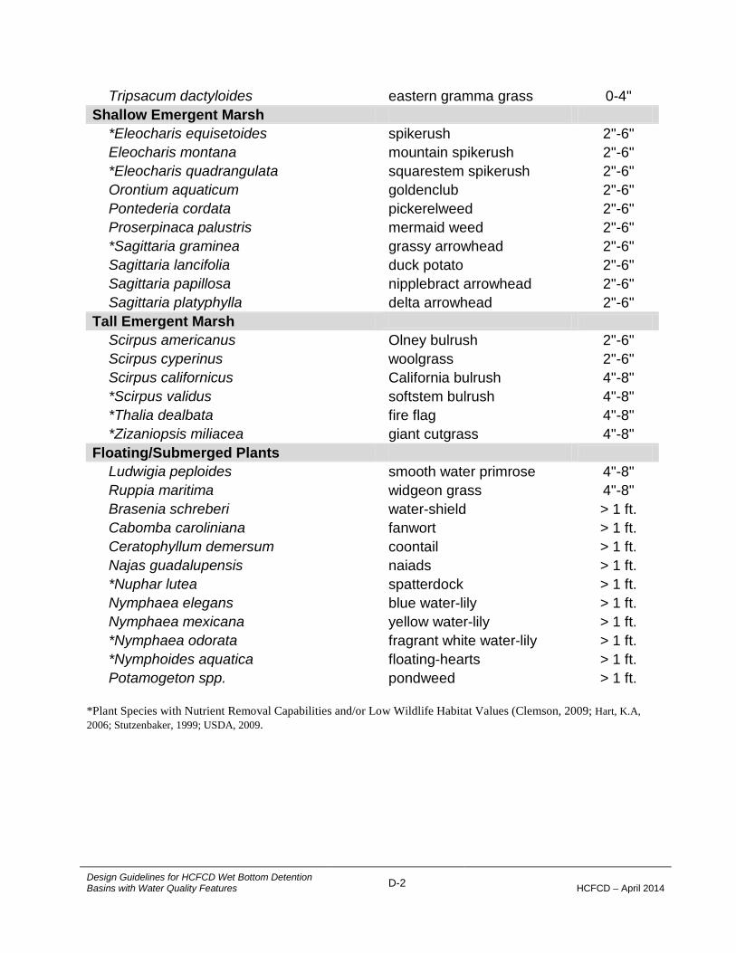
Design Guidelines for HCFCD Wet Bottom Detention Basins with Water Quality Features
D-2 HCFCD – April 2014
Tripsacum dactyloides eastern gramma grass 0-4"
Shallow Emergent Marsh
*Eleocharis equisetoides spikerush 2"-6"
Eleocharis montana mountain spikerush 2"-6"
*Eleocharis quadrangulata squarestem spikerush 2"-6"
Orontium aquaticum goldenclub 2"-6"
Pontederia cordata pickerelweed 2"-6"
Proserpinaca palustris mermaid weed 2"-6"
*Sagittaria graminea grassy arrowhead 2"-6"
Sagittaria lancifolia duck potato 2"-6"
Sagittaria papillosa nipplebract arrowhead 2"-6"
Sagittaria platyphylla delta arrowhead 2"-6"
Tall Emergent Marsh
Scirpus americanus Olney bulrush 2"-6"
Scirpus cyperinus woolgrass 2"-6"
Scirpus californicus California bulrush 4"-8"
*Scirpus validus softstem bulrush 4"-8"
*Thalia dealbata fire flag 4"-8"
*Zizaniopsis miliacea giant cutgrass 4"-8"
Floating/Submerged Plants
Ludwigia peploides smooth water primrose 4"-8"
Ruppia maritima widgeon grass 4"-8"
Brasenia schreberi water-shield > 1 ft.
Cabomba caroliniana fanwort > 1 ft.
Ceratophyllum demersum coontail > 1 ft.
Najas guadalupensis naiads > 1 ft.
*Nuphar lutea spatterdock > 1 ft.
Nymphaea elegans blue water-lily > 1 ft.
Nymphaea mexicana yellow water-lily > 1 ft.
*Nymphaea odorata fragrant white water-lily > 1 ft.
*Nymphoides aquatica floating-hearts > 1 ft.
Potamogeton spp. pondweed > 1 ft.
*Plant Species with Nutrient Removal Capabilities and/or Low Wildlife Habitat Values (Clemson, 2009; Hart, K.A, 2006; Stutzenbaker, 1999; USDA, 2009.

Design Guidelines for HCFCD Wet Bottom Detention Basins with Water Quality Features
D-3 HCFCD – April 2014
Appendix D2 – HCFCD Woody Plant Species
Large Trees Slope Zone Wetland
Hydric
Taxodium distichum bald cypress 1 to 2 OBL Acer rubrum var. drummondii swamp red maple 2 FAC Gleditsia aquatica water honey locust 2 OBL Nyssa aquatica water tupelo 2 OBL Carya aquatica water hickory 2 OBL Betula nigra river birch 2 to 3 FACW Gleditsia triacanthos honey locust 2 to3 FAC Fraxinus americana white ash 2 to 3 FACU Fraxinus pennsylvanica green ash 2 to 3 FACW Quercus lyrata overcup oak 2 to 3 OBL Quercus michauxii swamp chestnut oak 2 to 3 FAC Celtis laevigata sugarberry 2 to 4 FACW Liquidambar styraciflua sweetgum 2 to 4 FAC Platanus occidentalis American sycamore 2 to 4 FACW Ulmus americana American elm 2 to 4 FAC Ulums crassifolia cedar elm 2 to 4 FAC Juglans nigra black walnut 2 to 4 UPL Quercus falcata southern red oak 2 to 4 FACU Mesic
Quercus nigra water oak 3 FAC Quercus texana Nuttall oak 3 FACW Quercus phellos willow oak 3 FACW Quercus shumardii Shumard oak 3 FAC Carya illinoinensis pecan 3 to 4 FACU Quercus alba white oak 3 to 4 FACU Quercus macrocarpa bur oak 3 to 4 FACU Xeric
Magnolia grandiflora southern magnolia 4 FAC Pinus taeda loblolly pine 4 FAC Quercus muehlenbergii chinquapin oak 4 UPL Quercus virginana live oak 4 FACU Magnolia grandiflora southern magnolia 4 FAC

Design Guidelines for HCFCD Wet Bottom Detention Basins with Water Quality Features
D-4 HCFCD – April 2014
Appendix D2 – HCFCD Woody Plant Species
Small Trees/Shrubs/Vines Slope Zone Wetland
Hydric Cephalanthus occidentalis buttonbush 1 to 2 OBL
Forestiera acuminata swamp privet 2 OBL Ilex decidua possumhaw 2 FACW Sabal minor dwarf palmetto 2 FACW Itea virginica Virginia sweetspire 2 to 3 FACW Viburnum dentatum arrowwood 2 to 3 FACU Mesic Callicarpa americana American beautyberry 3 FACU Carpinus caroliniana ironwood 3 FAC Chionanthus virginicus white fringe tree 3 FACU Crataegus marshallii parsley hawthorne 3 FAC Crataegus opaca mahaw 3 OBL Diospyros virginiana persimmon 3 NI Halesia diptera two-wing silverbell 3 FAC llex opaca American holly 3 FAC Malvaviscus arboreus turk's cap 3 FAC Morus rubra red mulberry 3 FACU Prunus mexicana Mexican plum 3 NI Virbrunum rufidulum rusty blackhaw 3 UPL Cercis canadensis redbud 3 to 4 NI llex vomitoria yaupon 3 to 4 FAC Juniperus virginiana eastern red cedar 3 to 4 FACU Morella cerifera wax myrtle 3 to 4 FAC Prunus caroliniana cherry laurel 3 to 4 FACU Rhus lanceolata flame leaf sumac NI Asimina triloba paw paw FACU
Vines Bignonia capreolata cross vine 3 FAC
Campsis radicans trumpet creeper 3 FAC Passiflora incarnata passion-flower 3 NI Passiflora lutea yellow passion-flower 3 NI

Design Guidelines for HCFCD Wet Bottom Detention Basins with Water Quality Features
D-5 HCFCD – April 2014
Appendix D3 – Projected Tree Displacement
DBH*/Year (min)
DBH/Year (max)
30 Year DBH in. (max)**
Basal Area *** 30-Year max
(sq. ft.) Large Trees 0.4 0.5 15 1.227
Small Trees
6 0.196 Redbud
10 0.545
Cherry Laurel
12 0.785
# Trees /
acre
Basal Area 30-Year max (sq. ft./acre)†
75% Large Trees 331
405.686 20% Small Trees 88
17.309
2.5% Redbud 11
6.010 2.5% Cherry Laurel 11
8.655
TOTAL 437.660
1.005
TOTAL % displacement
* Growth rates were estimated using input from Texas Forest Service staff. These are rough figures based on general growth rates for the region. ** DBH = Diameter at Breast Height (4.5 feet above ground surface) *** Basal Area refers to the cross-sectional area taken up by the trunks and stems † Assume tree spacing of 10 ft. on center – 441 trees per acre.

Design Guidelines for HCFCD Wet Bottom Detention Basins with Water Quality Features
HCFCD – April 2014
This page intentionally left blank

Design Guidelines for HCFCD Wet Bottom Detention Basins with Water Quality Features
HCFCD – April 2014
Appendix E
Standards and Details
E1 – Vegetated Rip-Rap Grade Control Berm E2 – Water Quality Instrument Holder & Staff Guage

Design Guidelines for HCFCD Wet Bottom Detention Basins with Water Quality Features
HCFCD – April 2014
This page intentionally left blank

DESIGN GUIDELINES FOR HCFCDWET BOTTOM DETENTIONBASINS WITH WATERQUALITY FEATURES
VEGETATED RIPRAP GRADE CONTROL BERM
DATE 04/15/2014 APPENDIX E1
TYPI
CAL
RIPR
AP G
RADE
CO
NTR
OL
BERM
BERM
UPP
ERPE
RMAN
ENT
POO
LLO
WER
PERM
ANEN
T PO
OL
RIP-
RAP
TOP
OF
BERM
2’ M
IN
6” to 12”
3’ M
IN
18” MIN
1’ to 3’
VEGE
TATE
D SH
ELF
12”
DEEP
BU
RIED
RIP
-RAP
4:14:1

Design Guidelines for HCFCD Wet Bottom Detention Basins with Water Quality Features
HCFCD – April 2014
This page intentionally left blank


Design Guidelines for HCFCD Wet Bottom Detention Basins with Water Quality Features
HCFCD – April 2014
This page intentionally left blank

Design Guidelines for HCFCD Wet Bottom Detention Basins with Water Quality Features
HCFCD – April 2014
Appendix F
References and Resources

Design Guidelines for HCFCD Wet Bottom Detention Basins with Water Quality Features
HCFCD – April 2014
This page intentionally left blank

Design Guidelines for HCFCD Wet Bottom Detention Basins with Water Quality Features
HCFCD – April 2014
References Clemson, 2009. Aquatic Plant Profiles, Clemson University Cooperative Extension Service, Clemson University, Clemson, South Carolina. http://www.clemson.edu/extension/horticulture/nursery/constructed_wetlands/plant_material/index.html
EPA, 1999a. Stormwater Technology Fact Sheet, Wet Detention Ponds, EPA-832-F-99-048, U.S. Environmental Protection Agency, Office of Water, Washington D.C., September 1999.
EPA, 1999b. Preliminary Data Summary of Urban Storm Water Best Management Practices, EPA-821-R-99-012, U.S. Environmental Protection Agency, Office of Water, Washington D.C., August 1999.
EPA, 2000. Constructed Wetlands Treatment of Municipal Wastewaters, EPA-625-R-99-010, and U.S. Environmental Protection Agency, Office of Research and Development, Cincinnati, Ohio, 45268, September 2000.
EPA, 2009. Stormwater Wet Pond and Wetland Management Guidebook. EPA 833-B-09-001, U.S. Environmental Protection Agency, February 2009.
Hart, K.A, 2006. Evaluation of the Nutrient Removal Efficiency of a Constructed Wetland System, Texas A&M University, Electronic Thesis and Dissertation Collection, College Station, Texas; August. http://repository.tamu.edu/handle/1969.1/4293
HCFCD, 1985. Barker Reservoir Watershed Sedimentation Study. Prepared by Winslow & Associates, Inc. and McClelland Engineers. February 1985.
HCFCD, 2005. HCFCD 2005 Standard Specifications Book, Harris County Flood Control District, Houston, TX, August 2005.
HCFCD, 2007. Policy White Paper; Incorporating Water Quality in Future Flood Damage Reduction Facilities. September 21, 2007.
HCFCD, 2008. Storm Water Quality Pond Monitoring Protocol Revised, Version 2.0, May 2008. Prepared by PBS&J.
HCFCD, 2010a. HCFCD Engineering and Construction Division Reference Guide. Version 3.0. May 2010.
HCFCD, 2010b. Storm Water Management Program. TPDES Permit No. WQ0004685000, Revised October 31, 2010.

Design Guidelines for HCFCD Wet Bottom Detention Basins with Water Quality Features
HCFCD – April 2014
References, Continued
HCFCD, 2010c. HCFCD Policy, Criteria, and Procedure Manual for Approval and Acceptance of Infrastructure, Harris County Flood Control District, Houston, Texas, Adopted October 2004, Updated December 2010.
HCFCD, 2011. HCFCD Water Quality (WQ) Opportunity Planning Tool. Prepared by Atkins, July 2011.
HCFCD, 2012. HCFCD Water Quality Enhancement Section Requirements for a Preliminary Engineering Report (PER) or Project Design Report (PDR). April 2012.
JTF, 2001a. Storm Water Quality Management Guidance Manual, Storm Water Management Joint Task Force (JTF) comprising City of Houston, Harris County, Harris County Flood Control District, and Texas Department of Transportation (2001).
JTF, 2001b. Minimum Design Criteria for Implementation of Certain Best Management Practices for Storm Water Runoff Treatment Options, Storm Water Management Joint Task Force (JTF) comprising City of Houston, Harris County, Harris County Flood Control District, and Texas Department of Transportation (2001).
Southern California Coastal Water Research Project (SCCWRP), 2007. Sources, Patterns and Mechanisms of Storm Water Pollutant Loading From Watersheds and Land Uses of the Greater Los Angeles Area, California, USA. Technical Report 510, March 20, 2007.
Schueler, T., 1987. Controlling Urban Runoff: A Practical Manual for Planning and Designing Urban Best Management Practices. Metropolitan Washington Council of Governments. Washington, D.C.
Stutzenbaker, 1999. Aquatic and Wetland Plants of the Western Gulf Coast, Texas Parks and Wildlife, Wildlife Division, Austin, Texas.
TCEQ, 2008. TPDES General Permit Number TXR150000 Relating to Storm Water Discharges Associated with Construction Activities. Storm Water Program, February 15, 2008.
TCEQ, 2009. Procedures to Implement the Texas Surface Water Quality Standards. Prepared by the Water Quality Division, RG-194, December 2009.
Turner Collie and Bradon (TCB), 2006. Wet Pond Sedimentation Survey and Design Criteria Evaluation for Harris County, Prepared for Harris County Stormwater Quality Section, June 2006.
USDA, 1976. Soil Survey of Harris County, Texas, U.S. Department of Agriculture Soil Conservation Service in Cooperation with Texas Agricultural Experiment Station and Harris County Flood Control District, August 1976.

Design Guidelines for HCFCD Wet Bottom Detention Basins with Water Quality Features
HCFCD – April 2014
References, Continued USDA, 2009. Plants Profile, United States Department of Agriculture Natural Resources Conservation Service, Plants Database. http://plants.usda.gov
Weston, 2002. Data Collection and Review Guidelines for Siting and Preliminary Engineering of Stormwater Quality Pond Systems in Harris County, Weston Solutions, Houston, Texas, 77056, June 2002.

Design Guidelines for HCFCD Wet Bottom Detention Basins with Water Quality Features
HCFCD – April 2014
Resources North Carolina State Cooperative Extension, Urban Waterways Fact Sheets: Maintenance of Stormwater Wetlands and Wet Ponds http://www.bae.ncsu.edu/stormwater/PublicationFiles/WetlandMaintenance2006.pdf
Removal of Pathogens in Stormwater http://www.bae.ncsu.edu/stormwater/PublicationFiles/PathogensSW.2008.pdf
Stormwater Wetland Design http://www.bae.ncsu.edu/stormwater/PublicationFiles/WetlandDesignUpdate2007.pdf Mosquito Control for Stormwater Facilities http://www.bae.ncsu.edu/stormwater/PublicationFiles/Mosquitoes2005.pdf Designing Stormwater Wetlands for Small Watersheds http://www.bae.ncsu.edu/stormwater/PublicationFiles/SWwetlands2000.pdf Urban Stormwater Structural Best Management Practices (BMPs) http://www.bae.ncsu.edu/stormwater/PublicationFiles/UrbanBMPs1999.pdf Evapotranspiration (ET) rates for Houston, Texas http://texaset.tamu.edu/index.php Evaporation Data for Texas http://midgewater.twdb.state.tx.us/Evaporation/evap.html