this specification data sheet brought to you by
TRANSCRIPT

The attached material is copyrighted by and will remain the property of the individual manufacturers. Technical Diagnostic Services is providing this information at no charge as a service to our customers.
This Specification Data Sheet brought to you by:
15825 Trinity Blvd.
Fort Worth, Texas 76155 817/465-9494
www.technicaldiagnostic.com www.test-equipment-rental.com
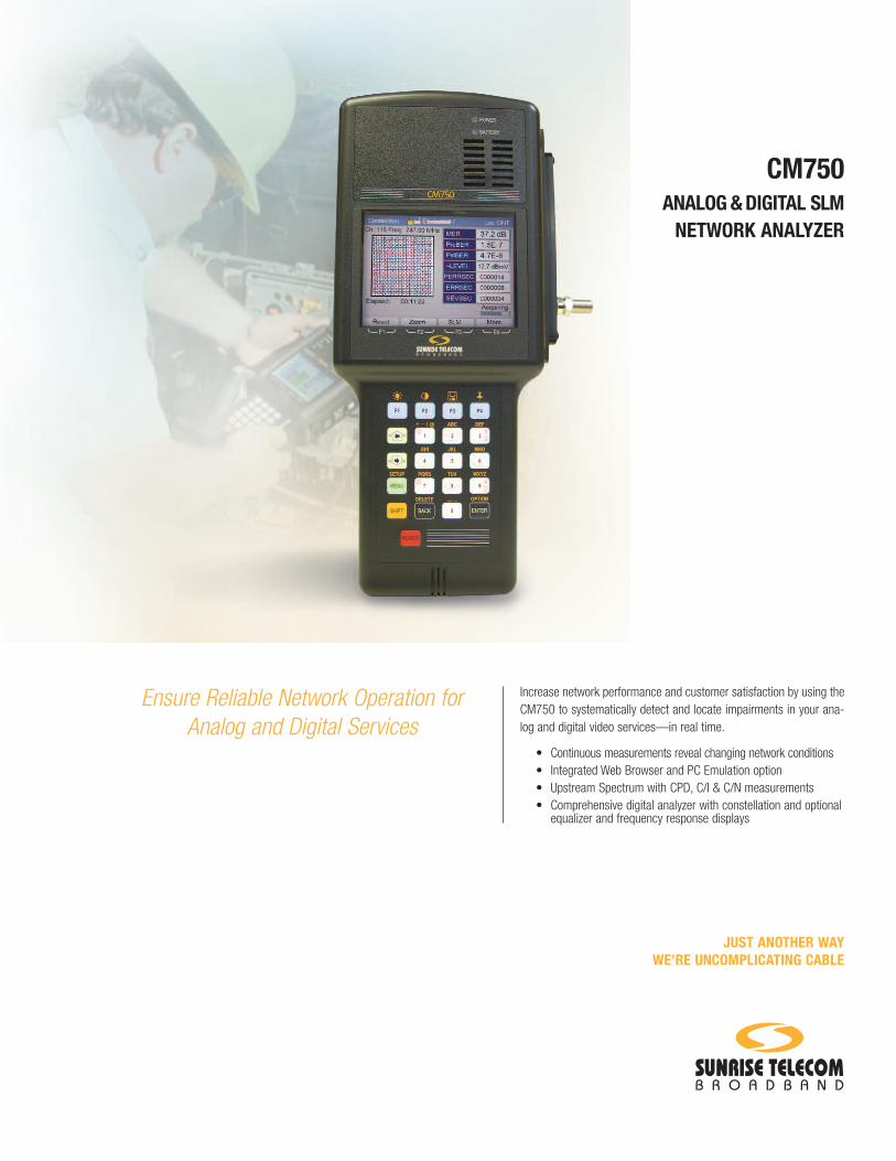
Increase network performance and customer satisfaction by using theCM750 to systematically detect and locate impairments in your ana-log and digital video services—in real time.
• Continuous measurements reveal changing network conditions• Integrated Web Browser and PC Emulation option• Upstream Spectrum with CPD, C/I & C/N measurements• Comprehensive digital analyzer with constellation and optional
equalizer and frequency response displays
JUST ANOTHER WAYWE’RE UNCOMPLICATING CABLE
CM750ANALOG & DIGITAL SLM
NETWORK ANALYZER
Ensure Reliable Network Operation forAnalog and Digital Services

2
OVERVIEW
…it’s ready to work whenever and wherever your technicians need it.
Full analog and digital SLM functions make the CM750 the most compre-hensive troubleshooting tool available.
Easy-to-use pass/fail test screens indicate problems quickly, so thatadjustments, replacements and follow-up verification tests can be per-formed immediately. The CM750’s in-band capabilities and continuousmeasurements simplify locating tough intermittent problems.
The CM750’s rugged construction makes it ready to work whenever andwherever your technicians need it—no need to leave the meter turned onbetween uses, boot up time is less than 30 seconds. The integrated fanventilation allows continuous meter operation. The CM750 will operatecontinuously at up to 120°F ambient and can be used even in the heav-iest rain. And when the sun is shining the improved LCD screen affordsgreat screen visibility.
Test anywhere in the network—even use the CM750’s optionalBrowser function to substitute for the customer’s PC to troubleshoot in-home wiring, routers, firewalls and hubs. Lighten your workforce’s loadwith the CM750—it’s more versatile and easier to carry than a meterand a laptop for field testing. The Web Browser option can allow yourtechnicians to be more efficient by providing access to your workforcemanagement system.
The CM750 provides quick, reliable and repeatable results from man-ual or automated testing that can be stored or uploaded to a PC or toa server over the network for analysis or integration into back officemanagement systems.

3
…the one-meter solution for North America and worldwide.
CM750 SLMAccurately measure the level of all common modulated carriers.
• Full analog and digital measurements• 1 channel and Scan channel display• C/N Measurement (off channel)• Auto scan with user programmable pass/fail limits• System tilt, peak-to-valley, and adjacent channel measurements• Detail screens with all measurement results or view just the
results outside the pass/fail limits
Users may select Single Channel or Scan SLM modes to view a varietyof channels. Single Channel mode provides an analog and digital read-out of the channel’s level with results outside the pass/fail criteria dis-played in red. Analog channels display the video carrier, audio carrier,carrier to noise ratio and adjacent channel’s levels. Digital channels dis-play the Average Power Level of the QAM signal and the adjacent chan-nel’s level. Scan SLM mode provides a display of the entire channel planincluding video and audio carriers and digital signals. It also displayssummaries of the measurements, including analog and digital results forminimum and maximum level, tilt and Peak-to-Valley. In addition, worstcase video-to-audio ratio, worst case adjacent channel ratio and theaverage analog to digital power ratio measurements are provided. Detailscreens allow views of all of the measurement results or are limited toresults outside of the programmed limits criteria.
The CM750 provides complete measurement detail for the selected chan-nel and automatically switches between analog and digital operation.
The CM750 provides NTSC and PAL-M analog and Annex B and C dig-ital video analysis for North American and other networks compatiblewith a 6 MHz channel spacing.
SLM Analog Display
INTEGRATEDANALOG & DIGITAL SLM
SLM Digital Display

4
The CM750 includes SMART tests. The administrator programmable tests are usedto automatically evaluate network performance and to provide consistent and com-prehensive testing. All test results can be saved and uploaded over the network.SMART test setups and instrument configurations can be stored on the networkand downloaded to any meter when needed, making configuration changes easyand ensuring consistent testing.
Three SMART test locations are provided, each with its own set of programmabletests and pass/fail limits. SMART tests may include analog and digital level scans(with custom channel plans), digital MER and BER. These one-button tests are agreat way to quickly and consistently run a series of tests to ensure that the net-work is meeting performance requirements and has sufficient safety margins tokeep running.
View Simple pass/fail test results, summary screens or complete test details. Drilldown into the details as much as necessary or as little as desired.
Summary graphs provide the range of test results and the acceptable passingrange on a single easy-to-interpret bar graph. Or view the numeric version of thesame data for exact measurement results.
Also drill down to the detail for all measurement data or view just those results thatare outside of the measurement limits.
“SMART”ONE-BUTTON TESTS
…easily run comprehensive tests, quickly and consistently.
COMPREHENSIVE TESTS
DOWNSTREAM:• Analog Signal Level• Digital Signal Level• Channel Scan• MER, BER, Constellation• Downstream Spectrum Analyzer with CC/N• Optional Equalizer and Frequency Response and Auto Diagnosis
UPSTREAM:• Spectrum Display with C/N and C/I
NETWORK/PC:• Substitute emulate PC• Verify the PC DHCP process• Optional Web Browser
…comprehensive tests assist the technician in systematicallyidentifying and correcting the cause of a failure.

5
…constellation display eliminates the guesswork.
Display the QAM modulated signal and use the CM750 to identifydownstream impairments. Quickly diagnosis and reliably identifyimpairments such as noise, interference, phase noise, CSO, in-bandspurs, laser clipping, and gain problems. Optional Equalizer Stress andFrequency Response screens may be added for complete downstreamtroubleshooting.
MERModulation error ratio provides early detection of non-transient, digitalimpairments including system noise, CSO, CTB, ingress and modula-tor problems. The CM750’s pass/fail display allows technicians toquickly detect if MER meets recommended system levels for 64 QAMor 256 QAM signals. As the number of subscribers increases, ensur-ing adequate MER becomes more critical than ever. Poor MER canresult in degraded performance, due to excessive packet retransmis-sions, and resultant customer dissatisfaction. Never risk falling over“the digital cliff;” the CM750 helps you make sure that you have a safeoperating margin.
PRE- AND POST-FEC BIT ERROR RATE (BER)The CM750’s BER display is especially useful for tracking down tran-sient problems such as intermittent ingress, node non-linearity andlaser clipping. Verify the occurrence of downstream errors with thepre-forward error correction bit error rate (PreBER). Determine if theFEC function is successfully working with the post-FEC BER (PstBER).The display indicates errored seconds for pre- and post-FEC correc-tion. If the errors are not correctable, a Severely Errored Second is dis-played—an indicator of poor network performance.
DEEP INTERLEAVESome digital video modulators utilize a deep interleave on 256 QAMmodulation. The Deep Interleave feature allows the CM750 to make BERmeasurements on deep interleave (i=4, j=128) digital video signals.
For more information on QAM constellations, MER and BER, go to ouronline CATV Training page at www.sunrisetelecom.com.
Downstream Screen with Constellation Display
DOWNSTREAMTROUBLESHOOTING
Downstream Screenwith Equalizer Display (Optional)
Downstream Screen with FrequencyResponse Display (Optional)
…technicians can detect isolate and repair networkissues long before they affect your customers.

6
…ensure the optimum transmit level, assure an appropriate safety margin, andoptimize the path attenuation for maximum ingress reduction.
Eliminate slow uploads due to return path ingress, noise and CPD. TheUpstream Spectrum feature offers the simplest automated method fortesting and troubleshooting the return path. Use the CM750 to mea-sure bursty TDMA return signals, intermittent ingress, noise and CPD(common path distortion). Simply set the markers and the CM750does all the work, reading out the carrier level of TDMA signals, CPDor ingress, C/I ratio and C/N ratio.
Your technicians know the return path is often the most demandingportion of the network. Let the CM750 simplify their job with the sim-plest, automated return path test and troubleshooting process in thefield. Set the markers and let the CM750 provide a simple pass/failindication or use it to troubleshoot any portion of the return path.
An Ingress screen displays the ingress level, noise level and marginbetween these and the programmed pass/fail limits. Markers are pre-programmed, but may be repositioned by the user.
UPSTREAMSPECTRUM
Upstream Spectrum Display
The downstream Spectrum Analyzer provides a spectral view of any64, 32, 16 or 8 MHz span in the 50 to 870 MHz range. View signal,Ingress or Distortions on the network and use the markers to measureanalog or digital signals, CC/N (carrier to noise) or C/I (carrier toingress). Setup allows the user to select the peak detector for analogsignals or select the average detector and set the occupied bandwidthfor accurate digital level measurements.
DOWNSTREAMSPECTRUM
Downstream Spectrum Display

7
CM-WB WEB BROWSER Use the web browser and PC emulation option to test in-home RFand Ethernet wiring, routers, PCs or other components. Demonstratenetwork operation by accessing external web sites. The web brows-er may also be used to access employee email or workforce man-agement applications via the network. Use the browser for set-topand cable modem provisioning or to view the modem’s diagnosticpage. Administrator controls allow unlimited browsing or access tospecified URLs only.
Keep all your meters up-to-date quickly and easily. Download con-figurations files and even firmware upgrades over your network viathe Ethernet port. Select any configuration file to completely setevery programmable configuration in your meter. No need to bring ameter back to the office or service center for firmware updates, justdownload the firmware and install it right in the field—no PC orother tools required.
EXTENDED DIGITAL MEASUREMENTS OPTIONCM-DIG Extended Digital Measurements includes the AdaptiveEqualizer display and Frequency Response display in the SLM mode forDigital Measurements. See Downstream Troubleshooting for details.
FIRMWARE OPTIONS
Easily download and install firmware upgrades
Flexibility…upgrade your CM750 with firmware options right in the field.
8
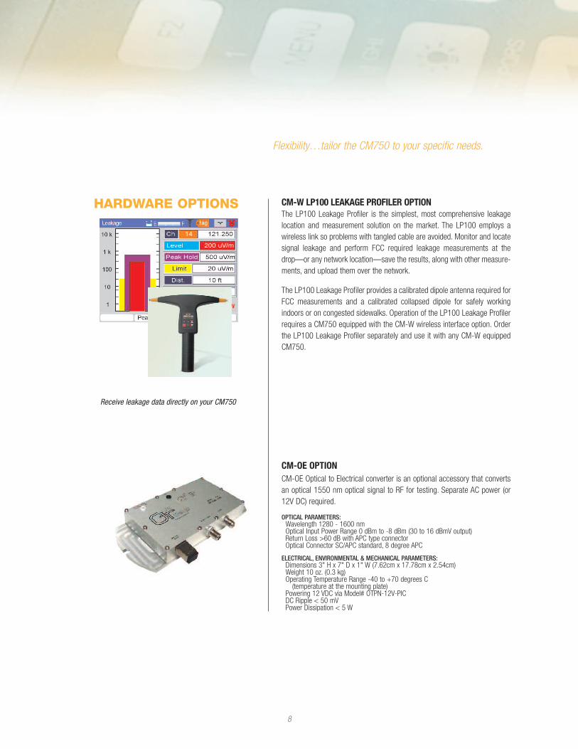
CM-W LP100 LEAKAGE PROFILER OPTIONThe LP100 Leakage Profiler is the simplest, most comprehensive leakagelocation and measurement solution on the market. The LP100 employs awireless link so problems with tangled cable are avoided. Monitor and locatesignal leakage and perform FCC required leakage measurements at thedrop—or any network location—save the results, along with other measure-ments, and upload them over the network.
The LP100 Leakage Profiler provides a calibrated dipole antenna required forFCC measurements and a calibrated collapsed dipole for safely workingindoors or on congested sidewalks. Operation of the LP100 Leakage Profilerrequires a CM750 equipped with the CM-W wireless interface option. Orderthe LP100 Leakage Profiler separately and use it with any CM-W equippedCM750.
CM-OE OPTIONCM-OE Optical to Electrical converter is an optional accessory that convertsan optical 1550 nm optical signal to RF for testing. Separate AC power (or12V DC) required.
OPTICAL PARAMETERS:Wavelength 1280 - 1600 nmOptical Input Power Range 0 dBm to -8 dBm (30 to 16 dBmV output)Return Loss >60 dB with APC type connectorOptical Connector SC/APC standard, 8 degree APC
ELECTRICAL, ENVIRONMENTAL & MECHANICAL PARAMETERS:Dimensions 3" H x 7" D x 1" W (7.62cm x 17.78cm x 2.54cm)Weight 10 oz. (0.3 kg)Operating Temperature Range -40 to +70 degrees C
(temperature at the mounting plate)Powering 12 VDC via Model# OTPN-12V-PICDC Ripple < 50 mVPower Dissipation < 5 W
HARDWARE OPTIONS
Flexibility…tailor the CM750 to your specific needs.
Receive leakage data directly on your CM750
9
DIGITAL SIGNAL ANALYSISModulation Type Downstream:
64/256 QAM (DVS- 031, ITU-T J.83 Annex B Lock Range 64 QAM: -15 to +60 dBmV (typical)Lock Range 256 QAM: -10 to +60 dBmV (typical)Downstream Modulation Error Ratio (MER):
Range: 21 to 40 dB Accuracy: ±1.0 dB (typical)
DIGITAL SIGNAL LEVEL METERAccuracy: ±1.0 dB @ 25°C (typical)Frequency Range: 5–860 MHz
GRAPHIC DISPLAYSConstellation: I-Q display of 64 or 256 QAM signalBit Error RateDownstream BER Range: 1.0 x 10⁻⁹ to 9.0 x 10⁻³Errored Seconds: Numerical count of downstream errored sec-
ondsDownstream FEC Lock: Loss/Lock-indicationSeverely Errored Seconds: Numerical count of downstream
severely errored secondsElapsed Time: hr, min, secUpstream BkER: BkER, Lost Packet Count and PING time
PLUG-IN INTERFACES10/100Base-T Ethernet75 ohm F81 (field replaceable)RS232, PC interface port
POWERPower: Internal NiMH battery packOperating Time: 3 hours continuous (typical)External Power: 120/240 VAC Adapter/Charger12 VDC vehicle chargerPower Reduction: Auto unit shut down
GENERALDisplay: Reflective color active matrix LCD 320 x 240 viewable in
full sunOperating Temperature Range: -10º–50ºC
Specifications subject to change without notice.
CM750 SPECIFICATIONS
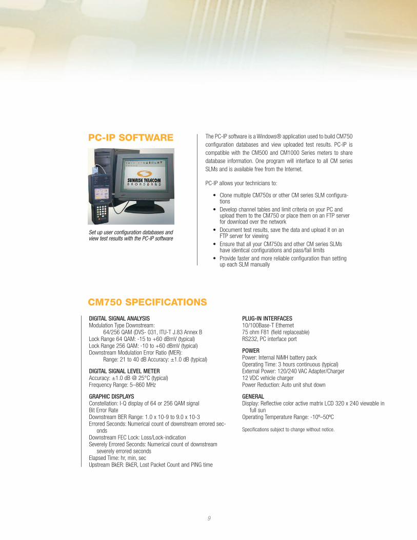
The PC-IP software is a Windows® application used to build CM750configuration databases and view uploaded test results. PC-IP iscompatible with the CM500 and CM1000 Series meters to sharedatabase information. One program will interface to all CM seriesSLMs and is available free from the Internet.
PC-IP allows your technicians to:
• Clone multiple CM750s or other CM series SLM configura-tions
• Develop channel tables and limit criteria on your PC andupload them to the CM750 or place them on an FTP serverfor download over the network
• Document test results, save the data and upload it on anFTP server for viewing
• Ensure that all your CM750s and other CM series SLMshave identical configurations and pass/fail limits
• Provide faster and more reliable configuration than settingup each SLM manually
PC-IP SOFTWARE
Set up user configuration databases andview test results with the PC-IP software

10
ORDERING INFORMATION
CM750Includes:
Analog & Digital SLM with tuning range: 50-860 MHz, Annex B &C, RF Input F81 75 ohm connector (field replaceable), Serialinterface EIA RS-232, Ethernet modem/PC interface, 100-240Vbattery charger, Quick Start Guide, User’s Manual, and DigitalTraining CD, CE certified.
INCLUDED ACCESSORIES:PC-IP software, rubber boot, bag, strand hook, RS-232 cable,100 to 240 V AC charger, manual, training CD-ROM and 12-voltvehicle charger
FIRMWARE OPTIONSCM-WB Web BrowserCM-DIG Extended Digital Analysis including Equalizer Stress
and Frequency Response displays
HARDWARE OPTIONSCM-W Wireless interface for leakage detection (LP100
required)CM-DVM Deep Interleave (4, 128 digital video) Digital Video BER
MeasurementsCM-OE Optical to Electrical node for converting optical to RF
signals. Separate power supply and optical jumperincluded.
JUST ANOTHER WAY WE’RE UNCOMPLICATING CABLE
FIELD-PROVEN SOLUTIONSFor detailed information on the CM750 and its options or the name of yourlocal Sunrise representative visit our website at www.sunrisetelecom.com.Or telephone us at 1-800-297-9726 (International calls: 1-514-725-6652).
Sunrise Telecom Broadband is a leader in digital broadband and DOCSIStest instruments for the broadband industry. As part of the Sunrise Telecomfamily, we leverage the strength of one of the world’s largest test and mea-surement companies to make your job easier. Sunrise TelecomBroadband’s field-proven solutions include installation and maintenanceinstruments, portable headend analyzers and network test systems andsoftware. Our goal is to enable service providers to rapidly deploy televi-sion, high-speed Internet, voice and digital video applications.
Based on our core strength in RF testing, we have established a success-ful track record as a provider of leading edge solutions that incorporateinnovative test methods, intuitive user interfaces, and thorough producttraining. At Sunrise Telecom Broadband, we uncomplicate the engineer’sand field technician’s day.
© Sunrise Telecom Broadband. All rights reserved. 060124
U.S. OfficeSunrise Telecom Broadband, Inc.3250-D Peachtree Corners CircleNorcross, GA U.S.A. 30092
Canada & International OfficeSunrise Telecom Broadband Corp.10281 Renaude-LapointeAnjou, QC Canada H1J 2T4
North American Toll-Free:1-800-297-9726International1-514-725-6652
Corporate Head OfficeSunrise Telecom302 Enzo Drive San Jose, CA 95138 U.S.A.1-408-363-8000Fax: 1-408-363-8313