thor intrusion system - asset id · technical manual thor intrusion system 91000601 program version...
TRANSCRIPT

Technical Manual
Thor Intrusion System
91000601
Program version number: EU1-078.0609.030EU2-078.0609.030
Publication date: 030214

91000601
Revision history:
Ref. No. Revision remarks Date
92001001 First version 010518
92001001 Compliance information added to preface.Section about ferrite clamps added to Chapter 2.
030214
91000601
TechnicalTechnicalTechnicalTechnicalManualManualManualManual
Thor Intrusion SystemThor Intrusion SystemThor Intrusion SystemThor Intrusion SystemThis manual provides an overview of the Thor Intrusion systems, the concept ofS-ART technology, concepts, input and output facilities and the way ofoperation.The manual also includes detailed description of the various componentsincluding information about their installation and connection.Needed programming information can also be found in this manual together witha description of the operation of the systems.
The manual is valid from the date of publication stated below.
Due to continuous research and development, the information contained in thisdocument is subject to change without notice.
HI SEC International declines any liability for not respecting or incorrectly usingthe information in this manual, as well as errors or omissions and theirconsequences in the installations.
The date of publication is 030214.
EU1-078.0609.030 and EU2-078.0609.030
Reference number: 91000601.
Disclaimer
Date
Version
Reference

91000601
If the installation instructions supplied in this manual are followed, the ThorIntrusion System complies with the following standards:
EN 50130-4 Alarm systemsPart 4: Electromagnetic compatibility. Product family standard:Immunity requirements for components of fire, intruder and socialalarm systems.
EN 50082-1 Generic Immunity StandardPart 1: Residential, commercial and light industry.
EN50082-2 Generic Immunity StandardPart 2: Industrial environment, heavy industry.
EN 50081-1 Electromagnetic compatibility - Generic emission standardPart 1: Residential, commercial and light industry.
EN 60950 Safety of information technology equipment, including electricalbusiness equipment.
Copyright © 2003 by HI SEC International. All rights reserved. No part of thismanual may be reproduced or transmitted in any form for any purpose withoutthe written permission of HI SEC International.
In our continuous effort to improve the documentation for our products, we needfeedback from our users regarding useability, appearance, technical level ofcontent as well as information about errrors you may find.
You can mail your comment and corrections to the address: [email protected]
Compliance
EMC immunity
EMC emission
Safety
Copyright
Comments andcorrections

91000601
Table of contents1. Functional description ................................................................... 1-1
1.1 General description ........................................................................... 1-21.1.1 Local site intrusion system ................................................................ 1-21.1.2 Remote site intrusion system ............................................................ 1-31.1.3 System part list.................................................................................. 1-4
1.2 System description............................................................................ 1-8
1.3 S-ARTs............................................................................................ 1-101.3.1 System diagram .............................................................................. 1-101.3.2 Line signals ..................................................................................... 1-10
1.4 The logical area concept ................................................................. 1-12
1.5 Inputs............................................................................................... 1-141.5.1 Overview of input soft types ............................................................ 1-141.5.2 Input soft type description ............................................................... 1-151.5.3 Input addresses and standard programming .................................. 1-22
1.6 Outputs............................................................................................ 1-261.6.1 Overview output soft types .............................................................. 1-261.6.2 Output soft type description............................................................. 1-281.6.3 Output addresses and standard programming ............................... 1-32
1.7 Reaction tables................................................................................ 1-341.7.1 Reaction table – local alarm/fault outputs ....................................... 1-341.7.2 Reaction table – transmission outputs ............................................ 1-351.7.3 Reaction table – various outputs ..................................................... 1-36
1.8 Timers and timer functions.............................................................. 1-371.8.1 Timer duration functions and delay functions.................................. 1-371.8.2 Output soft types and software timer types..................................... 1-38
1.9 Alarm functions ............................................................................... 1-411.9.1 IF - THEN expressions.................................................................... 1-411.9.2 Alarm functions for local / transmission outputs.............................. 1-421.9.3 Auto alarm reset of output alarm functions ..................................... 1-421.9.4 Alarm function without alarm input condition................................... 1-421.9.5 Special operands............................................................................. 1-431.9.6 Standard input addresses ............................................................... 1-431.9.7 Standard output addresses ............................................................. 1-441.9.8 Special input addresses .................................................................. 1-44
1.10 Single-site and multi-subsite system............................................... 1-47
1.11 Auto alarm reset.............................................................................. 1-491.11.1 Input/output soft types affected by auto alarm reset ....................... 1-50
1.12 Anti-hostage system........................................................................ 1-511.12.1 Anti-hostage system operation........................................................ 1-521.12.2 Functional description ..................................................................... 1-53
2. Installation ...................................................................................... 2-1
2.1 Noise emmission prevention ............................................................. 2-2

91000601
2.2 90T CU-30 and 95T CU-30 central unit .............................................. 2-32.2.1 Lay-out of the 90T CU-30 central unit ............................................... 2-32.2.2 Lay-out of the 95T CU-30 central unit ............................................... 2-42.2.3 95T CUB-30 CPU board ................................................................... 2-52.2.4 Expansion board 95T I/O .................................................................. 2-92.2.5 Power supply and battery................................................................ 2-11
2.3 95T CU-30-24V Central unit ............................................................ 2-122.3.1 General information......................................................................... 2-122.3.2 Installation of the optional I/O-board ............................................... 2-132.3.3 Mounting.......................................................................................... 2-142.3.4 Connection to mains voltage........................................................... 2-152.3.5 Installation of backup batteries........................................................ 2-162.3.6 Connection terminals and jumpers ................................................. 2-17
2.4 S-ARTs units ................................................................................... 2-182.4.1 List of S-ART units .......................................................................... 2-182.4.2 S-ART housing................................................................................ 2-192.4.3 S-ART controller connections ......................................................... 2-202.4.4 S-ART detector connections ........................................................... 2-212.4.5 Coding of S-ART-addresses ........................................................... 2-35
2.5 Remote keypads ............................................................................. 2-372.5.1 Remote keypad 95T RKP ............................................................... 2-37
2.6 General purpose Interface 95T GPI COM ...................................... 2-392.6.1 PC Interface application .................................................................. 2-432.6.2 Modem/X28 Interface application.................................................... 2-442.6.3 SECOM transmitter interface application ........................................ 2-44
2.7 99T IPI TCP/IP interface ................................................................. 2-452.7.1 Factory mounted TCP/IP interfaces ................................................ 2-452.7.2 99T IPI TCP/IP interface as separate unit....................................... 2-462.7.3 99T IPI interface applications.......................................................... 2-462.7.4 99T IPI and 95T GPI XXX IP specifications.................................... 2-48
2.8 GPI BR Bridge................................................................................. 2-49
2.9 GPI BRM/DLM Direct line modem interface .......................................... 2-50
2.10 GPI DLC Bus amplifier .................................................................... 2-52
2.11 RS-485 bus connections ................................................................. 2-53
2.12 Cable length and dimension............................................................ 2-54
2.13 Current consumption....................................................................... 2-55
3. Programming .................................................................................. 3-1
3.1 General.............................................................................................. 3-2
3.2 Start-up procedures .......................................................................... 3-33.2.1 Start-up of a Thor Intrusion central unit............................................. 3-3
3.3 Programming of input addresses ...................................................... 3-5
3.4 Programming of output addresses.................................................... 3-6
3.5 Programming of zones, areas and codes........................................... 3-7
3.6 Programming of remote keypads to zones ............................................ 3-8
3.7 Auto set time programming............................................................... 3-93.7.1 Area week time programming ........................................................... 3-93.7.2 Holiday list ....................................................................................... 3-11

91000601
4. Operating instructions ................................................................... 4-1
4.1 Operating facilities.............................................................................. 4-2
4.2 Operation in general.......................................................................... 4-34.2.1 Daily operation .................................................................................. 4-34.2.2 Sub-menus...................................................................................... 4-104.2.3 Intrusion menus on the Card Reader .............................................. 4-114.2.4 Overview of the menus ................................................................... 4-124.2.5 Use of the function keys.................................................................. 4-134.2.6 Operator codes ............................................................................... 4-144.2.7 Code priority .................................................................................... 4-14
4.3 Submenu 2 - Display/change of status ............................................. 4-17
4.4 Submenu 3 - System test................................................................ 4-22
4.5 Submenu 4 - Programming............................................................. 4-26
4.6 Autoset programming....................................................................... 4-40

91000601
This page is intentionally left blank.

91000601 1-1
Functional descriptionFunctional descriptionFunctional descriptionFunctional descriptionThis chapter provides an overview of the Thor Intrusion System and theequipment available. It also describes the basic concepts of intrusion systemstogether with the functions (soft types) related to the inputs and outputs.
The chapter contains the following sections:
Section Page
General description 1-2
System description 1-8
S-ARTs 1-10
The logical area concept 1-12
Inputs 1-14
Outputs 1-26
Reaction tables 1-34
Alarm functions 1-41
Single-site and multi-subsite system 1-47
Auto alarm reset 1-49
Introduction
This chapter

Functional description
910006011-2
1.1 General descriptionThe Thor Intruder Alarm System is a modern, flexible security system especiallysuited for medium to larger sized industrial installations.The central unit exists in two versions: 90T CU-30 and 95T CU-30, differing incabinet size only. The software controlled functions for are the same for bothversions.
Two monitoring principles are used in the systems. A minor part of the systemmakes use of the well-known current loop inputs with end-of-loop resistors while themain part makes uses the S-ART technique that makes it possible to recognize eachdetector individually.
An installation may include up to 120 individually addressable detector circuits (120S-ART addresses) and a number of internal inputs.With this direct addressing, the system provides means of dividing the installationinto a number of zones (up to 16) which are programmedinto areas (up to 250), eachof which are operated individually by means of a remote keypad, communicating withthe operator in clear text.Up to 250 operators can be assigned to the system - each with his individual code.
1.1.1 Local site intrusion systemThe diagram below shows a single site intrusion system. This system employs asingle central unit accommodating one bus for communication with up to 30detectors. With an extension board mounted in the central unit, the systemaccommodates three additional S-ART buses each with up to 30 S-ARTs, eachconnected to a detector.
Fig. 1.1 Example of a local site system.
! " # $ % & ' (
) " * & & ' + , - .
/ ' * & "
/
) * " 0 1 & 0 1
, - * 1 * '
# * " % ! . " (
# * " % ! . " (
# * " % ! . " (
# * " % ! . " (
2 # * "
Functional description
91000601 1-3
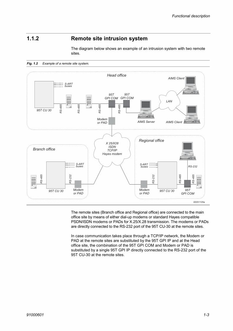
1.1.2 Remote site intrusion systemThe diagram below shows an example of an intrusion system with two remotesites.
Fig. 1.2 Example of a remote site system.
3 3 2 4 5
6 + " 1 $ 1
7 '
'
8
0 '
6 $
/
2
2
# * " "
# * " "
# * " "
2
/
2
2
2
9 5
/
$ 1 4
2
$ 1 4
$ 1 4
The remote sites (Branch office and Regional office) are connected to the mainoffice site by means of either dial-up modems or standard Hayes compatiblePSDN/ISDN modems or PADs for X.25/X.28 transmission. The modems or PADsare directly connected to the RS-232 port of the 95T CU-30 at the remote sites.
In case communication takes place through a TCP/IP network, the Modem orPAD at the remote sites are substituted by the 95T GPI IP and at the Headoffice site, the combination of the 95T GPI COM and Modem or PAD issubstituted by a single 95T GPI IP directly connected to the RS-232 port of the95T CU-30 at the remote sites.

Functional description
910006011-4
1.1.3 System part listThe equipment illustrated and briefly described below is described in detail inthis manual. Please note that the illustrations do not show the equipment in thesame scale.
Type Illustration Description
95T CU-30
+-
Central unit with connection for one S-ART buswith 30 addresses. Can be equipped withExpansion board 95T I/O.12 V/1.5 A power supply for 0.9 A chargingcurrent to a 12 V/15 Ah accumulator.12 V/0.6 A available for external consumption.CPU board with RS-232 and RS-485 interfaces.Mounted in a standard cabinet.
95T I/O Expansion board for three additional S-ARTbuses with 30 addresses each for 95T CU-30and 95T-CU-30-24V.
90T CU-30 Central unit with connection for one S-ART buswith 30 addresses.12 V/1.5 A power supply for 0.9 A chargingcurrent to a 12 V/6.5 Ah accumulator.12 V/0.5 A available for external consumption.CPU board with RS-232 and RS-485 interfaces.Mounted in a small cabinet.
95T CU-30-24V
Central unit with connection for one S-ART buswith 30 addresses. Can be equipped withExpansion board 95T I/O.24 V/3.8 A power supply for 1.2/1.8 A chargingcurrent to two 12 V/24 Ah accumulators.24 V/2.0 or 2.6 An available for externalconsumption.CPU board with RS-232 and RS-485 interfaces.Mounted in a standard cabinet.
95T PS 24/3.8
External power supply (24V, 3.8 A) mounted ina standard cabinet.It has space for two 12V/24Ah accumulators.Built-in S-ARTs for supervision of mains supply,battery charging and battery load test.
95T RKP Remote Keypad.
95T ACM Access control terminal with built-in magstripecard reader.
For a description, please refer to the TechnicalManual for the Thor Access Control System.

Functional description
91000601 1-5
Type Illustration Description
95T ACM-E
Access control terminal with built-in magstripecard reader.
For a description, please refer to the TechnicalManual for the Thor Access Control System.
95T GPI COM
General purpose interface. Can be set-up asModem interface, Printer interface, PC interfaceor Alarm Transmitter interface.
95T GPI BR
Bridge interface to connect two different buslevels together.
95T GPI BRM
Direct Line Modem Interface.Asynchronous 9600 baud modem.
95T GPI DLM
Direct Line Modem Interface.Asynchronous 9600 baud modem.
95T GPI DLC
RS-485 bus amplifier (up to 1.2 km).Note: Only for one address.
99T IPI TCP/IP interface for mounting in an IntrusionCentral Unit or for internal or external mountingin connection with a 95T GPI XXX interface.
95T GPI BRM IP
Similar to the 90T GPI BRM – but withcommunication via a LAN/WAN using TCP/IPinstead of a dedicated line.
95T GPI DLM IP
Similar to the 90T GPI DLM – but withcommunication via a LAN/WAN using TCP/IPinstead of a dedicated line.
95T GPI MI IP
Dial-up modem communicating via aLAN/WAN using TCP/IP instead of the PSTN.
90T S-100 S-ART with alarm/tamper input.
90T S-101 S-ART with alarm/tamper input and 12 V DCoutput.
Functional description
910006011-6
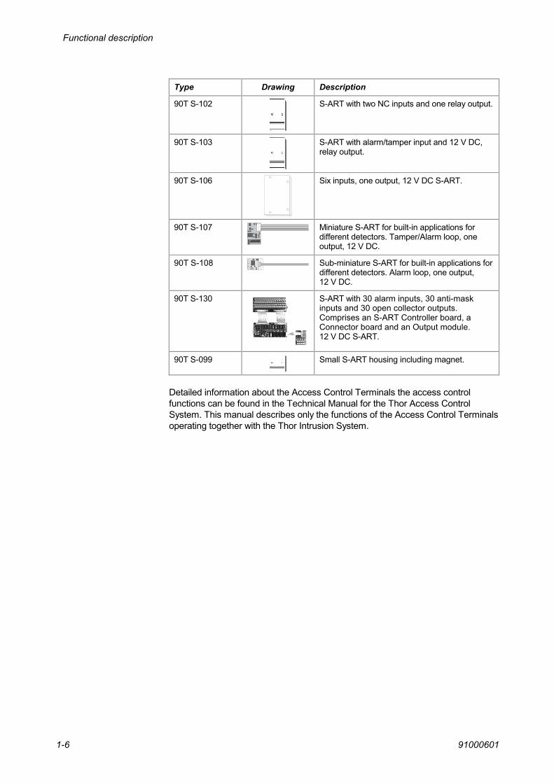
Type Drawing Description
90T S-102 S-ART with two NC inputs and one relay output.
90T S-103 S-ART with alarm/tamper input and 12 V DC,relay output.
90T S-106 Six inputs, one output, 12 V DC S-ART.
90T S-107
Miniature S-ART for built-in applications fordifferent detectors. Tamper/Alarm loop, oneoutput, 12 V DC.
90T S-108 Sub-miniature S-ART for built-in applications fordifferent detectors. Alarm loop, one output,12 V DC.
90T S-130 S-ART with 30 alarm inputs, 30 anti-maskinputs and 30 open collector outputs.Comprises an S-ART Controller board, aConnector board and an Output module.12 V DC S-ART.
90T S-099 Small S-ART housing including magnet.
Detailed information about the Access Control Terminals the access controlfunctions can be found in the Technical Manual for the Thor Access ControlSystem. This manual describes only the functions of the Access Control Terminalsoperating together with the Thor Intrusion System.

Functional description
91000601 1-7
Spare parts
Type Drawing Description
90T CUB-30-2 CPU board for the 90T CU-30 and 95T CU-30Intrusion central unit.
95T PSU 24V-S Power supply 95T CU-30, 95T CU-30-24V, and95T PS 24/3.8.
90T GIB Optocoupler board. Can be used in all 90T GPIinterface types.
104-1x5 Fuse T500 mA for S-ART bus and RS-485 bus.
104-1xD Fuse T1.6 A for CU-30.
104-1xC Fuse T2A for 95T PS 24/3.8.
95 RKP-C Printed circuit board for 95T RKP
133-32S RS-485 line driver
133-301 RS-232 line driver

Functional description
910006011-8
1.2 System descriptionThe Thor system offers a possibility of dividing an installation into 16 zones -really 16 separate systems with a common central unit. A maximum of 250operators using different codes of various priorities are allocated to one or morezones called an area. The total number of areas is 250. The number ofoperators to each individual area is unlimited - so it is allowed to use forexample 200 codes for one area and what is left for the remaining parts of thesystem.
A zone is made up of a number of input circuits (detectors) and possibly someindicating outputs. Each input circuit belongs to one zone only, while outputtypes may represent the individual zone or the complete installation.
Operating is performed by means of remote keypads or card readers (max. 31RKPs or readers - several may be operated at the same time) and someancillary control equipment. The RKPs are individually allocated to one or morezones, while equipment (For example a key-switch) for completion/initiation ofthe setting/unsetting procedure is always allocated to just one zone or to area001 to 016.
Operating on a card reader is, when the system is unset, mainly to open a doorby a card but it is possible to have full access to all the intrusion menus with thesame performance as the operating of the system from a normal Remotekeypad (RKP).
Two kind of operating philosophies are used. Codes allocated to an area, whichis defined as logical, operates in such a way, that zones common to more ofthose areas are not physically set until all such areas have been requested set.The other philosophy is called physical areas, where codes allocated to theareas performs normal physical setting/unsetting of the common zones.
From the time on, a circuit is physically set, until it is unset again, an alarmcondition is indicated by local optical and acoustical signalling devices and byexternal transmission as described in the following pages. Acoustical indicatorsare stopped automatically after typically 3 minutes (programmable), opticalindicators typically by log-on (with code) and transmission signals are typicallyreset, when the alarm message is reset. Automatic alarm reset is included.
Some parts of the installation are always monitored and able to release a localor external alarm - also when the area is unset - this applies for example tomonitoring of the presence of some signalling devices (sirens etc.), junctionboxes and a number of system faults.
By activation of a hold-up pushbutton or by entering a hold-up code, a silentalarm is always released (and transmitted to the alarm station). The hold-upcode feature can be disabled by option setting.
Mains power fault is indicated by a flashing power lamp. Other system faults, i.e.battery fault, are indicated as described by the following pages.
During mains power fault, the built-in rechargeable batteries (max. 2 x 24 Ah)provide power for typical 32 hours of operation, depending on the systemconfiguration (See Section 2.13, Current consumption).

Functional description
91000601 1-9
Two types of inputs are part of the Thor intrusion system, either the bustechniques with the addressable S-ARTs as described in the next section, or thetwo current input loops placed on the CU-board of the central unit.
All inputs and outputs, S-ARTs, normal loop I/O or internal logical systemmessages, are programmable with input or output soft types to give each usedaddress the wanted function. A long list of soft types is available and described inthis section.

Functional description
910006011-10
1.3 S-ARTsThe S-ART (Serial Addressable Receiver Transmitter) is a full custom integratedcircuit, developed for transmission of data on a 2-wire cable and intended for usesuch as identification of each individual detector in alarm systems.Up to 30 S-ARTs may be connected to a 2-wire cable. The two wires distribute thepower supply to the S-ARTs as well as data to and from the S-ARTs.If 12V/24V DC is needed for relays, detectors etc. this demands an extra pair ofwires.
1.3.1 System diagramFour S-ART-lines (buses) may be connected to the S-ART Controller - each buscan handle max. 30 S-ART addresses.
Fig. 1.3 The connection of S-ART lines to the S-ART Controller and the connection of S-ARTs tothe S-ART lines (S-ART bus).
The S-ART controller, placed on the main CPU-board in the Central unit, scansall the connected S-ARTs and gives the changes of the input condition to theMain CPU when they occur. The outputs of the S-ARTs are similarly set or resetby orders from the Main CPU.
1.3.2 Line signalsThe S-ART transmission includes 10 bits.
When an S-ART recognizes its own address, it reacts corresponding to theread/write bit as follows:
1 - Data for the two outputs (OUT 0 and OUT 1) are latched.
2 - Data of the two inputs (IN 0 and IN 1) are transferred to the S-ART controller.

Functional description
91000601 1-11
The line signal is divided into three levels in order to transmit DATA as well asCLOCK.
Fig. 1.4 The three levels of the line signal of the S-ART line (S-ART bus).
When the clock is high (17V), all S-ARTs are power supplied by the S-ARTcontroller via a transistor.
When the clock is low, data are transmitted. Logical "1" is 6.2V (supplied by theS-ART controller) and logical "0" is 0V.
When the S-ART has recognized its address and is ready to transmit input datato the S-ART controller, it makes a short circuit of the line via a resistance of150 Ω in case of a logical "0" and stays in the high impedance state in case of alogical "1", thus maintaining the 6.2V of the S-ART controller.
When the S-ARTs are connected on a cable, the signal shape changes a littledepending on the cable length. On the following two figures is shown a typicalS-ART signal on a 200 m cable and 500 - 700 m cable (6/10 unshielded type).
Fig. 1.5 Signal shape with short cable (< 200m).
Fig. 1.6 Signal shape with long cable (> 500m).

Functional description
910006011-12
1.4 The logical area conceptThe following example concerns a medium size installation and explains someof the facilities of the Thor alarm system.
The installation is divided into 9 areas made up of 8 zones, each consisting of anumber of detectors and indicating equipment. Each area is operatedindividually by means of four operating keypads.
In order to make it possible for each employee to operate his own zone, thezones he has to pass and the common entry/exit zone, the following systemprogramming concerning zone-relationship is made:
Area 01 Zone 01 and 02 Purchasing departmentArea 02 Zone 01, 03 and 05 Shipping officeArea 03 Zone 01, 04 and 05 StockArea 04 Zone 01, 04 and 05 FactoryArea 05 Zone 01 and 06 Sales departmentArea 06 Zone 01, 06 and 07 ManagementArea 07 Zone 01, 06 and 16 Technical departmentArea 08 All zones SystemArea 09 Zone 04 (physical) Stock
Remote Keypad RKP 01 All zonesRemote Keypad RKP 02 Zone 07Remote keypad RKP 03 All zones except zone 07Card Reader RKP 04 Zone 04 (physical)
Set/Unset Key-switch for setting/unsetting the stock (zone 04)Bypass Unit Door contact for start/stop of entry/exit time
To each area 01 to 07 a number of operator codes with priority P0 are attributed.To area 08 belongs an engineer code (P4) and a master manager code (priorityP2) are programmed.
Fig. 1.7 The division of the building into zones.

Functional description
91000601 1-13
The first employee to be at work in the morning has to unlock the main entrancedoor. By doing so, he activates a BYPASS UNIT circuit (input type 05) in thedoor and by that he starts the entry time.
During the entry time, alarm conditions of detectors within the reception aresuppressed. Such circuits (door contacts, volumetric detectors etc.) must bedefined as input type 04 - ENTRY ROUTE.
After having accessed the reception, he logs-on to the RKP 03 by entering hispersonal code (6 digits) and pressing the - key, he unsets all zones of his area.
Hereafter at least one operator of each area should log-on to the system andperform unsetting, as the system keeps track of which areas have been requestedunset and which have not, in order to tell the operator - during the settingprocedure - that he is the last one to leave and that the complete system is set.
Although area 03 and 04 include exactly the same zones, they should still beset/unset individually by an operator of each area. The first person to unset oneof the areas, of course really unsets zone 01, 04 and 05, but they are notphysically set again until area 03 as well as area 04 have been requested set,which means, that employees in the factory do not have to worry whether thestock is set or not - they just perform a normal setting procedure. This type ofareas is called logical areas.
An additional feature is added to the stock, as the door from the factory may beopened by means of a CARD READER 04, which is possible only if the stock isunset. By means of this CARD READER (using card and code), the stock maybe set physically during lunch etc. This area is called a physical area.
In case the management is first at work, they have to unset area 06 by means ofRKP 03 as well as RKP 02, because only zones common to the code and thekeypad are affected. In this case, RKP 02 makes it easy to set zone 07 (andpossibly a safe), when the management leaves for lunch.
Setting is initiated by entering an operator code to the RKP 03 and pressingthe - key upon which the operator is asked to leave. This action normallycompletes the setting procedure by physically setting zones exclusively found inhis area and logically setting zones common to other areas (i.e. the reception). Ifhe is the last one to leave, also an exit tone starts and he has to lock the mainentrance door and hereby stops the exit time.
During the night, goods are delivered to the stock, so zone 04 may be set/unsetalso by other means. Unsetting is performed by unlocking a key-switch (inputtype 25 - SET/UNSET ZONE) and completed by locking the key-switch again -in case of setting faults, the circuits in question are automatically isolated.Completion of setting procedure is indicated by means of a buzzer (output type18 - SET/FAULT).
Most operators are allowed to reset alarm messages within their own area byusing any keypad. Some alarm/fault messages, for example tamper, require amaster manager code or an engineer code.
This installation includes a PROGRAMMER - RKP 01, which can be used forprogramming of the system, but the RKP can also be used for unsetting forexample in the morning. Furthermore this RKP includes all zones of theinstallation and is thus well suited for system test etc. using the manager orengineer code.

Functional description
910006011-14
1.5 InputsThe function of each address from 000 to 250 defined in the system must bedescribed with an input soft type. The relation between input soft types and eachinput address is programmed in Menu 47.
A soft type is a description of the alarm input function of the address to which itis programmed. A full definition of the reaction in unset/set conditions, when andwho can reset messages from which soft types, which output soft types areaffected etc. is provided.
All S-ARTs have two different inputs, an alarm input and a tamper input. Aninput soft type is only connected to the alarm input. The tamper input on eachS-ART address has a predefined tamper function.
In the following, all input soft types available and the allocation of inputaddresses in Thor intrusion system are described.
1.5.1 Overview of input soft typesThe table below provides an overview of the input soft types available.
Alarm reaction by zone: Unsetting, Conditions toInput types UNSET SET Isolation RESET
00 = Not defined -
01 = Normal Night - Intrusion Yes Unset or quiet
02 = Seismic Alarm - Intrusion Yes Unset or quiet
03 = 24h local alarm Intrusion Yes Quiet
04 = Entry Route Intrusion Yes Unset or quiet
05 = Bypass Unit Open to closed stop exit time, closed to open starts entry time.
06 = Normal Night 2h Intrusion Yes Unset or quiet
07 = Tamper Tamper Tamper No Quiet - P3/P4 code
08 = Night Deposit Box Intrusion Yes Unset or quiet
09 = Hold-up 1 Hold-up Hold-up No Quiet
10 = Technical/Film Counter Local Technic Technic 1 Isolation Counter reset
11 = Technical 1 Local Technic Technic 1 Isolation Quiet
12 = Technical 2 Technic 2 Technic 2 Isolation Quiet
13 = System Fault 1 System Fault System Fault No Quiet
14 = System Fault 2 System Fault System Fault No Quiet, automatic
15 = System Fault 3 System Fault System Fault No Quiet - P4 code
16 = System Fault 4 Event-log Event-log No
17 = Key Storage Box Sabotage Intrusion No Quiet - P3/P4 code
18 = Fire Alarm Fire alarm Fire alarm No Quiet
19 = Beam Pair 1 Intrusion Yes Unset or quiet
Continued …

Functional description
91000601 1-15
Alarm reaction by zone: Unsetting, Conditions toInput types UNSET SET Isolation RESET
20 = Beam Pair 2 Intrusion Yes Unset or quiet
21 = Shock Count Intrusion Yes Unset or quiet
22 = Hold-up 2 Hold-up Yes Unset or quiet
23 = Local Perimeter Detection Local Intrusion Yes Unset or quiet
24 = Follow Me Output Type 24 Output Type 24 No
25 = Set/Unset Zone Pulse Open to closed circuit sets or unsets the zone
26 = Set/Unset Zone Level Close = Unset zone, Open = Set zone
27 = Set/Unset Area Pulse Open to closed circuit sets or unsets the area
28 = Set/Unset Area Level Close = Unset area, Open = Set area
29 = Alarm Reset Open to closed circuit resets the alarm messages in the corresponding area
30 = 24 h Seismic Local Intrusion Intrusion Yes Quiet
31 = Night Deposit Box 2 Local Intrusion Intrusion Yes Unset or quiet
32 = Vindicator Lock Event log Yes
33 = High Security – Entry Door Intrusion aftertimer 22 expires
Intrusion afterentry timer expires
Yes
34 = Anti-mask Local Intrusion Local Intrusion Yes
35 = Primary Transmission Fault System Fault System Fault No Quiet, automatic
1.5.2 Input soft type descriptionThe following pages describe the various input soft types available. Duringsystem programming in Menu 47, the input types are allocated to physical inputsin the format:
ZZ TT NNN ISCD
ZZ (01 - 16) is the zone, this input is allocated to, TT is the type of the input,NNN (001-254) refers to a programmable detector name list (the detector nameis shown in the display in case of an alarm etc.) and ISCD refers to specialattributes allocated to this input.
Description of attributes
Attribute Name DescriptionI Isolate The address can be isolated (Max. 1 per zone) in case of setting fault.
S Soak test An alarm condition is not latched but is stored in the event log for the next 14 days. After this,the input is set for normal operation.
C Invert This address is scanned using a protocol with a higher security level. Please note that not allS-ART types support this protocol.
D Doubleknock
An alarm condition is defined as two activations within 5 minutes or an activation with a durationof 10 s or more.

Functional description
910006011-16
Description of soft types
Programming of unused inputs or S-ART addresses.
Can be set/unset. Isolation is possible.External + local alarm by open circuit in set condition.Alarm reset requires quiet & set or unset condition.Circuit attributes: Isolate, Double Knock, Soak Test and Invert.
Can be set/unset. Isolation is possible.To be used for testable seismic detectors.If an input soft type 08 or 31 (Night deposit box) exists within the same zone, thealarm is inhibited during some time (timer 26 delay + duration) in case this timeris started by the input soft type 08 or 31 Night Deposit Box.External + local alarm by open circuit in set condition.Alarm reset requires quiet or unset condition.If an output soft type 19 Test is allocated to the corresponding output address,this is activated for some time (Timer 25 delay) when the setting condition ischanged from set to unset. The purpose of this test signal is to activate the built-in test generator of the detector, and if the input does not react to this by beingactivated within the time window, a fault message of the input is indicated(System Fault 1). The same test can be performed manually in Menu 32 inunset condition or automatically by Timer 16.Circuit attributes: Isolation, Double Knock, Soak Test and Invert.Affects auto alarm reset.
Always set.Local fire door alarm by open circuit in zone unset condition.External + local alarm by open circuit in zone set condition.Direct input/output address relation if output soft type = 14.Alarm reset requires quiet condition.Circuit attributes: Isolation and Invert.
Can be set/unset.Exit time is started by setting the zone.Inhibited during exit time, which is indicated by the buzzer an output soft type 17Entry/Exit Time. The detector can (see Option bit setting, Menu 52) give SetFault indication during the setting procedure.External + local alarm by open circuit at expiration of the exit time if an input softtype 05 Bypass Unit is defined - if not so, entry time starts.Entry time is indicated by the buzzer and output soft type 17 and started by achange of input condition from passive to active - in case an input soft type 05Bypass Unit is defined however, entry time is started by a change of inputcondition from active to passive of input soft type 05.External + local alarm if not unset until entry time expires or in case of an opencircuit in zone set condition, if entry time is not started (by input soft type 05).Alarm reset requires quiet & set or unset condition.Circuit attributes: Isolate, Soak Test and Invert.
00 - Not defined
01 - Normal Night
02 - Seismic Alarm
03 - 24h
04 - Entry Route

Functional description
91000601 1-17
Starts entry time - after exit time - by a change from passive to active.When the input is activated and the system is set, then the entry timer is startedas normal, but if the system still is set when the entry timer expires, then it willcause an external alarm.When exit time is running, then an activation of the input will not stop the exit time.If an input soft type 04 exists in the same zone and the input soft type 04 isactivated before the input soft type 05 then an immediate alarm will be createdwithout Entry time delay.Circuit attributes: Invert.
Can be set/unset. Isolation is possible.External + local alarm by open circuit in set condition.Alarm reset requires quiet or unset condition.When the setting condition is changed from set to unset, a 2 hours timer isstarted (Timer 25 - DURATION). If the input stays passive within this timewindow, a fault condition of the input is released (System Fault 1). Besides fromthis feature, it corresponds in any other respect to input soft type 01.Circuit attributes: Isolation, Double Knock, Soak Test and Invert.Affects auto alarm reset.
Always set.Tamper alarm by open circuit in zone unset condition.External + local alarm by open circuit in zone set condition.Alarm reset requires quiet condition and a P3/P4 code.Circuit attributes: Soak Test and Invert.
Can be set/unset. Isolation is possible.This input type is intended used for the door contact of a night deposit boxtogether with one or more seismic or microphone detectors, input soft type 02within the same zone, monitoring the box, as input soft type 02 is inhibitedduring the time the door is open and for some time hereafter.Inhibited during some time (Timer 26 DURATION), which is started by a changeof input condition from passive to active in set condition. When the input condi-tion returns to passive or at expiration of the duration time, whatever comes first,the delay time of Timer 26 is started.External + local alarm by open circuit at expiration of the duration time (in setcondition).Alarm reset requires quiet or unset condition.Circuit attributes: Isolation, Double Knock, Soak Test and Invert.Affects auto alarm reset.
Always set.External + local hold-up alarm by open circuit.An alarm condition blocks local intruder alarm outputs.Alarm reset requires quiet condition.Circuit attributes: Invert.
Always set.Local technical alarm by open circuit in longer time than indicated in Timer 22(DUR) (accumulated), when the zone is unset.External + local technical alarm by open circuit in longer time than indicated inTimer 22 (DUR) (accumulated), when the zone is set.Alarm reset requires quiet condition and counter reset (by Menu 34).Circuit attributes: Isolate, Invert and Soak Test.
05 - Bypass Unit
06 - Normal Night 2h
07 - Tamper
08 - Night Deposit Box
09 - Hold-up 1
10 - Technical/Film Counter

Functional description
910006011-18
Always set. Isolation is possible.Local technical alarm by open circuit in zone unset condition.External + local technical alarm by open circuit in zone set condition.A change from open to closed circuit is logged.Alarm reset requires quiet condition.Circuit attributes: Isolate, Invert and Soak Test.
Always set. Isolation is possible.External + local technical alarm by open circuit.A change from open to closed circuit is logged.Alarm reset requires quiet condition.Circuit attributes: Isolate, Invert and Soak Test.
Always set.External + local system fault by "open" circuit.Fault reset requires quiet condition.Used for fault monitoring i.e. battery fault, 1h mains fault.Automatic battery test is performed each 24 hours (15 s) and a short "fuse" testeach 5 s.Circuit attributes: Invert.
Always set.External system fault by "open" circuit.Automatic fault reset by quiet condition.Used for service mode indication and transmission line fault.Circuit attributes: Invert.
Always set.External + local system fault by "open" circuit.Fault reset requires quiet condition and engineer code.Used for fault monitoring i.e. fatal CPU-reset.Circuit attributes: Invert.
Always set.Just a message in the event-log by "open" circuit.Intended use for internal fault monitoring i.e. non-fatal CPU-reset and mainspower fault (which is also indicated by a flashing power lamp).Circuit attributes: Invert.
Always set.Sabotage alarm by open circuit in zone unset condition.External + local alarm by open circuit in zone set condition. The monitoring ofthe input is suppressed after setting the zone during a time defined by the Timer21 (DURATION). An existing sabotage message from a Key Storage Box will bereset at the same time (independent of the input status - active or passive). AfterTimer 21 (DURATION) runs out a new alarm will be activated in case the inputis still active. Manual reset is also possible by a P3 or P4 code.Circuit attributes: Invert and Soak test
Always set.External + local fire alarm by open circuit.Alarm reset requires quiet condition.Circuit attributes: Isolate, Invert and Soak test
11 - Technical 1
12 - Technical 2
13 - System Fault 1
14 - System Fault 2
15 - System Fault 3
16 - System Fault 4
17 - Key Storage Box
18 - Fire alarm

Functional description
91000601 1-19
Can be set/unset. Isolation is possible.In set condition, a change of input from passive to active starts a timer (Timer27). If input soft type Beam Pair 2 (set - within the same zone) is activated withinthis time window, the alarm condition is latched as external + local alarm. Bothinputs are logged. Only one Beam Pair 1 in each zone must be programmed.Alarm reset requires quiet or unset condition.Circuit attributes: Isolation, Double Knock, Soak Test and Invert.Affects auto alarm reset.
Can be set/unset. Isolation is possible.In set condition, a change of input from passive to active starts a timer (Timer27). If input soft type Beam Pair 1 (set - within the same zone) is activated withinthis time window, the alarm condition is latched as external + local alarm. Bothinputs are logged. Only one Beam Pair 2 in each zone must be programmed.Alarm reset requires quiet or unset condition.Circuit attributes: Isolation, Double Knock, Soak Test and Invert.Affects auto alarm reset.
Always set. Isolation is possible.In set condition the input type counts a number of pulses (programmable bymeans of Timer 20 DELAY) in a time window (specified by Timer 20DURATION) and will generate an external (Output soft type 37) and local alarm(Output soft type 05) condition if the number of pulses exceeds the specified. Inunset condition, it will generate a local alarm.Application: Seismic Shock detectors.Alarm reset requires quiet or unset condition.Circuit attributes: Isolation, Double Knock, Soak Test and Invert.Affects auto alarm reset.
Can be set/unset. Isolation is possible.External + local hold-up alarm by open circuit when in set condition.An alarm condition blocks local intruder alarm outputs.Alarm reset requires quiet condition.Circuit attributes: Isolation, Invert.
Can be set/unset. Isolation is possible.Local alarm only by open circuit in set condition.Activates output soft type01, 29 and 23 (if programmed on same S-ARTaddress). The change from passive to active on the input in set condition startsTimer 19 (DURATION). If another input soft type 23 is activated before the timerhas expired (in the same zone) then output soft type also is activated.Application: Perimeter detection with different local output reactions provoked bydifferent input events.Alarm reset requires quiet & set or unset condition.Circuit attributes: Isolate, Double Knock, Soak Test and Invert.
An open circuit is indicated by output soft type 24 - Follow Input.Circuit attributes: Invert.
19 - Beam Pair 1
20 - Beam Pair 2
21 - Shock Count
22 - Hold-up 2
23 - Local Perimeter Detection
24 - Follow Me

Functional description
910006011-20
-A change from open to closed circuit changes the zone set condition - set tounset or unset to set (physically).Successful setting is indicated by a short activation of output soft type 18. Incase of maximum two active circuits, they are isolated, indicated by activatingoutput soft type 18 for a few seconds (programmable). In case of more than twoactive circuits or non-reset alarm/fault messages within the zone, setting is stillcarried out, but an alarm condition is released and output soft type 18 Set/Faultis activated until log-on to the keypad.The priority level of this input type is equal to any access code - they overrideone another.Circuit attributes: Invert.
-When the input is passive, the zone is unset. When the input is active, the zoneis set (physically).Successful setting is indicated by a short activation of output soft type 18. Incase of maximum one active circuit, this is isolated, indicated by activatingoutput soft type 18 for a few seconds (programmable). In case of more than oneactive circuit or non-reset alarm/fault messages within the zone, setting is stillcarried out, but an alarm condition is released and output soft type 18 Set/Faultis activated until log-on to the keypad.The priority level of this input type is equal to any access code - they overrideone another.Circuit attributes: Invert.
-Setting/Unsetting is performed physical or logical as defined during areaprogramming. In other respect, it corresponds to input soft type 25. Can beallocated to area 001 to 016 only.Circuit attributes: Invert.
-Setting/Unsetting is performed physical or logical as defined during areaprogramming. In other respect, it corresponds to input soft type 26. Can beallocated to area 001 to 016 only.Circuit attributes: Invert.
-When the input changes from active to passive all alarm messages in the areaNo. specified by the programmed zone no., that can be reset, will be reset. Thealarms that are reset will be logged with the input number as operator.
25 - Set/Unset Zone Pulse
26 - Set/Unset Zone level
27 - Set/Unset Area Pulse
28 - Set/Unset Area Level
29 - Alarm Reset

Functional description
91000601 1-21
Always set. Isolation is possible.To be used for testable seismic detectors.If an input soft type 08 or 31 (Night deposit box) exists within the same zone, thealarm is inhibited during some time (Timer 26 delay + duration) in case this timeris started by the input soft type 08 or 31 Night Deposit Box.External + local alarm by open circuit.Alarm reset requires quiet condition.If an output soft type 19 Test is allocated to the corresponding output address,this is activated for some time (Timer 25 delay) when the setting condition forthe corresponding zone is changed from set to unset. The purpose of this testsignal is to activate the built-in test generator of the detector, and if the inputdoes not react to this by being activated within the time window, a fault messageof the input is indicated (System Fault 1). The same test can be performedmanually in Menu 32 in zone unset condition or automatically by Timer 16.Circuit attributes: Isolation, Double Knock, Soak Test and Invert.Affects auto alarm reset.
Always set. Isolation is possible.This input type is intended used for the door contact of a night deposit boxtogether with one or more seismic or microphone detectors, input soft type 02 or30 within the same zone, monitoring the box, as input soft type 02 or 30 isinhibited during the time the door is open and for some time hereafter.Inhibited during some time (Timer 26 DURATION), which is started by a changeof input condition from passive to active in set condition. When the input condi-tion returns to passive or at expiration of the duration time, whatever comes first,the delay time of Timer 26 is started.External + local alarm by open circuit at expiration of the duration.Alarm reset requires quiet condition.Circuit attributes: Isolation, Double Knock, Soak Test and Invert.Affects auto alarm reset.
Can be set/unset. Isolation possibleThe input soft type can be set or unset. It will generate a message in the eventlog by “open” circuit in set condition. If you try to set the input with the inputactive it will generate a set fault.
Isolation is possibleIn set condition then an active input will start the entry time (if entry time isprogrammed to 0, then an alarm will be produced).In unset condition then an active input in more than the programmed time(Timer 22 – delay) will give an alarm.
Always set. Isolation is possible.This input soft type is always set, and generates a local alarm in open circuitcondition.It sends special Anti Mask message on the MMP – bus when an alarm occurs.
-Used with input soft type 78 Incom Trans Blk. When using a primary and asecondary modem interface, a test mail can be set up for each (test mail 1 andtest mail 2). The frequency between these is set by timer 28 and timer 17duration. If input soft type 78 becomes active, then test mail 2 will shift frequencyto timer 17 delay. In other words, if your secondary modem sends a test mailevery 24 hour in normal condition, it can shift to sending a test mail every 1 hourif the primary modem is off.
30 –24h Seismic
31 – 24h Night Deposit Box
32 - Vindicator lock
33 - High Security – Entry Door
34 - Anti-mask
35 – PrimaryTransmission Fault

Functional description
910006011-22
1.5.3 Input addresses and standard programmingThe relationship between each detector address (i.e. number displayed duringoperating and programming) and the physical location is listed below.In addition, the programming made from the factory concerning input type,circuit name and zone relationship are listed (by default).
95T CU30 on-board inputs
Inputaddress
Terminalnumber Designation
By default:Zone Type Name Remarks
1 P3-1/3 Input loop 01 00 001 End of line resistor 10 kΩ
2 P3-2/3 Input loop 01 00 001 End of line resistor 10 kΩ
Remote operating keypads, etc.
Inputaddress
Terminalnumber Designation
By default:Zone Type Name Remarks
17 - 24 485 Bus Vault controllerinputs
01 00 001 Vault controller inputs
31 - 61 485 Bus Reader inputs 01 00 001 Reader soft type 99 (ReaderNo. 01 - 31)
500 - 531 485 Bus System Fault 16 16 099 Communication/TamperRKP/ Central unit 00 - 31
532 Internal Printer fault 16 15 100 Internal printer (paper low)
Main controller internal addresses
Inputaddress
Terminalnumber Designation
By default:Zone Type Name Remarks
076 485 bus Minitel fault 16 16 076 PC connection fault
077 * 485 bus Minitel fault 16 15 077 INCOM hardware fault
078 * 485 bus Minitel fault 16 14 078 Alarm transmission blocked
079 485 bus Minitel fault 16 14 079 Telephone line fault
080 485 bus Minitel fault 16 16 080 3 wrong code attempts on Minitel
081 Internal System fault 16 13 081 Battery fault
082 Internal System fault 16 16 082 Mains power fault
083 Internal System fault 16 15 083 S-ART power fault
084 Internal System fault 16 13 084 Mains fault 1 hour
085 Internal System fault 16 14 085 Service mode
086 Internal System fault 16 15 086 RAM fault
087 Internal System fault 16 15 087 EPROM fault
088 Internal System fault 16 16 088 Watchdog reset
089 Internal Tamper C089 16 07 089 Intrusion via RS-485 bus
090 Internal Tamper C090 16 16 090 Three faulty codes on a RKP
091 Internal Tamper C091 16 00 091 Remote printer fault
092 Internal Tamper C092 16 07 092 Site code error (from terminal)
* See the section, Input addresses 077 and 078, on the following page

Functional description
91000601 1-23
Input addresses 077 and 078
The input addresses 077and 078 can be activated in the CU on the main RS-485 bus in case of a transmission fault (after five retransmissions of the samealarm or event mail) from a 95T GPI COM (IP) interface in modem interfacemode.This can be used for activating a backup transmission path if the maintransmission path fails and it is impossible to transmit the mail on a secondarycall number or the modem interface or transmitter on the remote site isprogrammed with a single call number or address only.
In the example below, the main transmission path is through LAN and WAN viarouters. The backup transmission path is through GPI COMs via modems andthe public switched telephone network (PSTN).
Fig. 1.8 Example of intrusion system with a main and a backup transmission path
01020501a
Remote site
95T GPI COM
95T CU 30 with 99T IPI
Modem
PSTN
WANLANRouter Router
95T CU 30 with 99T IPI
Modem
95T GPI COM
LAN
95T GPI COM
Central siteAIMS
Main transmission path
Backup transmission path
A backup transmitter cannot be used together with a transmitter in interfacenetwork mode since there will be no alarm reaction because the transmitter isalways on-line. All alarm and event mails are retransmitted forever and there willbe no alarm reaction.
In the backup transmission path, the GPI COM on the remote site will remain insleep mode as long as the main transmission path is operating properly. If thistranmission path fails, the CU input address 078 will be activated and wake theGPI COM from sleep mode for transmission of mails. It remain activated until amail is transmitted correctly from the GPI COM.Any type of mail – very often a routine check response from the AIMS – willpassivate the input address 078 and return the GPI COM to sleep mode.
Input address 077 will also be activated but will be passivated immediately if theGPI COM address is different from 01.
Note

Functional description
910006011-24
The following reactions will take place in normal mode depending however onthe configuration of the modem interface.
The GPI COM interface will go out of sleep mode in the following situations:
If the input address 078 becomes active.
If the GPI COM interface is a backup transmitter and it receives a devicetable without other transmitters (if the main transmitter is disconnected fromthe THOR bus)
The GPI COM interface will go into sleep mode in the following situations:
If the GPI COM interface has address 01, the modem is a Hayes type andanother GPI COM is online on address 02.
If the GPI COM interface has an address different from 01, the modem mustbe either a Hayes type or an ISDN type and another GPI COM is online onaddress 01.
The main transmitter is a TCP/IP transmitter on address 01 with a backuptransmitter on any other address (02 to 31).In this configuration the CU input address 078 (Primary transmitter transmissionfault) is used for activating the backup transmission path.The CU input address 077 (Backup transmitter transmission fault) can be usedfor activating an additional digital alarm transmitter to operate as a secondarybackup transmitter.
Typical backupconfiguration

Functional description
91000601 1-25
Video front-end addresses
Input address Terminal number Designation Remarks30 + Device addressof Video Front-end
RS-485 bus Boot
500 + Device addressof Video Front-end
RS-485 bus Tamper
025 RS-485 bus Video Loss Camera input1
026 RS-485 bus Video Loss Camera input 2
027 RS-485 bus Video Loss Camera input 3
028 RS-485 bus Video Loss Camera input 4
029 RS-485 bus Video Loss Camera input 5
070 RS-485 bus Video Loss Camera input 6
071 RS-485 bus Video Loss Camera input 7
072 RS-485 bus Video Loss Camera input 8
S-ART circuits
Inputaddress
Designation By default:Zone Type Name Remarks
100 – 129130
Cir. 100-129Tamper 130
0116
0007
001093
S-ART Line 1 (00 to 29)Pseudo S-ART (30)
131 - 199 Not available
200 – 229230
Cir. 200-229Tamper 230
0116
0007
001093
S-ART Line 2 (00 to 29)Pseudo S-ART (30)
231 – 299 Not available
300 – 329330
Cir. 300-329Tamper 330
0116
0007
001093
S-ART Line 3 (00 to 29)Pseudo S-ART (30)
331 - 399 Not available
400 – 429430
Cir. 400-429Tamper 430
0116
0007
001093
S-ART Line 4 (00 to 29)Pseudo S-ART (30)
431 - 499 Not available

Functional description
910006011-26
1.6 OutputsLike the inputs, each output address defined in the system must be describedwith an output soft type. Programming of output soft types to output addressesare done in Menu 49.
The output soft type describes the exact reaction of the corresponding output towhich it is programmed that includes, which input soft type activates whichoutput soft type, when the output soft types are reset again etc.
All output soft types (except a few) can be connected to a zone and will thenonly activate when a corresponding input soft type in this zone is in alarm, or itcan be a system type, which then will activate from alarms in any zone.
Each S-ART address can be programmed with an input soft type and an outputsoft type that can work fully independent. They can even be programmed todifferent zones if wanted.
In the following is described all output soft types available and the allocation ofoutput addresses in the Thor Intrusion System.
1.6.1 Overview output soft typesThe table below provides an overview of the output soft types available.
Primary output function
Output typesLocal alarm
indicatorLocal
controlExternal
signalling Remarks
00 = Not defined -
01 = Common Alarm X Siren, bell or strobe
02 = Tamper Alarm X Siren or bell
04 = Seismic Alarm X Siren or bell
05 = Local Shock Count Alarm X Siren or bell
06 = Set/Unset (Zone) X Lamp
07 = Hold-up Alarm X Lamp
08 = More Than One Hold-up Alarm X Siren or bell
09 = Technical Alarm 1 X Bell or buzzer
10 = Technical Alarm 2 X Bell or buzzer
12 = System Fault X Bell or buzzer
14 = Local Alarm X Bell or buzzer
16 = SW.Power X Switched power supply
17 = Entry/Exit X Buzzer
18 = Set/Fault X Buzzer
19 = Test X For detector test
20 = Fire Reset X Power supply for fire
Continued …

Functional description
91000601 1-27
Primary output function
Output typesLocal alarm
indicatorLocal
controlExternal
signalling Remarks
21 = Fire Alarm X -
22 = Glass Break X Reset signal
23 = Perimeter 1st Detector X -
24 = Follow Input X Buzzer etc.
25 = Local Alarm Function X Alarm Functions
26 = Auto-Set Prewarning X Buzzer
27 = Perimeter 2nd Detector X -
29 = Common Alarm 2 X Siren, bell or strobe
32 = Set/Unset Area X Transmitter input
33 = Intrusion X Transmitter input
34 = Tamper X Transmitter input
35 = More than One Alarm X Transmitter input
36 = Seismic Alarm X Transmitter input
37 = External Shock Count Alarm X Transmitter input
38 = Set/Unset X Transmitter input
39 = Hold-up/Duress X Transmitter input
40 = Duress X Transmitter input
41 = Technical 1 X Transmitter input
42 = Technical 2 X Transmitter input
43 = Transmission Test 1 X Transmitter input
44 = Trouble X Transmitter input
45 = 1h Mains Fault X Transmitter input
46 = Fire Alarm X Transmitter input
47 = Isolation X Transmitter input
48 = CPU-Reset X Transmitter input
49 = Transmission Test 2 X Transmitter input
50 = Anti Hostage X Lamp

Functional description
910006011-28
1.6.2 Output soft type descriptionThe following pages describe in detail the various input soft types available
Programmed for unused outputs.
Activated by intruder alarm from input soft types 01, 02, 03, 04, 06, 07, 08 19+20and 21. Passivated by timer or at log-on.
Activated by tamper alarm from input soft type 07.Passivated by timer or at log-on.
Activated by intruder alarm from input soft type 02.
Passivated by timer or at log-on (local output).
Activated by intruder alarm from input soft type 21 (Shock Count) in Set andUnset condition.Passivated by timer or at log-on (local output).
Activated by zone set with no isolations (after exit time). Please note that allzones (also unused zones) must be set, before a System set output will beactivated.
Activated by hold-up alarm from input soft types 09 and 22. Blocks output softtypes 01, 02, 04, 14, 29 and the internal buzzer.Passivated when all such messages are reset.
The output will activate only if more than one Hold-up alarm from the followinginput soft types has occurred: Input soft types 09 or 22. The output is passivatedagain when the number of alarms is 1 or 0 or by the timer programmed to theoutput soft type. Is used as an transmission output soft type.
Follows input soft type 11 input condition - active or passive.
Activated by technical alarm from input soft type 12.Passivated by timer or at log-on.
Activated by system fault from input soft type 13 or 15.Passivated by timer or at log-on.
Activated by local fire door alarm from input soft type 03. Direct input/outputaddress relation.Output is following the corresponding input condition.
Activated during log-on to a keypad within the zone and when one or more ofinput soft types 01 - 04 are physically set. Can be used to control power forUltrasonic detectors.
Activated during entry and exit time.A Timer No. (7 - 28) can be connected to the output soft type for creating a specialTimer type but the Duration of this Timer must then be programmed to 999.
Activated for a short time (normally 2 s - in case of isolations 5 s) to indicatecompletion of the setting procedure. Activated until log-on in case of exit faults.
00 - Not defined
01 - Common Alarm 1
02 - Tamper Alarm
04 - Seismic Alarm
05 – Local Shock Count Alarm
06 - Set/Unset
07 - Hold-up Alarm
08 – More than one Hold-up alarm
09 – Technical Alarm 1
10 – Technical Alarm 2
12 - System Fault
14 - Local Alarm
16 - SW. Power
17 - Entry/Exit
18 - Set/Fault

Functional description
91000601 1-29
Active during test Menu 32 - Walk/Seismic Test - in order to check passiveinfrared detectors, which have the option to control the walk test lamp by anon/off signal, and in order to test the reaction of seismic detectors etc., whichhave a built-in test generator. The Test soft type must in this case beprogrammed on an address with a Seismic input soft type 02 and with the samezone number as the input address.
Normally activated - passivated for a short time by performing reset of fire alarmmessages (input soft type 18) by pressing the Alarm reset pushbutton .The Fire alarm detector scanning is suppressed during the following 3 seconds(preprogrammed to use Timer 12 DURATION).
Activated by fire alarm input soft type 18. Passivated by timer or log-on.
Normally activated - passivated for a short time (defined by timer 3 DURATION)by performing reset of intrusion alarm messages (input soft types 1 and 3) bypressing the Alarm reset pushbutton . The detector scanning is suppressedduring the following seconds (Timer 3 DURATION plus 1 second).
Activated after an alarm from input soft type 23 if programmed on the sameaddress as the input soft type 23. Passivated by timer or at log-on.
Activated during the time an input soft type 24 - Follow Me - is active (by zone).
If the output address is programmed with the output soft type 25, then thisoutput is reset at logon to a keypad within the zone (like a siren output). Theoutput soft type 25 must not be programmed with zone 00 but only another zoneNo. included in the code/area that must reset the output.If no output soft type is programmed to the output address, then the output willwork as a Transmission output which are reset when the inputs to the equationare FALSE (all input messages reset from the display buffer).
Activated for some time (programmable by Timer 29), or until log-on to akeypad, 10 minutes before automatic setting. Auto-set may be delayed (onetime only) by calling Menu 14 on any remote keypad. If the zone No. is between01 to 16, the output will be activated when the zone is included in an area whichmakes an automatic setting. If the zone No. is 00 the, output will be activated forall areas making automatic setting.
Activated after an alarm from input soft type 23 if another alarm from anotherinput soft type 23 already exists but within a period of time defined by Timer 19(DURATION). Passivated by timer or at log-on.
Activated by intruder alarm from input soft types 01, 02, 03, 04, 06, 07, 08, 19 +20 and 21. Passivated by timer or at log-on. If this output soft type is programmedwith zone 00 (common), the output will be triggered only once, i.e. not re-triggeredby a new alarm condition after Auto Alarm Reset.
Activated when the area is physically set (before exit time). Isolated circuits maybe present. Passivated when just one circuit is unset. Can be allocated to area001 to 016 only!
Activated by external intruder alarm from input soft types 01, 02, 03, 04, 06, 07(only if zone set), 08, 19+20 and 21.Passivated by timer or when all such messages are reset.
19 - Test
20 - Fire Reset
21 - Fire alarm
22 - Glass Break
23 - Perimeter 1st Detector
24 - Follow Input
25 - Local Alarm Function
26 - Auto-set Prewarning
27 - Perimeter 2nd Detector
29 - Common Alarm 2
32 - Set/Unset Area
33 - Intrusion

Functional description
910006011-30
Activated by tamper alarm from input soft type 07.Passivated by timer or when all such messages are reset.
The output will activate only if more than one intruder alarm from the followinginput soft types have occurred: 01, 02, 03, 04, 06, 08, 19, 20 or 21. These are allthe Intruder input soft types excluding Technical, Fire and Hold-up alarms. Theoutput is passivated again when the number of alarms is 1 or 0 or by the timerprogrammed to the output soft type. Is used as an transmission output soft type.
Activated by intruder alarm from input soft type 02.Passivated by timer or when all such messages are reset (transmission output).
Activated by intruder alarm from input soft type 21 (Shock Count) in Setcondition.Passivated by timer or when all such messages are reset (transmission output).
Activated when the zone is physically set (before exit time). Isolated circuits maybe present. Passivated when just one circuit is unset.Please note that all zones (also unused zones) must be set, before a System setoutput will be activated.
Activated by a hold-up alarm from input soft types 09 and 22 or when a duresscode is used.Passivated by timer or when all such messages are reset.Please note that a timer with a limited time must be used for this output softtype, if the Hold-up code feature is enabled.
Activated by a hold-up alarm when a duress code is used.Passivated by timer.Please note that a timer with a limited time must be used for this output softtype, if the Hold-up code feature is enabled.
Activated by external Technical Alarm 1 from input soft type 11.Passivated by timer or when all such messages are reset.
Activated by external Technical Alarm 2 from input soft type 12.Passivated by timer or when all such messages are reset.
The soft type is controlled by Timer 28 which is programmed in 0.1 hours. TheTimer DURATION specifies the frequency of the output activation (time betweeneach activation). The Timer DELAY defines the time between when theprogramming is done and the first activation. If the Timer Type is programmedto type 3, the output soft type 43 will be activated only if the zone (01-16) orsystem (00) is set. All other Timer Types will activate the soft type in set or unsetcondition. The soft type can be connected to one of the standard Timers from 07to 27. This timer will then - by the DURATION - control the activation time (pulsewidth). When output soft type 43 (common) is activated then a TransmissionTest 1 mail is sent to bus device type: Modem interface Online (14H).
Activated by system fault from input soft type 13, 14, 15 or 35.Passivated by timer or when all such messages are reset.
NOTE! Activated during service mode (engineer at site) and automaticallypassivated (if no other system fault messages are present) when service modeis reset - if the internal input address 085 is programmed as soft type 14.
34 - Tamper
35 – More than one alarm
36 - Seismic Alarm
37 – External Shock Count Alarm
38 - Set/Unset
39 - Hold-up/Duress
40 - Duress
41 - Technical 1
42 - Technical 2
43 - Transmission Test 1
44 - Trouble

Functional description
91000601 1-31
Activated after 1 hour (or programmable time by Timer 06) of mains power fault.Passivated by timer or when the message is reset.Note! Must only be programmed in zone 00 (total system).
Activated by fire alarm input soft type 18. Passivated by timer or when all suchmessages are reset.
Activated when one or more circuits are isolated.Passivated when all such isolations are removed (by unsetting).
Activated for a short time upon non-fatal CPU-reset.
This output soft type works exactly as output soft type 43, but with Timer 17.It is possible to use the Minitel output message for the transmission test on theexternal dialer, by programming the output soft types 43 and 49 on the Miniteloutputs (900 – 999), and programming Timer 28 and 17.When output soft type 49 (common) is activated, then a Transmission Test 2mail is sent to bus device type: Modem interface Online (14H).
Active when entering code and unsetting area consisting of zone 15.Deactivated when all detectors in zone 15 are activated and entering the samecode and unset again.
45 - 1h Mains Fault
46 - Fire alarm
47 - Isolation
48 - CPU-Reset
49 - Transmission Test 2
50 – Anti Hostage

Functional description
910006011-32
1.6.3 Output addresses and standard programmingThe relationship between each output address (i.e. output number displayedduring programming, etc.) and the physical location is listed below. It also appearswhich programming is already made from the factory.
95T CU-30 on-board outputs
Outputaddress
Terminalnumber Designation
By default:Zone Type Remarks
001 P5-1/5 O 1 00 00 NPN transistor output
002 P5-2/5 O 2 00 00 NPN transistor output
003 P5-3/5 O 3 00 00 NPN transistor output
004 P5-4/5 O 4 00 00 NPN transistor output
005 P6-1/6 O 5 00 00 NPN transistor output
006 P6-2/6 O 6 00 00 NPN transistor output
007 P6-3/6 O 7 00 00 NPN transistor output
008 P4 O 8 00 00 Relay output
S-ART lines (Main Controller)
Outputaddress
Terminalnumber Designation
By default:Zone Type Remarks
100-129 P7-1/2 Out 100-129 00 00 S-ART outputs line 1 (00 to 29)
130-199 Not available
200-229 P8-1/2 Out 200-229 00 00 S-ART outputs line 2 (00 to 29)
230-299 Not available
300-329 P9-1/2 Out 300-329 00 00 S-ART outputs line 3 (00 to 29)
330-399 Not available
400-429 P10-1/2 Out 400-429 00 00 S-ART outputs line 4 (00 to 29)
Transmission outputs (logical)
Outputaddress
Terminalnumber Designation
By default:Zone Type Remarks
900 RS-485 Free 00 00
901 RS-485 Mains fault (1 h) 00 45
902 RS-485 Watchdog reset 00 48
903 RS-485 Problem 00 44
904 RS-485 Isolation 00 47
905-909 RS-485 Free 00 00
910 RS-485 Fire 00 46
Continued …

Functional description
91000601 1-33
Outputaddress
Terminalnumber Designation
By default:Zone Type Remarks
911-919 RS-485 Free 00 00
920 RS-485 Hold-up 00 39
921-929 RS-485 Free 00 00
930 RS-485 Sabotage 00 34
931-939 RS-485 Free 00 00
940 RS-485 Intrusion 00 33
941-949 RS-485 Free 00 00
950 RS-485 System set 00 38
951-959 RS-485 Free 00 00
960 RS-485 System set 00 32
961-969 RS-485 Free 00 00
970 RS-485 Tech. alarm 1 00 41
971979 RS-485 Free 00 00
980 RS-485 Tech. alarm 2 00 42
981-989 RS-485 Free 00 00
990 RS-485 Cyclic test 00 43
991-999 RS-485 Free 00 00

Functional description
910006011-34
1.7 Reaction tablesThe following sections provide reaction tables for local alarm/fault outputs,transmission outputs, and various other outputs
1.7.1 Reaction table – local alarm/fault outputsThe table below illustrates, which output types are affected by an active condition ofthe different input types (described by input type number and name). The outputs aredescribed using a short form output name and the output type number.
S The output is activated by the event in zone (or circuit) set condition.U The output is activated by the event in zone unset condition.
(T) The output is activated for a short fixed time.
Output type
Input type
AlarmO01O29
Tamper
O02
Seismic
004
Hold-up
O07
Tech1
O09
Tech2
O10
Fault
O12
Local
O14
Fire
O21
1stdetec.O23
Follow
O24
2nddet.O27
01 - Normal Night S
02 - Seismic alarm S S
03 – 24 h S U
04 - Entry Route S
05 - Bypass Unit
06 - Normal Night 2 h S
07 - Tamper S S U
08 - Night Deposit Box S
09 - Hold-up 1 S U
10 - Technical/Film counter S U
11 - Technical 1 S U
12 - Technical 2 S U
13 - System Fault 1 S U
14 - System Fault 2 S U
15 - System Fault 3
16 - System Fault 4
17 - Key Storage Box S S U
18 - Fire Alarm S U
19 - Beam Pair 1 S
20 - Beam Pair 2 S
21 - Shock Count S
22 - Hold-up 2 S
23 - Local Perimeter Detection S
24 - Follow Me S S
25 - Set/Unset Zone Pulse S U
26 - Set/Unset Zone Level
27 - Set/Unset Area Pulse
28 - S/Unset Area Level
29 - Alarm Reset
30 - 24 h Seismic S U S U
31 - Night Deposit Box 2 S U
Continued …

Functional description
91000601 1-35
Output type
Input type
AlarmO01O29
Tamper
O02
Seismic
004
Hold-up
O07
Tech1
O09
Tech2
O10
Fault
O12
Local
O14
Fire
O21
1stdetec.O23
Follow
O24
2nddet.O27
32 = Vindicator Lock
33 = High Security - Entry Door S U
34 = Anti-mask S U
35 = Primary Transmission Fault
S U
The outputs are reset by timer or at log-on, except for Hold-up O07, which is notreset until the last Hold-up message is erased from the alarm list, and Tech. 1O09 and Follow O24 which follows the corresponding input conditions.
1.7.2 Reaction table – transmission outputsThe table below illustrates, which output types are affected by an active condition ofthe different input types (described by input type number and name). The outputs aredescribed using a short form output name and the output type number.
S The output is activated by the event in zone (or circuit) set condition.U The output is activated by the event in zone unset condition.
(T) The output is activated for a short fixed time.
Output type
Input type
Intrusion
O33
Tamper
O34
Seismic
O36
Hold-up
O39
Duress
O40
Tech1
O41
Tech2
O42
Trouble
O44
1 hMainsO45
Fire
O46
CPUResetO48
01 - Normal Night S
02 - Seismic alarm S S
03 - 24 hour S
04 - Entry Route S
05 - Bypass Unit
06 - Normal Night 2h S
07 - Tamper S S U
08 - Night Deposit Box S
09 - Hold-up 1 S U
10 - Technical/Film counter S
11 - Technical 1 S
12 - Technical 2 S U
13 - System Fault 1 S U (S U)
14 - System Fault 2 S U
15 - System Fault 3 S U
16 - System Fault 4
17 - Key Storage Box S S U
18 - Fire S
19 - Beam Pair 1 S
20 - Beam Pair 2 S
21 - Shock Count S
22 - Hold-up 2 S
23 - Local Perimeter Detection
24 - Follow Me
Continued …

Functional description
910006011-36
Output type
Input type
Intrusion
O33
Tamper
O34
Seismic
O36
Hold-up
O39
Duress
O40
Tech1
O41
Tech2
O42
Trouble
O44
1 hMainsO45
Fire
O46
CPUResetO48
25 - Set/Unset Zone Pulse S U
26 - Set/Unset Zone Level
27 - Set/Unset Area Pulse
28 - Set/Unset Area Level
29 - Alarm Reset
30 - 24 h Seismic S S
31 - 24h Night Deposit Box S
32 - Vindicator Lock
33 - High Security - Entry Door S
34 = Anti-mask
35 = Primary Transmission Fault
SU
Non-fatal reset (T)
The outputs are reset, when the last message is erased from the alarm list.
1.7.3 Reaction table – various outputsThe table below shows the output types affected by certain events. The outputsare described using a short form name and the output type number.
A Indicates that the output is activated.(A) Indicates that isolations may be carried out automatically when the setting is
performed by means of a remote control device.R Indicates that the output is reset to the normal condition.T Indicates that the output is activated for a programmed time. Timer
allocation and time set-up are determined during system programming(T) Indicates that the output is activated for a short fixed time.
Output type/timer
Action
Set/unsetO06O38
SWpowerO02
Entry/exitO17
Set/faultO18
Test
O19
FireresetO20
GlassbreakO22
AutosetO26
Set/unsetO32
Trans.testO43
Isolation
O47
Log-on to RKP A R
Initiate setting A T
Exit fault A
Complete setting A A R (T) R A (A)
Initiate unsetting T
Entry fault
Complete unsetting R R R R R
Alarm reset (T) T
Isolating circuits A
Walk test, Menu 32 A
Time-prog. set A A T A (A)
Timer 28 T
All quiet

Functional description
91000601 1-37
1.8 Timers and timer functionsThe following sections describe the timers available, timer duration functionsand delay functions, output soft types and software timer types.
1.8.1 Timer duration functions and delay functionsThe table below lists the all Timers and the function linked to the Timer.
Timer No. Duration function Delay function1 Must not be used or changed. Must not be used or changed.
2 Must not be used or changed. Must not be used or changed.
3 Glass Break Reset timer Not used.
4 Timer for activation of output soft type 17 during Inputtest (Menu 35) and Zone test (Menu 34)
Not used.
5 Timer for activation of output soft type 18 duringautomatic set and automatic isolation.
Not used.
6 Mains fault timer in minutes before Mains Faultindication.
Not used.
7 Free Free
8 Free Free
9 Free Free
10 Free Free
11 Free Free
12 Free Free
13 Free Free
14 Free Free
15 Free Free
16 Automatic Seismic test timer. The duration fieldspecifies the interval between the activations(0.1 hour = 6 minutes).
Automatic Seismic test timer: The delay field of thetimer specifies the time from the timer is programmedto the first time the output soft type must be activated(0.1 hour = 6 minutes).
17 Transmission test 2 (output soft type 49) frequencytimer. The Timer specifies the time between eachactivation in 0.1 hours.
The Timer DELAY defines the time between when theprogramming is done and the first activation. If theTimer Type is programmed to type 3, the output softtype 49 will be activated only if the zone (01-16)or system (00) is set. All other Timer types will activatethe soft type in set or unset condition.
18 Timer for Autoset Function 7 for Re-arm Timed set(Minutes).
Delay time for Re-arm Timed set if delay is asked inMenu 14 (Minutes).
19 Max. time before the 2nd perimeter output (Output softtype 27) can be activated after the 1st has beenactivated.
20 Time window for the Shock count input soft type (Inputsoft type21) (seconds).
Max. number of pulses before alarm from ITYP 21 (intime window). (count number).
21 Key storage box timer input soft type (seconds).
22 Techn./Film counter timer. Time active before alarm forITYP 10. (seconds)
Timer for High Security door (ITYP 33) in unsetcondition before alarm. (seconds)
23 Auto Alarm Reset timer for Alarm Function Outputaddresses. (seconds)
Double Knock active time. (seconds)
Continued …
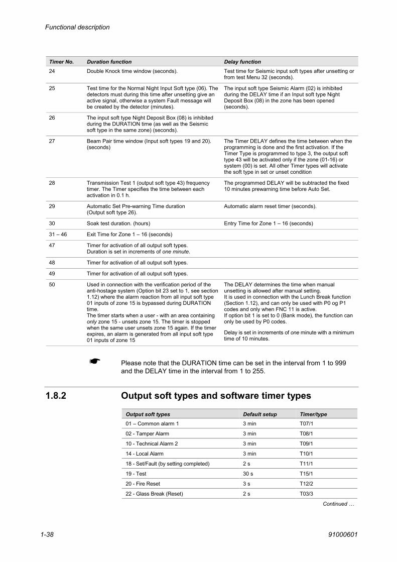
Functional description
910006011-38
Timer No. Duration function Delay function24 Double Knock time window (seconds). Test time for Seismic input soft types after unsetting or
from test Menu 32 (seconds).
25 Test time for the Normal Night Input Soft type (06). Thedetectors must during this time after unsetting give anactive signal, otherwise a system Fault message willbe created by the detector (minutes).
The input soft type Seismic Alarm (02) is inhibitedduring the DELAY time if an Input soft type NightDeposit Box (08) in the zone has been opened(seconds).
26 The input soft type Night Deposit Box (08) is inhibitedduring the DURATION time (as well as the Seismicsoft type in the same zone) (seconds).
27 Beam Pair time window (Input soft types 19 and 20).(seconds)
The Timer DELAY defines the time between when theprogramming is done and the first activation. If theTimer Type is programmed to type 3, the output softtype 43 will be activated only if the zone (01-16) orsystem (00) is set. All other Timer types will activatethe soft type in set or unset condition
28 Transmission Test 1 (output soft type 43) frequencytimer. The Timer specifies the time between eachactivation in 0.1 h.
The programmed DELAY will be subtracted the fixed10 minutes prewarning time before Auto Set.
29 Automatic Set Pre-warning Time duration(Output soft type 26).
Automatic alarm reset timer (seconds).
30 Soak test duration. (hours) Entry Time for Zone 1 – 16 (seconds)
31 – 46 Exit Time for Zone 1 – 16 (seconds)
47 Timer for activation of all output soft types.Duration is set in increments of one minute.
48 Timer for activation of all output soft types.
49 Timer for activation of all output soft types.
50 Used in connection with the verification period of theanti-hostage system (Option bit 23 set to 1, see section1.12) where the alarm reaction from all input soft type01 inputs of zone 15 is bypassed during DURATIONtime.The timer starts when a user - with an area containingonly zone 15 - unsets zone 15. The timer is stoppedwhen the same user unsets zone 15 again. If the timerexpires, an alarm is generated from all input soft type01 inputs of zone 15
The DELAY determines the time when manualunsetting is allowed after manual setting.It is used in connection with the Lunch Break function(Section 1.12), and can only be used with P0 og P1codes and only when FNC 11 is active.If option bit 1 is set to 0 (Bank mode), the function canonly be used by P0 codes.
Delay is set in increments of one minute with a minimumtime of 10 minutes.
Please note that the DURATION time can be set in the interval from 1 to 999and the DELAY time in the interval from 1 to 255.
1.8.2 Output soft types and software timer types
Output soft types Default setup Timer/type01 – Common alarm 1 3 min T07/1
02 - Tamper Alarm 3 min T08/1
10 - Technical Alarm 2 3 min T09/1
14 - Local Alarm 3 min T10/1
18 - Set/Fault (by setting completed) 2 s T11/1
19 - Test 30 s T15/1
20 - Fire Reset 3 s T12/2
22 - Glass Break (Reset) 2 s T03/3
Continued …

Functional description
91000601 1-39
Output soft types Default setup Timer/type26 - Auto-Set Prewarning 5 min T29/1
29 - Common Alarm 2 3 min T07/1
39 - Hold-up/Duress 1 min T14/1
43 - Transmission Test 1 ∞ T2/1 *
48 - CPU-Reset 2 s T11/1
*The Timer No. must be changed to another timer No. between 7 - 18 before using the soft type 43.
Name Default setup Timer/typeMains power drop-out detection time 250 ms Software
Mains power failure detection time 1 h T06/1
Mains power lamp flash 0.5 Hz Software
Battery presence test frequency 5 s Software
Battery presence test duration 25 ms Software
Battery load test frequency 24 h Software
Battery load test duration 15 s Software
Watch dog timer reset frequency <400 ms Software
I/O-Board input sample time 62.5 ms Software
S-ART input sample time 125 ms Software
Input circuit change detection time 250 ms Software
I/O-Board output refresh time 1 s Software
S-ART output refresh time 1 s Software
Normal auto-clear time 2 min. Software
Auto-clear time during test/programming 25/10 min. Software
Operating fault buzzer activation 0.5 s Software
Keypad blockade after log-in fault 5 min. Software
Log-out in alarm condition buzzing 15 s Software
Engineer code acceptance after alarm 2 min Software
Keypad lamp flash during lamp test 0.5 Hz Software
Keypad display flash during lamp test 0.5 Hz Software
Entry/Exit buzzing during zone test 5 s T04/1
Set/Fault activation by 1-2 isolations 5 s T05/4
Keypad buzzing during zone test 1 s Software
Status refresh time during input test 5 s Software
Double Knock time window 5 min. T24 DURATION
Double Knock 1 event detection time 10 s T24 DELAY
Soak test duration 7 days T30/1 DURATION
Auto Set pre-warning time duration 5 min. T29/1
Auto Alarm Reset time-delay 3 min. T30/1 DELAY
Exit time of zone 1 min. T31-46/1
Entry time of zone 1 min. T31-46/1

Functional description
910006011-40
Timer types
To describe the function of a timer, a timer type can be allocated to each timer No.Seven different timer types exist and can be used as required.
Timer type No. Description1 Normal function (output normally OFF)
2 Inverted function (output normally ON)
3 30 ms pulse width - only on I/O-board output address 001 to 016
4 Output alternating 0.5 Hz during time-duration
5 Like 4, but with inverted function (output normally ON)
6 Output alternating 0.25 Hz during time-duration
7 Like 6, but with inverted function (output normally ON).
See Chapter 3, Programming, for more information about the allocation oftimers/timer types to output soft types.

Functional description
91000601 1-41
1.9 Alarm functionsAlarm Functions makes it possible to activate an output depending on alarmsfrom specific input addresses and not only from a zone as the normal output softtypes.
In general, an Alarm Function can only be active when the input condition is inalarm, meaning that there must be an alarm message in the alarm display.However, the input types "Follow me" and "Only in log system fault" can activatean Alarm Function without creating an alarm message.See also Section 1.9.4 for information about Alarm Functions indicating that alldetectors or certain detectors are in normal condition.
1.9.1 IF - THEN expressionsNormally the large number of input and output soft types, each with individualcharacteristics, are more than adequate for creating the wanted input-outputreaction. Sometimes however, a special function not found as standard, isneeded. Such functions are often made by means of a small piece of hardwareor by interconnections between a number of relay outputs. In order to supplysome assistance in making "unforeseen" relations between input conditions andoutputs, some free programmable IF - THEN expressions (or alarm functions)are added as a supplement to the fixed input/output soft types.
In general the input and output fields of the expressions refer to physicaladdresses (not to soft types). The value of each field is either FALSE (0) orTRUE (1) corresponding to the input/output conditions PASSIVE or ACTIVE.The expressions are calculated according to the rules of Boolean Algebra, whichmeans that multiplications are made before additions.
Boolean Algebra: 1 + 1 * 0 = 1 + (1 * 0) = 1 (and not (1 + 1) * 0 = 0)
The operands used are: + (logical OR - selected by the - key)
* (logical AND - selected by the - key)
In terms of Thor expressions, it works like this:
Ex. 001 = 002 + 003 * 004
which is translated into the verbal description: IF input address 002 is active ORinput address 003 AND 004 are both active, THEN output 001 is active, ELSEoutput 001 is passive.
The number of expressions is 49 and each expression allows for a maximum of11 input fields and 1 output field. The first field displayed is the expression number851 to 899. The next 11 input fields are for standard input addresses. The value ofan input (true = active or false = passive) depends on the input soft type allocatedto this input address. The last field makes it possible to direct the expression to astandard output address (3 digits) and to allocate a timer to this output (2 digits).
No further programming of the output is needed to make it follow the value of theexpression. If, however, the output should be reset at logon to a keypad, the sameoutput address must be programmed with an Output Soft type 25 in Menu 48.

Functional description
910006011-42
If an input field is not filled-in or equal to 000, it is disregarded. The output fieldneeds not to be programmed if the expression is an input to another expression.Apart from the standard input addresses, some special inputs are allowed inorder to make larger calculations (one expression may be the input to another)or in order to take special conditions into account.
1.9.2 Alarm functions for local / transmission outputsIf the output address is programmed with an Output Soft type 25 in Menu 48,then this output is reset at logon to a keypad within the zone (like a siren output).The Output Soft type 25 must not be programmed with zone 00 but only anotherzone No. included in the code/area that must reset the output.
If no Output Soft type is programmed to the output address, then the output willwork as a Transmission output which are reset when the inputs to the equationare FALSE (all input messages reset from the display buffer).
1.9.3 Auto alarm reset of output alarm functionsIf the Timer allocation to the output of an expression is Timer No. 23, then thenormal reaction of this output is turned around, which means that the output isactivated, when the expression becomes TRUE. When the expression comesfalse, the output is reset after the time specified in the DURATION part of theTimer No. 23 (see the example below for output address 400). This feature isprimarily introduced in order to establish the Auto Alarm Reset function, whichalso requires the special operand 029 - ACTIVE to be used in the input field infront of each input address in order to have the proper reaction.
Example: 851 = 029 * 100 + 029 * 101 + ...... = 40023
Important: If an address Input soft type 04 (Entry/Exit detector) is used in anAlarm Function, the address must always be AND'ed with the special Operand025 (Detector set). If this is not done, the Alarm Function output will be re-activated during the unset period (entry time). See the example below:
Example: 851 = 029*400*025*400 + .......=40023
1.9.4 Alarm function without alarm input conditionAlthough an Alarm Function only can be active when the input condition is inalarm, it is possible to create Alarm Functions reacting on an output without thedetector to be in alarm condition.This means that you can make an output, which can indicate if all or certaindetectors are in normal condition, before you try to set the zone by for examplea key-switch.
This is done by the operands ACTIVE (29) and PASSIVE (30) which will take inthe real condition of the detector alarm contact in Set or Unset condition. If thisOperand is not used the Alarm Function will work as normal meaning that itmust be in Alarm condition.
The SET (25) and UNSET (26) operands can also be used without having theinput to be in Alarm condition first.

Functional description
91000601 1-43
1.9.5 Special operandsThe set/unset condition of the input address to the right in this part of theexpression must be SET. Must be used together with * (logical AND) and worksfor standard input addresses and Input soft types 01, 02, 04, 06, 08, 19 and 20only.
The set/unset condition of the input address to the right in this part of theexpression must be UNSET. Must be used together with * (logical AND) andworks for standard input addresses and Input soft types 01, 02, 04, 06, 08, 19and 20 only.
Inverting "operand". Used to invert the value of the input address to the right -027 * xxx corresponds to xxx passive = TRUE. Works for standard as well asspecial input addresses.
The alarm condition of the input address to the right in this part of theexpression must be TAMPER (the default set-up is the alarm input of the S-ART). Must be used together with * (logical AND) and works for standard inputaddresses only.
The actual input condition of the input address to the right in this part of theexpression must be ACTIVE (the default set-up does not distinguish betweenactive and passive). Must be used together with * (logical AND) and works forstandard input addresses only.
The actual input condition of the input address to the right in this part of theexpression must be PASSIVE (the default set-up does not distinguish betweenactive and passive). Must be used together with * (logical AND) and works forstandard input addresses only.
1.9.6 Standard input addresses
Loop Inputs of the CU-30
Vault Controller
Video Loss Camera 1 – 5
Bus Device Alarm/Fault Messages, address 01 – 31
Video Loss Camera 6 – 8
Minitel Fault Messages
Thor Intrusion Internal Fault Messages
S-ART inputs
S-ART inputs
S-ART inputs
S-ART inputs
Bus Device Tamper/Fault Messages, address 00 – 31
Printer
025
026
027
028
029
030
001 – 002
017 – 024
025 – 029
031 – 061
070 – 072
076 – 080
081 – 092
100 – 130
200 – 230
300 – 330
400 – 430
500 – 531
- 532

Functional description
910006011-44
1.9.7 Standard output addressesOutputs of the CU-30S-ART outputsS-ART outputsS-ART outputsS-ART outputsMinitel outputs
1.9.8 Special input addressesPseudo input addresses describing the hold-up alarm condition of the system(zone 00) and zone 01 to 16. TRUE if one or more messages of this kind arefound within the zone. FALSE when all such messages have been reset.
Pseudo input addresses describing the intrusion alarm condition of the system(zone 00) and zone 01 to 16. TRUE if one or more messages of this kind arefound within the zone. FALSE when all such messages have been reset.
Local alarm from Input Soft type 03 in the unset condition and tamper alarm nomatter the set/unset condition do not affect these input addresses.
Pseudo input addresses describing the system fault condition of the system(zone 00) and zone 01 to 16. TRUE if one or more messages of this kind arefound within the zone. FALSE when all such messages have been reset.
System fault from Input Soft type 16 does not affect these input addresses.
Pseudo input addresses describing the tamper alarm condition of the system(zone 00) and zone 01 to 16. TRUE if one or more messages of this kind arefound within the zone. FALSE when all such messages have been reset.
Pseudo input addresses describing the technical alarm condition of the system(zone 00) and zone 01 to 16. TRUE if one or more messages of this kind arefound within the zone. FALSE when all such messages have been reset.
Local technical alarm from Input Soft type 11 in the unset condition does notaffect these input addresses.
Pseudo input addresses describing the isolation condition of the system (zone00) and zone 01 to 16. TRUE if one or more messages of this kind are foundwithin the zone. FALSE when all such messages have been reset.
Pseudo input addresses describing the fire alarm condition of the system (zone00) and zone 01 to 16. TRUE if one or more messages of this kind are foundwithin the zone. FALSE when all such messages have been reset.
Pseudo input addresses describing the set/unset condition of the zones 01 to 16,i.e. TRUE when zone is SET or PARTIALLY SET, FALSE when zone is UNSET.
Pseudo input addresses describing the set/unset condition of the areas, i.e. 600is TRUE when all areas used are set (SYSTEM SET - isolation may be present),while 601 to 850 represent the corresponding areas 001 to 250 - TRUE whenthe area is physically or logically SET, FALSE when the area is PARTIALLY SETor UNSET.
001 – 008100 – 129200 – 229300 – 329400 – 429900 – 999
140 – 156
160 – 176
Note!
180 – 196
Note!
240 – 256
260 – 276
Note!
280 – 296
340 – 356
361 – 376
600 – 850

Functional description
91000601 1-45
IF-THEN Expression Buffers. May be directed to standard output addresses andat the same time be inputs to other expressions.
If you are not using the operands ACTIVE (29) and PASSIVE (30), the functionswill remain as outlined in the table below. However, if the operands 29 or 30 isused, the function will change accordingly. See Section 1.9.4 for moreinformation.
Conditions to become:Input type and name “True” “False”01 - Normal Night Alarm Message Alarm Reset
02 - Seismic Alarm Alarm Message Alarm Reset
03 - 24h (Fire door - related to OTYP 14) Alarm Message Alarm Reset
04 - Entry Route (With timer) Alarm Message Alarm Reset
05 - Bypass Unit Active Passive
06 - Normal Night 2 h (Test) Alarm Message Alarm Reset
07 - Tamper Alarm Message Alarm Reset
08 - Night Deposit Box Alarm Message Alarm Reset
09 - Hold-up 1 (blocks bells) Alarm Message Alarm Reset
10 - Technical/Film counter Alarm Message Alarm Reset
11 - Technical 1 (local) Alarm Message Alarm Reset
12 - Technical 2 (external) Alarm Message Alarm Reset
13 - Sys. Fault 1 (normal trouble) Fault Message Fault Reset
14 - Sys. Fault 2 (automatic reset) Active Passive
15 - Sys. Fault 3 (engineer reset) Fault Message Fault Reset
16 - Sys. Fault 4 (just event-log) Active Passive
17 - Key Storage box Alarm Message Alarm Reset
18 - Fire Alarm Alarm Message Alarm Reset
19 - Beam Pair 1 (With timer) Alarm Message Alarm Reset
20 - Beam Pair 2 (With timer) Alarm Message Alarm Reset
21 - Shock Count Alarm Message Alarm Reset
22 - Hold-up 2 (blocks bells) Alarm Message Alarm Reset
23 - Local perimeter detection Alarm Message Alarm Reset
24 - Follow Me Active Passive
25 - Set/Unset Zone Pulse Active Passive
26 - Set/Unset Zone Level Active Passive
27 - Set/Unset Area Pulse (Area 001-016) Active Passive
28 - Set/Unset Area Level (Area 001-016) Active Passive
29 - Alarm reset Active Passive
30 – 24 h Seismic Alarm Alarm Message Alarm Reset
31 – 24 h Night Deposit Box Alarm Message Alarm Reset
32 - Vindicator lock Active Passive
33 - High Security – entry door Alarm Message Alarm Reset
34 - Anti-mask Alarm Message Alarm Reset
35 - Primary Transmission Fault Active Passive
851 – 899
Note

Functional description
910006011-46
An Alarm Message is a message in the alarm list, Menu 11, resulting from anactivation of the alarm input of the S-ART (not the tamper input).
An Alarm Reset is an alarm message manually deleted from the alarm list.
A Fault Message means an activation of the alarm input of the S-ART unit(not the tamper input) resulting in a message in the fault list of menu 12.
A Fault Reset is a fault message manually deleted from the fault list.
Active or Passive condition describe the actual condition of the alarm input ofthe S-ART.
Typical time from alarm detection to output activation is 1 to 3 s.
Alarm Message
Alarm Reset
Fault Message
Fault Reset
Active or Passive
Reaction time

Functional description
91000601 1-47
1.10 Single-site and multi-subsite systemBy use of the option bit 14, it is possible to run the software in two differentmodes, a multi sub-site mode (distributed system) or single site mode(integrated system).
The purpose of the multi sub-site mode is to divide the Thor central unit intoseveral sub-systems where each subsystem has one or more Remote keypads tooperate the part belonging to the subsystem. In this mode alarms etc. are onlyshown on the Remote keypads belonging to the zones from where the alarms arecoming. The user does not know what is going on the other sub-site systems. Thiscan be used for example in sites with several companies in the same building.
In the single site mode all alarms etc. can be seen by all codes and from allRemote keypads, but still the reset of alarms, disarming of other zones etc. aredepending on the zone mask dependency.
In the following tables the user zone mask dependency of user (area) andoperating panel when operating a distributed or an integrated system is shown.
Two columns for each type of system are shown. The are labelled User andRKP, respectively. When a "yes" is shown in the User column, it means that thisfunction or menu is using the area/zone mask to display or to allow the function.On the contrary, when a "no" is written, the menu or function works global notdepending on the area/zone mask.
The RKPs can be defined to work on zones also (See Chapter 3, Programming).In the RKP column, a "yes" means that the function or menu is using theRKP/zone mask. Opposite when a "no" is written, it means that the menu orfunction works global with no RKP/zone mask dependency.
Multi-subsite system Single site systemUser RKP User RKP Remarks
Menu 10 Code-Area status - area display - area setting - area unsetting - autoset area unset - zone display - zone setting - zone unsetting - auto set zone unset - detector isolation
yesyesyesyesyesyesyesyesyes
noyesyesyesnonononoyes
yesyesyesyesnonononoyes
noyesyesyesnonononoyes
All codesAll codesAll codesP2, P4 codes onlyAll codesAll codesAll codesP2, P4 code onlyP0-P1 max. 2
Menu 11 Alarm list - alarm display - intrusion alarm reset - tamper alarm reset - hold-up alarm reset - technical alarm reset - fire alarm reset
yesyesyesyesyesyes
nononononono
noyesyesyesyesyes
nononononono
All codesAll codesP2-P4 codes onlyAll codesAll codesAll codes
Menu 12 System Fault List - system fault display - battery fault reset - 1h mains fault reset - system fault (3) reset
yesyesyesyes
nononono
noyesyesyes
nononono
All codesAll codesAll codesP3-P4 codes only
Menu 13 Isolations List - detector display yes no no no All codes
Continued …

Functional description
910006011-48
Multi-subsite system Single site systemUser RKP User RKP Remarks
Menu 21 Area Status - area display - area setting - area unsetting
nonoyes
yesyesyes
nonoyes
noyesyes
All codesAll codesAll codes
Menu 22 Zone Status - zone display - zone setting - zone unsetting
nonoyes
yesyesyes
nonoyes
yesyesyes
All codesAll codesAll codes
Menu 23 Detector Status - detector display - detector setting - detector unsetting - detector isolation
yesyesyesyes
yesyesyesyes
yesyesyesyes
yesyesyesyes
All codesAll codesAll codesAll codes
Menu 25 Event-Log - log display no no no no P1 – P4 codes only
Menu 26 Print Event-Log - log print no no no no P1 – P4 codes only
Menu 27 Print Status - status print no no no no P1 – P4 codes only
Menu 28 Print Set-up - set-up printing no no no no P2, P4 codes only
Menu 29 Alarm Counter - counter display no no no no P2, P4 codes only
Menu 31 Lamp Test - lamp and display test no no no no All codes
Menu 32 Walk test - test output activation yes yes yes yes P1 – P4 codes only
Menu 33 Battery Test - battery load test no no no no P1 – P4 codes only
Menu 34 Zone Test - semi-automatic test yes yes yes yes P1 – P4 codes only
Menu 35 Detector Test - individual input test no no no no P4 codes only
Menu 36 Output Test - individual output test no no no no P2, P4 codes only
Menu 37 Printer Test - test print-out no yes no yes P1 – P4 codes only
Menu 38 Bell Test - bell output activation no no no no P1 – P4 codes only
Menu 41 Date and Time - correction no no no no P1 – P4 codes only
Menu 42 Change of Code - correction yes no yes no P1 – P4 codes only
Menu 43 to 54 - programming no no no no P4 codes only (Note 1)
Menu 50 Allow Service - allow service code - set in service mode - reset all alarm/fault
nonono
nonono
nonono
nonono
P1 – P2 codes onlyP4 codes onlyP1 – P4 codes only
Menu 51 End Service Mode - disable service code no no no no All codes
Note 1: Requires a printer connected to the Control unit.

Functional description
91000601 1-49
1.11 Auto alarm resetThe purpose of automatic alarm reset is to passivate the alarm outputs andprepare the installation for detecting another alarm condition without the need ofhuman interference. Not only the acoustical indicators are affected, also thetransmission outputs are reset to let the central alarm station personnel decidewhether the alarm condition is a "faulty one" or a condition requiring immediateaction (by repeated alarm transmissions).
Automatic alarm reset is performed within each zone by means of individualzone timers, but using a time set-up common to all zones. When an alarmcondition within the zone is detected, the timer of this zone is started. If anotheralarm condition of a different detector within the same zone takes place beforetime-out, the timer is restarted.
At time-out, the actual input condition of all "auto alarm reset type" detectorswithin the zone, which are elements of the alarm list, are checked. In case theinput condition of just one detector is ACTIVE, the timer is restarted and thecheck performed at next time-out and so forth. When the input condition of allsuch detectors are QUIET, all outputs within the zone, affected by automaticalarm reset, are reset (if not already reset by the normal output timer) and thealarm panel is prepared for a new alarm detection - also from detectors alreadylisted in the alarm list, which can only be reset by the user.
Fig. 1.9 Auto Alarm Reset signal diagram.

Functional description
910006011-50
1.11.1 Input/output soft types affected by auto alarm resetThe table below lists the input and output soft types affected by an Auto Alarm Reset.
Input soft types
Input type 01 – Normal nightInput type 02 – Seismic alarmInput type 03 – 24h (Fire door)Input type 04 - Entry routeInput type 05 – Bypass unitInput type 06 – Normal night 2 hInput type 07 – TamperInput type 08 –Night deposit boxInput type 09 – Hold-up (only with option bit 3)Input type 19 – Beam pair 1Input type 20 – Beam pair 2Input type 21 – Shock countInput type 23 – Local Perimeter detectionInput type 30 – 24 h seismicInput type 31 - Night deposit box 2Input type 33 – High security entry doorInput type 34 – Antimask
Output soft types
Output type 01 - Common alarm 1Output type 02 - Tamper alarmOutput type 04 – Seismic alarmOutput type 07 – Hold-up (only with option bit 3)Output type 14 – Local alarmOutput type 23 – Perimeter 1st detectorOutput type 27 - Perimeter 2nd detectorOutput type 29 - Common alarm 2Output type 33 - IntrusionOutput type 34 - TamperOutput type 36 – Seismic alarm
Timer T30 DELAY is used for common Auto Alarm Reset time set-up whereDELAY can be set in the range 000 to 250 s. If DELAY is set to 254 s, the autoalarm reset function is disabled.

Functional description
91000601 1-51
1.12 Anti-hostage systemThe anti-hostage system is a way to prevent taking hostages when the bankpersonnel meet in the morning by showing alarms or unsetting/unset status onan indicator box with three LEDs visible from the outside of the bank.
The three LEDs - green, orange and red - on the indicator box have thefollowing meaning:
GO Green LED lit means that the unsetting procedure has been completedsuccessfully; you may enter the bank.
WAIT Orange LED lit means that the unsetting procedure is in progress buthas not yet been completed; you must wait for permission to enter thebank.
STOP Red LED lit means that an alarm condition is present; it is not permittedto enter the bank.
The anti-hostage system allows an external alarm to be generated in case ofassaults on persons that opens the bank in the morning.If a certain procedure is not followed or a timer expires while unsetting theintrusion system, an external alarm will be generated.The anti-hostage system is allocated to a logical area containing only a singlezone (anti-hostage zone) containing all PIR detectors of the anti-hostage system
In addition to this, special functions such as lunch timer, delay of autosetting,etc., are available
The anti-hostage system comprises a number ofinfrared (PIR) detectors inaddition to the indicator box located so that it is visible outside the bank.
Usually the intrusion system will consist of at least two areas: a peripheral areaand a main area.Both areas are controlled by by week programs that will ensure that they areautomatically set as scheduled and that they can be manually unset on thescheduled dates and times.
Please note that the anti-hostage functions and associated function are enabledonly when option bit 23 is set to 1. See page 4-35.
Introduction

Functional description
910006011-52
1.12.1 Anti-hostage system operationWhen the first person arrives, the system is set and all LEDs on the box at areunder normal conditions turned off. If an alarm condition is present, the red LEDis lit and it is not permitted to enter the bank to unset the intrusion system.
To unset the system when all LEDs are turned off, the person must enter hispin-code on the 95T RKP and press the - key. The orange LED on the boxwill be turned on, the alarm reaction of the PIR dectors will be bypassed (i. e.temporarily disabled) and a verification period timer is started. The lit orange LEDindicates that persons arriving to the bank later, must wait for a permission toenter the bank.
The first person must then walk a tour in the bank within the verification period toactivate all PIR detectors of the anti-hostage system. When the tour is finished, theperson returns to the 95T RKP and enters the same pin code again and presses the
- key. If all PIR detectors of the anti-hostage system were activated during thetour, the verification period timer is stopped, the orange LED is turned off, the systemis unset, and the green LED is turned on. The lit green LED indicates that personsarriving to the bank have permission to enter the bank immediately.
In case of a hold-up, the person held may limit his tour in the bank to ensure thatnot all PIR detectors are activated. After this, the person returns to the 95T RKPand enters his pin-code again. This will put all unactivated PIR detectors into alarmcondition, generate an external alarm and turn the red LED on.
If the verification period timer - started the first time the - key was pressed -expires before the pin-code is entered again and the - key is pressed thesecond time, all PIR detectors will go into alarm condition, generate an externalalarm and turn the red LED on.
After the unsetting, the system may be manually set again for example duringthe lunch break.A timer controls the time when a manual unsetting is allowed after a manualsetting has been performed. The time can be set in increments of one minute;the minimum time that can be set is 10 minutes. The function is controlled bythe week program function FNC 11.
When the system has to be set, the person will enter his personal pin-code andpress the - key. The system is then set and all LEDs of the indicator box areturned off.
After the system has been set after the normal working hours, it will remain setuntil the mnual unsetting is performed the following morning within the periodwhere manual unsetting is allowed.
However, a guard may make his usual round in the bank using his alarm patrolcode (P3) that should be programmed to the logical area containing the anti-hostage zone.
The procedure for the unsetting and setting the system is the same as thatpreviously described and the anti-hostage system will provide identical reactionsto identical circumstances as described above.
It is not possible to use the alarm patrol code in weekends and on holidays. Onlyday types 1 to 5 will allow the alarm patrol code to be used.
System status
Unsetting thesystem
Hold-up
After unsetting ofthe system
Setting the system
After setting of thesystem

Functional description
91000601 1-53
1.12.2 Functional descriptionThe anti-hostage zone is defined to be zone 15. In this zone, the alarm reactionfor the which are programmed for the zone can be bypassed (temporarilydisabled) by users with a priority 0 code or a priority 3 code (Alarm patrol code)to an area that contains only zone 15.All inputs (from PIR detectors) programmmed with input soft type 01 andbelonging to zone 15 can be put into the bypass mode where an activation of theinput will be stored.
The zone is put into this bypass mode the first time a user enters his pin-codeon the 95T RKP and presses the - key. At the same time a verification periodtimer (Timer 50 – duration – see Section 1.8.1.) is started and the orange LEDon the box will be turned on.The orange LED is controlled by a output soft type 50 (Section 1.6.2). The outputsoft type is active while the zone is in the bypass mode The output soft type mustbe programmed in zone 15 or as a common type (Zone 0) in order to work.
The user must then walk a tour in the bank within this verification period toactivate all PIR detectors of the anti-hostage system. When the tour is finished,the user returns to the 95T RKP and enters the same pin code again andpresses the - key.If all PIR detectors of the anti-hostage system were activated during the tour, theorange LED is turned off, the system is unset, and the green LED is turned on.The green LED can be controlled by a normal zone set (inverted) output soft typeor an alarm function, where timer 47 can be used for the activation. The timer 47duration is set in increments of one minute. See Section 1.8.1.
If not all PIR detectors of the zone were activated during the tour or theverification period timer expires, the entry of the pin-code again followed by thepressing of the - key will put all PIR detectors into alarm condition, generate anexternal alarm and turn the red LED on.The red LED is controlled by a normal local alarm output soft type.
The areas are controlled by automatic set/unset week programs that ensuresthat the areas are set and that they are allowed to be unset on the scheduleddate and times.
An automatic set/unset week program controls when it is allowed to manuallyunset the area. It will normally not be allowable to unset the area duringnighttime but only during daytime (after lunch break).When the area is automatically unset, it is allowable to manually set the area.If during daytime, the peripheral area is set (at lunch break), it is not allowed tounset the area before after a predefined (programmable) time.
The main area is also controlled by an automatic set/unset week program. Theweek program will not unset the area but will give a user access to unset thearea manually. If the area is not unset within the allowed period, it will not bepossible to manually unset the area that day.If the main area is not manually unset at the end of the period in which it may bemanually unset, the peripheral area must be set automatically.
If during daytime, the main area is set (at lunch break), it is not allowed to unset thearea before after a programmable time of minimum 10 minutes.In the evening, if some of the personnel have to work late, it is possible to delaythe automatic setting with up to one hour. If the setting of the main area is
Anti-hostage zone
Peripheral areaand main area
Peripheral area
Main area

Functional description
910006011-54
delayed, then the automatic setting of the peripheral area wil be delayed alsountil the setting of the main area takes place.
There is some interdependence between the functions of the automaticset/unset week programs of the peripheral area and main area.
In general the interdependence is established by pairing the areas by incrementingthe area number by one. This means that if the main area is area 1 and theperipheral area is area 2, the required interdependence can be established. Thesame interdependence can also be established by for example area 2 and area 3and by area 8 and area 1, etc.
All user dependent rights for setting and unsetting are only valid for P0 and P1codes, when the CU is operating in bank mode. If not operating in bank mode, itis only valid for P0 codes.The normal function of P0 and P1 codes is preserved where the unsetting rightsare controlled by week programs.
The week program function FNC 10 will allow manual unsetting at the start ofthe period. If the area has not been manually unset at the end of the period, thearea + 1 is set automatically. This means that if the function is programmed forarea 1, then area 2 will be set automatically; if the function is programmmed forarea 8, then area 1 will be set. See also Section 3.7.1.
A timer controls the time that must pass after a manual setting before a manualunsetting is allowed. Timer 50 – delay is used for setting this time (Lunch timer).
This function is only valid for P0 and P1 codes, when the CU is operating inbank mode. If not operating in bank mode (option bit 1 is set to 0), it is only validfor P0 codes.The function is only enabled when the week program period with FNC 11 isstarted; it is disabled when the first automatic setting is activated.
Week program function FNC 11 will allow manual setting and unsetting at thestart of the period, but only if the area is unset when the period starts. Thisfunction is used for enabling the lunch timer function described above. See alsoSection 3.7.1.
If the automatic setting for the week program functions FNC 1 to FNC 8 isdelayed, the automatic setting for the area+1 is delayed also.When the area, where the automatic setting was delayed, is set, the area+1 isset too.
Week programinterdependence
Week program FNC 10
Lunch timer
Week program FNC 11
Delay of automaticsetting
Installation
91000601 2-1
InstallationInstallationInstallationInstallationThis chapter provides the information needed to install the various componentsof an intrusion system.
The chapter contains the following sections:
Section Page
Noise emmission prevention 2-2
90T CU-30 and 95T CU-30 central unit 2-3
95T CU-30-24V Central unit 2-12
S-ARTs 2-18
Remote keypads 2-37
General purpose Interface 95T GPI COM 2-39
GPI BR Bridge 2-49
GPI BRM/DLM Direct line modem interface 2-50
GPI DLC Bus amplifier 2-52
RS-485 bus connections 2-53
Cable length and dimension 2-54
Current consumption 2-55
Introduction
This chapter

Installation
910006012-2
2.1 Noise emmission preventionTo prevent noise emmission and to comply with EN 50081-1, it is important thatthe installation instructions of this manual are followed.
In addition to this, all cables leaving the Thor Central Unit box must be protected bymeans of ferrite cores (except the mains power cable). This applies also to cablesfrom the 95T I/O-board (Section 2.2.4 and 2.3.2) and an internally mounted99T IPI interface.For this purpose, three ferrite clamp cores are supplied with the Thor CentralUnits 90T CU-30, 95T CU-30, and 95T CU-30-24V.
Fig. 2.1 Example of a ferrite clamp core (side and top view, scale 1:1 ) as delivered and top view ofa ferrite clamp core clipped around two cables.
The ferrite clamp cores simply clip around the cables enabling the cores to beinstalled after the cables have been connected to the ThorGuard Central UnitCPU-board, a 95T I/O-board, or a 99T IPI interface.
Each ferrite clamp core may accomodate two cables only and these cables mustbe connected to terminals on the same side of the CPU-board.
The three ferrite clamp cores supplied will suffice for the majority of installations.However, if more are needed, they are available from HI SEC Internationalunder the stock No. 125034.
Introduction
Protection needed
Installing the ferritecores

Installation
91000601 2-3
2.2 90T CU-30 and 95T CU-30 central unitThe Thor Intruder System central unit CU-30 can be delivered in two cabinettypes. The CPU board and the software functions are the same for both types.
!!!! Please note that the 90T CU-30 and the 95T CU-30 both are 12 V systems
2.2.1 Lay-out of the 90T CU-30 central unitThe 90T CU-30 can control one S-ART bus meaning max. 30 S-ARTs. Thecabinet has space for one 12 V, 6.5 Ah accumulator.
Fig. 2.1 90T CU-30 central unit layout. All dimensions is in mm.
2
External dimensions H x W x D: 317 x 241 x 95 mm
241
40
237
40
317
22197
22
12 V, 6.5 Ah accumulator

Installation
910006012-4
2.2.2 Lay-out of the 95T CU-30 central unitThe 95T CU-30 can control one S-ART bus in the standard version but canaccommodate the optional 95T I/O board that can control three additional S-ARTbusses, i.e. control of a maximum of 4 x 30 S-ARTs. The cabinet has space forone 12V, 24Ah accumulator.
Fig. 2.2 95T CU-30 central unit layout. Optional 95T I/O board mounted. All dimensions is in mm.
2
External dimensions H x W x D: 525 x 375 x 140 mm
375
525
40
445
40
275 5050
12 V, 24 Ah accumulator

Installation
91000601 2-5
2.2.3 95T CUB-30 CPU boardThe 95T CUB-30 CPU board is used in both the 90T CU-30 and the 95T CU-30central units.
Fig. 2.3 95T CUB-30 CPU board layout.
2
!!!! Jumper J3 is used during factory tests. It must not be removed .
Position Application RemarksSW3/1 On Central unit address 00,
COM address 01Please note that 90T CU-30 uses twoaddresses
SW3/1 Off Central unit address 01,COM address 02
Please note that 90T CU-30 uses twoaddresses
SW3/2 RS-232 COM definition See RS-232 COM port , page 2-7
SW3/3 RS-232 COM definition See RS-232 COM port , page 2-7
SW3/4 On No RS-485 encryption -
SW3/4 Off RS-485 encryption selected -
Lay-out
Switch SW3settings
S-ART terminals(Addr. 100-129)
RS-485 terminals
RS-232 terminalsRelay terminals
Output 5-7 terminals
Output 1-4 terminals
Input 1-2 terminals
SW3 – Address andapplication switch
J2 – RAM battery
J1 – RS 485end-of-line resistor
J5 – 12 V/24 V setting ofoutput voltage on S-ARTand RS 485 connectors
Battery terminals
COM EPROM
Fuse testsocket
Battery loadtest terminals
Battery fuses
OP3 fuse test LED
S-ART bus DC fuse
OP2
Main CPU EPROM
RS-485 fuse
J6 – CPU reset
OP1
Connector for flat-cableto 95T I/O
AC powerterminals
Tamperswitch
J3 – Factory test only

Installation
910006012-6
The 95T CUB-30 CPU-board is equipped with a number of jumpers for variouspurposes. These are described in the table below:
Jumper DescriptionJ1 Connects the RS 485 end-of-line resistor when mounted
J2 Disconnects RAM battery when removed.
J3 Used during factory tests. Must not be removed.
J5 When mounted on the pins labelled ”12V”, the output voltage on S-ART and RS 485screw terminal connectors is supplied from the internal 12 V DC supply. Whenmounted on the pins labelled ”24V”, the output voltage on S-ART and RS 485connectors should be supplied from an external power supply (12 V DC or 24 V DC).
J6 Resets CPU when mounted.
Fig. 2.4 Connections to S-ART terminals.
Fig. 2.5 Connections to Output 1 - 4 terminals and Output 5 - 7 terminals.
Fig. 2.6 Connections to Input 1 - 2 terminals.
Jumpers
Connection toS-ART terminals
Connections tooutput terminals
Connections toinput terminals

Installation
91000601 2-7
Fig. 2.7 Example of connections to Relay terminals.
! " !
# $ % & $ ' ( ! $ $ ( %
! " !
# $ % & $ ' ( ! $ $ ( %
) " % * & $ + ' + + , " ! % - . ) " % * & $ + ' + + , " ! % - .
The CPU-board has an on-board tamper contact. This tamper contact is usingthe input address 500 or 501 depending on the address selected on the RS-485bus (00 or 01) (see CPU-board switch settings).
RS-232 COM port
The RS-232 serial port can have different functions depending on the switchsetting of switch SW3, 2 and 3. The serial port can be used as PC interface, asprinter interface, as modem and X28 interface, as an interface to the TCP/IPinterface 99T IPI, and as an interface to a SECOM alarm transmitter.
Switch position for printer application: SW3/2 = OFF, SW3/3 = OFF.
The printer can be used in two different ways: Intrusion or Access. Default theprinter interface will be an Intrusion printer. To change this the SW3/2 must bechanged with DC connected as follows:
SW3/2 OFF --> ON: Access printerSW3/2 ON --> OFF: Intrusion printer
After changing SW3/2 for selecting printer type, power must be removed from thecentral unit and the SW3/2 must be put back to the default printer setting (SW3/2and 3/3 both OFF). When the power is put back the interface will start up in themode (intrusion or access) last selected when changing the switch with power on.
For the connection diagram, please refer to the table on page 2-41 about theconnection of a serial printer.
Switch position for PC interface application:
SW3/2 ONSW3/3 ON
For the connection diagram, please refer to Section 2.6.1 on page 2-43.
Switch position for modem/x28 application:
SW3/2 ONSW3/3 OFF
Connections torelay terminals
Tamper switch
Printer interfaceapplication
PC Interfaceapplication
Modem/X28 Interfaceapplication

Installation
910006012-8
The modem interface can be used in two different ways: Hayes modem or X28Pad interface. Default the interface will be a Hayes modem interface. To changethis the SW3/2 must be changed with DC connected as follows:
SW3/2 OFF --> ON: X28SW3/2 ON --> OFF: Hayes
After changing SW3/2 for selecting modem/x28 type power must be removedfrom the central unit and the SW3/2 must be put back to the default Modem/X28setting (SW3/2=ON, SW3/2=OFF). When the power is put back the interface willstart up in the mode (Hayes or X28) last selected when changing the switch withpower on.
For the connection diagram, please refer to Section 2.6.2 on page 2-44.
The 99T IPI is a TCP/IP interface that can be mounted in both the 90T CU-30and the 95T CU-30. See the Installation instructions, 99T IPI, ref. No 94000401(English version) for more information.
Switch position for SECOM transmitter application: SW3/2 = OFF, SW3/3 = ON.
For further information concerning the SECOM transmitter, please refer to theFrench version of this manual.
LED indicators
The following LED indicators can be used to check if the CPU-board is runningunder normal conditions:
OP1: Indicates that the RS-485 bus communication is OK. The LED musttoggle with a frequency depending of the traffic on the bus. If no panelsare logged on to, the LED will flash every 1/2 minute when the clock in thedisplays is updated. If one or more panels are logged on to the LED willflash every time a display picture is changed. See Fig. 2.3 for position.
OP2: Indicates that the S-ART communication is OK and must give a flickeringlight or nearly steady light. See Fig. 2.3 for position.
OP3: The LED OP3 will indicate fuse OK when lit if the fuse to test is inserted inthe test socket next to the LED. See Fig. 2.3 for position.
Fuses
F1, F2: T5A, fuses in Bat+ and Bat-.
F3: T500mA, fuse for the S-ART bus DC output.
F4: T500mA, fuse for DC output for the on-board outputs 1 - 4.
F5: T500mA, fuse for DC output for the on-board outputs 5 - 7.
F6: T500mA, fuse for DC output for the RS-485 bus.
TCP/IP
SECOM transmitterinterface application

Installation
91000601 2-9
2.2.4 Expansion board 95T I/OThe 95T I/O board gives the possibility to add 3 more S-ART buses when usedin connection with the 95T CU-30. The extra S-ART buses are using theaddresses 200 - 229, 300 - 329 and 400 - 429.
Moreover, the 95T I/O board is equipped with additional screw terminals forconnection of an external power supply to allow for external supply (24V DC or12 V DC) on the S-ART and RS-485 buses.
Fig. 2.8 The connector, screw terminals and fuses of the 95T I/O board.
2 : #
The 95T I/O board can be mounted above the CPU-board on the stays in the95T CU-30 cabinet.A flat-cable delivered together with the 95T I/O board must be installed betweenthe CPU-board and the I/O-board.
Fig. 2.9 Power supply and S-ART bus connections to the 95T I/O board.
2
Please note that the 95T I/O board cannot be mounted in the 90T CU-30 cabinet.
Layout of the95T I/O board
Connections to the95T I/O board
S-ART line(Addr. 400-429)
S-ART line(Addr. 300-329)
S-ART line(Addr. 200-229)
Connector for flat-cableto CPU-board
Connections toexternal power supply
L+L-
0V
24V
12V
BM
PM
BT0 0 V
BT1
S-ART line(Addr. 200-229)
The connections are similarfor the S-ART lineswith the addresses 300-329and 400- 429

Installation
910006012-10
If you want to supply power to the S-ART and RS 485 screw terminal connectorsfor operation of the units on the two buses, an external power supply such as95T PS 24/3.8 (24 V DC) or 90T PS (24 V DC – available as spare part only)can be used.
The connections between the power supply and the 95T I/O board are shown inFig. 2.10 and Fig. 2.11 below.
!!!! Remember to mount the jumper J5 of the 95T CUB-30 CPU board on the pinslabelled ”24V”, to supply the external power to the S-ART bus and RS-485connectors.
Fig. 2.10 24 V DC supply from an external power supply.
2 2
/
0//123/
42#22
25467/1182#
/515//122
/#272/
/124292:2
Fig. 2.11 Connection of external power supply 95T PS 24/3.8.
:
External powersupply
External power supplyconnections
Jumper J5
95T I/O board 95T PS
95T CUB-30CPU-board
To battery
Pin16
Pin15
Pin14
Pin13BT1
BT0PM
BM24V
GND
95T I/O board 95T PS board

Installation
91000601 2-11
2.2.5 Power supply and battery
!!!! Please note that the CU-30 power supply is a 12V DC power supply.
The CU-30 power supply is included on the CPU board, only the transformer isplaced below the board. The CU-30 power supply is used in both the 90T CU-30and 95T CU-30 cabinets.
Parameter Value or descriptionInput voltage: 230 V AC +/- 15%
Fuse: S 0.4 A (slow)
Load: Max. 0.5 A on all output terminals
Max. battery charging current: 1 A
Charging voltage: 13.1 V DC +/- 0.1 V at 0 0C13.8 V DC +/- 0.1 V at 200C14.2 V DC +/- 0.1 V at 500C
Voltage drop from battery supply toterminals:
1.5 V
Max. battery size 90T CU-30:95T CU-30:
6.5 Ah15 Ah
Technicalspecifications

Installation
910006012-12
2.3 95T CU-30-24V Central unitThe Central unit 95T CU-30-24V Central unit is mounted in a standard cabinet. Ithas connection facilities for one S-ART bus with 30 addresses. However, it can beequipped with the Expansion board 95T I/O that accomodates an additional threeS-ART buses. The CPU board contains RS-232 and RS-485 interfaces.It has a 24 V, 3.8 A power supply for 1.2 or 1.8 A charging current to two 12 V,24 Ah accumulators. For external consumption, 24 V, 2.0 A or 2.6 A is available.
2.3.1 General informationTo disassemble the cabinet, unscrew the four screws in the front cover using a2.5 mm Allen wrench and lift the cover off.Remember to disconnect the grounding cable on the inside of the front cover.
Fig. 2.12 View of the 95T CU-30-24V with front cover removed.
With the cover off, the 95T CU-30-24V appears as shown in the figure above.
Installation of the CU comprises the following tasks:
Installation of the optional 95T I/O-board, if required
Mounting of the cabinet
Connection to mains voltage
Installation and connection of the backup batteries
!!!! The EN 60-950 Low Voltage Directive requires that permanently connectedequipment should be installed with a readily accessible disconnect device.
Disassembly ofcabinet
Layout
Installation tasks
Position of optional95T I/O-board
Grounding cable forfront cover
Mains voltage terminalblock with fuse
Battery interconnectioncable with fuse
Negative battery cable (black)
Positive battery cable (red)
Space for two 24 V/24 Ahbatteries
Connector for 95T I/O-boardbelow CU-board
Mounting holes
Mounting holes
Mains cable entry
Cableentries

Installation
91000601 2-13
2.3.2 Installation of the optional I/O-boardThe optional I/O-board is mounted in the position shown in Figs. 2.13 and 2.14.The board includes the following items:
Eight M3 x 6 mm screws
Four 40 mm long, internally M3 threaded stays
One interconnection cable
All items are placed in a plastic bag.
The installation comprises the following tasks:
Mounting the board
Connecting the board
Fig. 2.13 Position and mounting of the optional I/O-board.
For mounting, you should use the eight M3 x 6 mm screws and the four stays
The four stays are mounted by means of four of the M3 screws in the positionshown in Fig. 2.14 above. The I/O-board is screwed onto the stays by means ofthe remaining 4 M3 screws.
The I/O-board interconnection cable is polarized and cannot be insertedwrongly. Locate the red cable and insert the connection cable in the connectorof the I/O-board and the PS-board with the red cable situated as shown inabove.
Mounting
Interconnection
StaysRed cable

Installation
910006012-14
2.3.3 MountingThe cabinet is mounted by means of four screws with a diameter of approx.5 mm. Do not use a smaller screw dimension. The screws should be able tocarry the load from the backup batteries.
Mark the holes to be drilled for the fastening screws. You can mark their positionthrough the mounting holes in the cabinet or you can use the measurements onthe drilling plan below.
Fig. 2.14 Position of mounting holes.
Before you fasten the mounting screws fully, insert all cables to be connected into the cabinet through the cutouts and grommets.
The mains cable should be inserted through the grommet in the upper left handside of the cabinet. See Fig. 2.13 and 2.16.
You are now ready to connect mains voltage as described in the followingsection.
272 mm
372 mm
445 mm
50 mm 50 mm
38.5 mm
38.5 mm
Outlineofcabinet

Installation
91000601 2-15
2.3.4 Connection to mains voltageThe 95T CU-30-24V should be connected to 230 V AC mains and ground asshown in the figure below.Remember that local regulations may require the CU is installed with an externalmains power switch.
!!!! The EN 60-950 Low Voltage Directive requires that permanently connectedequipment should be installed with a readily accessible disconnect device.
Fig. 2.15 Mounting and connection of mains cable. The optional I/O-board with cable is notshown.
The mains voltage terminal block is equipped with a fuse (1A slow blow) inseries with the live terminal.
Do not switch power on until you have completed the mounting and connectionof the backup batteries as described in the following section.
Fuse
Do not switch on
Mains voltage terminalblock with fuse
Ground
Neutral
Live
Fuse
Cable relief
Grommet

Installation
910006012-16
2.3.5 Installation of backup batteriesThe cabinet of the CU can accommodate two 24 V/24 Ah back-up batteries. Thebatteries are not included with the CU.The interconnection cable for the batteries are placed inside the cabinet in aplastic bag.
The batteries must not exceed the following dimensions:
Height: 170 mm Width: 172 mm Depth: 129 mm
Fig. 2.16 Position and connection of back-up batteries.
Find the interconnection cable and open the fuse holder. Remove the fuse toseparate the cable into two parts.
Mount one part of the interconnection cables on the positive terminal of one ofthe batteries. Mount the other part of the interconnection cable on the negativeterminal of the other battery.
Place the left hand battery with the orientation shown in Fig. 2.17, so that it restson the edge of the cabinet and the negative terminal is accessible forconnection.Mount the negative cable (black) from the power supply board. When done,push it carefully in place
Place the right hand battery with the orientation shown in Fig. 2.17, so that itrests on the edge of the cabinet and the negative terminal is accessible forconnection.Mount the positive cable (red) from the power supply board. When done, push itcarefully in place
Ensure that no conductors or cable terminals are in contact with the cabinetbefore you mount the fuse again.
General information
Interconnectioncable
Left hand battery
Right hand battery
Mounting fuse
Battery interconnectioncable with fuse
Negative battery cable (black)
Positive battery cable (red)

Installation
91000601 2-17
2.3.6 Connection terminals and jumpersThis section indicates the connection terminals and jumpers of the CU-boardand the connection terminals of the I/O-board.
CU-board terminals
The CU-board has one set of terminals for connection of the S-ART bus with theaddress range 100-129. The DC voltage available is 24 V for operation ofdetectors, etc. See the figure below for position of terminals.
This jumper is used for switching between 12 V and 24 V for the S-ARTconnector, the RS 485 interface connector. When the CU is delivered it is set for24 V. This setting must not be changed.
For information about the remaining inputs, outputs and interfaces and setting ofjumpers, switches etc., see Section 2.2.3
Fig. 2.17 CU-board terminals and jumpers.
I/O-board terminals
The I/O-board has three sets of terminals for connection of three S-ART buseswith the address ranges 200-229, 300-329, and 400-429. The DC voltageavailable is 24 V for operation of detectors, etc. See the figure below for positionof terminals and Section 2.2.4 for more information.
Fig. 2.18 I/O-board terminals.
Jumper J 5
S-ART line/24 V DC(Addr. 100-129)
RS-485 interface
RS-232 interface
S-ART line/24 V DC(Addr. 400-429)S-ART line/24 V DC(Addr. 300-329)
S-ART line/24 V DC(Addr. 200-229)
Relay
Output
Output
InputSW3 – Address andapplication switch
J5 – 12V/24 V setting ofoutput voltage on S-ARTand RS 485 connectors
J2 – RAM battery
J1 – RS 485end-of-line resistor

Installation
910006012-18
2.4 S-ARTs unitsThis section provides an overview of the S-ART units available and describesthe connection of the S-ART bus to the S-ART Controller. The connection of theindividual S-ART units to detectors is described in Section 2.4.4.A last section shows how S-ART addresses are coded for the S-ART typeswhere the address coding is not described in Section 2.4.4.
2.4.1 List of S-ART unitsEight types of S-ART units are available for different applications as follows:
One common alarm/tamper input (range 50 m) with one end-of-line resistor andone alarm resistor. To be used for monitoring of door contacts, window contactsetc. with no need for 12 V supply. The internal tamper contact is a magneticreed contact.
One alarm input and one tamper input (range 10 m) each with one end-of-lineresistors. 12 V DC output 50 mA. To be used for monitoring of active detectorswith the need of 12 V supply. The internal tamper contact is a magnetic reedcontact.
One alarm input and one tamper input, normally closed contact (range 10 m).One voltage free, 1 A changeover relay output. To be used where a relay outputis needed. The internal tamper contact is a microswitch.
One alarm/tamper input with one end-of-line resistor and one alarm resistor.Can be used with longer cables between the detector and the S-ART. Onevoltage free, 1 A changeover relay output. 12 V DC output, 50 mA. To be usedin high security installations where a special surveillance of the alarm/tamperinput is needed. The input is monitored against resistance, DC voltage, zenerdiodes etc. The internal tamper contact is a microswitch.
S-ART with six alarm/tamper loops each with one end-of-line resistor and onealarm resistor. One NPN or PNP transistor output. The internal tamper switch isa microswitch.
Miniature S-ART to be installed inside a detector. One alarm/tamper input withone end-of-line resistor and one alarm resistor, 12 V DC output and onetransistor output. Contains no internal tamper switch.
Sub-miniature S-ART unit that can be mounted inside various detectors. It isequipped with leads for direct connection to the terminals of the detector bymeans of five leads. One alarm input and one tamper input each with one end-of-line resistor.Contains no internal tamper switch.
The S-ART 90T S-130 has thirty alarm inputs with an end-of line resistor that canbe set to 2.2 kΩ, 5.6 kΩ or 10 kΩ. Thirty selectable polarity anti-mask inputs foruse with detectors with an anti-mask facility is also present together with thirtyopen collector outputs with indicator LEDs. Contains no internal tamper switch.
90T S-100
90T S-101:
90T S-102
90T S-103
90T S-106
90T S-107
90T S-108
90T S-130

Installation
91000601 2-19
2.4.2 S-ART housingThe S-ARTs 90T S-100, 90T S-101, 90T S-102 and 90T S-103 are all delivered inthe housing shown in the figure below. The dimensions are: 65 x 130 x 19.6 mm.
Fig. 2.19 Drawing of the normal S-ART housing.
Fixing holes
S-ART
Cable inlets
130
65
Bottom Cover
A smaller S-ART box can be used for example where the position or place ofthe S-ART demands It is available under the stock No. 90T S-099. It includes amagnet. The dimensions are: 65 x 65 x 19.6 mm.
Fig. 2.20 Drawing of the small S-ART housing 90T S099.
Fixing holes
Cable inlets
65
Bottom Cover
65
Magnet
The S-ARTs 90T S-103, 90T S-106, and S-130 cannot be placed inside thehousing 90T S-099.
Note

Installation
910006012-20
2.4.3 S-ART controller connectionsOne set of four terminals for one S-ART bus are placed on the CPU board. Max.30 S-ARTs addresses are available on the S-ART bus. With the I/O-boardinstalled, 90 addresses can be added. All 120 addresses (30 + 90) can be usedfreely.
The four buses consist of four wires each to which the S-ARTs are connected.Two of the wires are used for data communication with the various S-ARTs; theother two are used for power supply of the units.
All S-ART types are installed in the same way regarding to the connections withthe bus as shown in the following diagram. For the connection diagram of thedifferent S-ART types, please refer to the next section.
Fig. 2.21 Connections between the S-ARTs and the CPU-board.
When connecting the S-ARTs to the bus cable care must be taken not tointerchange terminals 2 and 4. The communication will in many cases work butthere is a possibility of noise interference if the two terminals are interchanged.
"Star"-connections are allowed if wanted. The cables can be pulled in theeasiest and shortest possible way.
Parameter Value or descriptionFuses on CPU board Line: 100 mA.
DC: 500 mA.
Power consumption Line : max 60 mA,DC max 500 mATotal DC for four lines: 750 mA.
Wire length 500 m shielded, 1000m unshielded, twisted pairs/0,6 mm or0,9 mm. Separate cable for each line.
Addresses S-ART bus 1: 100-129.S-ART bus 2: 200-229.S-ART bus 3: 300-329. With optional I/O-board.S-ART bus 4: 400-429.
Detection time Max. 250ms (software controlled).
Technical data

Installation
91000601 2-21
2.4.4 S-ART detector connectionsThis section describes the connection of the individual S-ART units to varioustypes of detectors.
90T S-100
S-ART unit to be used together with normal contacts. It includes tampermonitoring on the same cable.
Fig. 2.22 Connections to the 90T S-100 S-ART.
Parameter Value or descriptionAlarm/tamper loop Any voltage free contact normally closed.
Terminating resistor Reol 21.5 kΩ, 1%
Max. length of cable 50 m
Normal condition 19.6 kΩ < Reol < 23.9 kΩ
Sensitivity alarm 25.8 kΩ < Reol < 27.8 kΩ
Sensitivity tamper Reol < 18.2 kΩ or Reol > 29.9 kΩ
S-ART Line current consumption 2 mA
24V DC current consumption 0 mA
Temperature range -25 ºC to +70 ºC
The S-ART Line current consumption is the current taken from the bus L+ and L-.
An open loop on the Alarm/tamper loop or "cover open" will give a message 3 inMenu 35, Test Input.
The best noise immunity is achieved by connecting the alarm resistor (4.7 kΩ) toterminal 6 (COM) as shown in the connection diagram.
Description
Technical data
Note
Note

Installation
910006012-22
90T S-101
S-ART unit to be used together with active detectors, which need a 12V DC supplyvoltage.
Fig. 2.23 Connections to the 90T S-101 S-ART.
Parameter Value or descriptionAlarm/tamper loop Any voltage free contact normally closed.
Terminating resistor Reol 21.5 kΩ, 1%
Max. length of cable 10 m
Normal condition 18.4 kΩ < Reol < 23.7 kΩ
Sensitivity alarm/tamper Reol < 17.1 kΩ or Reol > 25.6 kΩ
S-ART Line current consumption 2 mA
24V DC current consumption 0 mA
12 V DC output 12 V ± 5%
12 V DC supply current Max. 30 mA (Vin = 28 V DC at +70 ºC)Max. 65 mA (Vin = 24 V DC at +20 ºC)
Temperature range -25 ºC to +70 ºC
The S-ART Line current consumption is the current taken from the bus L+ and L-.
Description
Technical data

Installation
91000601 2-23
90T S-102
S-ART unit to be used where an output relay is needed.
Fig. 2.24 Connections to the 90T S-102 S-ART.
!
"#$%
# % ! %
# % ! %
&
"
Parameter Value or descriptionAlarm/tamper loop Any voltage free contact normally closed.
Terminating resistor Reol None
Max. length of cable 10 m
24V DC current consumption Relay in normal: 0 mARelay activated: 12 mA
S-ART Line current consumption 2 mA
Relay switching voltage Max. 125 V AC or 150 V DC
Relay switching current Max. 1 A
Relay switching power Max. 30 W or 60 VA
12 V DC supply current Max. 30 mA (Vin = 28 V DC at +70 ºC)Max. 65 mA (Vin = 24 V DC at +20 ºC)
Temperature range -25 ºC to +70 ºC
The S-ART Line current consumption is the current taken from the bus L+ and L-.
Description
Technical data

Installation
910006012-24
90T S-103
High performance S-ART unit to be used where higher security, longer cables,12 V DC etc. are needed.
Fig. 2.25 Connections to the 90T S-103 S-ART.
&
!" # $ ' # ( $ ) # ( *
"
# % ! %
# % ! %
+ +
& ) *
Parameter Value or descriptionAlarm/tamper loop Any voltage free contact normally closed.
Terminating resistor Reol 21.5 kΩ, 1%
Max. length of cable 1000 m
Normal condition 19.1 kΩ < Reol < 23.5 kΩ
Sensitivity alarm 25.2 kΩ < Reol < 27.4 kΩ
Sensitivity tamper Reol < 17.8 kΩ or Reol > 29.3 kΩ
S-ART Line current consumption Typically 2 mA
Input voltage 14.5 to 30 V DC
Output voltage 12 V ± 5%
Output current Max. 30 mA (Vin = 28 V DC at +70 ºC)Max. 65 mA (Vin = 24 V DC at +20 ºC)
Relay switching voltage Max. 125 V AC or 150 V DC
Relay switching current Max. 1 A
Relay switching power Max. 30 W or 60 VA
Temperature range -25 ºC to +70 ºC
An open loop on the Alarm/tamper loop or "cover open" will give a message 3 inMenu 35, Test Input.
The best noise immunity is achieved by connecting the alarm resistor (4.7 kΩ) toterminal 6 (COM) as shown in the connection diagram.
Description
Technical data
Note
Note

Installation
91000601 2-25
90T S-106
The S-ART 90T S-106 is designed for installations where several detectors areclose to each other. The 90T S-106 contains six input loops and one NPN orPNP transistor output.The 90T S-106 is delivered in housing larger than the normal housing to provideadditional space for cables. The dimensions are: 106.5 x 158 x 20.3 mm.
Fig. 2.26 Connections to the 90T S-106 S-ART.
The best noise immunity is achieved by connecting the alarm resistor (2.2 kΩ) tothe C -terminal (COM) as shown in the connection diagram.
The six input loops are numbered from 0 to 5. The addresses used on theS-ART bus depends on the programmed address on the address switch (seethe table below).The address of the output (npn or pnp) is automatically set to the address ofloop 0.
The tamper contact is in series with the tamper input on loop 0. An open loop on theAlarm/tamper loop or "cover open" will give a message 3 in Menu 35, Test Input.
The addresses used and the protocol to use on the S-ART bus are set byopening or closing the jumpers on the address switch. See the example below.
Description
Note
Address andprotocol switch
“P” - Closed
“1” - Closed
“2” - Closed
“4” - Open
The example shows that invertedprotocol has been selected andthe addresses have been set tothe range 24 to 29.

Installation
910006012-26
The jumper “P” sets the protocol applied:
Open: Normal S-ART protocolClosed: Inverted S-ART protocol (Please remember the Invert attribute in Menu 47)
The jumpers 1, 2 and 4 set the addresses to use. They are set in sets of sixaddresses as follows:
S-ART address Switch "1" Switch "2" Switch "4"
00 - 05 (for example 100 - 105) Closed Closed Closed
06 - 11 (for example 106 - 111) Open Closed Closed
12 - 17 (for example 112 - 117) Closed Open Closed
18 - 23 (for example 118 - 123) Open Open Closed
24 - 29 (for example 124 - 129) Closed Closed Open
Parameter Value or descriptionAlarm/tamper loop Any voltage free contact normally closed.
Terminating resistor Reol 10 kΩ, 1%
Max. length of cable 1000 m
Sensitivity alarm ± 20 %
Sensitivity tamper ± 40 %
S-ART Line current consumption Typically 8 mA
Current consumption 10 mA at 12 V DC (excluding the output current)
Max. output current 50 mA.
Temperature range -25 ºC to +70 ºC
Protocol setting
Address setting
Technical data

Installation
91000601 2-27
90T S-107
90T S-107 is a miniature S-ART unit that can be mounted inside variousdetectors. It is equipped with leads for direct connection to the terminals of thedetector. The S-ART unit is fixed inside the detector by means of a self-adhesive pad fixed to the rear side of the S-ART unit. See the figure below.
Fig. 2.27 90T-S107 S-ART in natural size showing self-adhesive pad and dimensions.
! "
The 90T S-107 is equipped with a set of switches placed as shown above.Switches 1 to 5 are used for setting the address. Switch 6 is used for selectionof the termination while the switches 7 and 8 are used for setting thecommunication (normal or inverted).
The 90T S-107 is delivered with three resistors to be used in pairs depending onthe required termination (10 kΩ or 21.5 kΩ).
Fig. 2.28 Connections to the 90T S-107 S-ART.
# $ % & ' (
% & ' ( $
)
*
&
+
,
-
+ "
. "
- /
) " " 0 % 1
)
% ! 2 "
0 3 4 5 Ω1
2
%
# 5
" /
#
5 Ω
0 5 Ω1 3 5 Ω
%
'
"
&
&
Description

Installation
910006012-28
The address of the S-ART unit is set by means of the switches 1 to 5. Theaddress can be set in the range from 00 to 29. Setting takes place as shown inthe table below:
Switch number Switch number Switch number
Address 1 2 3 4 5 Address 1 2 3 4 5 Address 1 2 3 4 5
00 ON ON ON ON ON 10 ON OFF ON OFF ON 20 ON ON OFF ON OFF
01 OFF ON ON ON ON 11 OFF OFF ON OFF ON 21 OFF ON OFF ON OFF
02 ON OFF ON ON ON 12 ON ON OFF OFF ON 22 ON OFF OFF ON OFF
03 OFF OFF ON ON ON 13 OFF ON OFF OFF ON 23 OFF OFF OFF ON OFF
04 ON ON OFF ON ON 14 ON OFF OFF OFF ON 24 ON ON ON OFF OFF
05 OFF ON OFF ON ON 15 OFF OFF OFF OFF ON 25 OFF ON ON OFF OFF
06 ON OFF OFF ON ON 16 ON ON ON ON OFF 26 ON OFF ON OFF OFF
07 OFF OFF OFF ON ON 17 OFF ON ON ON OFF 27 OFF OFF ON OFF OFF
08 ON ON ON OFF ON 18 ON OFF ON ON OFF 28 ON ON OFF OFF OFF
09 OFF ON ON OFF ON 19 OFF OFF ON ON OFF 29 OFF ON OFF OFF OFF
The termination is set by means of switch 6. If you use termination with 10 kΩresistor, the switch should be set ON; using the 21.5 kΩ, the switch must be setOFF.The delivered resistors of 21,5 kΩ, 10 kΩ and 4,7 kΩ are applied as follows:
Switch 6 Reol Ra
ON 10 kΩ 4,7 kΩ
OFF 21,5 kΩ 10 kΩ
The communication on the S-ART bus for the signals from the alarm andsabotage contacts can be either normal or inverted.The required communication is set by means of the switches 7 and 8. Bothswitches must be either ON or OFF.
Switch 7 and 8 Communication
Both ON Normal
Both OFF Inverted
In Fig. 2.28, the switches 1 to 5 are set to address 09, switch 6 to OFFcorresponding to the application of the resistors 21.5 kΩ and 10 kΩ. Theswitches 7 and 8 are set ON providing normal communication (Non-inverted).
Setting the address
Setting thetermination
Setting thecommunication

Installation
91000601 2-29
90T S-108
90T S-108 is a sub-miniature S-ART unit that can be mounted inside variousdetectors. It is equipped with leads for direct connection to the terminals of thedetector by means of five leads. The S-ART unit is fixed inside the detector bymeans of a self-adhesive pad fixed to the rear side of the S-ART unit. See thefigure below.
Fig. 2.29 90T S-108 S-ART in natural size showing self-adhesive pad and dimensions.
3
%
+
&
*
,
-
Fig. 2.30 Connections to the 90T S-108 S-ART.
00090101b
Tamper
L+
Alarm
Brown
Orange
Green
L-
Yellow
Red
Colour Description
Brown S-ART line +
Red S-ART line -
Orange Alarm input
Yellow Common alarm/tamper (ground)
Green Tamper input
Parameter Value or descriptionAlarm/tamper loop Any voltage free contact normally closed.
S-ART Line current consumption Typically 0.8 mA
Temperature range -25 ºC to +70 ºC
Description
Connections
Connection table
Technical data

Installation
910006012-30
The address of the 90T S-108 is set in a similar way as for S-ARTs 90T S-100to 90T S-103 by cutting of jumpers (Section 2.4.5).The jumpers of the 90T S-108 are formed as holes near the edge of the circuitboard and are cut by means of a small pair of side-cutters. The holes arenumbered 1, 2, 4, 8, and 16. The table below shows which jumpers to cut toachieve a certain address.
Hole number Hole number Hole number
Address 1 2 4 8 16 Address 1 2 4 8 16 Address 1 2 4 8 16
00 O O O O O 10 O ∪∪∪∪ O ∪∪∪∪ O 20 O O ∪∪∪∪ O ∪∪∪∪01 ∪∪∪∪ O O O O 11 ∪∪∪∪ ∪∪∪∪ O ∪∪∪∪ O 21 ∪∪∪∪ O ∪∪∪∪ O ∪∪∪∪02 O ∪∪∪∪ O O O 12 O O ∪∪∪∪ ∪∪∪∪ O 22 O ∪∪∪∪ ∪∪∪∪ O ∪∪∪∪03 ∪∪∪∪ ∪∪∪∪ O O O 13 ∪∪∪∪ O ∪∪∪∪ ∪∪∪∪ O 23 ∪∪∪∪ ∪∪∪∪ ∪∪∪∪ O ∪∪∪∪04 O O ∪∪∪∪ O O 14 O ∪∪∪∪ ∪∪∪∪ ∪∪∪∪ O 24 O O O ∪∪∪∪ ∪∪∪∪05 ∪∪∪∪ O ∪∪∪∪ O O 15 ∪∪∪∪ ∪∪∪∪ ∪∪∪∪ ∪∪∪∪ O 25 ∪∪∪∪ O O ∪∪∪∪ ∪∪∪∪06 O ∪∪∪∪ ∪∪∪∪ O O 16 O O O O ∪∪∪∪ 26 O ∪∪∪∪ O ∪∪∪∪ ∪∪∪∪07 ∪∪∪∪ ∪∪∪∪ ∪∪∪∪ O O 17 ∪∪∪∪ O O O ∪∪∪∪ 27 ∪∪∪∪ ∪∪∪∪ O ∪∪∪∪ ∪∪∪∪08 O O O ∪∪∪∪ O 18 O ∪∪∪∪ O O ∪∪∪∪ 28 O O ∪∪∪∪ ∪∪∪∪ ∪∪∪∪09 ∪∪∪∪ O O ∪∪∪∪ O 19 ∪∪∪∪ ∪∪∪∪ O O ∪∪∪∪ 29 ∪∪∪∪ O ∪∪∪∪ ∪∪∪∪ ∪∪∪∪
∪∪∪∪ = Cut O = Uncut
Setting the address
In the example to the right , thejumpers 1 and 4 have been cutwhile the jumpers 2, 8 and 16 areuncut thereby fixing the addressto 05.

Installation
91000601 2-31
90T S-130
The S-ART 90T S-130 is designed for installations where several detectors areclose to each others. It has thirty alarm inputs with an end-of line resistor thatcan be set to 2.2 kΩ, 5.6 kΩ or 10 kΩ. The end-of-line resistance is the same forall alarm loops. In addition to this, it contains thirty selectable polarity anti-maskinputs for use with detectors with an anti-mask facility.Via output modules (One included) 30 open collector outputs with indicatorLEDs are available.
The 90T S-130 comprises an S-ART controller board connected to the S-ARTbus, a Connector board for connection of the inputs and an Output module forthe outputs . Interconnections between the three types of units are performed bymeans of flat-cables. See the figure below.
Fig. 2.31 90T S-130 S-ART including connector board and one output module.
Parameter Value or descriptionNumber of alarm loops 30
Alarm/tamper loop Any voltage free contact normally closed.
Terminating resistor Reol 2.2 kΩ ±1 %, 5.6 kΩ ±1 %, or 10 kΩ ±1 %Max. length of alarm loop cable 1000 m (Max. resistance 200 Ω, max. capacity 200 nF).S-ART Line current consumption Typically 8 mA
Supply voltage 11 to 16 V DC
Current consumption Typically 25 mA at 13.6 V DC (excluding output current)
Number of outputs 8 open collector outputs (can be expanded to 30)
Maximum supply voltage for loads 45 V DC
Max. output current 250 mA. with all outputs on.
Temperature range 0 ºC to +70 ºC
Dimensions:
90T S-130 controller:Connector board:
Output module:
166.5 x 72 x 26 mm175 x 72 x 49.5 mm53 x 72 x 30.5 mm
Description
Technical data
Connector board
S-ART controllerboard
Output module

Installation
910006012-32
Fig. 2.32 Position of jumpers and connectors of S-ART 90T S-130 controller board.
6
The S-ART bus is connected to the S-ART bus connector together with the 12 Vsupply voltage (11 to 16 V DC). See Fig. 2.32
Four connectors for connection of one to four output modules by means of flat-cables. See page 2-34 for information about the output module.
The jumpers 1 and D are used for setting the address range of the 90T S-130. AnS-ART bus can accommodate 30 addresses. This means that only one90T S-130 can be connected to the S-ART bus.However, you can set the 90T S-130 only to use either the address range 00 to 15or 16 to 29 by the setting of jumper 1. By means of jumper D, you can select whichpart of the addresses to use. With no jumper on D, the address range is set to 00to 15; with a jumper installed, the address range is set 16 to 29See Fig. 2.32 for position of jumpers 1 and D.
Jumper setting for the various address settings (See Fig. 2.32 for real position of jumpers)
Full address range Addresses 00 to 15 Addresses 16 to 29
6
,&
,& ,
&
Jumpers A and B allows you to enable or disable the anti mask inputs, whilejumper C sets the polarity of the anti-mask. When delivered, jumpers A and B(and C) are not fitted, meaning that the anti-mask inputs should not be used.See Fig. 2.32 for position of jumpers A, B, and C.
Jumpers andconnectors ofcontroller board
S-ART busconnections
Output moduleconnectors
Setting the address(jumpers 1 and D)
Enabling/disablinganti-mask inputs(jumpers A, B, and C)
Jumper AJumper C Jumper B
S-ART busconnector
Jumper D
Jumper 4
Jumper 3
Jumper 2Jumper 5 Jumper 1
Flat-cables to connector board
+12 VGround
L-L+
Output module connectors

Installation
91000601 2-33
With only jumper A installed, the triggering of an anti-mask input generates asabotage message.With only jumper B installed, the triggering of an anti-mask input generates analarm message.The jumper C sets the polarity of the anti-mask inputs to use either a normallyclosed contact (NC) when mounted or a normally open contact (NO) whenremoved.
By means of the jumpers 2, 3, and 4, you can set the end-of-line resistor to 2.2 kΩ,5.6 kΩ, or 10 kΩ. Please note that the value of 5.6 kΩ requires a 5.6 kΩ resistormounted on JP5 as shown below. See Fig. 2.32 for position of jumpers 2, 3, and D.
Jumper setting for the various end-of-line resistor values
2.2 kΩ 10 kΩ 5.6 kΩ
6
, &
, &
, &
, &
, &
, &
, &
, &
, &
, &
, &
, &
% + Ω
Fig. 2.33 Position of screw terminals and connectors of S-ART 90T S-130 connector board.
6
The alarm inputs from the detectors are connected to the alarm input terminalsRow 2 and the common ground Row 1 (See Fig. 2.33 and the following table).
The anti-mask inputs from the detectors are connected to the antimask inputs(Row 3 and the common ground Row 1 (See Fig. 2.33 and the following table).
End-of-line resistor(jumpers 2, 3, and 4)
Terminals andconnectors ofConnector board
Alarm inputs
Anti-mask inputs
Alarm inputsAnti-mask alarm inputs
Tamperswitchinput
Free terminals for distribution of powerto detectors from external power supply Flat-cables to S-ART controller board
Row 2Row 1
Row 3
Terminal 1Terminal 30

Installation
910006012-34
Address Terminal Address Terminal Address Terminal Address Terminal Address Terminal
Row 2 1 7 13 19 25
Row 300
106
712
1318
1924
25
Row 2 2 8 14 20 26
Row 301
207
813
1419
2025
26
Row 2 3 9 15 21 27
Row 302
308
914
1520
2126
27
Row 2 4 10 16 22 28
Row 303
409
1015
1621
2227
28
Row 2 5 11 17 23 29
Row 304
510
1116
1722
2328
29
Row 2 6 12 18 24 30
Row 305
611
1217
1823
2429
30
The two rows, each consisting of thirty terminals, can be used for distribution ofpower to detectors. The screw terminals of each row are interconnected so thatyou can use one row for positive supply voltage and one row for the negativesupply voltage.
These terminals (See Fig. 2.33) are used for connection of a tamper switch to beplaced in the box in which the 90T S-130 is mounted. If no tamper switch is used,the terminals should be interconnected by a jumper.
Up to four output modules (Fig. 2.34) can be connected to the controller board bymeans of flat-cables. See Fig. 2.32 for position of the connectors.The output module is delivered with a 50 cm long flat-cable for connection to thecontroller board.
Fig. 2.34 Position of jumpers and connectors of S-ART unit 90T S-130 output module. Pleasenote that the connectors for terminal rows K1 and K2 have been removed to showjumpers J3 and the labelling (1 to 8) of the connectors.
6
These jumpers are used for setting the output relays to be either normally open(NO) or normally closed (NC). When delivered, the jumpers are set to normallyopen (NO). See also Fig. 2.34.
Free terminals
Tamper switchinput
Output module
Jumpers J1 and J2
Jumpers J2 for outputs 5 to 8
Indicator LEDs for outputs 5 to 8
Jumpers J3 for outputs 1 to 8
Connector for flat-cable toController board
Jumpers J2 for outputs 1 to 4
Indicator LEDs for outputs 1 to
Terminal row K2(Output - NO or NC)
Terminal row K1 (Common)
Normally closedposition
NormallyClosedposition
OFFposition ON
position

Installation
91000601 2-35
Each relay is associated with a numbered indicator LED (1 to 8) situated next torelay. The LED (red) is switched on when the relay is activated.
The terminal rows K1 (1 to 8) and K2 (1 to 8) are used for connection of devicesto be switched by means of the relays.The K1 terminals are connected to the common contact of the relays. Asstandard, the common contact of all relays are connected to ground by meansof the jumpers J3. See also the paragraph below.The K2 terminals are connected to either the NC or NO contacts of the relaysdepending on the setting of the jumpers J1 and J2.
The J3 row of jumpers (See Fig. 2.34) connects - as standard - the commoncontact of the individual relays to ground, meaning that these jumpers are set intheir ON position when delivered. If this setting is not required for some of therelays or all, the required jumpers can be set to their OFF position (See Fig. 2.34).The jumpers are accessible when you remove (pull off) the connector for theterminal row K1.
2.4.5 Coding of S-ART-addressesWhen installing S-ARTs, the address code field of each S-ART must be codedwith an address. The address coded on the S-ART will be added to the loop no.,for example address 22 on loop No. 1 will show No. 122 in the display etc.
Coding of 90TS-100, 90TS-101, 90TS-102 and 90TS-103
Five small jumpers are available on each S-ART board numbered 1, 2, 4, 8 and16. Each jumper adds the value numbered to the address if it is cut, see thebelow example. An S-ART with no jumpers cut will have the address 0.
The jumper to be cut depends on the address. The address is coded in binarynumbers, for instance address 19 can be written as 10011 => 16 = 1, 8 = 0, 4 =0, 2 = 1, and 1 = 1. If this address is to be coded the jumpers marked 16, 2 and1 must be cut.
Fig. 2.35 Example of an uncoded S-ART and coding of the addresses 19 and 05.
Indicator LEDs 1 to 8
Terminal rowsK1 and K2
Jumpers J3
Coding examples:

Installation
910006012-36
Table for coding S-ARTs
The table applies to the S-ARTs 90T S-100, 90T S-101, 90TS-102 and90T S-103.
Fig. 2.36 Jumpers to cut for setting the address of an S-ART.

Installation
91000601 2-37
2.5 Remote keypadsThis section describes how to mount the Remote keypad 95T RKP and how toset its address on the RS-485 bus (Thor bus).
2.5.1 Remote keypad 95T RKPThe unit is opened by loosening the Allen screw on top of the cabinet.
Fig. 2.37 Mechanical measurements and lay-out of the Remote Keypad 95T RKP.
1 2 3 4RS 485
P2
OV12-24VD +D -
IC 7
75LB
C17
6
J1
SW 1
RS485Terminals
Fixing hole
Jumper J1 for RS485"end of line" resistor
12 66 12
48 48
2315
268
Fixing holes
Cable inlets
Jumper for "Off thewall" contact
The recommended mounting height of the panels is app. 150 - 155 cm, to theupper edge of the cabinet.

Installation
910006012-38
Parameter Value or descriptionSupply voltage 10V - 30V DC
Current consumption 80mA at 24VDC. Typically 60mA with backlight on
Cable Length Max. 1200m - shielded or unshielded, twisted pairs
Temperature range 0 - 55 ºC
Address setting in the Remote Keypad 95T RKP
The address used by the terminal must be programmed during power-up of theterminal. The programmed address will be stored in EEPROM and will not be losteven with no power connected. The below shown procedure must be used toprogram the address. The code 654321 cannot be changed. Please note that thiscode used here does not make a login to the central unit. This can be done after.
Fig. 2.38 Programming the address.
The address can later be changed by reprogramming the terminal during the 15seconds after power on to the terminal.
Technical data

Installation
91000601 2-39
2.6 General purpose Interface 95T GPI COMThe General Purpose Interface 95T GPI COM can be used for the followingapplications depending on the SW1 switch setting:
Printer interface
PC interface
Modem/X28 interface
SECOM alarm transmitter interface
TCP/IP interface
The various applications are described in the following sections.
Fig. 2.39 Layout of the 95T GPI COM board.
Please note that J2 (defining the used EPROM type) must be moved to theposition shown on the above drawing if you are updating an existing 90T GPI PCor other (EPROM size 256) to an 95T GPI COM (EPROM size 512).

Installation
910006012-40
Address switch setting
Five switches are used to program the address of each unit on the bus. The switchSW1 is placed on the CPU - board (see drawing).
The addresses are set binary from 01 to 31. Since the master of the bus alwayshas address 00, this address can not be used by a printer interface.
Address Switch setting5 4 3 2 1
Address Switch setting5 4 3 2 1
Address Switch setting5 4 3 2 1
00 Not applicable 01 00001 02 00010
03 00011 04 00100 05 00101
06 00110 07 00111 08 01000
09 01001 10 01010 11 01011
12 01100 13 01101 14 01110
15 01111 16 10000 17 10001
18 10010 19 10011 20 10100
21 10101 22 10110 23 10111
24 11000 25 11001 26 11010
27 11011 28 11100 29 11101
30 11110 31 11111
0 means the switch is in the ON position and 1 means the switch is in the OFFposition. Please note the position ON/OFF marked on the switch.
The switch SW1/8 is used for selecting encrypted / non-encryptedcommunication.
SW1/8 = ON: Non-encrypted communicationSW1/8 = OFF: Encrypted communication
SW1/6 and SW1/7 are used to select the wanted application. Please refer to thebelow descriptions.
Printer interface application
Switch position for printer application: SW1/6 = OFF, SW1/7 = OFF.
The printer can be used in two different ways: Intrusion or Access. Default, theprinter interface will be an Intrusion printer. To change this the SW1/6 must bechanged with DC connected as follows:
SW1/6 OFF --> ON: Access printerSW1/6 ON --> OFF: Intrusion printer
After changing SW1/6 for selecting printer type, power must be removed fromthe interface and the SW1/6 must be put back to the default printer setting(SW1/6 and 7 both OFF). When the power is put back the interface will start upin the mode (intrusion or access) last selected when changing the switch withpower on.

Installation
91000601 2-41
A standard 80 columns serial printer can be used. The below table shows theconnections for a serial printer and the 95T GPI COM or 95T CU-30:
GPI, terminalblock P2
CU-30, terminalblock P10
Signal function Standard 25-pinprinter connector
No. 1 No. 1 TxD - Transmitted data Pin 3
No. 2 No. 2 RxD - Received data
No. 3 0 V - Power ground
No. 4 24V - supply for low volt. printer
No. 5 No. 3 RTS - Request To Send Pin 6
No. 6 No. 4 CTS - Clear To Send Pin 11 or 20
No. 7 No. 5 Gnd - Signal ground Pin 7
For the RS-485 bus connections please refer to Section 2.11.
Serial Printer setup:
- Baud rate: 1200 baud.- Number of data bits: 8.- Number of stop bits: 1.- Parity: even.- Termination of line: CR + LF.- Protocol: Hardware handshake.
Maximum one printer interface by application can be installed on the RS-485bus. That means in a Thor Intrusion system, one printer interface, in a ThorAccess Control System, one printer interface and in an Integrated system, twoprinter interface units.
A table showing the function of the two bus printer possibilities and the internalprinter depending on the programming is shown below:
Acc. Int. printer 90T CU-120 External Printer 1 External Printer 2
Opt.4 Function Function SW 1/6 Function SW 1/6
0 Intrusion
0 Access Off-->On
1 Intrusion/access
0 Intrusion On-->Off
1 Intrusion/access Intrusion/access On-->Off
1 Intrusion/access Access Off-->On
0 Intrusion Intrusion On-->Off
0 Intrusion Access Off-->On
0 Intrusion On-->Off Access Off-->On
0 Intrusion Intrusion On-->Off Access Off-->On
Acc. Opt.4 is Option bit 4, which is programmed during initialization of the Thorreader. See Manual for Thor Access Control System.
Serial printerconnection
Intrusion/AccessPrinter

Installation
910006012-42
The following rules can be given:
Maximum 2 printers can be dedicated to access (incl. printer on IntrusionCPU-board).
Maximum 2 printers can be dedicated to intrusion (incl. printer on IntrusionCPU-board).
The printer on the Intrusion CPU board always counts as 1 even if it is notinstalled.
For further information about the formats of the print-outs please refer to thedescription for the menus in the Thor Access Control or Thor Intrusion,Operating Instructions.
When the printer(s) are used for real time printing of the events an "I" forIntrusion events or an "A" for Access control events will appear in the beginningof each line.

Installation
91000601 2-43
2.6.1 PC Interface applicationSwitch position for PC interface application: SW1/6 = ON, SW1/7 = ON.
Fig. 2.40 Connection diagram
&
-
) # # ! $ ) # .
) # # ! $ ) # .
/ / ' . . 0 $ ! 1 -
( 2 ' ! ) # $ ( ! $
&
&
-
,
,
,
,
%
,
, 3 2 ' 4 ) ' 5 # /) 4 * # 5 ' . . $ ) '4 ) '
7 8 '
9 6
6 ( * ! ) # # ! $ ) '
7
7
& " 2 ' )
' 8 '
( +
, 3 2 ' . 3 . $ 9 ' ) 8 / 4 3 . /$ ) : $ 1 ' 0 $ 1 ) 2 $ ) ! ) 3 2 * ' 9 ) ( ' /
6 ( * ! ) # # ! $ ) '
9
;
;
Switch position
Connections

Installation
910006012-44
2.6.2 Modem/X28 Interface applicationSwitch position for modem/x28 application: SW1/6 = ON, SW1/7 = OFF.
The modem interface can be used in two different ways: Hayes modem or X28Pad interface. Default the interface will be a Hayes modem interface. To changethis the SW1/6 must be changed with DC connected as follows:
SW1/6 OFF --> ON: X28SW1/6 ON --> OFF: Hayes
After changing SW1/6 for selecting modem/x28 type power must be removedfrom the interface and the SW1/6 must be put back to the default Modem/X28setting (SW1/6=ON, SW1/7=OFF). When the power is put back, the interfacewill start up in the mode (Hayes or X28) last selected when changing the switchwith power on.
Fig. 2.41 Connection diagram
&
-
) # # ! $ ) # .
) # # ! $ ) # .
/ / ' . . . 0 $ ! 1 -
( 2 ' ! ) # $ ( ! $
&
-
,
,
,
%
,
, 3 2 ' 4 ) ' 5 # /) 4 * # 5 ' . . $ ) '4 ) ' $ 1 9 3 .
7 8
7
7
&
& " < "
) /
& ( / =
&
) # # ! $ ) # .
7
7
' 8 '
( +
1 . > 3 2 ' . 3 . $ 9 ' ) 8 / 0 1 # 3 . # : $ 1 ) 2 $ ) ! ) 3 2 * ' 9 ) ( ' /
;
;
2.6.3 SECOM transmitter interface applicationSwitch position for SECOM transmitter application: SW1/6 = OFF, SW1/7 = ON.
For further information concerning the SECOM transmitter, please refer to theFrench version of this manual.
Switch position
Connections
Switch position

Installation
91000601 2-45
2.7 99T IPI TCP/IP interfaceThe 99T IPI (TCP/IP Interface) is a versatile TCP/IP interface board designedfor interfacing Thor units - containing a GPI (General Purpose Interface) - withTCP/IP networks.
The 99T IPI provides an Ethernet connection to a 10baseT LAN/WAN through anRJ 45 connector on the interface or a PPP connection to a LAN/WAN.The interface is available either as factory mounted in the 95T GPI XXX IPinterfaces (New version) or as a separate unit.As a separate unit it can be internally mounted in for example an Intrusion CentralUnit or a 95T GPI XXX interface (Old version) or externally mounted in a metalbox and connected to a 95T GPI XXX interface (Old versions).
For setup of the interface, you can connect to the interface either via the RS-232interface or via the TCP/IP network using the default TCP/IP address and getaccess from your web browser to a number of home pages for the setup.
Detailed information about the 99T IPI TCP/IP interface can be found in theInstallation instructions for the TCP/IP Interface 99T IPI, ref. No. 94000401(English version).
2.7.1 Factory mounted TCP/IP interfacesWhen the 99T IPI is factory mounted in a 95T GPI XXX. it is available in thefollowing configurations:
95T GPI BRM IP
95T GPI DLM IP
95T GPI MI IP
The three interfaces are basically identical with respect to the hardware and differsonly by the software contained in the EPROM on the main interface board.
The 95T GPI BRM IP - similar to the 90T GPI BRM – but with communication via aLAN/WAN using TCP/IP instead of a dedicated line. The interface is connected tothe HUB of the network via an RJ 45 connector or an RS-232 PPP interface.
The 95T GPI DLM IP - similar to the 90T GPI DLM – but with communication via aLAN/WAN using TCP/IP instead of a dedicated line. The interface is connected tothe HUB of the network via an RJ 45 connector or an RS-232 PPP interface.
The 95T GPI MI IP is basically a dial-up modem communicating via a LAN/WANusing TCP/IP instead of the PSTN. The interface is connected to the HUB of thenetwork via an RJ 45 connector or an RS-232 PPP interface. The 95T GPI MI IPuses an EPROM identical to the EPROM of the 95T GPI COM. However, it canonly be used in the the modem interface configuration.
These interfaces all meet the demands for EMC protection according to the CEmark as specified in the generic standard for industrial products.
Introduction
Setup
More information
95T GPI BRM IP
95T GPI DLM IP
95T GPI MI IP
EMC protection

Installation
910006012-46
2.7.2 99T IPI TCP/IP interface as separate unitAs a separate unit, the 99T IPI can be used for providing a TCP/IP connection forTHOR/REFLEX equipment instead of the RS-232 connection normally used. Theconnection is accomplished as a 10baseT Ethernet connection or a PPP connectionto the LAN/WAN. The following mountings and connections can be used:
The 99T IPI can be mounted in a 90T CU 30 or 95T CU 30 and connected throughan RS-232 interface directly to the GPI COM part of the CU 30. The interface isconnected to the HUB of the LAN/WAN via an RJ 45 connector.It is delivered with a mounting kit containing the items needed for a standardizedmounting in a 90T CU 30 or 95T CU 30.
The unit can also be mounted in a 95T GPI COM as an add-on board similar tothe 90T GIB Galvanic Isolation Board. In this case, the connection of the99T IPI to the LAN/WAN must be accomplished by a PPP connection to a Router.It is delivered with a mounting kit containing the items needed for a standardizedmounting in a 95T GPI COM.
It can also be mounted in other types of units that include a GPI COM part forcommunication, such as 95T CU-30-120, 95T CU-30-24V, etc. The 99T IPIinterface is connected to the HUB of the LAN/WAN via an RJ 45 connector.Guidelines regarding mounting and mounting accessories are provided inSection 3 of the Installation Instructions for the 99T IPI, ref. No. 94000401.
In cases where a TCP/IP communication via a 10baseT Ethernet connection, isrequired with older versions of the 95T GPI XXX, the 99T IPI can still be used ifit is mounted in a separate metal box and connected to the RS-232 interfaceterminals of the 95T GPI XXX. The 99T IPI interface is connected to the HUB ofthe LAN/WAN via an RJ 45 connector.Guidelines regarding mounting box and mounting accessories are provided inSection 3 of the Installation instructions for the 99T IPI, ref. No. 94000401.
2.7.3 99T IPI interface applicationsThe main applications of the 99T IPI interface are currently as TCP/IP modemconnection and TCP/IP tunnel connection.
that are TCP/IP network equivalents to the well-known dial-up line anddedicated line connections, respectively, where the dedicated line or the dial-upline are substituted by a connection via the customer´s LAN/WAN.
An example of the TCP/IP tunnel connection is shown in Fig. 2.42 below. Twosub-buses are connected to the master bus over a LAN/WAN. Each connectionrequires a 95T GPI DLM IP and a 95T GPI DLM IP.The connection to the LAN / WAN network is a standard Ethernet RJ 45 to a HUB.Both interfaces of the connection will be programmed with a fixed TCP/IPdestination address, a default gateway and subnet address. Immediately afterpower up reset, they will establish a transparent, reliable TCP/IP connection. Ifthe connection is lost, they will attempt to re-establish the connection.Two interfaces will provide a full duplex transparent connection across thecustomer´s network.
Internal mounting,(CU 30)
Internal mounting(95 T GPI COM)
Internal mounting(other units)
External mounting(95 T GPI XXX)
Introduction
TCP/IP tunnelconnection

Installation
91000601 2-47
Fig. 2.42 Examples of the application of the 95T GPI DLM IP and 95T GPI BRM IP for connectionof sub-buses to the master bus via the customer´s WAN/LAN.
6 6
An example of the TCP/IP modem connection is shown in Fig. 2.43 below. Theremote sites are connected to the customer´s LAN/WAN via 95T GPI MI IPinterfaces.When an 95T GPI MI IP interface receives a connection request including an IPaddress it will establish a TCP connection on the network and transmit all mailstransparently on the network. The connection to the LAN / WAN network can bestandard Ethernet RJ 45 or a PPP connection via RS232 to a Router.In the TCP/IP modem configuration, the 95T GPI MI IP will be fully compatiblewith the default X28 configuration available in the 95T GPI COM.
Fig. 2.43 Examples of the application of of the 95T GPI MI IP for connection of remote sites viathe customer´s LAN/WAN.
6 6
TCP/IP modemconnection
CU 30
Address 0000
GPI COM 95T GPIDLM IP
95T GPIDLM IP
PC Customer HUB
Customer HUBCustomer HUB
95T GPIBRM IP
95T GPIBRM IP
CustomerLAN/WAN
RS-485 RS-485
Tunneling
RS-485
CU 30
GPI COM 95T GPIMI IP
PC Customer HUB
CustomerHUB
CustomerHUB
95T GPIMI IP
99T IPImounted in
CU 30
95T GPIMI IP
CustomerLAN/WAN
Remote siteBus 00
Dial-up
RS-485
TCP/IP TCP/IP
TCP/IP TCP/IP
TCP/IP TCP/IP
TCP/IP TCP/IP
CustomerHUB
TCP/IP
95T GPIMI IP
95T GPIMI IP
Remote siteBus 00
Remote siteBus 00

Installation
910006012-48
2.7.4 99T IPI and 95T GPI XXX IP specificationsThis section provides the main specifications of the 99T IPI interface as aseparate unit and the main specifications of the 95T GPI XXX IP interfaces(95T GPI BRM IP, 95T GPI DLM IP, and 95T GPI MI IP).
Parameter Value or description
RS-232 port:Baud rate:
Flow control:Data bits:
Parity:Stop bits:Selection:
Programming:
For GPI connection (Screw terminals)9600 Baud (Default)XON/XOFF (Default)8 (Default)Even (Default)1( Default)By jumper setting (J6 and J7)Via
TCP/IP port:Baud rate:
Connector:Cable:
Cable length:
10baseT Ethernet interface10Mbit/sRJ 45According to Category 5Max. 100m
Supply voltage: 9 to 30 V DC
Current consumption:At 12 V DC:At 24 V DC:
Typically 110 mATypically 60 mA
Temperature range: -10 to +60 °C
Dimensions: H x W x D: 29.5 mm x 74 mm x 100 mm
Weight: 61 g
Parameter Value or description
RS-485 port Baud rate: 9600 Baud
RS-232 port (On 99T IPI):Baud rate:
Flow control:Data bits:
Parity:Stop bits:
For connection of Service PC (Screw terminals)9600 Baud (Default)XON/XOFF (Default)8 (Default)Even (Default)1 (Default)
TCP/IP port:Baud rate:
Connector:Cable:
Cable length:
10baseT Ethernet interface10Mbit/sRJ 45According to Category 5Max. 100m
Supply voltage: 9 to 30 V DC
Current consumption:At 12 V DC:At 24 V DC:
Typically 170 mATypically 120 mA
Temperature range: -10 to +60 °C
IP Class: IP41
Dimensions: H x W x D: 175 mm x 150 mm x 55 mm
Weight: 630 g
99T IPIspecifications
95T GPI XXX IPspecifications

Installation
91000601 2-49
2.8 GPI BR BridgeThe 95T GPI BR Bridge interface is used to connect two RS-485 buses together(See the system diagram for multi-bus systems in Chapter 1 of the Technicalmanual for the Thor Access Control System).
The Bridge will always have address 00 on the second bus (Lower level).
Fig. 2.44 Connection diagram.
Master bus(Upper level)
Second bus(Lower level)
Tampercontact
Jumper forend-of-line resistor forMaster bus
P2
P1R8
14
18
SW1
SW2
J2
J5
J6
J3
J4
TERM.
Address andapplication switch SW1
13
12345678
Jumper forend-of-line resistor forsecond bus
D- D+0 V24 V
D- D+
0 V
Power LED
SW1: 1 - 5: Master bus address, Low = 0, High = 1 8: Communication, Non-encrypted = 0, Encrypted = 1
The Bus above (bus 00) and the bus below (bus xx) must not have the same 0 V.The Bridge makes a galvanic separation (optocoupler) between the two bussystems. If the 0 V from the two bus systems are connected together, it willcreate earth loops that can give electrical noise problems.
Connections
Note

Installation
910006012-50
2.9 GPI BRM/DLM Direct line modem interfaceThe 95T GPI BRM and 95T GPI DLM interfaces are used when the distancesbetween two bus systems are more than 1.2 km and where it is not possible touse the 95T GPI DLC bus amplifier.
The maximum distance between the BRM and DLM interfaces is specified bythe modem supplier. The 95T GPI BRM and 95T GPI DLM interfaces mustalways be used together. Seen from the system (AIMS software) the readersconnected after the modem line are shown as if a Bridge was installed.Maximum 31 readers can be installed at the end of the modem line.
Fig. 2.45 System diagram.
Direct line or 2 wires
95T GPI DLM
95T GPI BRM
Modem
Modem
Bus level 1 (Bus 00), max 1.2 km
Bus level 2 (Bus XX), max 1.2 km
The two interfacesmust have the same address (XX)
System diagram

Installation
91000601 2-51
Fig. 2.46 Connection diagram.
-
) # # ! $ ) # .
) # # ! $ ) # .
/ / ' . . 0 $ ! 1 -
( 2 ' ! ) # $ ( ! $
&
&
-
,
,
,
,
%
,
, 3 2 ' 4 ) ' 5 # /) 4 * # 5 ' . . $ ) '4 ) '
7 8 '
7
7
& " 2 ' )
' 8 '
( +
, 3 2 ' . 3 . $ 9 ' ) 8 / 4 3 . /$ ) : $ 1 ' 0 $ 1 ) 2 $ ) ! ) 3 2 * ' 9 ) ( ' /
;
) /
Parameter Value or description
Speed: 9600 baud
Protocol Asynchronous, half duplex
Line: Transparent
Data: 8 bit, Even parity
Connections
Modemspecifications
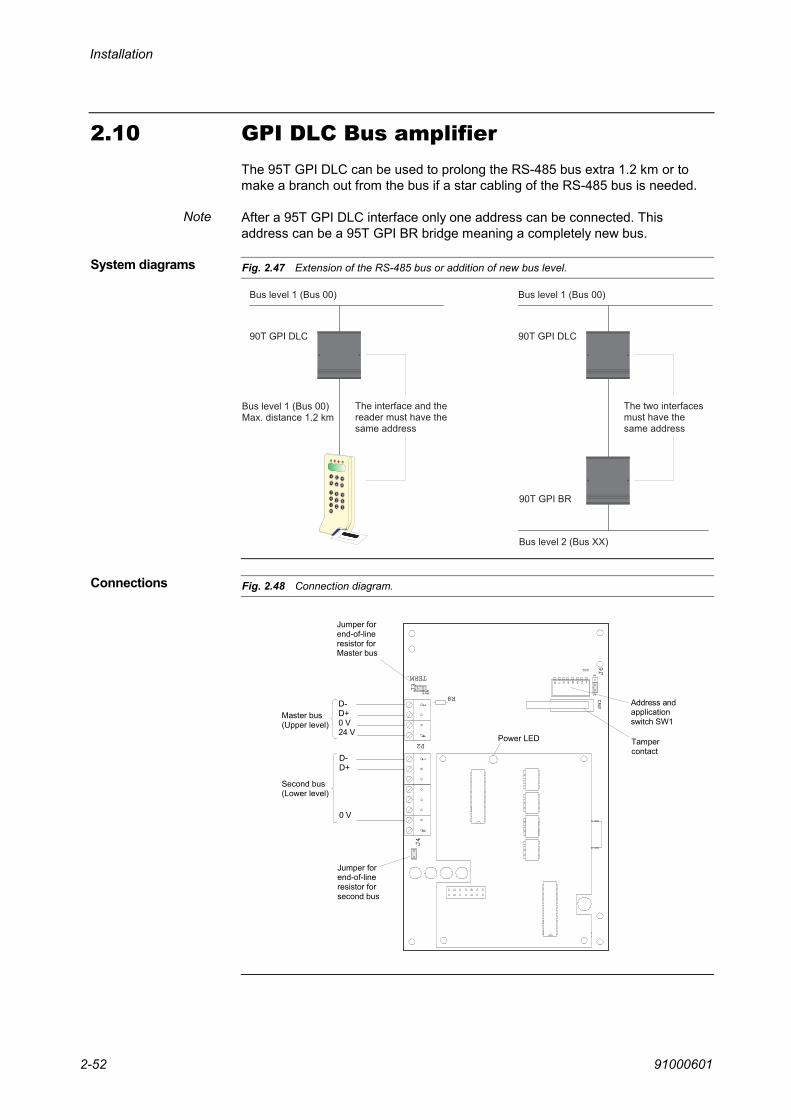
Installation
910006012-52
2.10 GPI DLC Bus amplifierThe 95T GPI DLC can be used to prolong the RS-485 bus extra 1.2 km or tomake a branch out from the bus if a star cabling of the RS-485 bus is needed.
After a 95T GPI DLC interface only one address can be connected. Thisaddress can be a 95T GPI BR bridge meaning a completely new bus.
Fig. 2.47 Extension of the RS-485 bus or addition of new bus level.
& "
& "
3 . * 8 * ? 3 . @
3 . * 8 * ? 3 . = = @
1 $ 0 ) # $ ' 4 ( ! . 3 . $ 1 ( 8 $ 1 . ( ( / / ' . .
& "
3 . * 8 * ? 3 . @
1 # $ ' 4 ( ! ( # / $ 1 ' ( / ' 3 . $ 1 ( 8 $ 1 . ( ( / / ' . .
3 . * 8 * ? 3 . @ ( 7 % / . $ ( # ! % +
Fig. 2.48 Connection diagram.
Master bus(Upper level)
Second bus(Lower level)
Tampercontact
Jumper forend-of-line resistor forMaster bus
P2
P1R8
14
18
SW1
SW2
J2
J5
J6
J3
J4
TERM.
Address andapplication switch SW1
13
12345678
Jumper forend-of-line resistor forsecond bus
D- D+0 V24 V
D- D+
0 V
Power LED
Note
System diagrams
Connections

Installation
91000601 2-53
2.11 RS-485 bus connectionsThe RS-485 bus is used for communication with Remote Keypads, Access ControlTerminals, remote printer interface etc. The RS-485 bus terminals in the Centralunit are placed on the 95T CUB 30 CPU board.
All units are connected in parallel on the bus as shown below . Star-connectionsexceeding 0.3 m in length are not allowed but the Central unit can be placedanywhere on the bus and does not need to be in one of the ends of the bus cable.
Fig. 2.49 Example of an RS-485 connection diagram.
6
The bus must be terminated in each end with a 220 Ω resistor. This end-of-lineresistor is present in all units, it must therefore be disconnected by removal of ajumper from the devices connected to the bus between the two ends of the bus. Inthe example above, the end-of-line resistor is still connected in the Access ControlTerminal and in the 95T CUB 30 CPU board which are both placed in the ends ofthe RS-485 bus. The jumpers are placed as shown in the figure above.
It is allowed to connect up to four bus devices to the power terminals (0V and24V) of the RS-485 bus of the CPU-board. Additional bus devices must bepowered from an external eparate power supply.
Please remember that the 0V must be connected through all devices includingthe external power supply.
In each Access Control terminal, you may connect a local separate S-ART buswith maximum 15 S-ARTs. This bus must not be connected together with theS-ART busses coming from the intrusion central unit. The S-ART bus of theAccess Control Terminal is used for connection of the door contact, electricstriking plate, exit pushbutton etc. to the reader. Please refer to the TechnicalManual of the Thor Access Control System for further information.
S-ART bus
Remote Keypad 95T RKP Remote Keypad 95T RKP
Remote keypad95T RKP
Access Control Terminal 95T ACM
JumperOFF
95T CUB 30 CPU board
Jumper OFF
Jumper OFF
JumperON
Jumper ON
Star-connected
Max.cable
length0.3 m

Installation
910006012-54
2.12 Cable length and dimensionWhen installing acoustical and optical warning devices, remote keypads andS-ARTs, cable length and current consumption must be taken into accountwhen selecting the cable dimension.
Connections to the I/O Board are carried out using standard installation cable.
For the RS-485 bus, shielded cable with twisted pair is recommended. The totallength should not exceed 1200 m, and the supply voltage at the end of the lineshould not drop below 10 V. All devices on this line must be connected in series- "star-connections" exceeding 0.3 m in length are not allowed.
For the S-ART lines, unshielded cable with twisted pair is recommended. Thetotal length including "star-connections" should not exceed 1000 m. The linevoltage at the far end should not drop below 12 V (normally 17 V). The minimumsupply voltage accepted depends on detector types etc.
The voltage drop of a two-wire cable (both conductors included) may becalculated from:
Ua = (Rd x Idc x L) : 500, where Ua = Voltage drop in volt.
Rd = Wire resistance in Ω/m.
Idc= Current consumption in mA.
L = Cable length in metres.
Resistance of a 0.6 mm diameter (0.25 mm²) cable is Rd = 6.15 Ω/100m.
Resistance of a 1.0 mm diameter (0.75 mm²) cable is Rd = 2.32 Ω/100m.
Resistance of a 1.4 mm diameter (1.50 mm²) cable is Rd = 1.16 Ω/100m.
Resistance of a 1.8 mm diameter (2.50 mm²) cable is Rd = 0.69 Ω/100m.

Installation
91000601 2-55
2.13 Current consumptionThe table below lists typical current consumptions at 12 V and 24 V for thevarious units of an intrusion system. All values provided are for one S-ART, onekeypad, etc.The values for the different S-ARTs do not include load on the outputs.
Equipment Normal Alarm
95T CU-30 Main controller 115 mA at 12 V 115 mA at 12 V
95T I/O - I/O Board 20 mA at 12 V 20 mA at 12 V
Remote Keypad/Card reader, 95T types.With backlight on, add 60 mA
60 mA at 24 V 60 mA at 24 V
90T GPI COM General Purpose Interface 50 mA at 24 V 100mA at 24 V(communicating)
99T IPI 110 mA at 12 V60 mA at 24 V
110 mA at 12 V60 mA at 24 V
95T GPI XXX IP 170 mA at 12 V120 mA at 24 V
170 mA at 12 V120 mA at 24 V
90T - S100 0 mA at 12V/24 V2 mA at 17 V
0 mA at 12V/24 V2 mA at 17 V
90T - S101 0 mA at 12V/24 V2 mA at 17 V
0 mA at 12V/24 V2 mA at 17 V
90T - S102 0 mA at 12V/24 V2 mA at 17 V
0 mA at 12V/24 V2 mA at 17 V
90T - S103 0 mA at 12V/24 V2 mA at 17 V
0 mA at 12V/24 V2 mA at 17 V
90T - S106 0 mA at 12V/24 V12 mA at 17 V
0 mA at 12V/24 V12 mA at 17 V
90T - S107 0 mA at 12V/24 V2 mA at 17 V
0 mA at 12V/24 V2 mA at 17 V
90T – S108 0 mA at 12V/24 V2 mA at 17 V
0 mA at 12V/24 V2 mA at 17 V
90T – S130 25 mA at 12V/24 V8 mA at 17 V
25 mA at 12V/24 V8 mA at 17 V
The listed values are useful for not only calculating cable length and dimension,but also for calculating the total power consumption and the battery capacityneeded. During log-on to a remote keypad etc., the current will increase withtypically 60 mA due to the backlight and status lamps.
For the calculation of the battery capacity needed, the S-ART consumption isthe total of the consumption at 24 V/12 V and at 17 V.


91000601 3-1
ProgrammingProgrammingProgrammingProgrammingThis chapter provides the information needed to program the intrusion systemfrom a remote keypad.
The chapter contains the following sections:
Section Page
General 3-2
Start-up procedures 3-3
Programming of input addresses 3-5
Programming of output addresses 3-6
Programming of zones, areas and codes 3-7
Programming of remote keypads to zones 3-8
Auto set time programming 3-9
Introduction
This chapter

Programming
910006013-2
3.1 GeneralAll programming of the system can be performed from any of the Remotekeypads.
When a system is going to be installed it is only pre-programmed with theinternal monitoring addresses, and all external addresses, zones etc. must bedefined in the user programming.All programming menus are explained in Chapter 4, Operating instructions.
To start-up, a Card reader please refer to the Technical Manual for Thor AccessControl System.

Programming
91000601 3-3
3.2 Start-up procedures
3.2.1 Start-up of a Thor Intrusion central unit.To start-up a Thor central unit the following must be connected as a minimum:
A Remote keypad or card reader on the RS-485 (the card reader must beinitialized to mode 03)
The BAT ON/OFF Jumper must be connected on the CPU-board.
After connecting the power and short-circuiting the reset pins (approx. 2 s)placed on the CPU-board, the following procedure can be followed to program anew system. Please note the switch setting (SW1) on the CPU-board for thedifferent software modes.
Step What to do …
1 Enter the preliminary Service Code 654321. If a reader is used to initialize a Thorintrusion system a special procedure is used to call the preliminary engineer codeas follows:
a: Press - key and read the Master card.b: Press - key (YES) for Intrusion Menus.c: Key in 01.d: Key in the preliminary engineer code 654321.
2 Call Menu 50 to put the system in Service Mode and then Menu 42 to programthe normal engineer code and alarm patrol code.
3 Call Menu 45 to allocate an area No. and a priority 4 to the engineer code and apriority 3 to the alarm patrol code. If a card reader is used as a terminal theservice user No. must be No. 101, as this user No. is predefined to the servicecard for the reader. After this, it is possible to make a new log-on with the normalengineer code.
4 Call Menu 43 to program all zone names.
5 Call Menu 44 to define the zone - area relationship. The areas 1 to 8 must beused for auto set. If this feature is not used, they can be programmed freely.
6 Call Menu 45 to allocate users to the defined areas and the user priority. One ormore users can be defined for each area. In this menu only a user number isdefined, the code is programmed in Menu 42. The service engineer can programnormal operator codes during start-up only, meaning that an engineer codecannot change any already programmed codes
7 Call Menu 46 if the predefined detector name list must be changed.
8 Call Menu 47 to set-up all input addresses in the installation. To each address isprogrammed a zone no., an input soft type no., a detector name no., and fourattributes.
9 Call Menu 48 to setup all output addresses in the installation and the belongingzone No. or total installation.
10 Call Menu 49 to set-up the timers in the system. Each timer can be connected toone or more output soft types, which is done in Menu 53.
Continued …

Programming
910006013-4
Step What to do …
11 Call Menu 53 to connect the defined timers to the wanted output soft types.
12 Call Menu 57 to program the Alarm Functions.
13 Call Menu 54, if some of the Remote keypads or Card readers must be allocatedto special zones. All panels are preprogrammed to cover all zones.
14 Call Menu 52 to program the Site code (if any) and the RS-485 communicationmode (option 8). If the RS-485 communication mode is changed, the central unitmust be reset before the new communication mode starts.
15 Normally the built-in clock does not need to be adjusted as it runs on the internalRAM-memory back-up battery. Even if the BAT ON/OFF switch on theCPU-board has been in the off position, it is not necessary to program the timeand date in Thor. If, anyhow adjustment is needed it is done by calling Menu 41.
16 Call Menu 42. All user codes can be programmed. Please note that the Servicecode cannot change already made user codes but only create these the firsttime.
17 Call Menu 51 to leave Service Mode. Also if the system has been reset the menu51 must be called to leave Service Mode.
18 Call Menu 55 to program the area week programs and the connected function toeach time period. When a week program is made for one area, exit the Menu 55,and the same menu must be called again, if another area should beprogrammed.Up to eight areas can be programmed with each a different week program.
19 Call Menu 56 to program the holiday list connected to the two special daysprogrammed in the above menu.
20 Call Menu 28 to make a print-out of the complete system programming.
The Auto Set is then ready for use and will perform the programmed function atthe first coming programmed time.
In the sections 3.3 to 3.7 are explained in details the programming philosophyfor the mentioned programming menus in the start-up procedure.

Programming
91000601 3-5
3.3 Programming of input addressesAn input address in Thor can be an S-ART, a loop on the I/O-board or an internalmonitoring function, for example, monitoring of the RAM memory. All used inputaddresses must independent of these hardware types of signals be programmedwith the parameters shown in the below figure. The internal monitoring addressesare preprogrammed with some predefined data (See Chapter 1, Functionaldescription). However, these data can be changed if required.
Fig. 3.1 Input address parameters.
As shown an input address is defined by:
A soft type defining the function of the address (Menu 47).
A physical zone where the address (detector) is installed (Menu 47).
A detector name that will be displayed in case of alarm or fault messagesfrom the address. A list of max. 250 names can be made by the Menu 46and the connection to the address is programmed with Menu 47.
Four attributes connected to each address. The function of the attributes isdescribed in Section 1.5.2.
The Menus 46 and 47 are explained in details in Chapter 4, Operating Instructions.

Programming
910006013-6
3.4 Programming of output addressesAn output address in Thor intrusion can be an S-ART or an output on the I/Ointerface board. An S-ART can be used as an input address and as an outputaddress at the same time and with complete independent functions. All usedoutput addresses must be programmed with the parameters described and shownin the figure below.
Fig. 3.2 Output address parameters.
In Menu 48, each output address must be programmed with an output soft type.A zone No. is programmed in the same menu. This zone No. defines whichinput in which zone activates the output address. It is not necessarily thephysical zone where the output is placed. For example, it is possible to have azone for a vault with some detectors and then an output programmed with anoutput soft type with the same zone No. in the guard room to activate videoequipment in case of alarm from the vault zone.
If the zone No. is programmed as 00 the output will react as a general signalfrom the complete system for this output soft type.
As shown in the above figure, to each output soft type by zone a timer can beconnected. This means that for example all output addresses defined as outputsoft type No. 1 (Common alarm 1) in zone 01 uses timer No. 7, which has beenprogrammed to have a duration of 180 s, no delay and a timer type 1 (normallyoff). Other addresses with output soft type No. 01 but defined for another zonethan 01, can be defined to another timer No. The timer definition regardingoutput soft type and zone No. is made in Menu 53.
Before connecting timer No. to output soft type no., each timer No. must bedefined with a timer type. Seven different timer types are available, see thefigure and the function description for exact definition of each timer type. In thetimer type programming it is decided, if the output soft type will be normally on /off, pulsating etc.

Programming
91000601 3-7
3.5 Programming of zones, areas and codesIn the figure below is shown the relation between zones, areas, users and codes.
Fig. 3.3 Relation between zones, areas, users and codes.
Each user can have a six digit pin-code, see code list and a priority P0 to P6(see User list), which defines the menus the user is allowed to use.
Several users can be connected to one area. All set / unset manipulations withthese user codes will physically set or unset the area, meaning that the firstcode belonging to the area will set or unset the area not depending on what hasbeen done with the other codes to the area.
Two types of areas can be defined, logical or physical, describing the set/unsetprocedures.
Physical areas: If the areas 001 and 002 in the above shown example are definedas physical areas the setting and unsetting of the common zone 01 will work asfollows: The first code from area 001 or 002 in the morning will unset thecorresponding area and also the common zone. In the evening when the first areais set, the common zone 01 will also be set. If the people from the other area mustleave the building through the common zone, this programming does not work andthe areas must be defined as logical areas as explained below.
Physical areas are indicated by "axxx" in the System Programming print-out.
Logical areas: If the areas 1 and 2 are defined as logical areas the setting andunsetting of the common zone 01 will work as follows: The first code from area001 or 002 in the morning will unset the corresponding area and also thecommon zone. In the evening when the first area is set the common zone 01 willnot be set before all areas covering the common zone have been set. In thiscase the people from area 001 can set the area and leave the building and thepeople in area 002 can still work and leave through zone 01 and make thesetting of area 002, when they want. The setting of zone 01 takes place whenboth areas are set.
Logical areas are indicated by "Axxx" in the System Programming print-out.

Programming
910006013-8
3.6 Programming of remote keypads to zonesIn Menu 54, a Remote keypad or other type of operating terminal can beprogrammed to belong to one or more zones. This feature is illustrated by theexample below.
Fig. 3.4 Division of an area into zones.
The remote keypad near the entrance door is programmed to cover zone 01, 02,03 and 05 and the RKP near the stock to cover zone 04. A user code for area 1covering zone 01 to 05 will set and unset - at the main entrance RKP - zone 01,02, 03 and 05 but not 04.The same user code used on the RKP 2 will only set and unset zone 04. By doinglike described, it is possible with the same code to set/unset different zones fromdifferent RKPs and it is not necessary for the user to remember more than onecode.

Programming
91000601 3-9
3.7 Auto set time programmingThis section describes the week time programming for auto setting including theautoset and autounset functions and the holiday list.
3.7.1 Area week time programmingThe week time programs for auto setting can be programmed by a P2 or P4user code. It is possible to auto set and unset up to max 8 areas, area 001 to008. For each area, a separate week program must be programmed.
A week program comprises 7 days: Monday to Sunday plus 2 special dayswhich refer to the holiday list. In this way, it is also possible to program halfworking days, for example the 24th of December or other specific dates.
The figure below shows an example of a typical time program for a normal day.
Fig. 3.5 Example of typical time program for a normal day.
One day can have max. 8 periods where the first always starts at 00:00 and thelast always at 24:00. In the above example, the system is set until 8:00, afterwhich it is possible to unset the area. However, the area is not unset before 9:00by the first coming user. At 12:00, it is automatically set and again unset at14:00. At 18:00 it is auto set if no user has requested a delay in the setting. If auser has requested a delay, the auto set will take place at 20:00 and thecomplete program changes to the next day at 24:00.
Each period must be programmed with a function (FNC). Eleven functions FNC1 to FNC 11) are available as described below.
Setting the area at the beginning of the period or setting at the end of the periodif delay has been requested from one of the Remote keypads. Delay can only berequested once
Setting the area at the beginning of the period.
Setting the area at the beginning of the period and enabling manual unsetting atthe end of the period.
Unsetting the area at beginning of the period.
No change.
FNC 1
FNC 2
FNC 3
FNC 4
FNC 5

Programming
910006013-10
At the beginning of the period and each 10 minutes in the period, it is verified thatthe area is set. If the area is not set, an alarm is generated on an input addresscorresponding to the area number. There is no reaction if the area is set.It is possible to delay the function in the pre-warning period. If this is the case, theverification will only take place at the end of the period.
Related inputs:
Area 1: Input No. 62 Area 4: Input No. 65 Area 7: Input No. 68
Area 2: Input No. 63 Area 5: Input No. 66 Area 8: Input No. 69
Area 3: Input No. 64 Area 6: Input No. 67
FNC 6 corresponds to FNC 5 (No change) in the way that it is the prior functionthat decides the use of code priorities. If for example, the function before FNC 6is a FNC 2, then it is not possible for P0 and P1 codes to perform an unsetting.Only if another function used before FNC 6 allows the unsetting, a manualunsetting can be performed.
When the function becomes active and the area is unset, then a timer is started(timer 18 –duration in minutes) and when the timer expires, the area isautomatically set. 10 minutes before the automatic setting the pre-warningoutput type is activated, as normal.If the area is unset when the function is active, the timer will be started asabove.It is possible to delay the automatic setting (when the pre-warning is active) bymeans of Menu 14. The setting is then delayed for the programmed time (Timer18 – delay in minutes).
Operates as FNC 1. However, if there are any active detectors in the area to beset, the setting is cancelled and a set fault message is sent.This message will contain a list of all the detectors that where active when theAuto-Arm function would have set the area, maximum 100. The message issent to following devices: Alarm / event transmitter, INCOM, GPI Host interfaceand Modem interface.
Operates as FNC 2. However, if there are any active detectors in the area to beset, the setting is cancelled and a set fault message is sent.This message will contain a list of all the detectors that where active when theAuto-Arm function would have set the area, maximum 100. The message issent to following devices: Alarm / event transmitter, INCOM, GPI Host interfaceand Modem interface.
Allows manual unsetting at the start of the period. If the area is not unset at theend of the period, the area+1 is set automatically.
Allows manual setting and unsetting at the start of the period, but only when thearea is unset when the period starts.
FNC 6
Note
FNC 7
FNC 8
FNC 9
FNC 10
FNC 11

Programming
91000601 3-11
3.7.2 Holiday listA holiday list of 25 periods can be made in Menu 56. For each period, a day No.(1-9) must be programmed, which refers to the 7 week days and 2 special daysin the area week program.
Normally 2 different special days will be programmed. One day, which is closedthe whole day and another day, which is open half day. This makes it possible tohave special opening times for certain dates during a year.
It is also possible to use one of the normal week day No. 1 - 7 together with aperiod in the holiday list, if the programmed time for this day is suitable for theholiday period.
The holiday list is common for all 8 area week programs using the same day ref.No. from each week program.
Please refer to Section 4.6 for the Menu 56 for information about programming.

Programming
910006013-12
This page is intentionally left blank.

91000601 4-1
Operating instructionsOperating instructionsOperating instructionsOperating instructionsThis chapter describes the operating facilities of the remote keypads and theway in which the system is operated on a daily basis. In addition to this, anoverview of the available menus gives an introduction to the following sectionsdescribing in detail the function keys of the keypads, and the operator codes andpriority. After this follows a detailed description of the individual menus and theiruse.
The chapter contains the following sections:
Section Page
Operating facilities 4-2
Operation in general 4-3
Submenu 2 - Display/change of status 4-17
Submenu 3 - System test 4-22
Submenu 4 - Programming 4-26
Autoset programming 4-40
Introduction
This chapter

Operating instructions
910006014-2
4.1 Operating facilitiesThe user terminal (Remote Keypad) has four Indication lamps, a two-linealphanumeric display and a numeric keyboard with six additional function keys.The four indication lamps are used for the following functions:
Green power lamp:Indicates mains power present. Flash indicates battery operation (mainspower dropout).
Red alarm lamp:Lit after log-on to indicate the presence of an alarm condition within thekeypad-area. The alarm condition can be seen on the display. Turnedoff, when all alarm messages are reset.
Yellow system fault lamp:Lit after log-on to indicate the presence of a system fault within thekeypad-area. The fault condition can be seen on the display. Turned off,when all fault messages are reset.
Yellow set lamp:Lit after log-on, when all zones of the code used are set (code-area set).
DisplayTwo lines of each 16 characters displaying the status of the system and operatinginstructions. Normally date and time are displayed. The backlight is turned-on assoon as the keyboard is activated and automatically turned-off again two minutes(normally) after the last keystroke.
BuzzerUsed for acoustical indication of alarm/fault and entry/exit time. Also activated for ashort time to indicate operating fault.
KeyboardThe keyboard includes the numerical keys to used for entry of codes etc.and six function keys:
This key is used for setting.
This key is used for unsetting.
This key is used for alarm/fault reset.
This key selects the displayed menu-function.
This key is used for step back and log-out.
This key steps through the different menus.
The function keys are described in detail in Section 4.2.5.

Operating instructions
91000601 4-3
4.2 Operation in generalThe Thor operating procedure is menu-based which means, that all operatingfeatures are displayed as the operator replies to the questions asked bypressing YES ( - key) or NO ( - key).
The menu includes a main menu for daily operating and three sub-menus forstatus display or change of status, system test and programming. Operatingrequires a 6-digit code to be keyed-in. The menu-functions displayed depend onthe code-priority (Seven levels).
4.2.1 Daily operationPrior to any operating procedure, date and time are displayed. This is also thenormal display upon log-out (by means of the - key or automatically afternormally 2 minutes without operating). In case the system holds alarm/faultmessages, which the operator in question might have the priority to reset, but hasnot yet done so, the buzzer sounds for approx. 15 s at log-out.
Fig. 4.1 Example of Normal display.
The backlight of the display is normally turned-off, but is turned-on as soon as thekeyboard is used - and an access code is requested. A flashing cursor indicateswhich digit is expected. If the first keystroke was a decimal figure, it is regardedfirst digit of the code. Digits are indicated by * in the display. By entering an illegalcode, the buzzer sounds for a short while and a new attempt is requested. Afterthree attempts, the keypad is blocked for 5 minutes.
Fig. 4.2 Example of Access code request.
After code acceptance, status of the code-area (or zone) Menu 10 is displayed.
Menu 00
Menu 01

Operating instructions
910006014-4
Fig. 4.3 Example of Display of status of code-area.
The set/unset condition displayed depends on whether your code is allocated toa physical area or to a logical area.Codes allocated to a logical areas operates in such a way, that zones commonto more of those areas are not physically set until all such areas have beenrequested set.Codes allocated to a physical areas perform normal physical setting/unsetting ofthe common zones.You can read Section 1.4, The logical area concept, to get more informationabout logical and physical areas. See especially page 1-13.
By using the - key, the set/unset condition of zones belonging to the area aredisplayed one by one, and may be altered physically by means of the or keys. In case of alarm messages etc. within the zone in question, the number ofalarms is displayed. After having displayed the last zone, or at any time usingthe - key, the area condition is displayed again.
AREA UNSET means, that all detectors (apart from tamper etc.) of the area are unset.
PARTIALLY SET means, that only a part of the area is set, either because thesetting was performed by means of a keypad belonging to only a part of thearea, or because zones or detectors have been individually set/unset in Menus10, 22 or 23.
AREA SET means that all detectors of the area are set (no isolations). Zonescommon to more logical areas are not physically set until the last one of suchareas have been set.
SYSTEM SET means, that all areas are set (isolations may be present).
ZONE NAME UNSET means, that all detectors (apart from tamper etc.) of thezone are unset.
ZONE NAME P.SET means, that some detectors (apart from tamper etc.) of thezone are physically set and some are either unset.
ZONE NAME SET means that all detectors of the zone are set (isolationsaccepted).
Normally the lower line displays operating instructions SET= or UNSET= .
In case of alarm messages etc., the lower line of the display informs of thenumber of alarm messages (if present) or system fault messages (if present) orisolated detectors. By means of the - key a jump to the Alarm List Menu 11 orthe System Fault List Menu 12 or the Isolated Detector List Menu 13 occurs.
If no operating steps are performed within 5 s, alarm and system fault messagesare displayed automatically one by one in intervals of 2 s. See Autoscroll, page 4-9for more information.
Menu 10:
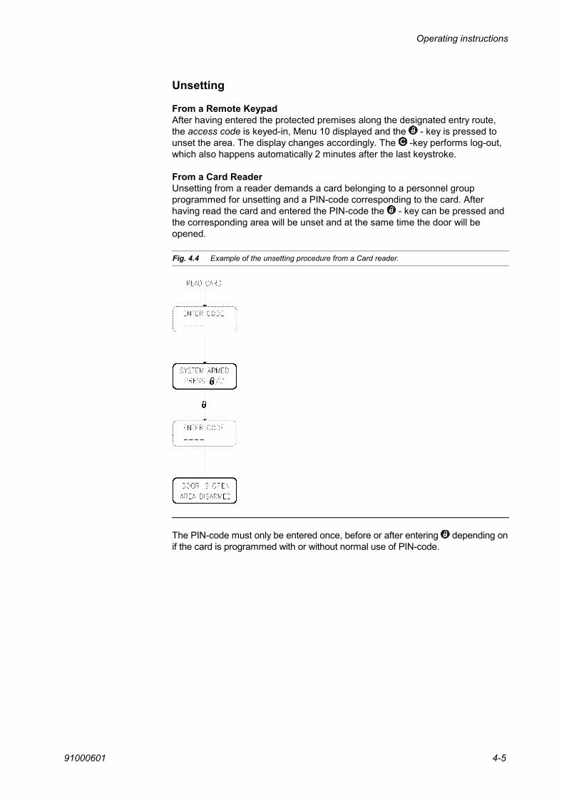
Operating instructions
91000601 4-5
Unsetting
From a Remote KeypadAfter having entered the protected premises along the designated entry route,the access code is keyed-in, Menu 10 displayed and the - key is pressed tounset the area. The display changes accordingly. The -key performs log-out,which also happens automatically 2 minutes after the last keystroke.
From a Card ReaderUnsetting from a reader demands a card belonging to a personnel groupprogrammed for unsetting and a PIN-code corresponding to the card. Afterhaving read the card and entered the PIN-code the - key can be pressed andthe corresponding area will be unset and at the same time the door will beopened.
Fig. 4.4 Example of the unsetting procedure from a Card reader.
The PIN-code must only be entered once, before or after entering depending onif the card is programmed with or without normal use of PIN-code.

Operating instructions
910006014-6
Setting
From a Remote KeypadThe access code is keyed-in, Menu 10 displayed and the - key is pressed toinitiate the setting procedure.
Fig. 4.5 Example of setting the system from a remote keypad (RKP).
Normally you are then requested to leave the premises along the designatedentry/exit route - the buzzer sounds to indicate exit time is running. The - keyperforms log-out, which also happens automatically 2 minutes after the lastkeystroke.
In case setting is not possible due to the condition of the system, the individualreasons - active detectors - are displayed (non-reset passive alarm and systemfault messages do not affect the setting procedure). If a detector fault cannot becorrected (window closed etc.), the detector may be isolated (depends ondetector type and code priority) using the - key, upon which the next fault isdisplayed. No more than one detector within each zone is allowed isolated usingcode priority P0-P1. At an attempt of isolating more detectors, Menu 10 isdisplayed as AREA UNSET - 001 ISOLATIONS. P2-P4 codes are allowed toisolate an unlimited number of detectors.
By using the - key, elements of the detector fault list are just displayed (notisolated) - after the last element, Menu 10 appears again allowing for a newattempt of setting.
Such isolated detectors take no part in the setting procedure to follow. Upon thenext unsetting, the condition of these detectors are normal unset again.
Please note that detectors in the exit/entry route (input soft type 4) will not give aSet fault indication in case of active detectors, but if the detector is still active atthe end of the exit time give an external alarm.
In case the alarm input of a detector is active, it may be isolated withoutdisabling the ability to react to a tamper alarm condition.
If the central unit is setup to work in the Bank mode (see CPU switch setting),another possibility exists when the setting of an area is giving a set fault. Instead of isolating the detector a "forced setting" can be performed. This is doneby using the - key twice when having a set fault from a detector. The systemwill then perform the setting and go into alarm condition.

Operating instructions
91000601 4-7
Fig. 4.6 Example of normal setting and forced setting.
From a Card Reader:Setting of an area from a reader demands a card belonging to a personnel groupprogrammed for setting and a PIN-code corresponding to the card. After havingread the card and entered the PIN-code the - key can be pressed and thecorresponding area will be set.
Fig. 4.7 Example of setting the system from a Card reader.
The PIN-code must only be entered once, before or after entering , depending on ifthe card is programmed with or without normal use of PIN-code.
In case setting is not possible because of active detectors, the reader willdisplay the same menus as in the Remote Keypad and the procedures to isolateetc. are the same as described above.

Operating instructions
910006014-8
Fig. 4.8 Example of displaying alarms.
By NO ( ), Menu 12 appears.
All alarm messages of the system or within the code-area (depends on systemprogramming) are displayed including DETECTOR NAME, alarm type(HOLD-UP, TAMPER, ALARM, FIRE or TECHNIC), actual input condition (+ forACTIVE and - for QUIET) and ALARM TIME in order of appearance - except forthe first alarms, which are always hold-up alarms, if present. If the event belongsto the area of the code, it is erased from the list by pressing the - key, uponwhich the next event is displayed. If the element is not erased the buzzer soundsfor a short time and the display remains unchanged. In this case the - key isused to display the next element. By means of the - key additional informationconcerning zone relationship, detector number and actual input condition aredisplayed. This key is also used to return to the list again.
After having tried to reset all events, the list holds the elements only, which cannotbe reset - either because the operator is not allowed to or because the actualcondition of the input (see input types) does not allow for resetting. Such remainingmessages are displayed by pressing the - key repeatedly. When the list isempty, Menu 11 appears again; this is also achieved using the - key.
Fig. 4.9 Example of displaying system faults.
By NO ( ), Menu 13 appears.
All fault messages of the system or within the code-area (depends on systemprogramming) are displayed including DETECTOR NAME, actual input condition(+ for ACTIVE and - for QUIET) and FAULT TIME in order of appearance. If theevent belongs to the area of the code, is erased from the list by pressing the
- key, upon which the next event is displayed. If the element is not erased thebuzzer sounds for a short time and the display remains unchanged. In this casethe - key is used to display the next element. By means of the - keyadditional information concerning zone relationship, detector number and actualinput condition are displayed. This key is also used to return to the list again.
After having tried to reset all events, the list holds the elements only, which cannotbe reset - either because the operator is not allowed to or because the actualcondition of the input (see input types) does not allow for resetting. Such remainingmessages are displayed by pressing the - key repeatedly. When the list isempty, Menu 12 appears again; this is also achieved using the - key.
If a log-out is performed with alarm or system fault messages not erased, theRemote Keypad will sound the buzzer in 15 seconds to remind the user not toforget to clear information, which is not valid any more.
Menu 11:Alarm display
Menu 12:System fault display

Operating instructions
91000601 4-9
Fig. 4.10 Example of displaying list of isolations.
By NO ( ), Menu 10 appears.
All detectors of the system or within the code-area, isolated during the settingprocedure or in Menu 23, are displayed including DETECTOR NAME, ZONENAME, DETECTOR NUMBER and actual input condition (ACTIVE or QUIET) byusing the - key and the - key. When the - key is pressed, Menu 13appears again.
Fig. 4.11 Example of automatic presentation of system messages by means of autoscroll.
The - key will unset the area, but not stop the autoscroll. The - key will setthe area and stop the autoscroll. The - key will reset the alarm or faultmessage (if so allowed), but will not stop the autoscroll. The - key and the
- key will perform immediate operation as usual, but not stop the autoscroll.The - key will stop the autoscroll and perform a step back as usual.
The purpose of autoscroll is to present messages of the system to untrainedpersonnel in an automatic way. After log-on, the main menu (set/unset conditionof the area) remains for 5 s. In case of alarm messages or system faultmessages, each element is displayed for 2 s. After the last message, the mainmenu is displayed again, and the sequence is repeated.
Menu 13:List of isolations
Autoscroll

Operating instructions
910006014-10
Fig. 4.12 Example of delaying autoset.
By NO ( ), Menu 10 appears.
In systems where auto-set time programs are programmed it is possible to delaythe auto-set each period in the week program by calling Menu 14. After keying inthe area number (between 1 - 8), the auto-set time will be delayed the specifiedtime. By pressing , the menu is left without delaying the auto-set time.
Menu 14 can be called from all types of Remote Keypads or Card readers.
4.2.2 Sub-menusFrom the daily operating procedure a jump to the special functions is performedby entering XX, where XX indicates the number of the wanted function.
The special functions are divided into three submenus:
Fig. 4.13 The three submenus with special functions.
Direct jump to any menu can be made by entering the menu number indicated onthe menu overview diagram.
Menu 14:Delay autoset

Operating instructions
91000601 4-11
4.2.3 Intrusion menus on the Card ReaderThe above description is valid for using the system from a Remote Keypad. To dothe same on a Card Reader the following procedure can be used.
Fig. 4.14 How to access the three submenus with special functions from a Card Reader.
When using the card reader to operate the intrusion system it is necessary with acard and a corresponding PIN-code. Before reading the card the - key ispressed to tell the reader not to open the door but to go into "Menu" - mode. Afterentering the card and PIN-code, the user has the choice between "Access Menus"or "Intrusion Menus". Choosing the "Intrusion Menus" the user can do all themenus described in this manual.

Operating instructions
910006014-12
4.2.4 Overview of the menusThe overview of the menus in the figure below shows how reach the menus andthe priority required to get access to the displays of the menus for viewing,testing and programming.
Fig. 4.15 Overview of the menus available with number and priority required for access to the displays of the menus.

Operating instructions
91000601 4-13
4.2.5 Use of the function keysIt is always possible to use function keys different from the ones suggested bythe display.
If the unsetting key is pressed, when a menu-picture is displayed (not inside aselected menu), all zones of the operating keypad common to the code used areunset, after which the new condition is displayed by Menu 10. During isolation ofsetting faults and inside Menu 22 (zone setting-unsetting) and Menu 23 (detectorsetting-unsetting-isolating) the key unsets a part of the system only.
If the setting key is pressed, when a menu-picture is displayed (not inside aselected menu), all zones of the operating keypad common to the code used areset, after which the new condition is displayed by Menu 10. In case of settingfaults however, a fault list appears. Inside the Menus 21 (area setting), 22 (zonesetting-unsetting) and 23 (detector setting-unsetting-isolating) the key sets a partof the system only.
If the reset key is pressed after having entered Menu 50 (service mode), anattempt is made to reset all the alarm/fault messages, the code used is allowedto reset, after which the new condition is displayed by Menu 10. Please note thatit takes app. 3 s by alarm or fault message before returning to Menu 10. Duringalarm reset (Menu 10 and 11) and fault reset (Menu 10 and 12), attempts aremade to reset messages one by one only.
In the System Programming Menus the cursor can be moved to the right bythe - key to the wanted place where a new parameter is needed.
When the menu key (NO-key) is pressed, the next menu appears. By pressingthe - key in a sub-menu, the display will show the starting point of thissub-menu. During display of most lists etc., the key is used to bring the nextelement forward. After having displayed the last element, you are returned to thefirst element.
The select key (YES-key) is used to select the displayed Menu. It is also used toget more information, when an input (detector) condition is displayed - and toreturn to the first picture. Such additional information is not necessarily neededby the operator, but is useful to engineers as zone name, detector number, typeof event and actual input condition are included.
Fig. 4.16 Explanation of the detector window content.
This key performs an escape/log-out function. When it is pressed inside a selectedmenu, a jump back to the menu select picture occurs. By pressing the - key, thestarting point of the sub-menu will appear and finally back to Menu 10.A maximum of four activations are required to log-out and turn-off the backlight ofthe display. This also happens automatically 2 minutes (normally) after the lastkeystroke.
Detector window

Operating instructions
910006014-14
4.2.6 Operator codesIn order to make a change of status such as setting, alarm reset, system test,programming etc. a 6-digit code must be entered. This code is allowed tooperate the complete system or a part only as defined by programming.
To each code belongs a hold-up code equal to the code + 1. Codes with lastdigit = 9 have no hold-up function. When a hold-up code is used, a time-limitedtransmission to the alarm station takes place. The condition is not indicated inthe display, just by the event-log and some output types.
Special hold-up codes can also be created. These codes will give the above-described reaction and they are programmed by giving the user a priority P5.
Upon three unsuccessful attempts of entering a code, the keypad is blocked forfive minutes.
When a code is modified, it is compared to all other codes of the system andrejected in case of to big resemblance (4 similar digits). 000000 may always beprogrammed and disables the code. Upon CPU-reset certain predefined codesare available, see Menu 42.
250 codes with different priorities (up to seven – P0 to P6) can be programmed.See the following section for more information.
4.2.7 Code priorityThis section describes the priority that can be assigned to the individual users ofthe system. Seven priorities are available.The priority defines the operating rights assigned to the operators as follows:
The low priority operator code allows the user to set his own area. The P6 userhas only access to Menu 10 and the - key to display zone status. The P6 usercannot reset alarms, but entry of the code will stop sirens, bells, etc.
The hold-up code has the same rights as a P0 code. When using a P5 code, ahold-up alarm will be created as described above.
The engineer code allows for all kinds of operation - except from changing P0 -P2 codes. The code is accepted 2 minutes after an alarm/fault condition, andmay be used until all such messages are reset. A P1 - P2 operator may allow,by typing 50, the engineer code to be used one time only - until log-out.When a P4 code types 50, the system is in service mode allowing for unlimiteduse of the engineer code for general alarm/fault reset, most system test etc.until service mode is reset by typing 51 (all codes are allowed to do so).
The system programming (Menu 43 -54) requires service mode. Service modeis indicated by a pseudo-fault message being displayed and a transmissionoutput "Trouble" being activated (both automatically reset by typing 51) andprevents alarm conditions from activating the local strobe and bell outputs.
The alarm patrol code allows for most kinds of operating - except from systemprogramming and some system test facilities. The code is accepted 2 minutesafter an alarm/fault condition, and may be used until all such messages arereset.
Priority P6
Priority P5
Priority P4
Priority P3

Operating instructions
91000601 4-15
The master manager code allows for all kinds of operating - except fromchanging P3-P4 codes, input test and system programming. Can allocate Usersto Areas and change the priority for a user (P0 to P2 only) (Menu 45). Canalways override automatic set/unset commands. Can make a reset of tamperalarms if the Option bit 5 (Menu 52) enables this function.
The manager code like P2 allows for most kinds of operating, most testfacilities, changing of date and time and change of own code and P0 codes.Cannot in Bank mode unset an area, which includes zones controlled by anautomatic set period. Can only isolate one detector in each zone.
The operator code allows for setting/unsetting, alarm/fault reset (not tamperalarm and some system faults) and lamp test. Cannot unset an area, whichincludes zones controlled by an automatic set period. Can only isolate onedetector in each zone.
Function or menu No. Description P0 P1 P2 P3 P4 P5 P6
Unset: Own area Yes Yes Yes Yes Yes Yes No
Auto set area No No Yes No Yes No No
Foreign area No No No No No No No
Set Own area Yes Yes Yes Yes Yes Yes Yes
Foreign area Yes Yes Yes Yes Yes Yes No
Isolate detectors Yes* Yes* Yes Yes Yes Yes* Yes*
Reset Alarm (intrusion) Yes Yes Yes Yes Yes Yes No
Tamper alarm No No Yes/No Yes Yes No No
Hold-up alarm Yes Yes Yes Yes Yes Yes No
Technical alarm Yes Yes Yes Yes Yes Yes No
Fire alarm Yes Yes Yes Yes Yes Yes No
Battery/1h mains fault Yes Yes Yes Yes Yes Yes No
System faults No No No Yes Yes No No
Menu 14 Delay auto-arming Yes Yes Yes Yes Yes Yes No
Menu 21 Display area status Yes Yes Yes Yes Yes Yes No
Menu 22 Display zone status Yes Yes Yes Yes Yes Yes No
Menu 23 Display detector status Yes Yes Yes Yes Yes Yes No
Menu 25 Display event-log No Yes Yes Yes Yes No No
Menu 26 Print event-log No Yes Yes Yes Yes No No
Menu 27 Print status No Yes Yes Yes Yes No No
Menu 28 Print programming No No Yes No Yes No No
Menu 29 Display alarm counter No No Yes No Yes No No
Menu 31 Test lamps Yes Yes Yes Yes Yes Yes No
Menu 32 Test PIR etc No Yes Yes Yes Yes No No
Menu 33 Test battery No Yes Yes Yes Yes No No
Menu 34 Test zones No Yes Yes Yes Yes No No
Menu 35 Test inputs No No No No Yes No No
Menu 36 Test outputs No No Yes No Yes No No
Menu 37 Test printer No Yes Yes Yes Yes No No
Menu 38 Test bells No Yes Yes Yes Yes No No
Menu 41 Program date and time No Yes Yes Yes Yes No No
Menu 42 Program access codes No Yes Yes No Yes No No
Menu 43 Program zone names No No No No Yes No No
Menu 44 Program area-zones No No No No Yes No No
Menu 45 Program code-area No No Yes No Yes No No
Menu 46 Program detector names No No No No Yes No No
Menu 47 Program inputs No No No No Yes No No
Continued ...
Priority P2
Priority P1
Priority P0

Operating instructions
910006014-16
Function or menu No. Description P0 P1 P2 P3 P4 P5 P6
Menu 48 Program outputs No No No No Yes No No
Menu 49 Program timers No No No No Yes No No
Menu 50 Allow for service code No Yes Yes No No No No
Set in service mode No No No No Yes No No
Reset all alarm/fault No Yes Yes Yes Yes No No
Menu 51 Cancel service mode Yes Yes Yes Yes Yes Yes No
Menu 52 Program Options and Site code No No No No Yes No No
Menu 53 Program output-timer No No No No Yes No No
Menu 54 Program keypad-zones No No No No Yes No No
Menu 55 Program Auto Set programs No No Yes No Yes No No
Menu 56 Program Holiday list No No Yes No Yes No No
Menu 57 Program Alarm Functions No No No No Yes No No
Menu 58 Adjust clock (CU-30 only) No No Yes Yes Yes No No
Menu 59 Reset No No No No Yes No No
* Only 1 detector in each zone.

Operating instructions
91000601 4-17
4.3 Submenu 2 - Display/change of statusThis section describes the menus and displays of submenu 2 used for displayingand changing the status of areas, zones and detectors, viewing and printing theevent log and printing the system programming.
Fig. 4.17 Example of Menu 21: Area status with associated displays.
By NO ( ), Menu 22 appears.
The setting condition (UNSET, PART SET or SET) and alarm condition (QUIET,ACTIVE (active inputs), ALARM or FAULT (system fault)) of each area, included inthe keypad-area, are displayed. If the condition is normal (QUIET), a (partly) unsetarea may be logically set by means of the pushbutton - even though the areaincludes zones not belonging to the code used. Zones of the area belonging to thecode may be unset as well by means of the pushbutton. After having performeda setting/unsetting, the new condition is displayed. The next area is broughtforward by pressing the - key. After having displayed the last area (max. 250),the first one (001) appears again. By means of the - key, a return toMenu 21 is made.
Fig. 4.18 Example of Menu 22: Zone status with associated displays.
By NO ( ), Menu 23 appears.
The setting condition (UNSET, P.SET or SET) and alarm condition (QUIET,ACTIVE (active inputs), ALARM or FAULT (system faults)) of each zone,included in the keypad-area, are displayed. If the condition is normal (QUIET), a(partly) unset zone may be physically set by means of the pushbutton -although the zone does not belong to the code used. If the zone belongs to thecode, it may be unset as well by means of the pushbutton. After havingperformed a setting/unsetting, the new condition is displayed. The next zone isbrought forward by pressing the - key. After having displayed the last zone(16), the first one (01) appears again. By means of the - key, a return toMenu 22 is made.
Menu 21:Status of areas
Menu 22:Status of zones

Operating instructions
910006014-18
Fig. 4.19 Example of Menu 23: Detector status with associated displays.
By NO ( ), Menu 25 or 20 appears.
All inputs included in zones common to the keypad and the code used aredisplayed by detector name, address, set/unset condition (SET, UNSET orISOLATED), alarm condition (ALARM, TAMPER, HOLD-UP, FIRE, TECHNIC orSYS.FAULT), actual input condition (QUIET or ACTIVE) and zone relationship.
Set detectors may be unset by means of the - key. Unset detectors may beset by means of the - key - provided the actual input condition is QUIET - orisolated by means of the - key.
Isolated detectors may be reconnected (set) by the - key. After havingperformed a change of status, the new condition is displayed. The next detectoris selected by the - key.
After the last defined detector address, the first one is displayed. By enteringXXX, detector address XXX is displayed. By means of the - key, a return toMenu 23 is made.
Fig. 4.20 Example of Menu 24: Remote keypad data.
By NO ( ), Menu 25 appears.
This menu requires at least a manager code (P1).
In the menu is shown the complete address used on the RS-485 bus by theterminal.
Example: 01 02 00
This means that the terminal is connected to the bus No. 01 and using address02 on the bus. The 00 is not used for the moment.
The second line in the menu indicates the version of the software in theterminal. Please note that it is not the software version of the central unit. Thiscan be displayed in Menu 29.
Menu 23:Status condition
Menu 24:Remote keypad data

Operating instructions
91000601 4-19
Fig. 4.21 Example of Menu 25: Review log menu with associated displays for viewing the event log.
By NO ( ), Menu 26 or 20 appears.
The event-log stores the last 997 events and requires at least a manager code(P1) to be used. The second line displays time of occurrence of the event, whichcode was used (U250) or zone number (Z 16) in case no code is involved andevent number, while the upper line displays events (the latest event is displayedfirst) such as:
C123 RESET Reset of alarm/fault message with detector address specification.C 007 HOLD-UP Hold-up alarm with detector address specification.C 011 TAMPER2 Tamper alarm with detector address and type specification.C 123 ALARM Intruder alarm with detector address specification.C 001 TECHNIC + Technical alarm with detector address specification.C 001 TECHNIC - Disappearance of technical alarm with detector address specification.C 005 FIRE Fire alarm with detector address specification.C 081 SYS.FAULT System fault with detector address specification.C 001 TEST STA:1 Alarm condition during detector test 35.C 002 ISOLATED Isolating a detector with detector address specification.C 004 UNSET Physical unsetting a detector with detector address specification.C 004 SET Physical setting a detector with detector address specification.C 100 ZONE TEST Alarm condition during zone test 34. 14 DEC 90 New date (recorded at midnight 00:00).K002 HOLD-UP Hold-up code alarm with keypad address specification.K007 UNSET Unsetting keypad-zones different from a complete area.K008 SET Setting a keypad-area different from a complete area.K001 LOG-ON Code acceptance with keypad address specification.K003 LOG-OFF Auto-clear or log-off with C-key with keypad address specification.K002 BLOCKED Blocking of keypad after 3 attempts of entering a (faulty) code.Z003 UNSET Physical unsetting a zone with zone number specification.Z004 SET Physical setting a zone with zone number specification.A005 UNSET Unsetting an area with area number specification.A006 SET Setting an area with area number specification.A001 AUTO SET Automatic setting an area with area number specification.A001 AUTO UNSET Automatic unsetting an area with area number specification.M035 EXECUTE Execution of a menu-function with menu number specification.M035 END TEST End of test menuK031 UP/DOWNLOAD Up/download from the AICS software.
In order to step through the log, the - key is used. By typing a 3-digit number, ajump directly to this event number is performed. Just alarm/fault messages andnew dates are displayed by using the - key. Pressing the - key hereafterperforms a return to the normal log at the event prior to the alarm/fault/date. Afterhaving displayed the last event (oldest), the first one is displayed again. By meansof the - key, a return to Menu 25 is made.
Menu 25: Event-log

Operating instructions
910006014-20
Fig. 4.22 Example of Menu 26: Print event-log.
By NO ( ), Menu 27 appears.
This feature requires at least a manager code (P1). The oldest event is printedfirst. Each event of up to 998 takes approx. 2 s to print. By means of the - key,printing is stopped and a return to Menu 26 is made.
Please refer to the list of events explained for Menu 25 to get information aboutthe print-out formats. The format of the print-out corresponds to the format of anon-line printer connected to the central unit or printer interface. The lines beloware an example of such a print-out.
Addr. Alarm type Time Detector name Zone name
C104 ALARM 09:45 INFRARED DETEC. RECEPTION
Fig. 4.23 Example of Menu 27: Print status.
By NO ( ), Menu 28 or 20 appears.
This feature requires at least a manager code (P1). For each input detector, theset/unset/isolated/alarm/actual condition is printed and for each zone, theset/unset condition is printed. By means of the - key, printing is stopped and areturn to Menu 27 is made.
Fig. 4.24 Example of Menu 28: Print system program.
By NO ( ), Menu 29 appears.
This feature requires a master manager code (P2) or the engineer code (P4). Allsystem programming (Menu's 43 and up) are printed-out. By means of the - key,printing is stopped and a return to Menu 28 is made.
Menu 26:Print event-log
Menu 27:Print status
Menu 28:Print system program

Operating instructions
91000601 4-21
Please note that in the Area - Zone print-out a "Axxx" means a logical area and"axxx" means a physical area.
Fig. 4.25 Example of Menu 29: Alarm counter.
By NO ( ), Menu 20 appears.
This function requires a master manager code (P2) or the engineer code (P4). Thealarm counter stores the total number of external alarms released since the alarmsystem was produced. The counter is never reset. By pressing the - key, theprogram version used and a checksum of the system programming are displayed.By means of the - key, a return to Menu 29 is made.
Menu 29:Alarm counter
Counter value Program version

Operating instructions
910006014-22
4.4 Submenu 3 - System testThis section describes the menus and displays of submenu 3 used for testing thevarious parts of the system.
Fig. 4.26 Example of Menu 31: Lamp test.
By NO ( ), Menu 32 or 30 appears.
This test requires no special code priority. The 5 status lamps starts flashing in 1 sintervals and the display shows the text above alternating with all segments turnedon in 5 s intervals. By means of the - key, the test is stopped and a return toMenu 31 is made.
Fig. 4.27 Example of Menu 32: Walk test.
By NO ( ), Menu 33 appears.
This test requires at least a manager code (P1). It is performed within thecommon code/keypad area. The test outputs are activated in order to check thereaction of passive infrared detectors by means of their built-in test lamps. Thispicture remains for 25 min. (opposite to the normal auto-clear after 2 minutes).By means of the - key, the test is stopped and a return to Menu 32 is made.
If Seismic detectors with testable functions are defined in the common area, thetest vibrator will be activated during a specified time (timer 26, delay) (normally45 s). After or during this time the detector must give an alarm signal. If not, thedetector will automatically be shown in the display as a detector with fault. Thetime-out for the seismic test follows the timer 26. The test must be stopped bypressing the - key after the 45 s.
The detectors that are tested must be in unset condition.
Menu 31:Lamp test
Menu 32:Walk test

Operating instructions
91000601 4-23
Fig. 4.28 Example of Menu 33: Battery test.
By NO ( ), Menu 34 appears.
This test requires at least a manager code (P1). When the test is started, thebattery charging circuit is disconnected for 15 s, and the complete installation issupplied from the battery voltage. 1 s later the battery condition is displayed (OK orFAULT). This procedure is repeated each 16 s until auto-clear (2 min.) or until the
- key is pressed, after which Menu 33 appears again. A battery fault message isnot allowed reset until the battery condition is normal (OK).
Fig. 4.29 Example of Menu 34: Zone test.
By NO ( ), Menu 35 or 30 appears.
This test requires at least a manager code (P1). By entering a zone number (01 to16) within the common code/keypad area, this zone is transferred to a test state.During this test, the normal alarm reaction is blocked - instead an "alarm condition"is indicated by activating output type ENTRY/EXIT for 5 s. (programmable) and theinternal buzzer for approx. 1 s. All input activations may be repeated and are listedin the event log. Hold-up, tamper and fire detectors are not to be tested, anactivation results in a normal alarm reaction. In order to select another zone, thenumber is just overwritten or the - key pressed to bring the next zone forward.The test is unlimited in time, but may be stopped by the - key, in which caseMenu 34 appears again.
Fig. 4.30 Example of Menu 35: Input test.
By NO ( ), Menu 36 appears.
This test requires the engineer code (P4) to be used and the system in Servicemode. When a 3-digit address is entered, the input is transferred to a test state.During this test, the normal alarm reaction is blocked - instead an "alarm condition"is indicated by activating the output ENTRY/EXIT for 5 s. (programmable) and the
Menu 33:Battery test
Menu 34:Zone test
Menu 35:Input test

Operating instructions
910006014-24
internal buzzer for approx. 1 s. All input activations may be repeated and are listedin the event log. Status of S-ART inputs are displayed and updated each 5 s asfollows:
0 = quiet1 = alarm2 = sabotage3 = sabotage and alarm4 = no communication5 = parity fault
In order to select another detector (incl. hold-up, tamper and fire), the number isjust overwritten or the - key pressed (next number). The test is unlimited intime, but may be stopped by the - key, in which case Menu 35 appears again.
A programmed or a non-programmed input address can be tested by this menu.
This menu can only be called on one Terminal at a time.
Fig. 4.31 Example of Menu 36: Output test.
By NO ( ), Menu 37 or 30 appears.
This test requires a master manager code (P2) or the engineer code (P4) to beused. By entering a 3-digit output number, this is activated. In order to selectanother output, the number is just overwritten or the - key pressed (nextnumber). The test is unlimited in time, but may be stopped by the - key.
Fig. 4.32 Example of Menu 37: Printer test.
By NO ( ), Menu 38 appears.
This test requires at least a manager code (P1). The character set of the printer isprinted-out.By means of the - key, printing is stopped and a return to Menu 37 is made.
Menu 36:Output test
Menu 37:Printer test
Choice of output

Operating instructions
91000601 4-25
Fig. 4.33 Example of Menu 38: Bell test.
By NO ( ), Menu 30 appears.
This test requires at least a manager code (P1). It is performed within the commoncode/keypad area. Bell and strobe outputs are activated - output type 01.By means of the - key, the test is stopped and a return to Menu 38 is made.
Menu 38:Bell test

Operating instructions
910006014-26
4.5 Submenu 4 - ProgrammingThis section describes the menus and displays of submenu 4 used forprogramming the system.
Fig. 4.34 Example of Menu 41: Date and time.
By NO ( ), Menu 42 appears.
This function requires at least a manager code (P1). The date is corrected bytyping year, month and day. When the last digit is entered, the time automaticallyappears in order to adjust it by typing hours and minutes. If the date is not to bechanged, the time is displayed by pressing the - key, which is also used toreturn to the date. The date and time is not corrected until the - key is pressed,upon which the seconds are reset; the picture remains. By means of the - key, areturn to Menu 41 is made.
Fig. 4.35 Example of Menu 42: Change of code.
By NO ( ), Menu 43 or 40 appears.
A manager (P1) is allowed to change his own code and operator codes (P0)within his own area. A master manager (P2) is allowed to change all P0 - P2codes. An engineer (P4) is allowed to change all P3 - P4 codes. Alarm patrolpersonnel (P3) are not allowed to change any codes. 6 new digits are entered(displayed as ******) and the - key is pressed to store the new value. If theresemblance of the new code is to big to existing codes (4 digits alike at thesame positions), it is refused - indicated by the internal buzzer being activatedfor a short time and by the display remaining unchanged. If the new code isaccepted, the next code with the same or lower priority is selected. By using the
- key, no programming is made; instead the next element is brought forwardby using the - key, or a jump to another element is performed by typing thenumber. By using the - key at any time, a return to Menu 42 is made.
A code may be blocked (unacceptable) by changing it to 000000, which isalways possible no matter the rules concerning resemblance.
Menu 41:Date and time
Menu 42:Change of code
Correction of date Correction of time
Code input Code choice

Operating instructions
91000601 4-27
A code, the last digit of which is 9, has no hold-up code function, which isdefined as code + 1 (i.e. one added to the last digit).
Upon CPU-reset, an engineer code (P4) of 654321 or a master manager code(P2) of 123456 is always usable for one operation - until first coming log-out.
Fig. 4.36 Example of Menu 43: Zone names.
By NO ( ), Menu 44 appears.
This function requires the engineer code (P4) to be used, printer to beconnected and Service mode. Each zone may be given a name (max. 10characters - default zone 01, zone 02 etc.) by typing the 2-digit decimal value ofstandard ASCII-characters corresponding to the table below. By doing so, thecharacters appears at once in the upper line - one by one - beginning to the left.The zone name is updated, when the - key is pressed, after which the nextzone is displayed. By using the - key, no programming is made; instead thenext element is brought forward by using the - key or a jump to anotherelement is performed by typing the number.
The - key can be used to move the cursor to the wanted place withoutchanging the characters.
In case the name should remain unchanged, the - key is used and Menu 43appears again. Auto-clear time is 10 minutes.
Table of printable ASCII-characters
Value Character Value Character Value Character Value Character00 41 ) 58 : 75 K01 42 * 59 ; 76 L02 →→→→ 43 + 60 < 77 M03 Æ 44 , 61 = 78 N04 Ö 45 - 62 → 79 O05 Å 46 . 63 ? 80 P06 ↓↓↓↓ 47 / 64 @ 81 Q07 48 0 65 A 82 R32 Space 49 1 66 B 83 S33 ! 50 2 67 C 84 T34 “ 51 3 68 D 85 U35 # 52 4 69 E 86 V36 $ 53 5 70 F 87 W37 % 54 6 71 G 88 X38 & 55 7 72 H 89 Y39 ' 56 8 73 I 90 Z40 ( 57 9 74 J
Menu 43:Zone names
Name typing

Operating instructions
910006014-28
Fig. 4.37 Example of Menu 44: Area-zone relation.
By NO ( ), Menu 45 appears.
This function requires the engineer code (P4) to be used, printer to beconnected and Service mode. First decide whether the area should be logical bytyping "1" in the upper line (L:1) or physical by typing "0" (L:0). After having doneso, the cursor jumps to the lower line. By typing "1" here, the zone displayed bythe upper line (zone 01 to the left - zone 16 to the right) belongs to the area, bytyping "0", it does not. By pressing the - key, the new value is stored and thenext element appears. By using the - key, no programming is made; insteadthe next element is brought forward by using the - key or a jump to anotherelement is performed by typing the number. By using the - key at any time, areturn to Menu 44 is made. Auto-clear time is 10 minutes.
Fig. 4.38 Example of Menu 45: Code-area relation.
By NO ( ), Menu 46 appears.
This function requires the engineer code (P4) to be used, printer to beconnected and Service mode. The area, to which the code belongs, is typed asa 3-digit figure (001 to 250) and the code priority is defined by one digit (0 =normal operator code, 1 = normal manager code, 2 = master manager code, 3 =alarm patrol code and 4 = engineer code). By pressing the - key the newvalue is stored and the next element appears. By using the - key, noprogramming is made; instead the next element is brought forward by using the
- key or a jump to another element is performed by typing the number. Byusing the - key at any time, a return to Menu 45 is made. Auto-clear time is 10minutes.
Menu 44:Area-zone relation
Menu 45: Code-arearelation
Zone selection Area selection
Area/priority Code choice

Operating instructions
91000601 4-29
Fig. 4.39 Example of Menu 46: Detector names.
By NO ( ), Menu 47 appears.
This function requires the engineer code (P4) to be used, printer to beconnected and Service mode. A detector name list of 254 elements may befilled out (max. 16 characters) by typing the 2-digit decimal value of standardASCII-characters corresponding to the table below. By doing so, the charactersappears at once in the upper line - one by one - beginning to the left. Thedetector name is updated, when the - key is pressed, after which the nextelement is displayed. By using the - key, no programming is made; insteadthe next element is brought forward by using the - key or a jump to anotherelement is performed by typing the number.
The - key can be used to move the cursor to the wanted place withoutchanging the characters.
In case the name should remain unchanged, the - key is used and Menu 46appears again. Auto-clear time is 10 minutes.
Table of printable ASCII-characters
Value Character Value Character Value Character Value Character00 41 ) 58 : 75 K01 42 * 59 ; 76 L02 →→→→ 43 + 60 < 77 M03 Æ 44 , 61 = 78 N04 Ö 45 - 62 → 79 O05 Å 46 . 63 ? 80 P06 ↓↓↓↓ 47 / 64 @ 81 Q07 48 0 65 A 82 R32 Space 49 1 66 B 83 S33 ! 50 2 67 C 84 T34 “ 51 3 68 D 85 U35 # 52 4 69 E 86 V36 $ 53 5 70 F 87 W37 % 54 6 71 G 88 X38 & 55 7 72 H 89 Y39 ' 56 8 73 I 90 Z40 ( 57 9 74 J
A list of 254 preprogrammed names is available after a reset of the RAM memory.The list of names can be seen by making a print-out of the Set-up. All pre-programmed names can be changed if needed.
Menu 46:Detector names
Name typing

Operating instructions
910006014-30
Fig. 4.40 Example of Menu 47: Input set-up.
By NO ( ), Menu 48 appears.
This function requires the engineer code (P4) to be used, printer to beconnected and Service mode. The zone ZZ, to which the input belongs, is typedas a 2-digit figure (01 to 16), the input type TT as a 2-digit figure according to thelist below, the detector name NNN as a 3-digit figure according to a freeprogrammable detector name list and the attributes are selected by entering a 0(not present) or a 1 (present) below I (isolation allowed), S (soak test), C (Invert)and D (double knock). By pressing the - key, the new value is stored and thenext element appears. By using the - key, no programming is made; insteadthe next element is brought forward by using the - key or a jump to anotherelement is performed by typing the number. By using the - key at any time, areturn to Menu 47 is made. Auto-clear time is 10 minutes.
The input soft types are described in detail in Section 1.5.2 and include:
Type Description Type Description00 Not defined 18 Fire Alarm
01 Normal Night 19 Beam Pair 1
02 Seismic Alarm 20 Beam Pair 2
03 24h 21 Shock Count
04 Entry Route 22 Hold-up 2
05 Bypass Unit 23 Local Perimeter Detection
06 Normal Night 2h 24 Follow Me
07 Tamper 25 Set/Unset Zone Pulse
08 Night Deposit Box 26 Set/Unset Zone Level
09 Hold-up 1 27 Set/Unset Area Pulse
10 Technical/Film Counter 28 Set/Unset Area Level
11 Technical 1 29 Alarm Reset
12 Technical 2 30 24 h Seismic
13 System Fault 1 31 Night Deposit Box 2
14 System Fault 2 32 Vindicator Lock
15 System Fault 3 33 High Security – Entry Door
16 System Fault 4 34 Anti-mask
17 Key Storage Box 35 Primary Transmission Fault
Menu 47:Input set-up

Operating instructions
91000601 4-31
Fig. 4.41 Example of Menu 48: Output zone/type.
By NO ( ), Menu 49 appears.
This function requires the engineer code (P4) to be used, printer to beconnected and Service mode. The zone, to which the output belongs, is typedas a 2-digit figure (01 to 16 or 00 = common output) upon which the cursorjumps to the second line, where 2 digits, defining the type of the outputaccording to the list below, are entered. By pressing the - key, the new valueis stored and the next element appears. By using the - key, no programmingis made; instead the next element is brought forward by using the - key or ajump to another element is performed by typing the number. By using the
- key at any time, a return to Menu 48 is made. Auto-clear time is 10 minutes.
The output types are described in detail in Section 1.6.2 and include:
General purpose outputs Signalling outputsType Description Type Description
00 Not defined 32 Set/Unset Area
01 Common Alarm 33 Intrusion
02 Tamper Alarm 34 Tamper
04 Seismic Alarm 35 More than One Alarm
05 Local Shock Count Alarm 36 Seismic Alarm
06 Set/Unset (Zone) 37 External Shock Count Alarm
07 Hold-up Alarm 38 Set/Unset
08 More Than One Hold-up Alarm 39 Hold-up/Duress
09 Technical Alarm 1 40 Duress
10 Technical Alarm 2 41 Technical 1
12 System Fault 42 Technical 2
14 Local Alarm 43 Transmission Test 1
16 SW. Power 44 Trouble
17 Entry/Exit 45 1h Mains Fault
18 Set/Fault 46 Fire Alarm
19 Test 47 Isolation
20 Fire Reset 48 CPU-Reset
21 Fire Alarm 49 Transmission Test 2
22 Glass Break
23 Perimeter 1st Detector
24 Follow Input
25 Local Alarm Function
26 Auto-Set Prewarning
27 Perimeter 2nd Detector
29 Common Alarm 2
Menu 48: Outputzone/type
Output programming Output choice

Operating instructions
910006014-32
Fig. 4.42 Example of Menu 49: Timer set-up.
By NO ( ), Menu 53 appears.
This function requires the engineer code (P4) to be used, printer to beconnected and Service mode. 3 digits describing the time setting in seconds areto be entered. Time-duration = 000 means, that the output is not activated at all,while 999 means no time-limitation. The maximum time-delay is 254 s.
Using the - key makes it possible to select one of 7 timer types: "1" = normalfunction, "2" = inverted function (output normally ON), "3" = 30 ms cannot beused, "4" = output alternating 0.5 Hz during time-duration, "5" = like 4, but withinverted function (output normally ON), "6" = output alternating 0.25 Hz duringtime-duration and "7" = like 6, but with inverted function (output normally ON).
The timer is updated, when the - key is pressed, upon which the next timerappears. By using the - key, no programming is made; instead the nextelement is brought forward by using the - key or a jump to another element isperformed by typing the number. By using the - key at any time, a return toMenu 49 is made. Auto-clear time is 10 minutes.
The timer types are described in detail in Section 1.8 and include:
No. Description No. Description1 Must not be used or changed. 24 Double Knock time window
2 Must not be used or changed. 25 Test time for Normal Night
3 Glass Break Reset timer 26 Timer for inhibition of Night Deposit Box
4 Timer for Input test and Zone test 27 Beam Pair time window
5 Timer for automatic set and isolation 28 Timer for Transmission Test 1
6 Time before Mains Fault indication 29 Automatic Set Pre-warning Time duration
7 Freely allocable to output types 30 Soak test duration
8 Freely allocable to output types 31 Exit Time for Zone 1 – 16
9 Freely allocable to output types 32 Exit Time for Zone 1 – 16
10 Freely allocable to output types 33 Exit Time for Zone 1 – 16
11 Freely allocable to output types 34 Exit Time for Zone 1 – 16
12 Freely allocable to output types 35 Exit Time for Zone 1 – 16
13 Freely allocable to output types 36 Exit Time for Zone 1 – 16
14 Freely allocable to output types 37 Exit Time for Zone 1 – 16
15 Freely allocable to output types 38 Exit Time for Zone 1 – 16
16 Automatic Seismic test timer 39 Exit Time for Zone 1 – 16
17 Transmission test 2 40 Exit Time for Zone 1 – 16
18 Timer for Autoset Function 7 41 Exit Time for Zone 1 – 16
19 Max. time before 2nd perimeter output 42 Exit Time for Zone 1 – 16
20 Time window for Shock count 43 Exit Time for Zone 1 – 16
21 Key storage box timer 44 Exit Time for Zone 1 – 16
22 Technical/film counter timer 45 Exit Time for Zone 1 – 16
23 Auto Alarm Reset timer for Alarm Function 46 Exit Time for Zone 1 – 16
Menu 49: Timer set-up
Time-delay/duration Timer type Timer choice
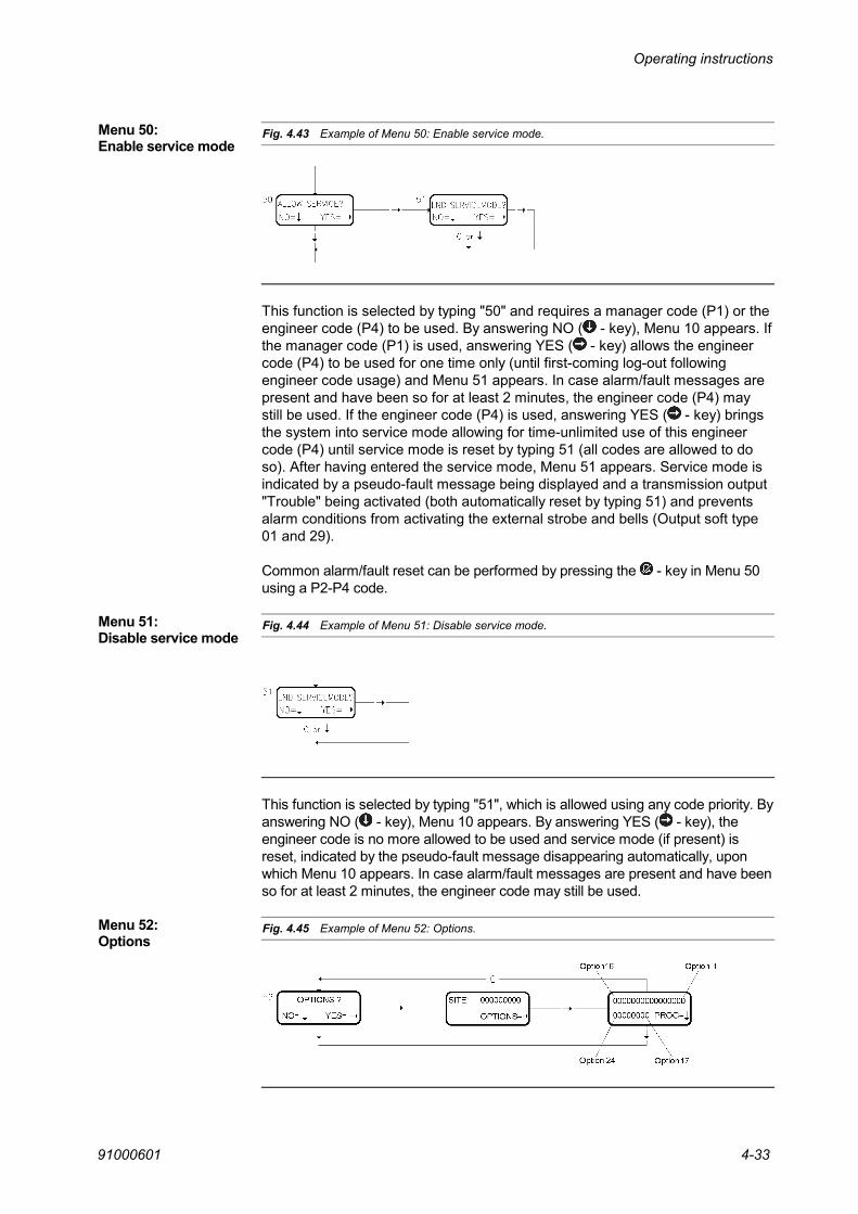
Operating instructions
91000601 4-33
Fig. 4.43 Example of Menu 50: Enable service mode.
This function is selected by typing "50" and requires a manager code (P1) or theengineer code (P4) to be used. By answering NO ( - key), Menu 10 appears. Ifthe manager code (P1) is used, answering YES ( - key) allows the engineercode (P4) to be used for one time only (until first-coming log-out followingengineer code usage) and Menu 51 appears. In case alarm/fault messages arepresent and have been so for at least 2 minutes, the engineer code (P4) maystill be used. If the engineer code (P4) is used, answering YES ( - key) bringsthe system into service mode allowing for time-unlimited use of this engineercode (P4) until service mode is reset by typing 51 (all codes are allowed to doso). After having entered the service mode, Menu 51 appears. Service mode isindicated by a pseudo-fault message being displayed and a transmission output"Trouble" being activated (both automatically reset by typing 51) and preventsalarm conditions from activating the external strobe and bells (Output soft type01 and 29).
Common alarm/fault reset can be performed by pressing the - key in Menu 50using a P2-P4 code.
Fig. 4.44 Example of Menu 51: Disable service mode.
This function is selected by typing "51", which is allowed using any code priority. Byanswering NO ( - key), Menu 10 appears. By answering YES ( - key), theengineer code is no more allowed to be used and service mode (if present) isreset, indicated by the pseudo-fault message disappearing automatically, uponwhich Menu 10 appears. In case alarm/fault messages are present and have beenso for at least 2 minutes, the engineer code may still be used.
Fig. 4.45 Example of Menu 52: Options.
Menu 50:Enable service mode
Menu 51:Disable service mode
Menu 52:Options

Operating instructions
910006014-34
In Menu 52, you can program a number of system options as shown below.
Fig. 4.46 Overview of functions of option bit 1 to option bit 16.
Option bit number: 16 15 14 13 12 11 10 9 8 7 6 5 4 3 2 1
Encrypted communicationDisable hold-up code
Integrated/distributed systemIndustrial/bank set-up
Set-LED indication includes panel zonesCountry selection
Real-time print on top busITYP 04 setting fault
Disable alarm/fault buzzingDisable P2 users to clear tamper alarms
Enable setting fault for battery/mains faultAuto-alarm reset on hold-up detectors
Allow only P4 users to correct clockSpecial bank features
Fig. 4.47 Overview of functions of option bit 17 to option bit 24.
Option bit number: 24 23 22 21 20 19 18 17
Special area setting/unsetting menuAnti Hostage feature and other special features
UnusedUnusedUnusedUnusedUnusedUnused
The following table describes the functions that can be enabled or disabled bythe setting of the option bits. Regarding the Option bits 9, 10 and 11, pleaserefer to the section below the table.
Bit Function0 Special bank features enabled. These features comprise zone and detector
names added to the PC-event mail, auto-arm pre-warning using the buzzer ofRemote Keypads and Access Control Terminals is included with the auto-armzones. Auto-arm pre-warning starts 20 minutes before the auto-arming.
1
1 Special bank features disabled.
0 Allow only P4 users to correct clock enabled. P3 and P2 users may correct with ±2 min.21 Allow only P4 to users to correct clock disabled.
0 Auto-alarm reset on hold-up detectors disabled.31 Auto-alarm reset on hold-up detectors enabled.
0 Setting fault for battery/mains fault enabled.41 Setting fault for battery/mains fault disabled.
Continued …

Operating instructions
91000601 4-35
Bit Function0 The P2 user is able to delete tamper alarms.51 The P2 user cannot delete tamper alarms (only P3 and P4 users).
0 The terminal buzzer will be activated in case of alarm or fault (if not in service mode).6
1 The terminal buzzer is disabled in case of alarm or fault. Entry/exit buzzer willalways work.
0 Input soft type 04 (entry/exit route detectors) will not give a set fault if thedetector is active when a set command is performed. When the exit time isrunning out and the detector is still active an alarm will be created.
7
1 Input soft type 04 (entry/exit route detectors) will give a set fault if the detector isactive when a set command is performed.
0 Print-out will be done on the printer installed on the same bus as the central unit.81 Print-out will be done on the printer installed on the top bus 00.
9 - See the section: Option bits 9, 10, 11 on the next page
10 - See the section: Option bits 9, 10, 11 on the next page
11 - See the section: Option bits 9, 10, 11 on the next page
0 The LED is active when the zones corresponding to the user area are physicallyset. The LED is OFF if the zones are unset or partly set.
12
1 The LED is active when the zones included in the Panel - Zone programming isphysically set. The LED is OFF if the zones are unset or partly set.
0 Bank set-upP0, P1 and P3 users are not allowed to unset zones included in "auto set areas"until such zones are released for unsetting by the auto set function. This means,that if they set their own area during business hour before the normal auto-setperiod, they are not able to unset it again.During auto set, automatic isolation is not allowed. In case of active detectors,forced setting is performed and an alarm condition is released. This is also thecase if forced setting is carried out during manual setting - by pressing the closedlock key instead of the open lock key, when the setting fault list comes up.
13
1 Normal industrial set-up
0 Option 14 is used for selecting whether the system operates as independentsubsystems or as one large system. When the option bit is 0, the keypaddisplays alarm/fault/isolation messages within the complete system, no matterwhich code is used for log-on. The alarm/fault lamps of the keypads reflect thestatus of the keypad-area. Resetting of alarm/fault messages is still allowedwithin the code area only. (single site)
14
1 When the option bit is "1", the keypads display only alarm/fault/isolation messageswithin the area of the intruder code. The alarm/fault lamps reflect the status of thekeypad-area only, independent of the code priority used. (multi-sub sites)
0 Hold-up code function enabled (code + 1 except from codes with 9 as the last digit)15
1 The hold-up code function is disabled
16 0 Non-encrypted communication
1 Encrypted communication.
17 - 22 Unused
23 0 Anti-hostage function and associated functions are disabled
1 Anti-hostage functions and associated functions are enabled. See also Section 1.12
24 0 Normal setting/unsetting procedure.
1 Special area setting/unsetting menu. See the section: Option bit 24 on the next page.

Operating instructions
910006014-36
Option bits 9, 10, 11Two different EPROM's exist for the 95T/90T CU-30): EU1-078.xxxx.xxx andEU2-078.xxxx.xxx.The difference between the EU1 and the EU2 versions is which languages theyare supporting. The different languages are shown in the following table:
Option bit11 10 9
EU1-078.xxxx.xxx version
EU2-078.xxxx.xxx version
0 0 0 English (load default) English (load default)0 0 1 English English
0 1 0 Dutch Czech
0 1 1 Swedish German
1 0 0 Norwegian Portuguese
1 0 1 Spanish Russian
1 1 0 Danish Italian
1 1 1 French Polish
Option bit 23See Section 1.12 for more information about the anti-hostage functions and associatedfunctions.
Option bit 24The special area setting/unsetting procedure used on an 95T RKP is activatedwhen option bit 23 is set to 1. The procedure is described below:
1. Enter the 6-digit code. The display will indicate AREA SET (as normal)
2. Press the Unset button. The display will indicate AREA NO.: _ _ _
3. Enter the required area number.The area with the number entered can only be unset if all zones in thearea belongs to the area of the current user, then only the zones thatare common for both the user and the area will be unset.The display will now indicate for example AREA005 UNSET, if all zonesbelong to the user.
The special area setting procedure used on an 95T RKP corresponds to theabove procedure. If a setting fault occurs, it is possible to isolate as normal.
Site codeIn Menu 52, you can also program a site code. This site code is specially used inconnection with an IMS management system, where the IMS software also isprogrammed with a site code. Only if the two site codes are identically, it ispossible to communicate between the PC and the Intrusion system.
If a Thor Access Control System is connected to the Intrusion System, this sitecode will automatically be programmed with the site code from the access cardsafter a CPU reset and at least one reader initialized.

Operating instructions
91000601 4-37
Fig. 4.48 Example of Menu 53: Output type/timer.
By NO ( ), Menu 54 appears.
This function requires the engineer code (P4) to be used, printer to be connectedand Service mode. The timer allocated to an output type is displayed by pressingthe - key or by overwriting the output type number. By overwriting the 4-digitoutput type number, a menu allowing for changing the allocated timer byoverwriting the 2-digit number (01 - 48) appears. By pressing the - key, the newvalue is stored and the next output type appears. The first 2 digits of the outputtype represents the zone relationship (00 to 16 or 99, where 00 means thecomplete installation, while 99 means, that all output types 00yy to 16yy makesuse of the selected timer), and the next 2 digits represents the output type itself. Byusing the - key at any time, a return to Menu 53 is made. Auto-clear time is 10minutes.
Fig. 4.49 Example of Menu 54: Keypad-zone relation.
By NO ( ), Menu 10 appears.
This function requires the engineer code to be used, printer to be connected andService mode. By typing "1", the zone displayed by the upper line (zone 01 tothe left - zone 16 to the right) belongs to the operating keypad, by typing "0", itdoes not. Keypad 00 is the main control unit, while keypad 01 to 31 are remoteoperating keypads, readers etc. By pressing the - key, the new value is storedand the next element appears. By using the - key, no programming is made;instead the next element is brought forward by using the - key or a jump toanother element is performed by typing the number. By using the - key at anytime, a return to Menu 54 is made. Auto-clear time is 10 minutes.
Only zones common to the keypad and the code used are allowed set/unset.
Please note that Keypad 00 cannot be present.
Menu 53:Output type/timer
Menu 54:Keypad-zone relation

Operating instructions
910006014-38
During the establishment or modification of an expression, it is checked, that validfigures are used for all fields. The validity of each individual input field and theoperand to the right is checked, when the operand is selected (or passed bymeans of the alarm reset key). The validity of the output field including timerallocation is checked, when the timer is selected (or passed by means of the alarmreset key). In case of invalidity, a return to the first digit of the input field (or outputfield) takes place leaving this part of the expression unchanged.
Fig. 4.50 Example of Menu 57: Alarm Functions.
The validity of a complete expression is checked when it is stored by means ofthe - key. In case of invalidity - inconsistency between input field and operand- the complete expression is returned unchanged.
The keys of the keypad have the following functions:
Performs a jump back to the alarm functions select menuleaving the expression, in which it was pressed, unchanged.
Performs a jump from the first window (first ½ expression) tothe next window (second ½ expression) and further on to thegeneral new number select menu.
Is used to store the expression in either one of the twowindows.
Is used as logical OR operand. Can also be used to move thecursor from one operand to the next (will leave the input field as000) to come to the Output address field. If the key is usedwithin an input field, the operand to the right is changedaccordingly and a jump to the first digit of the next input field(or back to the first input field - within the first ½ expressionwindow only) takes place.
Menu 57:Alarm functions

Operating instructions
91000601 4-39
Is used as logical AND operand. Can also be used to move thecursor from one operand to the next (will leave the input field as000) to come to the Output address field. If the key is usedwithin an input field, the operand to the right is changedaccordingly and a jump to the first digit of the next input field (orback to the first input field - within the first ½ expression windowonly) takes place.
Makes the cursor step one position to the right and back to thefirst digit within each window (½ expression).
Numerical keys (0 to 9) are used for entry of numbers in inputfields or in output/timer fields only. If they are used in anoperand field, a jump back to the first digit of the input field tothe left occurs.
Only available in connection with 90T CU-30 and 95T CU-30.
It is possible to correct the clock, if it goes to fast or too slowly. It can be correctedwith max. +/- 999 seconds per week. Applies only to hardware without RTC-clock.
Fig. 4.51 Example of Menu 58: Adjust Clock.
This menu is used for resetting the CU from the keypad. When the menu isactivated then the output type 48 (CPU reset) is activated for 5 s before the resettakes place. Only P4 codes are allowed to use this menu and the CU must be inservice mode.
Fig. 4.52 Example of Menu 59: Reset.
Menu 58:Adjust Clock
Menu 59:Reset
The first digit of the correction factorindicates + or -, where 0 = - and 1 = +.

Operating instructions
910006014-40
4.6 Autoset programmingPriority 2 and Priority 4 codes can use the Auto Set programming menus. Theprogrammed times can be printed out by Menu 28, Print Setup.
This function is used to create, change or delete a week program for an area. Aweek program has 7 normal days (Monday = day1) and two special days (day 8and day 9) referring to the holiday list.
Fig. 4.53 Example of Menu 55: Edit area week programs.
One digit is keyed in for the area number 1- 8, for which this week program isprogrammed. After that day1 is displayed with the starting time 00:00. The firstperiod will then be from 00:00 to xx:x0 where x is keyed in. The xx:x0 time willafter automatically be transferred to the starting time of the next period forday1 to avoid that the user makes a time program with holes or overlappingtimes. One day is finished when 24:00 is programmed for the end-time and thenext day2 is shown in the display. If the - key is used in this position a copy ofthe day before will be made for this day.
If one of the menus is left by the - key, the programming of time programs isleft without storing the data for this week program (area) number.
By keying in 00:00 to 00:00 the week program is deleted.
It is possible to program in 10 minutes intervals. That means that it is onlynecessary to key in 3 digits. The last digit is always 0.
The FNC field is programmed with the function for the area. One of the followingfunctions can be allocated to the time periods for area week time program.
Setting the area at the beginning of the period or setting at the end of the periodif delay has been requested from one of the Remote keypads. Delay can only berequested once
Setting the area at the beginning of the period.
Setting the area at the beginning of the period and enabling manual unsetting atthe end of the period.
Unsetting the area at beginning of the period.
No change.
At the beginning of the period and each 10 minutes in the period, it is verified thatthe area is set. If the area is not set, an alarm is generated on an input addresscorresponding to the area number. There is no reaction if the area is set.
Menu 55: Edit areaweek programs
FNC 1
FNC 2
FNC 3
FNC 4
FNC 5
FNC 6

Operating instructions
91000601 4-41
It is possible to delay the function in the pre-warning period. If this is the case, theverification will only take place at the end of the period.
When the function becomes active and the area is unset, then a timer is started(timer 18 –duration in minutes) and when the timer expires, the area isautomatically set. 10 minutes before the automatic setting the pre-warningoutput type is activated, as normal.If the area is unset when the function is active, the timer will be started asabove.It is possible to delay the automatic setting (when the pre-warning is active) bymeans of Menu 14. The setting is then delayed for the programmed time (Timer18 – delay in minutes).
Operates as FNC 1. However, if there are any active detectors in the area to beset, the setting is cancelled and a set fault message is sent.This message will contain a list of all the detectors that where active when theAuto-Arm function would have set the area, maximum 100. The message issent to following devices: Alarm / event transmitter, INCOM, GPI Host interfaceand Modem interface.
Operates as FNC 2. However, if there are any active detectors in the area to beset, the setting is cancelled and a set fault message is sent.This message will contain a list of all the detectors that where active when theAuto-Arm function would have set the area, maximum 100. The message issent to following devices: Alarm / event transmitter, INCOM, GPI Host interfaceand Modem interface.
Allows manual unsetting at the start of the period. If the area is not unset at theend of the period, the area+1 is set automatically.
Allows manual setting and unsetting at the start of the period, but only when thearea is unset when the period starts.
Fig. 4.54 Example of Menu 56: Edit holiday list.
This function is used to create a holiday list that refers to the above programmedweek programs for the day8 and day9.
The list has max. 25 periods where start date and end date are programmed foreach period. A period includes the start date and end date.
FNC 7
FNC 8
FNC 9
FNC 10
FNC 11
Menu 56: Editholiday list

Operating instructions
910006014-42


Denmark United Kingdom France NetherlandsHI SEC International
Marielundvej 16DK- 2730 HerlevDenmark
Tel.: +45 44 50 78 00Fax: +45 44 50 78 01E-mail: dk @ hisec.com
HI SEC International
4B Victoria AvenueCamberley Surrey GU15 3HXUnited Kingdom
Tel.: +44 (0) 1276 679 950Fax: +44 (0) 1276 679 949E-mail: gb @ hisec.com
HI SEC International
ZAC de Nanteuil12, rue Jules FerryF-93561 Rosny sous BoisFrance
Tel.: +33 (0) 1 48 12 90 10Fax: +33 (0) 1 48 12 90 20E-mail: fr @ hisec.com
HI SEC International
Populierendreef 968BNL-2272 HW VoorburgHolland
Tel.: +31 (0) 70 386 1103Fax: +31 (0) 70 387 4095E-mail: nl @ hisec.com
Spain Germany USAHI SEC International
C/. Ávila, 48-503° Planta, local G-HE-08005 BarcelonaSpain
Tel.: +34 93 300.46.95Fax: +34 93 485.60.78E-mail: hisec @ ciberset.com
HI SEC International
Westerholtstraße 6D-46119 OberhausenGermany
Tel.: +49 (0) 208 - 611193Fax: +49 (0) 208 - 6290299E-mail: ghr @ hisec.com
HI SEC International
6829 K Avenue,Suite 101Plano, TX 75074USA
Tel.: +1 (972) 509 7744Fax: +1 (972) 509 0144E-mail: jje @ hisec.com