three-channel non-force magnetic...
TRANSCRIPT
THREE-CHANNEL NON-FORCE MAGNETIC MICROSCOPES. I. Bondarenko1, A. A. Shablo1, P. P. Pavlov1, and N. Nakagawa2
Institute for Low Temperature Physics and Engineering of National Academy of Ukraine,Kharkov, Ukraine
2Center for Nondestructive Evaluation, Iowa State University, Ames, IA 50011, USA
ABSTRACT. The development of a scanning magnetic microscope (MM) without appreciableapplied forces or magnetic excitations on specimens is presented. The magnetic microscope isintended to measure weak magnetic field distributions near the object surface at micron and sub-micron scales. Specifically, the MM consists of three measurement units with respective outputchannels. The first channel uses a special fluxgate magnetometer as a field detector, and is designedfor magnetic study of a specimen surface at room temperature (T=300K), with a magnetic sensitivityof 10"9T, at a spatial resolution of 10u,m in a scan area of 10x10 mm. The second channel uses aHTSC SQUID and a ferromagnetic flux concentrator, and is intended for detailed study of a room-temperature object at the sensitivity of 10'12 T with 0.1-1 Jim resolutions. The third component alsouses the SQUID-concentrator combination, but is intended for detailed study of the object at liquid-nitrogen temperature (T=77 K), covering the area of lOOxlOOjum.
INTRODUCTION
Four types of magnetic microscopes (MM) are well known to date:magnetic force microscope (MFM);magnetic SQUID microscope (MSM);
- magnetic Hall microscope (MHM)magnetic eddy current microscope (MECM).
Each of the MM classes distinguishes itself by the type of magnetic detector that scansover a testing object (TO) surface.
There is an extremely small needle in design of MFM [1] manufactured frommagnetic hard material. The attractive force of a needle to TO can be measured and themeasurement gives the information about the value of the TO magnetic moment (M) at agiven location of the probe. The attractive force depends on M and the distance (f) betweenthe TO and needle. It is therefore necessary to choose t values to be tens and hundreds ofangstroms in order to achieve the spatial MFM resolution of tens of angstroms. In somecases the said force interaction results in irreversible changes of TO properties. In reality,the scanning range by MFM often becomes the order of microns for actual research timescales.
The MSM detector [2] is either a SQUID interferometer or an extremely small (ofsome micron diameter) coil of a flux transformer coupled with a SQUID. This detector, incomparison with MFM detectors, has no force or magnetic effect on TO. While it isadvantageous as being a really passive detector, it has a disadvantage in terms of spatialresolution. The detector size and the need for thermal insulation prevent the detector fromapproaching the object in angstrom distances. Thus, MSM cannot achieve high spatial
CP657, Review of Quantitative Nondestructive Evaluation Vol. 22, ed. by D. O. Thompson and D. E. Chimenti© 2003 American Institute of Physics 0-7354-0117-9/03/$20.00
923

resolutions characteristic to MFM, especially in "warm" (T-300K) TO cases. Indeed, theMSM spatial resolution is typically not better than some microns. The rather large distancebetween the MSM detector and the TO is partially compensated by high SQUID magneticsensitivity. However, there is a significant trade-off between very high SQUID magnetic-flux sensitivities and desirable minimum sizes of the detector. Consequently, MSMdetectors have, as a rule, sensitivities to a local TO field of not better than 10~9 to 10"10 T.Because of the significant overall dimensions and weight of the SQUID cryogenicequipment, the TO should be moved instead of detector. Also as a rule, MSM allows tomeasure vertical component of a magnetic flux created by TO.
The MHM probe is an extremely small semi-conducting structure of a triangularshape, its acute angle being pointed toward the TO. This probe is essentially passive, haslower magnetic sensitivities than that of MSM, and can approach the TO surface withsome micron lift off with the corresponding spatial resolution of TO. MECM uses aninductive coil with a ferrite core having a narrow slot, and measures horizontalcomponents of alternating magnetic fields produced by induced eddy current within TO. Itdoes not work for DC field measurements.
The present article describes a principle of operation and design of a new threechannel MM, consisting of two improved HTc SQUID measuring channels and of auncooled channel based on a special fluxgate magnetometer. This MM allows to studyboth "warm" and "cold" objects, at temperatures down to liquid nitrogen (77K). Principaldistinctive features of the new MM are:
- application of the ferromagnetic concentrator of a magnetic flux between SQUIDand TO [3] and also in a fluxgate magnetometer;
- usage of an special fluxgate sensor having sufficiently high sensitivity to amagnetic field of dipole sources with high spatial resolution.
The MM uses ferromagnetic needles as the field concentrator that bridges fields between aTO surface point and the SQUID aperture. Since it allows the use of highly sensitiveSQUIDs of a finite size, the MM achieves both high resolution and high sensitivitiessimultaneously. The new MM allows measurement of a vertical component of a TOmagnetic flux. In what follows, we summarize the advantages of our MM:
better magnetic sensitivity than traditional MSM and MHM;better spatial resolution than traditional MSM;
- possibility, in principal, to measure all three components of the object magneticfield simultaneously, unlike MFM;absence of appreciable force influence on the object unlike MFM;
- possibility to measure alternating and direct magnetic field unlike MECM.
THE DESCRIPTION OF A THREE CHANNEL MM DESIGN
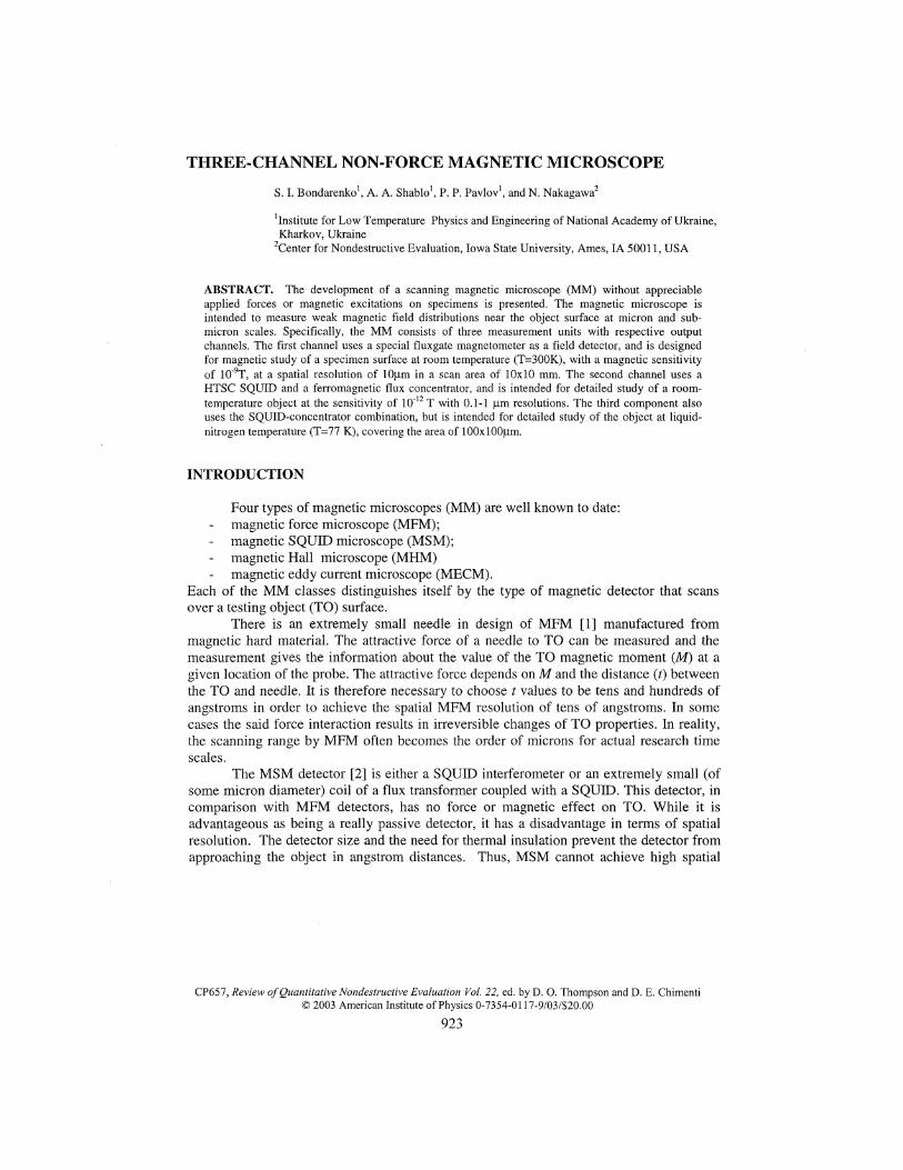
The schematic of the MM channels and the basis units is given in Fig. 1. Theexternal view of MM is shown in Fig. 2. The channels located in the middle and on theright are used for a TO study at T-300K, while the channel on the left side is used for aTO testing at T-77K. The first two channels contain the two-axis motion-controlledscanning tables. The specimen holder is mounted on the scanner table as shown, andplaced under either a central fluxgate channel or a right SQUID channel.
924

FIGURE 1. Design Schematic of Magnetic Microscope, including EC-Electronic Converter; PA- Preamplifier; ADC 16-Analog Digital Converter 16-bit Resolution;DDSM-Drive Device Stepper Motors; SM-Stepper Motor.
toON
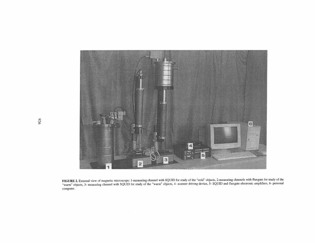
FIGURE 2. External view of magnetic microscope: 1-measuring channel with SQUID for study of the "cold" objects, 2-measuring channels with fluxgate for study of the"warm" ohiects 3- measuring channel with SQUID for study of the "warm" objects, 4- scanner driving device, 5- SQUID and fluxgate electronic amplifiers, 6- personal"warm" objects, 3- measuring channel with SQUID for study of th<computer.
During a TO study at T=300K, a fluxgate channel may be used first, that allowspreliminary examination of a 10x10 mm area with spatial resolution up to 10 microns andwith sensitivity up to 10"9 Tesla. After finding a region of the most interest, the TO may bemoved under the right SQUID channel, which performs imaging of a 100x100 micronsquare area at the 0.1 to 1 micron resolution and at the sensitivity up to 10"12 Tesla. The HTcSQUID is manufactured from a high temperature superconductor YBa2Cu2O7_5 and has anoperation temperature close to 77K.
The left-hand channel has also HTc SQUID with the ferromagnetic concentrator.The detector characteristics in terms of sensitivity and spatial resolution are identicalbetween the left and right SQUID channels. In the left channel, however, the TO holder isinserted into the nitrogen cryostat from above. The 2D-scanner is mounted on top of thecryostat. For magnetic shielding, the channels are supplied with three layers of permalloyshields which suppresses Jow frequency magnetic fields by more than 100 times and highfrequency by more than 1000 times.
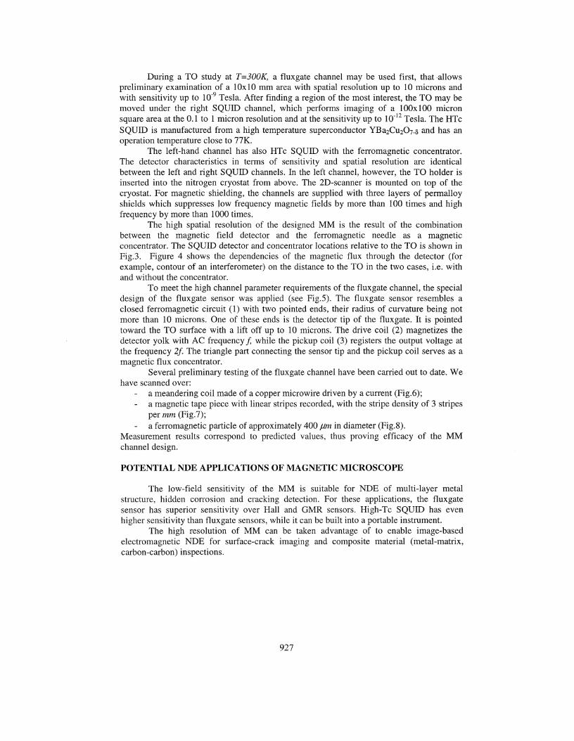
The high spatial resolution of the designed MM is the result of the combinationbetween the magnetic field detector and the ferromagnetic needle as a magneticconcentrator. The SQUID detector and concentrator locations relative to the TO is shown inFig.3. Figure 4 shows the dependencies of the magnetic flux through the detector (forexample, contour of an interferometer) on the distance to the TO in the two cases, i.e. withand without the concentrator.
To meet the high channel parameter requirements of the fluxgate channel, the specialdesign of the fluxgate sensor was applied (see Fig.5). The fluxgate sensor resembles aclosed ferromagnetic circuit (1) with two pointed ends, their radius of curvature being notmore than 10 microns. One of these ends is the detector tip of the fluxgate. It is pointedtoward the TO surface with a lift off up to 10 microns. The drive coil (2) magnetizes thedetector yolk with AC frequency/ while the pickup coil (3) registers the output voltage atthe frequency 2f. The triangle part connecting the sensor tip and the pickup coil serves as amagnetic flux concentrator.
Several preliminary testing of the fluxgate channel have been carried out to date. Wehave scanned over:
a meandering coil made of a copper microwire driven by a current (Fig.6);- a magnetic tape piece with linear stripes recorded, with the stripe density of 3 stripes
per mm (Fig.7);a ferromagnetic particle of approximately 400 jLim in diameter (Fig.8).
Measurement results correspond to predicted values, thus proving efficacy of the MMchannel design.
POTENTIAL NDE APPLICATIONS OF MAGNETIC MICROSCOPE
The low-field sensitivity of the MM is suitable for NDE of multi-layer metalstructure, hidden corrosion and cracking detection. For these applications, the fluxgatesensor has superior sensitivity over Hall and GMR sensors. High-Tc SQUID has evenhigher sensitivity than fluxgate sensors, while it can be built into a portable instrument.
The high resolution of MM can be taken advantage of to enable image-basedelectromagnetic NDE for surface-crack imaging and composite material (metal-matrix,carbon-carbon) inspections.
927
FIGURE 3. The schematic of the high-Tc SQUID detector with flux concentrator (2) for a measurement of thesurface magnetic field of the sample (1), 3-external wall of the nitrogen cryostat, 4-vacuum, 5-interferometerweak link, 6-HF interferometer, 7-heat exchanger, 8-inner wall of the nitrogen cryostat, 9-liquid nitrogen, S-small vacuum slot.
rFIGURE 4. Dependencies of the magneticflux (<£) through the interferometer on itsdistance (z) to a magnetic point source in thesample without the concentrator (1) and withthe concentrator (2).
FIGURE 5. The schematic of the fluxgatedetector: 1- ferromagnetic circuit; 2-excitation coil; 3-coil for generating theoutput voltage (Vex); 4-testing object.
928

18020:8
FIGURE 6. A MM image of the vertical component of a magnetic field over two micro wires with an oppositedirect current I , wire diameter of 70 |im, and distance of 80 |im between the wires.
FIGURE 7. A MM image of the vertical component of a magnetic field over a tape (band) with the linearmagnetizations (3 Y-lines/mm along the X axis).
929

II p i
FIGURE 8. A MM image of the vertical component of a magnetic field over a small magnetic particle ofapproximately 400 (am in diameter.
The combined capabilities of the low-field sensitivity, high resolution, and no forceproperties of MM enable new classes of NDE applications. The potentials includebiomedical magnetic-field detection (functional imaging via blood-flow detection, brain-wave mapping), and NDE of fluid specimen containing magnetic particles.
ACKNOWLEDGMENTS
The authors wish to express their gratitude to STCU Foundation for support of thework (Project #2266).
REFERENCES
1. Dan Dahlberg E., Proksch R., Magnetic microscopies: the new additions, /. of Magn.andMagn. Mat., 200 , 720-728 (1999).
2. Vu L.N., Harlingen V. IEEE Trans. Appl Sypercond., 3, 1918, (1993).3. Bondarenko S.I., Shablo A.A.,, "High-Tc SQUIDs with an antenna for a magnetic
microscope" in Non-linear Electromagnetic Systems, edited by V. Kose and J. Sievert(Eds).,publisher, JOS Press, 1998, pp. 91-94.
930