three-dimensional infrared metamaterial with...
TRANSCRIPT
Three-Dimensional Infrared Metamaterial with AsymmetricTransmissionGeorge Kenanakis,*,† Aggelos Xomalis,†,‡ Alexandros Selimis,† Maria Vamvakaki,†,‡ Maria Farsari,†
Maria Kafesaki,†,‡ Costas M. Soukoulis,†,§ and Eleftherios N. Economou†
†Institute of Electronic Structure and Laser, Foundation for Research & Technology-Hellas, N. Plastira 100, 70013, Heraklion, Crete,Greece‡Department of Materials Science and Technology, University of Crete, 710 03 Heraklion, Crete, Greece§Ames Laboratory-USDOE and Department of Physics and Astronomy, Iowa State University, Ames, Iowa 50011, United States
*S Supporting Information
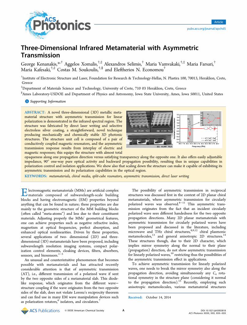
ABSTRACT: A novel three-dimensional (3D) metallic meta-material structure with asymmetric transmission for linearpolarization is demonstrated in the infrared spectral region. Thestructure was fabricated by direct laser writing and selectiveelectroless silver coating, a straightforward, novel techniqueproducing mechanically and chemically stable 3D photonicstructures. The structure unit cell is composed of a pair ofconductively coupled magnetic resonators, and the asymmetrictransmission response results from interplay of electric andmagnetic responses; this equips the structure with almost totalopaqueness along one propagation direction versus satisfying transparency along the opposite one. It also offers easily adjustableimpedance, 90° one-way pure optical activity and backward propagation possibility, resulting thus in unique capabilities inpolarization control and isolation applications. We show also that scaling down the structure can make it capable of exhibiting itsasymmetric transmission and its polarization capabilities in the optical region.
KEYWORDS: metamaterials, chiral media, split-cube resonators, asymmetric transmission, direct laser writing
Electromagnetic metamaterials (MMs) are artificial complexmaterials composed of subwavelength-scale building
blocks and having electromagnetic (EM) properties beyondanything that can be found in nature; these properties are duemainly to the geometric structure of the MM building blocks(often called “meta-atoms”) and less due to their constituentmaterials. Adjusting properly the MMs’ geometrical features,one can achieve properties such as negative refractive index,magnetism at optical frequencies, perfect absorption, andenhanced optical nonlinearities. Driven by these properties,several applications of two- dimensional (2D) and three-dimensional (3D) metamaterials have been proposed, includingsubwavelength resolution imaging systems, compact polar-ization control elements, cloaking devices, filters, absorbers,sensors, and biosensors.1−5
An unusual and counterintuitive phenomenon that becomespossible with metamaterials and has attracted recentlyconsiderable attention is that of asymmetric transmission(AT), i.e., different transmission of a polarized wave if sentby the two opposite sides of a metamaterial slab. This diode-like response, which originates from the different wave−structure coupling if the wave originates from the two oppositesides of the slab, does not violate Lorenz’s reciprocity theoremand can find use in many EM wave manipulation devices suchas polarization rotators,6 isolators, and circulators.7
The possibility of asymmetric transmission in reciprocalstructures was discussed first in the context of 2D planar chiralmetamaterials, where asymmetric transmission for circularlypolarized waves was observed.8−11 This asymmetric trans-mission originates from the fact that an incident circularlypolarized wave sees different handedness for the two oppositepropagation directions. Many 2D planar metamaterials withasymmetric transmission for circularly polarized waves havebeen proposed and discussed in the literature, includingmicrowave and THz chiral structures,8,9,12 chiral plasmonicmetamolecules,13 and general anisotropic 2D structures.14
These structures though, due to their 2D character, whichimplies mirror symmetry along the normal to their plane(propagation) direction, do not show asymmetric transmissionfor linearly polarized waves,10 restricting thus the possibilities ofthe asymmetric transmission effect in applications.To achieve asymmetric transmission for linearly polarized
waves, one needs to break the mirror symmetry also along thepropagation direction, avoiding simultaneously any C4 rota-tional symmetry in the structure plane (considering it normalto the propagation direction).15 Recently, employing suchanisotropic metamolecules, various metamaterial structures
Received: October 14, 2014
Article
pubs.acs.org/journal/apchd5
© XXXX American Chemical Society A DOI: 10.1021/ph5003818ACS Photonics XXXX, XXX, XXX−XXX

showing asymmetric transmission for linearly polarized waveshave been proposed and demonstrated, and the conditionsrelating asymmetric transmission and structure asymmetrieshave been discussed in detail.15−19
Most of the AT structures demonstrated to date arestructures based on the planar bilayer conductor configuration;that is, the unit cell is formed by a pair of planar conductors,electromagnetically coupled. Transmission asymmetry origi-nates from the asymmetric coupling of electric dipolar resonantmodes of the two planar conductors. Despite the ease offabrication, using such planar structures limits the possibilitiesoffered by fully 3D volumetric structures, which allow a muchlarger variety of structure designs, allowing much moresubwavelength-scale metamaterial resonators and larger flexi-bility in the coupling between adjacent resonators; not onlyelectromagnetic coupling but coupling via electric-currentconnections is allowed. Moreover, they allow asymmetrictransmission to be generated due to asymmetric coupling ofmagnetic rather than electric dipole resonances.The involvement of magnetic resonators, besides electric
resonators, in the AT effect offers the potential to adjust at willthe structure impedance, matching for example the free spaceimpedance and achieving higher transmission values. Moreover,it offers the potential to combine AT with backwardpropagation, allowing, for example, backward propagationalong one direction versus forward propagation in the oppositedirection, leading to a peculiar structure response.In this work we demonstrate asymmetric transmission
generated by magnetic resonance coupling in a 3D volumetricstructure based on two perpendicular split-cube resonators(SCRs); see Figure 1. The structure was fabricated by directlaser writing (DLW)20,21 and selective silver coating,22,23 atechnique able to provide fully 3D structures with deep-subwavelength resolution. It operates in the middle infrared(15−40 THz), a frequency region of significant technologicalinterest, where the requirement for EM wave controlcomponents is still high, despite substantial recent develop-ments. Our structure, which exhibits asymmetric transmissionfor linear polarization only (and not for circular), while it isquite transparent along one propagation direction, showsalmost total isolation along the opposite direction, providingunique possibilities in polarization isolation applications. To
achieve such an isolation response (zero vs high transmission),both the electric and magnetic responses of the split-cuberesonator components of the structure were exploited. Thisinvolvement of both electric and magnetic resonances equipsthe structure also with the possibility of one-way 90° pureoptical activity, offering additional capabilities for the control ofthe light polarization.4,24
In what follows we present the structure design (Section 2),the fabrication (Section 3, detailed in the SupportingInformation), and the methods employed to analyze theelectromagnetic response of the structure, both theoreticallyand experimentally (Section 4). In Section 5 we present theresults of the electromagnetic characterization of the structure,which include reflection measurements and simulationscombined with transmission simulation and analysis, followedby a detailed discussion of our structure capabilities. Finally, inSection 6 we discuss a miniaturized, nanometer-scale version ofthe structure, which offers optical (at 750 nm wavelength)asymmetric transmission for linearly polarized light. The paperends with our conclusions.
■ THE DESIGN
The unit cell of the 3D metamaterial design employed in thepresent study is shown in Figure 1. It consists of two split-cuberesonator structures rotated by 90° with respect to each otheralong the z (propagation)-direction. The geometrical structureparameters for the structure as fabricated and characterizedexperimentally are detailed in the caption of Figure 1.As can be seen, the structure lacks mirror symmetry along
the x-, y-, and z-directions as well as C4 rotational symmetry inthe x−y plane. It consists of two conductively coupled identicalmagnetic resonators with the back one (along z) rotated 90°with respect to the front one. According to the literature,17,18
structures of this symmetry are expected to allow asymmetrictransmission for linearly polarized waves only. This comes fromasymmetric cross-polarization conversion of a linearly polarizedwave incident on the two opposite sides of the slab (along thez-direction) and depends strongly on the polarization of theincident wave in the x−y plane.
Figure 1. (a) Schematic of the unit cell of the 3D SCR metamaterials under consideration. The dimensions of the fabricated structure are ax = ay =8.0 μm, az = 9.1 μm, w1 = 600 nm, and w2 = 850 nm, respectively. The wave propagation is along the z-direction. (b) Top view of the SEM image ofthe 3D SCR metamaterials under consideration, recorded at 15 kV. The magnification scale can be seen below the SEM image.
ACS Photonics Article
DOI: 10.1021/ph5003818ACS Photonics XXXX, XXX, XXX−XXX
B
■ STRUCTURE FABRICATIONAs was mentioned in the introduction, our structure wasfabricated by direct laser writing followed by electroless silverplating. DLW by multiphoton polymerization is a 3D printingtechnology that allows the fabrication of 3D structures withresolution below 100 nm. Briefly, the beam of an ultrafast laseris tightly focused inside the volume of a transparent andphotosensitive monomer, causing it to absorb two or morephotons and polymerize locally. By moving the beam in threedimensions inside the photopolymer volume, one can fabricate3D structures of great accuracy. The photosensitive materialused for the fabrication is an organic−inorganic composite,produced by the addition of methacryloxypropyl trimethox-ysilane (MAPTMS) to zirconium n-propoxide. 2-(Dimethylamino)ethyl methacrylate (DMAEMA), acting as ametal-binding moiety, was also added and copolymerized withMAPTMS upon photopolymerization. Michler’s ketone (4,4-bis(diethylamino)benzophenone, BIS) was used as the photo-initiator. Further information on the fabrication technique andthe photosensitive material synthesis can be found in theSupporting Information.
■ ELECTROMAGNETIC CHARACTERIZATIONThe experimental EM characterization of the structurediscussed here was performed in the frequency region 15−40THz, through reflection measurements, performed using aBruker Vertex 70v Fourier-transform infrared spectrometerwith a collimated beam, attached to a Bruker Hyperion 2000infrared microscope and two linear ZnSe grid polarizers.The results of the measurements were compared in all cases
with corresponding reflection simulations. For these, we used acommercial three-dimensional full-wave solver (CST Micro-wave Studio, Computer Simulation Technology GmbH,
Darmstadt, Germany) based on the finite element method.We considered in the simulations a single unit cell, as shown inFigure 1, with periodic boundary conditions along the x- and y-directions, while an incident plane wave propagating along thez-direction was used to excite the structure. For modeling themetallic parts of the structure (silver; yellow color in Figure 1)we considered a lossy-metal model with a conductivity of σAg=5.71 × 10⁶ S/m, in agreement with previous conductivitymeasurements.22
■ RESULTS AND DISCUSSION
Reflection Measurements. Since the 3D SCR structurewas fabricated on glass, which is not transparent in the far-infrared region of interest, we characterized the structureexperimentally by measuring the reflection rather than thetransmission coefficients. The transmission coefficients wereconcluded indirectly, through simulations. Thus, for a linearlypolarized incident wave four reflection components weremeasured, Rxx, Rxy, Ryx, and Ryy, where the first and secondlower indices indicate the output and input signal polarizations,respectively, e.g., Rxy = Ex
r/Eyi , where Ey
i is the incident y-polarized electric field and Ex
r is the reflected x-polarized electricfield.25
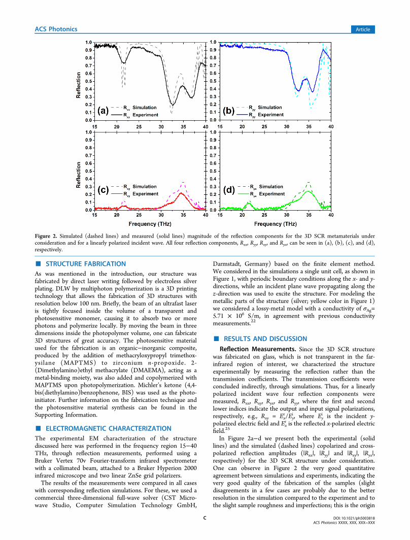
In Figure 2a−d we present both the experimental (solidlines) and the simulated (dashed lines) copolarized and cross-polarized reflection amplitudes (|Rxx|, |Ryy| and |Rxy|, |Ryx|,respectively) for the 3D SCR structure under consideration.One can observe in Figure 2 the very good quantitativeagreement between simulations and experiments, indicating thevery good quality of the fabrication of the samples (slightdisagreements in a few cases are probably due to the betterresolution in the simulation compared to the experiment and tothe slight sample roughness and imperfections; this is the origin
Figure 2. Simulated (dashed lines) and measured (solid lines) magnitude of the reflection components for the 3D SCR metamaterials underconsideration and for a linearly polarized incident wave. All four reflection components, Rxx, Ryy, Rxy, and Ryx, can be seen in (a), (b), (c), and (d),respectively.
ACS Photonics Article
DOI: 10.1021/ph5003818ACS Photonics XXXX, XXX, XXX−XXX
C
also of the not-well-resolved experimental double dip ofsimulated Rxx around 21.5 THz; the double character of thedip is due to the coupling (leading to splitting) of the magneticresonant modes of the two SCRs of the unit cell, as we willdiscuss later). This very good agreement between simulationsand experiments also allows us to base the subsequentcalculations and analysis on the simulation results.Transmission Properties: Asymmetric Transmission.
In order to study wave propagation and transmission inanisotropic structures like the one discussed here, usually thetransmission matrix is employed, T⃡, which connects thetransmitted with the incident fields as follows:
=⎛
⎝⎜⎜
⎞
⎠⎟⎟
⎛⎝⎜⎜
⎞⎠⎟⎟⎛
⎝⎜⎜
⎞
⎠⎟⎟
E
E
T T
T T
E
E
x
y
xx xy
yx yy
x
y
t
t
i
i(1)
In eq 1 propagation of an incident plane wave along the z-direction is considered, and Ex
t ,Eyt denote the x and y
components of the transmitted electric field, respectively.By definition, asymmetric transmission, often symbolized as
Δ, is the difference in the transmittance (transmitted intensitydivided by the incident intensity) for waves propagating alongtwo opposite directions (in our case the forward (positive) andbackward (negative) z-direction), i.e.,
Δ = | | − | |T Tf 2 b 2 (2)
with |T|2 = |Et|2/|Ei|2 = (|Ext |2 + |Ey
t |2)/|Ei|2, where thesuperscripts f and b denote the forward and backward z-direction, respectively.Let us consider the incident wave to be a linearly polarized
wave polarized along the x-direction, i.e., Eyi = 0. The
transmitted wave then will have in general both x and ycomponents, and the normalized transmitted intensity will be |T|2 = |T(x)|
2 = |Txx|2 + |Tyx|
2. (For a y-polarized incident wave itwill be |T|2 = |T(y)|
2 = |Tyy|2 + |Txy|
2.)In systems containing only reciprocal materials, like the one
studied here, the transmission matrix for the backwardpropagation direction is connected to the transmission matrixfor the forward direction as follows:15
=−
−
⎛
⎝⎜⎜
⎞
⎠⎟⎟
⎛
⎝⎜⎜
⎞
⎠⎟⎟
T T
T T
T T
T T
xx xy
yx yy
xx yx
xy yy
b b
b b
f f
f f(3)
Thus, the asymmetric transmission for an x-polarized incidentwave becomes
Δ = Δ= | | + | | − | | − | |
= | | − | |
T T T T
T T
x
xx yx xx yx
yx xy
( )
f 2 f 2 b 2 b 2
f 2 f 2(4)
(For a y-polarized incident wave, Δ = Δ(y) = |Txyf |2 + |Tyy
f |2 − |Txyb |2 −|Tyy
b |2 = |Txyf |2 −|Tyx
f |2 = −Δ(x).)Equation 4 shows that, in the case of reciprocal systems,
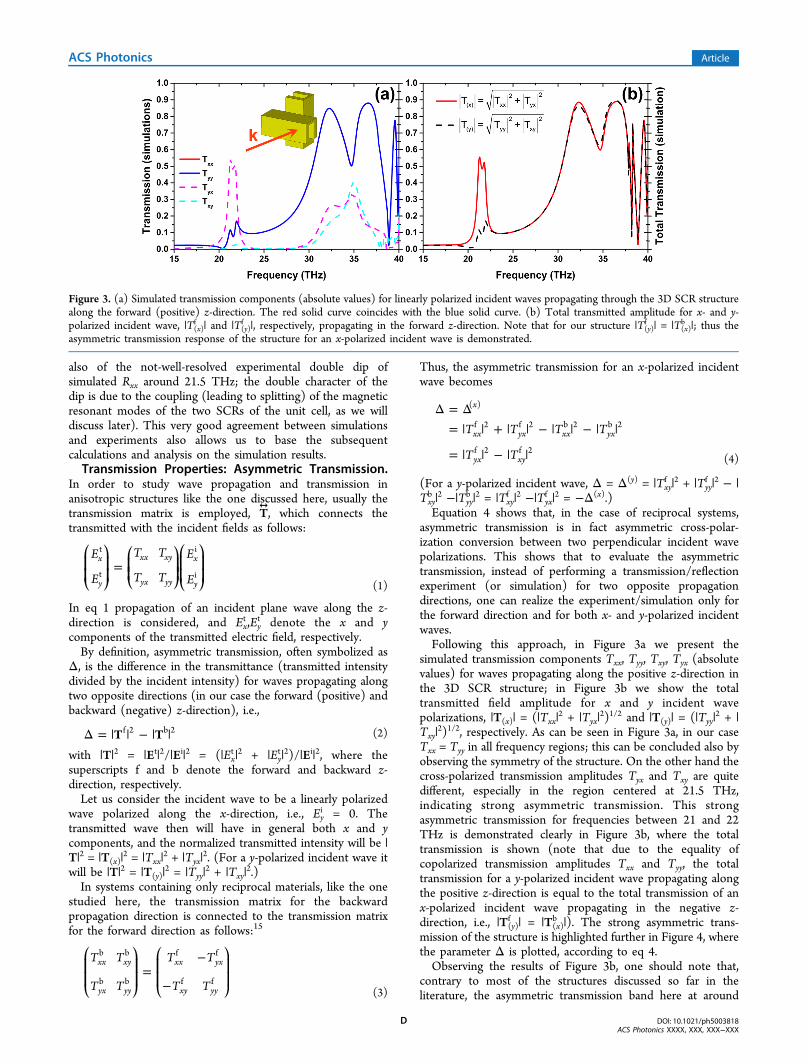
asymmetric transmission is in fact asymmetric cross-polar-ization conversion between two perpendicular incident wavepolarizations. This shows that to evaluate the asymmetrictransmission, instead of performing a transmission/reflectionexperiment (or simulation) for two opposite propagationdirections, one can realize the experiment/simulation only forthe forward direction and for both x- and y-polarized incidentwaves.Following this approach, in Figure 3a we present the
simulated transmission components Txx, Tyy, Txy, Tyx (absolutevalues) for waves propagating along the positive z-direction inthe 3D SCR structure; in Figure 3b we show the totaltransmitted field amplitude for x and y incident wavepolarizations, |T(x)| = (|Txx|
2 + |Tyx|2)1/2 and |T(y)| = (|Tyy|
2 + |Txy|
2)1/2, respectively. As can be seen in Figure 3a, in our caseTxx = Tyy in all frequency regions; this can be concluded also byobserving the symmetry of the structure. On the other hand thecross-polarized transmission amplitudes Tyx and Txy are quitedifferent, especially in the region centered at 21.5 THz,indicating strong asymmetric transmission. This strongasymmetric transmission for frequencies between 21 and 22THz is demonstrated clearly in Figure 3b, where the totaltransmission is shown (note that due to the equality ofcopolarized transmission amplitudes Txx and Tyy, the totaltransmission for a y-polarized incident wave propagating alongthe positive z-direction is equal to the total transmission of anx-polarized incident wave propagating in the negative z-direction, i.e., |T(y)
f | = |T(x)b |). The strong asymmetric trans-
mission of the structure is highlighted further in Figure 4, wherethe parameter Δ is plotted, according to eq 4.Observing the results of Figure 3b, one should note that,
contrary to most of the structures discussed so far in theliterature, the asymmetric transmission band here at around
Figure 3. (a) Simulated transmission components (absolute values) for linearly polarized incident waves propagating through the 3D SCR structurealong the forward (positive) z-direction. The red solid curve coincides with the blue solid curve. (b) Total transmitted amplitude for x- and y-polarized incident wave, |T(x)
f | and |T(y)f |, respectively, propagating in the forward z-direction. Note that for our structure |T(y)
f | = |T(x)b |; thus the
asymmetric transmission response of the structure for an x-polarized incident wave is demonstrated.
ACS Photonics Article
DOI: 10.1021/ph5003818ACS Photonics XXXX, XXX, XXX−XXX
D

21.5 THz appears as a pass-band imposed in a broad region offorbidden propagation and transmission (from 0 to ∼28 THz).This broad stop-band is due to a negative permittivity responseprovided by the metallic cubes that are parallel to the incidentelectric field direction (the metallic cubes act as a wire-gridpolarizer), resulting in small copolarized transmission ampli-tudes |Txx| and |Tyy|, as shown in Figure 3a. The transmissionband around 21.5 THz (i.e., the asymmetric transmission band)is due to a magnetic resonance of the parallel to the externalmagnetic field cubes, coupled to the equivalent magneticresonance of the perpendicular cubes, and superimposed to thenegative permittivity response of the cubes, as we willdemonstrate later on. (The double-peak character of thatband is a result of the mode-splitting due to this magneticresonance coupling.)From the results of Figure 3b one can see also that in the
asymmetric transmission band around 21.5 the structure looksquite transparent along one propagation direction and quiteopaque if “seen” from the opposite direction (for a linearlypolarized wave polarized along one of the principal latticedirections). This “zero” versus “large” transmittance (which
results from the large difference between |Txy| and |Tyx|combined with the small values of the copolarized transmissionamplitudes |Txx| and |Tyy|
26) is a highly desired feature inpolarization control applications.As was mentioned also earlier, from the results of Figure 3a
one can notice that for our structure Txx = Tyy. This results inthe asymmetric transmission occurring for only linearlypolarized waves, while the transmission for circularly polarizedincident waves is fully symmetric, as shown in the literature.15,17
The asymmetric transmission for linearly polarized waves inthis case is a function of the polarization angle, φ, according tothe relation Δ(x) = (|Tyx|
2 − |Txy|2) cos(2φ).15
The asymmetric transmission response of our structure canbe also indicated, but not definitively concluded, from thereflection measurements and simulations presented in Figure 2.Taking into account that due to the symmetry of the structure |T(x)b |2 = |T(y)
f |2 and |R(x)b |2 = |R(y)
f |2, where |R(y)f |2 (|R(x)
b |2) is thereflectance of a forward (backward) propagating incident wavepolarized along the y-direction (x-direction), and |R(x)|
2 = |Rxx|2
+ |Ryx|2, |R(y)|
2 = |Ryy|2 + |Rxy|
2 (see Figure 2 for the reflectioncomponents), one can see that in the absence of absorption theasymmetric transmission formula of eq 4 can become Δ(x) = |Tyx|
2 − |Txy|2 = |Ryy|
2 − |Rxx|2 (here the superscripts f, b have
been omitted for simplicity, since the formula is valid for bothforward and backward incidence directions); that is, theasymmetric transmission can be expressed also throughreflection amplitudes. This expression though is based on thefact that |R|2 + |T|2= 1, and it is not valid in the presence ofabsorption. However, for small absorption, a significantdifference in the reflection amplitudes |Rxx| and |Ryy|, as in thecase of Figure 2 in the frequency region around 21.5 THz, canbe considered as a signature of asymmetric transmission. (Notethat the equality of the cross-polarized reflection amplitudes |Rxy| and |Ryx|, which was assumed above, is a direct result ofreciprocity and the structure symmetry.27)
Asymmetric Transmission Origin. To investigate theorigin of the AT band at ∼21.5 THz, we examined the fielddistribution in this spectral region. An example is shown inFigure 5b, where we plot the magnetic field amplitude at 21.5THz for the incident field configuration shown in Figure 5a.The dominant magnetic field direction in the SCRs is indicatedwith arrows in Figure 5b.Observing the fields (both amplitudes and phases) for the
configuration of Figure 5a (i.e., for an x-polarized incident field)one can see that below 21 THz the structure behaves as a total
Figure 4. Simulated AT parameter Δ for the 3D SCR metamaterialunder consideration. Black dashed and red solid lines correspond toAT of x- and y-linearly polarized incident waves propagating in theforward z-direction. The asymmetry factor curves show a quite broad-band peak with asymmetric transmission close to 30%, centered atabout 21.5 THz (see inset), and two peaks of smaller asymmetrictransmission, at around 32.5 and 35.1 THz, respectively.
Figure 5. (a) Unit cell of the 3D SCR metamaterials with the incident EM field considered. mx and my are the resonant magnetic moments inducedin the SCRs. (b) Total magnetic field amplitude in two unit cells (along the E direction) of the structure under consideration. The dominantdirection of this field is shown with arrows.
ACS Photonics Article
DOI: 10.1021/ph5003818ACS Photonics XXXX, XXX, XXX−XXX
E

reflector, with its response dominated by the metallic cubesparallel to the electric field, which behave as continuouswires.28,29 Approaching 21 THz, a strong magnetic field Hy isinduced in the parallel to the incident magnetic field SCRs,which induces a strong magnetic field Hx in the second(perpendicular) SCRs (due to the physical connection, i.e., theconductive coupling, of the two SCRs), giving rise to a y-polarized transmitted wave. In other words, the incidentmagnetic field (along the y-direction) excites circulatingcurrents, creating a resonant magnetic dipole moment my inthe first SCR; these currents, due to the physical connection ofthe two SCRs, lead to a potential difference between the twoparallel to x−y plane sides of the second SCR, and thisdifference is compensated by the circulating current, creating amagnetic moment mx at the second SCR and thus providingcross-polarization conversion. This coupling is different inmagnitude if the wave propagates toward the opposite(negative z) direction (note that in the opposite direction toexcite the parallel to the incident magnetic field cubes, theincident wave has to “penetrate” a grid of metallic cubes parallelto its electric field; also the generated cross-polarized wave inorder to be transmitted needs to “penetrate” a metal cube gridparallel to its electric field; the result is much smallertransmitted intensity). The magnetic resonance origin of thetransmission at ∼21.5 THz is confirmed also from the fact thatthe 21.5 THz frequency almost coincides with the magneticresonance frequency of a single SCR.The asymmetric transmission band at ∼21.5 THz implies a
combination of magnetic resonance with electric response ofwire-like systems, making our SCR system analogous tocombined split-ring resonator and wires systems, extensivelydiscussed in previous literature.29 This analogy suggests someimportant capabilities of our SCR system:29 (a) by modifyingthe cross-section of the SCRs and/or the size of the unit cellone can greatly tune the structure impedance, matching that tothe impedance of free space and achieving the highest possibleasymmetric transmission through the structure; (b) bymodifying the structure one can combine electric and magneticresponses in such a way as to achieve backward propagation inthe asymmetric transmission band, thus realizing one-waybackward asymmetric transmission components.Polarization Transformer Response. Analyzing further
the response of our structure at the AT band at ∼21.5 THz byexamining the transmission matrix components shown inFigure 3a, one can see that an x-polarized incident wave isalmost totally transformed to a y-polarized wave when passingthrough the structure. This indicates a close to 90° “one-way”optical activity of the structure. To confirm this response, wecalculated the ellipticity and the optical activity for an x-polarized incident wave transmitted through the structure alongthe positive z-direction. For the calculation, we followed theapproach of ref 29; the details are discussed in the SupportingInformation. The results are shown in Figure 6, indicating atthe asymmetric transmission band more than 90° pure opticalactivity, i.e., optical activity associated with close to zeroellipticity of the transmitted wave. This validates the potentialof our structure to be used as a 90° one-way polarizationconverter.
■ NANOMETER-SCALE SCR STRUCTUREThe asymmetric transmission and the resulting polarizationcontrol capabilities of the SCR design proposed here promptedus to examine the possibility to apply and exploit the same
design also in the optical region. As has been shown quiterecently though,30,31 the high losses and the large kineticinductance of the metals in the optical region result innonscalability of the magnetic resonance response of magneticmetamaterials with the structure size; in particular they lead toweakening and frequency saturation of the magnetic resonancein nanoscale magnetic metamaterials as the present SCRstructure. Despite that, as we show here, the asymmetrictransmission properties and capabilities of the proposed designcan also be achieved and exploited in the optical region. Theweakening of the magnetic response and the modification ofthe electric response of the structure (due to the change in themetal response from IR to visible) result in, besides higherlosses, alteration of the structure impedance, making it bettermatched to the free-space impedance and thus beneficial for theAT response.By scaling down the design of Figure 1 uniformly by a factor
of 100 and calculating the asymmetric transmission response ofthe resulting structure one achieves the results shown in Figure7. Figure 7a shows the transmission amplitudes for a linearlypolarized incident wave polarized along the x- and y-direction,while Figure 7b shows the asymmetric transmission parameterΔ, obtained through eq 4. Observing the results of Figure 7,one can see that the asymmetric transmission here is evenlarger than that of a similar infrared structure (compare Figure7b with Figure 4) despite the larger losses of the metal in theoptical region. This larger transmission is a result of the above-mentioned better impedance match of the structure with itsenvironment, associated with smaller reflectance. (A relatedslight disadvantage is the larger copolarized transmittance,which degrades the “zero” vs “large” transmittance picture,which we discussed in Section 5.2.) The results of Figure 7show the possibility to transfer and exploit our structurepotential and functionalities also in the optical region, despitethe non-size-scalability of the magnetic metamaterial responseup to this region (implying also that the strength of themagnetic response is not always essential for significantasymmetric transmission achievement).
■ CONCLUSIONSWe studied theoretically and experimentally the asymmetrictransmission properties and the polarization control capabilities
Figure 6. Simulated orientation angle, ψ (blue solid line), andellipticity angle, χ (red dashed line), of the polarization ellipse for thewave transmitted through the 3D SCR metamaterials underconsideration, when the metamaterial is excited by an x-polarizedincident wave propagating along the forward z-direction.
ACS Photonics Article
DOI: 10.1021/ph5003818ACS Photonics XXXX, XXX, XXX−XXX
F

of a novel 3D infrared metamaterial structure obtained byemploying direct laser writing and selective silver coating. Thestructure is composed of two layers of split-cube resonators,mutually twisted by 90°. The experimental study was donethrough reflection measurements, while associated transmissionand reflection simulations revealed quite large asymmetrictransmission for linearly polarized waves, zero versus quite largetransmittance if the structure is “seen” from two oppositedirections, and 90° one-way pure optical activity. Theachievement of these nice asymmetric-transmission-relatedproperties of the structure is due to the combination of bothelectric and magnetic responses of the SCRs and offersadditionally the possibility of impedance control (adjustingthus the asymmetric transmission values) and of “one-way”backward propagation. Finally we showed that the niceasymmetric transmission properties of the structure can betransferred and exploited also in the optical region by uniformlyscaling the structure unit cell.In summary, the present study showed that this type of
three-dimensional asymmetric transmission structure like theone discussed here, which involves both magnetic and electricresonators, offers unique capabilities in polarization control,something that makes them significant candidates for polar-ization manipulation components in optics.
■ ASSOCIATED CONTENT*S Supporting InformationDetailed information about the structure fabrication, structuralcharacterization, and polarization transformer response. Thismaterial is available free of charge via the Internet at http://pubs.acs.org.
■ AUTHOR INFORMATIONCorresponding Author*E-mail: [email protected].
NotesThe authors declare no competing financial interest.
■ ACKNOWLEDGMENTSThis work was supported by Greek GSRT project ERC02-EXEL and the 3DSET THALIS Program of the HellenicMinistry of Education (MIS380278). Work at Ames Laboratorywas partially supported by the Department of Energy (Basic
Energy Sciences, Division of Materials Sciences and Engineer-ing) under Contract No. DE-AC02-07CH11358 (computa-tional studies).
■ REFERENCES(1) Veselago, V. G. The electrodynamics of substances withsimultaneously negative values of ε and μ. Sov. Phys. Usp. 1968, 10,509−514.(2) Smith, D. R.; Pendry, J. B.; Wiltshire, M. C. K. Metamaterials andnegative refractive index. Science 2004, 305, 788−792.(3) Soukoulis, C. M.; Wegener, M. Past achievements and futurechallenges in the development of three-dimensional photonicmetamaterials. Nat. Photonics 2011, 5, 523−530.(4) Gansel, J. K.; Thiel, M.; Rill, M. S.; Decker, M.; Bade, K.; Saile,V.; von Freymann, G.; Linden, S.; Wegener, M. Gold helix photonicmetamaterial as broadband circular polarizer. Science 2009, 325, 1513−1515.(5) Kabashin, A. V.; Evans, P.; Pastkovsky, S.; Hendren, W.; Wurtz,G. A.; Atkinson, R.; Pollard, R.; Podolskiy, V. A.; Zayats, A. V.Plasmonic nanorod metamaterials for biosensing. Nat. Mater. 2009, 8,867−871.(6) Leung, D. M. H.; Rahman, B. M. A.; Grattan, K. T. V. Numericalanalysis of asymmetric silicon nanowire waveguide as compactpolarization rotator. IEEE Photonics J. 2011, 3, 381−389.(7) Hogan, C. L. The ferromagnetic faraday effect at microwavefrequencies and its applications. Rev. Mod. Phys. 1953, 25, 253−263.(8) Fedotov, V. A.; Mladyonov, P. L.; Prosvirnin, S. L.; Rogacheva, A.V.; Chen, Y.; Zheludev, N. I. Asymmetric propagation of electro-magnetic waves through a planar chiral structure. Phys. Rev. Lett. 2006,97 (16), 167401.(9) Plum, E.; Fedotov, V. A.; Zheludev, N. I. Planar metamaterialwith transmission and reflection that depend on the direction ofincidence. Appl. Phys. Lett. 2009, 94, 131901.(10) Menzel, C.; Helgert, C.; Rockstuhl, C.; Kley, E. B.;Tunnermann, A.; Pertsch, T.; Lederer, F. Asymmetric transmissionof linearly polarized light at optical metamaterials. Phys. Rev. Lett.2010, 104, 253902.(11) Singh, R.; Plum, E.; Menzel, C.; Rockstuhl, C.; Azad, A. K.;Cheville, R. A.; Lederer, F.; Zhang, W.; Zheludev, N. I. Terahertzmetamaterial with asymmetric transmission. Phys. Rev. B 2009, 80,153104.(12) Schwanecke, A. S.; Fedotov, V. A.; Khardikov, V. V.; Prosvirnin,S. L.; Chen, Y.; Zheludev, N. I. Nanostructured metal film withasymmetric optical transmission. Nano Lett. 2008, 8, 2940−2943.(13) Drezet, A.; Genet, C.; Laluet, J. Y.; Ebbesen, T. W. Opticalchirality without optical activity: how surface plasmons give a twist tolight. Opt. Express 2008, 16, 12559−12570.
Figure 7. Simulated magnitude of the linearly polarized transmission components (a) and simulated asymmetric transmission parameter Δ (b) forthe 3D SCR metamaterial shown in Figure 1 scaled down uniformly by a factor of 100. The silver in this case is simulated using the data by P. B.Johnson and R. W. Cristy.32
ACS Photonics Article
DOI: 10.1021/ph5003818ACS Photonics XXXX, XXX, XXX−XXX
G

(14) Plum, E.; Fedotov, V. A.; Zheludev, N. I. Asymmetrictransmission: a generic property of two-dimensional periodic patterns.J. Opt. 2011, 13, 024006.(15) Menzel, C.; Rockstuhl, C.; Lederer, F. Advanced Jones calculusfor the classification of periodic metamaterials. Phys. Rev. A 2010, 82,053811.(16) Niemi, T.; Karilainen, A. O.; Tretyakov, S. A. Synthesis ofpolarization transformers. IEEE Trans. Antennas Propag. 2013, 61,3102−3111.(17) Kang, M.; Chen, J.; Cui, H. X.; Li, Y. N.; Wang, H. T.Asymmetric transmission for linearly polarized electromagneticradiation. Opt. Express 2011, 19, 8347−8356.(18) Mutlu, M.; Akosman, A. E.; Serebryannikov, A. E.; Ozbay, E.Asymmetric transmission of linearly polarized waves and polarizationangle dependent wave rotation using a chiral metamaterial. Opt.Express 2011, 19, 14290−14299.(19) Huang, C.; Feng, Y. J.; Zhao, J. M.; Wang, Z. B.; Jiang, T.Asymmetric electromagnetic wave transmission of linear polarizationvia polarization conversion through chiral metamaterial structures.Phys. Rev. B 2012, 85, 195131.(20) Malinauskas, M.; Farsari, M.; Piskarskas, A.; Juodkazis, S.Ultrafast laser nanostructuring of photopolymers: a decade ofadvances. Phys. Rep. 2013, 533, 1−31.(21) Farsari, M.; Chichkov, B. N. Two-photon fabrication. Nat.Photonics 2009, 3, 450−452.(22) Vasilantonakis, N.; Terzaki, K.; Sakellari, I.; Purlys, V.; Gray, D.;Soukoulis, C. M.; Vamvakaki, M.; Kafesaki, M.; Farsari, M. Three-dimensional metallic photonic crystals with optical bandgaps. Adv.Mater. 2012, 24, 1101−1105.(23) Terzaki, K.; Vasilantonakis, N.; Gaidukeviciute, A.; Reinhardt,C.; Fotakis, C.; Vamvakaki, M.; Farsari, M. 3d conductingnanostructures fabricated using direct laser writing. Opt. Mater. Express2011, 1, 586−597.(24) Zhou, J. F.; Chowdhury, D. R.; Zhao, R. K.; Azad, A. K.; Chen,H. T.; Soukoulis, C. M.; Taylor, A. J.; O’Hara, J. F. Terahertz chiralmetamaterials with giant and dynamically tunable optical activity. Phys.Rev. B 2012, 86, 035448.(25) Wang, B. N.; Zhou, J. F.; Koschny, T.; Soukoulis, C. M.Nonplanar chiral metamaterials with negative index. Appl. Phys. Lett.2009, 94, 151112.(26) Li, Z. F.; Mutlu, M.; Ozbay, E. Highly asymmetric transmissionof linearly polarized waves realized with a multilayered structureincluding chiral metamaterials. J. Phys. D: Appl. Phys. 2014, 47, 075107.(27) Mazneva, A. A.; Every, A. G.; Wrightc, O. B. Reciprocity inreflection and transmission: What is a ‘phonon diode’? Wave Motion2013, 50, 776−784.(28) Pendry, J.; Holden, A.; Stewart, W.; Youngs, I. Extremely lowfrequency plasmons in metallic mesostructures. Phys. Rev. Lett. 1996,76, 4773.(29) Bassiri, S.; Papas, C. H.; Engheta, N. Electromagnetic wavepropagation through a dielectric−chiral interface and through a chiralslab. J. Opt. Soc. Am. A 1988, 5, 1450−1459.(30) Zhou, J.; Koschny, Th.; Kafesaki, M.; Economou, E. N.; Pendry,J. B.; Soukoulis, C. M. Saturation of the magnetic response of split-ringresonators at optical frequencies. Phys. Rev. Lett. 2005, 95, 223902.(31) Penciu, R. S.; Kafesaki, M.; Koschny, Th.; Economou, E. N.;Soukoulis, C. M. Magnetic response of nanoscale left-handedmetamaterials. Phys. Rev. B 2010, 81, 235111.(32) Johnson, P. B.; Christy, R. W. Optical constants of the noblemetals. Phys. Rev. B 1972, 6, 4370.
ACS Photonics Article
DOI: 10.1021/ph5003818ACS Photonics XXXX, XXX, XXX−XXX
H