three-dimensional surface topography acquisition and ... · the concept of 3d virtual comparison...
TRANSCRIPT
Nicola Senin,1 M.S.; Roberto Groppetti,1 Ph.D.; Luciano Garofano,2 M.S.; Paolo Fratini,2 M.S.; andMichele Pierni,2 B.S.
Three-Dimensional Surface TopographyAcquisition and Analysis for FirearmIdentification
ABSTRACT: In the last decade, computer-based systems for the comparison of microscopic firearms evidence have been the subject of con-siderable research work because of their expected capability of supporting the firearms examiner through the automated analysis of large amountsof evidence. The Integrated Ballistics Identification System, which is based on a two-dimensional representation of the specimen surface, has beenwidely adopted in forensic laboratories worldwide. More recently, some attempts to develop systems based on three-dimensional (3D) repre-sentations of the specimen surface have been made, both in the literature and as industrial products, such as BulletTRAX-3D, but fundamentallimitations in achieving fully automated identification remain. This work analyzes the advantages and disadvantages of a 3D-based approach byproposing an approach and a prototype system for firearms evidence comparison that is based on the acquisition and analysis of the 3D surfacetopography of specimens, with particular reference to cartridge cases. The concept of 3D virtual comparison microscope is introduced, whosepurpose is not to provide fully automated identification, but to show how the availability of 3D shape information can provide a whole new set ofverification means, some of them being described and discussed in this work, specifically, visual enhancement tools and quantitative measurementof shape properties, for supporting, not replacing, the firearm examiner in reaching the final decision.
KEYWORDS: forensic science, firearm identification, ballistic fingerprinting, cartridge cases, three-dimensional surface topography acquisitionand analysis
In firearms identification, experts try to associate evidence bul-lets or cartridge cases to a suspect weapon. Typically, test spec-imens are produced by firing the suspect weapon under controlledconditions; then the toolmarked areas produced on the test am-munition are compared with those found on the actual evidence(as an alternative, different evidence specimens are compared ifthe firearm is not available).
The underlying assumption is that microscopic shape imperfec-tions that are peculiar to the firing chamber, barrel, etc., of eachindividual weapon are imprinted on the ammunition surface duringfiring, thus constituting a signature or fingerprint of the weapon itself.
However, the identification and comparison of such signaturemarks are not trivial tasks: pressures and velocities involved in thephysical interaction between the weapon and the ammunition atfiring are subjected to intrinsic variation from shot to shot, thusresulting in variations of the shape, orientation, and localization ofthe signature markings, even for the same combination of firearm/ammunition type. Moreover, meaningful markings are often mu-tilated, sometimes even obscured, by other surface shape features,such as class-characteristic markings, or like random scratches,bumps, or other types of damage because of postfiring interactionof the specimen with the environment.
For these reasons, currently, a complete comparison and a suc-cessful final identification of characteristic shape features can onlybe performed by highly skilled and trained examiners, involving a
very time-consuming process that is generally based on visualanalysis of a pair of specimens at a time, through the careful use ofa comparison microscope.
In the last decade, computer-based systems have been intro-duced for bringing the competitive advantages of InformationTechnology to the domain of firearm identification. The mainbenefits that have been exploited so far are concerned with thecapability of storing large amounts of evidence-related digital in-formation, through the use of databases, and with the capability ofperforming large amounts of numerical analysis and processingtasks on evidence data, thanks to the computational power madeavailable by computers.
Current mainstream computer-based systems, most notably theIntegrated Ballistics Identification System (IBIS) by Forensic Tech-nology Inc. (Montreal, Quebec, Canada) (1), are based on digitalimaging; digital images acquired from the specimens under con-trolled conditions are used for storing evidence-related informationin databases. Support to the comparison process is provided throughpowerful digital image analysis and processing techniques.
On the one hand, the choice of adopting a digital format to storeevidence information, in particular two-dimensional (2D) stillimages, confers a definite advantage to the documentability andreproducibility of the results of the firearm identification process.On the other, it implies an inevitable loss of information ifcompared with direct observation of the real specimen through amicroscope, where viewpoint, lighting conditions, orientation,magnification, etc., can be changed during observation. In turn,the reduced amount of information available from digital imagesplaces intrinsic limitations to the capabilities of any identification/comparison technique based on such an approach. These limita-tions add up to the fundamental problems introduced aboveand related to the intrinsic variability of the shape features to beidentified and compared, making the whole problem extremely
1 Dipartimento di Ingegneria Industriale Universita di Parma, Parco Areadelle Scienze, 181/A, I-43100 Parma, Italy.
2 Sezione di Balistica, Reparto Carabinieri Investigazioni Scientifiche,Parco Ducale, 3, I-43100 Parma, Italy.
Received 10 Feb. 2005; and in revised form 4 Aug. 2005; published 9 Feb.2006.
Copyright r 2006 by American Academy of Forensic Sciences282
J Forensic Sci, March 2006, Vol. 51, No. 2doi:10.1111/j.1556-4029.2006.00048.x
Available online at: www.blackwell-synergy.com
difficult to cope with by means of algorithmic approaches such asthose available currently for digital images.
Thus, if on the one hand the introduction of computer-based so-lutions seems to bring some more determinism, and thus traceabil-ity and reproducibility, in an otherwise basically subjective andqualitative human decisional process such as firearm identification,on the other, no algorithmic solution available currently seems to beable to provide the same flexibility of a skilled, knowledgeableoperator, and ultimately achieve comparable results.
For these reasons, current ballistic imaging systems are mostlyused for screening large amounts of evidence data with the pur-pose of reducing the total amount of candidates to be comparedmanually, while expert firearm examiners are still in charge of thefinal identification.
More recently, approaches based on three-dimensional (3D)digital representations of evidence surface topography have begunto appear, both in the literature, see for example Breitmeier andSchmid (2), Kinder and Bonfanti (3), and Bachrach (4), and asindustrial products, such as BulletTRAX-3D, again by ForensicTechnology Inc. (1). The introduction of 3D surface topographysolves some of the limitations typical of digital imaging systems,but raises some new issues to be solved as well. A significantadvantage derives from the reusability of methodologies and tech-niques originally developed in different, heterogeneous applica-tion domains, ranging from the studies of large-scale features overterrain (e.g., orography) to the characterization of microscopicroughness features on high-precision surfaces in engineeringapplications. In particular, the scale of the shape features to beacquired in ballistic fingerprinting makes the technical solutionsdeveloped for the measurement of surface roughness in engineer-ing applications more suitable to be transferred to ballistic finger-printing. An overview of the main measurement techniques thatcan be adopted to acquire the 3D topography of engineeredsurfaces can be found in the work by Sherrington and Smith (5,6).
Once the 3D surface topography has been acquired, there aremany approaches that could be followed in order to investigateshape properties: to this end, a broad set of techniques for dataanalysis and processing is available from the literature (7–11).Most of these techniques have proven to be useful in several ap-plication domains including, but not limited to, the mechanical,biomedical, and textile domains, as documented in some previouswork by the authors (12,13), and thus may be useful for forensicapplications as well.
Nevertheless, fundamental limitations intrinsic to how shape-based reasoning is implemented in current computer-based ap-proaches to digital imaging are present in 3D surface topographyanalysis as well. With the main purpose of investigating such is-sues this work introduces a novel approach and prototype systemto support firearm identification, based on 3D surface topographyacquisition and analysis: advantages and disadvantages related tothe availability of 3D surface shape information-pertaining evi-dence are discussed, analyzed, and compared with digital imagingtechniques, with particular reference to cartridge cases.
Bearing in mind the fundamental limitations intrinsic to currentalgorithmic approaches for reasoning over shape-related informa-tion, the proposed approach does not aim to replace the firearmexaminer in the identification process; instead, it proposes itself asa tool for supporting the firearm examiner in his/her decisionalprocess. The 3D virtual comparison microscope is introduced as atool that the examiner can use to compare two specimens throughtheir virtual 3D reconstructions, featuring several solutionsfor visual enhancement and quantitative measurement of surfaceshape data.
3D Surface Topography Acquisition, Analysis SystemArchitecture, and Implementation
System Architecture Overview
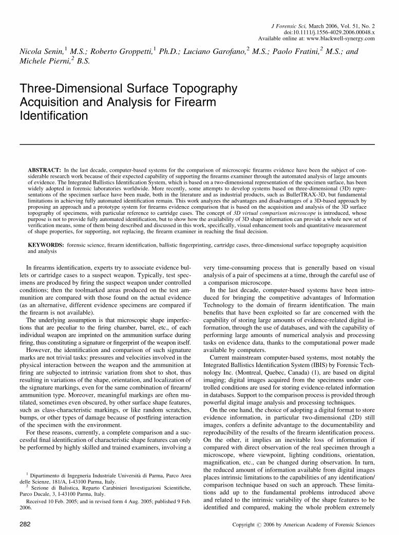
The main functional components of the general purpose systemintroduced in this work for 3D surface topography acquisition andanalysis are shown in Fig. 1, while being applied to an examplefirearm identification process based on cartridge case analysis.The same system architecture would be suitable for application tothe analysis of other surfaces in forensic applications (bullet sur-faces, toolmarks, etc.) and beyond.
In the proposed architecture, the acquisition subsystem encap-sulates the actual measurement instrument: its role consists in ac-quiring 3D surface topography information through a set ofmeasurements on the specimen surface and in providing the ac-quired 3D surface topography in a format that is compatible withthe subsequent topography analysis processes.
The analysis subsystem is a general-purpose topography anal-ysis application that is capable of performing a wide range of datamanipulation and analysis operations in order to evaluate 3D sur-face topography properties; in the specific domain of firearm
FIG. 1—Three-dimensional surface topography acquisition and analysis system architecture. Application to firearm identification based on cartridge casetopography analysis.
SENIN ET AL. . 3D SURFACE TOPOGRAPHY ACQUISITION AND ANALYSIS 283
identification through ballistic fingerprinting such a system wouldbe oriented toward performing specialized analysis tasks that maybe meaningful to the firearm identification process.
In the proposed architecture, the acquisition and analysissubsystems are purposedly kept physically separate: the archi-tecture is designed to support acquisition subsystem interchange-ability in order to overcome the measurement limitations thatare intrinsic to any specific measurement instrument that maybe embedded in the acquisition subsystem, as illustrated in thefollowing section.
The Acquisition Subsystem
The topography acquisition capabilities for the proposed archi-tecture are very much dependent on the measurement instrumentadopted: instruments may differ in resolution, range of measure-ment, acquisition technique, size of the measurable specimens,allowed specimen material, and surface properties. In the specificdomain of firearm identification, specimens generally constitute(but are not limited to) either bullets or cartridge cases. Most sur-face measurement instruments approach the surface from a pre-defined direction (e.g., from the top), and thus only have access toportions of the specimen (e.g., the above part); this may be suit-able for roughly planar surfaces, such as the base of a cartridgecase, while bullet-side surfaces and cartridge-side surfaces, beingcharacterized by round shapes, may require special solutions to beproperly acquired (typically, rotating fixtures). Cartridge base sur-faces, on the other hand, are difficult to measure for other reasons:for example, they are often characterized by large height drops(e.g., firing pin impression) and almost vertical surfaces (e.g., thegap that separates the primer from the remaining part of the base,on the surface of the cartridge case). Additional issues arise fromthe fact that both large-scale shape features (e.g., primer, firing pinimpression, ejector pin signature) and small-scale shape features(e.g., breech face marks, tiny scratches, and bumps inside the fir-ing pin impression and so forth) need to be acquired at the sametime for successful firearm identification. All the issues listedabove give rise to demanding requirements for the measurementinstrument to be adopted, in terms of resolution, range, and ca-pability of measuring hardly accessible surfaces. Such require-ments are typically difficult to fulfill at the same time and by asingle measurement instrument. The problem becomes even morecomplex because two additional requirements for the measure-ment instrument must be considered as well: the surface of thespecimen should be subjected to minimum alteration while beingmeasured, which rules out most contact-based measurement so-lutions, and topography acquisition time should be kept to theminimum, which is a fundamental issue when a large number ofspecimens need to be acquired for direct firearm identification orfor storage in a database.
All the issues listed above make the choice of a proper 3D to-pography acquisition measurement instrument a difficult task, andalso explain why digital imaging is currently the preferred choicefor 2D surface data acquisition in firearm identification. Digitalimaging is a noncontact technique, it allows for a high horizontalresolution, mostly thanks to the magnification power of light, to-gether with respectable measurement ranges, and most of the sur-face topography is acquired by a single shot (except the undercuts,of course), which leads to significant time saving. However, dig-ital imaging acquisition processes have limitations that are intrin-sic to their 2D nature, as mentioned briefly in the introduction, andas explained later in the text.
Going back to 3D surface topography, the selection of a propermeasurement solution is currently an unresolved problem. In thenext section, an example acquisition subsystem is introduced thatdoes not represent a final solution to the problems illustratedabove, but at least illustrates how some of the problems listedabove can be dealt with. Once again, it is important to point outthat the proposed architecture suggests an approach to topographydata analysis and manipulation that is independent of the meas-urement instrument, and thus, the system illustrated in the fol-lowing should be considered only as one of the many optionsavailable for acquiring topography data, and not necessarily thebest one.
A Prototype Acquisition Subsystem
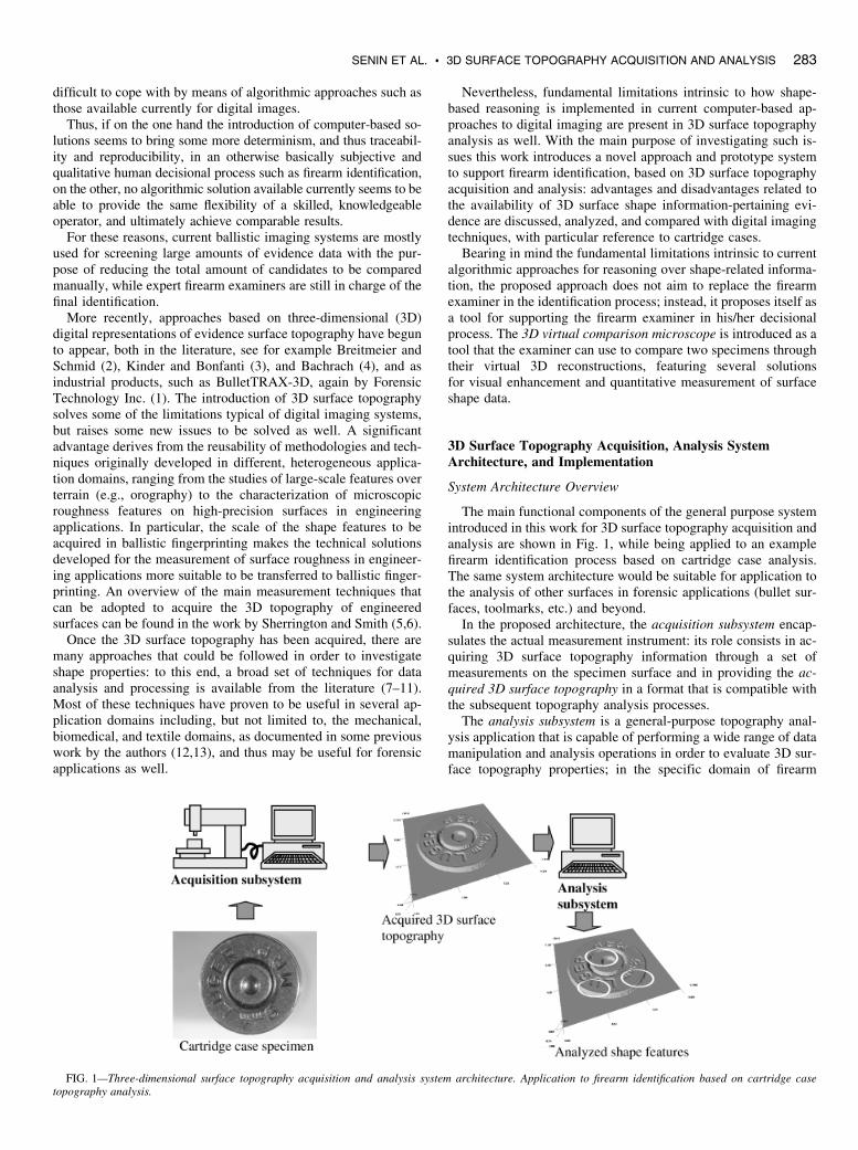
A prototype acquisition subsystem was developed at the De-partment of Industrial Engineering, University of Parma, with thecooperation of the SM s.r.l. company (Torino, Italy) (see Fig. 2).The acquisition subsystem is equipped with a commercial sensorbased on laser conoscopic holography (14) for noncontact meas-urement. The sensor is capable of measuring the distance of apoint located under the spot of the laser beam; in order to acquire acomplete 3D topography, the specimen is translated under thesensor by means of a computer-controlled x–y table, so that a se-quence of points can be acquired by scanning along the lines of arectangular grid pattern (raster scanning). The system has beendeveloped as a general-purpose surface topography measurementdevice, and it has already been applied to several surface charac-terization tasks, in various engineering domains. The current pro-totype can operate with different submicrometric verticalaccuracies, in a millimetric vertical measurement range, depend-ing on the lens assembly attached to the sensor; horizontal accu-racy, which depends on the characteristics of the x–y table, issubmicrometric as well. The system is currently capable of ac-quiring planar specimens only; however, the development of anadditional rotating fixture to allow for the measurement of roundsurfaces is in progress.
FIG. 2—Prototype three-dimensional surface topography acquisitionsystem equipped with a laser conoscopic holographic sensor and computer-controlled x–y table for precise positioning of the specimen.
284 JOURNAL OF FORENSIC SCIENCES
Formal Encoding of 3D Surface Topography
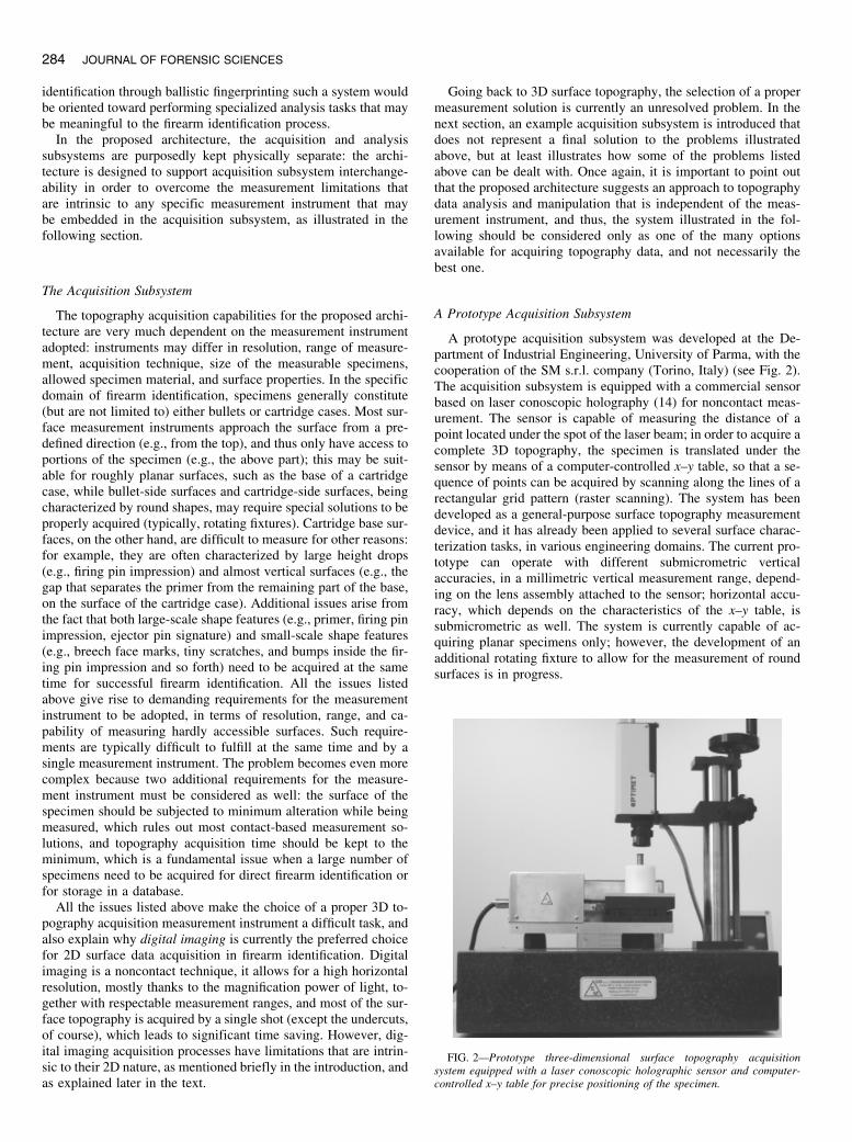
As stated previously, the main strength of the proposed archi-tecture is the capability of supporting acquisition subsystem in-terchangeability. In order to enforce this, a common format torepresent 3D surface topography data provided by the measure-ment instrument must be adopted. The proposed format is illus-trated in Fig. 3, where 3D surface topography is represented by aset of points defined by three scalar coordinates in a Cartesianreference system.
With reference to Fig. 3, surface topography data are stored as aset of Nx � Ny points arranged in an x–y grid with uniform Dx, Dy
spacing. Given this assumption, the x, y and z coordinates of theijth sample can be defined as follows:
xi ¼ Dx � i; yj ¼ Dy � j; zij ¼ z xi; yj
� �¼ z½i; j� ð1Þ
with i ¼ 0; 1; 2; . . . ;Nx � 1f g and j ¼ f0; 1; 2; . . . ;Ny � 1gUniform spacing is the strongest assumption adopted by the
proposed representation as it gives rise to an array of importantconsequences: first, surface topography data encoded as such canbe conveniently stored in a 2D matrix of z coordinates, the x and ycoordinates being retrievable by knowing matrix indices and uni-form sample spacing (see equation (1)); second, uniform x–yspacing makes the proposed representation formally equivalentto the representation of a digital image (where the RGB value ofeach pixel is stored in a cell of a 2D matrix, which can be retrievedthrough proper indices); and the formal equivalence with digitalimages opens up a wide array of possibilities for data analysis andprocessing, as will be illustrated in a later section.
The assumption of uniform x–y spacing also has some draw-backs, starting from the fact that geometric undercuts or verticalsurfaces (i.e., aligned with the z coordinate) cannot be represented,as no more than a single z value can be stored for a given pair of x–y coordinates: this may not be a serious problem in firearm iden-tification, given that most of the current measurement solutionsare not capable of detecting such cases anyway, and also giventhat most signatures on cartridge cases and bullets are either theproduct of the bullet/cartridge manufacturing process, or the prod-uct of mechanical interaction between the bullet/cartridge and
firearm parts during the firing of the firearm, or the product ofsubsequent damage of the specimen, all phenomena that are notlikely to produce such geometric entities.
The most critical issues related to uniform spacing arise whenplanning the sampling strategy, as illustrated in the next section.
Sampling Issues in Acquisition
Horizontal sampling resolution is dependent on the require-ments for the shape to be acquired. For the proposed formalism,the Nyquist criterion could be rephrased to state that sample spac-ing should be smaller than half the minimum size of the smallestshape feature to be acquired. However, as the horizontal spacingbetween samples decreases, the amount of samples needed tocover the same surface area increases, which may have repercus-sions on acquisition time span, on the memory required to storethe acquisition data and on the mathematical tractability of theacquired set of samples. As an alternative, the region to be ac-quired could be reduced in order to keep the overall number ofacquired samples constant; however, the potential loss of mean-ingfulness and representativeness of the acquired region should beconsidered as well.
The problem of identifying the proper horizontal resolution andrange for topography acquisition is fundamentally a process plan-ning problem, which should be dealt with in terms of goals (ac-quire meaningful information concerning specific relevant shapefeatures) and constraints (limitations intrinsic to the measurementsystem of choice, time requirements, memory requirements, etc.).
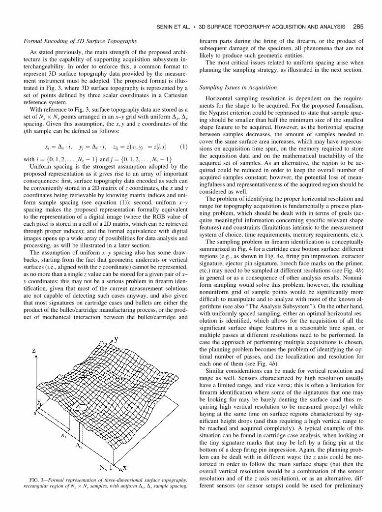
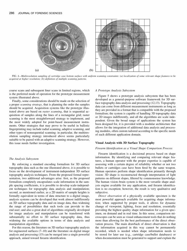
The sampling problem in firearm identification is conceptuallysummarized in Fig. 4 for a cartridge case bottom surface: differentregions (e.g., as shown in Fig. 4a, firing pin impression, extractorsignature, ejector pin signature, breech face marks on the primer,etc.) may need to be sampled at different resolutions (see Fig. 4b)in general or as a consequence of other analysis results. Nonuni-form sampling would solve this problem; however, the resultingnonuniform grid of sample points would be significantly moredifficult to manipulate and to analyze with most of the known al-gorithms (see also ‘‘The Analysis Subsystem’’). On the other hand,with uniformly spaced sampling, either an optimal horizontal res-olution is identified, which allows for the acquisition of all thesignificant surface shape features in a reasonable time span, ormultiple passes at different resolutions need to be performed. Incase the approach of performing multiple acquisitions is chosen,the planning problem becomes the problem of identifying the op-timal number of passes, and the localization and resolution foreach one of them (see Fig. 4b).
Similar considerations can be made for vertical resolution andrange as well. Sensors characterized by high resolution usuallyhave a limited range, and vice versa; this is often a limitation forfirearm identification where some of the signatures that one maybe looking for may be barely denting the surface (and thus re-quiring high vertical resolution to be measured properly) whilelaying at the same time on surface regions characterized by sig-nificant height drops (and thus requiring a high vertical range tobe reached and acquired completely). A typical example of thissituation can be found in cartridge case analysis, when looking atthe tiny signature marks that may be left by a firing pin at thebottom of a deep firing pin impression. Again, the planning prob-lem can be dealt with in different ways: the z axis could be mo-torized in order to follow the main surface shape (but then theoverall vertical resolution would be a combination of the sensorresolution and of the z axis resolution), or as an alternative, dif-ferent sensors (or sensor setups) could be used for preliminary
FIG. 3—Formal representation of three-dimensional surface topography:rectangular region of Nx � Ny samples, with uniform Dx, Dy sample spacing.
SENIN ET AL. . 3D SURFACE TOPOGRAPHY ACQUISITION AND ANALYSIS 285
coarse scans and subsequent finer scans in limited regions, whichis the preferred mode of operation for the prototype measurementsystem illustrated above.
Finally, some considerations should be made on the selection ofa proper scanning strategy, that is planning the order the samplesshould be acquired. Acquisition systems like the prototype illus-trated above are based on raster scanning, that is sequential ac-quisition of samples along the lines of a rectangular grid; rasterscanning is the most straightforward strategy to implement, andthe most widely adopted for point-based measurement instru-ments. Other strategies that may prove to be useful in ballisticfingerprinting may include radial scanning, adaptive scanning, andother types of nonsequential scanning: in particular, the multires-olution sampling strategy introduced above seems particularlysuitable to be paired with an adaptive scanning strategy. However,this issue needs further investigation.
The Analysis Subsystem
By enforcing a standard encoding formalism for 3D surfacetopography data such as the one illustrated above, it is possible tofocus on the development of instrument-independent 3D surfacetopography analysis techniques. From the proposed formal repre-sentation, two additional advantages arise: first, as the proposedformalism completely encapsulates scale information in the sam-ple spacing coefficients, it is possible to develop scale-independ-ent techniques for topography data analysis and manipulation;second, as mentioned earlier, as a 2D matrix of sample heights isformally equivalent in terms of data structure to a digital image,analysis systems can be developed that work almost indifferentlyon 3D surface topography data and on image data, thus wideningthe range of possibilities that such tools can provide to theend user; and also a great deal of algorithms originally developedfor image analysis and manipulation can be transferred withsubstantially no effort to 3D surface topography data, thuswidening the available options in terms of data analysis andmanipulation algorithms.
For this reason, the literature on 3D surface topography analysisfor engineered surfaces (7–10) and the literature on digital imageanalysis and processing (15) can be merged into a single powerfulapproach, aimed toward firearm identification.
A Prototype Analysis Subsystem
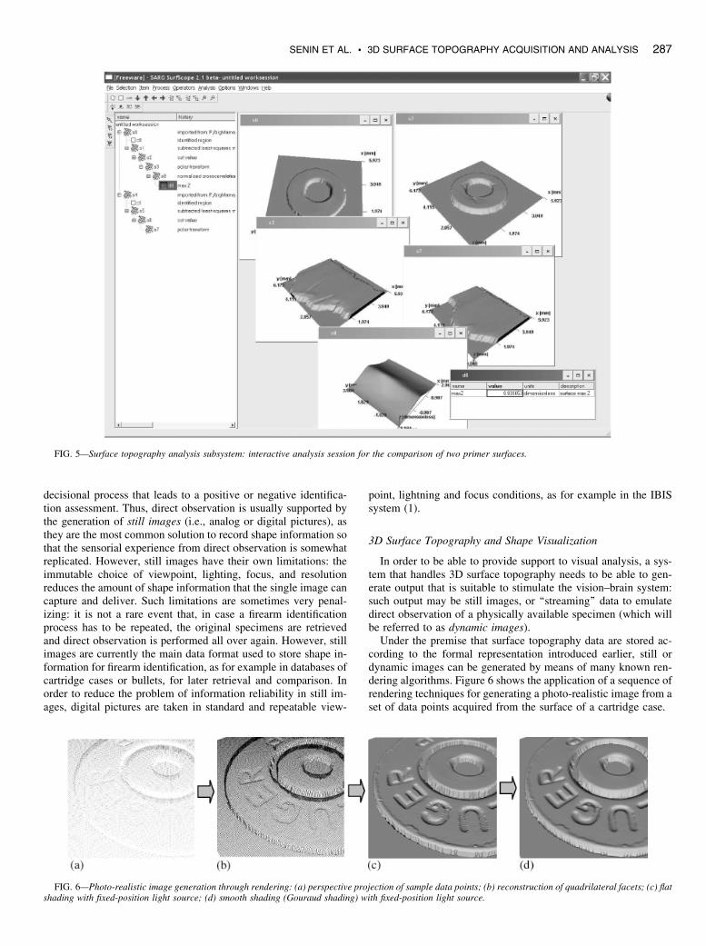
Figure 5 shows a prototype analysis subsystem that has beendeveloped as a general-purpose software framework for 3D sur-face topography data analysis and processing (12,13). Topographydata can come from different measurement instruments as long asthey are provided in a format that is compatible with the proposedformalism; the system is capable of handling 3D topography dataor 2D images indifferently, and all the algorithms are scale inde-pendent. Given the broad range of applications the system hasbeen designed for, it is provided with a modular architecture thatallows for the integration of additional data analysis and process-ing modules, often custom tailored according to the specific needsof each different application domain.
Visual Analysis with 3D Surface Topography
Firearm Identification as a Visual Shape Comparison Process
Firearm identification is a decisional process based on shapeinformation. By identifying and comparing relevant shape fea-tures, a human operator with the proper expertise is capable ofassessing with a certain degree of reliability whether or not twobullets or cartridges case have been fired by the same weapon.Human operators perform shape identification primarily throughvision: 3D shape is reconstructed through interpretation of lightpatterns on different slopes, filtered by commonsense knowledge.The human vision–brain system is the most versatile shape anal-ysis engine available for any application, and firearm identifica-tion is no exception; however, the result is very qualitative andsubjective.
Direct observation of a physically available specimen is themost powerful approach available for acquiring shape informa-tion; when supported by proper tools, it allows for dynamicchange of viewpoint, lighting, focus and resolution, essentiallyproviding the highest quality shape information for a given spec-imen, on demand and in real time. In this sense, comparison mi-croscopes can be seen as visual enhancement tools that do nothingmore than allowing for the best performance of the direct obser-vation process. The main drawback of direct observation is thatthe information acquired in this way cannot be permanentlyrecorded, which is needed when shape information needs tobe stored for later use (e.g., cartridge case/bullet databases) orwhen documentation must be generated to support and explain the
FIG. 4—Multiresolution sampling of cartridge case bottom surface with uniform scanning constraints: (a) localization of some relevant shape features to beacquired at higher resolution; (b) definition of multiple scanning patterns.
286 JOURNAL OF FORENSIC SCIENCES
decisional process that leads to a positive or negative identifica-tion assessment. Thus, direct observation is usually supported bythe generation of still images (i.e., analog or digital pictures), asthey are the most common solution to record shape information sothat the sensorial experience from direct observation is somewhatreplicated. However, still images have their own limitations: theimmutable choice of viewpoint, lighting, focus, and resolutionreduces the amount of shape information that the single image cancapture and deliver. Such limitations are sometimes very penal-izing: it is not a rare event that, in case a firearm identificationprocess has to be repeated, the original specimens are retrievedand direct observation is performed all over again. However, stillimages are currently the main data format used to store shape in-formation for firearm identification, as for example in databases ofcartridge cases or bullets, for later retrieval and comparison. Inorder to reduce the problem of information reliability in still im-ages, digital pictures are taken in standard and repeatable view-
point, lightning and focus conditions, as for example in the IBISsystem (1).
3D Surface Topography and Shape Visualization
In order to be able to provide support to visual analysis, a sys-tem that handles 3D surface topography needs to be able to gen-erate output that is suitable to stimulate the vision–brain system:such output may be still images, or ‘‘streaming’’ data to emulatedirect observation of a physically available specimen (which willbe referred to as dynamic images).
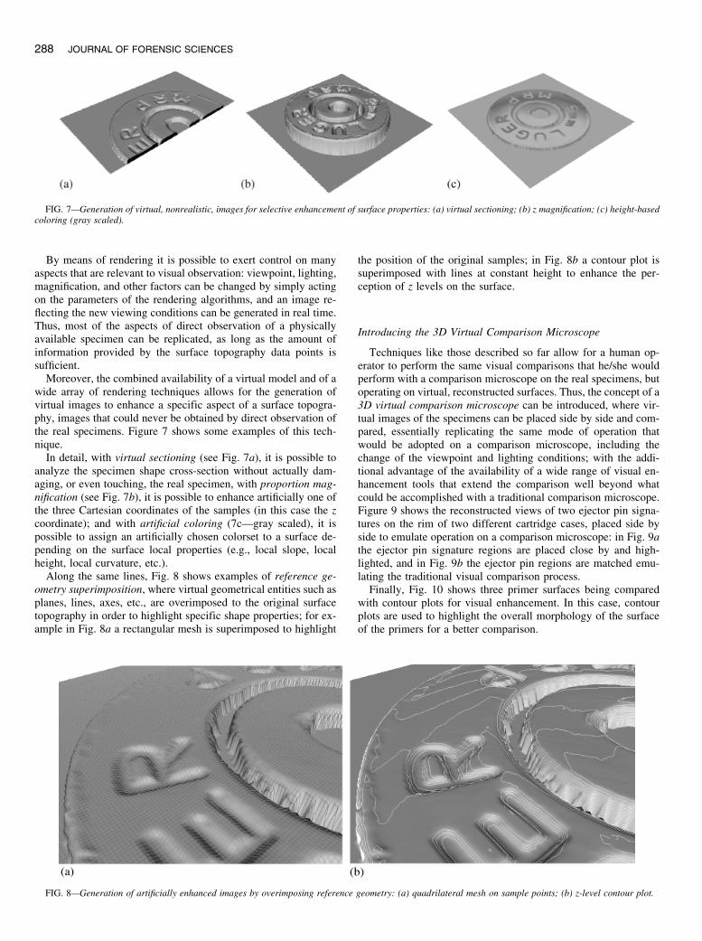
Under the premise that surface topography data are stored ac-cording to the formal representation introduced earlier, still ordynamic images can be generated by means of many known ren-dering algorithms. Figure 6 shows the application of a sequence ofrendering techniques for generating a photo-realistic image from aset of data points acquired from the surface of a cartridge case.
FIG. 5—Surface topography analysis subsystem: interactive analysis session for the comparison of two primer surfaces.
FIG. 6—Photo-realistic image generation through rendering: (a) perspective projection of sample data points; (b) reconstruction of quadrilateral facets; (c) flatshading with fixed-position light source; (d) smooth shading (Gouraud shading) with fixed-position light source.
SENIN ET AL. . 3D SURFACE TOPOGRAPHY ACQUISITION AND ANALYSIS 287
By means of rendering it is possible to exert control on manyaspects that are relevant to visual observation: viewpoint, lighting,magnification, and other factors can be changed by simply actingon the parameters of the rendering algorithms, and an image re-flecting the new viewing conditions can be generated in real time.Thus, most of the aspects of direct observation of a physicallyavailable specimen can be replicated, as long as the amount ofinformation provided by the surface topography data points issufficient.
Moreover, the combined availability of a virtual model and of awide array of rendering techniques allows for the generation ofvirtual images to enhance a specific aspect of a surface topogra-phy, images that could never be obtained by direct observation ofthe real specimens. Figure 7 shows some examples of this tech-nique.
In detail, with virtual sectioning (see Fig. 7a), it is possible toanalyze the specimen shape cross-section without actually dam-aging, or even touching, the real specimen, with proportion mag-nification (see Fig. 7b), it is possible to enhance artificially one ofthe three Cartesian coordinates of the samples (in this case the zcoordinate); and with artificial coloring (7c—gray scaled), it ispossible to assign an artificially chosen colorset to a surface de-pending on the surface local properties (e.g., local slope, localheight, local curvature, etc.).
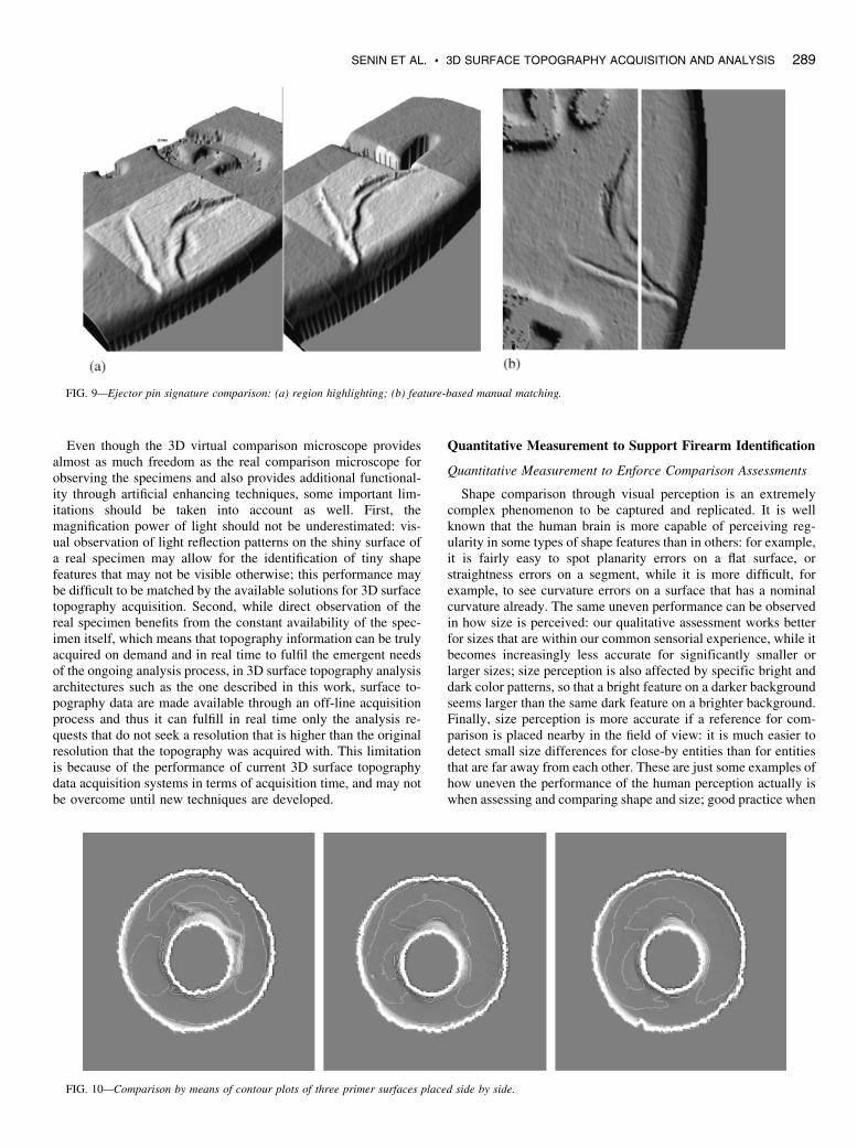
Along the same lines, Fig. 8 shows examples of reference ge-ometry superimposition, where virtual geometrical entities such asplanes, lines, axes, etc., are overimposed to the original surfacetopography in order to highlight specific shape properties; for ex-ample in Fig. 8a a rectangular mesh is superimposed to highlight
the position of the original samples; in Fig. 8b a contour plot issuperimposed with lines at constant height to enhance the per-ception of z levels on the surface.
Introducing the 3D Virtual Comparison Microscope
Techniques like those described so far allow for a human op-erator to perform the same visual comparisons that he/she wouldperform with a comparison microscope on the real specimens, butoperating on virtual, reconstructed surfaces. Thus, the concept of a3D virtual comparison microscope can be introduced, where vir-tual images of the specimens can be placed side by side and com-pared, essentially replicating the same mode of operation thatwould be adopted on a comparison microscope, including thechange of the viewpoint and lighting conditions; with the addi-tional advantage of the availability of a wide range of visual en-hancement tools that extend the comparison well beyond whatcould be accomplished with a traditional comparison microscope.Figure 9 shows the reconstructed views of two ejector pin signa-tures on the rim of two different cartridge cases, placed side byside to emulate operation on a comparison microscope: in Fig. 9athe ejector pin signature regions are placed close by and high-lighted, and in Fig. 9b the ejector pin regions are matched emu-lating the traditional visual comparison process.
Finally, Fig. 10 shows three primer surfaces being comparedwith contour plots for visual enhancement. In this case, contourplots are used to highlight the overall morphology of the surfaceof the primers for a better comparison.
FIG. 7—Generation of virtual, nonrealistic, images for selective enhancement of surface properties: (a) virtual sectioning; (b) z magnification; (c) height-basedcoloring (gray scaled).
FIG. 8—Generation of artificially enhanced images by overimposing reference geometry: (a) quadrilateral mesh on sample points; (b) z-level contour plot.
288 JOURNAL OF FORENSIC SCIENCES
Even though the 3D virtual comparison microscope providesalmost as much freedom as the real comparison microscope forobserving the specimens and also provides additional functional-ity through artificial enhancing techniques, some important lim-itations should be taken into account as well. First, themagnification power of light should not be underestimated: vis-ual observation of light reflection patterns on the shiny surface ofa real specimen may allow for the identification of tiny shapefeatures that may not be visible otherwise; this performance maybe difficult to be matched by the available solutions for 3D surfacetopography acquisition. Second, while direct observation of thereal specimen benefits from the constant availability of the spec-imen itself, which means that topography information can be trulyacquired on demand and in real time to fulfil the emergent needsof the ongoing analysis process, in 3D surface topography analysisarchitectures such as the one described in this work, surface to-pography data are made available through an off-line acquisitionprocess and thus it can fulfill in real time only the analysis re-quests that do not seek a resolution that is higher than the originalresolution that the topography was acquired with. This limitationis because of the performance of current 3D surface topographydata acquisition systems in terms of acquisition time, and may notbe overcome until new techniques are developed.
Quantitative Measurement to Support Firearm Identification
Quantitative Measurement to Enforce Comparison Assessments
Shape comparison through visual perception is an extremelycomplex phenomenon to be captured and replicated. It is wellknown that the human brain is more capable of perceiving reg-ularity in some types of shape features than in others: for example,it is fairly easy to spot planarity errors on a flat surface, orstraightness errors on a segment, while it is more difficult, forexample, to see curvature errors on a surface that has a nominalcurvature already. The same uneven performance can be observedin how size is perceived: our qualitative assessment works betterfor sizes that are within our common sensorial experience, while itbecomes increasingly less accurate for significantly smaller orlarger sizes; size perception is also affected by specific bright anddark color patterns, so that a bright feature on a darker backgroundseems larger than the same dark feature on a brighter background.Finally, size perception is more accurate if a reference for com-parison is placed nearby in the field of view: it is much easier todetect small size differences for close-by entities than for entitiesthat are far away from each other. These are just some examples ofhow uneven the performance of the human perception actually iswhen assessing and comparing shape and size; good practice when
FIG. 9—Ejector pin signature comparison: (a) region highlighting; (b) feature-based manual matching.
FIG. 10—Comparison by means of contour plots of three primer surfaces placed side by side.
SENIN ET AL. . 3D SURFACE TOPOGRAPHY ACQUISITION AND ANALYSIS 289
performing visual comparison of shapes for firearm identificationconsists in creating the conditions that maximize the performanceof the sensorial experience, which is why, for example, compar-ison microscopes are designed to place shape features side by side,in some cases even partially overlapped.
In order to compensate at least partially for the lack of uni-formity in the performance of visual perception, means for ob-taining quantitative measures of 3D surface topography shapefeatures can be introduced; measurement helps reasoning withsizes and supports shape comparison providing partial compensa-tion to the pitfalls of visual perception, adding quantitative contentto an otherwise predominantly qualitative and subjective process.
Simple Types of Measurement and Related Issues
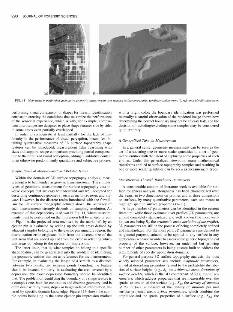
Within the domain of 3D surface topography analysis, meas-urement is to be intended as geometric measurement. The simplesttypes of geometric measurement for surface topography data in-volve concepts that are easy to understand and well accepted fordescribing continuous geometry, such as distance, area, and vol-ume. However, in the discrete realm introduced with the formal-ism for 3D surface topography defined above, the accuracy ofsuch measurements strongly depends on sampling resolution. Anexample of this dependency is shown in Fig. 11, where measure-ments must be performed on the impression left by an ejector pin:in Fig. 11a, the projected area enclosed by the marks left by anejector pin is evaluated by adding up the unit areas defined byadjacent samples belonging to the ejector pin signature region: thediscretization error originates both from the discrete size of theunit areas that are added up and from the error in selecting whichunit areas do belong to the ejector pin impression.
The latter issue, that is, what samples do belong to a specificshape feature, can be generalized into the problem of identifyingthe geometric entities that act as references for the measurement.For example, in evaluating the length of a scratch as a distancebetween two points, two extreme points bounding the featureshould be located; similarly, in evaluating the area covered by adepression, the exact depression boundary should be identifiedfirst. The problem of identifying the boundary of a shape feature isa complex one, both for continuous and discrete geometry, and isoften dealt with by using slope- or height-related information, fil-tered by specific-domain knowledge. Figure 11b shows the sam-ple points belonging to the same ejector pin impression marked
with a bright color; the boundary identification was performedmanually: a careful observation of the rendered image shows howdetermining the correct boundary may not be an easy task, and thedecision of including/excluding some samples may be consideredquite arbitrary.
A Generalized Take on Measurement
In a general sense, geometric measurement can be seen as theact of associating one or more scalar quantities to a set of geo-metric entities with the intent of capturing some properties of suchentities. Under this generalized viewpoint, many mathematicaltransforms applied to surface topography samples and resulting inone or more scalar quantities can be seen as measurement types.
Measurement Through Roughness Parameters
A considerable amount of literature work is available for sur-face roughness analysis. Roughness has been characterized overthe years, in two dimensions on profiles and in three dimensionson surfaces, by many quantitative parameters, each one meant tohighlight specific surface properties (7–11).
A large number of parameters can be identified in the currentliterature: while those evaluated over profiles (2D parameters) arealmost completely standardized and well known (the most well-known one being Ra, the arithmetic mean deviation of the profile),3D parameters are still in the process of being completely definedand standardized. For the most part, 3D parameters are defined tobe general purpose, suitable to be applied to any surface in anyapplication scenario in order to assess some generic topographicalproperty of the surface; however, an undefined but growingnumber of other parameters is being custom built to address therequirements of specific application domains.
For general-purpose 3D surface topography analysis, the mostwidely adopted parameter sets include amplitude parameters,aimed at describing properties related to the probability distribu-tion of surface heights (e.g., Sa: the arithmetic mean deviation ofsurface heights, which is the 3D counterpart of Ra); spatial pa-rameters, which address properties that are measurable over thespatial extension of the surface (e.g., Sds, the density of summitsof the surface, a measure of the density of summits per unitsurface projected area); hybrid parameters, which combine theamplitude and the spatial properties of a surface (e.g., SDq, the
FIG. 11—Main issues in performing quantitative geometric measurements over sampled surface topography: (a) discretization error; (b) reference identification error.
290 JOURNAL OF FORENSIC SCIENCES
root-mean-square slope of the surface); and functional parame-ters, which are meant to be representative of surface propertiesthat affect its functional interaction with other surfaces (e.g.,related to wear, friction, lubrication, etc.), parameters that oftenrely on the concept of bearing area, the area of a virtual cross-section that may be obtained by truncating the original surfacetopography at a given height (e.g., the parameter Sbi, surfacebearing index, the ratio of the RMS deviation over the surfaceheight at 5% bearing area).
However, such a wide choice of parameters does not necessar-ily make it easier to identify measurement types that are mean-ingful and at the same time applicable to the problem of firearmidentification. The use of roughness parameters to support firearmidentification gives rise to two main criticisms: first, parameters tobe used in surface topography comparison should have enoughdiscrimination power, meaning that they should be capable ofconveying the differences between two surfaces through their ownvalues; second, they should be able to provide measurements thatare suitable to characterize overall surface properties as well assingular, localized, surface shape features, which are often evenmore relevant in firearm identification. Unfortunately, known pa-rameters tend to perform poorly with respect to both these issues:discrimination power is generally low, as most parameters pro-duce results that summarize the properties of a surface into a sin-gle value, and thus they tend to average out local shape differencesin the process, ending up with the same parameter value even fordifferent surfaces; also, parameters tend to seldom be suitable forcharacterizing localized, singular shape features, as for the mostpart they are designed to be representative of properties involvingthe surface as a whole and lose significance on smaller entities.
In summary, the concept of using a generic mathematical trans-form on surface topography data in order to obtain a scalar quan-
tity that can be used as a measurement for surface comparisonpurposes seems promising for firearm identification through bal-listic fingerprinting. However, the application of known trans-forms, such as the parameters introduced by the literature onroughness analysis, should be performed with caution: existingparameters should be chosen, or ad hoc parameters should becreated, by looking carefully at their representational and dis-crimination power for the surface features they are meant to beapplied to.
Data Preprocessing for Measurement
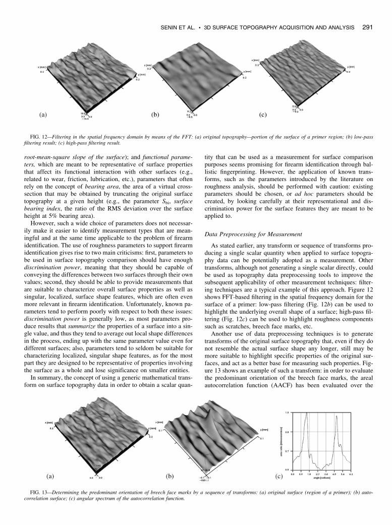
As stated earlier, any transform or sequence of transforms pro-ducing a single scalar quantity when applied to surface topogra-phy data can be potentially adopted as a measurement. Othertransforms, although not generating a single scalar directly, couldbe used as topography data preprocessing tools to improve thesubsequent applicability of other measurement techniques: filter-ing techniques are a typical example of this approach. Figure 12shows FFT-based filtering in the spatial frequency domain for thesurface of a primer: low-pass filtering (Fig. 12b) can be used tohighlight the underlying overall shape of a surface; high-pass fil-tering (Fig. 12c) can be used to highlight roughness componentssuch as scratches, breech face marks, etc.
Another use of data preprocessing techniques is to generatetransforms of the original surface topography that, even if they donot resemble the actual surface shape any longer, still may bemore suitable to highlight specific properties of the original sur-faces, and act as a better base for measuring such properties. Fig-ure 13 shows an example of such a transform: in order to evaluatethe predominant orientation of the breech face marks, the arealautocorrelation function (AACF) has been evaluated over the
FIG. 12—Filtering in the spatial frequency domain by means of the FFT: (a) original topography—portion of the surface of a primer region; (b) low-passfiltering result; (c) high-pass filtering result.
FIG. 13—Determining the predominant orientation of breech face marks by a sequence of transforms: (a) original surface (region of a primer); (b) auto-correlation surface; (c) angular spectrum of the autocorrelation function.
SENIN ET AL. . 3D SURFACE TOPOGRAPHY ACQUISITION AND ANALYSIS 291
original surface topography of the primer, and the angular spec-trum of the AACF has been computed, its maximum values cor-responding to the predominant orientation of the surface texture.
Cross-Correlation as a Similarity Metric
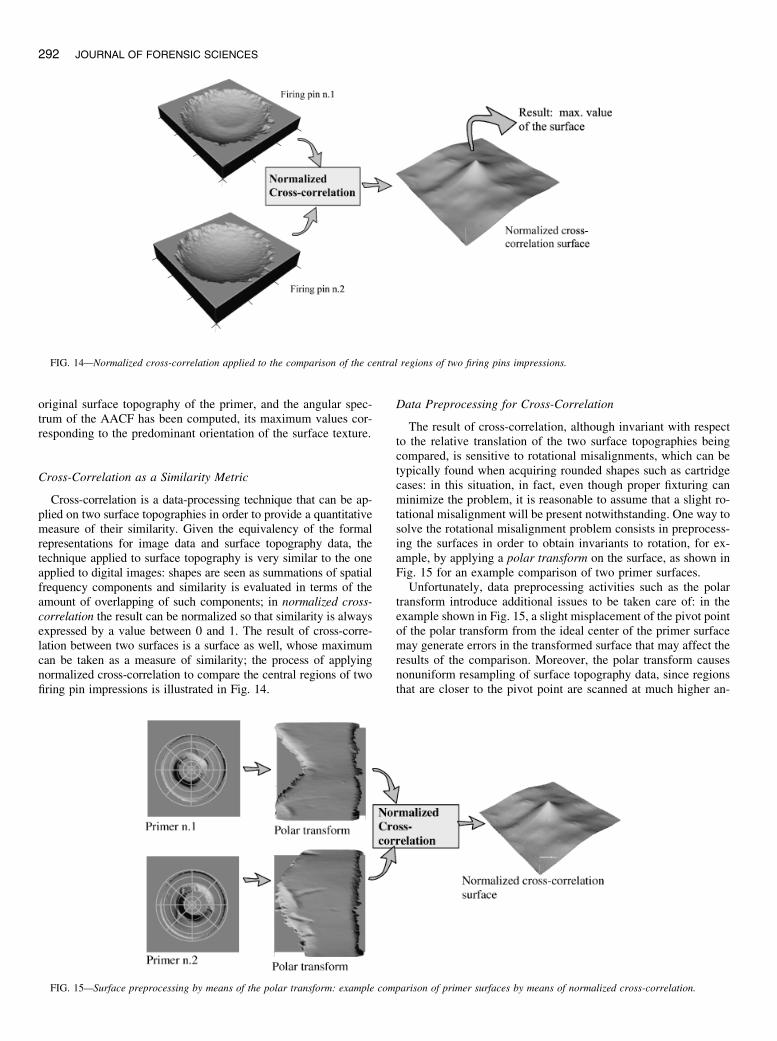
Cross-correlation is a data-processing technique that can be ap-plied on two surface topographies in order to provide a quantitativemeasure of their similarity. Given the equivalency of the formalrepresentations for image data and surface topography data, thetechnique applied to surface topography is very similar to the oneapplied to digital images: shapes are seen as summations of spatialfrequency components and similarity is evaluated in terms of theamount of overlapping of such components; in normalized cross-correlation the result can be normalized so that similarity is alwaysexpressed by a value between 0 and 1. The result of cross-corre-lation between two surfaces is a surface as well, whose maximumcan be taken as a measure of similarity; the process of applyingnormalized cross-correlation to compare the central regions of twofiring pin impressions is illustrated in Fig. 14.
Data Preprocessing for Cross-Correlation
The result of cross-correlation, although invariant with respectto the relative translation of the two surface topographies beingcompared, is sensitive to rotational misalignments, which can betypically found when acquiring rounded shapes such as cartridgecases: in this situation, in fact, even though proper fixturing canminimize the problem, it is reasonable to assume that a slight ro-tational misalignment will be present notwithstanding. One way tosolve the rotational misalignment problem consists in preprocess-ing the surfaces in order to obtain invariants to rotation, for ex-ample, by applying a polar transform on the surface, as shown inFig. 15 for an example comparison of two primer surfaces.
Unfortunately, data preprocessing activities such as the polartransform introduce additional issues to be taken care of: in theexample shown in Fig. 15, a slight misplacement of the pivot pointof the polar transform from the ideal center of the primer surfacemay generate errors in the transformed surface that may affect theresults of the comparison. Moreover, the polar transform causesnonuniform resampling of surface topography data, since regionsthat are closer to the pivot point are scanned at much higher an-
FIG. 14—Normalized cross-correlation applied to the comparison of the central regions of two firing pins impressions.
FIG. 15—Surface preprocessing by means of the polar transform: example comparison of primer surfaces by means of normalized cross-correlation.
292 JOURNAL OF FORENSIC SCIENCES
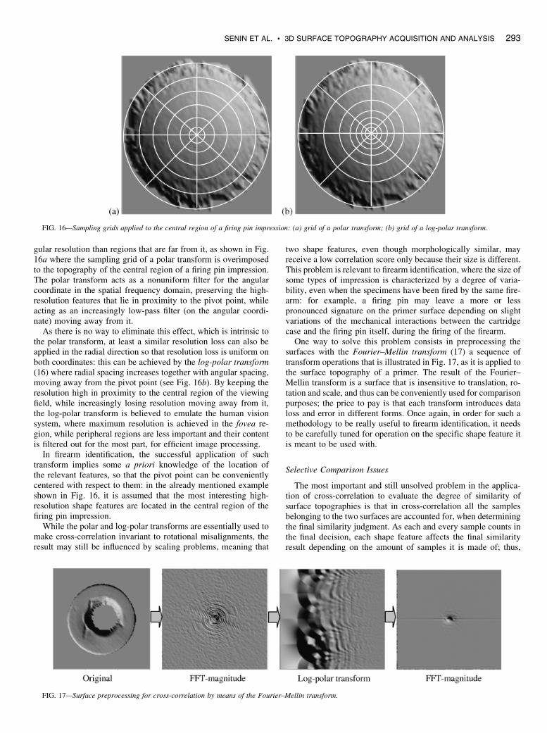
gular resolution than regions that are far from it, as shown in Fig.16a where the sampling grid of a polar transform is overimposedto the topography of the central region of a firing pin impression.The polar transform acts as a nonuniform filter for the angularcoordinate in the spatial frequency domain, preserving the high-resolution features that lie in proximity to the pivot point, whileacting as an increasingly low-pass filter (on the angular coordi-nate) moving away from it.
As there is no way to eliminate this effect, which is intrinsic tothe polar transform, at least a similar resolution loss can also beapplied in the radial direction so that resolution loss is uniform onboth coordinates: this can be achieved by the log-polar transform(16) where radial spacing increases together with angular spacing,moving away from the pivot point (see Fig. 16b). By keeping theresolution high in proximity to the central region of the viewingfield, while increasingly losing resolution moving away from it,the log-polar transform is believed to emulate the human visionsystem, where maximum resolution is achieved in the fovea re-gion, while peripheral regions are less important and their contentis filtered out for the most part, for efficient image processing.
In firearm identification, the successful application of suchtransform implies some a priori knowledge of the location ofthe relevant features, so that the pivot point can be convenientlycentered with respect to them: in the already mentioned exampleshown in Fig. 16, it is assumed that the most interesting high-resolution shape features are located in the central region of thefiring pin impression.
While the polar and log-polar transforms are essentially used tomake cross-correlation invariant to rotational misalignments, theresult may still be influenced by scaling problems, meaning that
two shape features, even though morphologically similar, mayreceive a low correlation score only because their size is different.This problem is relevant to firearm identification, where the size ofsome types of impression is characterized by a degree of varia-bility, even when the specimens have been fired by the same fire-arm: for example, a firing pin may leave a more or lesspronounced signature on the primer surface depending on slightvariations of the mechanical interactions between the cartridgecase and the firing pin itself, during the firing of the firearm.
One way to solve this problem consists in preprocessing thesurfaces with the Fourier–Mellin transform (17) a sequence oftransform operations that is illustrated in Fig. 17, as it is applied tothe surface topography of a primer. The result of the Fourier–Mellin transform is a surface that is insensitive to translation, ro-tation and scale, and thus can be conveniently used for comparisonpurposes; the price to pay is that each transform introduces dataloss and error in different forms. Once again, in order for such amethodology to be really useful to firearm identification, it needsto be carefully tuned for operation on the specific shape feature itis meant to be used with.
Selective Comparison Issues
The most important and still unsolved problem in the applica-tion of cross-correlation to evaluate the degree of similarity ofsurface topographies is that in cross-correlation all the samplesbelonging to the two surfaces are accounted for, when determiningthe final similarity judgment. As each and every sample counts inthe final decision, each shape feature affects the final similarityresult depending on the amount of samples it is made of; thus,
FIG. 16—Sampling grids applied to the central region of a firing pin impression: (a) grid of a polar transform; (b) grid of a log-polar transform.
FIG. 17—Surface preprocessing for cross-correlation by means of the Fourier–Mellin transform.
SENIN ET AL. . 3D SURFACE TOPOGRAPHY ACQUISITION AND ANALYSIS 293
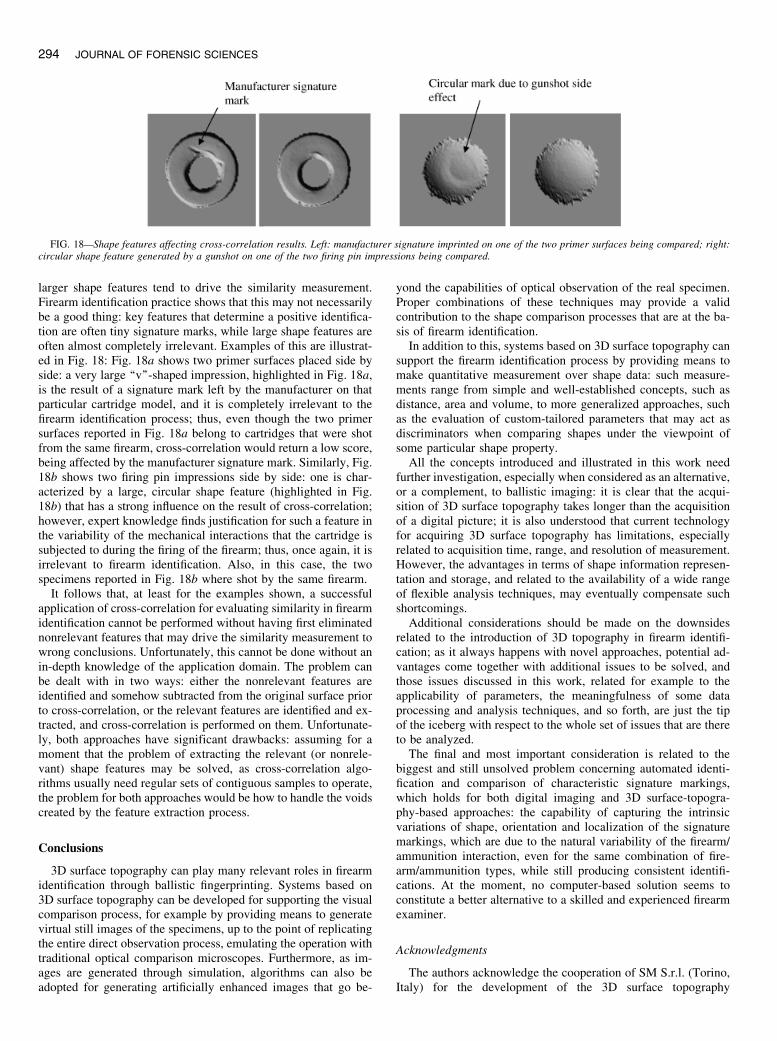
larger shape features tend to drive the similarity measurement.Firearm identification practice shows that this may not necessarilybe a good thing: key features that determine a positive identifica-tion are often tiny signature marks, while large shape features areoften almost completely irrelevant. Examples of this are illustrat-ed in Fig. 18: Fig. 18a shows two primer surfaces placed side byside: a very large ‘‘v’’-shaped impression, highlighted in Fig. 18a,is the result of a signature mark left by the manufacturer on thatparticular cartridge model, and it is completely irrelevant to thefirearm identification process; thus, even though the two primersurfaces reported in Fig. 18a belong to cartridges that were shotfrom the same firearm, cross-correlation would return a low score,being affected by the manufacturer signature mark. Similarly, Fig.18b shows two firing pin impressions side by side: one is char-acterized by a large, circular shape feature (highlighted in Fig.18b) that has a strong influence on the result of cross-correlation;however, expert knowledge finds justification for such a feature inthe variability of the mechanical interactions that the cartridge issubjected to during the firing of the firearm; thus, once again, it isirrelevant to firearm identification. Also, in this case, the twospecimens reported in Fig. 18b where shot by the same firearm.
It follows that, at least for the examples shown, a successfulapplication of cross-correlation for evaluating similarity in firearmidentification cannot be performed without having first eliminatednonrelevant features that may drive the similarity measurement towrong conclusions. Unfortunately, this cannot be done without anin-depth knowledge of the application domain. The problem canbe dealt with in two ways: either the nonrelevant features areidentified and somehow subtracted from the original surface priorto cross-correlation, or the relevant features are identified and ex-tracted, and cross-correlation is performed on them. Unfortunate-ly, both approaches have significant drawbacks: assuming for amoment that the problem of extracting the relevant (or nonrele-vant) shape features may be solved, as cross-correlation algo-rithms usually need regular sets of contiguous samples to operate,the problem for both approaches would be how to handle the voidscreated by the feature extraction process.
Conclusions
3D surface topography can play many relevant roles in firearmidentification through ballistic fingerprinting. Systems based on3D surface topography can be developed for supporting the visualcomparison process, for example by providing means to generatevirtual still images of the specimens, up to the point of replicatingthe entire direct observation process, emulating the operation withtraditional optical comparison microscopes. Furthermore, as im-ages are generated through simulation, algorithms can also beadopted for generating artificially enhanced images that go be-
yond the capabilities of optical observation of the real specimen.Proper combinations of these techniques may provide a validcontribution to the shape comparison processes that are at the ba-sis of firearm identification.
In addition to this, systems based on 3D surface topography cansupport the firearm identification process by providing means tomake quantitative measurement over shape data: such measure-ments range from simple and well-established concepts, such asdistance, area and volume, to more generalized approaches, suchas the evaluation of custom-tailored parameters that may act asdiscriminators when comparing shapes under the viewpoint ofsome particular shape property.
All the concepts introduced and illustrated in this work needfurther investigation, especially when considered as an alternative,or a complement, to ballistic imaging: it is clear that the acqui-sition of 3D surface topography takes longer than the acquisitionof a digital picture; it is also understood that current technologyfor acquiring 3D surface topography has limitations, especiallyrelated to acquisition time, range, and resolution of measurement.However, the advantages in terms of shape information represen-tation and storage, and related to the availability of a wide rangeof flexible analysis techniques, may eventually compensate suchshortcomings.
Additional considerations should be made on the downsidesrelated to the introduction of 3D topography in firearm identifi-cation; as it always happens with novel approaches, potential ad-vantages come together with additional issues to be solved, andthose issues discussed in this work, related for example to theapplicability of parameters, the meaningfulness of some dataprocessing and analysis techniques, and so forth, are just the tipof the iceberg with respect to the whole set of issues that are thereto be analyzed.
The final and most important consideration is related to thebiggest and still unsolved problem concerning automated identi-fication and comparison of characteristic signature markings,which holds for both digital imaging and 3D surface-topogra-phy-based approaches: the capability of capturing the intrinsicvariations of shape, orientation and localization of the signaturemarkings, which are due to the natural variability of the firearm/ammunition interaction, even for the same combination of fire-arm/ammunition types, while still producing consistent identifi-cations. At the moment, no computer-based solution seems toconstitute a better alternative to a skilled and experienced firearmexaminer.
Acknowledgments
The authors acknowledge the cooperation of SM S.r.l. (Torino,Italy) for the development of the 3D surface topography
FIG. 18—Shape features affecting cross-correlation results. Left: manufacturer signature imprinted on one of the two primer surfaces being compared; right:circular shape feature generated by a gunshot on one of the two firing pin impressions being compared.
294 JOURNAL OF FORENSIC SCIENCES

acquisition subsystem and the support of Pertel S.r.l. and OptimetOptical Metrology Ltd. (Jerusalem, Israel) for the integration ofthe laser sensor into the acquisition subsystem.
References
1. http://www.fti-ibis.com2. Breitmeier U, Schmid H. Lasercomp: a surface measurement system for
forensic applications. Forensic Sci Int 1997;89:1–13.3. Kinder JD, Bonfanti M. Automated comparisons of bullet striations based
on 3D topography. Forensic Sci Int 1999;101:85–93.4. Bachrach B. Development of a 3D-based automated firearms evidence
comparison system. J Forensic Sci 2002;47(6):1–12.5. Sherrington I, Smith EH. Modern measurement techniques in surface me-
trology: part I; stylus instruments, electron microscopy and non-opticalcomparators. Wear 1998;125(3):271–88.
6. Sherrington I, Smith EH. Modern measurement techniques in surface me-trology: part II; optical instruments. Wear 1998;125(3):289–308.
7. Dong WP, Sullivan PJ, Stout KJ. Comprehensive study of parameters forcharacterising 3D surface topography I: some inherent properties of pa-rameter variation. Wear 1992;167:9–21.
8. Dong WP, Sullivan PJ, Stout KJ. Comprehensive study of parameters forcharacterising 3D surface topography II: statistical properties of parametervariation. Wear 1993;167:9–21.
9. Dong WP, Sullivan PJ, Stout KJ. Comprehensive study of parameters forcharacterising 3D surface topography III: parameters for characterisingamplitude and some functional properties. Wear 1994;178:29–43.
10. Dong WP, Sullivan PJ, Stout KJ. Comprehensive study of parameters forcharacterising 3D surface topography IV: parameters for characterisingspatial and hybrid properties. Wear 1994;178:45–60.
11. Lonardo PM, Trumpold H, De Chiffre L. Progress in 3D surface micro-topography characterization. CIRP Ann 1996;45(2):589–98.
12. Groppetti R, Senin N. Bioceramic materials surface topography measure-ment and analysis for biomedical applications. In: Ravaglioli A, KrajewskiA, editors. Ceramics cells and tissues. Bioceramic surfaces. Behaviourin vitro and in vivo. Proceedings of the 8th Meeting and Seminar. March18–21, 2003, Faenza, Italy. Forli/Italy: Consiglio Nazionale delle Ricerche(CNR); 2003:16–23.
13. Groppetti R, Senin N. A contribution to the development of three-dimen-sional nano and micro-topography measurement and analysis techniquesand systems. 11th International Metrology Congress, Oct 20–23, 2003,Toulon, France. Montpellier Cedex 3/France: College Francais de Metro-logie; 2003:54–61.
14. Sirat G, Paz F. Conoscopic probes are set to transform industrial metrol-ogy. Sensor Rev 1998;18(2):108–10.
15. Pratt WK. Digital image processing: PIKS inside. 3rd ed. New York: JohnWiley & Sons Inc.; 2001.
16. PetersII RA, Bishay M, Rogers T. On the computation of the log-polartransform. Nashville (TN): Vanderbilt University, School of Engine-ering, Center for Intelligent Systems, Intelligent Robotics Laboratory,1996.
17. Casasent D, Psaltis D. Position, rotation, and scale invariant optical cor-relation. Appl Opt 1976;15(7):1795–9.
Additional information and reprint requests:Nicola Senin, M.S.ProfessorDipartimento di Ingegneria IndustrialeUniversita di ParmaParco Area delle Scienze 181/AI-43100 Parma (PR)ItalyE-mail: [email protected]
SENIN ET AL. . 3D SURFACE TOPOGRAPHY ACQUISITION AND ANALYSIS 295