three phase bldc motor driver mini drive 100 1e user manualthree phase bldc motor driver mini drive...
TRANSCRIPT
Three Phase BLDC Motor DriverMini Drive 100 1E User Manual
Vita Technology Pvt. Ltd.3/1, Annaiah Road, Yelachenahalli
off 10th km, Kanakapura Road, J. P. Nagar PostBangalore - 560 078, India
Web: http://www.vitatechindia.com
April, 2010. r1
Contents
Contents i
List of Figures ii
List of Tables iii
1 Introduction 1
2 Identification of Components 2
i

Vita Technology, Bangalore ii
2.1 List of Items Included in the Kit . . . . . . . . 3
3 Maximum Limits and Typical Rating 3
4 Controller Dimensions 5
5 Connections 65.1 Supply Voltage Connections . . . . . . . . . . 75.2 Hall Effect Sensor Connections . . . . . . . . . 75.3 Motor Phase Connections . . . . . . . . . . . . 7
6 Operation 96.1 Tuning the PI Controller Gains . . . . . . . . . 106.2 Adjusting the Motor Speed . . . . . . . . . . . 11
7 Features and Caution 11
8 Warranty 12
Index 14
List of Figures1 Top view of the board . . . . . . . . . . . . . . 12 Identification of components on the drive . . . 23 Controller dimensions (x, y) . . . . . . . . . . 54 Controller dimensions (z) . . . . . . . . . . . . 65 Mini drive running a fan load . . . . . . . . . . 9
April 2010 Mini Drive 100 1E User Manual
Vita Technology, Bangalore iii
List of Tables1 Components of the board . . . . . . . . . . . . 32 Items included in the kit . . . . . . . . . . . . 43 Drive rating . . . . . . . . . . . . . . . . . . . 44 Hall sensor connector color code . . . . . . . . 85 Motor phase connections . . . . . . . . . . . . 86 Motor and Hall sensor phasing . . . . . . . . . 8
April 2010 Mini Drive 100 1E User Manual
Vita Technology, Bangalore 1
1 Introduction
Thank you for using our product. It is highly recommendedthat you go through this user manual to understand the safetylimits and rating limits so as to not damage the motor ordrive. The drive may be permanently damaged if used im-properly.
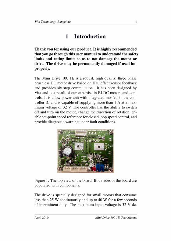
The Mini Drive 100 1E is a robust, high quality, three phasebrushless DC motor drive based on Hall effect sensor feedbackand provides six-step commutation. It has been designed byVita and is a result of our expertise in BLDC motors and con-trols. It is a low power unit with integrated mosfets in the con-troller IC and is capable of supplying more than 1 A at a max-imum voltage of 32 V. The controller has the ability to switchoff and turn on the motor, change the direction of rotation, en-able set-point speed reference for closed loop speed control, andprovide diagnostic warning under fault conditions.
Figure 1: The top view of the board. Both sides of the board arepopulated with components.
The drive is specially designed for small motors that consumeless than 25 W continuously and up to 40 W for a few secondsof intermittent duty. The maximum input voltage is 32 V dc.
April 2010 Mini Drive 100 1E User Manual

Vita Technology, Bangalore 2
It is suitable for small brushless DC motors that drive pumps,fans, and other such applications.
Customized versions of the drive with additional controls canbe provided by Vita if required.
2 Identification of Components
Fig. 2 shows the list of components of the drive. Later sec-tions describe in detail the method of connecting the motor andvarious other parts to the controller PCB.
Figure 2: Identification of the components on the board of thedrive. Please refer to table 1 for the complete listing.
April 2010 Mini Drive 100 1E User Manual

Vita Technology, Bangalore 3
Table 1: List of important components located on the PCB.
Item number Description1 Supply voltage connector (Note polarity on)
PCB when connecting.)2 ON/OFF switch header (3 pin)3 Forward/Reverse switch header (3 pin)4 Speed control potentiometer header (3 pin)5 ON/OFF LED (green)6 Forward/Reverse LED (blue)7 FAULT LED (red)8 Integrator gain control (Pot)9 Multiplier gain control (Pot)
10 Hall effect sensor header (5 pin)11 Motor phase connectors
2.1 List of Items Included in the Kit
Table 2 lists the items provided in the kit. Please make sure youhave all the components before attempting to mate the motorand controller board.
3 Maximum Limits and Typical Rating
Table 3 shows the maximum and typical values of the drive con-troller. Please note that the maximum current is only for inter-mittent duty and the drive should not be driven for more than afew seconds at the extreme end of the current value. The on-resistance of the power devices inside the IC will produce highheat loss which combined with the switching losses may per-
April 2010 Mini Drive 100 1E User Manual

Vita Technology, Bangalore 4
Table 2: List of items included in the standard Mini Drive Kit
# Item Quantity Description1 Mini drive PCB 1 Motor controller board with heat sink
mounted on top side.2 User manual 1 This manual may be downloaded if
not availabe with the kit.3 Switch interface 2 For the ON/OFF and F/R switches.
300 mm length 3 wire cable withswitch on one side and maleconnector on the other end.
4 Potentiometer 1 10 k, 10 turn pot on one end of 3 wireinterface cable with male connector at the
other end (300 mm length).5 Hall sensor 1 600 mm, 5 wire cable with 5 pin
interface female connector at one end.6 Mounting nuts 4 Nuts to lock the mounting screws.
manently damage the control board.
Table 3: Rating of the drive, typical and maximum values.
Description Min Max Typ UnitsSupply voltage, Vs 8 32 12-24 V dcSupply current, Is 10 m 2.0 < 1 A dcAmbient temperature, Top 5 45 25 oCSpeed with 8 pole motor - 30k - rpm
Please ensure that the typical current rating is not crossed andthe maximum voltage and temperature ratings are honored at all
April 2010 Mini Drive 100 1E User Manual

Vita Technology, Bangalore 5
times. Load currents greater than 1 A can be obtained if there isno chopping. Please ensure that the motor rated torque andrated speed can be fully obtained at rated voltage withoutPWM for current regulation. This way the full power spec-trum of the IC can be used. If the motor used is of a higher volt-age and speed rating, the duty cycle reduction of the PWM maycause severe overheating of the IC which will result in severedegradation of the available output power. The typical inputpower for continuous operation is 25 W.
4 Controller Dimensions
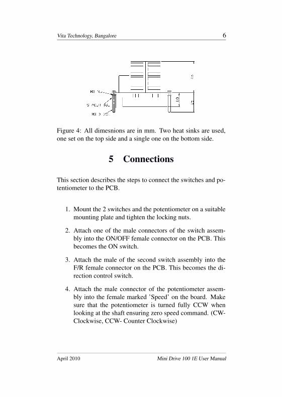
The board size is approximately 77 x 57 mm, it is about the sizeof a business or credit card. Fig. 3 and 4 show the top view andside view of the board.
Figure 3: All dimensions are in mm
April 2010 Mini Drive 100 1E User Manual
Vita Technology, Bangalore 6
Figure 4: All dimesnions are in mm. Two heat sinks are used,one set on the top side and a single one on the bottom side.
5 Connections
This section describes the steps to connect the switches and po-tentiometer to the PCB.
1. Mount the 2 switches and the potentiometer on a suitablemounting plate and tighten the locking nuts.
2. Attach one of the male connectors of the switch assem-bly into the ON/OFF female connector on the PCB. Thisbecomes the ON switch.
3. Attach the male of the second switch assembly into theF/R female connector on the PCB. This becomes the di-rection control switch.
4. Attach the male connector of the potentiometer assem-bly into the female marked ’Speed’ on the board. Makesure that the potentiometer is turned fully CCW whenlooking at the shaft ensuring zero speed command. (CW-Clockwise, CCW- Counter Clockwise)
April 2010 Mini Drive 100 1E User Manual

Vita Technology, Bangalore 7
The above instructions take care of switching the drive on andoff, changing directions, and adjustable speed control.
5.1 Supply Voltage Connections
Connect two wires with appropriate color coding and cross sec-tional area (these two wires are not supplied as part of the kit)to the supply voltage connector. Make sure that the polarity ofthe positive and return lines match with the drive.
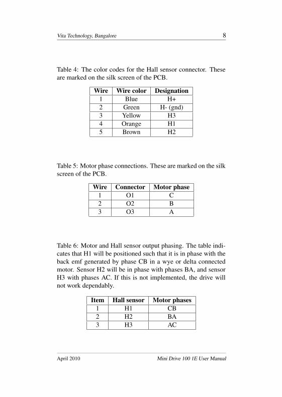
5.2 Hall Effect Sensor Connections
Table 4 shows the color code for the Hall sensor connector withthe 600 mm cable assembly. Please ensure that the colors anddescription in the table is followed when soldering the wire endsto the Hall sensors. The control board contains the requiredpull-up resistors. The Hall sensor spacing should be 120 elec-trical degrees. This controller cannot work with 60 electricaldegree spaced Hall sensors. The controller has been verified us-ing bi-polar Hall sensors with internal Schmidt trigger. Pleasedo not use analog Hall sensors as the controller will not work.A dedicated regulator on the PCB supplies 5 V dc to the Halleffect sensors.
5.3 Motor Phase Connections
Table 5 shows the sequence of connecting the three phases ofthe motor to the control board. For proper operation of themotor-controller combination, the back emf generated by thephases must be in phase with the Hall effect sensor outputs. Seetable 6.
April 2010 Mini Drive 100 1E User Manual
Vita Technology, Bangalore 8
Table 4: The color codes for the Hall sensor connector. Theseare marked on the silk screen of the PCB.
Wire Wire color Designation1 Blue H+2 Green H- (gnd)3 Yellow H34 Orange H15 Brown H2
Table 5: Motor phase connections. These are marked on the silkscreen of the PCB.
Wire Connector Motor phase1 O1 C2 O2 B3 O3 A
Table 6: Motor and Hall sensor output phasing. The table indi-cates that H1 will be positioned such that it is in phase with theback emf generated by phase CB in a wye or delta connectedmotor. Sensor H2 will be in phase with phases BA, and sensorH3 with phases AC. If this is not implemented, the drive willnot work dependably.
Item Hall sensor Motor phases1 H1 CB2 H2 BA3 H3 AC
April 2010 Mini Drive 100 1E User Manual

Vita Technology, Bangalore 9
6 Operation
The motor is operated after the power supply connection hasbeen made and the supply voltage is turned on. Even when themotor is not operating and supply is available, the drive is insleep mode. It is turned on when the on/off switch is movedto ON position. If the motor does not rotate, slowly move thespeed potentiometer knob CW to increase the speed command.The motor will start to rotate and increase its speed. When thepotentiometer has turned CW fully, the motor should be runningat its maximum speed with no PWM to control speed. If themotor runs and it appears to be not fully controllable, it meansthat the drive-motor combination needs tunings.
Figure 5: The image shows the drive running a small fan load.The speed can be controlled by using the potentiometer, theswitch on the left is to turn on or off the motor, the switch onthe right is to change the direction of rotation. The Hall sensorsinside the motor are fed to the controller using the supplied 5pin cable with the 5 pin male attached to one end (item 5 in kit).
April 2010 Mini Drive 100 1E User Manual
Vita Technology, Bangalore 10
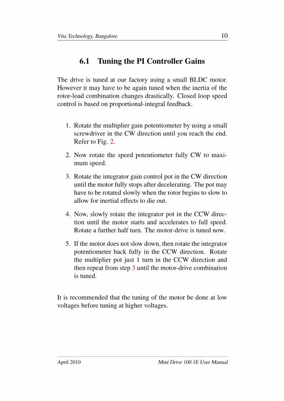
6.1 Tuning the PI Controller Gains
The drive is tuned at our factory using a small BLDC motor.However it may have to be again tuned when the inertia of therotor-load combination changes drastically. Closed loop speedcontrol is based on proportional-integral feedback.
1. Rotate the multiplier gain potentiometer by using a smallscrewdriver in the CW direction until you reach the end.Refer to Fig. 2.
2. Now rotate the speed potentiometer fully CW to maxi-mum speed.
3. Rotate the integrator gain control pot in the CW directionuntil the motor fully stops after decelerating. The pot mayhave to be rotated slowly when the rotor begins to slow toallow for inertial effects to die out.
4. Now, slowly rotate the integrator pot in the CCW direc-tion until the motor starts and accelerates to full speed.Rotate a further half turn. The motor-drive is tuned now.
5. If the motor does not slow down, then rotate the integratorpotentiometer back fully in the CCW direction. Rotatethe multiplier pot just 1 turn in the CCW direction andthen repeat from step 3 until the motor-drive combinationis tuned.
It is recommended that the tuning of the motor be done at lowvoltages before tuning at higher voltages.
April 2010 Mini Drive 100 1E User Manual

Vita Technology, Bangalore 11
6.2 Adjusting the Motor Speed
If required, the tuning described in the previous section has to beperformed. After which, the speed potentiometer can be rotatedback in the CCW direction to reduce the speed. When it is ro-tated fully in the CCW direction, the motor should stop. When itis rotated fully in the the CW direction, the motor should reachmaximum speed. At any midway point, say 50% speed, if thesupply voltage is reduced, it should be seen that the motor staysat almost the same speed up to a lower point after which thespeed control is lost. On the higher side, the controller shouldmaintain the same speed all the way up to 32 V dc.
7 Features and Caution
The drive is protected against reverse voltage polarity via a se-ries diode. It is also protected against voltage transients by usinga parallel zener diode.
The fault indicator (red LED) will light up when:
• The internal temperature of the IC is excessive
• An over-current situation has occurred
When the fault indicator lights up, the power switches of thethree phase bridge of the controller are automatically disabled.If the fault indicator lights up, the drive must be switched offimmediately and the temperature of the IC checked.
Important: Never change the direction of rotation when themotor is already running in any one direction. The followinginstructions must be followed to prevent permanent drive failure
April 2010 Mini Drive 100 1E User Manual
Vita Technology, Bangalore 12
due to over-current conditions that exist in dynamic directionreversals of the motor:
1. Switch off motor by using the ON/OFF switch
2. Wait for the rotor or load to completely stop rotating
3. Change the direction with F/R switch
4. Switch on the motor now using the ON/OFF switch
The blue LED indicates operation in one direction, it is not litwhile operating in the reverse direction.
The drive is not coated with any protective coating after assem-bly. Please ensure that no moisture, liquid, or any conductingfluid or components come in contact with the PCB. Periodicallyplease clean the board with low pressure compressed air to re-move dirt and dust that may cause faults and perhaps permanentdrive failure.
8 Warranty
No modification of any sort of the PCB is permitted withoutwritten authorization from Vita.
Each unit is completely tested at our factory after assembly ofthe PCB with a brushless DC motor and data recorded with theserial number. The switches and potentiometer that are includedin the kit are used during testing. No defective components willbe shipped out. As the drive can be damaged if not used withcaution and if used outside the envelope that it has been de-signed to operate in, and the cause cannot be verified after fail-
April 2010 Mini Drive 100 1E User Manual
Vita Technology, Bangalore 13
ure, there is no warranty for the drive implied or supplied. In nocase will a free replacement PCB be provided.
Vita reserves the right to change this specification with suitable modi-fications at anytime. c© Vita Technology, Pvt. Ltd., Bangalore, India.All rights reserved. No part of this document may be reproduced orcopied in printed or electronic form without written permission fromVita.
April 2010 Mini Drive 100 1E User Manual
Index5 V dc, 7
caution, 4, 11CCW, 6coating, 12components, 2connections, 6connector, 2connectors, 2copyright, 13CW, 6
delta, 7dimensions, 5direction of rotation, 6, 11dust, 12
Hall sensor, 7Hall sensor requirements, 7Hall sensors, 7header, 2
identification, 2inertia, 10introduction, 1
kit, 3
LED, 2limits, 3
motor phase, 7motor requirements, 5
off, 6on, 6
operation, 9
phasing, 7pull-up resistors, 7PWM, 9
rating, 3
Schmidt trigger, 7size, 5speed control, 11supply voltage, 7switch, 2
three phase brushless motor, 1tuning, 9, 10
values, 3
warning, 11warranty, 12wye, 7
14