three phase wiring specifications · pdf filethree phase wiring specifications 1-866 ... c....
TRANSCRIPT

THREE PHASE
WIRING SPECIFICATIONS
1-866-MEC-ELEC
(1-866-632-3532)
District Offices:
District 1: Hondo
237 Hwy 173N
PO Box 69
Hondo, TX 78661-0370
Fax 830.426.3335
District 2: Dilley
401 W. Miller Street
P.O. Box 49
Dilley, TX 78017-0049
Fax 830.965.1425
District 3: Rio Grande City
2235 FM 755
P.O. Box 496
Rio Grande City, TX 78582-0496
Fax 965.487.8411
District 4: Uvalde
2604 Hwy. 90 E
Uvalde, TX 78801
P.O. Box 1810
Uvalde, TX 78802-1801
Fax 830.278.2008
District 5: Bruni
1300 FM 2050 N
P.O. Box 88
Bruni, TX 78344-0088
Fax 361.747.5208
Rev. 05/05/10 Engr.

Rev. May 5, 2010 by William Craig Medina Electric Corporative 1
1.0 SCOPE. This specification establishes the design requirements for electrical
services. Beginning at the point of contact (i.e., service entrance conductors)
wiring is the Member’s responsibility. The Cooperative is not required to provide
service to an installation until it has been assured that the wiring is properly and
safely installed. Upon notification of a completed meter loop, the Cooperative
will inspect and verify that the meter loop meets Medina’s standards. Then a
meter will be installed.
Any exceptions or deviations from these specifications shall require prior
approval from Medina’s Engineering Department.
1.1 Service Voltages. The following are the only approved secondary voltages
supplied by the Cooperative:
a. 120/240 volt single-phase.
b. 240/480 volt single-phase.
c. 120/240/208 volt four-wire delta.
d. 120/208 volt four-wire wye.
e. 277/480 volt four-wire wye.
The standard service for three-phase loads is a 4-wire wye with grounded
neutral (types d and e above) or a combination of single-phase and three-phase
loads (type c above).
2.0 APPLICABLE DOCUMENTS. The following documents form a part of this
specification to the extent specified herein.
National Fire Protection Association, National Electric Code 2008, One
Batterymarch Park, Quincy, MA 02169-7471
2.1 Conflict Resolution. All consumer electrical wiring shall comply with the latest
edition of the National Electrical Code (NEC). This specification is not intended
to be a substitute for the NEC. Where there is a conflict between Medina’s
specification and the NEC the most stringent requirement shall apply. Members
shall contact the Cooperative for help resolving any conflicts. Medina reserves
the right to make the final determination.
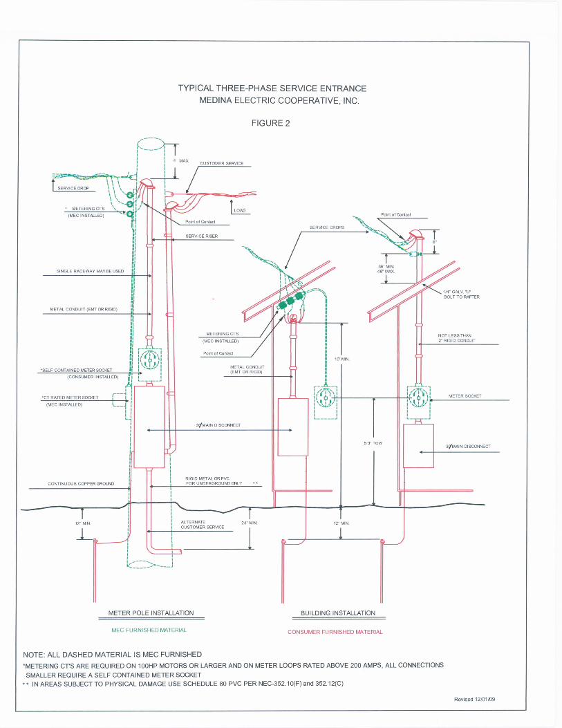
3.0 DEFINITIONS. See Appendix A for a definition of important terms used in this
specification. See also Figures 1 and 2, for illustration of these terms.
4.0 DESIGN AND CONSTRUCTION REQUIREMENTS. All meter loop
equipment shall be weatherproof and be installed by the Member’s electrician.
No consumer-owned meter loops should be installed on Cooperative transformer
poles.

Rev. May 5, 2010 by William Craig Medina Electric Corporative 2
4.1 Meter Pole. Permanent meter poles will be set by the Cooperative. Meter poles
are part of the construction cost and remain the property of the Cooperative.
Meter poles shall not have more than two meter loops. The meter loop shall be
mounted directly on the pole. A wood backing is not allowed on the meter pole.
All mobile homes must use a permanently installed meter pole. Temporary meter
poles for construction are the consumer’s responsibility.
4.2 Service Riser.
Pole Installation - The meter socket shall have a minimum clearance of no less
than 63” and no more than 72” from ground level. The service riser shall extend
to within 4’ of the top of the pole and must be 2” or greater (EMT or RIGID)
conduit for meter loops equal to or greater than 125 amps. For installations where
the rated meter loop is less than 125 amps, the conduit shall be a minimum of
1-1/4” The riser must also be continuous except for necessary couplings. See
Figure 1, (MEC Standards)
Building Installation – Where a service riser rises above roof level it shall extend
beyond that point a minimum of 36” and not to exceed a maximum of 48”
measured from the top of the conduit. Where the service riser stops below roof
level, a minimum of 10-ft vertical clearance is required measured from ground
level to the lowest point on the drip loop (See Figure 1). Risers extending above
roof level shall consist of at least 2” diameter rigid metallic conduit. (MEC
Standards)
4.2.1 Clearances.
Overhead Service-Drop Clearances
(A) Building Clearance
Service conductors shall have a clearance of no less than 3 feet from windows that
are designed to be opened, doors, porches, balconies, ladders, stairs, fire escapes,
or similar locations. (NEC 230.9.A)
(B) Vertical Clearance from Ground
Service-drop conductors shall have the following minimum clearances from the
final grade.
10-ft (3.05 m) – at the electric service entrance to buildings, also at the lowest
point of the drip loop of the building electric entrance, above areas or sidewalks
accessible only to pedestrians and where voltage does not exceed 150 volts to
ground. For other voltages see (NEC 230.24 B2)
12-ft (3.7 m) – over residential property or driveways and those commercial areas
not subject to truck traffic where the voltage does not exceed 300 volts to ground.
For other voltages see (NEC 230.24 B3)

Rev. May 5, 2010 by William Craig Medina Electric Corporative 3
15-ft (4.5 m) – for those areas listed for voltage that exceeds 300 volts to ground
over residential property or driveways and those commercial areas not subject to
truck traffic. (NEC 230.24 B3)
18-ft (5.5m) – over public streets, alleys, roads, state highways and parking areas
subject to truck traffic, driveways on other than residential property, and other
land such as cultivated, grazing, forest, and orchard. (NEC 230.24 B4)
(C) Above Roofs
Conductors shall have a vertical clearance of not less than 8 ft above the roof
surface. (NEC 230.24 A)
EXCEPTON (1): If a roof surface is subject to pedestrian or vehicular traffic then
the clearance requirements shall comply with sections 4.2.1 A and B (NEC
230.24 A Exception 1)
EXCEPTION (2): If the voltage between conductors does not exceed 300 volts,
measured phase to ground, and the roof has a slope of 1:3 (1 vertical unit to 3
horizontal units) or greater, a reduction of roof clearance to 3ft is allowed. (NEC
230.24 A Exception 2)
EXCEPTION (3): If the voltage between conductors does not exceed 300 and the
conductors do not cross more than 4 ft of the overhanging portion of the roof and
are terminated at a through-the-roof raceway or approved support a reduction in
clearance to 18 inches shall be permitted. (NEC 230.24 A Exception 3)
4.3 Service Entrance Conductors. The size of service entrance conductors is
determined by the service equipment disconnecting means name plate rating. If
the name plate is missing or not legible, contact Medina prior to installation. See
Table 1, of single-phase services and Table 1, of three- phase services. (NEC
TABLE 310.15(B)(6), 310.16)
4.3.1 Parallel conductors. Service entrance conductors of size 1/0 and larger,
comprising each phase, polarity, neutral, or grounded circuit conductor shall be
permitted to be paralleled on single-phase and three-phase services (NEC 310.4).
Conductors in parallel are subject to ampacity reduction factors required in NEC
310.15 B2a. The service disconnecting means must have provisions for
terminating paralleled conductors. No double lugging of conductors shall be
permitted on the meter base or service equipment.
4.3.2 Neutral Reduction. The grounded service conductor (neutral) shall not be reduced
on single-phase services (MEC). The neutral may be reduced on three-phase
services where the load served consists only of three-phase motors. (See NEC
220.61, NEC 250.24 C 1 & 2))

Rev. May 5, 2010 by William Craig Medina Electric Corporative 4
4.4 Phasing. Phase markings are to be the correct in color in accordance with the
NEC. For all service connections, the grounded service conductor (neutral) must
be properly marked with phasing tape. (NEC 200.6 B3) On a 4-wire delta service
the high-leg must be permanently marked with orange phasing tape or some other
means. (NEC 110.15)
4.5 Metering. A meter socket will be provided by the Cooperative and installed by
Member for all Services 200 amp and below and motors below 100 Hp. For other
services the Cooperative will provide and install metering current transformers
and a meter socket that are separate from the Member’s service entrance
equipment.
4.6 Service Disconnecting Means. The service disconnecting means shall be
installed at a readily accessible unobstructed location outside a building or
structure with the meter base, unless otherwise approved by Medina’s personnel
prior to installation. Location shall be accessible to Medina’s personnel at all
times. There shall be no more than six disconnects or breakers per service
grouped in any one location in lieu of a single main disconnect. (NEC 230.71) If
multi- breaker is located more than six (6) feet from the meter, the consumer shall
have a main disconnect. Each service disconnect shall be permanently marked to
identify it as a service disconnect. (NEC 230.70B) Only breakers designed,
manufactured, and approved for use as main disconnects will be permitted to be
used as a main disconnect.
4.6.1 Minimum Disconnect Rating. The service disconnect shall have a rating no less
than that of the calculated load or for the type of installation. (NEC 225.39)
(A) One-Circuit Installation. The disconnection means shall be no less than 15
amps. (NEC 225.39A)
(B) Two-Circuit Installation. For installations consisting of not more than two 2
wire branch circuits, the feeder or branch circuit disconnect means shall have a
rating of not less than 30 amps. (NEC 225.39B)
(C) Single Family Dwelling. The 3-wire service disconnect for a one family
dwelling shall be no less than100 amps. (NEC 225.39C)
(D) All Other Installs. For any other type of installs, the means of disconnect
shall not be less than 60 amps. (NEC 225.39D)
4.7 Overcurrent. A fuse or an overcurrent trip unit of a circuit breaker shall be
connected in series with each ungrounded conductor. (NEC 240.15A) Each
ungrounded conductor shall have overcurrent protection. An overcurrent device
shall not exceed the allowable ampacity of the conductor. (NEC 230.90) Use
NEC Table 310.15 B6 for single phase service or NEC table 310.16 for 3-phase
service.

Rev. May 5, 2010 by William Craig Medina Electric Corporative 5
4.8 Circuit Breaker as Overcurrent Device. Circuit breakers shall open all
ungrounded conductors of the circuit, single wire or multiwire, both manually and
automatically.(NEC 240.15 B)
4.8.1 Multiwire Branch Circuit. Except where limited by 210.4(B), individual single-
pole circuit breakers, with or without identified handle ties, shall be permitted as
the protection for each ungrounded conductor of multiwire branch circuits that
serve only single-phase line-to-neutral loads.
4.8.2 3-Phase and 2-Phase Systems. For line-to-line loads in 4-wire, 3-phase systems
or 5-wire, 2-phase systems having a grounded neutral point and no conductor
operating at a voltage greater than rated, individual single-pole circuit breakers
with identified handle ties shall be permitted as the protection for each
ungrounded conductor.
4.9 Grounding. A grounding electrode or grounding electrode system shall be
furnished and installed by Member at each service. See Figure 1 and 2 attached
for illustrations details.
4.9.1 Grounding Electrode. A grounding electrode shall be installed at each service.
The grounding electrode shall consist of a 5/8” diameter by 8’ long copper clad
ground rod. Rods shall be driven to a depth of 12” below ground level in
undisturbed soil. Where rock bottom is encountered ground rods may be driven at
an angle of 45 degrees from the vertical or shall be buried in a trench that is not
less than 2 ½ feet deep. (NEC 250.53 G)
4.9.2 Grounding Electrode System. If available on the premises at each building or
structure served, each item (a) through (d) below as well as the grounding
electrode required in 4.8.1 shall be bonded together to form the grounding
electrode system. Member must consult NEC 250.53 for installation details.
a. Metal Underground Water Pipe
b. Metal Frame of Building
c. Concrete Encased Electrode
d. Ground Ring
4.9.3 Grounding Electrode Conductor. The grounding electrode conductor shall be
copper and sized according to NEC Table 250.66 with #6 being the minimum size
allowed by the Cooperative. The grounding electrode conductor shall be
continuous. (NEC 250.64 C)
4.9.4 Service Disconnect Grounding. The grounding electrode conductor shall be
connected to the grounded service conductor (neutral) at the terminal or bus to
which the grounded service conductor is connected at the service disconnecting
means (neutral bus). A main bonding jumper shall bond the service equipment
enclosure (ground bus) to the neutral bus (NEC 250.24 A-D). The main bonding
jumper shall be connected by screw only identified with a green finish. A copper
conductor sized according to NEC Table 250.66 or a bus jumper can be used as a
suitable main bonding jumper. (NEC 250.28)

Rev. May 5, 2010 by William Craig Medina Electric Corporative 6
4.9.5 Equipment Grounding Conductor. All equipment shall be grounded to the service
ground by means of an equipment-grounding conductor. The equipment-
grounding conductor shall be sized according to NEC Table 250.66
4.9.6 Grounding Mobile Homes. Grounding of both electrical and non-electrical metal
parts in a mobile home shall be through connection to a grounding bus in the
mobile home distribution panel board. The grounding bus shall be grounded
through the green-colored insulated conductor in the supply cord or the feeder
wiring to the service ground in the service-entrance equipment located adjacent to
the mobile home location. Neither the frame of the mobile nor the frame of any
appliance shall be connected to the grounded circuit conductor (neutral) in the
mobile home. Provisions of NEC 550.33(A) requires that the feeder assembly for
a mobile home consist of a listed cord or four color-coded insulated conductors,
one of which is the grounded conductor (white) and one of which is used for
grounding purposes (green). Thus, the grounded and grounding conductors are
kept independent of each other and are connected only at the service equipment
(at the point of connection of the grounding electrode conductor). Grounding of
both electrical and nonelectrical metal parts, including the frame of the mobile
home or the frame of any appliance, is accomplished by connection to the
equipment grounding bus [never to the grounded conductor (neutral bus)]. The
purpose of this requirement is to prevent incidental contact between the grounded
conductor and non-current-carrying metal parts of electrical equipment. Without
the separation of the grounded and grounding conductors, this contact could result
in the metal structure or metal sheathing of the mobile home becoming a parallel
path for the neutral current. Bonding screws, straps, or buses, which bond the
grounded (neutral) circuit conductor to the non-current-carrying metal parts in the
mobile home panelboard or to the metal frame of an appliance (ranges, clothes
dryers), must not be installed or, in the case of ranges and clothes dryer, must be
removed. In general, new ranges and clothes dryer have a factory-installed
bonding jumper. Removal of the factory-installed bonding jumper does not
compromise or void the listing of the product, because isolation of the metal
appliance frame from the grounding circuit conductor is required by the Code.
There is limited application in existing branch circuits of conventional or “site-
built” construction where the factory-installed bonding jumper can remain intact.
Excerpts from NEC 2008 Handbook pages 882-883. Connecting the equipment-
grounding conductor to the grounding bus shall be the responsibility of the
consumer’s electrician. (NEC 550.16)
4.10 Motors. Single-phase motors in excess of ¾ Hp shall be 240 volt. Motors having
a rated capacity in excess of 10 Hp must be three-phase. Motors 100 Hp and over
shall be required to have a split winding or reduced-voltage type starter, including
the replacement of existing motors.
4.11 Motor Overcurrent Protection. An overcurrent trip device shall be rated for no
more than 125% of the full load rating for motors marked with a temperature rise
of less than 40 C or a service factor of 1.15 or greater. All other motors shall have
an overcurrent device that is rated for no more than 115% of the full load. (NEC
430.32)

Rev. May 5, 2010 by William Craig Medina Electric Corporative 7
4.12 Interconnected Electric Power Production Sources. This includes any
installation of one or more electric power production source operating in parallel
with a primary source of electricity. (NEC 705.1)
4.12.1 Equipment Approval. All utility interactive systems shall be approved and listed
for interconnection service. (NEC 705.4) The output of interactive systems shall
be connected phase to phase.(MEC)
4.12.2 Interactive System Disconnecting Means. Means shall be provided to disconnect
power production equipment, such as utility interactive inverters or transformers
associated with a power production source, from all ungrounded conductors of all
sources of supply.(NEC 705.21) The disconnecting means for ungrounded
conductors shall consist of a manually or power operable switch or circuit breaker
with the following features: (NEC 705.22)
1. Located where readily accessible (NEC 705.22.1)
2. Externally operable without exposing the operator to contact with live parts
and, if power operable, of a type that could be opened by hand in the event of
a power supply failure (NEC 705.22.2)
3. Plainly indicating whether in the open (off) or closed (on) position (NEC
705.22.3)
4. Having ratings not less than the load to be carried and the fault current to be
interrupted. For disconnect equipment energized from both sides, a marking
shall be provided to indicate that all contacts of the disconnect equipment
might be energized (NEC 705.22.4)
5. Simultaneous disconnect of all ungrounded conductors of the circuit (NEC
705.22.5)
6. Capable of being locked in the open (off) position (NEC 705.22.6)
4.12.3 Overcurrent Protection. Conductors and overcurrent devices shall be sized to
carry no less than 125 percent of the maximum calculated current. (NEC
705.60.B.1)
4.12.4 Grounding. Interconnected electric power production sources shall be properly
grounded. (NEC 705.50)
4.12.5 Ground-Fault Protection. Here ground-fault protection is used. The output of an
interactive system shall be connected to the supply side of the ground-fault
protection. (NEC 705.32)
4.12.6 Loss of Primary Source. Upon loss of primary source, one or more phases for 3-
phase service, an electric power production source shall be automatically
disconnected from all ungrounded conductors of the primary source and shall not
be reconnected until the primary source is restored. A listed utility-interactive
inverter shall be permitted to automatically cease exporting power upon loss of
primary source and is not required to automatically disconnect all ungrounded
conductors from the primary source. A utility-interactive inverter shall be
permitted to operate as a stand-alone system to supply loads that have been
Rev. May 5, 2010 by William Craig Medina Electric Corporative 8
disconnected from electrical production and distribution network sources. (NEC
705.40 & NEC 705.42)
4.12.7 Unbalanced Single Phase Interconnections. Single-phase inverters shall not be
connected to 3-phase power systems unless the interconnected system is designed
so that significant unbalanced voltages cannot result. (NEC 705.100 A)
4.12.8 Unbalanced Three Phase Interconnections. Three-phase inverters and 3-phase ac
modules in interactive systems shall have all phases automatically de-energized
upon loss of, or unbalanced, voltage in one or more phases unless the
interconnected system is designed such that unbalanced voltages will not result.
(NEC 705.100 B)

THREE
PHASE
U&D
SIZE OF
LOOP
(AMPS)
Non-Power and
Light THHN
Copper
Non-Power
and Light
THHN
Aluminum
Non-Power
and Light
Parallel
Copper
Non-Power
and Light
Parallel
Conduit EMT
or Ridgid
Single Conduit
Size for
Copper
Single Conduit
Size for
Aluminum
60 #6 #4 - - 1.25" 1.25"
70 #4 #3 - - 1.25" 1.25"
100 #2 #1 - - 1.25" 1.25"
125 #1 #2/0 - - 2" 2"
150 #1/0 #3/0 - - 2" 2"
175 #2/0 #4/0 - - 2" 2"
200 #3/0 250 MCM 2-1/0 (2)2" 2" 2"
225 #4/0 300 MCM 2-1/0 (2)2" 2" 2"
250 250 MCM 400 MCM 2-1/0 (2)2" 2.5" 2.5"
300 350 MCM 500 MCM 2-1/0 (2)2" 2.5" 2.5"
350 500 MCM 700 MCM 2-2/0 (2)2" 3" 3"
400 600 MCM 800 MCM 2-3/0 (2)2" 3" 3"
600 2-500 MCM - 2-350 MCM (2)2.5" 4" -
800 - - 2-600 MCM (2)3" - -
1000 - - 2-900 MCM (2)3" - -
MEC Three Phase Non-Power and Light
THHN CONDUCTOR
(Already adjusted
per NEC 310.15 B2a)
Parallel Copper
Conductors and Conduit
(NEC 310.4)
Single Conduit
EMT or Ridgid
(NEC Annex C Table C.8(A))
THREE
PHASE
D
SIZE OF
LOOP
(AMPS)
Power and
Light THHN
Copper
Power and
Light THHN
Aluminum
Power and
Light
Parallel
Copper
Power and
Light
Parallel
Conduit EMT
or Ridgid
Single Conduit
Size for
Copper
Single Conduit
Size for
Aluminum
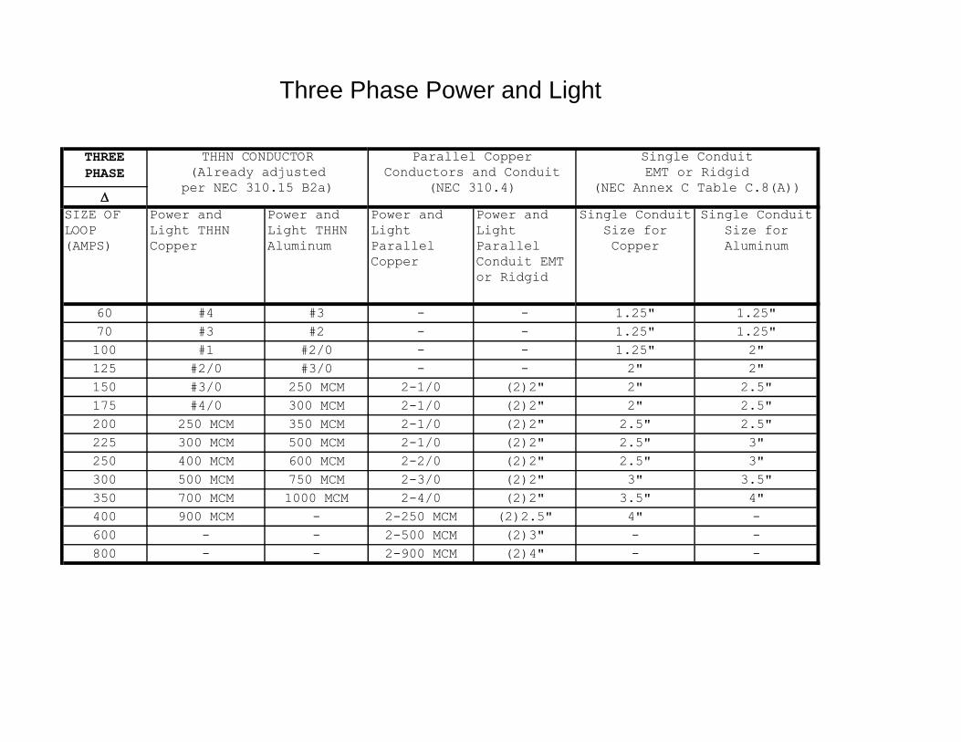
60 #4 #3 - - 1.25" 1.25"
70 #3 #2 - - 1.25" 1.25"
100 #1 #2/0 - - 1.25" 2"
125 #2/0 #3/0 - - 2" 2"
150 #3/0 250 MCM 2-1/0 (2)2" 2" 2.5"
175 #4/0 300 MCM 2-1/0 (2)2" 2" 2.5"
200 250 MCM 350 MCM 2-1/0 (2)2" 2.5" 2.5"
225 300 MCM 500 MCM 2-1/0 (2)2" 2.5" 3"
250 400 MCM 600 MCM 2-2/0 (2)2" 2.5" 3"
300 500 MCM 750 MCM 2-3/0 (2)2" 3" 3.5"
350 700 MCM 1000 MCM 2-4/0 (2)2" 3.5" 4"
400 900 MCM - 2-250 MCM (2)2.5" 4" -
600 - - 2-500 MCM (2)3" - -
800 - - 2-900 MCM (2)4" - -
Three Phase Power and Light
THHN CONDUCTOR
(Already adjusted
per NEC 310.15 B2a)
Parallel Copper
Conductors and Conduit
(NEC 310.4)
Single Conduit
EMT or Ridgid
(NEC Annex C Table C.8(A))

GROUNDING ELECTRODE CONDUCTOR FOR AC SYSTEMS
FROM NEC TABLE 250.66
SIZE OF LARGEST SERVICE
ENTRANCE CONDUCTOR OR
EQUIVALENT AREA FOR PARALLEL
CONDUCTORS
SIZE OF GROUNDING ELECTRODE
CONDUCTOR
COPPER ALUMINUM OR
COPPER-CLAD
ALUMINUM
COPPER ALUMINUM OR
COPER-CLAD
ALUMINUM
1/0 OR
SMALLER
2/0 OR 3/0 #6 #4
2/0 OR 3/0 4/0 OR 250MCM #4 #2
OVER 3/0 THRU
350MCM
OVER 250MCM
THRU 500MCM
#2 1/0
OVER 350MCM
THRU 600MCM
OVER 500MCM
THRU 900MCM
1/0 3/0
OVER 600 THRU
1100 MCM
OVER 900MCM
THRU1750MCM
2/0 4/0
OVER 1100MCM OVER 1750MCM 3/0 250MCM
THIS MATERIAL IS NOT THE COMPLETE AND OFFICIAL POSITION OF
THE NFPA ON THE REFERENCED SUBJECT WHICH IS REPRESENTED ONLY
BY THE STANDARD IN ITS ENTIRETY.

Definitions List
Ampacity - The current, in Amperes, that a conductor can carry continuously
under the conditions of use without exceeding its temperature rating.
Bonding (Bonded) – The permanent joining of metallic parts to form an
electrically conductive path that ensures electrical continuity and the
capacity to conduct safely any current likely to be imposed.
Current Carrying Conductor – Any conductor, grounded or not, that carries
current. The service grounding conductor (neutral) is considered to be a
current carrying conductor.
Disconnecting Means – A device, or group of devices, or other means by
which the conductors of a circuit can be disconnected from their source of
supply. Circuit breakers shall be considered a means of disconnect.
Equipment-Grounding Conductor – The conductor used to connect the non-
current-carrying metal parts of equipment , raceways, and other enclosures
to the system grounded conductor, the grounding electrode conductor, or
both, at the service equipment or at the source of a separately derived
system.
Ground – A conducting connection, whether intentional or accidental,
between an electrical circuit or equipment and the earth or to some
conducting body that serves in place of the earth.
Grounded - Connected to earth or to some conducting body that serves in
place of the earth.
Grounding Electrode – A device that establishes an electrical connection to
earth.
Grounding Electrode Conductor – The conductor used to connect the
grounding electrode to the equipment-grounding conductor, to the grounded
conductor, or to both, at the service, at each building or structure where
supplied by a feeder or branch circuit, or at the source of a separately
derived system.
Interactive System – An electric power production system that is operating
in parallel with and capable of delivering energy to an electric primary
source supply system.

Main Bonding Jumper – The connection between the grounded circuit
conductor and the equipment-grounding conductor at the service.
Overcurrent protection Device – Any device that limits or interrupts current
in a fault or overload condition. Fuses or circuit breakers shall be
considered overcurrent protection.
Phasing – A form of marking conductors to the specified use, voltage, or
phase.
Readily Accessible – The ability for Medina personnel to have unobstructed
access to.
Service-Entrance Conductors, Overhead System – The service conductors
between the terminals of the service equipment and a point usually outside
the building, clear of building walls, where joined by tap or splice to the
service drop.
Ungrounded Conductor – Any conductor that is not properly bonded to a
ground lug, system ground, or equipment ground.