three years of lhc operation : what was really successful ... · what was really successful, and...
TRANSCRIPT


Vacuum, Surfaces & Coatings Group
Technology Department
Three years of LHC operation :
what went wrong ?
what was really successful,
and lessons for the future
V. Baglin on behalf on TE-VSC group CERN TE-VSC, Geneva
2 OLAV-IV, Hsinchu, Taiwan, April 1-4, 2014

Vacuum, Surfaces & Coatings Group
Technology Department 3 OLAV-IV, Hsinchu, Taiwan, April 1-4, 2014
Outline
1. Introduction to LHC
2. Beam Vacuum System
3. Issues During Installation
4. Beam Vacuum System Commissioning
5. Consolidation and Upgrade during LS1
6. Summary

Vacuum, Surfaces & Coatings Group
Technology Department 4 OLAV-IV, Hsinchu, Taiwan, April 1-4, 2014
1. Introduction to LHC

Vacuum, Surfaces & Coatings Group
Technology Department
CERN Accelerators Complex
5 OLAV-IV, Hsinchu, Taiwan, April 1-4, 2014 OLAV-IV, Hsinchu, Taiwan, April 1-4, 2014 5

Vacuum, Surfaces & Coatings Group
Technology Department 6
LHC Layout
OLAV-IV, Hsinchu, Taiwan, April 1-4, 2014

Vacuum, Surfaces & Coatings Group
Technology Department OLAV-IV, Hsinchu, Taiwan, April 1-4,
2014 7
LHC layout : Some numbers
Item Length (m) % wrt to total
Ring circumference 26 642.1 100
<arc length> ~ 2810 84
<LSS length> ~ 515 16
Total length under vacuum 52 232

Vacuum, Surfaces & Coatings Group
Technology Department 8
LHC Current Parameters Design Commissioning
Nominal Ultimate 2010 2011
(Fill 2256)
2012 (Fill 3250)
Energy [TeV] 7 3.5 3.5 4
Luminosity [x1034 cm-2.s-1] 1.0 2.3 0.02 0.36 0.7
Current [mA] 584 860 80 362 420
Proton per bunch [x1011] 1.15 1.7 1.2 1.45 1.7
Number of bunches 2808 368 1380 1378
Bunch spacing [ns] 25 150
(75-50)*
50 (25)*
50 (25)*
Normalised emittance [μm.rad] 3.75 ~ 3 ~ 2.3 ~ 2.2
β * [m] 0.55 3.5 1 0.6
Total crossing angle [μrad] 285 240 240 290
Critical energy [eV] 44.1 5.5 8.2
Photon flux [ph/m/s] 1 1017 1.5 1017 0.06 1017 0.3 1017 0.4 1017
SR power [W/m] 0.22 0.33 0.002 0.01 0.02
Photon dose [ph/m/year] 1 1024 1.5 1024 1 1021 1 1023 1.4 1023
* During MD periods OLAV-IV, Hsinchu, Taiwan, April 1-4, 2014

Vacuum, Surfaces & Coatings Group
Technology Department 9
4th July 2012: SM BEH Boson Discovery
ATLAS and CMS discovered a new boson
in the mass region ~ 125-126 GeV/c2
OLAV-IV, Hsinchu, Taiwan, April 1-4, 2014

Vacuum, Surfaces & Coatings Group
Technology Department IVC-19, Paris, September 9-13, 2013
10
Nobel Prize 2013
The Nobel Prize in Physics 2013 was awarded jointly to François
Englert and Peter W. Higgs "for the theoretical discovery of a
mechanism that contributes to our understanding of the origin of
mass of subatomic particles, and which recently was confirmed
through the discovery of the predicted fundamental particle, by the
ATLAS and CMS experiments at CERN's Large Hadron Collider"
The Laureate during the announce the 4th of July 2012
Vacuum, Surfaces & Coatings Group
Technology Department 11 OLAV-IV, Hsinchu, Taiwan, April 1-4, 2014
2. Beam Vacuum System

Vacuum, Surfaces & Coatings Group
Technology Department 12 OLAV-IV, Hsinchu, Taiwan, April 1-4, 2014
Introduction • Without beam, the LHC vacuum system static pressure is in the UHV-XHV range
• In principle, inside a leak tight cryogenic vacuum system operating at 1.9 K, the pressure level is defined by
the hydrogen vapour pressure (<< 10-19 Torr)
• With circulating beam, the LHC vacuum system dynamic pressure is dominated by 3 sources :
• SR stimulated molecular desorption
• Electron stimulated molecular desorption
• ion stimulated molecular desorption

Vacuum, Surfaces & Coatings Group
Technology Department 13 OLAV-IV, Hsinchu, Taiwan, April 1-4, 2014
Design value : a challenge with circulating beams
• Life time limit due to nuclear scattering ~ 100 h
• n ~ 1015 H2/m3
• <Parc> < 10-8 mbar H2 equivalent
• ~ 80 mW/m heat load in the cold mass due to proton scattering
• Minimise background to the LHC experiments
n c
1
c
E I masscoldP
H2_eq / m3 mbar
<LSS1 or 5> ~ 5 1012 10-10
<ATLAS> ~ 1011 10-11
<CMS> ~ 5 1012 10-10
A. Rossi, CERN LHC PR 783, 2004.

Vacuum, Surfaces & Coatings Group
Technology Department 14
3.1 Cryogenic Temperature
Vacuum System
OLAV-IV, Hsinchu, Taiwan, April 1-4, 2014
Vacuum, Surfaces & Coatings Group
Technology Department
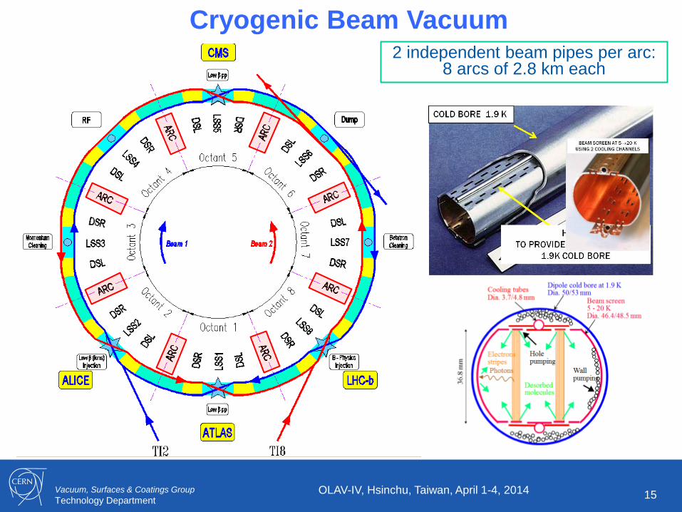
2 independent beam pipes per arc: 8 arcs of 2.8 km each
Cryogenic Beam Vacuum
15 OLAV-IV, Hsinchu, Taiwan, April 1-4, 2014

Vacuum, Surfaces & Coatings Group
Technology Department 16 OLAV-IV, Hsinchu, Taiwan, April 1-4, 2014
Arc : Some Numbers
Item Total
Vacuum sectors (cryogenic) 16
Vacuum sector valves 32
Roughing valves (arc) 844
Ion pumps 0
Bayard Alpert gauges 0
Penning gauges (arc) 108
Pirani gauges 108
Item Length (m)
Unbaked Arc @ cryo T ~ 45 000

Vacuum, Surfaces & Coatings Group
Technology Department 17
LHC : Superconducting Technology
• Cryogenic vacuum system inside the arc
• A beam screen is housed inside the cold bore held at 1.9 K
OLAV-IV, Hsinchu, Taiwan, April 1-4, 2014

Vacuum, Surfaces & Coatings Group
Technology Department 18
LHC Dipole Vacuum System • Cold bore (CB) at 1.9 K which ensures leak tightness
• Beam screen (BS) at 5-20 K which intercepts thermal loads and acts as a screen
Courtesy N. Kos CERN AT/VAC
OLAV-IV, Hsinchu, Taiwan, April 1-4, 2014

Vacuum, Surfaces & Coatings Group
Technology Department 19
LHC Vacuum System Principle
• Molecular desorption stimulated by photon, electron and ion bombardment
• Desorbed molecules are pumped on the beam vacuum chamber
• 100 h beam life time (nuclear scattering) equivalent to ~ 1015 H2/m3 (10-8 Torr H2 at 300 K)
In cryogenic elements
• Molecular physisorption onto cryogenic surfaces
(weak binding energy)
• Molecules with a low recycling yield
are first physisorbed onto the beam screen
(CH4, H2O, CO, CO2) and then onto the
cold bore
• H2 is physisorbed onto the cold bore
Dipole cold bore at 1.9 KDia. 50/53 mm
Beam screen
5 - 20 KDia. 46.4/48.5 mm
Cooling tubes
Dia. 3.7/4.8 mm
Photons
Holepumping
Wall
pumpingDesorbed molecules
Electrons
stripes36
.8 m
m
OLAV-IV, Hsinchu, Taiwan, April 1-4, 2014

Vacuum, Surfaces & Coatings Group
Technology Department 20
2.2 Room Temperature
Vacuum System
OLAV-IV, Hsinchu, Taiwan, April 1-4, 2014

Vacuum, Surfaces & Coatings Group
Technology Department
Room Temperature Beam Vacuum
6 km of RT beam vacuum in
the long straight sections
Extensive use of NEG coatings
Pressure <10-11 mbar
after vacuum activation
21 OLAV-IV, Hsinchu, Taiwan, April 1-4, 2014

Vacuum, Surfaces & Coatings Group
Technology Department 22 OLAV-IV, Hsinchu, Taiwan, April 1-4, 2014
LSS: Some Numbers
Component Total
Vacuum sectors (cryogenic / RT) 88 / 174
Vacuum sector valves (all LHC) 295
Roughing valves (LSS) 309
Ion pumps (special /30 / 60 / 400 l/s) 12 / 550/ 168 / 49
Bayard Alpert gauges (LSS) 178
Penning gauges (LSS) 502
Pirani gauges (LSS) 289
• ~ 85 % of the baked vacuum system is NEG coated
Item in LSS Length (m) % wrt to total
SAM @ cryo T ~ 1 365 19
LSS @ RT baked ~ 1 000 14
LSS @ RT with baked NEG ~ 4 800 67
Total length under vacuum 7 227 100

Vacuum, Surfaces & Coatings Group
Technology Department
23
LHC Long Straight Section Vacuum System
• Focusing inner triplets located around experiments operate at 1.9 K
• Matching sections operate at 4.5 K
• Other components operate at room temperature
“Combined” sector in both side of each experiment
Both beams circulates in the same beam pipe
“Twin” sector
Beams circulate in different beam pipes
Beam screens
OLAV-IV, Hsinchu, Taiwan, April 1-4, 2014

Vacuum, Surfaces & Coatings Group
Technology Department
Kickers
Warm magnets Collimators
LSS Vacuum Sectors Standard Components Installed Inside LSS
24
• Warm magnets, kickers, septum, collimators, beam instrumentation …
Beam Instrumentations
OLAV-IV, Hsinchu, Taiwan, April 1-4, 2014

Vacuum, Surfaces & Coatings Group
Technology Department
Pressure Distribution after NEG Activation
<P> ~ 10-11 mbar
Pressure reading limited by
outgassing of the gauge port and
by the gauge sensitivity
Performances of RT Vacuum Sectors
G. Bregliozzi et al., EPAC Genoa, 2008
25 OLAV-IV, Hsinchu, Taiwan, April 1-4, 2014

Vacuum, Surfaces & Coatings Group
Technology Department
Pressure Distribution after NEG Activation LSS: Performances with Beams
• Reduction throughout the year while increasing beam intensities from 200 to 400 mA
• <PLSS> ~ 7 10-10 mbar
26 OLAV-IV, Hsinchu, Taiwan, April 1-4, 2014

Vacuum, Surfaces & Coatings Group
Technology Department 27
Beam Pipe Installation in ATLAS Before Closure
OLAV-IV, Hsinchu, Taiwan, April 1-4, 2014

Vacuum, Surfaces & Coatings Group
Technology Department 28
CMS Closed and Ready for Beam
OLAV-IV, Hsinchu, Taiwan, April 1-4, 2014

Vacuum, Surfaces & Coatings Group
Technology Department
Pressure Distribution after NEG Activation LHC Experiments: Performances with Beams
• Constant pressure during the year, here, dominated by extremities (VAX area)
• <Pexp> ~ 2 10-10 mbar
29 OLAV-IV, Hsinchu, Taiwan, April 1-4, 2014

Vacuum, Surfaces & Coatings Group
Technology Department 30 OLAV-IV, Hsinchu, Taiwan, April 1-4, 2014
3. Issues During Installation
Vacuum, Surfaces & Coatings Group
Technology Department 31
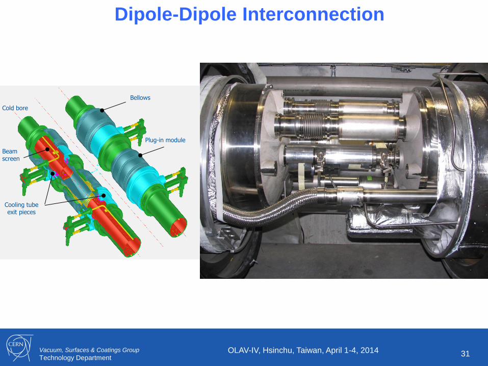
Dipole-Dipole Interconnection
Cold bore
Cooling tube exit pieces
Beam screen
Plug-in module
Bellows
OLAV-IV, Hsinchu, Taiwan, April 1-4, 2014

Vacuum, Surfaces & Coatings Group
Technology Department 32
Plug-in Modules with RF Fingers
• Last installed component to interconnect superconducting magnets (~ 1 700 PIM)
• RF bridge made of sliding RF fingers (Au coated to avoid cold welding)
• < 0.1 mOhm contact resistance, Rh coatiing (i.e. 3 mOhm/RF finger)
RF bellows Copper
transition tube
Upstream flange
Downstream flange
Plug-in module
transition tube
RF-contact Gold
coating 5 m
RF-contact strips
coating 5 m
Indium brazed
RF-contact strips
coating 5 m
Indium brazed
RF-contact
transition flange
Rhodium coating 3 m
Screw & Spring washer
Screw &
Spring
washer
Room temperature position
Working position at cryogenic temperature
Courtesy R. Veness
OLAV-IV, Hsinchu, Taiwan, April 1-4, 2014

Vacuum, Surfaces & Coatings Group
Technology Department 33
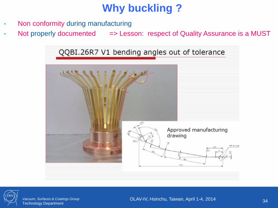
August 2007
• After warm-up of sector 7-8
• A buckled PIM was discovered in interconnect QQBI.26.R7
• Was really found by chance!
OLAV-IV, Hsinchu, Taiwan, April 1-4, 2014
Vacuum, Surfaces & Coatings Group
Technology Department 34
Why buckling ?
• Non conformity during manufacturing
• Not properly documented => Lesson: respect of Quality Assurance is a MUST
OLAV-IV, Hsinchu, Taiwan, April 1-4, 2014

Vacuum, Surfaces & Coatings Group
Technology Department 35
The consequence: RF ball emitter
• Identification of critical PIM :
• Repair / consolidation when possible
• ~ 1 mm longitudinal shift of quadrupole to gain margin
• Maintain arc below 130 K during stand-by period
• Recurrent observation after each warm up of arc with:
• RF ball
• Tomography
• Endoscopes
RF ball RF ball inside PIM A buckled PIM
OLAV-IV, Hsinchu, Taiwan, April 1-4, 2014

Vacuum, Surfaces & Coatings Group
Technology Department
The Sector 3-4 incident (just before the 1st ramp)
19th September 2008 at 11:18.36 last test of the last sector: 7kA (4TeV) towards 9.3 kA (5TeV)
Electrical arc at 8.7 kA in the interconnection Rupture of bellows, expansion of liquid Helium with superinsulation debris
36 OLAV-IV, Hsinchu, Taiwan, April 1-4, 2014

Vacuum, Surfaces & Coatings Group
Technology Department
½ machine done OLAV-IV, Hsinchu, Taiwan, April 1-4, 2014 37
Vacuum, Surfaces & Coatings Group
Technology Department 38
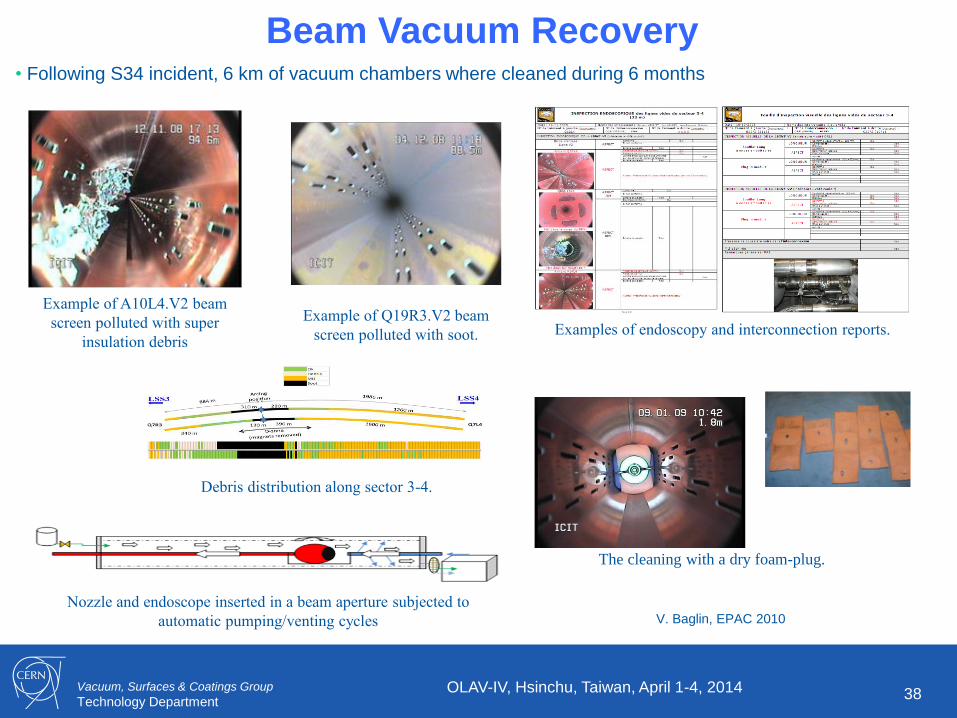
Beam Vacuum Recovery • Following S34 incident, 6 km of vacuum chambers where cleaned during 6 months
OLAV-IV, Hsinchu, Taiwan, April 1-4, 2014
Example of A10L4.V2 beam
screen polluted with super
insulation debris
Example of Q19R3.V2 beam
screen polluted with soot.
Debris distribution along sector 3-4.
Examples of endoscopy and interconnection reports.
Nozzle and endoscope inserted in a beam aperture subjected to
automatic pumping/venting cycles
The cleaning with a dry foam-plug.
V. Baglin, EPAC 2010
Vacuum, Surfaces & Coatings Group
Technology Department 39
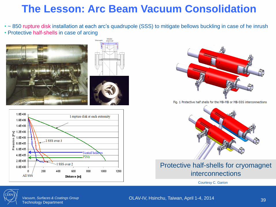
The Lesson: Arc Beam Vacuum Consolidation
• ~ 850 rupture disk installation at each arc’s quadrupole (SSS) to mitigate bellows buckling in case of he inrush
• Protective half-shells in case of arcing
Protective half-shells for cryomagnet
interconnections Courtesy C. Garion
OLAV-IV, Hsinchu, Taiwan, April 1-4, 2014

Vacuum, Surfaces & Coatings Group
Technology Department
Cooling Pipe Repair with Arc at Cryogenic Temperature
40 OLAV-IV, Hsinchu, Taiwan, April 1-4, 2014
• S23 – July 2009 • A He leak of ~0.3 mbar.l/s appeared in insulation vacuum sector VACSEC A7L4.M the 11th of July.
• This sector starts at Q7L3 and finishes at the vacuum barrier at Q11L3
• A partial warm up to 300 K of the arc was decided to repair the leak
Faulty cooling circuit
Located in distribution feedbox DFBA

Vacuum, Surfaces & Coatings Group
Technology Department
Cooling Pipe Repair with Arc at Cryogenic Temperature
41 OLAV-IV, Hsinchu, Taiwan, April 1-4, 2014
• S23 – July 2009 • The PIM located between A12L3 and Q11L3 will be subjected to a gradient of temperature with a high
risk of buckling. The PIM’s name is QBQI.12L3
• The other PIMs between Q11L3 and Q7L3 will be at room temperature
• The remaining arc’s PIMs will have their temperature increasing from 50 to 120 K during the
intervention.
• After repair of the DFBA’s cooling pipe endoscopic inspection of QBQI.12L3 PIMs is required to check
its conformity.
• Beam vacuum was vented with Neon and then the PIM located in QQBI.9L3 was cut to allow the
endoscopy.
PIM QBQI.12L3
Cells at 300 K Rest of the arc with cells at 60 K

Vacuum, Surfaces & Coatings Group
Technology Department
Cooling Pipe Repair with Arc at Cryogenic Temperature
42 OLAV-IV, Hsinchu, Taiwan, April 1-4, 2014
• S23– July 2009 • Endoscopy result : all PIMs from Q7 till QBQI.12L3 were conform: Great !
• But we forgot to inject ultra-pure Neon, we injected only 99.999 % Neon:
• Result ~ 250 Torr.l of impurities were injected in the arc during venting as shown by the ice
• We kept nevertheless the arc cold and observed a nice gas released during the next warm up
of the arc !
• Fortunately, during those time, LHC was not operating with large current !
• Lesson : you need also a bit of luck !
• NB: a similar repair was done in S81 which was vented with ultrapure Ne.

Vacuum, Surfaces & Coatings Group
Technology Department 43 OLAV-IV, Hsinchu, Taiwan, April 1-4, 2014
4. Beam Vacuum
System Commissioning
Vacuum, Surfaces & Coatings Group
Technology Department 44
4.1 Photon Stimulated Molecular
Desorption
Shows Up as Expected
OLAV-IV, Hsinchu, Taiwan, April 1-4, 2014

Vacuum, Surfaces & Coatings Group
Technology Department
First Observation of Synchrotron Radiation: Aug-2010
OLAV-IV, Hsinchu, Taiwan, April 1-4, 2014 45
12/10/2010
04/07/2010
• Pressure rise during the beam
energy ramp
• Dynamic pressure increases with
beam current
• DeltaP = 2 10-10 mbar

Vacuum, Surfaces & Coatings Group
Technology Department 46
4.2 Electron Cloud Build-up
as Expected
OLAV-IV, Hsinchu, Taiwan, April 1-4, 2014
Vacuum, Surfaces & Coatings Group
Technology Department 47
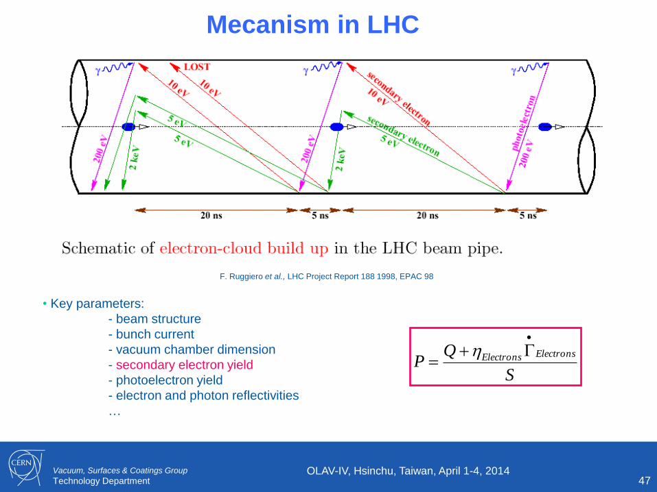
Mecanism in LHC
F. Ruggiero et al., LHC Project Report 188 1998, EPAC 98
• Key parameters:
- beam structure
- bunch current
- vacuum chamber dimension
- secondary electron yield
- photoelectron yield
- electron and photon reflectivities
…
S
QP
ElectronsElectrons
OLAV-IV, Hsinchu, Taiwan, April 1-4, 2014

Vacuum, Surfaces & Coatings Group
Technology Department 48
LHC : Scrubbing of the Surface
1.0
1.2
1.4
1.6
1.8
2.0
2.2
2.4
1.0E-06 1.0E-05 1.0E-04 1.0E-03 1.0E-02 1.0E-01
Dose electrons (C/mm2)
m
ax
0 then 350 V
23 V
44 V
97 V
99 V
340 V
354 V
830 V
350 V
m
ax
V. Baglin et al., Chamonix, 2001
• Photoelectrons produced by SR are accelerated towards the test sample
• Reduction of SEY under electron irradiation is observed
• 1 to 10 mC/mm2 is required
• Growth of a carbon layer (AES, XPS)
maxini
maxfinal
0
0
LHC design:
δmax ~ 1.2
OLAV-IV, Hsinchu, Taiwan, April 1-4, 2014

Vacuum, Surfaces & Coatings Group
Technology Department
First Observation of Electron Cloud : 29-9-2010 • After first successful injections of bunch trains (22/9), pressure rise appeared rapidly
• At 450 GeV : no SR so no PSD
• Delta_P = 5 10-9 mbar
• Dynamic pressure observed ONLY in common beam pipes where the 2 beams
circulates in opposite direction . The 2 beams are needed to trigger the
phenomenon.
OLAV-IV, Hsinchu, Taiwan, April 1-4, 2014 49

Vacuum, Surfaces & Coatings Group
Technology Department
First Observation of Electron Cloud : 29-9-2010 • 368 bunches of 1.2 1011 ppb spaced by 150 ns
• Why a build-up with 150 ns spaced beams (45 m spacing) ?
• Why electron cloud is observed with 150 ns beams ?
OLAV-IV, Hsinchu, Taiwan, April 1-4, 2014 50

Vacuum, Surfaces & Coatings Group
Technology Department
First Observation of Electron Cloud : 29-9-2010
• Bunch spacing by 150 ns = 45 m
• So the 2 opposite bunches which interacted at IP, will encounter again another
bunch at multiples of ½ bunch distance i.e. 22.5, 45, 67.5, 90 m etc.
OLAV-IV, Hsinchu, Taiwan, April 1-4, 2014 51
Tim
e
B1 B2

Vacuum, Surfaces & Coatings Group
Technology Department
Fill 1444
First Observation of Electron Cloud : 29-9-2010
• The position at 45 m from the IP is the longest unbaked area (operating at RT) in
LHC, so the first candidate to trigger electron cloud ….
OLAV-IV, Hsinchu, Taiwan, April 1-4, 2014 52
D1
ITL1
Magnetic field of solenoid≈ 20 Gauss
Solenoid OFF
Solenoid ON 10-7
10-8
10-9
10-10

Vacuum, Surfaces & Coatings Group
Technology Department
2011 Scrubbing Run with 50 ns Bunch Spacing
• As expected, strong pressure reduction with time were observed
• Which allowed to fill-in the machine with nominal parameters the 7-12-2012 with 25
ns bunch spacing
OLAV-IV, Hsinchu, Taiwan, April 1-4, 2014 53

Vacuum, Surfaces & Coatings Group
Technology Department
No multipacting in NEG chambers : ID80
• With the solenoids we could also demonstrated the absence of electron cloud build up in the NEG coated vacuum chambers
A real fairy tale of understanding !
OLAV-IV, Hsinchu, Taiwan, April 1-4, 2014 54
• Switching ON (to 10 A) the solenoids around NEG beam pipe has no effect on the pressure reading (VRPMB.84.6L1)
• Switching ON to 1 A (~6 G) the solenoid around the warm module decreases the pressure from 7 to 3 10-9 mbar
(VRPMB.85.6L1).
Secondary Electron Yield
C. Scheuerlein et al. Appl.Surf.Sci 172(2001)

Vacuum, Surfaces & Coatings Group
Technology Department
But ….
• Our colleagues from the machine operation and physics groups had a clever idea :
• Installing a solenoid everywhere in the machine to mitigate electron cloud !
• So, in Nov 2010, we had to proposed the installation of solenoids around
experimental areas i.e. 20 km of cable to wound around vacuum chambers !
• ~ 350 man.days of work, so 2 teams during ~ 4 months !
•
OLAV-IV, Hsinchu, Taiwan, April 1-4, 2014 55

Vacuum, Surfaces & Coatings Group
Technology Department 56
4.3 Today’s Performances
OLAV-IV, Hsinchu, Taiwan, April 1-4, 2014

Vacuum, Surfaces & Coatings Group
Technology Department 57
Cleaning Effect under SR
• Arc extremity’s vacuum gauges : unbaked Cu and cryogenic beam screen
• Reduction by 2 orders of magnitude since October 2010
• Inside the arc, at 5-20 K, deltaP < 10-10 mbar (i.e. below detection limit)
• The photodesorption yield at cryogenic temperature is estimated to be < 10-4 molecules/photon
• 2 trends :
- Room temperature
- Cryogenic temperature
OLAV-IV, Hsinchu, Taiwan, April 1-4, 2014

Vacuum, Surfaces & Coatings Group
Technology Department
Beam Scrubbing / Conditionning • Measurements in the arc
• Dynamic pressure : reduction of 2 orders of magnitude since 2011
OLAV-IV, Hsinchu, Taiwan, April 1-4, 2014 58
•The electron desorption yield at cryogenic temperature is estimated to be < 5 10-4 molecules/e

Vacuum, Surfaces & Coatings Group
Technology Department
Pressure Distribution after NEG Activation Evaluation of NEG coating ageing in LHC
G. Bregliozzi et al., IPAC Shangai, 2013
59 OLAV-IV, Hsinchu, Taiwan, April 1-4, 2014
Evolution of pressure [mbar]
Year ≈ 0 > 1E-12 > 1E-11 > 1E-10 > 1E-9
2010 72 % 13 % 15 % 1 % 0 %
2011 39 % 32 % 17 % 11 % 1 %
2012 25 % 40 % 18 % 14 % 3 %
28 vacuum sectors mainly in:
1. LSS4 due to component exchange
2. LSS7 Collimator outgassing
Pressure increase ≈ NEG losing performances
• With time, the static pressure in vacuum sector degrades due to partial saturation
of the NEG coating

Vacuum, Surfaces & Coatings Group
Technology Department
Pressure Distribution after NEG Activation NEG coating ageing in LHC : example around collimators
G. Bregliozzi et al., IPAC Shangai, 2013
60 OLAV-IV, Hsinchu, Taiwan, April 1-4, 2014
• The NEG starts to be saturated due to the collimator outgassing.
• Since 2 ion pumps are located around the collimator, the NEG saturation speed is
strongly reduced when the apparent pumping speed of the NEG at the collimator
level is negligible as compared to the pumping speed of the ion pump

Vacuum, Surfaces & Coatings Group
Technology Department 61
4.3 Mistakes, Failures
and Repairs
OLAV-IV, Hsinchu, Taiwan, April 1-4, 2014

Vacuum, Surfaces & Coatings Group
Technology Department
October 2010: Injection Septa in A6L2.B
• Reverse mounting of a vacuum module during installation
• Unfortunately, that was the injection area so RF fingers started to be damaged by the
incoming beam. A bump was needed to inject properly into LHC !
• Ultra-pure Ne venting 19-10-2010 (wk42), allowed to resume operation in 3 days
OLAV-IV, Hsinchu, Taiwan, April 1-4, 2014 62
Injecting B1
Transition tube installed in
reversed position RF fingers

Vacuum, Surfaces & Coatings Group
Technology Department
April 2011: Pressures around Q5L1.B
• We observed, regularly, a singular vacuum behavior in Q5L1.B : which triggered beam dump
1020b •Is it a vacuum gauge or an ion pump
which produce outgassing ?
• In front of our ignorance, we
increased the interlock level to
10-4 mbar !
• X-ray (12/9/2011) showed a reduced
aperture
• We repaired during the winter technical stop
2011-12

Vacuum, Surfaces & Coatings Group
Technology Department 64
Fix of Non-Conformities during LS1 (2013-14) • As a consequence of the 2 previous observations, a systematic X-ray analysis of all the vacuum
modules was done: 1800 X-rays were taken during 2 years.
• The repair of 96 non-conform vacuum modules (~ 5% of total) is needed to restore machine
impedance and to avoid pressure spikes/excursion
• 52 RT vacuum sectors impacted out of which 29 are opened during LS1 on purpose ( ~ 200 kCHf
manpower)
• LESSON : 1) Write down and execute properly the installation procedures with activity reports
2) Implement a quality assurance team
Conform
Courtesy A. Vidal, J-M. Dalin EN-MME
OLAV-IV, Hsinchu, Taiwan, April 1-4, 2014
Non-conform:
reduction of aperture
with increase of contact
resistance

Vacuum, Surfaces & Coatings Group
Technology Department
Summer 2011 : Vacuum Modules - VMTSA
• Design extrapolated and not mechanically validated before installation in the ring
• Pressure spikes located beside inner triplets generated interlocks and background
OLAV-IV, Hsinchu, Taiwan, April 1-4, 2014 65
Observed Pressure spikes during a physics fill
Vacuum, Surfaces & Coatings Group
Technology Department
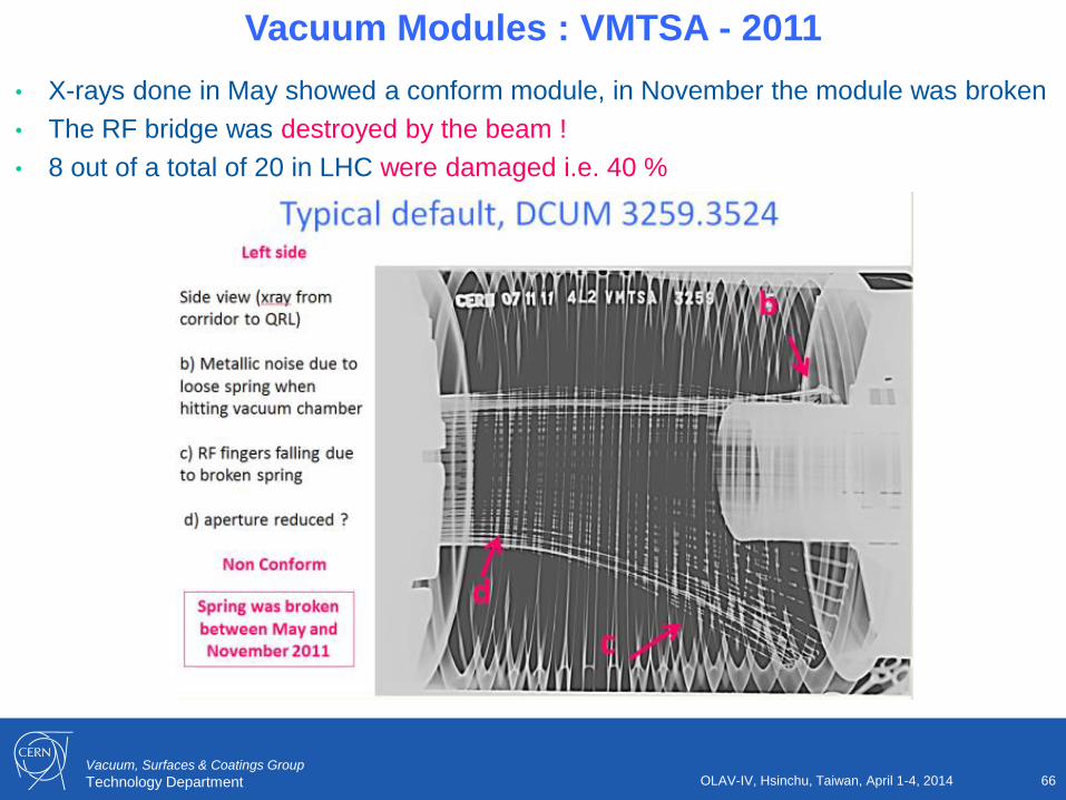
Vacuum Modules : VMTSA - 2011
• X-rays done in May showed a conform module, in November the module was broken
• The RF bridge was destroyed by the beam !
• 8 out of a total of 20 in LHC were damaged i.e. 40 %
OLAV-IV, Hsinchu, Taiwan, April 1-4, 2014 66

Vacuum, Surfaces & Coatings Group
Technology Department
Vacuum Modules : VMTSA - 2011 • Again repair during winter technical stop 2011-12
• Origin of the systematic default was identified to be due to a poor contact between the RF finger and the transition tube. The RF fingers were stiffened for 2012 consolidation.
• For LS1, the layout was modified to remove the badly design module
• LESSON : always mechanically validate the design of components (even under schedule pressure)
OLAV-IV, Hsinchu, Taiwan, April 1-4, 2014 67
• Permanently deformed
fingers
• Spring brazed to the finger
Vacuum, Surfaces & Coatings Group
Technology Department
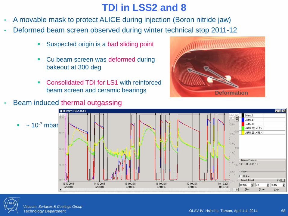
• A movable mask to protect ALICE during injection (Boron nitride jaw)
• Deformed beam screen observed during winter technical stop 2011-12
• Beam induced thermal outgassing
TDI in LSS2 and 8
OLAV-IV, Hsinchu, Taiwan, April 1-4, 2014 68
Suspected origin is a bad sliding point
Cu beam screen was deformed during
bakeout at 300 deg
Consolidated TDI for LS1 with reinforced
beam screen and ceramic bearings Deformation
~ 10-7 mbar

Vacuum, Surfaces & Coatings Group
Technology Department
ALICE : A Large Ion Collider Experiment
• An Ion Collider Experiment which make physics with protons as well !
=> Do not be naïve like me and simply trust the name of an experiment !
• Was not designed to operate with protons ….
• Our friend beam induced multipacting explains why background was observed in
ALICE with 50 ns bunch spaced protons beams
OLAV-IV, Hsinchu, Taiwan, April 1-4, 2014 69
100 150 200 250 300 350 40010
5
106
107
108
109
1010
r [mm]
Max n
. e
- pe
r u
nit
len
gth
[m
-1]
max
=1.4
max
=1.5
max
=1.6
max
=1.7
max
=1.8
2r
Very small electron cloud in the 800mm chamber Due to counter rotating beams, several bunch spacing exist In the OD800 chamber leading to multipacting even with 50 ns
Courtesy G. Iadarola BE/ABP

Vacuum, Surfaces & Coatings Group
Technology Department
ALICE : The Struggle with Beam Scrubbing
• To properly operate with protons ALICE needs POD800 < 2 10-8 mbar
• Left side and right side of the IP behaves differently
• Right side scrubs as expected but the left side is dominated by TDI !
OLAV-IV, Hsinchu, Taiwan, April 1-4, 2014 70
OD800
TDI2L 2 10-8 mbar

Vacuum, Surfaces & Coatings Group
Technology Department
ALICE Extended : LS1 Consolidation
OLAV-IV, Hsinchu, Taiwan, April 1-4, 2014 71
• ID 800 upgrade :
• NEG coated liners along ID800
• TDI sectorisation:
• allows exchange
• allows long bakeout
• 2 000 l/s NEG cartridges
LESSON : Oblige your clients to write down
their performance’s objectives

Vacuum, Surfaces & Coatings Group
Technology Department 72
4.5 CMS repair under Ne atmosphere
OLAV-IV, Hsinchu, Taiwan, April 1-4, 2014

Vacuum, Surfaces & Coatings Group
Technology Department
Document and Record of Informations
• During the show-up of electron cloud and scrubbing run, large pressure rise were observed in CMS till a few 10-7 mbar
• The issue was identified and associated (like many other phenomenon) to electron cloud but not followed closely afterward….
OLAV-IV, Hsinchu, Taiwan, April 1-4, 2014 73

Vacuum, Surfaces & Coatings Group
Technology Department
2011: Pressure spikes in right side of CMS
74
• In 2011, frequent pressure spikes, some up to 10-6 mbar, were observed at CMS, 18 m, right side.
• When the local pressure was above 10-8 mbar, CMS background was larger than 100 % thereby reducing
the detector capability
Fill 2241 with 50 ns bunch spacing
Typical Observation
OLAV-IV, Hsinchu, Taiwan, April 1-4, 2014

Vacuum, Surfaces & Coatings Group
Technology Department
Pressure spikes: CMS
75
• During the winter technical stop 2011-2012, a non-conform vacuum module was identified
by X-ray
• The origin of this NC is due to a mis-positionning of
the TAS-56 vacuum chamber
• To avoid the risk of further aperture reduction, a
repair under Ne atmosphere was done
• This method avoided the full bake out of the CMS
vacuum sector which would have meant dismounting
the central detector !
• A new RF insert, with an additional 20 mm thick
copper ring was made to compensate the mis-
positionning
Courtesy J-M. Dalin EN-MME
OLAV-IV, Hsinchu, Taiwan, April 1-4, 2014

Vacuum, Surfaces & Coatings Group
Technology Department
CMS: Repair under Ne
76
• The vacuum system was over pressurised to + 200 mbar to minimised air backstreaming
into the NEG chambers
• The CMS forward vacuum chamber was opened and moved away for inspection
• And the RF insert exchanged
OLAV-IV, Hsinchu, Taiwan, April 1-4, 2014

Vacuum, Surfaces & Coatings Group
Technology Department
CMS: Ne pump down and NEG activation
77
• Once the flanges closed, Ne was evacuated by a mobile pumping group located at Q1R5
• 10-9 mbar was reached after 2 days indicating that NEG chamber located at the IP were still
pumping
• CMS forward chamber and vacuum chambers located upstream (CT2) and downstream
(TAS) were re-activated
• X-ray were taken after bake out
Q1R5 IP5
CMS
forward
chamber CT2
chamber
HF
chamber
Baking
TAS
• Achieved pressure are < 1 10-10 mbar
• Transmission from – 18 till + 18 m
equals 3500
3500
The CMS IP chambers are still activated
The vacuum performance are restored
10-10
OLAV-IV, Hsinchu, Taiwan, April 1-4, 2014

Vacuum, Surfaces & Coatings Group
Technology Department 78 OLAV-IV, Hsinchu, Taiwan, April 1-4, 2014
5. Consolidation and
Upgrade during LS1

Vacuum, Surfaces & Coatings Group
Technology Department 79 OLAV-IV, Hsinchu, Taiwan, April 1-4, 2014

Vacuum, Surfaces & Coatings Group
Technology Department 80
Long Shutdown 1 (LS1)
• Main aim : consolidate the splice interconnection between superconducting magnets to allow operation at
7 TeV/beam
• Started Feb 2013, Physics will resume April 2015
OLAV-IV, Hsinchu, Taiwan, April 1-4, 2014

Vacuum, Surfaces & Coatings Group
Technology Department 81
Overview of LSS Beam Vacuum Activities
• 148 vacuum sector to re-commission i.e. 5.1 km of vacuum system (80 % of the LSS)
OLAV-IV, Hsinchu, Taiwan, April 1-4, 2014

Vacuum, Surfaces & Coatings Group
Technology Department 82
Consolidations
• Consolidation of pumping scheme, main activities :
• reduce background to the experiments:
• NEG coating of RF bridges inserts located inside and in the vicinity of the LHC
experiments
• 180 inserts to replace
• minimise impact of radiation onto the personnel:
• installation of remotely powered NEG cartridge as complementary lumped pumping
system in collimators areas
• 190 D400 NEG cartridges to install
• Consolidation of diagnostic scheme, main activities :
• Installation of electron cloud pilot sector
• Installation of NEG pilot sector :
•Characterisation of NEG by H2 transmission
Courtesy G. Bregliozzi
OLAV-IV, Hsinchu, Taiwan, April 1-4, 2014

Vacuum, Surfaces & Coatings Group
Technology Department 83
• Aperture reduction of experimental beam pipes at ALTAS and CMS interaction points:
• Diameter reduction from 58 to 47 mm
• install detectors closer to the vertex point
• Full opening of the detectors to exchange the chambers
Upgrade of Experiments
OLAV-IV, Hsinchu, Taiwan, April 1-4, 2014

Vacuum, Surfaces & Coatings Group
Technology Department 84 OLAV-IV, Hsinchu, Taiwan, April 1-4, 2014
6. Summary

Vacuum, Surfaces & Coatings Group
Technology Department 85
Summary
• The LHC vacuum system is made of :
• cryogenic systems (1,9 K – 5 to 20 K)
• baked systems
• NEG coating
• The LHC vacuum system has been designed to deal with:
• static sources of gases (metallic and graphitic surfaces)
• dynamic sources of gases (ions, photons and electrons loads)
• The LHC vacuum system is presently operating as expected
• Some QAP issues but no design issue
• During installation and commissioning phases, innovative solutions have been developed:
• RF ball
• Ne venting
• Activities are conducted during 2013-2014 long shutdown to:
• repair, consolidate and upgrade
OLAV-IV, Hsinchu, Taiwan, April 1-4, 2014

Vacuum, Surfaces & Coatings Group
Technology Department 86 OLAV-IV, Hsinchu, Taiwan, April 1-4, 2014
Acknowledgments
• Many thanks to the CERN and external collaborators who participated to the design and installation of the
LHC vacuum system under the successive directions of A.G. Mathewson, O. Gröbner and P. Strubin
• Warm thanks also to J M. Jimenez for the constant support and to the TE-VSC-LBV team for its investment
and constant commitment during commissioning of the LHC.

Vacuum, Surfaces & Coatings Group
Technology Department 87 OLAV-IV, Hsinchu, Taiwan, April 1-4, 2014
In memory of Roger Calder 1934 – 22 Feb 2014
• Who, among other important
contributions such as vacuum firing
and glow-discharge for the ISR,
invented the ‘perforated beam screen’
in the LHC
Vacuum, Surfaces & Coatings Group
Technology Department 88 OLAV-IV, Hsinchu, Taiwan, April 1-4, 2014
Thank you for your attention !
