throttled valve cavitation and erosionthrottle rhr flow. excessive throttling of the valve had...
TRANSCRIPT

ORNLINRCILTR-91/25
Throttled Valve Cavitation and Erosion
Don Casada
Nuclear Plant Aging ProgramOak Ridge National Laboratory
Oak Ridge, Tennessee
December, 1991
NRC Technical Monitor: Bill Farmer /

ORNL/NRC/LTR-91/25
Throttled Valve Cavitation and Erosion
Don Casada
Nuclear Plant Aging ProgramOak Ridge National Laboratory
Oak Ridge, Tennessee
December 13, 1991
Research sponsored by the Office of Nuclear Regulatory Commission under Interagency Agreement DOE1886402-81B with the US. Department of Energy under contract No. DE-AC05-840R21400 with theMartin Marietta Energy Systens, Inc.
The submitted manuscipt has been authored by a contmrctor of the US. Government under contract No.DE-AC05-840R21400. Accordingly, the U. S. Government retains a nonexclusive royalty-free license topublish or reproduce the published form of the contribution, or aflow others to do so, for US. Governmentpupose&

1. Background
In November of 1988, Brunswick plant maintenance personnel discovered significantlocalized erosion of the valve body of a Unit I Residual Heat Removal (RHR) valve, 1-El 1-F017B (the maintenance was being performed to repair the valve stem and back seat).1
The F017B valv'e is a 20-inch Rockwell angle globe valve that has been historically used tothrottle RHR flow. Excessive throttling of the valve had resulted in cavitation-inducederosion damage to areas immediately downstream of the seat. Subsequent investigationindicated that erosion of valve bodies was a generic concern for the other RHR valves usedin the same service (FO17A on Unit I and F017A and F017B on Unit 2).
Brunswick personnel expanded the investigation to include another set of RHR valves thathad also been used in throttling service. The F024A and F024B valves (from both Units),which are used for Suppression Pool Cooling, were also found to have been damaged bycavitation erosion. These valves aie 16-inch'Anchor Darling globe valves.
Testing of the F017 valves indicated that cavitation was most prevalent in lower flowranges, but existed throughout the range of 4,000 to 16,000 gpm. Testing of the F024valves indicated cavitation present throughout the range of 4,500 to 15,000 gpm, and wasmost prevalent at higher flow rates. It was also noted that the location of the cavitationmoved throughout the body as flow changed.
Subsequent investigation of seven other valves used in safety-related throttling service,including Core Spray (CS), High Pressure Coolant Injection (HPCI), and Reactor CoreIsolation Cooling (RCIC) systems, revealed that one other valve, the HPCI system fullflow test isolation valve F008, had experienced notable erosion.
The Nuclear Regulatory Commission (NRC) issued Information Notice 89-01 in responseto this event. The Reactor Operations Analysis Branch also performed a review ofprevious NRC reports and equipment failure data (Licensee Event Report and Nuclear PlantReliability Data System databases) and issued a technical report documenting the results.2
Because erosion is an aging-related concern, the NRC requested that Oak Ridge NationalLaboratory perform an assessment of the significance of valve body erosion, with theprincipal focus of the review to be the identification of valve types and applicationssusceptible to erosion problems.
2. Valve Erosion Mechanisms
Four principal sources of erosion in valves have been identified:3
* abrasive particles,* high liquid velocity impingement,* erosion-corrosion, and* cavitation.
I

Depending upon the nature of the service conditions, one or more of these erosive sourcesmay exist in nuclear plant valves.
Abrasive particles are primarily a concern in service and other raw-water systems.Abrasion is not viewed to bea major source of concern relative to wall thinning, althoughsome plants have noted increased valve seat and disc wear problems due to high sedimentcontent of the water.
High liquid velocity impingement and erosive-corrosive wear occurs when high velocityfluid impinges on valve or pipe surfaces. In the case of erosion-corrosion, the protectivecorrosion layer that naturally forms is continually removed as it is formed. Thesephenomena have been largely responsible for pipe and valve body failures that haveoccurred in secondary plant (steam and feedwater) systems.
The last erosion mechanism, cavitation, is the principal factor of concern relative to thewear of valve bodies and downstream piping in conjunction with throttled valve service.
Cavitation is a two-stage phenomenon involving:(1) flashing of the liquid due to the pressure of the liquid dropping below the saturation
pressure, and(2) subsequent collapse of the vapor back into liquid due to pressure recovery.
In a valve (see Figure 1), the pressure is reduced as the fluid passes through the minimumflow area (and thus the region of highest velocity), which is typically near the seat. If thepressure reduction is sufficient, saturation conditions can be reached, even for relativelylow temperature service conditions (<100°1F), and at least a portion of the fluid isvaporized. As the fluid exits the seat area, the flow area is rapidly restored, and as a result,a portion of the pressure drop is recovered. If the downstream pressure is greater than thesaturation pressure, the vapor pockets are rapidly collapsed back to the liquid phase.
L.
pvc2PI, -- --- -. ... ... ..
%_J 11
PV ------- ,\< -
PVC
Figure 1. Pressure Recovery Profiles for Globe and Butterfly Valves
2

The pressure profile shown in Figure 1 indicates that the fluid pressure, initially at anupstream pressure of PI, drops in pressure to Pvc as it passes through the valve's venacontracta. PVC is greater than the fluid vapor pressure (Pv) in the case of the globe valve(on left), while Pvc for the butterfly valve (on right) is less than the vapor pressure,resulting in fluid vaporization. As the fluid passes on through the butterfly valve until theeffective flow area is larger, its pressure is recovered to P2, which is greater than the vaporpressure, resulting in collapse of the vapor back to liquid phase. Note that the recoveredpressure for the butterfly valve, that is P2 - PVC, is greater than for the globe valve.Butterfly valves, along with conventional ball valves, are commonly referred to-as "highpressure recovery valves" due to the fact that the pressure recovered is relatively high(compared to, for example, globe valves).
It is primarily in the collapse of the vapor that damage is incurred. Localized pressures ashigh as 100,000 psi have been reported in conjunction with cavitation.3 It is theorized thatwhen the bubbles collapse near a metal surface, such as the valve body wall, a"hammering" of the metal occurs which locally fatigues the material. Other explanationshave been proposed; however, regardless of the mechanism, the fact remains that local
,cavitation removes metal.
3. Cavitation Results
As noted above, cavitation can result in erosion of valve parts, including the valve body,and for some valve designs, ,such as butterfly valves, the erosion can occur in downstreampiping. The location of cavitation damage is dependent upon a variety of factors, includingvalve geometry and flow conditions.
Incipient cavitation is characterized by a relatively low-level "hissing" sound. Fullydeveloped cavitation is much louder and sounds like marbles or gravel flowing through thesystem. The cavitation may also result in considerable system vibration, depending uponcavitation level, how well the piping is supported, and other factors. System vibrationeffects may be manifested in other active components, such as other system valves or eventhe system pump(s).4 The vibration levels encountered under severe cavitation have beenhigh enough to result in a variety of vibration-induced failures, including drain/vent linecracking, valve leak-off tubing failure, and loosening of limit switches, packing followersand other valve components.
Cavitation erosion damage is characterized by a very rough, sometimes pock-markedappearance (as opposed to the smooth wear patterns often associated with high-velocitywear). The damage may be localized or may cover a relatively broad area (a few squareinches).At Brunswick, the erosion was found immediately downstream of the valve seats. For theangle globe valves (F017 set), the erosion occurred in two regions on either side of thecenter guide just above the seat (flow comes from under the plug, and makes a 90° turnabove the seat). In the case of the straight globe valves (1024 set), the erosion was againjust above the seat (flow comes from under the seat); however, it occurred in severalregions around the full circumference of the seat
3
Erosion damage associated with cavitation from throttled butterfly valves may bemanifested in the piping downstream of the valve, instead of the valve body itself, due tothe minimal axial length of butterfly valves. Erosion damage associated with pumprecirculation valves (particularly for high energy pumps, such as main feedwater pumps)may occur farther downstream (the result of high velocity impingement in some cases).
Erosion can eventually result in through-wall failures. These failures can progress rapidlyif a system transient results in a sudden hydraulic or mechanical load (internal pressurespike, for example). Alternatively, the failures may show up as pin-hole leaks that can becorrected before the consequences become more significant.
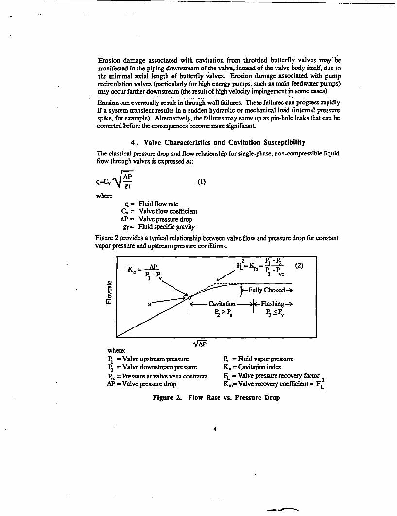
4. Valve Characteristics and Cavitation Susceptibility
The classical pressure drop and flow relationship for single-phase, non-compressible liquidflow through valves is expressed as:
q=C, AP (1)
whereq = Fluid flow rate
C, = Valve flow coefficientAP = Valve pressure dropgf = Fluid specific gravity
Figure 2 provides a typical relationship between valve flow and pressure drop for constantvapor pressure and upstream pressure conditions.
Kc PI - PFL=K=(2
C ....... P <P-p ~ ~ >
where:PI = Valve upstream pressure Pv = Fluid vapor pressureP2 = Valve downstream pressure Kc = Cavitation indexPvc = Pressure at valve vena contracts FL = Valve pressure recovery factor 2AP = Valve pressure drop Km= Valve recovery coefficient = FL
Figure 2. Flow Rate vs. Pressure Drop
4

As is the case for other fluid system components, the flow through valves is generallyproportional to the square root of the pressure drop. This relationship is valid so long asthe fluid is not vaporized. However, as the pressure drops below the vapor pressure,departure from the relationship occurs. As can be seen, the departure from the square rootproportionality occurs at point a of Figure 2. The dimensionless parameter Kc, called thecavitation index, which is calculated at this point, has been used to indicate this point ofdeparture. It provides a somewhat limited indication of the point of cavitation initiation;measurements that have been iiade using acoustical and vibration instrumentation haveindicated that cavitation begins at pressure drops lower than that associated with the valvecoefficient departure from the characteristically linear relationship of flow and Vi.
A characteristic of importance when considering the susceptibility of a valve to cavitation isthe valve pressure recovery factor, FL (alternatively may be expressed as Km which equalsthe square of FL), which accounts for the influence of the valve geometry on its capacity atchoked flow conditions, and is calculated at the intersection of the extension of the constantflow line corresponding to choked flow for the given upstream pressure and the extensionof the square root proportionality curve (see Figure 2). Note that FL can be calculatedbased on readily measurable parameters, except for the vena contracta pressure, Pvc.
Because the vena contracta pressure is not readily measurable, a relationship between thevapor pressure, the fluid critical pressure, and the vena contracts pressure under chokedflow conditions has been derived, and can be expressed as: 5
Pvc = FFPv (3)
where:
FF = Fluid critical pressure ratio factor
FF can be predicted by the following:5
FF= 0.96-0.28 -Pv (4)
where:
Pv = Fluid vapor pressurePc = Fluid critical pressure
Equations 2 and 3 can be combined and rearranged to the following expression:
,Pm= F 2 (Pi - FFPV) (5)
where:
* Note that for most practical applications involving wate. FF is equal to 0.96, since «t vapor presure isnegligible compared to the critical poiure.
5
APm= The maximum rP for which increased flow results for a given upstream pressure(i.e., corresponds to the point at which flow becomes choked)
Equation 5 is referred to as the Choked Flow Equation. It has been used to determineallowable pressure drops for valves to avoid cavitation damage. The BWR Owner's Grouphas established a criterion of valve AP of < 0.8 * APm as the first cut in a set of evaluationcriteria for valves used in throttled service. If this criterion is not met further monitoring todetect the presence and extent of cavitation is required. Based on conversations with utilitypersonnel, this has proved to be a reliable criterion for globe valves, although it was notedthat cavitation conditions can exist even if the criterion is met.
Typical valve pressure recovery factors are:5
Valve type FL
Single port globe 0.9Contoured plug angle 0.9Segmented ball 0.690-degree offset seat butterfly 0.6
It is important to note that high pressure recovery valves have low pressure recoveryfactors. It can be seen from equation 5 and the above pressure recovery factors that globeand angle valves can be operated with greater pressure drops than can ball or butterflyvalves. More specific information on allowable pressure drops for different valve types isprovided below in Section 5.
5. General Valve Type and Material Considerations
5.1 Valve Types
It was noted in Section 2 that some valves, such as butterfly and ball valves, are referred toas "high pressure recovery valves" due to the fact that a significant portion of the pressuredrop that occurs from upstream of the valve to the valve's vena contracta is recovered in thedischarge.
As can be seen from Equation 5, the greater the pressure recovery factor FL, the greater isthe maximum AP. To illustrate the effect that the type of valve has on the maximumallowable pressure drop for the BWR Owner's Group guideline of 0.8 * APm, consider theresults provided in Table 1, which are based on representative valves from a commercialvalve supplier's valve sizing program.6 Conditions that are typical of valve applicationsfor emergency service water (ESW) and RHR valves are used.
6

Table 1. Comparison of Maximum Pressure Drops for Valve Types
System Valve Type % Open APm APaut/APm
ESW Globe 69 73 0.68
Butterfly 19 57 0.88
Full-Bore Ball 29 65 0.77Q-trim Ball 43 74 0.67
RHR Case 1 Globe 66 227 0.66Butterfly 18 178 0.84
Full-Bore Ball 25 201 0.75
Q-trim Ball 39 232 0.65
RHR Case 2 Globe 71 225 0.67
Butterfly 21 175 0.86
Full-Bore Ball 31 199 0.75Q-trinm Ball 46 227 0.66
*0ap = Actual aP
The assumed conditions for Table 1 are:
Application q, gpm d, in. Pi, psia P2, psia T, SF
ESW 5000 16 80 30 80
RHR Case 1 3000 10 250 100 150
RHR Case 2 10000 16 250 100 150
'It can be seen from Table 1 that the maximum allowable pressure drops across simple balland butterfly valves are less than those for globe or Q-trim ball valves (which have a uniquevalve trim which provides several stages of orificed pressure drop, thus helping avoidcavitation problems). Note that, in the case of the conventional butterfly valve in all threeapplications in Table 1, the actual pressure drop exceeds that suggested by the BWROwner's Group as the limit for purposes of requiring further investigation.
In order to provide a perspective on the significance of upstream pressure, Figure 3presents a plot of 0.asJAPm for a spectrum of pressure conditions for four valve types.The comparative abilities of the valve types to handle the pressure conditions can be readilyseen.
7

1.0
0.9 Q-Trinm Ball nBmlR ownees Grop
F~~~ast Cut CHImeion e
CE z
s0.72 o
/ ~~~~~~~~~~~~~AssuondConditions:
0.6 ' = I Isia
60 70 80 90 100 110Pi (psia)
Figure 3. Fraction of AP. for Various 16-inch Valves as a Functionof Upstream Pressure
5.2 Valve Materials
In general, harder materials are more resistant to cavitation-induced erosion damage.However, hardness is not a perfect indicator of susceptibility to erosion, and a variety offactors have been reported to affect erosion resistance, including alloy composition and heattreatment. Table 2 provides relative cavitation resistances of several materials used asvalve plugs under cavitating conditions (the higher the number, the more resistant thematerial is to erosion damage). The resistances of Table 2 are referenced to 316 stainlesssteel.
Table 2. Resistance of Materials to Valve Plug Cavitation Erosion 3
Mate kiStellite No. 6 over Type 316 stainless steel316 stainless steelCast iron (A126 Class C)Carbon steel (WCB)Carbon steel (AISI C1213)BrassAluminum
Relative Resistance20
1.000.750.380.170.080.006
8

The erosion rates of several materials (relative to type 308 stainless steel) subjected to acavitating jet are provided in Table 3. Note that for Table 3, the lower the value, the higherthe cavitation erosion resistance.
Table 3. Resistance of Materials to Cavitating Jet Erosions
Maial Relative Erosion Rate316 stainless steel 0.8304 stainless steel 0.7Stellite 21 weld overlay 0.1308 stainless steel weld 1.0Carbon steel 1.6Aluminum Bronze weld 3.7
The cavitating jet erosion rate of some intermetallic compounds of nickel aluminide hasbeen reported to be 4 to 10% of that of 308 stainless steel weld material; however, theabrasive wear resistance (using dry sand) of 304 stainless steel has been reported to besuperior to that of nickel aluminide.9 Abrasive wear resistance would primarily be aconcern for nuclear plant applications only when considering the adoption of erosion-resistant materials in service water systems which have a heavy silt level. Some iron-basedcobalt-free alloys, developed specifically to provide utilities with weld overlay alternativesto cobalt containing alloys for use in nuclear applications (and thereby reduce radiationlevels resulting from 60Co), have been shown to have relative cavitating jet erosion rates of14 to 19% of 308 stainless steel.10
6. Historical Failure Experience
Failure data from the Institute of Nuclear Power Operation's Nuclear Plant Reliability DataSystem (NPRDS) database was reviewed to provide at least a qualitative indication ofhistorical erosion and cavitation problems. Two separate sets of failure data werecompiled. The first set was for through-wall failures of valves and pipes in all NPRDS
f systems, and the second set was for failures in the RHR systermi. Discussion of the resultsfollows.
6.1 Review of Through-Wall Failures
A review of the NPRDS database records of through-wall failures of pipes and valves inwhich erosion' was indicated as the cause of the failure was completed. The results of the
* The search was conducted by acquiring those failure ccori for which the narative descnipon included theterm erosion (or oxfe words based on the root word erode). Failure records which involved body-to-bonnetor packing leaks were manually eliminated during the review process. It should be noted that some knownerosion related failures of valves did not appear in this type of search, due to the use of a more generic term,such as iwar. to describe thea
9

search and review are provided in Table 4, which indicates the distribution of reporteddegradation and failure, by system. Half of the valve failures and almost three-fourths ofthe pipe failures occurred in the Service Water system. Many, but not all, of the failureswere clearly related to valve throttling. Note that this table is not a tabulation of allcavitation or pipe/valve body erosion related problems from the NPRDS data, but only alisting of those which resulted in external leakage due to body/pipe failure. It should berecognized that the number of failures reported should not be considered to be an accuratequantitative representation of actual historical experience. In fact, discussions with a utilityvalve expert indicated that his utility alone had probably experienced as ntany through-wallfailures as those shown below. However, the distribution of failures provides a relativelyaccurate indicator of failure distribution among systems, valve types, etc.
Table 4. Through-wall Pipe or Valve Body Failures
System Valves PeComponent Cooling Water (CCW) 0 1Condensate/Feedwater 4 30Chemical Volume & Control 1 2Service Water (SW) 7 90Main Steam 2 2
Total 14 125
Nine of the 14 through-wall valve failures occurred in globe valves. It is important torecognize that erosion induced by the throttling of valves (and particularly butterfly valves)would often be manifested in the piping downstream of the valve, and not in the valve bodyitself. Many of the pipe failures recorded in the data were clearly associated with throttledvalves, although the valve type was not identified. For some of the service water systemfailures, the erosive/corrosive properties of the water (as opposed to, or in addition to valveoperating conditions) were also cited as factors, particularly for plants with high silt contentwater.4, Clearly, the systems of primary concern are condensate/feedwiter and servicewater. Almost 80% of the valve failures and over 95% of the pipe failures which resultedin through-wall leakage occurred in these two systems.
'There were no reported through-wall failures of the front line safety systems, such as highor low pressure coolant injection/residual heat removal, which were directly attributed toerosion. Probably the'most significant factor in the absence of through-wall failures inthese systems is the fact that they are typically operated only a small fraction of the time.
6.2 A More Detailed Review of Cavitation-Related Valve Failures
In recognition of the fact that all valve cavitation problems would not necessarily result inthrough-wall erosion, a qualitative review of a portion of all valve failures in the NPRDSdatabase was performed, and discussions with utility personnel were held to identify the
10

valve applications most susceptible to cavitation and erosion problems and the ways inwhich the problems were manifested. The discussion in Section 7 provides information onthe valve applications observed to be most often affected. Examples of symptoms ofthrotled valve cavitation are:
* Erosion of the valve body, seat, obturator, guides, cage* Vibration induced cracks in valve packing leak-off lines or other small-bore lines (such
as vent/drain lines or instrumentation tubing)* Loosening of valve packing follower bolts, handwheel key set screws, limit switch
attachment screws, and other threaded fasteners* Excessive fluttering of downstream check valves
It was determined that a review of all the NPRDS failure data for valves to assess the extentto which these symptoms were present would not be feasible because of the extensivenumber and variety of valve failures in the NPRDS database. As an alternative, it wasdecided that a more detailed review of all reported valve failures in a single system wouldbe conduct&L. The RHR system was selected for three reasons:
* it is a critical safety-related system,* the erosion identified at Brunswick was in the RHR system, and* it is operated more often than the other standby safety-related systems (though not as
much as some of the normally operating safety-related systems such as service water).
6.2.1 RHR System Functions
The RHR system at most BWR and PWR plants is designed to be used for a variety offunctions. The system is most frequently used in support of decay heat removal duringplant shutdowns. At least one train is normally in service at all times when the plant is inthe hot or cold shutdown condition or refueling.
The RHR system is also used at most plants to provide the engineered safety featurefunction of low pressure injection of water to the reactor in the event of a loss-of-coolantaccident (LOCA). It may also be used for post-LOCA recirculation of containment sump orsuppression pool inventory to the reactor. -For some plants, it may also lbeused for otherfunctions, such as containment cooling, suppression pool cooling, etc. Finally, the RHRsystem is periodically tested at flow rates ranging from recirculation only (in some cases,this is less than 10% of pump best efficiency point flow) to flows rates exceeding thedesign basis flow rate.
6.2.2 Distribution of Throttling Valve Types in the RHR System
A search of the NPRDS database to determine the extent of use of two commonly usedthrottling valve types, globea and butterfly, in the RHR system was conducted. Thenumbers of these valve types ranging in nominal size from 4 to 40 inches are provided inFigure 4.
11

It is noteworthy that the General Electric (GE) plants have more butterfly and globe valvesin service in the RHR system than at the other three nuclear steam supply system (NSSS)plants combined. In fact, there are more globe valves in GE plant RHR systems than globeplus butterfly valves at the other three NSSS supplied plants combined. Because Babcock& Wilcox (BW), Combustion Engineering (CE), and Westinghouse (W) plants all useborated water in the RHR system, most of the RHR valves have either stainless steelbodies or are stainless steel lined. ,Most of the RHR valves in GE plants are carbon steel.The material of manufacture is important from an erosion standpoint, since stainless steelis, as discussed in Section 5, more resistant to cavitation damage than carbon steel.
500-
400- ____
300 - _ _ _ _ _ _ _
200-
100- uEJ Carbon Steel
Butterflya Carbon Steel a Stainless Steel
Globe Butterflyl Stainless Steel
Globe
Figure 4. Number of Globe and Butterfly Valves Used in the RHR-System
6.2.3 Discussion of RHR System Valve Failures
Brunswick is a BWR plant, and the valves identified at Brunswick as having incurredthrottling-related erosion damage are routinely opmated in a throttled position at other BWRplants as well. Some valves in the RHR system at PWR plants are also routinely throttled(such as the heat exchanger outlet and/or bypass valves). Since, as noted in Section 6.1above, there are no recorded thuxmugh-wall failures of valves in the RHR system, all failures
i of RHR valves were reviewed for other manifestations of cavitation damage, such aserosion/wear related degradation of internal valve parts and problems related to vibration.
Failure reports from the NPRDS data for four-inch and larger valves used in the RHRsystem were individually reviewed for failure symptoms similar to those discussedpreviously. The results of this review follow.
12

A total of 83 failures of globe or butterfly valves which appeared to be at least partially theresult of cavitation were found. The results, by NSSS vendor and method of discovery,are provided in Figure 5. The number of reported valve failures at GE plants issubstantially higher than for the'PWR plants. This is not unexpected, in light of the largerpopulation of valves (see Fig. 3). Also, note that the principle means of failure detection atBWR plants was by leak testing. Since the extent of leak testing performed at BWR plantsis typically greater thin that at PWR plants, this particular result is also not unexpected.
30-
20 -
0--
BW CE GE W
* Operational Abnormality 0 Other Testing/InspectionM Lea testing IN Maintenance 0 Unknown
Figure 5. Cavitation and/or Erosion Related Valve Failures in theRHR System: Methods of Detection
The principle failure mechanism identified for these failures is indicated in Figure 6.Clearly, erosion and wear are the dominant problems found among the valve failures. Itshould be recognized that some vibration problems might result in failures of othercomponents, such as auxiliary piping, pipe supports, etc., which were not considered inthis particular part of the review.
50
g 40
o 3
0H 3
, * Erosion/wear a Vibration
Figure 6. Cavitation and Erosion Related
0 Other
Failures by Mechanism
13
7. Valve Application Considerations
Most valves used in nuclear power plant systems are normally positioned in either the fullopen or full closed position (i.e, not throttled). In most cases, these valves would not besubjected to the erosive mechanisms previously discussed. Certain system conditions,such as high fluid velocity and/or operation near saturation could result in cavitation evenfor fully open valves. For valves that are normally fully closed, a slight seat leak,particularly for steam system or operation near saturation, can result in steam cutting thatprogressively worsens. This is not uncommon for steam isolation or pressure reliefvalves.
There are relatively few valves that are normally operated in the throttled position. -Thosevalves that are throttled are primarily those used for flow, pressure or other controlpurposes. Examples of commonly throttled valves are:
* Outlet and/or bypass valves for heat exchangers such as:* CCW heat exchanger (SW side)* RHR heat exchanger (on both the RHR and CCW or SW sides)* Emergency diesel jacket water cooler* Containment fan coolers (located outside of containment, and throttled to maintain
line pressure greater than containment pressure following a LOCA* Main generator hydrogen gas cooler (non-safety)* Main turbine lube oil cooler (non-safety)
* Chemical and volume control system control valves, such as letdown pressure controlvalves
* Pump test line valves for systems such as:* High Pressure Coolant Injection* Low Pressure Coolant Injection* Core Spray
* Steam generator blowdown flow, pressure, and flash tank level control valves* Secondary system level control valves (e.g., for the condenser hotwell and heater drain
tank)* Feedwater control valves
There are variations in throttled valve applications from one plant to another that arecontrolled by such factors as system pump capacity, pipe sizing, and the use of other flowcontrol devices (such as orifices). Some noteworthy areas of variation are:
* The valves used in a given application may be either manually or automaticallyoperated. For example, heat exchanger outlet and bypass valves may be automaticallytemperature controlled at one plant, while the equivalent valves at another plant requiremanual positioning.
* Valve applications that require throttling at one plant may not require throttling atanother. For example, the emergency diesel jacket water cooling outlet valves(normally a service water cooled heat exchanger) are normally throttled at some plantsand full open at others, depending upon overall system balance.
14
* The type of valve used for a particular application varies. For example, butterfly valvesare used as control valves for component cooling water heat exchangers at some plants,while ball valves are used at others.
* The extent of temperature swings of open systems (such as service water) has asubstantial impact on the amount of throttling that is required. Plants located in milderclimates see less variation in service water temperature, thus requiring less flowadjustment during the course of the year to maintain proper temperature control ofsystems cooled by the service water.
* Design provisions are made at some plants to minimize control problems, such as theuse of parallel lines of varying sizes to provide flow control without excessive throttlingof any valve throughout a broad range of flow rates, while others depend totally uponindividual valve throttling.
* The amount of entrained air can have an effect on the severity of cavitation problems.All else being equal, a system containing water which has been aerated (for example, aservice water system drawing suction from a cooling tower basin) will experiencefewer cavitation problems than a relatively de-aerated system (for example, servicewater system drawing its suction from a lake).
* Upstream pressure, particularly for open systems, can play a significant role in serviceconditions, as can be deduced from Figure 3.
The extent of throttling required for a given valve can also vary substantially, dependingupon operational demands. For instance, the outlet valves on the CCW (or SW, dependingupon plant specific design) side of RHR heat exchangers which require little throttlingshortly after shutdown when decay heat levels are high may be substantially throttledweeks (or months, for a protracted outage) later when the decay heat level has diminished.Figure 7 shows the extent to which the CCW side outlet valve on an RHR heat exchangerwas found throttled during a visit to a plant that was in a protracted outage. As can beseen, the butterfly valve is throttled to about 10% open (there was significant flow throughthe valve - over 2000 gpm - when the picture was taken).
The system/valve applications that are most lily to experience significant erosionproblems are those that are routinely operated under throttled,-cavitating conditions. This,in part, helps to explain why there have been significantly more through-wall failures in theservice water system than in other systems. Even though valves in some other systemsmay see harsher conditions when the system is operated, such as the RHR valves atBrunswick and other plants, the fact that the system is normally not in operationsubstantially reduces the effective rate of degradation. Some valves operated underparticularly severe conditions, such as feedwater recirculation valves which normally seeflow only briefly during plant startup and shutdown, may experience failure in a relativelyshort period of time (i.e., weeks or months) if operated under continuous flow (duringprotracted testing, such as power ascension testing, or inadvertently, due to seat leakage).The same valves would remain intact for several years when used infrequently (whichwould normally be the case).
15

Figure 7. A Heavily Throttled Butterfly Valve
8. Corrective Actions
Substantial cavitation-induced vibration and some erosion of valves used in certainapplications has been experienced. As a result, some plants have taken or are talkingactions to eliminate or minimize the problem by the use of anti-cavitation or cavitationcontrol trim. These types of trim are designed toward minimizing cavitation and/ordirecting the cavitation such that it does not occur in close proximity to the valve materialsurfaces.
Cavitation can be minimized by dropping pressure in stages by directing flow through aseries of restricted paths. A comparison of the pressure profiles of a multi-stage valve anda single-stage, high pressure recovery valve are shown in Figure 8.
16

\P_ 1 P2
PIS - - - - - - - efsg - - - - -
Single-stage, trim
Py-ti-stagc trim
Multi-stage trim
Figure 8. Pressure Profiles for Single and Multi-stage Trim Valves
IFor the multi-stage trim valve, the pressure breakdown occurs in steps, with minimalpressure recovery. As a result, the minimum pressure occurring in the valve is greater thanfor the single-stage design, resulting in less susceptibility to cavitation.
An alternative, or supplemental design feature that can reduce the consequences (if not theseverity) of the cavitation is to change the valve trim design such that the cavitation does notoccur in the immediate vicinity of the valve body or seat. Such a design may use a trimwith multiple opposing orifices such that the flow from one orifice collides with that fromthe one diametrically opposite it, thereby avoiding impingement on valve metal surfaces.
The use of erosion resistant materials is another design feature that can minimize the erosiveeffects of cavitation. Many valves originally installed in services that were expected to berather harsh utilized relatively erosion resistant materials; however some did not. For thelatter, use of improved materials may be used to extend valve life. In addition, pipingdownstream of the valves may be a candidate for replacement with improved materials.
The installation of smaller bypass lines around valves avoids operation that wouldotherwise involve extreme throttling under some modes of operation. This system designfeature is commonly used in main feedwater and steam systems to provide better controlduring startup evolutions. Some plants have implemented this type of design (often withan orifice installed in the bypass line to reduce the burden borne by the valve) to alleviatecavitation problems.
Another type of system design change which has been used has been the use of two valvesin series to distribute the energy dissipation.
17

-4L
One plant contacted had added globe valves downstream of existing butterfly valves in thecontainment fan cooler return lines. Previously, the butterfly valves had been throttled,with significant cavitation and erosion resulting. The globe valves are now being throttled(to maintain pressure in the lines greater than hypothetical containment pressure following aLOCA) instead of the butterfly valves, with significantly reduced or non-existent cavitation.
In conjunction with the types of design corrective actions noted above, or in some cases asa stand-alone measure, changes in administrative controls (e.g., operating procedures) aremade to ensure that valves are not throttled inappropriately in order to minimize valvedamage.
9. Summary
Based on a review of historical operating data, discussions with utility personnel and on-site observations, it appears that some valves are operated under conditions that are beyondthe intended design use of the valve (for instance valves that are throttled beyond what thevendor recommends for continuous service). The result is that the valves and theassociated system reliability is less than desired. The number of reported through-wallfailures relative to the number of valves used is small. In most cases, the through-wallfailures have been manifested as pin-hole leaks which, from a rate of leakage standpoint,are no more significant than gross packing or bonnet seal ring failures. However, wherethere has been sufficient erosion to result in a pin-hole leak, the general integrity of thevalve or piping may be questionable.
Changes in valve and pipe materials can minimize the erosion rate of valve trim and bodiesand downstream piping. However, it is important to recognize that erosion is not the onlynegative result of valve cavitation, and in fact may not be the principal concern. Cavitation-induced vibration can have a negative impact on not only the valve, but its operator,adjacent components and piping supports. Changes to and-cavitation or cavitation controltrim, modification of system design, and/or implementation of administrative controls cansubstantially mitigate these consequences of severe duty applications.
18

References
1. Letter from J. L. Harness to the U. S. Nuclear Regulatory Commission, BrunswickSteam Electric Plant Unit 1 Supplement to licensee Event Report 1-88-033, April 28,1989.
2. Technical Review Report AEODIE908, September29,1989.
3. Instrument Society of America Handbook of Control Valves, 2nd Edition, 1976, J.W. Hutchison, editor. Published by the Instrument Society of America.
4. J. Ozol and M. Horbaczewski, "Pump Full-Flow Test Valve Cavitation Problems andTheir Solutions," EPRI Third Valve Symposium and Equipment Exhibition, pp. 395-429, August 20-23, 1990.
5. Instrument Society of America, "Flow Equations for Sizing Control Valves:' StandardS75.01, 1985.
6. Neles-Jamesbury Nelsize, version 2.05U, February, 1991.
7. A. Akhtar, A. S. Rao and D. Kung, "Cavitation Erosion of Stainless Steel, Nickel andCobalt Alloy Weld Overlay Materials," Coatings and Bimetallics for AggressiveEnvironments: Proceedings, Conference on Coatings and Bimetallics for EnergySystems and Chemical Process Environments, American Society for Metals, pp 125-142.
8. P. A. March, "Evaluating the Relative Resistance of Materials to Cavitation Erosion: AComparison of Cavitating Jet Results and Vibratory Results," Proceedings of the 1987ASME Cavitation and Multiphase Flow Forum, FED-Volume 50, American Societyof Mechanical Engineers, 1987a.
9. M. Johnson, D. E. Mikkola, P. A. March, and R. N. Wright, 'The Resistance ofNickel and Iron Aluminides to Cavitation Erosion and Abrasive Wear," Wear, Volume140, pp. 279-289, November 1990.
10. P. A. March, "A Preliminary Assessment of the Cavitation Erosion Resistance forEPRI/AMAX's NOREM Alloys," Report No. WR28-4-900-233, TVA EngineeringLaboratory, January 1989.
19