thru conduit slab & expanding gate valves - scv valve, · pdf filethru conduit slab &...
TRANSCRIPT
(281) 482-4728 • www.scvvalve.com
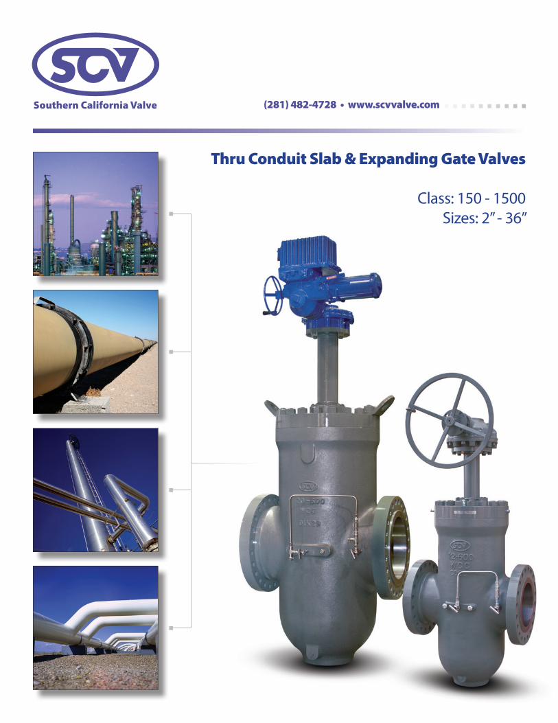
Thru Conduit Slab & Expanding Gate Valves
Class: 150 - 1500Sizes: 2” - 36”

SOUTHERN CALIFORNIA VALVE manufactures some of the most
dependable cast steel Thru Conduit Slab and Expanding Gate Valves in the
industry. Both designs utilize flanged and butt-weld end connections, and
are manufactured and tested in accordance with API 6D. The full port
bi-directional flow capability minimizes pressure drop and turbulence.
The SCV design offers many features and options beneficial for oil, gas,
and liquid applications making it the most demanded Thru Conduit Gate
on the market.
Innovative valve solutions.®
SCV Thru Conduit Slab & Expanding Gate Valves
[ Product Preview ]
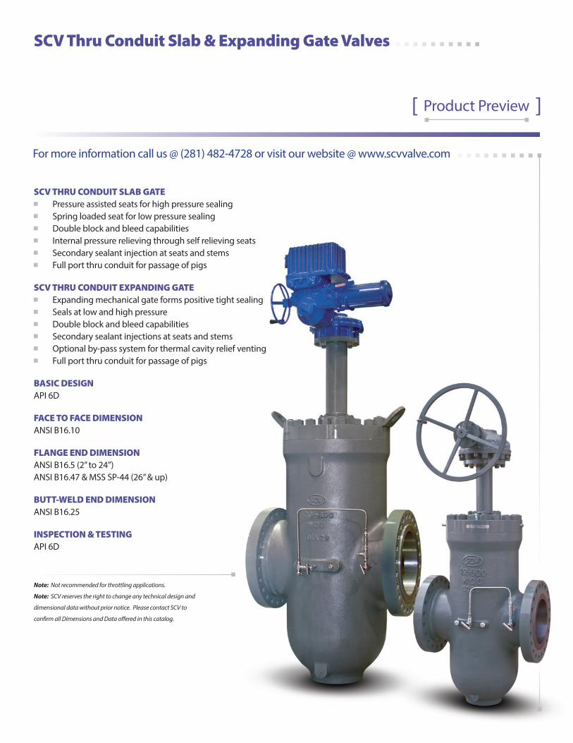
SCV THRU CONDUIT SLAB GATE Pressure assisted seats for high pressure sealing Spring loaded seat for low pressure sealing Double block and bleed capabilities Internal pressure relieving through self relieving seats Secondary sealant injection at seats and stems Full port thru conduit for passage of pigs
SCV THRU CONDUIT EXPANDING GATE Expanding mechanical gate forms positive tight sealing Seals at low and high pressure Double block and bleed capabilities Secondary sealant injections at seats and stems Optional by-pass system for thermal cavity relief venting Full port thru conduit for passage of pigs
BASIC DESIGN API 6D
FACE TO FACE DIMENSION ANSI B16.10
FLANGE END DIMENSION ANSI B16.5 (2” to 24”) ANSI B16.47 & MSS SP-44 (26” & up)
BUTT-WELD END DIMENSION ANSI B16.25
INSPECTION & TESTING API 6D
Note: Not recommended for throttling applications.
Note: SCV reserves the right to change any technical design and
dimensional data without prior notice. Please contact SCV to
confirm all Dimensions and Data offered in this catalog.
For more information call us @ (281) 482-4728 or visit our website @ www.scvvalve.com
Southern California Valve’s product lines include commodity valves as well as specialty valves in all Sizes, Pressure Classes & Metallurgy; including Carbon Steel, Stainless Steel & Exotic Alloys. The valve types include Gate, Globe, Swing Check - Bolted Bonnet & Pressure Seal Bonnet, Ball - floating, trunnion, rising stem, Thru-Conduit Gate - slab and expanding, Swing Check - Full and Regular Port, Lubricated Plugs, Dual Plate Checks - wafer and lug. Southern California Valve’s High Quality Standards demand 100% pressure testing of every valve to insure its reliability and full customer satisfaction.
At Southern California Valve, we pride ourselves with high quality products in the commodity and specialty valve lines, as well as, timely deliveries, and competitive prices.
Company History Southern California Valve was established in 1972. The primary focus of the Company was to provide full inline field service for valve maintenance as well as in house valve modifications. While serving the Power Industry, Paper & Pulp, Oil & Gas, and the Petro Chemical Industry; through years of dedication and commitment to quality and service, Southern California Valve has become one of the largest West Coast full range, field service companies, with a reputation for superior quality.
In the mid 1970s, Southern California Valve entered the valve manufacturing industry, primarily serving the Power Industry. Since that time, Southern California Valve has expanded their products to cover a broad range of valves. Southern California Valve holds the API 6A & API 6D Monogram, API Q1 Quality Management System, and ASME “R” stamp. The Corporate office and manufacturing facility is located in Santa Fe Springs, California. The Sales and Projects office is located in Santa Fe, Texas.
Mission Statement Southern California Valve is committed to consistently providing products that meet or exceed customer and regulatory specifications. SCV aims to enhance customer satisfaction through implementing the highest levels of quality standards while assuring full conformity to those requirements.
Page
Table of Contents ...............................................................................................................................................................................................................................1
Complete Product Line ...................................................................................................................................................................................................................2
Certifications .......................................................................................................................................................................................................................................3
• American Petroleum Institute (API)
• ISO 9001:2008
• Canadian Registration Numbers
• CE PED
Figure Number Chart ............................................................................................................................................................................................................... 4 & 5
Valve ID Tag & Valve Markings Identification .........................................................................................................................................................................6
Thru ConduiT Slab & Expanding gaTE ValVES ...................................................................................................................7Thru Conduit Slab Gate Expanded View & Bill of Materials ..............................................................................................................................................8
Slab Gate Advanced Mechanical Details .................................................................................................................................................................................9
Thru Conduit Expanding Gate Expanded View & Bill of Materials ............................................................................................................................. 10
Expanding Gate Advanced Mechanical Details ................................................................................................................................................................. 11
Slab Gate Valve Dimensions 150 Class ................................................................................................................................................................................... 12
Slab Gate Valve Dimensions 300 Class ................................................................................................................................................................................... 13
Slab & Expanding Gate Valve Dimensions 600 Class ....................................................................................................................................................... 14
Slab & Expanding Gate Valve Dimensions 900 Class ....................................................................................................................................................... 15
Cv Values ............................................................................................................................................................................................................................................ 16
Optional Thermal Relief Modifications .................................................................................................................................................................................. 16
Pressure Temperature Ratings ................................................................................................................................................................................17, 18, & 19
Flange Dimensions .............................................................................................................................................................................................................. 20 & 21
Butt-welding Dimensions ................................................................................................................................................................................................. 24 & 25
Industry Standards for Valve Manufacturing ...................................................................................................................................................................... 26
Terms and Conditions ................................................................................................................................................................................................................... 27
Table of Contents
2
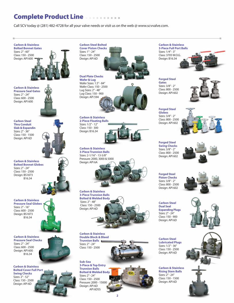
Forged SteelglobesSizes: 3/8” - 2”Class: 800 - 2500Design: API 602
Carbon & Stainless pressure Seal gatesSizes: 2” - 24”Class: 600 - 2500Design: API 600
Carbon Steel Thru ConduitSlab & Expanding gatesSizes: 2” - 36”Class: 150 - 1500Design: API 6D
Carbon & Stainless bolted bonnet globesSizes: 2” - 24”Class: 150 - 2500Design: BS1873 B16.34
Carbon & Stainless pressure Seal globesSizes: 2” - 16”Class: 600 - 2500Design: BS1873 B16.34
Carbon & Stainless pressure Seal ChecksSizes: 2” - 24”Class: 600 - 2500Design: API 600 B16.34
Carbon Steellubricated plugsSizes: 1/2” - 36”Class: 150 - 2500Design: API 6D
Forged SteelSwing ChecksSizes: 3/8” - 2”Class: 800 - 2500Design: API 602
Forged Steelpiston ChecksSizes: 3/8” - 2”Class: 800 - 2500Design: API 602
Carbon & Stainless bolted bonnet gatesSizes: 2” - 60”Class: 150 - 2500Design: API 600
Carbon Steel bolted Cover piston ChecksSizes: 1” - 24”Class: 150 - 2500Design: API 6D
Carbon & Stainless2-piece Floating ballsSizes: 1/2” - 12”Class: 150 - 300Design: B16.34
Complete Product Line Call SCV today @ (281) 482-4728 for all your valve needs or visit us on the web @ www.scvvalve.com.
Carbon & Stainless3-piece Trunnion ballsbolted & Welded body Sizes: 2” - 48” Class: 150 - 2500Design: API 6D
Forged SteelgatesSizes: 3/8” - 2”Class: 800 - 2500Design: API 602
Carbon & Stainless3-piece Full port ballsSizes: 1/4” - 3”Class: 3705 W.O.G.Design: B16.34
Carbon Steeldual SealExpanding plugsSizes: 2” - 24”Class: 150 - 900Design: API 6D
Carbon & Stainlessdouble block & bleedTrunnion ballsSizes: 2” - 24”Class: 150 - 2500
Sub-Sea3-piece & Top EntryTrunnion ballsbolted & Welded bodySizes: 2” - 24”Class: 150 - 2500Pressure: 2000 - 15000Design: API 6D API 6DSS
Carbon & Stainlessrising Stem ballsSizes: 2” - 24”Class: 150 - 1500Design: API 6D
dual plate Checks Wafer & lugWafer Sizes: 1.5” - 84”Wafer Class: 150 - 2500Lug Sizes: 2” - 48”Lug Class: 150 - 900Design: API 594
Carbon & Stainlessbolted Cover Full portSwing ChecksSizes: 2” - 52”Class: 150 - 2500Design: API 6D
Carbon & Stainless3-piece Trunnion ballsSizes: 2-1/16” - 13-5/8”Pressure: 2000, 3000 & 5000Design: API 6A
3
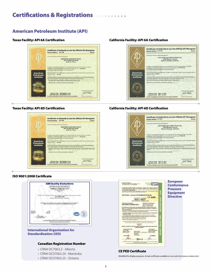
American Petroleum Institute (API)
Texas Facility: API 6A Certification California Facility: API 6A Certification
Texas Facility: API 6D Certification California Facility: API 6D Certification
Canadian Registration Number
• CRN# OC7063.2 - Alberta• CRN# OC07063.24 - Manitoba• CRN# OC07063.25 - Ontario
Certifications & Registrations
International Organization for Standardization (ISO)
EuropeanConformance Pressure EquipmentDirective
ISO 9001:2008 Certificate
CE PED Certificate(Modified for display purposes. Actual certificates available on our web site (www.scvvalve.com).
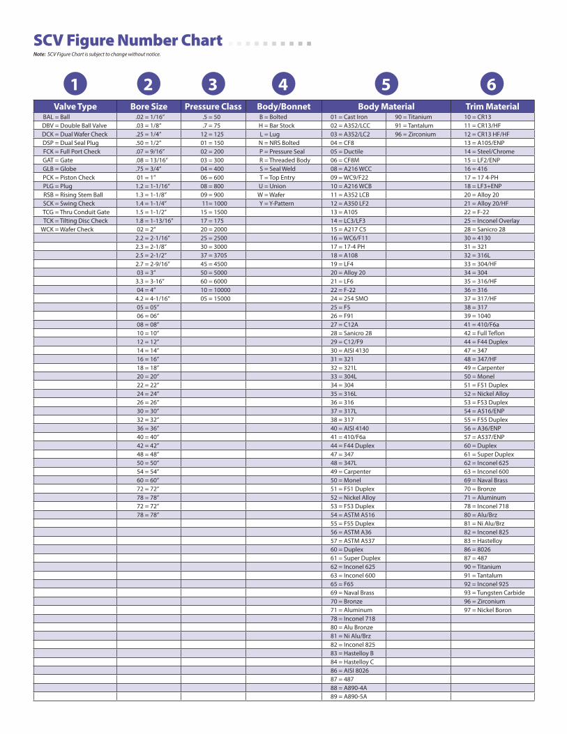
SCV Figure Number Chart
Valve Type bore Size pressure Class body/bonnet body Material Trim MaterialBAL = Ball .02 = 1/16” .5 = 50 B = Bolted 01 = Cast Iron 90 = Titanium 10 = CR13DBV = Double Ball Valve .03 = 1/8” .7 = 75 H = Bar Stock 02 = A352/LCC 91 = Tantalum 11 = CR13/HFDCK = Dual Wafer Check .25 = 1/4” 12 = 125 L = Lug 03 = A352/LC2 96 = Zirconium 12 = CR13 HF/HFDSP = Dual Seal Plug .50 = 1/2” 01 = 150 N = NRS Bolted 04 = CF8 13 = A105/ENPFCK = Full Port Check .07 = 9/16” 02 = 200 P = Pressure Seal 05 = Ductile 14 = Steel/ChromeGAT = Gate .08 = 13/16” 03 = 300 R = Threaded Body 06 = CF8M 15 = LF2/ENPGLB = Globe .75 = 3/4” 04 = 400 S = Seal Weld 08 = A216 WCC 16 = 416PCK = Piston Check 01 = 1” 06 = 600 T = Top Entry 09 = WC9/F22 17 = 17 4-PHPLG = Plug 1.2 = 1-1/16” 08 = 800 U = Union 10 = A216 WCB 18 = LF3+ENPRSB = Rising Stem Ball 1.3 = 1-1/8” 09 = 900 W = Wafer 11 = A352 LCB 20 = Alloy 20SCK = Swing Check 1.4 = 1-1/4” 11= 1000 Y = Y-Pattern 12 = A350 LF2 21 = Alloy 20/HFTCG = Thru Conduit Gate 1.5 = 1-1/2” 15 = 1500 13 = A105 22 = F-22TCK = Tilting Disc Check 1.8 = 1-13/16” 17 = 175 14 = LC3/LF3 25 = Inconel Overlay
WCK = Wafer Check 02 = 2” 20 = 2000 15 = A217 C5 28 = Sanicro 282.2 = 2-1/16” 25 = 2500 16 = WC6/F11 30 = 41302.3 = 2-1/8” 30 = 3000 17 = 17-4 PH 31 = 3212.5 = 2-1/2” 37 = 3705 18 = A108 32 = 316L2.7 = 2-9/16” 45 = 4500 19 = LF4 33 = 304/HF 03 = 3” 50 = 5000 20 = Alloy 20 34 = 3043.3 = 3-16” 60 = 6000 21 = LF6 35 = 316/HF 04 = 4” 10 = 10000 22 = F-22 36 = 3164.2 = 4-1/16” 05 = 15000 24 = 254 SMO 37 = 317/HF 05 = 05” 25 = F5 38 = 317 06 = 06” 26 = F91 39 = 1040 08 = 08” 27 = C12A 41 = 410/F6a 10 = 10” 28 = Sanicro 28 42 = Full Teflon 12 = 12” 29 = C12/F9 44 = F44 Duplex 14 = 14” 30 = AISI 4130 47 = 347 16 = 16” 31 = 321 48 = 347/HF 18 = 18” 32 = 321L 49 = Carpenter 20 = 20” 33 = 304L 50 = Monel 22 = 22” 34 = 304 51 = F51 Duplex 24 = 24” 35 = 316L 52 = Nickel Alloy 26 = 26” 36 = 316 53 = F53 Duplex 30 = 30” 37 = 317L 54 = A516/ENP 32 = 32” 38 = 317 55 = F55 Duplex 36 = 36” 40 = AISI 4140 56 = A36/ENP 40 = 40” 41 = 410/F6a 57 = A537/ENP 42 = 42” 44 = F44 Duplex 60 = Duplex 48 = 48” 47 = 347 61 = Super Duplex 50 = 50” 48 = 347L 62 = Inconel 625 54 = 54” 49 = Carpenter 63 = Inconel 600 60 = 60” 50 = Monel 69 = Naval Brass 72 = 72” 51 = F51 Duplex 70 = Bronze 78 = 78” 52 = Nickel Alloy 71 = Aluminum 72 = 72” 53 = F53 Duplex 78 = Inconel 718 78 = 78” 54 = ASTM A516 80 = Alu/Brz
55 = F55 Duplex 81 = Ni Alu/Brz56 = ASTM A36 82 = Inconel 82557 = ASTM A537 83 = Hastelloy60 = Duplex 86 = 802661 = Super Duplex 87 = 48762 = Inconel 625 90 = Titanium63 = Inconel 600 91 = Tantalum65 = F65 92 = Inconel 92569 = Naval Brass 93 = Tungsten Carbide70 = Bronze 96 = Zirconium71 = Aluminum 97 = Nickel Boron78 = Inconel 71880 = Alu Bronze81 = Ni Alu/Brz82 = Inconel 82583 = Hastelloy B84 = Hastelloy C86 = AISI 802687 = 48788 = A890-4A89 = A890-5A
Note: SCV Figure Chart is subject to change without notice.
1 2 3 4 5 6
5
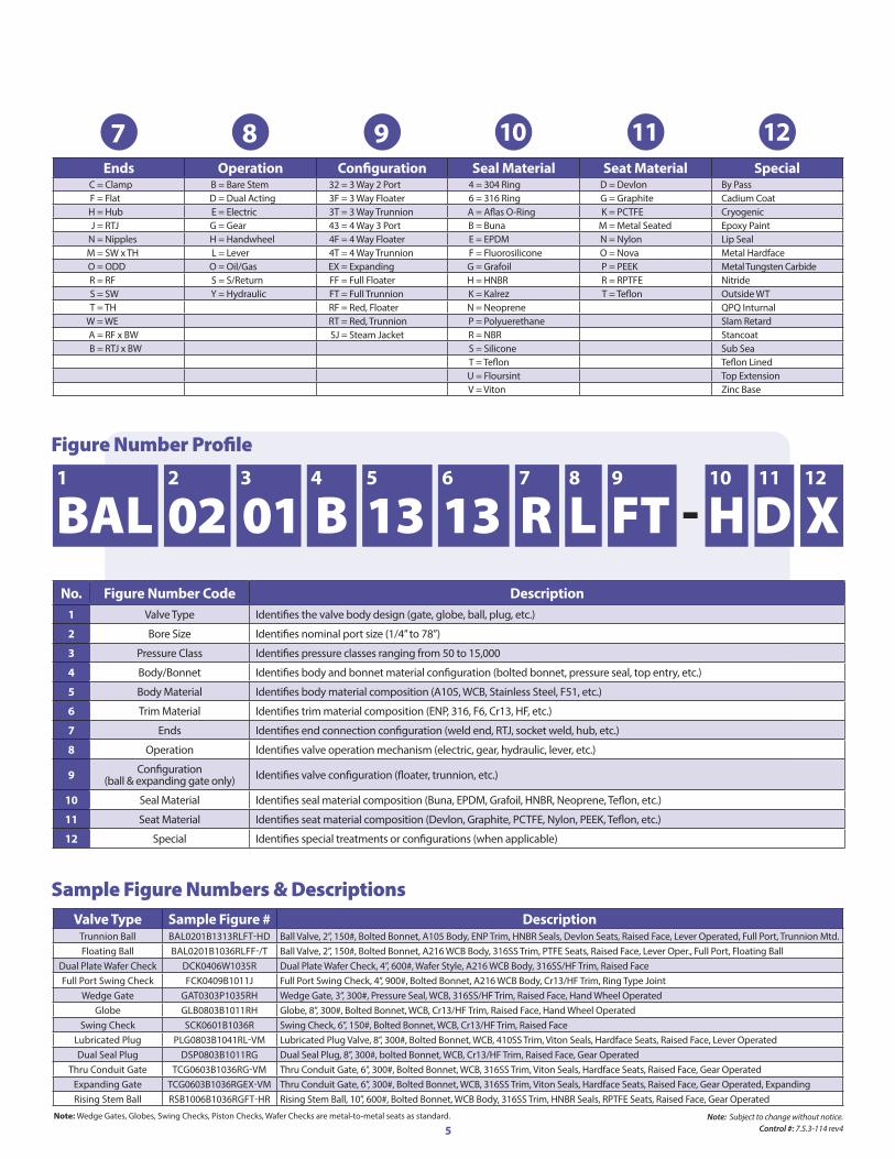
5 6 9 10 11 12 4 7 8 2 1 3
Ends operation Configuration Seal Material Seat Material SpecialC = Clamp B = Bare Stem 32 = 3 Way 2 Port 4 = 304 Ring D = Devlon By PassF = Flat D = Dual Acting 3F = 3 Way Floater 6 = 316 Ring G = Graphite Cadium CoatH = Hub E = Electric 3T = 3 Way Trunnion A = Aflas O-Ring K = PCTFE CryogenicJ = RTJ G = Gear 43 = 4 Way 3 Port B = Buna M = Metal Seated Epoxy Paint
N = Nipples H = Handwheel 4F = 4 Way Floater E = EPDM N = Nylon Lip SealM = SW x TH L = Lever 4T = 4 Way Trunnion F = Fluorosilicone O = Nova Metal HardfaceO = ODD O = Oil/Gas EX = Expanding G = Grafoil P = PEEK Metal Tungsten CarbideR = RF S = S/Return FF = Full Floater H = HNBR R = RPTFE NitrideS = SW Y = Hydraulic FT = Full Trunnion K = Kalrez T = Teflon Outside WTT = TH RF = Red, Floater N = Neoprene QPQ Inturnal
W = WE RT = Red, Trunnion P = Polyuerethane Slam RetardA = RF x BW SJ = Steam Jacket R = NBR StancoatB = RTJ x BW S = Silicone Sub Sea
T = Teflon Teflon LinedU = Floursint Top ExtensionV = Viton Zinc Base
Sample Figure Numbers & DescriptionsValve Type Sample Figure # description
Trunnion Ball BAL0201B1313RLFT-HD Ball Valve, 2”, 150#, Bolted Bonnet, A105 Body, ENP Trim, HNBR Seals, Devlon Seats, Raised Face, Lever Operated, Full Port, Trunnion Mtd.Floating Ball BAL0201B1036RLFF-/T Ball Valve, 2”, 150#, Bolted Bonnet, A216 WCB Body, 316SS Trim, PTFE Seats, Raised Face, Lever Oper., Full Port, Floating Ball
Dual Plate Wafer Check DCK0406W1035R Dual Plate Wafer Check, 4”, 600#, Wafer Style, A216 WCB Body, 316SS/HF Trim, Raised FaceFull Port Swing Check FCK0409B1011J Full Port Swing Check, 4”, 900#, Bolted Bonnet, A216 WCB Body, Cr13/HF Trim, Ring Type Joint
Wedge Gate GAT0303P1035RH Wedge Gate, 3”, 300#, Pressure Seal, WCB, 316SS/HF Trim, Raised Face, Hand Wheel OperatedGlobe GLB0803B1011RH Globe, 8”, 300#, Bolted Bonnet, WCB, Cr13/HF Trim, Raised Face, Hand Wheel Operated
Swing Check SCK0601B1036R Swing Check, 6”, 150#, Bolted Bonnet, WCB, Cr13/HF Trim, Raised FaceLubricated Plug PLG0803B1041RL-VM Lubricated Plug Valve, 8”, 300#, Bolted Bonnet, WCB, 410SS Trim, Viton Seals, Hardface Seats, Raised Face, Lever OperatedDual Seal Plug DSP0803B1011RG Dual Seal Plug, 8”, 300#, bolted Bonnet, WCB, Cr13/HF Trim, Raised Face, Gear Operated
Thru Conduit Gate TCG0603B1036RG-VM Thru Conduit Gate, 6”, 300#, Bolted Bonnet, WCB, 316SS Trim, Viton Seals, Hardface Seats, Raised Face, Gear OperatedExpanding Gate TCG0603B1036RGEX-VM Thru Conduit Gate, 6”, 300#, Bolted Bonnet, WCB, 316SS Trim, Viton Seals, Hardface Seats, Raised Face, Gear Operated, ExpandingRising Stem Ball RSB1006B1036RGFT-HR Rising Stem Ball, 10”, 600#, Bolted Bonnet, WCB Body, 316SS Trim, HNBR Seals, RPTFE Seats, Raised Face, Gear Operated
BAL 02 01 B 13 13 R L FT - H D XFigure Number Profile
no. Figure number Code description1 Valve Type Identifies the valve body design (gate, globe, ball, plug, etc.)
2 Bore Size Identifies nominal port size (1/4” to 78”)
3 Pressure Class Identifies pressure classes ranging from 50 to 15,000
4 Body/Bonnet Identifies body and bonnet material configuration (bolted bonnet, pressure seal, top entry, etc.)
5 Body Material Identifies body material composition (A105, WCB, Stainless Steel, F51, etc.)
6 Trim Material Identifies trim material composition (ENP, 316, F6, Cr13, HF, etc.)
7 Ends Identifies end connection configuration (weld end, RTJ, socket weld, hub, etc.)
8 Operation Identifies valve operation mechanism (electric, gear, hydraulic, lever, etc.)
9 Configuration(ball & expanding gate only) Identifies valve configuration (floater, trunnion, etc.)
10 Seal Material Identifies seal material composition (Buna, EPDM, Grafoil, HNBR, Neoprene, Teflon, etc.)
11 Seat Material Identifies seat material composition (Devlon, Graphite, PCTFE, Nylon, PEEK, Teflon, etc.)
12 Special Identifies special treatments or configurations (when applicable)
note: Wedge Gates, Globes, Swing Checks, Piston Checks, Wafer Checks are metal-to-metal seats as standard.
7 8 9 10 11 12
Note: Subject to change without notice.Control #: 7.5.3-114 rev4
6note: SCV reserves the right to modify our products for improvement without prior notice.
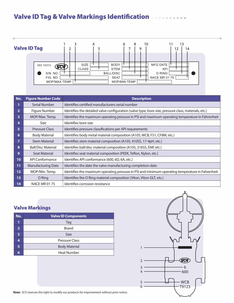
Valve ID Tag & Valve Markings Identification
1 32
45
67
89
10 1112
1314
no. Figure number Code description
1 Serial Number Identifies certified manufacturers serial number
2 Figure Number Identifies the detailed valve configuration (valve type, bore size, pressure class, materials, etc.)
3 MOP/Max. Temp. Identifies the maximum operating pressure in PSI and maximum operating temperature in Fahrenheit
4 Size Identifies bore size
5 Pressure Class Identifies pressure classifications per API requirements
6 Body Material Identifies body metal material composition (A105, WCB, F51, CF8M, etc.)
7 Stem Material Identifies stem material composition (A105, 410SS, 17-4pH, etc.)
8 Ball/Disc Material Identifies ball/disc material composition (A105, 316SS, ENP, etc.)
9 Seat Material Identifies seat material composition (PEEK, Teflon, Nylon, etc.)
10 API Conformance Identifies API conformance (600, 6D, 6A, etc.)
11 Manufacturing Date Identifies the date the valve manufacturing completion date
12 MOP/Min. Temp. Identifies the maximum operating pressure in PSI and minimum operating temperature in Fahrenheit
13 O Ring Identifies the O Ring material composition (Viton, Viton GLT, etc.)
14 NACE MR 01 75 Identifies corrosion resistance
no. Valve id Components
1 Tag
2 Brand
3 Size
4 Pressure Class
5 Body Material
6 Heat Number
Valve Markings
Valve ID Tag
6600
WCBT9123
3
2
1
4
56
7
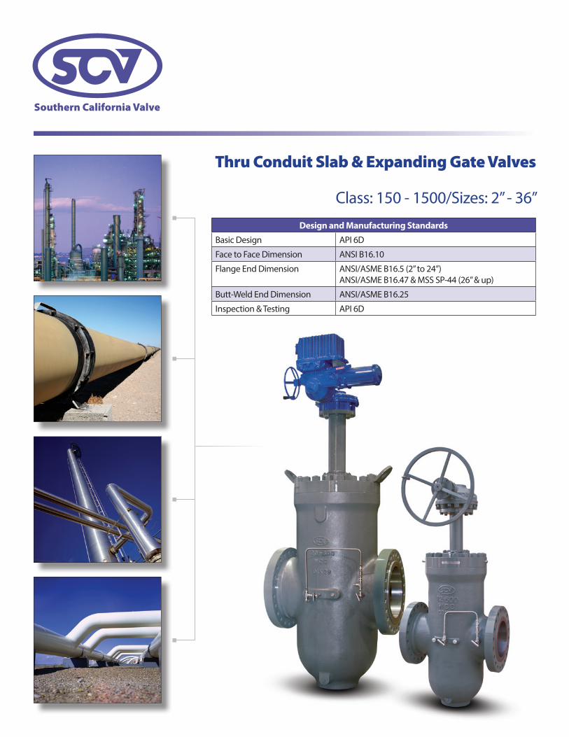
Thru Conduit Slab & Expanding Gate Valves
Class: 150 - 1500/Sizes: 2” - 36”
design and Manufacturing Standards
Basic Design API 6D
Face to Face Dimension ANSI B16.10
Flange End Dimension ANSI/ASME B16.5 (2” to 24”)ANSI/ASME B16.47 & MSS SP-44 (26” & up)
Butt-Weld End Dimension ANSI/ASME B16.25
Inspection & Testing API 6D
8
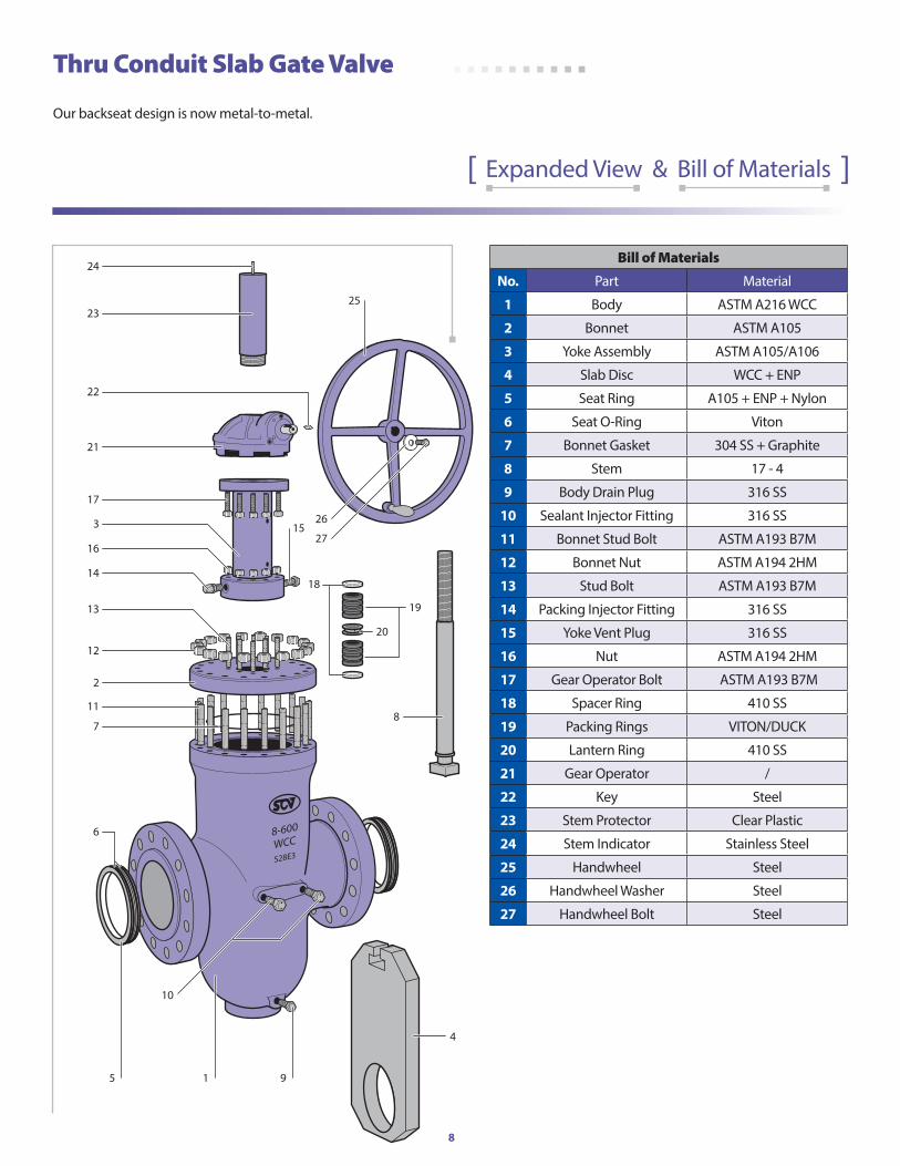
Thru Conduit Slab Gate Valve
Our backseat design is now metal-to-metal.
[ Expanded View & Bill of Materials ]
4
19
20
18
23
24
8
2
11
7
10
14
16
3
21
17
22
25
15
915
13
12
26
27
6
Bill of Materials
no. Part Material
1 Body ASTM A216 WCC
2 Bonnet ASTM A105
3 Yoke Assembly ASTM A105/A106
4 Slab Disc WCC + ENP
5 Seat Ring A105 + ENP + Nylon
6 Seat O-Ring Viton
7 Bonnet Gasket 304 SS + Graphite
8 Stem 17 - 4
9 Body Drain Plug 316 SS
10 Sealant Injector Fitting 316 SS
11 Bonnet Stud Bolt ASTM A193 B7M
12 Bonnet Nut ASTM A194 2HM
13 Stud Bolt ASTM A193 B7M
14 Packing Injector Fitting 316 SS
15 Yoke Vent Plug 316 SS
16 Nut ASTM A194 2HM
17 Gear Operator Bolt ASTM A193 B7M
18 Spacer Ring 410 SS
19 Packing Rings VITON/DUCK
20 Lantern Ring 410 SS
21 Gear Operator /
22 Key Steel
23 Stem Protector Clear Plastic
24 Stem Indicator Stainless Steel
25 Handwheel Steel
26 Handwheel Washer Steel
27 Handwheel Bolt Steel
9
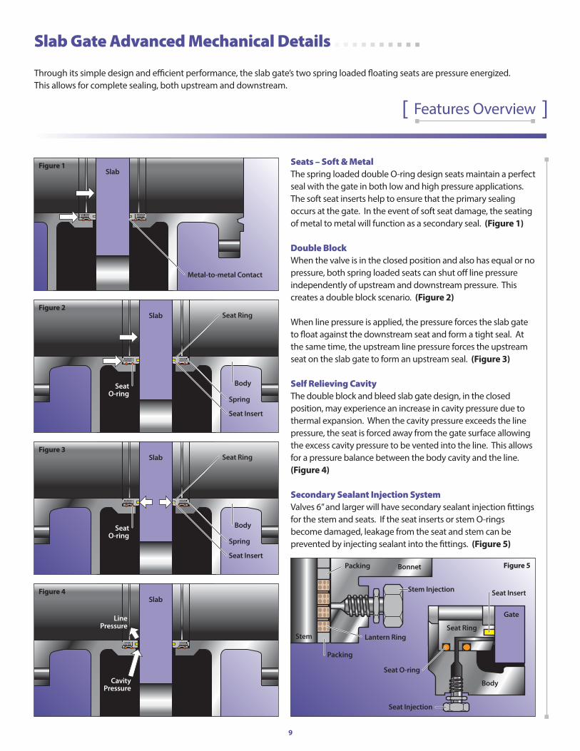
Seats – Soft & MetalThe spring loaded double O-ring design seats maintain a perfect seal with the gate in both low and high pressure applications. The soft seat inserts help to ensure that the primary sealing occurs at the gate. In the event of soft seat damage, the seating of metal to metal will function as a secondary seal. (Figure 1)
Double BlockWhen the valve is in the closed position and also has equal or no pressure, both spring loaded seats can shut off line pressure independently of upstream and downstream pressure. This creates a double block scenario. (Figure 2)
When line pressure is applied, the pressure forces the slab gate to float against the downstream seat and form a tight seal. At the same time, the upstream line pressure forces the upstream seat on the slab gate to form an upstream seal. (Figure 3)
Self Relieving CavityThe double block and bleed slab gate design, in the closed position, may experience an increase in cavity pressure due to thermal expansion. When the cavity pressure exceeds the line pressure, the seat is forced away from the gate surface allowing the excess cavity pressure to be vented into the line. This allows for a pressure balance between the body cavity and the line. (Figure 4)
Secondary Sealant Injection SystemValves 6” and larger will have secondary sealant injection fittings for the stem and seats. If the seat inserts or stem O-rings become damaged, leakage from the seat and stem can be prevented by injecting sealant into the fittings. (Figure 5)
Slab Gate Advanced Mechanical Details
Through its simple design and efficient performance, the slab gate’s two spring loaded floating seats are pressure energized. This allows for complete sealing, both upstream and downstream.
[ Features Overview ]
CavityPressure
LinePressure
Slab
Body
Seat Injection
Seat O-ring
Seat Insert
Seat Ring
Gate
Stem
Stem Injection
Packing
Lantern Ring
Packing Bonnet
Metal-to-metal Contact
Slab
Spring
Body
Seat Insert
Seat RingSlab
SeatO-ring
Spring
Body
Seat Insert
Seat RingSlab
SeatO-ring
Figure 1
Figure 2
Figure 3
Figure 4
Figure 5
Bill of Materials
no. Part Material
1 Body ASTM A216 WCC
2 Bonnet ASTM A105
3 Yoke Assembly ASTM A105/A106
4 Slab Disc WCC + ENP
5 Seat Ring A105 + ENP + Nylon
6 Seat O-Ring Viton
7 Bonnet Gasket 304 SS + Graphite
8 Stem 17 - 4
9 Body Drain Plug 316 SS
10 Sealant Injector Fitting 316 SS
11 Bonnet Stud Bolt ASTM A193 B7M
12 Bonnet Nut ASTM A194 2HM
13 Stud Bolt ASTM A193 B7M
14 Packing Injector Fitting 316 SS
15 Yoke Vent Plug 316 SS
16 Nut ASTM A194 2HM
17 Gear Operator Bolt ASTM A193 B7M
18 Spacer Ring 410 SS
19 Packing Rings VITON/DUCK
20 Lantern Ring 410 SS
21 Gear Operator /
22 Key Steel
23 Stem Protector Clear Plastic
24 Stem Indicator Stainless Steel
25 Handwheel Steel
26 Handwheel Washer Steel
27 Handwheel Bolt Steel
10
23
24
22
27
28
11
2
15
10
13
9
14
18
20
3
25
21
26
29
19
8 7 121
5
4
6
17
16
30
31
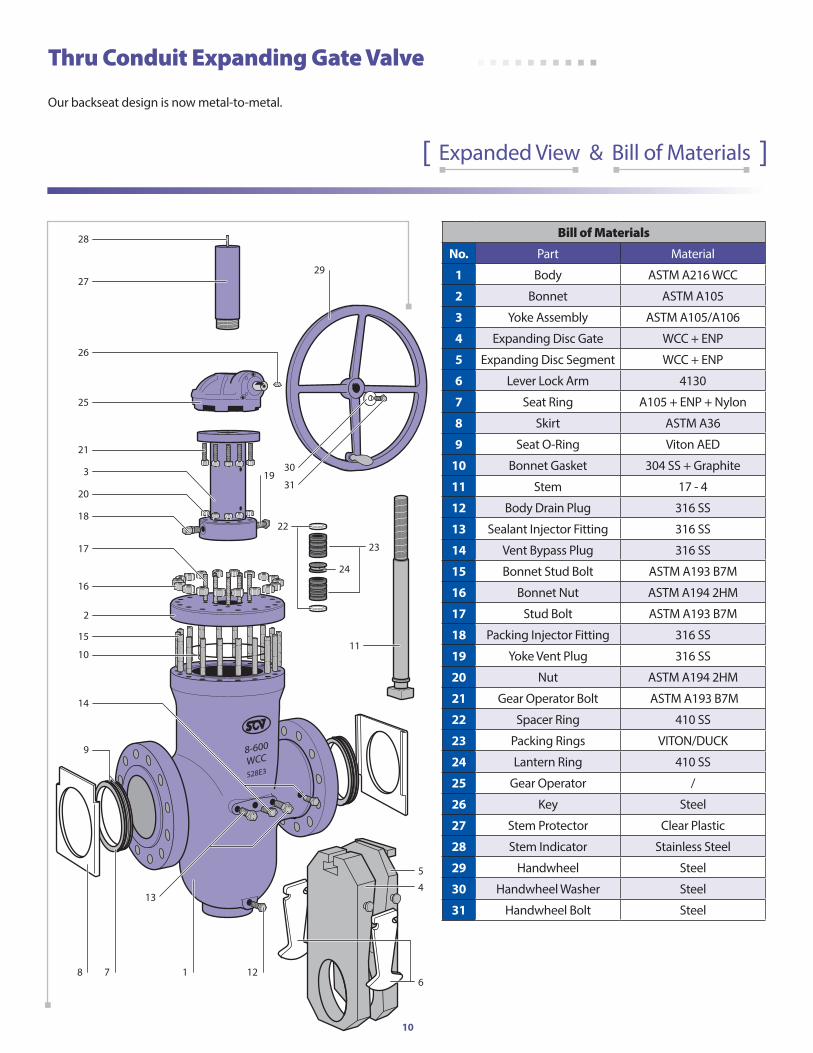
Thru Conduit Expanding Gate Valve
Our backseat design is now metal-to-metal.
[ Expanded View & Bill of Materials ]
Bill of Materials
no. Part Material
1 Body ASTM A216 WCC
2 Bonnet ASTM A105
3 Yoke Assembly ASTM A105/A106
4 Expanding Disc Gate WCC + ENP
5 Expanding Disc Segment WCC + ENP
6 Lever Lock Arm 4130
7 Seat Ring A105 + ENP + Nylon
8 Skirt ASTM A36
9 Seat O-Ring Viton AED
10 Bonnet Gasket 304 SS + Graphite
11 Stem 17 - 4
12 Body Drain Plug 316 SS
13 Sealant Injector Fitting 316 SS
14 Vent Bypass Plug 316 SS
15 Bonnet Stud Bolt ASTM A193 B7M
16 Bonnet Nut ASTM A194 2HM
17 Stud Bolt ASTM A193 B7M
18 Packing Injector Fitting 316 SS
19 Yoke Vent Plug 316 SS
20 Nut ASTM A194 2HM
21 Gear Operator Bolt ASTM A193 B7M
22 Spacer Ring 410 SS
23 Packing Rings VITON/DUCK
24 Lantern Ring 410 SS
25 Gear Operator /
26 Key Steel
27 Stem Protector Clear Plastic
28 Stem Indicator Stainless Steel
29 Handwheel Steel
30 Handwheel Washer Steel
31 Handwheel Bolt Steel
11
Sealant Injector
Fitting
Disc Gate Disc Segment
Disc SegmentStopSeat Rings
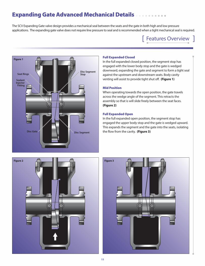
Full Expanded ClosedIn the full expanded closed position, the segment stop has engaged with the lower body stop and the gate is wedged downward, expanding the gate and segment to form a tight seal against the upstream and downstream seats. Body cavity venting will assist to provide tight shut off. (Figure 1)
Mid PositionWhen operating towards the open position, the gate travels across the wedge angle of the segment. This retracts the assembly so that is will slide freely between the seat faces. (Figure 2)
Full Expanded OpenIn the full expanded open position, the segment stop has engaged the upper body stop and the gate is wedged upward. This expands the segment and the gate into the seats, isolating the flow from the cavity. (Figure 3)
Expanding Gate Advanced Mechanical Details
The SCV Expanding Gate valve design provides a mechanical seal between the seats and the gate in both high and low pressure applications. The expanding gate valve does not require line pressure to seal and is recommended when a tight mechanical seal is required.
[ Features Overview ]
Figure 1
Figure 2 Figure 3
12
G1
G2
GW
L2L1
H1
H
L
H2
HW
CLA
SS 1
50
SiZEEnd-To-End CEnTEr-To-boTToM handWhEEl opEraTEd gEar opEraTEd WEighTS
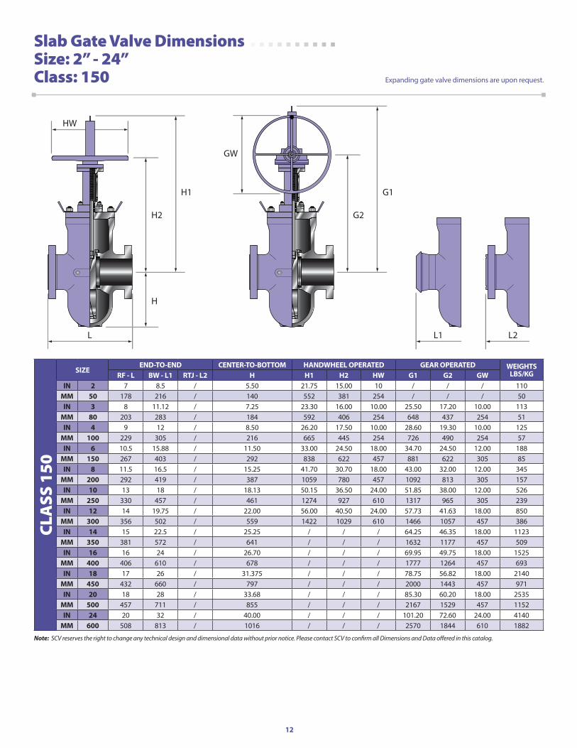
lbS/KgrF - l bW - l1 rTJ - l2 h h1 h2 hW g1 g2 gWin 2 7 8.5 / 5.50 21.75 15.00 10 / / / 110
MM 50 178 216 / 140 552 381 254 / / / 50in 3 8 11.12 / 7.25 23.30 16.00 10.00 25.50 17.20 10.00 113
MM 80 203 283 / 184 592 406 254 648 437 254 51in 4 9 12 / 8.50 26.20 17.50 10.00 28.60 19.30 10.00 125
MM 100 229 305 / 216 665 445 254 726 490 254 57in 6 10.5 15.88 / 11.50 33.00 24.50 18.00 34.70 24.50 12.00 188
MM 150 267 403 / 292 838 622 457 881 622 305 85in 8 11.5 16.5 / 15.25 41.70 30.70 18.00 43.00 32.00 12.00 345
MM 200 292 419 / 387 1059 780 457 1092 813 305 157in 10 13 18 / 18.13 50.15 36.50 24.00 51.85 38.00 12.00 526
MM 250 330 457 / 461 1274 927 610 1317 965 305 239in 12 14 19.75 / 22.00 56.00 40.50 24.00 57.73 41.63 18.00 850
MM 300 356 502 / 559 1422 1029 610 1466 1057 457 386in 14 15 22.5 / 25.25 / / / 64.25 46.35 18.00 1123
MM 350 381 572 / 641 / / / 1632 1177 457 509in 16 16 24 / 26.70 / / / 69.95 49.75 18.00 1525
MM 400 406 610 / 678 / / / 1777 1264 457 693in 18 17 26 / 31.375 / / / 78.75 56.82 18.00 2140
MM 450 432 660 / 797 / / / 2000 1443 457 971in 20 18 28 / 33.68 / / / 85.30 60.20 18.00 2535
MM 500 457 711 / 855 / / / 2167 1529 457 1152in 24 20 32 / 40.00 / / / 101.20 72.60 24.00 4140
MM 600 508 813 / 1016 / / / 2570 1844 610 1882
Slab Gate Valve Dimensions Size: 2” - 24”Class: 150 Expanding gate valve dimensions are upon request.
Note: SCV reserves the right to change any technical design and dimensional data without prior notice. Please contact SCV to confirm all Dimensions and Data offered in this catalog.
13
G1
G2
GW
L2L1
H1
H
L
H2
HW
CLA
SS 3
00
SiZEEnd-To-End CEnTEr-To-boTToM handWhEEl opEraTEd gEar opEraTEd WEighTS
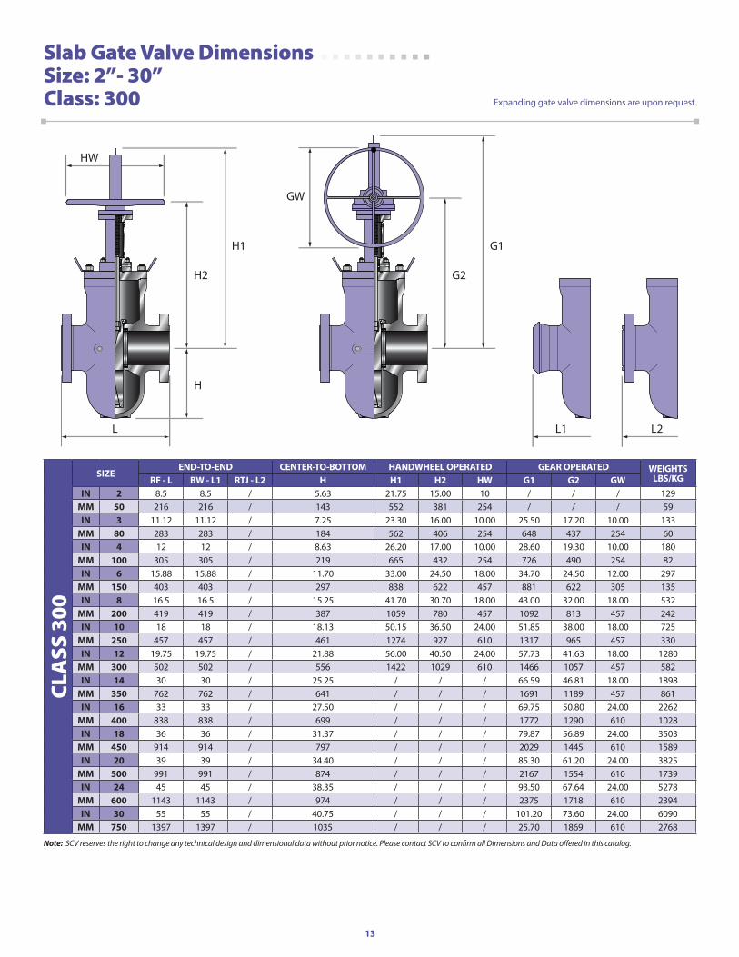
lbS/KgrF - l bW - l1 rTJ - l2 h h1 h2 hW g1 g2 gWin 2 8.5 8.5 / 5.63 21.75 15.00 10 / / / 129
MM 50 216 216 / 143 552 381 254 / / / 59in 3 11.12 11.12 / 7.25 23.30 16.00 10.00 25.50 17.20 10.00 133
MM 80 283 283 / 184 562 406 254 648 437 254 60in 4 12 12 / 8.63 26.20 17.00 10.00 28.60 19.30 10.00 180
MM 100 305 305 / 219 665 432 254 726 490 254 82in 6 15.88 15.88 / 11.70 33.00 24.50 18.00 34.70 24.50 12.00 297
MM 150 403 403 / 297 838 622 457 881 622 305 135in 8 16.5 16.5 / 15.25 41.70 30.70 18.00 43.00 32.00 18.00 532
MM 200 419 419 / 387 1059 780 457 1092 813 457 242in 10 18 18 / 18.13 50.15 36.50 24.00 51.85 38.00 18.00 725
MM 250 457 457 / 461 1274 927 610 1317 965 457 330in 12 19.75 19.75 / 21.88 56.00 40.50 24.00 57.73 41.63 18.00 1280
MM 300 502 502 / 556 1422 1029 610 1466 1057 457 582in 14 30 30 / 25.25 / / / 66.59 46.81 18.00 1898
MM 350 762 762 / 641 / / / 1691 1189 457 861in 16 33 33 / 27.50 / / / 69.75 50.80 24.00 2262
MM 400 838 838 / 699 / / / 1772 1290 610 1028in 18 36 36 / 31.37 / / / 79.87 56.89 24.00 3503
MM 450 914 914 / 797 / / / 2029 1445 610 1589in 20 39 39 / 34.40 / / / 85.30 61.20 24.00 3825
MM 500 991 991 / 874 / / / 2167 1554 610 1739in 24 45 45 / 38.35 / / / 93.50 67.64 24.00 5278
MM 600 1143 1143 / 974 / / / 2375 1718 610 2394in 30 55 55 / 40.75 / / / 101.20 73.60 24.00 6090
MM 750 1397 1397 / 1035 / / / 25.70 1869 610 2768
Slab Gate Valve Dimensions Size: 2”- 30”Class: 300 Expanding gate valve dimensions are upon request.
Note: SCV reserves the right to change any technical design and dimensional data without prior notice. Please contact SCV to confirm all Dimensions and Data offered in this catalog.
14
G1
G2
GW
L2L1
H1
H
L
H2
HW
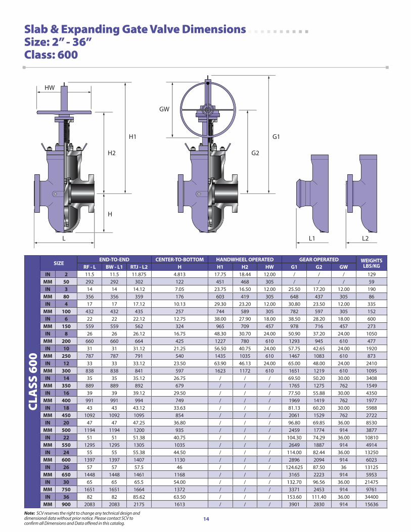
Slab & Expanding Gate Valve Dimensions Size: 2” - 36”Class: 600
CLA
SS 6
00
SiZEEnd-To-End CEnTEr-To-boTToM handWhEEl opEraTEd gEar opEraTEd WEighTS
lbS/KgrF - l bW - l1 rTJ - l2 h h1 h2 hW g1 g2 gWin 2 11.5 11.5 11.875 4.813 17.75 18.44 12.00 / / / 129
MM 50 292 292 302 122 451 468 305 / / / 59in 3 14 14 14.12 7.05 23.75 16.50 12.00 25.50 17.20 12.00 190
MM 80 356 356 359 176 603 419 305 648 437 305 86in 4 17 17 17.12 10.13 29.30 23.20 12.00 30.80 23.50 12.00 335
MM 100 432 432 435 257 744 589 305 782 597 305 152in 6 22 22 22.12 12.75 38.00 27.90 18.00 38.50 28.20 18.00 600
MM 150 559 559 562 324 965 709 457 978 716 457 273in 8 26 26 26.12 16.75 48.30 30.70 24.00 50.90 37.20 24.00 1050
MM 200 660 660 664 425 1227 780 610 1293 945 610 477in 10 31 31 31.12 21.25 56.50 40.75 24.00 57.75 42.65 24.00 1920
MM 250 787 787 791 540 1435 1035 610 1467 1083 610 873in 12 33 33 33.12 23.50 63.90 46.13 24.00 65.00 48.00 24.00 2410
MM 300 838 838 841 597 1623 1172 610 1651 1219 610 1095in 14 35 35 35.12 26.75 / / / 69.50 50.20 30.00 3408
MM 350 889 889 892 679 / / / 1765 1275 762 1549in 16 39 39 39.12 29.50 / / / 77.50 55.88 30.00 4350
MM 400 991 991 994 749 / / / 1969 1419 762 1977in 18 43 43 43.12 33.63 / / / 81.13 60.20 30.00 5988
MM 450 1092 1092 1095 854 / / / 2061 1529 762 2722in 20 47 47 47.25 36.80 / / / 96.80 69.85 36.00 8530
MM 500 1194 1194 1200 935 / / / 2459 1774 914 3877in 22 51 51 51.38 40.75 / / / 104.30 74.29 36.00 10810
MM 550 1295 1295 1305 1035 / / / 2649 1887 914 4914in 24 55 55 55.38 44.50 / / / 114.00 82.44 36.00 13250
MM 600 1397 1397 1407 1130 / / / 2896 2094 914 6023in 26 57 57 57.5 46 / / / 124.625 87.50 36 13125
MM 650 1448 1448 1461 1168 / / / 3165 2223 914 5953in 30 65 65 65.5 54.00 / / / 132.70 96.56 36.00 21475
MM 750 1651 1651 1664 1372 / / / 3371 2453 914 9761in 36 82 82 85.62 63.50 / / / 153.60 111.40 36.00 34400
MM 900 2083 2083 2175 1613 / / / 3901 2830 914 15636
Note: SCV reserves the right to change any technical design and dimensional data without prior notice. Please contact SCV to confirm all Dimensions and Data offered in this catalog.
15
G1
G2
GW
L2L1
H1
H
L
H2
HW
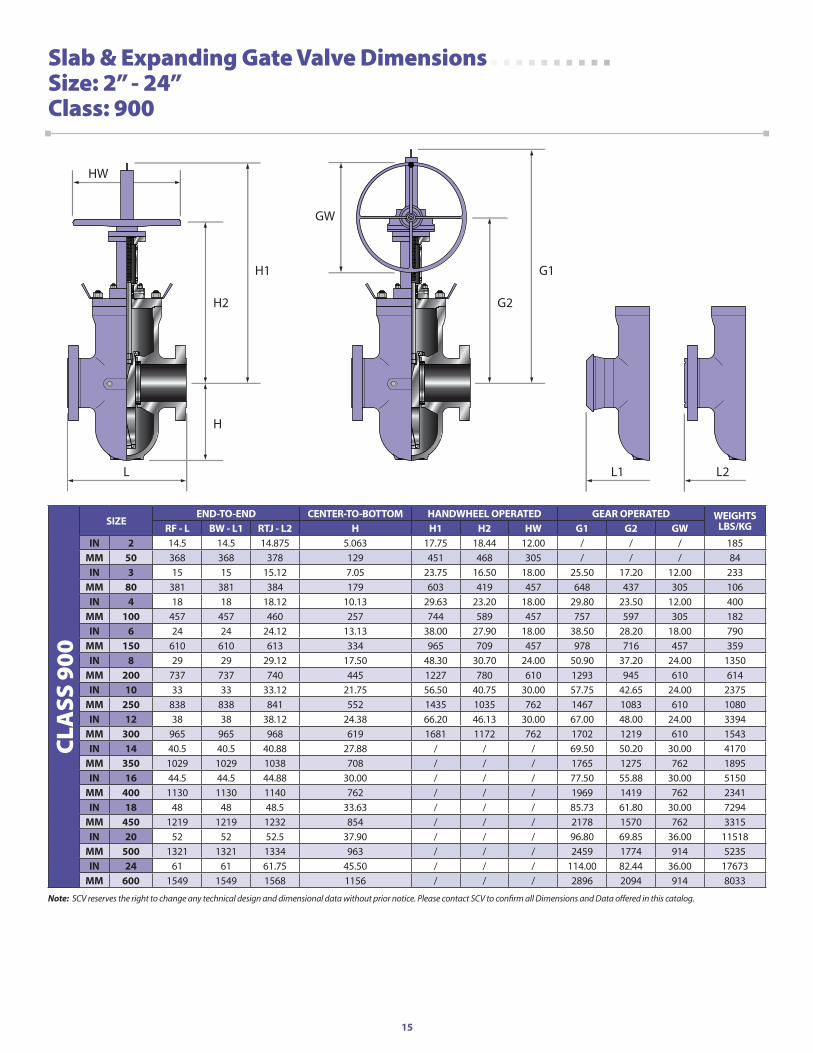
Slab & Expanding Gate Valve Dimensions Size: 2” - 24”Class: 900
CLA
SS 9
00
SiZEEnd-To-End CEnTEr-To-boTToM handWhEEl opEraTEd gEar opEraTEd WEighTS
lbS/KgrF - l bW - l1 rTJ - l2 h h1 h2 hW g1 g2 gWin 2 14.5 14.5 14.875 5.063 17.75 18.44 12.00 / / / 185
MM 50 368 368 378 129 451 468 305 / / / 84in 3 15 15 15.12 7.05 23.75 16.50 18.00 25.50 17.20 12.00 233
MM 80 381 381 384 179 603 419 457 648 437 305 106in 4 18 18 18.12 10.13 29.63 23.20 18.00 29.80 23.50 12.00 400
MM 100 457 457 460 257 744 589 457 757 597 305 182in 6 24 24 24.12 13.13 38.00 27.90 18.00 38.50 28.20 18.00 790
MM 150 610 610 613 334 965 709 457 978 716 457 359in 8 29 29 29.12 17.50 48.30 30.70 24.00 50.90 37.20 24.00 1350
MM 200 737 737 740 445 1227 780 610 1293 945 610 614in 10 33 33 33.12 21.75 56.50 40.75 30.00 57.75 42.65 24.00 2375
MM 250 838 838 841 552 1435 1035 762 1467 1083 610 1080in 12 38 38 38.12 24.38 66.20 46.13 30.00 67.00 48.00 24.00 3394
MM 300 965 965 968 619 1681 1172 762 1702 1219 610 1543in 14 40.5 40.5 40.88 27.88 / / / 69.50 50.20 30.00 4170
MM 350 1029 1029 1038 708 / / / 1765 1275 762 1895in 16 44.5 44.5 44.88 30.00 / / / 77.50 55.88 30.00 5150
MM 400 1130 1130 1140 762 / / / 1969 1419 762 2341in 18 48 48 48.5 33.63 / / / 85.73 61.80 30.00 7294
MM 450 1219 1219 1232 854 / / / 2178 1570 762 3315in 20 52 52 52.5 37.90 / / / 96.80 69.85 36.00 11518
MM 500 1321 1321 1334 963 / / / 2459 1774 914 5235in 24 61 61 61.75 45.50 / / / 114.00 82.44 36.00 17673
MM 600 1549 1549 1568 1156 / / / 2896 2094 914 8033
Note: SCV reserves the right to change any technical design and dimensional data without prior notice. Please contact SCV to confirm all Dimensions and Data offered in this catalog.
16
G1
G2
GW
L2L1
H1
H
L
H2
HW
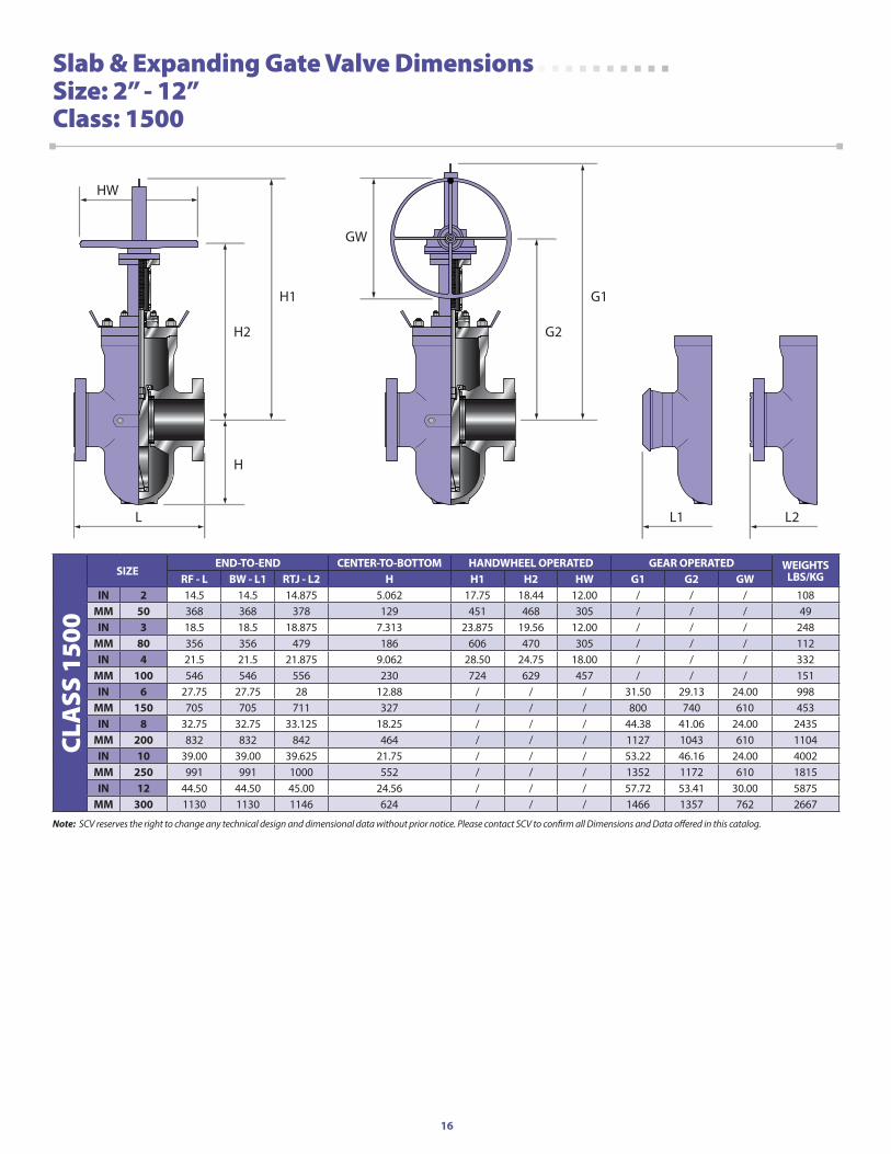
Slab & Expanding Gate Valve Dimensions Size: 2” - 12”Class: 1500
CLA
SS 1
500
SiZEEnd-To-End CEnTEr-To-boTToM handWhEEl opEraTEd gEar opEraTEd WEighTS
lbS/KgrF - l bW - l1 rTJ - l2 h h1 h2 hW g1 g2 gWin 2 14.5 14.5 14.875 5.062 17.75 18.44 12.00 / / / 108
MM 50 368 368 378 129 451 468 305 / / / 49in 3 18.5 18.5 18.875 7.313 23.875 19.56 12.00 / / / 248
MM 80 356 356 479 186 606 470 305 / / / 112in 4 21.5 21.5 21.875 9.062 28.50 24.75 18.00 / / / 332
MM 100 546 546 556 230 724 629 457 / / / 151in 6 27.75 27.75 28 12.88 / / / 31.50 29.13 24.00 998
MM 150 705 705 711 327 / / / 800 740 610 453in 8 32.75 32.75 33.125 18.25 / / / 44.38 41.06 24.00 2435
MM 200 832 832 842 464 / / / 1127 1043 610 1104in 10 39.00 39.00 39.625 21.75 / / / 53.22 46.16 24.00 4002
MM 250 991 991 1000 552 / / / 1352 1172 610 1815in 12 44.50 44.50 45.00 24.56 / / / 57.72 53.41 30.00 5875
MM 300 1130 1130 1146 624 / / / 1466 1357 762 2667
Note: SCV reserves the right to change any technical design and dimensional data without prior notice. Please contact SCV to confirm all Dimensions and Data offered in this catalog.
17
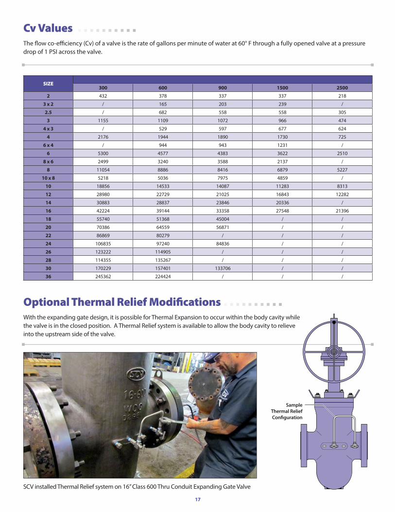
Cv ValuesThe flow co-efficiency (Cv) of a valve is the rate of gallons per minute of water at 60° F through a fully opened valve at a pressure drop of 1 PSI across the valve.
Optional Thermal Relief ModificationsWith the expanding gate design, it is possible for Thermal Expansion to occur within the body cavity while the valve is in the closed position. A Thermal Relief system is available to allow the body cavity to relieve into the upstream side of the valve.
SIZE300 600 900 1500 2500
2 432 378 337 337 218
3 x 2 / 165 203 239 /
2.5 / 682 558 558 305
3 1155 1109 1072 966 474
4 x 3 / 529 597 677 624
4 2176 1944 1890 1730 725
6 x 4 / 944 943 1231 /
6 5300 4577 4383 3622 2510
8 x 6 2499 3240 3588 2137 /
8 11054 8886 8416 6879 5227
10 x 8 5218 5036 7975 4859 /
10 18856 14533 14087 11283 8313
12 28980 22729 21025 16843 12282
14 30883 28837 23846 20336 /
16 42224 39144 33358 27548 21396
18 55740 51368 45004 / /
20 70386 64559 56871 / /
22 86869 80279 / / /
24 106835 97240 84836 / /
26 123222 114905 / / /
28 114355 135267 / / /
30 170229 157401 133706 / /
36 245362 224424 / / /
SampleThermal Relief Con�guration
SCV installed Thermal Relief system on 16” Class 600 Thru Conduit Expanding Gate Valve
18
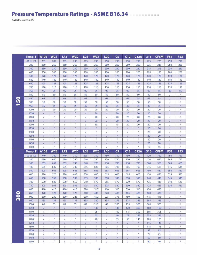
Pressure Temperature Ratings - ASME B16.34 note: Pressures in PSI
150
Temp. F a105 WCb lF2 WCC lCb WC6 lCC C5 C12 C12a 316 CF8M F51 F53-20 to 100 285 285 285 290 265 290 290 290 290 290 275 275 290 290
200 260 260 260 260 255 260 260 260 260 260 235 235 260 260300 230 230 230 230 230 230 230 230 230 230 215 215 230 230400 200 200 200 200 200 200 200 200 200 200 195 195 200 200500 170 170 170 170 170 170 170 170 170 170 170 170 170 170600 140 140 140 140 140 140 140 140 140 140 140 140 140 140650 125 125 125 125 125 125 125 125 125 125 125 125 125 125700 110 110 110 110 110 110 110 110 110 110 110 110 110 110750 95 95 95 95 95 95 95 95 95 95 95 95 95 95800 80 80 80 80 80 80 80 80 80 80 80 80 / /850 65 65 65 65 65 65 65 65 65 65 65 65 / /900 50 50 50 50 50 50 50 50 50 50 50 50 / /950 35 35 35 35 35 35 35 35 35 35 35 35 / /
1000 20 20 20 20 20 20 20 20 20 20 20 20 / /1050 / / / / / 20 / 20 20 20 20 20 / /1100 / / / / / 20 / 20 20 20 20 20 / /1150 / / / / / 20 / 20 20 20 20 20 / /1200 / / / / / 15 / 15 20 20 20 20 / /1250 / / / / / / / / / / 20 20 / /1300 / / / / / / / / / / 20 20 / /1350 / / / / / / / / / / 20 20 / /1400 / / / / / / / / / / 20 20 / /1450 / / / / / / / / / / 20 20 / /1500 / / / / / / / / / / 15 15 / /
300
Temp. F a105 WCb lF2 WCC lCb WC6 lCC C5 C12 C12a 316 CF8M F51 F53-20 to 100 740 740 740 750 695 750 750 750 750 750 720 720 750 750
200 680 680 680 750 660 750 750 750 750 750 620 620 745 745300 655 655 655 730 640 720 730 730 730 730 560 560 665 665400 635 635 635 705 615 695 705 705 705 705 515 515 615 615500 605 605 605 665 585 665 665 665 665 665 480 480 580 580600 570 570 570 605 550 605 605 605 605 605 450 450 555 555650 550 550 550 590 535 590 590 590 590 590 440 440 545 545700 530 530 530 555 510 570 555 570 570 570 435 435 540 540750 505 505 505 505 475 530 505 530 530 530 425 425 530 530800 410 410 410 410 390 510 410 510 510 510 420 420 / /850 320 320 320 320 300 485 320 485 485 485 420 420 / /900 230 230 230 225 200 450 225 375 450 450 415 415 / /950 135 135 135 135 135 320 135 275 375 385 385 385 / /
1000 85 85 85 85 85 215 85 200 255 365 365 365 / /1050 / / / / / 145 / 145 170 360 160 160 / /1100 / / / / / 95 / 100 115 300 305 305 / /1150 / / / / / 65 / 60 75 225 235 235 / /1200 / / / / / 40 / 35 50 145 185 185 / /1250 / / / / / / / / / / 145 145 / /1300 / / / / / / / / / / 115 115 / /1350 / / / / / / / / / / 95 95 / /1400 / / / / / / / / / / 75 75 / /1450 / / / / / / / / / / 60 60 / /1500 / / / / / / / / / / 40 40 / /
19
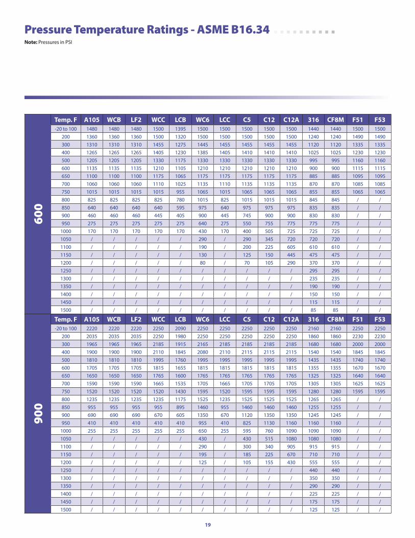
Pressure Temperature Ratings - ASME B16.34 note: Pressures in PSI
600
Temp. F a105 WCb lF2 WCC lCb WC6 lCC C5 C12 C12a 316 CF8M F51 F53-20 to 100 1480 1480 1480 1500 1395 1500 1500 1500 1500 1500 1440 1440 1500 1500
200 1360 1360 1360 1500 1320 1500 1500 1500 1500 1500 1240 1240 1490 1490300 1310 1310 1310 1455 1275 1445 1455 1455 1455 1455 1120 1120 1335 1335400 1265 1265 1265 1405 1230 1385 1405 1410 1410 1410 1025 1025 1230 1230500 1205 1205 1205 1330 1175 1330 1330 1330 1330 1330 995 995 1160 1160600 1135 1135 1135 1210 1105 1210 1210 1210 1210 1210 900 900 1115 1115650 1100 1100 1100 1175 1065 1175 1175 1175 1175 1175 885 885 1095 1095700 1060 1060 1060 1110 1025 1135 1110 1135 1135 1135 870 870 1085 1085750 1015 1015 1015 1015 955 1065 1015 1065 1065 1065 855 855 1065 1065800 825 825 825 825 780 1015 825 1015 1015 1015 845 845 / /850 640 640 640 640 595 975 640 975 975 975 835 835 / /900 460 460 460 445 405 900 445 745 900 900 830 830 / /950 275 275 275 275 275 640 275 550 755 775 775 775 / /
1000 170 170 170 170 170 430 170 400 505 725 725 725 / /1050 / / / / / 290 / 290 345 720 720 720 / /1100 / / / / / 190 / 200 225 605 610 610 / /1150 / / / / / 130 / 125 150 445 475 475 / /1200 / / / / / 80 / 70 105 290 370 370 / /1250 / / / / / / / / / / 295 295 / /1300 / / / / / / / / / / 235 235 / /1350 / / / / / / / / / / 190 190 / /1400 / / / / / / / / / / 150 150 / /1450 / / / / / / / / / / 115 115 / /1500 / / / / / / / / / / 85 85 / /
900
Temp. F a105 WCb lF2 WCC lCb WC6 lCC C5 C12 C12a 316 CF8M F51 F53-20 to 100 2220 2220 2220 2250 2090 2250 2250 2250 2250 2250 2160 2160 2250 2250
200 2035 2035 2035 2250 1980 2250 2250 2250 2250 2250 1860 1860 2230 2230300 1965 1965 1965 2185 1915 2165 2185 2185 2185 2185 1680 1680 2000 2000400 1900 1900 1900 2110 1845 2080 2110 2115 2115 2115 1540 1540 1845 1845500 1810 1810 1810 1995 1760 1995 1995 1995 1995 1995 1435 1435 1740 1740600 1705 1705 1705 1815 1655 1815 1815 1815 1815 1815 1355 1355 1670 1670650 1650 1650 1650 1765 1600 1765 1765 1765 1765 1765 1325 1325 1640 1640700 1590 1590 1590 1665 1535 1705 1665 1705 1705 1705 1305 1305 1625 1625750 1520 1520 1520 1520 1430 1595 1520 1595 1595 1595 1280 1280 1595 1595800 1235 1235 1235 1235 1175 1525 1235 1525 1525 1525 1265 1265 / /850 955 955 955 955 895 1460 955 1460 1460 1460 1255 1255 / /900 690 690 690 670 605 1350 670 1120 1350 1350 1245 1245 / /950 410 410 410 410 410 955 410 825 1130 1160 1160 1160 / /
1000 255 255 255 255 255 650 255 595 760 1090 1090 1090 / /1050 / / / / / 430 / 430 515 1080 1080 1080 / /1100 / / / / / 290 / 300 340 905 915 915 / /1150 / / / / / 195 / 185 225 670 710 710 / /1200 / / / / / 125 / 105 155 430 555 555 / /1250 / / / / / / / / / / 440 440 / /1300 / / / / / / / / / / 350 350 / /1350 / / / / / / / / / / 290 290 / /1400 / / / / / / / / / / 225 225 / /1450 / / / / / / / / / / 175 175 / /1500 / / / / / / / / / / 125 125 / /
20
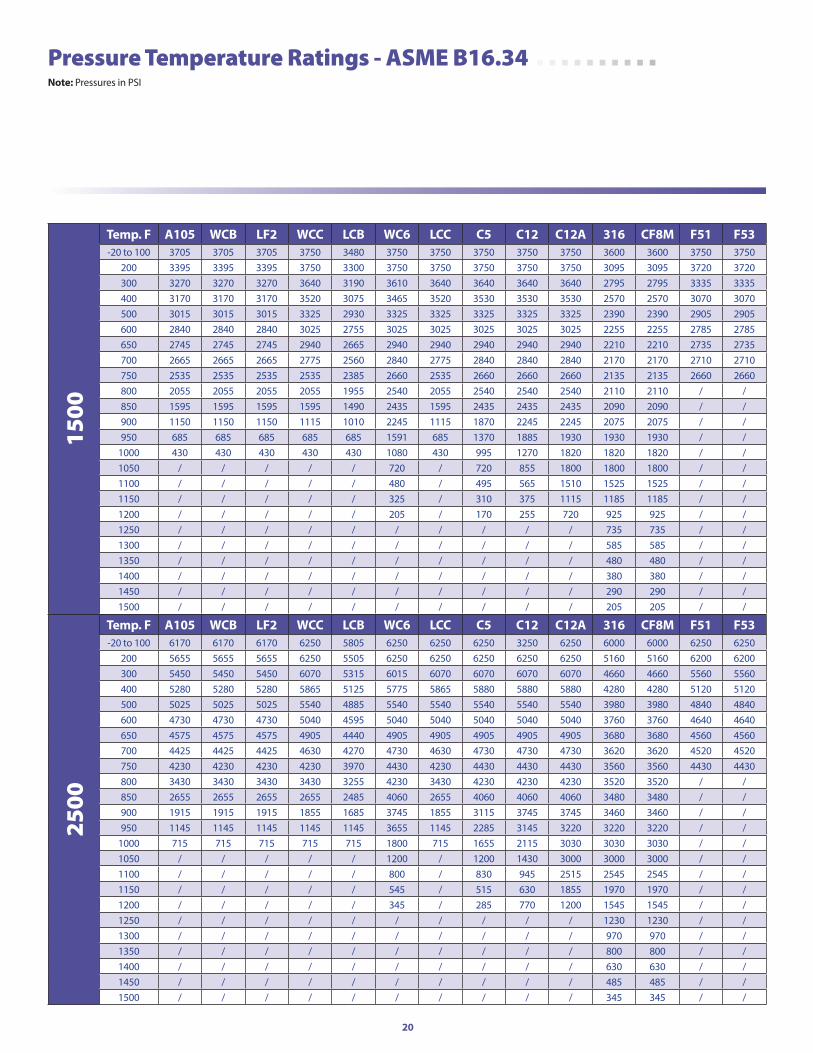
aSTM #
1500
Temp. F a105 WCb lF2 WCC lCb WC6 lCC C5 C12 C12a 316 CF8M F51 F53-20 to 100 3705 3705 3705 3750 3480 3750 3750 3750 3750 3750 3600 3600 3750 3750
200 3395 3395 3395 3750 3300 3750 3750 3750 3750 3750 3095 3095 3720 3720300 3270 3270 3270 3640 3190 3610 3640 3640 3640 3640 2795 2795 3335 3335400 3170 3170 3170 3520 3075 3465 3520 3530 3530 3530 2570 2570 3070 3070500 3015 3015 3015 3325 2930 3325 3325 3325 3325 3325 2390 2390 2905 2905600 2840 2840 2840 3025 2755 3025 3025 3025 3025 3025 2255 2255 2785 2785650 2745 2745 2745 2940 2665 2940 2940 2940 2940 2940 2210 2210 2735 2735700 2665 2665 2665 2775 2560 2840 2775 2840 2840 2840 2170 2170 2710 2710750 2535 2535 2535 2535 2385 2660 2535 2660 2660 2660 2135 2135 2660 2660800 2055 2055 2055 2055 1955 2540 2055 2540 2540 2540 2110 2110 / /850 1595 1595 1595 1595 1490 2435 1595 2435 2435 2435 2090 2090 / /900 1150 1150 1150 1115 1010 2245 1115 1870 2245 2245 2075 2075 / /950 685 685 685 685 685 1591 685 1370 1885 1930 1930 1930 / /
1000 430 430 430 430 430 1080 430 995 1270 1820 1820 1820 / /1050 / / / / / 720 / 720 855 1800 1800 1800 / /1100 / / / / / 480 / 495 565 1510 1525 1525 / /1150 / / / / / 325 / 310 375 1115 1185 1185 / /1200 / / / / / 205 / 170 255 720 925 925 / /1250 / / / / / / / / / / 735 735 / /1300 / / / / / / / / / / 585 585 / /1350 / / / / / / / / / / 480 480 / /1400 / / / / / / / / / / 380 380 / /1450 / / / / / / / / / / 290 290 / /1500 / / / / / / / / / / 205 205 / /
2500
Temp. F a105 WCb lF2 WCC lCb WC6 lCC C5 C12 C12a 316 CF8M F51 F53-20 to 100 6170 6170 6170 6250 5805 6250 6250 6250 3250 6250 6000 6000 6250 6250
200 5655 5655 5655 6250 5505 6250 6250 6250 6250 6250 5160 5160 6200 6200300 5450 5450 5450 6070 5315 6015 6070 6070 6070 6070 4660 4660 5560 5560400 5280 5280 5280 5865 5125 5775 5865 5880 5880 5880 4280 4280 5120 5120500 5025 5025 5025 5540 4885 5540 5540 5540 5540 5540 3980 3980 4840 4840600 4730 4730 4730 5040 4595 5040 5040 5040 5040 5040 3760 3760 4640 4640650 4575 4575 4575 4905 4440 4905 4905 4905 4905 4905 3680 3680 4560 4560700 4425 4425 4425 4630 4270 4730 4630 4730 4730 4730 3620 3620 4520 4520750 4230 4230 4230 4230 3970 4430 4230 4430 4430 4430 3560 3560 4430 4430800 3430 3430 3430 3430 3255 4230 3430 4230 4230 4230 3520 3520 / /850 2655 2655 2655 2655 2485 4060 2655 4060 4060 4060 3480 3480 / /900 1915 1915 1915 1855 1685 3745 1855 3115 3745 3745 3460 3460 / /950 1145 1145 1145 1145 1145 3655 1145 2285 3145 3220 3220 3220 / /
1000 715 715 715 715 715 1800 715 1655 2115 3030 3030 3030 / /1050 / / / / / 1200 / 1200 1430 3000 3000 3000 / /1100 / / / / / 800 / 830 945 2515 2545 2545 / /1150 / / / / / 545 / 515 630 1855 1970 1970 / /1200 / / / / / 345 / 285 770 1200 1545 1545 / /1250 / / / / / / / / / / 1230 1230 / /1300 / / / / / / / / / / 970 970 / /1350 / / / / / / / / / / 800 800 / /1400 / / / / / / / / / / 630 630 / /1450 / / / / / / / / / / 485 485 / /1500 / / / / / / / / / / 345 345 / /
Pressure Temperature Ratings - ASME B16.34 note: Pressures in PSI
21
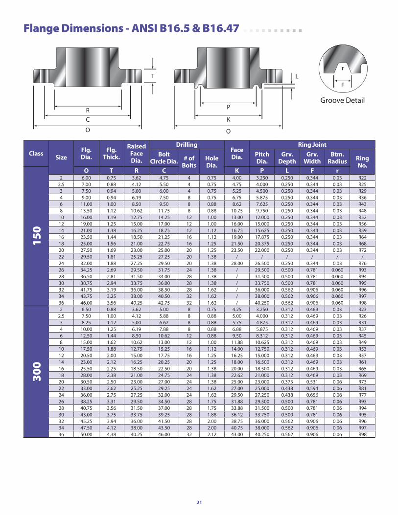
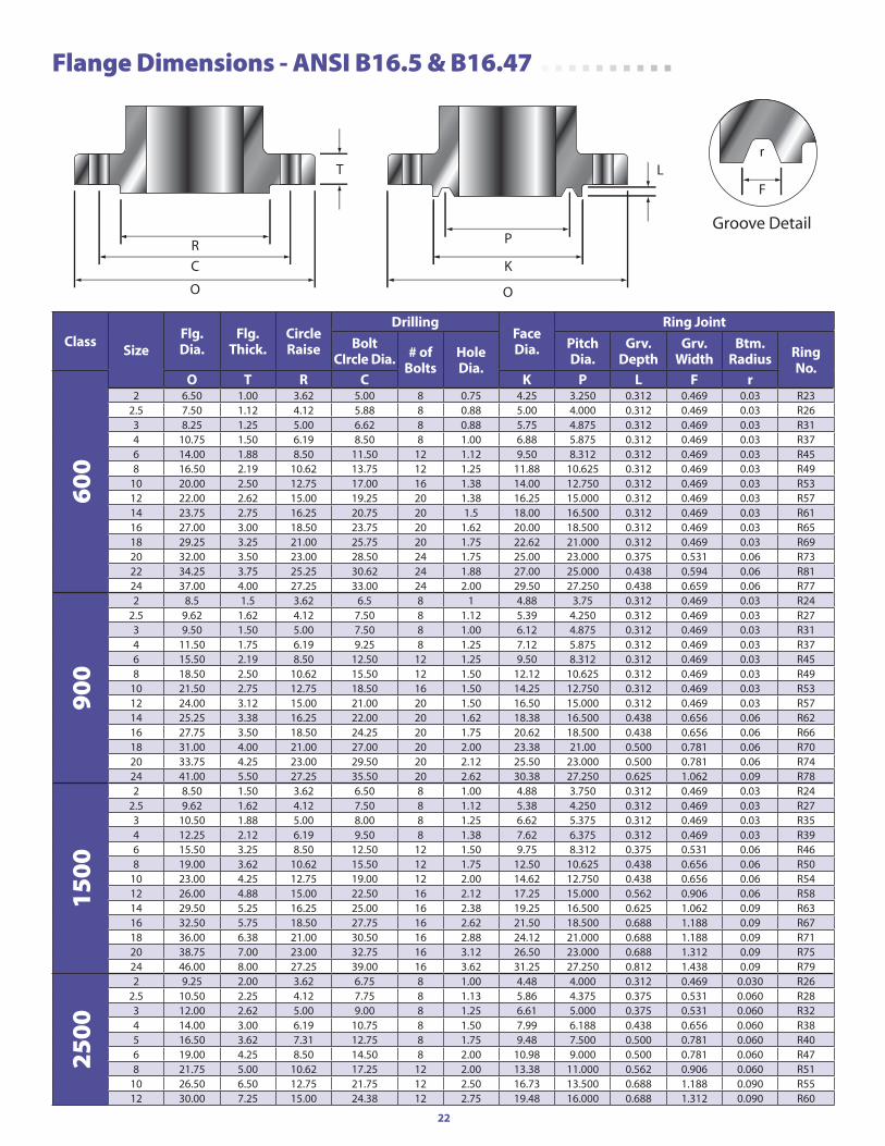
Flange Dimensions - ANSI B16.5 & B16.47
Class SizeFlg.dia.
Flg.Thick.
raised Facedia.
drillingFacedia.
ring Jointbolt
Circle dia. # ofbolts
holedia.
pitchdia.
grv.depth
grv.Width
btm.radius ring
no.
150
o T r C K p l F r2 6.00 0.75 3.62 4.75 4 0.75 4.00 3.250 0.250 0.344 0.03 R22
2.5 7.00 0.88 4.12 5.50 4 0.75 4.75 4.000 0.250 0.344 0.03 R253 7.50 0.94 5.00 6.00 4 0.75 5.25 4.500 0.250 0.344 0.03 R294 9.00 0.94 6.19 7.50 8 0.75 6.75 5.875 0.250 0.344 0.03 R366 11.00 1.00 8.50 9.50 8 0.88 8.62 7.625 0.250 0.344 0.03 R438 13.50 1.12 10.62 11.75 8 0.88 10.75 9.750 0.250 0.344 0.03 R48
10 16.00 1.19 12.75 14.25 12 1.00 13.00 12.000 0.250 0.344 0.03 R5212 19.00 1.25 15.00 17.00 12 1.00 16.00 15.000 0.250 0.344 0.03 R5614 21.00 1.38 16.25 18.75 12 1.12 16.75 15.625 0.250 0.344 0.03 R5916 23.50 1.44 18.50 21.25 16 1.12 19.00 17.875 0.250 0.344 0.03 R6418 25.00 1.56 21.00 22.75 16 1.25 21.50 20.375 0.250 0.344 0.03 R6820 27.50 1.69 23.00 25.00 20 1.25 23.50 22.000 0.250 0.344 0.03 R7222 29.50 1.81 25.25 27.25 20 1.38 / / / / / /24 32.00 1.88 27.25 29.50 20 1.38 28.00 26.500 0.250 0.344 0.03 R7626 34.25 2.69 29.50 31.75 24 1.38 / 29.500 0.500 0.781 0.060 R9328 36.50 2.81 31.50 34.00 28 1.38 / 31.500 0.500 0.781 0.060 R9430 38.75 2.94 33.75 36.00 28 1.38 / 33.750 0.500 0.781 0.060 R9532 41.75 3.19 36.00 38.50 28 1.62 / 36.000 0.562 0.906 0.060 R9634 43.75 3.25 38.00 40.50 32 1.62 / 38.000 0.562 0.906 0.060 R9736 46.00 3.56 40.25 42.75 32 1.62 / 40.250 0.562 0.906 0.060 R98
300
2 6.50 0.88 3.62 5.00 8 0.75 4.25 3.250 0.312 0.469 0.03 R232.5 7.50 1.00 4.12 5.88 8 0.88 5.00 4.000 0.312 0.469 0.03 R263 8.25 1.12 5.00 6.62 8 0.88 5.75 4.875 0.312 0.469 0.03 R314 10.00 1.25 6.19 7.88 8 0.88 6.88 5.875 0.312 0.469 0.03 R376 12.50 1.44 8.50 10.62 12 0.88 9.50 8.312 0.312 0.469 0.03 R458 15.00 1.62 10.62 13.00 12 1.00 11.88 10.625 0.312 0.469 0.03 R49
10 17.50 1.88 12.75 15.25 16 1.12 14.00 12.750 0.312 0.469 0.03 R5312 20.50 2.00 15.00 17.75 16 1.25 16.25 15.000 0.312 0.469 0.03 R5714 23.00 2.12 16.25 20.25 20 1.25 18.00 16.500 0.312 0.469 0.03 R6116 25.50 2.25 18.50 22.50 20 1.38 20.00 18.500 0.312 0.469 0.03 R6518 28.00 2.38 21.00 24.75 24 1.38 22.62 21.000 0.312 0.469 0.03 R6920 30.50 2.50 23.00 27.00 24 1.38 25.00 23.000 0.375 0.531 0.06 R7322 33.00 2.62 25.25 29.25 24 1.62 27.00 25.000 0.438 0.594 0.06 R8124 36.00 2.75 27.25 32.00 24 1.62 29.50 27.250 0.438 0.656 0.06 R7726 38.25 3.31 29.50 34.50 28 1.75 31.88 29.500 0.500 0.781 0.06 R9328 40.75 3.56 31.50 37.00 28 1.75 33.88 31.500 0.500 0.781 0.06 R9430 43.00 3.75 33.75 39.25 28 1.88 36.12 33.750 0.500 0.781 0.06 R9532 45.25 3.94 36.00 41.50 28 2.00 38.75 36.000 0.562 0.906 0.06 R9634 47.50 4.12 38.00 43.50 28 2.00 40.75 38.000 0.562 0.906 0.06 R9736 50.00 4.38 40.25 46.00 32 2.12 43.00 40.250 0.562 0.906 0.06 R98
Groove Detail
O
R
C K
P
O
LF
rT
22
Flange Dimensions - ANSI B16.5 & B16.47
Class SizeFlg.dia.
Flg.Thick.
Circleraise
drillingFacedia.
ring Jointbolt
Circle dia. # ofbolts
holedia.
pitchdia.
grv.depth
grv.Width
btm.radius ring
no.
600
o T r C K p l F r2 6.50 1.00 3.62 5.00 8 0.75 4.25 3.250 0.312 0.469 0.03 R23
2.5 7.50 1.12 4.12 5.88 8 0.88 5.00 4.000 0.312 0.469 0.03 R263 8.25 1.25 5.00 6.62 8 0.88 5.75 4.875 0.312 0.469 0.03 R314 10.75 1.50 6.19 8.50 8 1.00 6.88 5.875 0.312 0.469 0.03 R376 14.00 1.88 8.50 11.50 12 1.12 9.50 8.312 0.312 0.469 0.03 R458 16.50 2.19 10.62 13.75 12 1.25 11.88 10.625 0.312 0.469 0.03 R49
10 20.00 2.50 12.75 17.00 16 1.38 14.00 12.750 0.312 0.469 0.03 R5312 22.00 2.62 15.00 19.25 20 1.38 16.25 15.000 0.312 0.469 0.03 R5714 23.75 2.75 16.25 20.75 20 1.5 18.00 16.500 0.312 0.469 0.03 R6116 27.00 3.00 18.50 23.75 20 1.62 20.00 18.500 0.312 0.469 0.03 R6518 29.25 3.25 21.00 25.75 20 1.75 22.62 21.000 0.312 0.469 0.03 R6920 32.00 3.50 23.00 28.50 24 1.75 25.00 23.000 0.375 0.531 0.06 R7322 34.25 3.75 25.25 30.62 24 1.88 27.00 25.000 0.438 0.594 0.06 R8124 37.00 4.00 27.25 33.00 24 2.00 29.50 27.250 0.438 0.659 0.06 R77
900
2 8.5 1.5 3.62 6.5 8 1 4.88 3.75 0.312 0.469 0.03 R242.5 9.62 1.62 4.12 7.50 8 1.12 5.39 4.250 0.312 0.469 0.03 R273 9.50 1.50 5.00 7.50 8 1.00 6.12 4.875 0.312 0.469 0.03 R314 11.50 1.75 6.19 9.25 8 1.25 7.12 5.875 0.312 0.469 0.03 R376 15.50 2.19 8.50 12.50 12 1.25 9.50 8.312 0.312 0.469 0.03 R458 18.50 2.50 10.62 15.50 12 1.50 12.12 10.625 0.312 0.469 0.03 R49
10 21.50 2.75 12.75 18.50 16 1.50 14.25 12.750 0.312 0.469 0.03 R5312 24.00 3.12 15.00 21.00 20 1.50 16.50 15.000 0.312 0.469 0.03 R5714 25.25 3.38 16.25 22.00 20 1.62 18.38 16.500 0.438 0.656 0.06 R6216 27.75 3.50 18.50 24.25 20 1.75 20.62 18.500 0.438 0.656 0.06 R6618 31.00 4.00 21.00 27.00 20 2.00 23.38 21.00 0.500 0.781 0.06 R7020 33.75 4.25 23.00 29.50 20 2.12 25.50 23.000 0.500 0.781 0.06 R7424 41.00 5.50 27.25 35.50 20 2.62 30.38 27.250 0.625 1.062 0.09 R78
1500
2 8.50 1.50 3.62 6.50 8 1.00 4.88 3.750 0.312 0.469 0.03 R242.5 9.62 1.62 4.12 7.50 8 1.12 5.38 4.250 0.312 0.469 0.03 R273 10.50 1.88 5.00 8.00 8 1.25 6.62 5.375 0.312 0.469 0.03 R354 12.25 2.12 6.19 9.50 8 1.38 7.62 6.375 0.312 0.469 0.03 R396 15.50 3.25 8.50 12.50 12 1.50 9.75 8.312 0.375 0.531 0.06 R468 19.00 3.62 10.62 15.50 12 1.75 12.50 10.625 0.438 0.656 0.06 R50
10 23.00 4.25 12.75 19.00 12 2.00 14.62 12.750 0.438 0.656 0.06 R5412 26.00 4.88 15.00 22.50 16 2.12 17.25 15.000 0.562 0.906 0.06 R5814 29.50 5.25 16.25 25.00 16 2.38 19.25 16.500 0.625 1.062 0.09 R6316 32.50 5.75 18.50 27.75 16 2.62 21.50 18.500 0.688 1.188 0.09 R6718 36.00 6.38 21.00 30.50 16 2.88 24.12 21.000 0.688 1.188 0.09 R7120 38.75 7.00 23.00 32.75 16 3.12 26.50 23.000 0.688 1.312 0.09 R7524 46.00 8.00 27.25 39.00 16 3.62 31.25 27.250 0.812 1.438 0.09 R79
2500
2 9.25 2.00 3.62 6.75 8 1.00 4.48 4.000 0.312 0.469 0.030 R262.5 10.50 2.25 4.12 7.75 8 1.13 5.86 4.375 0.375 0.531 0.060 R283 12.00 2.62 5.00 9.00 8 1.25 6.61 5.000 0.375 0.531 0.060 R324 14.00 3.00 6.19 10.75 8 1.50 7.99 6.188 0.438 0.656 0.060 R385 16.50 3.62 7.31 12.75 8 1.75 9.48 7.500 0.500 0.781 0.060 R406 19.00 4.25 8.50 14.50 8 2.00 10.98 9.000 0.500 0.781 0.060 R478 21.75 5.00 10.62 17.25 12 2.00 13.38 11.000 0.562 0.906 0.060 R51
10 26.50 6.50 12.75 21.75 12 2.50 16.73 13.500 0.688 1.188 0.090 R5512 30.00 7.25 15.00 24.38 12 2.75 19.48 16.000 0.688 1.312 0.090 R60
Groove Detail
O
R
C K
P
O
LF
rT
23
Your 6D SolutionFrom pipelines to processing, SCV has the 6D products to complete your projects.
• oil & gas distribution, processing & Transmission
• Wastewater Collection & Treatment
• Crude handling & Treatment• petro Chemical & refineries• Waste Transfer & processing• Slurry Transfer & processing• Steam Systems• general industries
Southern California Valve is a respected domestic manufacturer and “go-to” source for standard commodity valves and hard-to-find specialty valves. SCV offers a complete line of gates, globes, checks, balls, plugs, and sub-sea designs in all sizes, pressure classes, and metallurgical compositions.
SCV valves are built to meet and exceed the most rigorous quality and production standards. SCV operates under the API Q1 Quality Management System and holds API 6A, API 6D, ISO: 9001:2008, CE-PED, and CRN certifications.
For more than 40 years, SCV has served industries including the power, paper and pulp, oil and gas, transmission, and petro-chemical sectors. We pride ourselves on our high quality products, timely delivery capabilities, and competitive prices.
Complete your jobs faster by taking advantage of our $45 million ready-to-ship standard & hard-to-find inventory.
www.scvvalve.com • 281.482.4728
Built USA Tough!
24
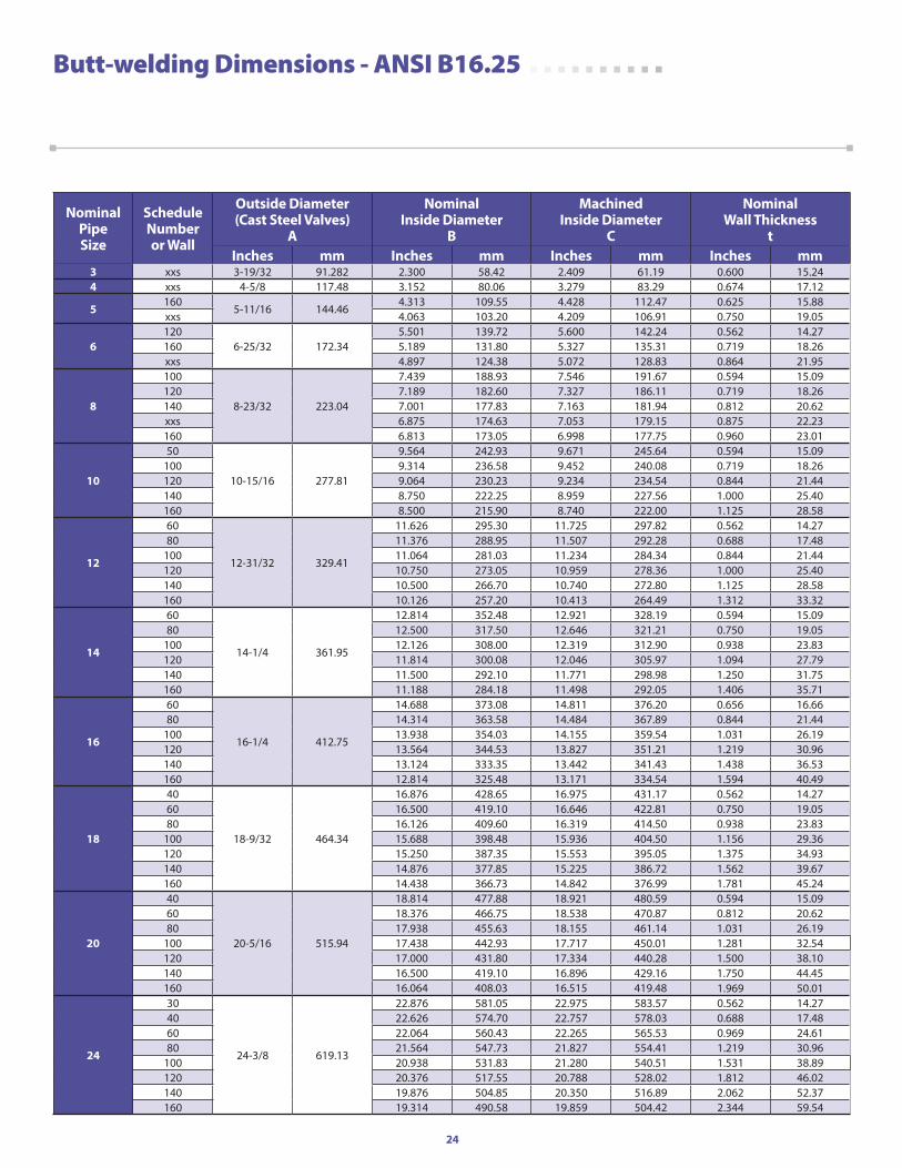
Butt-welding Dimensions - ANSI B16.25
nominalpipeSize
Schedulenumberor Wall
outside diameter(Cast Steel Valves)
a
nominalinside diameter
b
Machinedinside diameter
C
nominalWall Thickness
tinches mm inches mm inches mm inches mm
3 xxs 3-19/32 91.282 2.300 58.42 2.409 61.19 0.600 15.244 xxs 4-5/8 117.48 3.152 80.06 3.279 83.29 0.674 17.12
5160
5-11/16 144.464.313 109.55 4.428 112.47 0.625 15.88
xxs 4.063 103.20 4.209 106.91 0.750 19.05
6120
6-25/32 172.345.501 139.72 5.600 142.24 0.562 14.27
160 5.189 131.80 5.327 135.31 0.719 18.26xxs 4.897 124.38 5.072 128.83 0.864 21.95
8
100
8-23/32 223.04
7.439 188.93 7.546 191.67 0.594 15.09120 7.189 182.60 7.327 186.11 0.719 18.26140 7.001 177.83 7.163 181.94 0.812 20.62xxs 6.875 174.63 7.053 179.15 0.875 22.23160 6.813 173.05 6.998 177.75 0.960 23.01
10
50
10-15/16 277.81
9.564 242.93 9.671 245.64 0.594 15.09100 9.314 236.58 9.452 240.08 0.719 18.26120 9.064 230.23 9.234 234.54 0.844 21.44140 8.750 222.25 8.959 227.56 1.000 25.40160 8.500 215.90 8.740 222.00 1.125 28.58
12
60
12-31/32 329.41
11.626 295.30 11.725 297.82 0.562 14.2780 11.376 288.95 11.507 292.28 0.688 17.48
100 11.064 281.03 11.234 284.34 0.844 21.44120 10.750 273.05 10.959 278.36 1.000 25.40140 10.500 266.70 10.740 272.80 1.125 28.58160 10.126 257.20 10.413 264.49 1.312 33.32
14
60
14-1/4 361.95
12.814 352.48 12.921 328.19 0.594 15.0980 12.500 317.50 12.646 321.21 0.750 19.05
100 12.126 308.00 12.319 312.90 0.938 23.83120 11.814 300.08 12.046 305.97 1.094 27.79140 11.500 292.10 11.771 298.98 1.250 31.75160 11.188 284.18 11.498 292.05 1.406 35.71
16
60
16-1/4 412.75
14.688 373.08 14.811 376.20 0.656 16.6680 14.314 363.58 14.484 367.89 0.844 21.44
100 13.938 354.03 14.155 359.54 1.031 26.19120 13.564 344.53 13.827 351.21 1.219 30.96140 13.124 333.35 13.442 341.43 1.438 36.53160 12.814 325.48 13.171 334.54 1.594 40.49
18
40
18-9/32 464.34
16.876 428.65 16.975 431.17 0.562 14.2760 16.500 419.10 16.646 422.81 0.750 19.0580 16.126 409.60 16.319 414.50 0.938 23.83
100 15.688 398.48 15.936 404.50 1.156 29.36120 15.250 387.35 15.553 395.05 1.375 34.93140 14.876 377.85 15.225 386.72 1.562 39.67160 14.438 366.73 14.842 376.99 1.781 45.24
20
40
20-5/16 515.94
18.814 477.88 18.921 480.59 0.594 15.0960 18.376 466.75 18.538 470.87 0.812 20.6280 17.938 455.63 18.155 461.14 1.031 26.19
100 17.438 442.93 17.717 450.01 1.281 32.54120 17.000 431.80 17.334 440.28 1.500 38.10140 16.500 419.10 16.896 429.16 1.750 44.45160 16.064 408.03 16.515 419.48 1.969 50.01
24
30
24-3/8 619.13
22.876 581.05 22.975 583.57 0.562 14.2740 22.626 574.70 22.757 578.03 0.688 17.4860 22.064 560.43 22.265 565.53 0.969 24.6180 21.564 547.73 21.827 554.41 1.219 30.96
100 20.938 531.83 21.280 540.51 1.531 38.89120 20.376 517.55 20.788 528.02 1.812 46.02140 19.876 504.85 20.350 516.89 2.062 52.37160 19.314 490.58 19.859 504.42 2.344 59.54
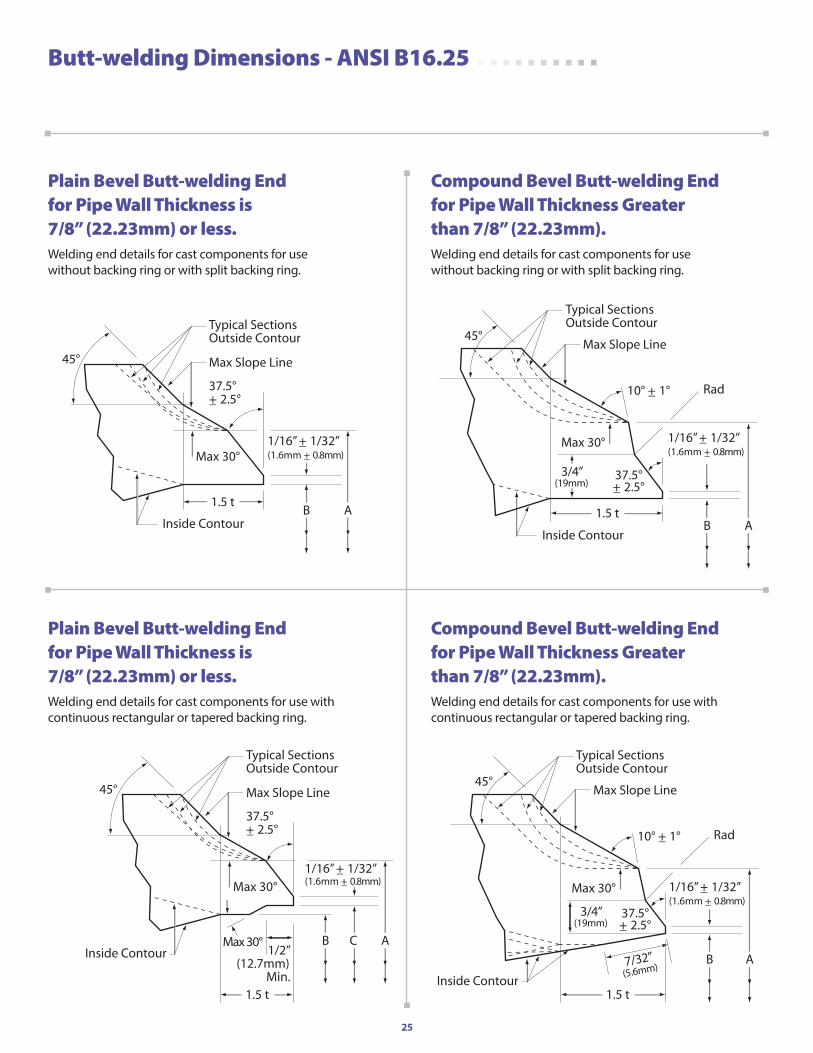
25
37.5°+_ 2.5°
1/16” +_ 1/32”(1.6mm +_ 0.8mm)
1.5 tB A
45°
Max 30°
Max Slope Line
Inside Contour
Typical SectionsOutside Contour
Butt-welding Dimensions - ANSI B16.25
Max Slope Line
Inside Contour
Typical SectionsOutside Contour
1.5 t
1/16” +_ 1/32”(1.6mm +_ 0.8mm)
3/4”(19mm)
B A
Max 30°
45°
10° +_ 1° Rad
37.5°+_ 2.5°
37.5°+_ 2.5°
1/16” +_ 1/32”(1.6mm +_ 0.8mm)
1.5 t
B A
45°
Max 30°
Max 30°1/2”
(12.7mm)Min.
Max Slope Line
Inside Contour
Typical SectionsOutside Contour
C
Max Slope Line
Inside Contour
Typical SectionsOutside Contour
1.5 t
1/16” +_ 1/32”(1.6mm +_ 0.8mm)
3/4”(19mm)
7/32”(5.6mm)
B A
Max 30°
45°
10° +_ 1° Rad
37.5°+_ 2.5°
Plain Bevel Butt-welding End for Pipe Wall Thickness is 7/8” (22.23mm) or less.Welding end details for cast components for use without backing ring or with split backing ring.
Compound Bevel Butt-welding End for Pipe Wall Thickness Greater than 7/8” (22.23mm).Welding end details for cast components for use without backing ring or with split backing ring.
Plain Bevel Butt-welding End for Pipe Wall Thickness is 7/8” (22.23mm) or less.Welding end details for cast components for use with continuous rectangular or tapered backing ring.
Compound Bevel Butt-welding End for Pipe Wall Thickness Greater than 7/8” (22.23mm).Welding end details for cast components for use with continuous rectangular or tapered backing ring.
26
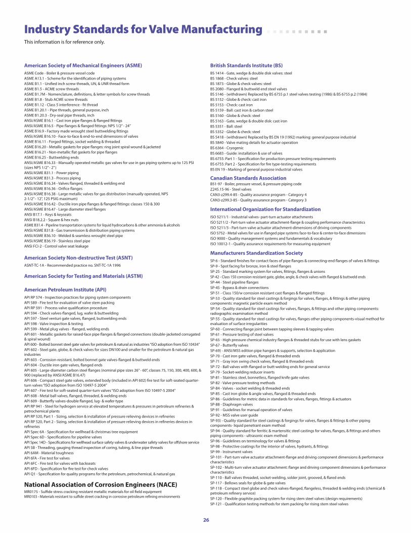
Industry Standards for Valve Manufacturing
This information is for reference only.
american Society of Mechanical Engineers (aSME)ASME Code - Boiler & pressure vessel codeASME A13.1 - Scheme for the identification of piping systemsASME B1.1 - Unified inch screw threads, UN, & UNR thread formASME B1.5 - ACME screw threadsASME B1.7M - Nomenclature, definitions, & letter symbols for screw threadsASME B1.8 - Stub ACME screw threadsASME B1.12 - Class 5 interference - fit threadASME B1.20.1 - Pipe threads, general purpose, inchASME B1.20.3 - Dry-seal pipe threads, inchANSI/ASME B16.1 - Cast iron pipe flanges & flanged fittingsANSI/ASME B16.5 - Pipe flanges & flanged fittings: NPS 1/2” - 24”ASME B16.9 - Factory made wrought steel buttwelding fittingsANSI/ASME B16.10 - Face-to-face & end-to-end dimensions of valvesASME B16.11 - Forged fittings, socket welding & threadedASME B16.20 - Metallic gaskets for pipe flanges: ring joint spiral wound & jacketedASME B16.21 - Non-metallic flat gaskets for pipe flangesASME B16.25 - Buttwelding endsANSI/ASME B16.33 - Manually operated metallic gas valves for use in gas piping systems up to 125 PSI (sizes NPS 1/2” - 2” )ANSI/ASME B31.1 - Power pipingANSI/ASME B31.3 - Process pipingANSI/ASME B16.34 - Valves flanged, threaded & welding endANSI/ASME B16.36 - Orifice flangesANSI/ASME B16.38 - Large metallic valves for gas distribution (manually operated, NPS 2-1/2” - 12”, 125 PSIG maximum)ANSI/ASME B16.42 - Ductile iron pipe flanges & flanged fittings: classes 150 & 300ANSI/ASME B16.47 - Large diameter steel flangesANSI B17.1 - Keys & keyseatsANSI B18.2.2 - Square & hex nutsASME B31.4 - Pipeline transportation systems for liquid hydrocarbons & other ammonia & alcoholsANSI/ASME B31.8 - Gas transmission & distribution piping systemsANSI/ASME B36.10 - Welded & seamless wrought steel pipeANSI/ASME B36.19 - Stainless steel pipeANSI FCI-2 - Control valve seat leakage
american Society non-destructive Test (aSnT)ASNT-TC-1A - Recommended practice no. SNT-TC-1A 1996
american Society for Testing and Materials (aSTM)
american petroleum institute (api)API RP 574 - Inspection practices for piping system componentsAPI 589 - Fire test for evaluation of valve stem packingAPI RP 591 - Process valve qualification procedureAPI 594 - Check valves-flanged, lug, wafer & buttweldingAPI 597 - Steel venturi gate valves, flanged, buttwelding endsAPI 598 - Valve inspection & testingAPI 599 - Metal plug valves - flanged, welding endsAPI 601 - Metallic gaskets for raised-face pipe flanges & flanged connections (double-jacketed corrugated & spiral wound)API 600 - Bolted bonnet steel gate valves for petroleum & natural as industries “ISO adoption from ISO 10434”API 602 - Steel gate, globe, & check valves for sizes DN100 and smaller for the petroleum & natural gas industriesAPI 603 - Corrosion-resistant, bolted bonnet gate valves-flanged & buttweld ends API 604 - Ductile iron gate valves, flanged endsAPI 605 - Large-diameter carbon steel flanges (nominal pipe sizes 26” - 60”, classes 75, 150, 300, 400, 600, & 900 (replaced by ANSI/ASME B16.47)API 606 - Compact steel gate valves, extended body (included in API 602) fire test for soft-seated quarter-turn valves “ISO adoption from ISO 10497-5 2004”API 607 - Fire test for soft-seated quarter-turn valves “ISO adoption from ISO 10497-5 2004” API 608 - Metal ball valves, flanged, threaded, & welding endsAPI 609 - Butterfly valves-double flanged, lug- & wafer-typeAPI RP 941 - Steel for hydrogen service at elevated temperatures & pressures in petroleum refineries & petrochemical plantsAPI RP 520, Part 1 - Sizing, selection & installation of pressure relieving devices in refineriesAPI RP 520, Part 2 - Sizing, selection & installation of pressure relieving devices in refineries devices in refineriesAPI Spec 6A - Specification for wellhead & christmas tree equipmentAPI Spec 6D - Specifications for pipeline valvesAPI Spec 14D - Specifications for wellhead surface safety valves & underwater safety valves for offshore serviceAPI 5B - Threading, gauging thread inspection of coring, tubing, & line pipe threadsAPI 6AM - Material toughnessAPI 6FA - Fire test for valvesAPI 6FC - Fire test for valves with backseatsAPI 6FD - Specification for fire test for check valvesAPI Q1 - Specification for quality programs for the petroleum, petrochemical, & natural gas
national association of Corrosion Engineers (naCE) MR0175 - Sulfide stress cracking resistant metallic materials for oil field equipment MR0103 - Materials resistant to sulfide street cracking in corrosive petroleum refining environments
british Standards institute (bS)BS 1414 - Gate, wedge & double disk valves: steelBS 1868 - Check valves: steelBS 1873 - Globe & check valves: steelBS 2080 - Flanged & buttweld end steel valvesBS 5146 - (withdrawn) Replaced by BS 6755 p.1 steel valves testing (1986) & BS 6755 p.2 (1984) BS 5152 - Globe & check: cast ironBS 5153 - Check: cast ironBS 5159 - Ball: cast iron & carbon steelBS 5160 - Globe & check: steelBS 5163 - Gate, wedge & double disk: cast ironBS 5351 - Ball: steelBS 5352 - Globe & check: steelBS 5418 - (withdrawn) Replaced by BS EN 19 (1992) marking: general purpose industrialBS 5840 - Valve mating details for actuator operationBS 6364 - CryogenicBS 6683 - Guide: installation & use of valvesBS 6755: Part 1 - Specification for production pressure testing requirementsBS 6755: Part 2 - Specification for fire type-testing requirementsBS EN 19 - Marking of general purpose industrial valves
Canadian Standards associationB51-97 - Boiler, pressure vessel, & pressure piping code Z245.15-96 - Steel valves CAN3-z299.4-85 - Quality assurance program - Category 4 CAN3-z299.3-85 - Quality assurance program - Category 3
international organization for StandardizationISO 5211/1 - Industrial valves- part-turn actuator attachmentsISO 5211/2 - Part-turn valve actuator attachment-flange & coupling performance characteristicsISO 5211/3 - Part-turn valve actuator attachment-dimensions of driving componentsISO 5752 - Metal valves for use in flanged pipe systems face-to-face & center-to-face dimensionsISO 9000 - Quality management systems and fundamentals & vocabularyISO 10012-1 - Quality assurance requirements for measuring equipment
Manufacturers Standardization SocietySP-6 - Standard finishes for contact faces of pipe flanges & connecting-end flanges of valves & fittingsSP-9 - Spot facing for bronze, iron & steel flangesSP-25 - Standard marking system for valves, fittings, flanges & unionsSP-42 - Class 150 corrosion resistant gate, globe, angle, & check valves with flanged & buttweld endsSP-44 - Steel pipeline flangesSP-45 - Bypass & drain connectionsSP-51 - Class 150/w corrosion resistant cast flanges & flanged fittingsSP-53 - Quality standard for steel castings & forgings for valves, flanges, & fittings & other piping components: magnetic particle exam methodSP-54 - Quality standard for steel castings for valves, flanges, & fittings and other piping components: radiographic examination methodSP-55 - Quality standard for steel castings for valves, flanges other piping components-visual method for evaluation of surface irregularitiesSP-60 - Connecting flange joint between tapping sleeves & tapping valvesSP-61 - Pressure testing of steel valvesSP-65 - High pressure chemical industry flanges & threaded stubs for use with lens gasketsSP-67 - Butterfly valvesSP-69) - ANSI/MSS edition pipe hangers & supports, selection & applicationSP-70 - Cast iron gate valves, flanged & threaded endsSP-71 - Gray iron swing check valves, flanged & threaded endsSP-72 - Ball valves with flanged or butt-welding ends for general serviceSP-79 - Socket-welding reducer insertsSP-81 - Stainless steel, bonnetless, flanged knife gate valvesSP-82 - Valve pressure testing methodsSP-84 - Valves - socket welding & threaded endsSP-85 - Cast iron globe & angle valves, flanged & threaded endsSP-86 - Guidelines for metric data in standards for valves, flanges, fittings & actuatorsSP-88 - Diaphragm valvesSP-91 - Guidelines for manual operation of valvesSP-92 - MSS valve user guideSP-93) - Quality standard for steel castings & forgings for valves, flanges & fittings & other piping components- liquid penetrant exam methodSP-94 - Quality standard for ferritic & martensitic steel castings for valves, flanges, & fittings and others piping components - ultrasonic exam methodSP-96 - Guidelines on terminology for valves & fittingsSP-98 - Protective coatings for the interior of valves, hydrants, & fittingsSP-99 - Instrument valvesSP-101 - Part-turn valve actuator attachment-flange and driving component dimensions & performance characteristicsSP-102 - Multi-turn valve actuator attachment: flange and driving component dimensions & performance characteristicsSP-110 - Ball valves threaded, socket-welding, solder joint, grooved, & flared endsSP-117 - Bellows seals for globe & gate valvesSP-118 - Compact steel globe and check valves-flanged, flangeless, threaded & welding ends (chemical & petroleum refinery service)SP-120 - Flexible graphite packing system for rising stem steel valves (design requirements)SP-121 - Qualification testing methods for stem packing for rising stem steel valves
27
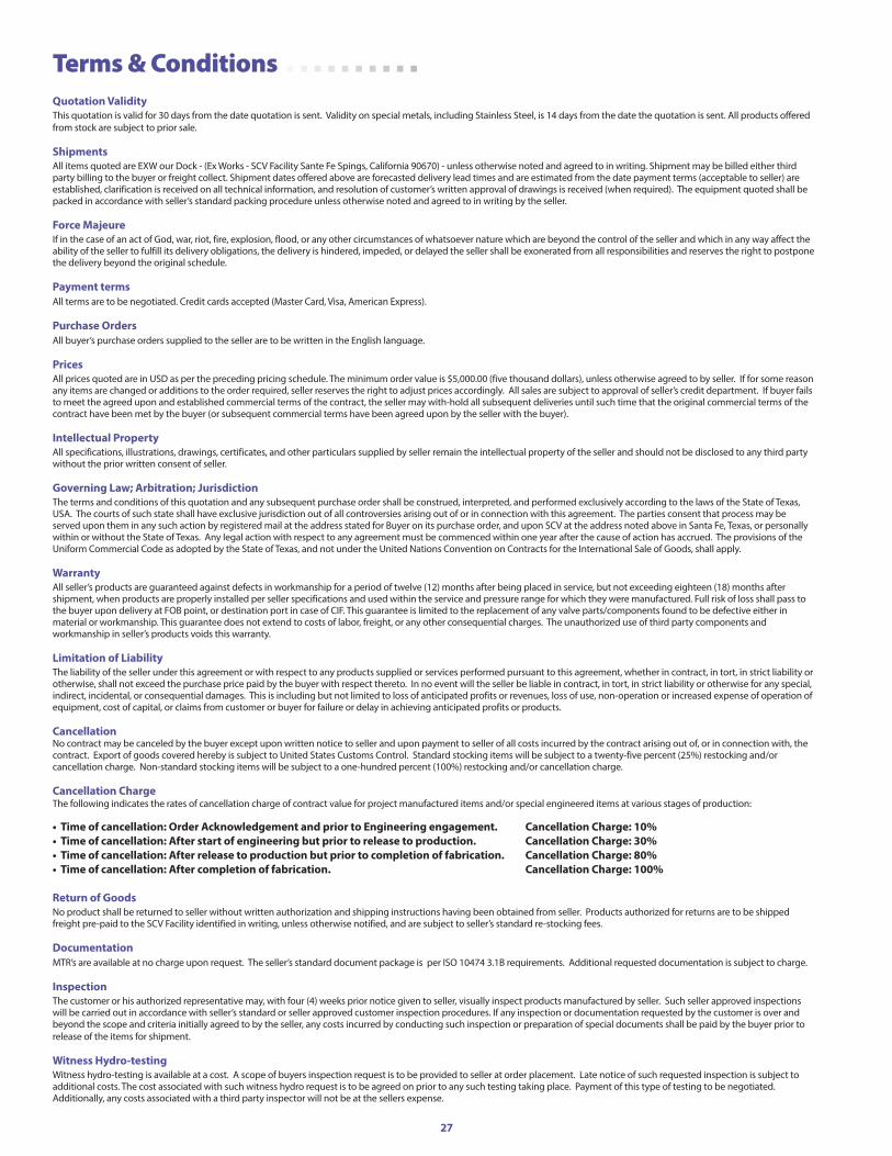
Terms & Conditions Quotation ValidityThis quotation is valid for 30 days from the date quotation is sent. Validity on special metals, including Stainless Steel, is 14 days from the date the quotation is sent. All products offered from stock are subject to prior sale.
ShipmentsAll items quoted are EXW our Dock - (Ex Works - SCV Facility Sante Fe Spings, California 90670) - unless otherwise noted and agreed to in writing. Shipment may be billed either third party billing to the buyer or freight collect. Shipment dates offered above are forecasted delivery lead times and are estimated from the date payment terms (acceptable to seller) are established, clarification is received on all technical information, and resolution of customer’s written approval of drawings is received (when required). The equipment quoted shall be packed in accordance with seller’s standard packing procedure unless otherwise noted and agreed to in writing by the seller.
Force MajeureIf in the case of an act of God, war, riot, fire, explosion, flood, or any other circumstances of whatsoever nature which are beyond the control of the seller and which in any way affect the ability of the seller to fulfill its delivery obligations, the delivery is hindered, impeded, or delayed the seller shall be exonerated from all responsibilities and reserves the right to postpone the delivery beyond the original schedule.
payment termsAll terms are to be negotiated. Credit cards accepted (Master Card, Visa, American Express).
purchase ordersAll buyer’s purchase orders supplied to the seller are to be written in the English language.
pricesAll prices quoted are in USD as per the preceding pricing schedule. The minimum order value is $5,000.00 (five thousand dollars), unless otherwise agreed to by seller. If for some reason any items are changed or additions to the order required, seller reserves the right to adjust prices accordingly. All sales are subject to approval of seller’s credit department. If buyer fails to meet the agreed upon and established commercial terms of the contract, the seller may with-hold all subsequent deliveries until such time that the original commercial terms of the contract have been met by the buyer (or subsequent commercial terms have been agreed upon by the seller with the buyer).
intellectual propertyAll specifications, illustrations, drawings, certificates, and other particulars supplied by seller remain the intellectual property of the seller and should not be disclosed to any third party without the prior written consent of seller.
governing law; arbitration; JurisdictionThe terms and conditions of this quotation and any subsequent purchase order shall be construed, interpreted, and performed exclusively according to the laws of the State of Texas, USA. The courts of such state shall have exclusive jurisdiction out of all controversies arising out of or in connection with this agreement. The parties consent that process may be served upon them in any such action by registered mail at the address stated for Buyer on its purchase order, and upon SCV at the address noted above in Santa Fe, Texas, or personally within or without the State of Texas. Any legal action with respect to any agreement must be commenced within one year after the cause of action has accrued. The provisions of the Uniform Commercial Code as adopted by the State of Texas, and not under the United Nations Convention on Contracts for the International Sale of Goods, shall apply.
WarrantyAll seller’s products are guaranteed against defects in workmanship for a period of twelve (12) months after being placed in service, but not exceeding eighteen (18) months after shipment, when products are properly installed per seller specifications and used within the service and pressure range for which they were manufactured. Full risk of loss shall pass to the buyer upon delivery at FOB point, or destination port in case of CIF. This guarantee is limited to the replacement of any valve parts/components found to be defective either in material or workmanship. This guarantee does not extend to costs of labor, freight, or any other consequential charges. The unauthorized use of third party components and workmanship in seller’s products voids this warranty.
limitation of liabilityThe liability of the seller under this agreement or with respect to any products supplied or services performed pursuant to this agreement, whether in contract, in tort, in strict liability or otherwise, shall not exceed the purchase price paid by the buyer with respect thereto. In no event will the seller be liable in contract, in tort, in strict liability or otherwise for any special, indirect, incidental, or consequential damages. This is including but not limited to loss of anticipated profits or revenues, loss of use, non-operation or increased expense of operation of equipment, cost of capital, or claims from customer or buyer for failure or delay in achieving anticipated profits or products.
CancellationNo contract may be canceled by the buyer except upon written notice to seller and upon payment to seller of all costs incurred by the contract arising out of, or in connection with, the contract. Export of goods covered hereby is subject to United States Customs Control. Standard stocking items will be subject to a twenty-five percent (25%) restocking and/or cancellation charge. Non-standard stocking items will be subject to a one-hundred percent (100%) restocking and/or cancellation charge.
Cancellation ChargeThe following indicates the rates of cancellation charge of contract value for project manufactured items and/or special engineered items at various stages of production:
• Time of cancellation: Order Acknowledgement and prior to Engineering engagement. Cancellation Charge: 10%• Time of cancellation: After start of engineering but prior to release to production. Cancellation Charge: 30%• Time of cancellation: After release to production but prior to completion of fabrication. Cancellation Charge: 80%• Time of cancellation: After completion of fabrication. Cancellation Charge: 100% return of goodsNo product shall be returned to seller without written authorization and shipping instructions having been obtained from seller. Products authorized for returns are to be shipped freight pre-paid to the SCV Facility identified in writing, unless otherwise notified, and are subject to seller’s standard re-stocking fees.
documentationMTR’s are available at no charge upon request. The seller’s standard document package is per ISO 10474 3.1B requirements. Additional requested documentation is subject to charge.
inspectionThe customer or his authorized representative may, with four (4) weeks prior notice given to seller, visually inspect products manufactured by seller. Such seller approved inspections will be carried out in accordance with seller’s standard or seller approved customer inspection procedures. If any inspection or documentation requested by the customer is over and beyond the scope and criteria initially agreed to by the seller, any costs incurred by conducting such inspection or preparation of special documents shall be paid by the buyer prior to release of the items for shipment.
Witness hydro-testingWitness hydro-testing is available at a cost. A scope of buyers inspection request is to be provided to seller at order placement. Late notice of such requested inspection is subject to additional costs. The cost associated with such witness hydro request is to be agreed on prior to any such testing taking place. Payment of this type of testing to be negotiated. Additionally, any costs associated with a third party inspector will not be at the sellers expense.
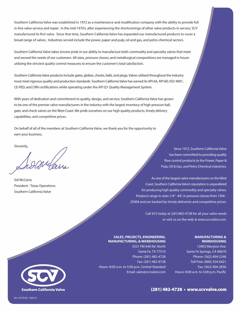
Southern California Valve was established in 1972 as a maintenance and modification company with the ability to provide full
in-line valve service and repair. In the mid-1970’s, after experiencing the shortcomings of other valve products in service, SCV
manufactured its first valve. Since that time, Southern California Valve has expanded our manufactured products to cover a
broad range of valves. Industries served include the power, paper and pulp, oil and gas, and petro-chemical sectors.
Southern California Valve takes sincere pride in our ability to manufacture both commodity and specialty valves that meet
and exceed the needs of our customers. All sizes, pressure classes, and metallurgical compositions are managed in house
utilizing the strictest quality control measures to ensure the customer’s total satisfaction.
Southern California Valve products include gates, globes, checks, balls, and plugs. Valves utilized throughout the industry
must meet rigorous quality and production standards. Southern California Valve has earned its API 6A, API 6D, ISO: 9001,
CE-PED, and CRN certifications while operating under the API Q1 Quality Management System.
With years of dedication and commitment to quality, design, and service, Southern California Valve has grown
to be one of the premier valve manufacturers in the industry with the largest inventory of high pressure ball,
gate, and check valves on the West Coast. We pride ourselves on our high quality products, timely delivery
capabilities, and competitive prices.
On behalf of all of the members at Southern California Valve, we thank you for the opportunity to
earn your business.
Sincerely,
Sid McCarra
President - Texas Operations
Southern California Valve
Since 1972, Southern California Valve
has been committed to providing quality
flow control products to the Power, Paper &
Pulp, Oil & Gas, and Petro Chemical industries.
As one of the largest valve manufacturers on the West
Coast, Southern California Valve’s reputation is unparalleled
for producing high quality commodity and specialty valves.
Products range in sizes 1/4” - 84”, in pressure classes from 150# -
2500# and are backed by timely deliveries and competitive prices.
Call SCV today at (281)482-4728 for all your valve needs
or visit us on the web @ www.scvvalve.com.
ManuFaCTuring & WarEhouSing
13903 Maryton Ave.Santa Fe Springs, CA 90670
Phone: (562) 404-2246Toll Free: (800) 554-6421
Fax: (562) 404-2836Hours: 8:00 a.m. to 5:00 p.m. Pacific
SalES, proJECTS, EnginEEring, ManuFaCTuring, & WarEhouSing
3521 FM 646 Rd. NorthSanta Fe, TX 77510
Phone: (281) 482-4728Fax: (281) 482-9728
Hours: 8:00 a.m. to 5:00 p.m. Central StandardEmail: [email protected]
(281) 482-4728 • www.scvvalve.com
Rev: SCVTCGV - 032213